chapter6 report on comments/2009 uniform plumbing code...operating pressure in thehot or cold...
TRANSCRIPT
601.0 Running Hot and Cold Water Required.601.1 Except where not deemed necessary for safetyor sanitation by the Authority Having Jurisdiction,each plumbing fixture shall be provided with anadequate supply of potable running water pipedthereto in an approved manner, so arranged as toflush and keep it in a clean and sanitary conditionwithout danger of backflow or cross-connection.
In occupancies where plumbing fixtures areinstalled for private use, hot water shall be requiredfor bathing, washing, laundry, cooking purposes,dishwashing or maintenance. In occupancies whereplumbing fixtures are installed for public use, hotwater shall be required for bathing and washingpurposes. This requirement shall not supersede therequirements for individual temperature controllimitations for public lavatories, bathtubs, whirlpoolbathtubs and shower control valves.
Water closets and urinals shall be flushed bymeans of an approved flush tank or flushometervalve. In jurisdictions that adopt Chapter 16, waterclosets, urinals, and trap primers in designated non-residential buildings shall be permitted to beprovided with reclaimed water as defined andregulated by Chapter 16 of this code.
Exception: Listed fixtures that do not requirewater for their operation and are not connectedto the water supply.
601.2 Identification of a Potable and NonpotableWater System. In buildings where potable waterand nonpotable water systems are installed, eachsystem shall be clearly identified. Each system shallbe color coded as follows:
601.2.1 Potable Water – Green background withwhite lettering.601.2.2 Nonpotable Water – Yellow backgroundwith black lettering, with the words “Caution:Nonpotable water, do not drink.”
Each system shall be identified with acolored band to designate the liquid beingconveyed, and the direction of normal flow shallbe clearly shown. The minimum size of theletters and length of the color field shall conformto Table 6-1.
A colored identification band shall beindicated every twenty (20) feet (6,096 mm), notless than once per room, and shall be visiblefrom the floor level.
Where vacuum breakers or backflowpreventers are installed with fixtures listed inTable 14-1, identification of the discharge side
shall be permitted to be omitted. Each outlet onthe nonpotable water line that could be used forspecial purposes shall be posted as follows:“Caution: Nonpotable water, do not drink.”601.2.3 Reclaimed Water – Purple (Pantonecolor No. 512) background and shall beimprinted in nominal one-half (1/2) inch (12.7mm) high, black upper-case letters, with thewords “Caution: Reclaimed water, do notdrink.”
601.3 Faucets and diverters shall be connected to thewater distribution system so that hot watercorresponds to the left side of the fittings.
TABLE 6-1Minimum Length of Color Field and Size of Letters
Outside Diameter Minimum Length Minimum Sizeof Pipe or Covering of Color Field of Lettersinches (mm) inches (mm) inches (mm)1/2 to1-1/4 (15 to 32) 8 (203) 1/2 (12.7)
1-1/2 to 2 (40 to 50) 8 (203) 3/4 (19.1)
2-1/2 to 6 (65 to 150) 12 (305) 1-1/4 (32)
8 to 10 (200 to 250) 24 (619) 2-1/2 (64)
Over 10 (Over 250) 32 (813) 3-1/2 (89)
602.0 Unlawful Connections602.1 No installation of potable water supply pipingor part thereof shall be made in such a manner that itwill be possible for used, unclean, polluted, orcontaminated water, mixtures, or substances to enterany portion of such piping from any tank, receptor,equipment, or plumbing fixture by reason of back-siphonage, suction, or any other cause, either duringnormal use and operation thereof, or when any suchtank, receptor, equipment, or plumbing fixture isflooded or subject to pressure exceeding theoperating pressure in the hot or cold water piping.602.2 No person shall make a connection or allowone (1) to exist between pipes or conduits carryingdomestic water supplied by any public or privatewater service system, and any pipes, conduits, orfixtures containing or carrying water from anyother source or containing or carrying water thathas been used for any purpose whatsoever, or anypiping carrying chemicals, liquids, gases, or anysubstances whatsoever, unless there is provided abackflow prevention device approved for thepotential hazard and maintained in accordance
99
CHAPTER 6WATER SUPPLY AND DISTRIBUTION
PRE-PRIN
T
UNIFORM PLUMBING CODETable 6-2
100
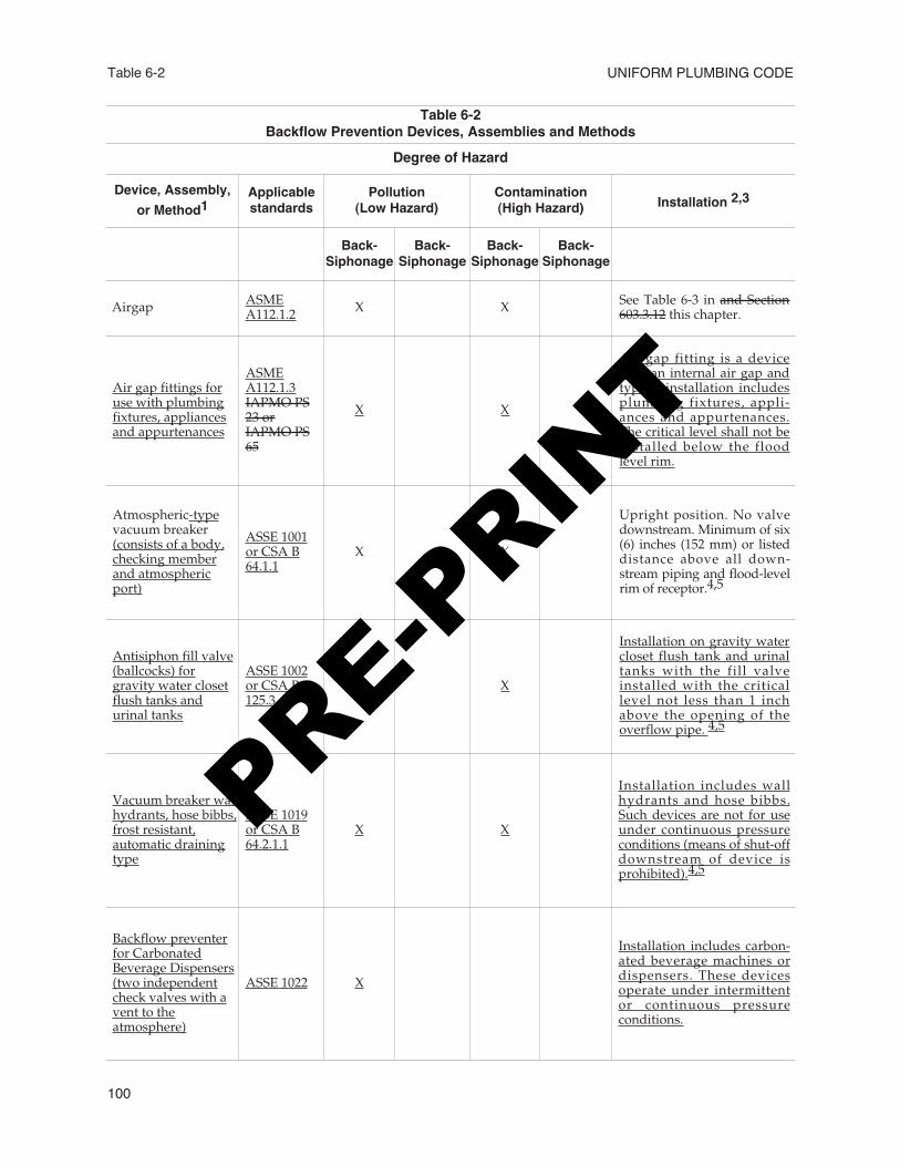
Table 6-2Backflow Prevention Devices, Assemblies and Methods
Degree of Hazard
Device, Assembly,or Method1
Applicablestandards
Pollution(Low Hazard)
Contamination(High Hazard) Installation 2,3
Back-Siphonage
Back-Siphonage
Back-Siphonage
Back-Siphonage
Airgap ASMEA112.1.2 X X See Table 6-3 in and Section
603.3.12 this chapter.
Air gap fittings foruse with plumbingfixtures, appliancesand appurtenances
ASMEA112.1.3IAPMO PS23 orIAPMO PS65
X X
Air gap fitting is a devicewith an internal air gap andtypical installation includesplumbing fixtures, appli-ances and appurtenances.The critical level shall not beinstalled below the floodlevel rim.
Atmospheric-typevacuum breaker(consists of a body,checking memberand atmosphericport)
ASSE 1001or CSA B64.1.1
X X
Upright position. No valvedownstream. Minimum of six(6) inches (152 mm) or listeddistance above all down-stream piping and flood-levelrim of receptor.4,5
Antisiphon fill valve(ballcocks) forgravity water closetflush tanks andurinal tanks
ASSE 1002or CSA B125.3
X X
Installation on gravity watercloset flush tank and urinaltanks with the fill valveinstalled with the criticallevel not less than 1 inchabove the opening of theoverflow pipe. 4,5
Vacuum breaker wallhydrants, hose bibbs,frost resistant,automatic drainingtype
ASSE 1019or CSA B64.2.1.1
X X
Installation includes wallhydrants and hose bibbs.Such devices are not for useunder continuous pressureconditions (means of shut-offdownstream of device isprohibited).4,5
Backflow preventerfor CarbonatedBeverage Dispensers(two independentcheck valves with avent to theatmosphere)
ASSE 1022 X
Installation includes carbon-ated beverage machines ordispensers. These devicesoperate under intermittentor continuous pressureconditions.
PRE-PRIN
T
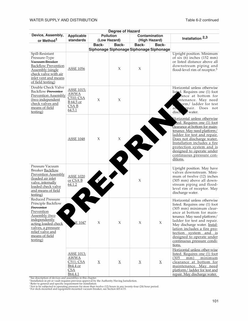
WATER SUPPLY AND DISTRIBUTION Table 6-2 continued
101
Degree of HazardDevice, Assembly,
or Method1Applicablestandards
Pollution(Low Hazard)
Contamination(High Hazard) Installation 2,3
Back-Siphonage
Back-Siphonage
Back-Siphonage
Back-Siphonage
Spill-ResistantPressure-TypeVacuum BreakerBackflow PreventionAssembly (singlecheck valve with airinlet vent and meansof field testing)
ASSE 1056 X X
Upright position. Minimumof six (6) inches (152 mm)or listed distance above alldownstream piping andflood-level rim of receptor.5
Double Check ValveBackflow PreventerPrevention Assembly(two independentcheck valves andmeans of fieldtesting)
ASSE 1015;AWWAC510; CSAB 64.5 orCSA B64.5.1
X X
Horizontal unless otherwiselisted. Requires one (1) footclearance at bottom formaintenance. May needplatform/ ladder for testand repair. Does notdischarge water.
ASSE 1048 X X
Horizontal unless otherwiselisted. Requires one (1) footclearance at bottom for main-tenance. May need platform/ladder for test and repair.Does not discharge water.Installation includes a fireprotection system and isdesigned to operate undercontinuous pressure con-ditions.
Pressure VacuumBreaker BackflowPrevention Assembly(loaded air inletvalve, internallyloaded check valveand means of fieldtesting)
ASSE 1020or CSA B64.1.2
X X
Upright position. May havevalves downstream. Mini-mum of twelve (12) inches(305 mm) above all down-stream piping and flood-level rim of receptor. Maydischarge water.
Reduced PressurePrinciple BackflowPreventerPreventionAssembly (twoindependentlyacting loaded checkvalves, a pressurerelief valve andmeans of fieldtesting)
ASSE 1047 X X X X
Horizontal unless otherwiselisted. Requires one (1) foot(305 mm) minimum clear-ance at bottom for main-tenance. May need platform/ladder for test and repair.May discharge water. Instal-lation includes a fire pro-tection system and isdesigned to operate undercontinuous pressure condi-tions.
ASSE 1013;AWWAC511; CSAB64.4 orCSAB64.4.1
X X X X
Horizontal unless other-wiselisted. Requires one (1) foot(305 mm) minimumclearance at bottom formaintenance. May needplatform/ ladder for test andrepair. May discharge water.
1 See description of devices and assemblies in this chapter.2 Installation in pit or vault requires previous approval by the Authority Having Jurisdiction.3 Refer to general and specific requirement for installation.4 Not to be subjected to operating pressure for more than twelve (12) hours in any twenty-four (24) hour period.5 For deck-mounted and equipment-mounted vacuum breaker, see Section 603.4.15.
PRE-PRIN
T
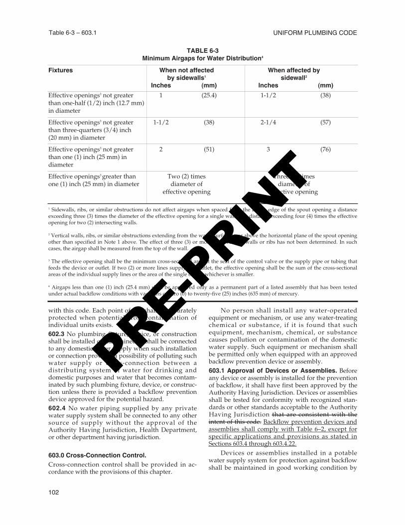
Table 6-3 – 603.1 UNIFORM PLUMBING CODE
102
with this code. Each point of use shall be separatelyprotected when potential cross-contamination ofindividual units exists.602.3 No plumbing fixture, device, or constructionshall be installed or maintained or shall be connectedto any domestic water supply when such installationor connection provides a possibility of polluting suchwater supply or cross-connection between adistributing system of water for drinking anddomestic purposes and water that becomes contam-inated by such plumbing fixture, device, or construc-tion unless there is provided a backflow preventiondevice approved for the potential hazard.602.4 No water piping supplied by any privatewater supply system shall be connected to any othersource of supply without the approval of theAuthority Having Jurisdiction, Health Department,or other department having jurisdiction.
603.0 Cross-Connection Control.Cross-connection control shall be provided in ac-cordance with the provisions of this chapter.
No person shall install any water-operatedequipment or mechanism, or use any water-treatingchemical or substance, if it is found that suchequipment, mechanism, chemical, or substancecauses pollution or contamination of the domesticwater supply. Such equipment or mechanism shallbe permitted only when equipped with an approvedbackflow prevention device or assembly.603.1 Approval of Devices or Assemblies. Beforeany device or assembly is installed for the preventionof backflow, it shall have first been approved by theAuthority Having Jurisdiction. Devices or assembliesshall be tested for conformity with recognized stan-dards or other standards acceptable to the AuthorityHaving Jurisdiction that are consistent with theintent of this code. Backflow prevention devices andassemblies shall comply with Table 6–2, except forspecific applications and provisions as stated inSections 603.4 through 603.4.22.
Devices or assemblies installed in a potablewater supply system for protection against backflowshall be maintained in good working condition by
TABLE 6-3Minimum Airgaps for Water Distribution4
Fixtures When not affected When affected byby sidewalls1 sidewall2
Inches (mm) Inches (mm)Effective openings3 not greater 1 (25.4) 1-1/2 (38)than one-half (1/2) inch (12.7 mm)in diameter
Effective openings3 not greater 1-1/2 (38) 2-1/4 (57)than three-quarters (3/4) inch(20 mm) in diameter
Effective openings3 not greater 2 (51) 3 (76)than one (1) inch (25 mm) indiameter
Effective openings3 greater than Two (2) times Three (3) timesone (1) inch (25 mm) in diameter diameter of diameter of
effective opening effective opening
1 Sidewalls, ribs, or similar obstructions do not affect airgaps when spaced from the inside edge of the spout opening a distanceexceeding three (3) times the diameter of the effective opening for a single wall, or a distance exceeding four (4) times the effectiveopening for two (2) intersecting walls.
2 Vertical walls, ribs, or similar obstructions extending from the water surface to or above the horizontal plane of the spout openingother than specified in Note 1 above. The effect of three (3) or more such vertical walls or ribs has not been determined. In suchcases, the airgap shall be measured from the top of the wall.
3 The effective opening shall be the minimum cross-sectional area at the seat of the control valve or the supply pipe or tubing thatfeeds the device or outlet. If two (2) or more lines supply one outlet, the effective opening shall be the sum of the cross-sectionalareas of the individual supply lines or the area of the single outlet, whichever is smaller.
4 Airgaps less than one (1) inch (25.4 mm) shall be approved only as a permanent part of a listed assembly that has been testedunder actual backflow conditions with vacuums of zero (0) to twenty-five (25) inches (635 mm) of mercury.
PRE-PRIN
T
the person or persons having control of such devicesor assemblies. Such devices or assemblies shall betested at the time of installation, repair, or relocationand not less than on an annual schedule thereafter,or more often when required by the AuthorityHaving Jurisdiction. If found to be defective orinoperative, the device or assembly shall be repairedor replaced. No device or assembly shall be removedfrom use or relocated or other device or assemblysubstituted, without the approval of the AuthorityHaving Jurisdiction.
Testing shall be performed by a certifiedbackflow assembly tester.603.2 Backflow Prevention Devices, Assemblies,and Methods.
603.2.1 Airgap. The minimum airgap to affordbackflow protection shall be in accordance withTable 6-3.
603.2.2 Atmospheric Vacuum Breaker (AVB).An atmospheric vacuum breaker consists of abody, a checking member, and an atmosphericopening port.
603.2.3 Hose Connection Backflow Preventer.A hose connection backflow preventer consists oftwo (2) independent check valves with anindependent atmospheric vent between and ameans of field testing and draining.603.2.4 Double Check Valve Backflow Preven-tion Assembly (DC). A double check valvebackflow prevention assembly consists of two (2)independently acting internally loaded checkvalves, four (4) properly located test cocks, andtwo (2) isolation valves.
603.2.5 Pressure Vacuum Breaker BackflowPrevention Assembly (PVB). A pressurevacuum breaker backflow prevention assemblyconsists of a loaded air inlet valve, an internallyloaded check valve, two (2) properly located testcocks, and two (2) isolation valves. This deviceshall be installed indoors only if provisions forspillage are provided.603.2.6 Pressure Vacuum Breaker Spill-Resistant-Type Backflow PreventionAssembly (SVB). A pressure-type vacuumbreaker backflow prevention assembly consistsof one (1) check valve force-loaded closed andan air inlet vent valve force-loaded open toatmosphere, positioned downstream of the checkvalve, and located between and including two(2) tightly closing shutoff valves and test cocks.603.2.7 Reduced-Pressure Principle BackflowPrevention Assembly (RP). A reduced-pressureprinciple backflow prevention assembly consistsof two (2) independently acting internally
loaded check valves, a differential pressure-reliefvalve, four (4) properly located test cocks, andtwo (2) isolation valves.
603.3 General Requirements.603.3.1 Assemblies shall conform to listedstandards and be acceptable to the AuthorityHaving Jurisdiction, with jurisdiction over theselection and installation of backflow preventionassemblies.603.3.2 Where more than one (1) backflowprevention valve is installed on a single premise,and the valves are installed in one (1) location,each separate valve shall be permanentlyidentified by the permittee in a mannersatisfactory to the Authority Having Jurisdiction.603.3.3 The premise owner or responsibleperson shall have the backflow preventionassembly tested by a certified backflow assemblytester at the time of installation, repair, orrelocation and not less than on an annualschedule thereafter, or more often whenrequired by the Authority Having Jurisdiction.The periodic testing shall be performed inaccordance with the procedures referenced inTable 14-1 by a tester qualified in accordance withthose standards.603.3.4 Access and clearance shall be providedfor the required testing, maintenance, and repair.Access and clearance shall require not less thanof one (1) foot (305 mm) between the lowestportion of the assembly and grade, floor, orplatform. Installations elevated more than five(5) feet (1,524 mm) above the floor or grade shallbe provided with a permanent platform capableof supporting a tester or maintenance person.603.3.5 Direct connections between potablewater piping and sewer-connected wastes shallnot exist under any condition with or withoutbackflow protection. Where potable water isdischarged to the drainage system, it shall be bymeans of an approved airgap of two (2) pipediameters of the supply inlet, but in no case shallthe gap be less than one (1) inch (25 mm).Connection shall be permitted to be made to theinlet side of a trap provided that an approvedvacuum breaker is installed not less than six (6)inches (152 mm), or the distance according to thedevice’s listing, above the flood-level rim of suchtrapped fixture, so that at no time will any suchdevice be subjected to any back-pressure.603.3.6 Backflow preventers for hot waterexceeding 110°F (43.3°C) shall be a typedesigned to operate at temperatures of 110°F(43.3°C) or more without rendering any portionof the assembly inoperative.
WATER SUPPLY AND DISTRIBUTION 603.1 – 603.3
103
PRE-PRIN
T
603.3.7 Fixtures, appliances, or appurtenanceswith integral backflow preventers or integralairgaps manufactured as a unit shall be installedin accordance with their listing requirementsand the manufacturers’ instructions.603.3.8 In cold climate areas, backflowassemblies and devices shall be protected fromfreezing with an outdoor enclosure or by amethod acceptable to the Authority HavingJurisdiction.603.3.9 Drain lines serving backflow devices orassemblies shall be sized in accordance with thedischarge rates of the manufacturer’s flow chartsof such devices or assemblies.603.3.10 Design and Installation of PlumbingFixtures. Plumbing fixtures shall be installedsuch that fixture fittings, complying with thebackflow prevention requirements of ASMEA112.18.1, do not have these requirements com-promised by the designated fixture fittingmounting surface.
603.4 Specific Requirements.603.4.1 Water closet and urinal flushometervalves shall be equipped with an atmosphericvacuum breaker. The vacuum breaker shall beinstalled on the discharge side of theflushometer valve with the critical level not lessthan six (6) inches (152 mm), or the distanceaccording to its listing, above the overflow rimof a water closet bowl or the highest part of aurinal.603.4.2 Water closet and urinal tanks shall beequipped with a ballcock. The ballcock shall beinstalled with the critical level not less than one(1) inch (25.4 mm) above the full opening of theoverflow pipe. In cases where the ballcock hasno hush tube, the bottom of the water supplyinlet shall be installed one (1) inch (25.4 mm)above the full opening of the overflow pipe.603.4.3 Water closet flushometer tanks shall beprotected against backflow by an approvedbackflow prevention assembly, device, ormethod.603.4.4 Heat Exchangers.
603.4.4.1 Heat exchangers used for heattransfer, heat recovery, or solar heating shallprotect the potable water system from beingcontaminated by the heat transfer medium.Single-wall heat exchangers used inindirect-fired water heaters shall meet therequirements of Section 506.4.2. Double-wallheat exchangers shall separate the potablewater from the heat-transfer medi-um byproviding a space between the two (2) wallsthat are vented to the atmosphere.
603.4.5 Water supply inlets to tanks, vats,sumps, swimming pools, and other receptorsshall be protected by one of the followingmeans:(1) An approved airgap.(2) A listed vacuum breaker installed on the
discharge side of the last valve with thecritical level not less than six (6) inches (152mm) or in accordance with its listing.
(3) A backflow preventer suitable for the con-tamination or pollution, installed in accor-dance with the requirements for that type ofdevice or assembly as set forth in thischapter.
603.4.6 Protection from Lawn Sprinklers andIrrigation Systems.
603.4.6.1 Potable water supplies to systemshaving no pumps or connections for pumpingequipment, and no chemical injection orprovisions for chemical injection, shall beprotected from backflow by one of thefollowing devices:(1) Atmospheric vacuum breaker(2) Pressure vacuum breaker(3) Spill-resistant pressure vacuum breaker(4) Reduced-pressure backflow preventer603.4.6.2 Where sprinkler and irrigationsystems have pumps, connections for pumpingequipment, or auxiliary air tanks, or areotherwise capable of creating back-pressure, thepotable water supply shall be protected bythe following type of device if the backflowdevice is located upstream from the sourceof back-pressure:(1) Reduced-pressure backflow preventer603.4.6.3 Where systems have a backflowdevice installed downstream from a potablewater supply pump or a potable water supplypump connection, the device shall be one ofthe following:(1) Atmospheric vacuum breaker(2) Pressure vacuum breaker(3) Spill-resistant pressure vacuum breaker(4) Reduced-pressure backflow preventer603.4.6.4 Where systems include a chemicalinjector or any provisions for chemical injection,the potable water supply shall be protectedby the following:(1) Reduced-pressure backflow preventer
603.4.7 Potable water outlets with hoseattachments, other than water heater drains,boiler drains, and clothes washer connections,shall be protected by a nonremovable hose-bibb-
UNIFORM PLUMBING CODE
104
603.3 – 603.4
PRE-PRIN
T
type backflow preventer, a nonremovable hosebibb-type vacuum breaker, or by an atmosphericvacuum breaker installed not less than six (6)inches (152 mm) above the highest point ofusage located on the discharge side of the lastvalve. In climates where freezing temperaturesoccur, a listed self-draining frost-proof hose bibbwith an integral backflow preventer or vacuumbreaker shall be used.603.4.8 Water-cooled compressors, degreasers,or any other water-cooled equipment shall beprotected by a backflow preventer installed inaccordance with the requirements of thischapter.Note:Water-cooled equipment that produces back-pressure shall be equipped with the appropriateprotection.603.4.9 Water inlets to water-suppliedaspirators shall be equipped with a vacuumbreaker installed in accordance with its listingrequirements and this chapter. The dischargeshall drain through an airgap. When the tail-piece of a fixture to receive the discharge of anaspirator is used, the airgap shall be locatedabove the flood-level rim of the fixture.603.4.10 Potable water makeup connections tosteam or hot water boilers shall be providedwith a listed backflow protection assembly.603.4.11 Nonpotable Water Piping. In caseswhere it is impractical to correct individualcross-connections on the domestic waterline, theline supplying such outlets shall be considered anonpotable water line. No drinking or domesticwater outlets shall be connected to the non-potable waterline. Whenever possible, portionsof the nonpotable waterline shall be exposed,and exposed portions shall be properlyidentified in a manner satisfactory to theAuthority Having Jurisdiction. Each outlet onthe nonpotable waterline that is used fordrinking or domestic purposes shall be posted:“Caution: Nonpotable water, do not drink.”603.4.12 Potable water supply to carbonatorsshall be protected by either an airgap or a ventedbackflow preventer for carbonated beveragedispensers installed within the carbonatedbeverage dispenser. The carbonated beveragedispenser shall bear the label of an approvedtesting agency, certifying and attesting that suchequipment has been tested and inspected andmeets the requirements of the approvedapplicable standard. Carbonated beveragedispensers without an approved internal airgapor vented backflow preventer for carbonatedbeverage dispensers and carbonated beveragedispensing systems shall have the water supplyprotected with a vented backflow preventer forcarbonated beverage dispensers.
603.4.13 Water Treatment Units. Reverseosmosis drinking water treatment units shallmeet the requirements of the applicable stan-dards referenced in Table 14-1. Waste ordischarge from reverse osmosis or other types ofwater treatment units shall enter the drainagesystem through an airgap.603.4.14 Backflow preventers shall not belocated in any area containing fumes that aretoxic, poisonous, or corrosive.603.4.15 Deck-mounted or equipment-mountedvacuum breakers shall be installed in accordancewith their listing and the manufacturer’sinstructions, with the critical level not less thanone (1) inch (25.4 mm) above the flood-level rim.603.4.16 Protection from Fire Systems.
603.4.16.1 Except as provided underSections 603.4.16.2 and 603.4.16.3, potablewater supplies to fire protection systemsthat are normally under pressure, includingbut not limited to standpipes and automaticsprinkler systems, except in one- or two-family residential sprinkler systems, pipedin materials approved for potable waterdistribution systems shall be protected fromback-pressure and back-siphonage by one ofthe following testable devices:(1) Double check valve assembly(2) Double check detector assembly(3) Reduced pressure backflow preventer(4) Reduced pressure detector assembly
Potable water supplies to fire protectionsystems that are not normally underpressure shall be protected from backflowand shall meet the requirements of theappropriate standards referenced in Table14-1.603.4.16.2 Where fire protection systemssupplied from a potable water systeminclude a fire department (siamese) connec-tion that is located less than seventeen-hundred (1,700) feet (518.2 m) from a non-potable water source that could be used bythe fire department as a secondary watersupply, the potable water supply shall beprotected by one of the following:(1) Reduced pressure backflow preventor(2) Reduced pressure detector assemblyNote:Nonpotable water sources include firedepartment vehicles carrying water of ques-tionable quality or water that is treated withantifreeze, corrosion inhibitors, orextinguishing agents.
WATER SUPPLY AND DISTRIBUTION
105
603.4
PRE-PRIN
T
603.4.16.3 Where antifreeze, corrosioninhibitors, or other chemicals are added to afire protection system supplied from apotable water supply, the potable watersystem shall be protected by one of thefollowing:(1) Reduced pressure backflow preventer(2) Reduced pressure detector assembly603.4.16.4 Whenever a backflow device isinstalled in the potable water supply to afire protection system, the hydraulic designof the system shall account for the pressuredrop through the backflow device. If suchdevices are retrofitted for an existing fireprotection system, the hydraulics of thesprinkler system design shall be checked toverify that there will be sufficient waterpressure available for satisfactory operationof the fire sprinklers.603.4.16.5 Residential Sprinkler Systems.When residential sprinkler systems areinstalled using the potable water system,they shall be installed in accordance withthe standards listed in Table 14-1.
603.4.17 Special Equipment, Water SupplyProtection. Vacuum breakers for washer-hosebedpans shall be located not less than five (5)feet (1,524 mm) above the floor. Hoseconnections in health care or laboratory areasshall be not less than six (6) feet (1,829 mm)above the floor.603.4.18 Portable cleaning equipment, dentalvacuum pumps, and chemical dispensers shallbe protected from backflow by an airgap, anatmospheric vacuum breaker, a spill-proofvacuum breaker, or a reduced pressure principlebackflow preventer.603.4.19 Water Heater Connectors. Flexiblemetallic water heater connectors or reinforcedflexible water heater connectors connectingwater heaters to the piping system shall be incompliance with the appropriate standardslisted in Table 14-1.603.4.2019 Combination stop-and-waste valvesor cocks shall not be installed underground.603.4.20 Pure Water Process Systems. Thewater supply to a pure water process system,such as dialysis water systems, semiconductorwashing systems, and similar process pipingsystems, shall be protected from back-pressureand back-siphonage by a reduced-pressureprinciple backflow preventer.
603.4.20.1 Dialysis Water Systems. Theindividual connections of the dialysisrelated equipment to the dialysis pure watersystem shall not require additional backflowprotection.
603.4.221 Plumbing Fixture Fittings.Plumbing fixture fittings with integral backflowprotection shall comply with ASME A112.18.1.603.4.22 Potable water supply to swimmingpools, spas and hot tubs shall be protected by anairgap or a reduced pressure principle backflowpreventer in accordance with the following:(1) The unit is equipped with a submerged fillline; or(2) The potable water supply is directlyconnected to the unit circulation system.
604.0 Materials.604.1 Pipe, tube, and fittings carrying water used inpotable water systems intended to supply drinkingwater shall meet the requirements of NSF 61 asfound in Table 14-1. Materials used in the watersupply system, except valves and similar devices,shall be of a like material, except where otherwiseapproved by the Authority Having Jurisdiction.
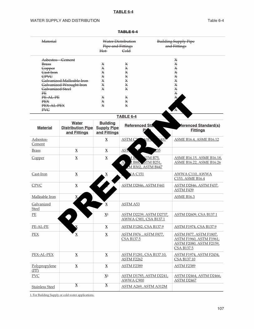
Materials for building water piping and buildingsupply piping shall be in accordance with theapplicable standards referenced in Table 6-4. and thestandards in Table 14-1.604.2 Copper tube for water piping shall have aweight of not less than Type L.
Exception: Type M copper tubing shall bepermitted to be used for water piping whenpiping is above ground in, or on, a building orunderground outside of structures.
604.3 Hard-drawn copper tubing for water supplyand distribution in addition to the required incisedmarking, shall be marked in accordance with ASTMB 88 Seamless Copper Water Tube as referenced inTable 14-1. The colors shall be: Type K, green; TypeL, blue; Type M, red.604.4 Listed flexible copper water connectors shallbe installed in readily accessible locations, unlessotherwise listed.604.5 Cast-iron fittings up to and including two (2)inches (51 mm) in size, when used in connectionwith potable water piping, shall be galvanized.604.6 Malleable iron water fittings shall begalvanized.604.7 Piping and tubing that has previously beenused for any purpose other than for potable watersystems shall not be used.604.8 Approved plastic materials shall be permittedto be used in water service piping, provided thatwhere metal water service piping is used forelectrical grounding purposes, replacement pipingtherefore shall be of like materials.
Exception: Where a grounding system acceptableto the Authority Having Jurisdiction is installed,
603.4 – 604.8 UNIFORM PLUMBING CODE
106
PRE-PRIN
T
WATER SUPPLY AND DISTRIBUTION
107
Table 6-4
TABLE 6-4
Material Water Distribution Building Supply PipePipe and Fittings and Fittings
Hot Cold
Asbestos – Cement XBrass X X XCopper X X XCast Iron X X XCPVC X X XGalvanized Malleable Iron X X XGalvanized Wrought Iron X X XGalvanized Steel X X XPE XPE-AL-PE X X XPEX X X XPEX-AL-PEX X X XPVC X
TABLE 6-4
MaterialWater
Distribution Pipeand Fittings
BuildingSupply Pipeand Fittings
Referenced Standard(s)Pipe
Referenced Standard(s)Fittings
Asbestos-Cement
X ASTM C296, AWWA C400 ASME B16.4, ASME B16.12
Brass X X ASTM B43, ASTM B135
Copper X X ASTM B42, ASTM B75,ASTM B88, ASTM B251,ASTM B302, ASTM B447
ASME B16.15, ASME B16.18,ASME B16.22, ASME B16.26
Cast-Iron X X AWWA C151 AWWA C110, AWWAC153, ASME B16.4
CPVC X X ASTM D2846, ASTM F441 ASTM D2846, ASTM F437,ASTM F439
Malleable Iron X X ASME B16.3
GalvanizedSteel
X X ASTM A53
PE X1 ASTM D2239, ASTM D2737,AWWA C901, CSA B137.1
ASTM D2609, CSA B137.1
PE-AL-PE X X ASTM F1282, CSA B137.9 ASTM F1974, CSA B137.9
PEX X X ASTM F876 , ASTM F877,CSA B137.5
ASTM F877, ASTM F1807,ASTM F1960, ASTM F1961,ASTM F2080, ASTM F2159,CSA B137.5
PEX-AL-PEX X X ASTM F1281, CSA B137.10,ASTM F2262
ASTM F1974, ASTM F2434,CSA B137.10
Polypropylene(PP)
X X ASTM F2389 ASTM F2389
PVC X1 ASTM D1785, ASTM D2241,AWWA C900
ASTM D2464, ASTM D2466,ASTM D2467
Stainless Steel X X ASTM A269, ASTM A312M
1. For Building Supply or cold-water applications.
TABLE 6-4
PRE-PRIN
T
inspected, and approved, metallic pipe shall bepermitted to be replaced with nonmetallic pipe.Plastic materials for water service piping outsideunderground shall have a blue insulated coppertracer wire or other approved conductorinstalled adjacent to the piping. Access shall beprovided to the tracer wire or the tracer wireshall terminate above ground at each end of thenonmetallic piping. The tracer wire size shall benot less than 18 AWG and the insulation typeshall be suitable for direct burial.
604.9 Solder shall conform to the requirements ofSection 316.1.3.604.10 Water pipe and fittings with a lead contentwhich exceeds eight (8) percent shall be prohibited inpiping systems used to convey potable water.604.11 PEX. Cross-linked polyethylene (PEX) tubingconforming to ASTM F877 shall be marked with theappropriate standard designation(s) listed in Table14-1 for which the tubing has been approved. for thefittings specified for use with the tubing. Such mark-ing shall not be required for PEX tubing conformingto only ASTM F876. PEX tubing shall be installed incompliance with the provisions of this section.
604.11.1 PEX Fittings. Metal insert fittings,metal compression fittings, and cold expansionfFittings used with PEX tubing shall be manu-factured to and marked in accordance with thestandards for the fittings referenced in Table 14-1.604.11.2 Water Heater Connections. PEXtubing shall not be installed within the first eigh-teen (18) inches (457 mm) of piping connected toa water heater.
604.12 Flexible Corrugated Connectors. Flexiblecorrugated connectors of copper or stainless steelshall be limited to the following connector lengths:
Water Heater Connectors – twenty-four (24)inches (609 mm).Fixture Connectors – thirty (30) inches (762mm).Washing Machine Connectors – seventy-two(72) inches (1,827 mm).Dishwasher and Icemaker Connectors – one-hundred and twenty (120) inches (3,048 mm).
604.13 PEX-AL-PEX and PE-AL-PE. Crosslinkedpolyethylene-aluminum-crosslinked polyethylene(PEX-AL-PEX) and polyethylene-aluminum-polyethylene (PE-AL-PE) composite pipe shall bemarked with the applicable standard referenced inTable 14-1 for which the piping has been listed orapproved. PEX-AL-PEX and PE-AL-PE piping shallbe installed in compliance with the provisions of thissection.
604.13.1 PEX-AL-PEX and PE-AL-PE. Fittingsused with PEX-AL-PEX and PE-AL-PE pipingshall be manufactured to and marked in accor-dance with the standard for the fittingsreferenced in Table 14-1.
604.13.2 Water Heater Connections. PEX-AL-PEX or PE-AL-PE tubing shall not be installedwithin the first eighteen (18) inches (457 mm) ofpiping connected to a water heater.
604.14 Polypropylene (PP). Polypropylene (PP)piping shall be marked with the applicable standardreferenced in Table 14–1 for which the piping hasbeen approved. Polypropylene (PP) piping shall beinstalled in compliance with the provisions of thissection.
604.14.1 Heat-Fusion Joints. Heat-fusion jointsfor polypropylene (PP) pipe and fitting jointsshall be installed with socket type heat-fusedpolypropylene fittings, butt-fusion polyprop-ylene fittings or pipe, or electro-fusion polyprop-ylene fittings. Joint surfaces shall be clean andfree from moisture. The joint shall beundisturbed until cool. Joints shall be made inaccordance with ASTM F 2389.
604.14.2 Mechanical and CompressionSleeve Joints. Mechanical and compressionsleeve joints shall be installed in accordance withthe manufacturer’s instructions.
604.145 Water Heater Connectors. Flexible metal-lic water heater connectors or reinforced flexiblewater heater connectors connecting water heating tothe piping system shall be in compliance with theapplicable standards referenced in Table 14-1.
605.0 Valves.605.1 Valves up to and including two (2) inches (51mm) in size shall be brass or other approvedmaterial. Sizes exceeding two (2) inches (51 mm)shall be permitted to have cast-iron or brass bodies.Each gate or ball valve shall be a fullway type withworking parts of non-corrosive material. Valvescarrying water used in potable water systemsintended to supply drinking water shall meet therequirements of NSF 61 as referenced in Table 14–1.605.2 A fullway valve controlling outlets shall beinstalled on the discharge side of each water meterand on each unmetered water supply. Water pipingsupplying more than one (1) building on any one (1)premises shall be equipped with a separate fullwayvalve to each building, so arranged that the watersupply can be turned on or off to any individual orseparate building provided; however, that supplypiping to a single-family residence and buildingaccessory thereto shall be permitted to be controlledon one (1) valve. Such shutoff valves shall beaccessible at all times. A fullway valve shall beinstalled on the discharge piping from water supplytanks at or near the tank. A fullway valve shall beinstalled on the cold water supply pipe to each waterheater at or near the water heater.
UNIFORM PLUMBING CODE
108
604.8 – 605.2
PRE-PRIN
T
605.3 In multidwelling units, one (1) or more shutoffvalves shall be provided in each dwelling unit sothat the water supply to any plumbing fixture orgroup of fixtures in that dwelling unit can be shut offwithout stopping water supply to fixtures in otherdwelling units. These valves shall be accessible in thedwelling unit that they control.605.4 Valves used to control two (2) or moreopenings shall be fullway gate valves, ball valves, orother approved valves designed and approved forthe service intended.605.5 A control valve shall be installed immediatelyahead of each water-supplied appliance andimmediately ahead of each slip joint or appliancesupply.
Parallel water distribution systems shall providea control valve either immediately ahead of eachfixture being supplied or installed at the manifoldand shall be identified with the fixture beingsupplied.605.6 Required shutoff or control valves shall beaccessible.605.7 A single control valve shall be installed on awater supply line ahead of any automatic meteringvalve that supplies a battery of fixtures.
606.0 Joints and Connections.606.1 Types of Joints.
606.1.1 Flared Joints. Flared joints for softcopper water tubing shall be made with fittingsmeeting approved standards. The tubing shallbe reamed to the full bore, resized to round, andexpanded with a proper flaring tool.606.1.2 Mechanical Joints. Mechanical jointsfor cast-iron water pipe shall conform to nation-ally recognized standards.606.1.3 Mechanically Formed Tee Fittings.Mechanically extracted collars shall be formed ina continuous operation consisting of drilling apilot hole and drawing out the tube surface toform a collar having a height not less than three(3) times the thickness of the branch tube wall.
The branch tube shall be notched to conformwith the inner curve of the run tube and shallhave two (2) dimple/depth stops to ensure thatpenetration of the branch tube into the collar isof sufficient depth for brazing and that thebranch tube does not obstruct the flow in themain line tube. Dimple/depth stops shall be inline with the run of the tube. The second dimpleshall be one-quarter (1/4) inch (6.35 mm) abovethe first and shall serve as a visual point ofinspection.
Joints shall be brazed in accordance withSection 316.1.7. Soldered joints shall not beallowed.
606.2 Use of Joints.606.2.1 Copper Water Tube. Joints in coppertubing shall be made by the appropriate use ofapproved fittings properly soldered or brazedtogether as provided in Section 316.1.3 or 316.1.7or by means of approved flared or compressionfittings in Section 606.1.1 or 316.1.5. Solder andsoldering flux shall conform to the requirementsof Section 316.1.3. Mechanically formed teefittings shall be made by brazing only and shallconform to the requirements of Section 316.1.7.606.2.2 Plastic Fittings. Female PVC screwedfittings for water piping shall be used withplastic male fittings and plastic male threadsonly.606.2.3 Slip Joints. In water piping, slip jointsshall be permitted to be used only on theexposed fixture supply.
607.0 Gravity Supply Tanks.Gravity tanks for potable water shall be tightlycovered, and have not less than a sixteen (16) square-inch (10,323 mm2) overflow screened with copperscreen having not less than fourteen (14) norexceeding eighteen (18) openings per linear inch(25.4 mm).
608.0 Water Pressure, Pressure Regulators,Pressure Relief Valves, and Vacuum ReliefValves.608.1 Inadequate Water Pressure. Whenever thewater pressure in the main or other source of supplywill not provide a residual water pressure of not lessthan fifteen (15) pounds per square inch (103.4 kPa),after allowing for friction and other pressure losses, atank and a pump or other means that will providesaid fifteen (15) pound (103.4 kPa) pressure shall beinstalled. Whenever fixtures and/or fixture fittingsare installed that require residual pressure exceedingfifteen (15) pounds per square inch (103.4 kPa), thatminimum residual pressure shall be provided.608.2 Excessive Water Pressure. Where staticwater pressure in the water supply piping isexceeding eighty (80) pounds per square inch (552kPa), an approved-type pressure regulator precededby an adequate strainer shall be installed and thestatic pressure reduced to eighty (80) pounds persquare inch (552 kPa) or less. Pressure regulator(s)equal to or exceeding one and one-half (1-1/2) inchesshall not require a strainer. Such regulator(s) shallcontrol the pressure to all water outlets in thebuilding unless otherwise approved by theAuthority Having Jurisdiction. Each such regulatorand strainer shall be accessibly located above groundor in a vault equipped with a properly sized andsloped bore-sighted drain to daylight, shall be
WATER SUPPLY AND DISTRIBUTION
109
605.3 – 608.2
PRE-PRIN
T
protected from freezing, and shall have the strainerreadily accessible for cleaning without removing theregulator or strainer body or disconnecting thesupply piping. Pipe size determinations shall bebased on 80 percent of the reduced pressure whenusing Table 6-6. An approved expansion tank shallbe installed in the cold water distribution pipingdownstream of each such regulator to preventexcessive pressure from developing due to thermalexpansion and to maintain the pressure setting of theregulator. The expansion tank shall be properly sizedand installed in accordance with the manufacturer’sinstructions and listing. Systems designed byregistered engineers shall be permitted to useapproved pressure relief valves in lieu of expansiontanks provided such relief valves have a maximumpressure relief setting of one-hundred (100) poundsper square inch (689 kPa) or less.608.3 Any water system provided with a checkvalve, backflow preventer, or any other normallyclosed device that prevents dissipation of buildingpressure back into the water main shall be providedwith an approved, listed, and adequately sizedexpansion tank or other approved device having asimilar function to control thermal expansion. Suchexpansion tank or other approved device shall beinstalled on the building side of the check valve,backflow preventer, or other device and shall besized and installed in accordance with the manu-facturer’s recommendation.
Any water system containing storage waterheating equipment shall be provided with anapproved, listed, adequately sized combinationpressure and temperature relief valve, except forlisted nonstorage instantaneous heaters having aninside diameter of not more than three (3) inches (80mm). Each such approved combination temperatureand pressure relief valve shall be installed on thewater-heating device in an approved location basedon its listing requirements and the manufacturer'sinstructions. Each such combination temperatureand pressure relief valve shall be provided with adrain as required in Section 608.5.608.4 Each pressure relief valve shall be anapproved automatic type with drain, and each suchrelief valve shall be set at a pressure of not more thanone-hundred and fifty (150) pounds per square inch(1,035 kPa). No shutoff valve shall be installedbetween the relief valve and the system or in thedrain line.608.5 Relief valves located inside a building shall beprovided with a drain, not smaller than the reliefvalve outlet, of galvanized steel, hard-drawn copperpiping and fittings, CPVC, Polypropylene (PP), orlisted relief valve drain tube with fittings that willnot reduce the internal bore of the pipe or tubing(straight lengths as opposed to coils) and shallextend from the valve to the outside of the building,
with the end of the pipe not more than two (2) feet(610 mm) nor less than six (6) inches (152 mm) aboveground or the flood level of the area receiving thedischarge and pointing downward. Such drains shallbe permitted to terminate at other approvedlocations. Relief valve drains shall not terminate in abuilding’s crawl space. No part of such drain pipeshall be trapped or subject to freezing. The terminalend of the drain pipe shall not be threaded.608.6 Any water-heating device connected to aseparate storage tank and having valves betweensaid heater and tank shall be provided with anapproved water pressure relief valve.608.7 Vacuum Relief Valves. Where a hot-waterstorage tank or an indirect water heater is located atan elevation above the fixture outlets in the hot-water system, a vacuum relief valve shall be installedon the storage tank or heater.
609.0 Installation, Testing, Unions, and Location.609.1 Installation. Water piping shall be adequatelysupported in accordance with Section 314.0. Burredends shall be reamed to the full bore of the pipe ortube. Changes in direction shall be made by theappropriate use of fittings, except that changes indirection in copper tubing may be made with bends,provided that such bends are made with bendingequipment that does not deform or create a loss inthe cross-sectional area of the tubing. Changes indirection are allowed with flexible pipe and tubingwithout fittings in accordance with themanufacturer's installation instructions. Provisionsshall be made for expansion in hot-water piping.Piping, equipment, appurtenances, and devices shallbe installed in a workmanlike manner in conformitywith the provisions and intent of the code. Waterservice yard piping shall be not less than twelve (12)inches (305 mm) below the average local frost depth.The cover shall be not less than twelve (12) inches(305 mm) below finish grade.609.2 Water pipes shall not be run or laid in thesame trench as building sewer or drainage pipingconstructed of clay or materials that are notapproved for use within a building unless both ofthe following conditions are met:
609.2.1 The bottom of the water pipe, at allpoints, shall be not less than twelve (12) inches(305 mm) above the top of the sewer or drainline.609.2.2 The water pipe shall be placed on a solidshelf excavated at one (1) side of the commontrench with a clear horizontal distance of not lessthan twelve (12) inches (305 mm) from the seweror drain line.
Water pipes crossing sewer or drainagepiping constructed of clay or materials that are
UNIFORM PLUMBING CODE
110
608.2 – 609.2
PRE-PRIN
T
not approved for use within a building shall belaid not less than twelve (12) inches (305 mm)above the sewer or drain pipe.
609.3 Water piping installed within a building andin or under a concrete floor slab resting on theground shall be installed in accordance with thefollowing requirements:
609.3.1 Ferrous piping shall have a protectivecoating of an approved type, machine appliedand conforming to recognized standards. Fieldwrapping shall provide equivalent protectionand shall be restricted to those short sectionsand fittings necessarily stripped for threading.Zinc coating (galvanizing) shall not be deemedadequate protection for piping or fittings.Approved nonferrous piping shall not berequired to be wrapped.609.3.2 Copper tubing shall be installed withoutjoints where possible. Where joints arepermitted, they shall be brazed, and fittings shallbe wrought copper.Note: For the purpose of this section, “within thebuilding” shall mean within the fixed limits ofthe building foundation.
609.4 Testing. Upon completion of a section or ofthe entire hot and cold water supply system, it shallbe tested and proved tight under a water pressurenot less than the working pressure under which it isto be used. The water used for tests shall be obtainedfrom a potable source of supply. Except for plasticpiping, a fifty (50) pound-per-square-inch (344.5 kPa)air pressure shall be permitted to be substituted forthe water test. In either method of test, the pipingshall withstand the test without leaking for a periodof not less than fifteen (15) minutes.609.5 Unions. Unions shall be installed in the watersupply piping not more than twelve (12) inches (305mm) of regulating equipment, water heating,conditioning tanks, and similar equipment thatrequires service by removal or replacement in amanner that will facilitate its ready removal.609.6 Location. Except as provided in Section 609.7,no building supply shall be located in any lot otherthan the lot that is the site of the building orstructure served by such building supply.609.7 Nothing contained in this code shall beconstrued to prohibit the use of all or part of anabutting lot to:
609.7.1 Provide access to connect a buildingsupply to an available public water service whenproper cause and legal easement not in violationof other requirements have been first establishedto the satisfaction of the Authority HavingJurisdiction.609.7.2 Provide additional space for a buildingsupply when proper cause, transfer of owner-ship, or change of boundary not in violation of
other requirements have been first established tothe satisfaction of the Authority HavingJurisdiction. The instrument recording suchaction shall constitute an agreement with theAuthority Having Jurisdiction, which shallclearly state and show that the areas so joined orused shall be maintained as a unit during thetime they are so used. Such an agreement shallbe recorded in the office of the County Recorderas a part of the conditions of ownership of saidproperties, and shall be binding on heirs,successors, and assigns to such properties. Acopy of the instrument recording such proceed-ings shall be filed with the Authority HavingJurisdiction.
609.8 Low-Pressure Cutoff Required on BoosterPumps for Water Distribution Systems. When abooster pump – excluding a fire pump – is connectedto a water service or underground water pipe, a low-pressure cutoff switch on the inlet side of the pumpshall be installed not more than five (5) feet (1,524mm) of the inlet. The cutoff switch shall be set for notless than ten (10) psi (68.9 kPa). A pressure gaugeshall be installed between the shutoff valve and thepump.609.9 Disinfection of Potable Water System. Newor repaired potable water systems shall be disinfectedprior to use whenever required by the AuthorityHaving Jurisdiction. The method to be followed shallbe that prescribed by the Health Authority or, in caseno method is prescribed by it, the following:
609.9.1 The pipe system shall be flushed withclean, potable water until only potable waterappears at the points of outlet.609.9.2 The system or parts thereof shall befilled with a water-chlorine solution containingnot less than fifty (50) parts per million ofchlorine, and the system or part thereof shall bevalved-off and allowed to stand for twenty-four(24) hours; or, the system or part thereof shall befilled with a water-chlorine solution containing notless than two-hundred (200) parts per million ofchlorine and allowed to stand for three (3) hours.609.9.3 Following the allowed standing time,the system shall be flushed with clean, potablewater until the chlorine residual in the watercoming from the system does not exceed thechlorine residual in the flushing water.609.9.4 The procedure shall be repeated if it isshown by bacteriological examination made byan approved agency that contamination persistsin the system.
609.10 Water Hammer. Building water supplysystems in which where quick-acting valves areinstalled shall be provided with devices waterhammer arrester(s) to absorb the hammer caused byhigh pressures resulting from the quick closing of
WATER SUPPLY AND DISTRIBUTION 609.2 – 609.10
111
PRE-PRIN
T
these valves. These pressure-absorbing devicesWater hammer arrestors shall be approved mechan-ical devices in accordance with the applicablestandard(s) referenced in Table 14-1 and Waterpressure-absorbing devices shall be installed as closeas possible to quick-acting valves.
609.10.1 Mechanical Devices. When listedmechanical devices are used, the manufacturer’sspecifications as to location and method ofinstallation shall be followed.
610.0 Size of Potable Water Piping.610.1 The size of each water meter and each potablewater supply pipe from the meter or other source ofsupply to the fixture supply branches, risers,fixtures, connections, outlets, or other uses shall bebased on the total demand and shall be determinedaccording to the methods and procedures outlinedin this section. Water piping systems shall bedesigned to ensure that the maximum velocitiesallowed by the code and the applicable standard arenot exceeded.610.2 Whenever a water filter, water softener,backflow prevention device, tankless water heater,or similar device is installed in any water supplyline, the pressure loss through such devices shall beincluded in the pressure loss calculations of thesystem, and the water supply pipe and meter shallbe adequately sized to provide for any such pressureloss.
No water filter, water softener, backflowprevention device, or similar device regulated by thiscode shall be installed in any potable water supplypiping when the installation of such device producesan excessive pressure drop in any such water supplypiping. In the absence of specific pressure dropinformation, the diameter of the inlet or outlet of anysuch device or its connecting piping shall be not lessthan the diameter of such water distribution pipingto the fixtures served by the device.
Such devices shall be of a type approved by theAuthority Having Jurisdiction and shall be tested forflow rating and pressure loss by an approvedlaboratory or recognized testing agency to standardsconsistent with the intent of this chapter.610.3 The quantity of water required to be suppliedto every plumbing fixture shall be represented byfixture units, as shown in Table 6-5. Equivalentfixture values shown in Table 6-5 include both hotand cold water demand.610.4 Systems within the range of Table 6-6 shall bepermitted to be sized from that table or by themethod set forth in Section 610.5.
Listed parallel water distribution systems shallbe installed in accordance with their listing, but at no
time shall any portion of the system exceed themaximum velocities allowed by the code.610.5 Except as provided in Section 610.4, the size ofeach water piping system shall be determined inaccordance with the procedure set forth in AppendixA. For alternate methods of sizing water supplysystems, see Appendix L.610.6 Except where the type of pipe used and thewater characteristics are such that no decrease incapacity due to length of service (age of system) isexpected, friction-loss data shall be obtained fromthe “Fairly Rough” or “Rough” charts in AppendixA of this code. Friction or pressure losses in watermeter, valve, and fittings shall be obtained from thesame sources. Pressure losses through water-treatingequipment, backflow prevention devices, or otherflow-restricting devices shall be computed asrequired by Section 610.2.610.7 On any proposed water piping installationsized using Table 6-6, the following conditions shallbe determined:
(1) Total number of fixture units as determinedfrom Table 6-5, Equivalent Fixture Units, forthe fixtures to be installed.
(2) Developed length of supply pipe from meterto most remote outlet.
(3) Difference in elevation between the meter orother source of supply and the highestfixture or outlet.
(4) Pressure in the street main or other source ofsupply at the locality where the installationis to be made.
(5) In localities where there is a fluctuation ofpressure in the main throughout the day,the water piping system shall be designedon the basis of the minimum pressureavailable.
610.8 Size of Meter and Building Supply PipeUsing Table 6-6. The size of the meter and thebuilding supply pipe shall be determined as follows:
(1) Determine the available pressure at thewater meter or other source of supply.
(2) Subtract one-half (1/2) pound per squareinch pressure (3.4 kPa) for each foot (305mm) of difference in elevation between suchsource of supply and the highest water supplyoutlet in the building or on the premises.
(3) Use the “pressure range” group withinwhich this pressure will fall using Table 6-6.
(4) Select the “length” column that is equal to orlonger than the required length.
(5) Follow down the column to a fixture unitvalue equal to or exceeding the total numberof fixture units required by the installation.
UNIFORM PLUMBING CODE
112
609.10 – 610.8
PRE-PRIN
T
(6) Having located the proper fixture unit valuefor the required length, sizes of meter andbuilding supply pipe as found in the two (2)left-hand columns shall be applied.No building supply pipe shall be less than
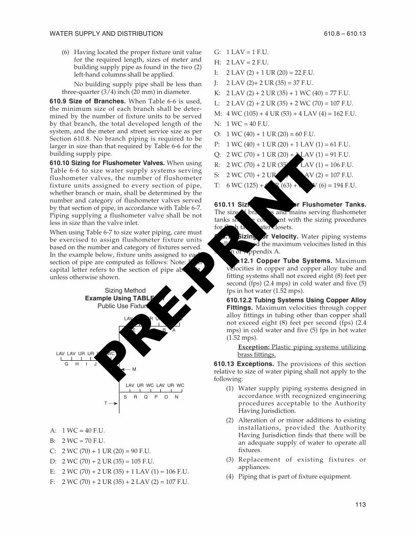
three-quarter (3/4) inch (20 mm) in diameter.610.9 Size of Branches. When Table 6-6 is used,the minimum size of each branch shall be deter-mined by the number of fixture units to be servedby that branch, the total developed length of thesystem, and the meter and street service size as perSection 610.8. No branch piping is required to belarger in size than that required by Table 6-6 for thebuilding supply pipe.610.10 Sizing for Flushometer Valves. When usingTable 6-6 to size water supply systems servingflushometer valves, the number of flushometerfixture units assigned to every section of pipe,whether branch or main, shall be determined by thenumber and category of flushometer valves servedby that section of pipe, in accordance with Table 6-7.Piping supplying a flushometer valve shall be notless in size than the valve inlet.When using Table 6-7 to size water piping, care mustbe exercised to assign flushometer fixture unitsbased on the number and category of fixtures served.In the example below, fixture units assigned to eachsection of pipe are computed as follows: Note: Eachcapital letter refers to the section of pipe above it,unless otherwise shown.
A: 1 WC = 40 F.U.
B: 2 WC = 70 F.U.
C: 2 WC (70) + 1 UR (20) = 90 F.U.
D: 2 WC (70) + 2 UR (35) = 105 F.U.
E: 2 WC (70) + 2 UR (35) + 1 LAV (1) = 106 F.U.
F: 2 WC (70) + 2 UR (35) + 2 LAV (2) = 107 F.U.
G: 1 LAV = 1 F.U.
H: 2 LAV = 2 F.U.
I: 2 LAV (2) + 1 UR (20) = 22 F.U.
J: 2 LAV (2)+ 2 UR (35) = 37 F.U.
K: 2 LAV (2) + 2 UR (35) + 1 WC (40) = 77 F.U.
L: 2 LAV (2) + 2 UR (35) + 2 WC (70) = 107 F.U.
M: 4 WC (105) + 4 UR (53) + 4 LAV (4) = 162 F.U.
N: 1 WC = 40 F.U.
O: 1 WC (40) + 1 UR (20) = 60 F.U.
P: 1 WC (40) + 1 UR (20) + 1 LAV (1) = 61 F.U.
Q: 2 WC (70) + 1 UR (20) + 1 LAV (1) = 91 F.U.
R: 2 WC (70) + 2 UR (35) + 1 LAV (1) = 106 F.U.
S: 2 WC (70) + 2 UR (35) + 2 LAV (2) = 107 F.U.
T: 6 WC (125) + 6 UR (63) + 6 LAV (6) = 194 F.U.
610.11 Sizing Systems for Flushometer Tanks.The size of branches and mains serving flushometertanks shall be consistent with the sizing proceduresfor flush tank water closets.610.12 Sizing for Velocity. Water piping systemsshall not exceed the maximum velocities listed in thissection or Appendix A.
610.12.1 Copper Tube Systems. Maximumvelocities in copper and copper alloy tube andfitting systems shall not exceed eight (8) feet persecond (fps) (2.4 mps) in cold water and five (5)fps in hot water (1.52 mps).610.12.2 Tubing Systems Using Copper AlloyFittings. Maximum velocities through copperalloy fittings in tubing other than copper shallnot exceed eight (8) feet per second (fps) (2.4mps) in cold water and five (5) fps in hot water(1.52 mps).
Exception: Plastic piping systems utilizingbrass fittings.
610.13 Exceptions. The provisions of this sectionrelative to size of water piping shall not apply to thefollowing:
(1) Water supply piping systems designed inaccordance with recognized engineeringprocedures acceptable to the AuthorityHaving Jurisdiction.
(2) Alteration of or minor additions to existinginstallations, provided the AuthorityHaving Jurisdiction finds that there will bean adequate supply of water to operate allfixtures.
(3) Replacement of existing fixtures orappliances.
(4) Piping that is part of fixture equipment.
WATER SUPPLY AND DISTRIBUTION 610.8 – 610.13
113
LAV LAV UR UR WC WC
LAV LAV UR UR WC WC
LAV UR WC LAV UR WC
T
M
F E D C B A
S R Q P O N
G H I J K L
Sizing MethodExample Using TABLE 6-7
Public Use Fixtures
PRE-PRIN
T
(5) Unusual conditions where, in the judgmentof the Authority Having Jurisdiction, anadequate supply of water is provided tooperate fixtures and equipment.
(6) Nonpotable waterlines as defined inSections 601.2.2 and 601.2.3.
(7) The size and material of irrigation waterpiping installed outside of any building orstructure and separated from the potablewater supply by means of an approvedairgap or backflow prevention device is notregulated by this code. The potable waterpiping system supplying each suchirrigation system shall be adequately sizedas required elsewhere in this chapter todeliver the full connected demand of boththe domestic use and the irrigation systems.
611.0 Drinking Water Treatment Units.611.1 Compliance with Standard. Drinking watertreatment units shall meet the requirements of theappropriate standard referenced in Table 14-1.611.2 Airgap Discharge. Discharge from drinkingwater treatment units shall enter the drainage systemthrough an airgap or an airgap device that meets therequirements of the appropriate standardsreferenced in Table 14-1.611.3 Connection Tubing. The tubing to and fromdrinking water treatment units shall be of a size andmaterial as recommended by the manufacturer. Thetubing shall comply with the requirements of theappropriate standards referenced in Table 14-1.611.4 Sizing of Residential Softeners. Residential-use water softeners shall be sized per Table 6-8.
UNIFORM PLUMBING CODE
114
610.13 – 611.4
PRE-PRIN
T

WATER SUPPLY AND DISTRIBUTION
115
Table 6-5
TABLE 6-5Water Supply Fixture Units (WSFU) and Minimum Fixture Branch Pipe Sizes3
MinimumFixture Branch Private Public Assembly6
Appliances, Appurtenances or Fixtures2 Pipe Size1,4Bathtub or Combination Bath/Shower (fill) ................................... 1/2" 4.0 4.03/4'' Bathtub Fill Valve .............................................................. 3/4” 10.0 10.0
Bidet ............................................................................................. 1/2" 1.0Clothes washer............................................................................. 1/2" 4.0 4.0Dental Unit, cuspidor .................................................................... 1/2" 1.0Dishwasher, domestic .................................................................. 1/2" 1.5 1.5Drinking Fountain or Watercooler................................................. 1/2" 0.5 0.5 0.75Hose Bibb ..................................................................................... 1/2" 2.5 2.5Hose Bibb, each additional8 .......................................................... 1/2" 1.0 1.0Lavatory........................................................................................ 1/2" 1.0 1.0 1.0Lawn Sprinkler, each head5 .......................................................... 1.0 1.0Mobile Home, each (minimum)..................................................... 12.0SinksBar ............................................................................................. 1/2" 1.0 2.0Clinic Faucet............................................................................... 1/2" 3.0Clinic Flushometer Valve............................................................with or without faucet................................................................ 1" 8.0Kitchen, domestic ....................................................................... 1/2" 1.5 1.5Laundry ...................................................................................... 1/2" 1.5 1.5Service or Mop Basin ................................................................. 1/2" 1.5 3.0Washup, each set of faucets ...................................................... 1/2" 2.0Shower, per head ......................................................................... 1/2" 2.0 2.0Urinal, 1.0 GPF Flushometer Valve.............................................. 3/4" See Footnote 7
Urinal, greater than 1.0 GPF Flushometer Valve ......................... 3/4" See Footnote 7
Urinal, flush tank........................................................................... 1/2" 2.0 2.0 3.0Washfountain, circular spray ........................................................ 3/4" 4.0Water Closet, 1.6 GPF Gravity Tank ............................................ 1/2" 2.5 2.5 3.5Water Closet, 1.6 GPF Flushometer Tank ................................... 1/2" 2.5 2.5 3.5Water Closet, 1.6 GPF Flushometer Valve .................................. 1" See Footnote 7
Water Closet, greater than 1.6 GPF Gravity Tank........................ 1/2" 3.0 5.5 7.0Water Closet, greater than 1.6 GPF Flushometer Valve .............. 1" See Footnote 7
Notes:1 Size of the cold branch pipe, or both the hot and cold branch pipes.2 Appliances, Appurtenances or Fixtures not included in this Table may be sized by reference to fixtures having a
similar flow rate and frequency of use.3 The listed fixture unit values represent their load on their cold water service. The separate cold water and hot water
fixture unit value for fixtures having both hot and cold water connections may each be taken as three-quarter (3/4)of the listed total value of the fixture.
4 The listed minimum supply branch pipe sizes for individual fixtures are the nominal (I.D.) pipe size.5 For fixtures or supply connections likely to impose continuous flow demands, determine the required flow in gallons
per minute (GPM), and add it separately to the demand (in GPM) for the distribution system or portions thereof.6 Assembly [Public Use (See Table 4-1)].7 When sizing flushometer systems, see Section 610.10.8 Reduced fixture unit loading for additional hose bibbs is to be used only when sizing total building demand and for
pipe sizing when more than one (1) hose bibb is supplied by a segment of water-distributing pipe. The fixturebranch to each hose bibb shall be sized on the basis of two and one-half (2.5) fixture units.
Inch mm1/2 153/4 201 25
PRE-PRIN
T
UNIFORM PLUMBING CODE
116
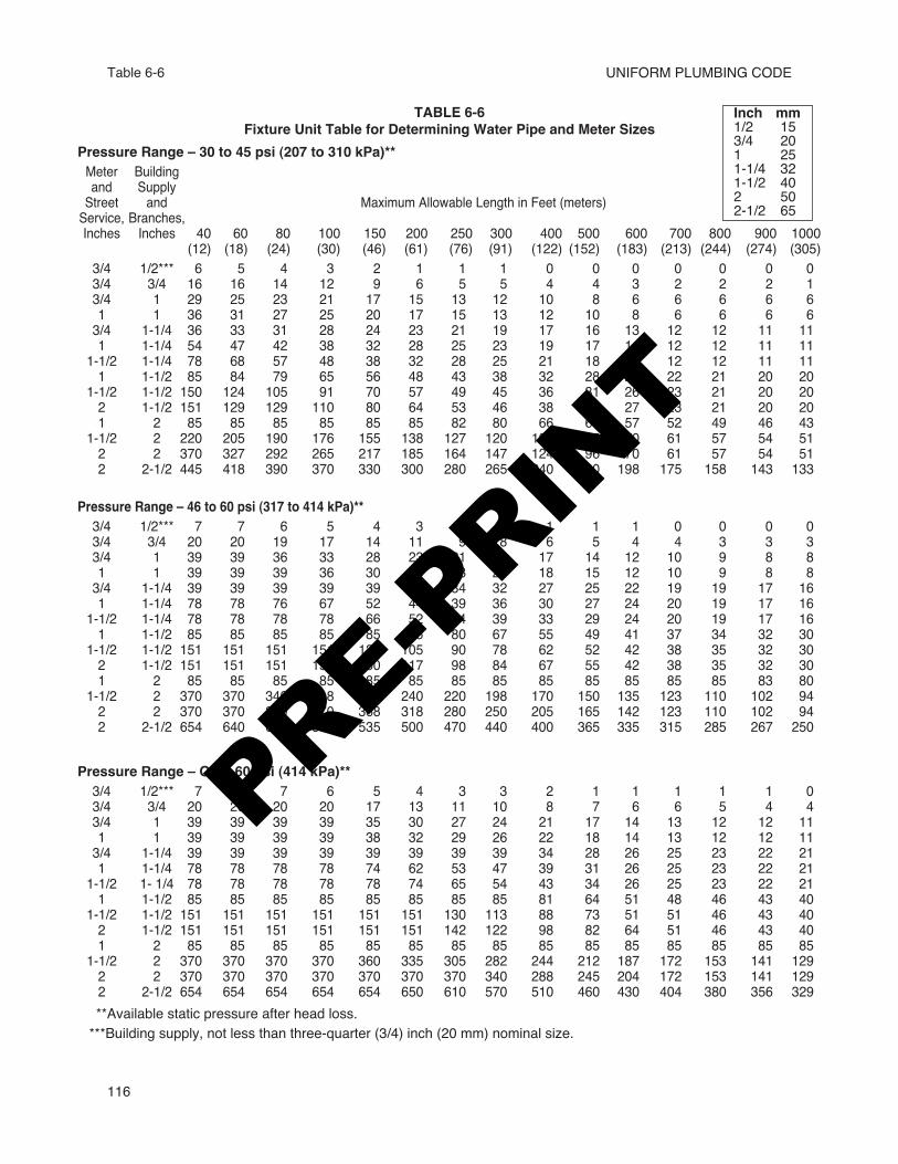
Table 6-6
TABLE 6-6Fixture Unit Table for Determining Water Pipe and Meter Sizes
Pressure Range – 30 to 45 psi (207 to 310 kPa)**Meter Buildingand SupplyStreet and Maximum Allowable Length in Feet (meters)Service, Branches,Inches Inches 40 60 80 100 150 200 250 300 400 500 600 700 800 900 1000
(12) (18) (24) (30) (46) (61) (76) (91) (122) (152) (183) (213) (244) (274) (305)3/4 1/2*** 6 5 4 3 2 1 1 1 0 0 0 0 0 0 03/4 3/4 16 16 14 12 9 6 5 5 4 4 3 2 2 2 13/4 1 29 25 23 21 17 15 13 12 10 8 6 6 6 6 61 1 36 31 27 25 20 17 15 13 12 10 8 6 6 6 63/4 1-1/4 36 33 31 28 24 23 21 19 17 16 13 12 12 11 111 1-1/4 54 47 42 38 32 28 25 23 19 17 14 12 12 11 11
1-1/2 1-1/4 78 68 57 48 38 32 28 25 21 18 15 12 12 11 111 1-1/2 85 84 79 65 56 48 43 38 32 28 26 22 21 20 20
1-1/2 1-1/2 150 124 105 91 70 57 49 45 36 31 26 23 21 20 202 1-1/2 151 129 129 110 80 64 53 46 38 32 27 23 21 20 201 2 85 85 85 85 85 85 82 80 66 61 57 52 49 46 43
1-1/2 2 220 205 190 176 155 138 127 120 104 85 70 61 57 54 512 2 370 327 292 265 217 185 164 147 124 96 70 61 57 54 512 2-1/2 445 418 390 370 330 300 280 265 240 220 198 175 158 143 133
Pressure Range – 46 to 60 psi (317 to 414 kPa)**3/4 1/2*** 7 7 6 5 4 3 2 2 1 1 1 0 0 0 03/4 3/4 20 20 19 17 14 11 9 8 6 5 4 4 3 3 33/4 1 39 39 36 33 28 23 21 19 17 14 12 10 9 8 81 1 39 39 39 36 30 25 23 20 18 15 12 10 9 8 83/4 1-1/4 39 39 39 39 39 39 34 32 27 25 22 19 19 17 161 1-1/4 78 78 76 67 52 44 39 36 30 27 24 20 19 17 16
1-1/2 1-1/4 78 78 78 78 66 52 44 39 33 29 24 20 19 17 161 1-1/2 85 85 85 85 85 85 80 67 55 49 41 37 34 32 30
1-1/2 1-1/2 151 151 151 151 128 105 90 78 62 52 42 38 35 32 302 1-1/2 151 151 151 151 150 117 98 84 67 55 42 38 35 32 301 2 85 85 85 85 85 85 85 85 85 85 85 85 85 83 80
1-1/2 2 370 370 340 318 272 240 220 198 170 150 135 123 110 102 942 2 370 370 370 370 368 318 280 250 205 165 142 123 110 102 942 2-1/2 654 640 610 580 535 500 470 440 400 365 335 315 285 267 250
Pressure Range – Over 60 psi (414 kPa)**3/4 1/2*** 7 7 7 6 5 4 3 3 2 1 1 1 1 1 03/4 3/4 20 20 20 20 17 13 11 10 8 7 6 6 5 4 43/4 1 39 39 39 39 35 30 27 24 21 17 14 13 12 12 111 1 39 39 39 39 38 32 29 26 22 18 14 13 12 12 113/4 1-1/4 39 39 39 39 39 39 39 39 34 28 26 25 23 22 211 1-1/4 78 78 78 78 74 62 53 47 39 31 26 25 23 22 21
1-1/2 1- 1/4 78 78 78 78 78 74 65 54 43 34 26 25 23 22 211 1-1/2 85 85 85 85 85 85 85 85 81 64 51 48 46 43 40
1-1/2 1-1/2 151 151 151 151 151 151 130 113 88 73 51 51 46 43 402 1-1/2 151 151 151 151 151 151 142 122 98 82 64 51 46 43 401 2 85 85 85 85 85 85 85 85 85 85 85 85 85 85 85
1-1/2 2 370 370 370 370 360 335 305 282 244 212 187 172 153 141 1292 2 370 370 370 370 370 370 370 340 288 245 204 172 153 141 1292 2-1/2 654 654 654 654 654 650 610 570 510 460 430 404 380 356 329**Available static pressure after head loss.***Building supply, not less than three-quarter (3/4) inch (20 mm) nominal size.
Inch mm1/2 153/4 201 251-1/4 321-1/2 402 502-1/2 65
PRE-PRIN
T
WATER SUPPLY AND DISTRIBUTION
117
Table 6-7 – Table 6-8
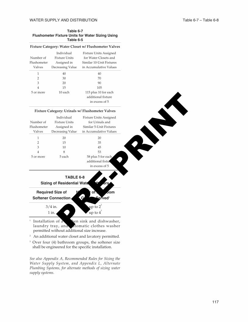
Table 6-7Flushometer Fixture Units for Water Sizing Using
Table 6-5Fixture Category: Water Closet w/ Flushometer Valves
Individual Fixture Units AssignedNumber of Fixture Units for Water Closets andFlushometer Assigned in Similar 10-Unit Fixtures
Valves Decreasing Value in Accumulative Values
1 40 402 30 703 20 904 15 105
5 or more 10 each 115 plus 10 for eachadditional fixture
in excess of 5
Fixture Category: Urinals w/ Flushometer Valves
Individual Fixture Units AssignedNumber of Fixture Units for Urinals andFlushometer Assigned in Similar 5-Unit Fixtures
Valves Decreasing Value in Accumulative Values
1 20 202 15 353 10 454 8 53
5 or more 5 each 58 plus 5 for eachadditional fixture
in excess of 5
TABLE 6-8Sizing of Residential Water Softeners
Required Size of Number of BathroomSoftener Connection Groups Served1
3/4 in. up to 22
1 in. up to 43
1 Installation of a kitchen sink and dishwasher,laundry tray, and automatic clothes washerpermitted without additional size increase.
2 An additional water closet and lavatory permitted.3 Over four (4) bathroom groups, the softener size
shall be engineered for the specific installation.
See also Appendix A, Recommended Rules for Sizing theWater Supply System, and Appendix L, AlternatePlumbing Systems, for alternate methods of sizing watersupply systems.
PRE-PRIN
T

UNIFORM PLUMBING CODE
118
PRE-PRIN
T