report on the short term scientific mission on combining
TRANSCRIPT

1
Report on the Short Term Scientific Mission on “Combining
Modeling Languages to Support Usability-Driven DSL Development
with USE-ME”
Dominique Blouin
LTCI Lab, Telecom ParisTech, Université Paris Saclay
46 rue Barrault, 75013, Paris, France
1 Initial Purpose of the Visit DSLs offer expressiveness to specify CPSs at the proper level of abstraction, before they are
automatically deployed or even simulated, with notations close to the end user domain. DSLs are
designed to bridge the gap between the problem domain (essential concepts, domain knowledge,
techniques, and paradigms) and the solution domain (technical space, middleware, platforms and
programming languages). Bridging this gap is expected to increase productivity. However, engineers
seem to underestimate the importance of aligning the languages, in particular their notations and
tools, with the skills of their end users [1]. Assessing the impact of introducing a DSL for CPS
development requires focusing on the productivity gains resulting from the extent to which the
domain users are able to use the languages with their notations and tools [2]. Investment into this
assessment, commonly called usability evaluation is justified by the resulting reduction of
development costs and increased revenues brought by improved effectiveness and efficiency of DSLs
end users.
The lack of systematic approaches, guidelines and comprehensive set of tools may explain DSLs
evaluations shortcomings in the current state of practice. This situation is due to the perceived high
costs of DSL evaluation, which lacks a consistent and computer-aided integration of two different
and demanding complementary software processes: DSL development and usability engineering. An
iterative approach is required to track the usability requirements, including the context of use of the
DSL in and its environment, as well as the impact of recommendations with well-prepared
evaluation processes. Such approach can be well supported by modeling all these aspects making
use of the most appropriate languages and tools. A first attempt of defining the required concepts
for such approach has been made through the specification of the Usability Software Engineering
Modeling Environment (USE-ME), a framework developed by Ankiça Barisic [3] at the NOVA
Laboratory for Computer Science and Informatics (NOVALINCS) at the university Nova of in Lisbon
which is the host of this STSM. It is therefore with with Ms Barisic that I have mostly been working
during this STSM.
In some of my former research work, I proposed a combination of existing modeling language
standards in support of Requirements Engineering (RE) best practices recommended by the
Requirements Engineering Management Handbook (REMH) [4]. While the REMH has been written
with the safety-critical systems domain in mind and in particular the avionics domain, a large

2
majority of its practices are generic enough to be applicable for the development of many other
types of systems. In addition, the fragment language RDAL that I developed was explicitly designed
to be reusable with other languages, including other Architecture Description Languages (ADL) not
necessarily targeting the safety-critical embedded systems domain. Furthermore, it turns out that
the concepts of the RDAL-REMH approach also share many similarities with the concepts of USE-ME.
Therefore, the purpose of this STSM was to study the feasibility of reusing the RDAL-REMH approach
initially targeting safety-critical systems for usability-driven development of DSLs by providing a
complete model-based RE framework onto which USE-ME could be based. This would allow USE-ME
DSL to benefit from the REMH well-established practices and also be an opportunity to evaluate the
planned reuse capability of RDAL-REMH for a very different domain. Furthermore, given a positive
outcome of the planned study, the combination of existing languages and tools to be developed
would constitute an interesting case study of languages composition contributing to the main
objective of WG 1, which develops a framework to relate / combine modeling languages and tools.
2 Accomplished Work This section presents in some details the work accomplished during the STSM mission. The initial
objective of the mission was to determine the feasibility of using RDAL-REMH in support of USE-ME.
In order to evaluate this objective, we first conducted a comparative study of the concepts provided
by both approaches. Given the relatively short time required for performing this study and its
positive outcome, sufficient time became available to develop a first version of an extension of
RDAL-REMH for USE-ME and to start testing the extension with the Visualino case study of USE-ME.
In the next sections, first the USE-ME and RDAL-REMH approaches are introduced. Next, the
comparative study of the approaches is presented, followed by the RDAL-REMH extension that was
developed. Finally, an insight is given on the yet incomplete modeling of the USE-ME Visualino case
study with the developed extension.
2.1 USE-ME USE-ME [5] promotes an iterative user-centered evaluation approach for DSLs. Usability evaluations
are expressed as regular expert evaluator activities, in the software language engineering process.
Usability engineering aims at increasing the awareness and acceptance of established usability
methods among software practitioners. Knowledge of the basic usability methods is expected to
enhance the ease of use and acceptability of a system for a particular class of users carrying out
specific tasks in a specific environment. It is claimed to affect the user's performance and
satisfaction. Further, the software engineering supports the systematic development and is
concerned with all aspects of software production. However, the USE-ME framework is not intended
to fully support a complete development cycle, but to be integrated with existing approaches which
support DSL development. For instance a requirements engineering process for which the objective
is to provide a view on usability over a complete set of requirement models.
2.2 RDAL-REMH In 2008, the US Federal Aviation Administration (FAA) commanded a study of state-of-the-art
approaches from the RE research and survey of the current industry practices [6]. The purpose was
to determine methods that enable successful management, integration, verification and validation

3
of requirements that may be developed by multiple entities. The results of such study lead to the 11
best practices of the Requirements Engineering Management Handbook (REMH) [4]. Such practices,
have been developed to support their piecemeal adoption with minimal disruption of organization’s
development processes thus favoring adoption by industry of results from the RE research.
Table 1 lists the 11 best practices with a short description for each of them. Despite that the REMH
was developed for the safety-critical embedded systems domain, it can be observed from the table
that a large majority of the practices are not specific to this domain and can potentially be beneficial
for other domains.
# Name Summary
1 Develop the System Overview
Provide a high level view of the system to be developed describing its purpose, how it interacts with its environment and why the system is needed.
2 Identify the System Boundary
Provides a sound understanding of what lies within the system to be built and what lies within the larger world. Define the exact interaction of the system with its environment through monitored and controlled variables.
3 Develop the Operational Concepts
Provide scenarios that describe how the system will be used and the context in which it will be used.
4 Identify the Environmental Assumptions
Identify the assumptions on which a system depends for correct operation. These can be specified as a mathematical relationship between the controlled and the monitored variables, or as the types, ranges, and units of the monitored and controlled variables.
5 Develop the Functional Architecture
Organize requirements into functions that are logically related with minimal dependencies between them to enhance readability and make them robust in face of change. Break down functions into smaller sub-functions for scalability for large systems.
6 Revise the Architecture to Meet Implementation Constraints
Revise the ideal functional architecture early to meet implementation constraints such as those related to safety or to the need to integrate with legacy systems. Start from the previously developed ideal functional architecture and iterate to develop an architecture that addresses these constraints. This architecture is then used for organizing the detailed requirements.
7 Identify System Modes
Modes define discontinuities in the system behavior that are visible from the operators or other systems. Break down the specification of the detailed requirements per identified modes.
8 Develop Detailed Behavior and Performance Requirements
Produce a complete and consistent set of detailed system requirements that define how the system must change the controlled variables in response to changes in the monitored variables. Specify the value of the controlled variable for each system state and inputs, the allowed tolerance of the values and performance characteristics such as the allowed latency.
9 Define Software Requirements
Define software requirements that map to the system requirements and their architecture as a straightforward extension of the system requirements.
10 Allocate System Requirements to
For large systems, allocate requirements to subsystems that can be developed independently by subcontractors, in a manner that is consistent with the other
4
Subsystems recommended practices.
11 Provide Rationale Provide rationale documentation on why each requirement or environmental assumption exists.
Table 1: Overview of the REMH best practices
In some of my former research work, I proposed a combination of existing modeling languages and
tools in support of these REMH practices. It involved the combination of the User Requirements
Notation (URN, ITU recommendation Z.155 standard) [7] to model use cases, the Architecture
Analysis and Design Language (AADL, SAE AS5506B standard) [8] for modeling safety-critical real-
time embedded systems architectures, and the Requirements Definition and Analysis Language
(RDAL) [9], a fragment language that I developed to model and analyze requirements combined with
other languages providing use case and system architecture modeling capabilities and integrated via
RDAL into a common framework. The jUCMNav tool [10] was used for the URN language and the
OSATE tool for AADL [11]. RDAL and the combination of these languages are provided by the RDAL
Tool Environment (RDALTE) [12].
This combination of languages was exercised for one of the example natural language requirements
specification provided by the REMH to illustrate its practices, and for a case study from the medical
domain consisting of a Patient Controlled Analgesia Pump [13]. The approach was shown to be very
beneficial as it allowed improving significantly the quality of the requirements and design
specifications [14].
While so far the fragment language RDAL has only been used with URN and AADL, it had been
explicitly designed to be reusable with other languages than AADL not necessarily targeting the
safety-critical embedded systems domain. Therefore, retargeting the approach for a totally different
domain such as DSL development was of great interest for me.
2.3 Comparative Study of RDAL-REMH and USE-ME Approaches To tackle the work of this STSM, we first studied the concepts of both the RDAL-REMH and USE-ME
approaches and compared them in order to evaluate the required effort and potential benefits of
extending RDAL-REMH to support USE-ME.
2.3.1 Overview
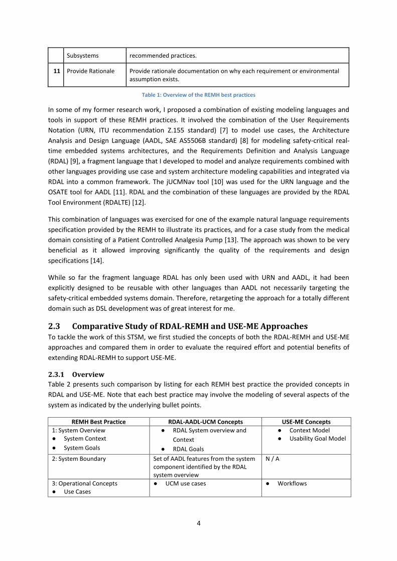
Table 2 presents such comparison by listing for each REMH best practice the provided concepts in
RDAL and USE-ME. Note that each best practice may involve the modeling of several aspects of the
system as indicated by the underlying bullet points.
REMH Best Practice RDAL-AADL-UCM Concepts USE-ME Concepts 1: System Overview ● System Context
● System Goals
● RDAL System overview and
Context
● RDAL Goals
● Context Model ● Usability Goal Model
2: System Boundary Set of AADL features from the system component identified by the RDAL system overview
N / A
3: Operational Concepts ● Use Cases
● UCM use cases ● Workflows

5
4: Environmental Assumptions ● External Entities
● Assumptions
● AADL components from the
environment identified from the
RDAL system overview
● RDAL Assumptions
● User Hierarchy ● Environment Context
(technical, physical and social environment)
5: Functional Architecture ● High Level Requirements
● RDAL top level of hierarchy
requirements
N / A
6: Architecture Revision to meet Implementation Constraints
● RDAL evolution traceability links N / A
7: System Modes ● AADL system operation modes ● Scope of usability goals
8: Detailed Behavior and Performance Requirements
● RDAL requirements refining the
top level requirements
● Only addresses usability performance requirements
9: Software Requirements ● RDAL refining specification
containing requirements refining
the system requirements
Not applicable
10: Subsystems Requirements Allocation
● RDAL / AADL refining
specifications
N / A, but could be considered later
11: Rationale ● RDAL Rationale construct ● Rational can be described through Method of Usability Goal
Table 2: A comparison of the RDAL and USE-ME concepts for supporting the REMH best practices
2.3.2 Discussion
It can be seen from the table that many concepts are also covered by USE-ME, but with a narrower focus on usability. In RDAL, usability has no specific focus and can only be identified by allocating preconfigured usability categories to various elements such as goals and requirements. RDAL indeed allows users to define hierarchical category systems in order to tag some of its elements. However, the modeling of all other RE elements will provide an essential base for the USE-ME viewpoint on usability.
As for use cases, it was observed that USE-ME could greatly benefit from the modeling of use cases using the Use Case Maps sub-language of the URN by allowing their simulation thus complementing the corresponding Workflow concept in USE-ME.
A strength of USE-ME is its usability goal coverage or achievement analysis supporting iterative development of the DSL. Similar approach was also developed for RDAL but in the context of optimizing the embedded systems quality attributes during design refinement model transformations [15].
A major lack that was found during comparative study however is the lack of an appropriate language for representing the architecture design aspect of a DSL in a similar fashion provided by AADL for embedded systems. Reusing AADL for modeling a DSL and its environment as it is done for embedded systems would not be appropriate due to the large difference between the domains. This triggered the development of a simple design language for the specification of DSL-based systems as introduced in the next section
It should also be noted that some parts of the RDAL-REMH approach are not relevant for DSL development. For example, the software requirements BP # 9 dealing with the translation of system requirements into software requirements taking into account the different representation of system variables in software do not need to be considered. Such software requirements do not exist for DSL development.
6
Overall, given this comparison, we concluded that many of the features provided by RDAL-REMH would be beneficial for USE-ME as it would avoid redeveloping these constructs. Furthermore, this would constitute an opportunity to use RDAL with a different architecture description language than AADL that is the DSL-based Systems Specification Language (DSSL) introduced in the next section.
2.4 The DSL-based Systems Specification Language (DSSL) As mentioned above, one outcome of the comparative study was that there was a need for an
architecture design language to specify the DSL that is being built as well as its environment, and to
be used in conjunction with RDAL and UCM. In RDAL-REMH, the AADL language was used for this
because so far because it only addressed the embedded systems domain. The DSL development
domain is of such different nature that we decided to create a simple DSL that we named the DSL-
based Systems Specification Language (DSSL). The purpose of such language is to model the design
of a DSL being developed and the way it is used in its environment. Stakeholder goals, requirements
and environmental assumptions can then be allocated to elements of this representation of the DSL
under development. Furthermore, DSSL allows integrating the real implementation of the developed
DSL as an Ecore meta-model potentially including graphical and / or textual concrete syntax
represented as Sirius / Xtext (or any other Ecore-based syntax specification) models.
2.4.1 Declarative Specification
The DSSL language provides means to specify the context of use of the developed DSL in its
environment. Because there are typically several contexts of use, the language needs to include
concepts to declare component types. Such types are then instantiated for each context instance
thus allowing reusing the declared type properties across various contexts of use of the DSL.
The DSSL declarative specification concepts are presented in Figure 1. A DSL-based system
specification element is used as a root container of all elements of a DSSL specification. Such
elements consists of various predefined context element types to be used in a context specification
for representing the developed DSL, its users, tools, workplaces, documentation and other
interacting physical systems (e.g. a robot). Tools can be further specialized into computers, and
software tools such as operating systems, model checkers, and simulators, etc.
2.4.2 Context Instance Specification
The purpose of the context instance specification concepts is to provide a means to specify the
various contexts of use of the developed DSL and its interaction with components of its
environment. This allows for modeling context diagrams promoted by the REMH through the system
overview development best practice (Table 1).
The DSSL context instance concepts are presented in Figure 2. A context specification captures a set
of context instance elements representing the various elements involved when the DSL under
development is used and how they interact with each other. Each instance element refers to an
element type from the declarative specification and thus inheriting its declared characteristics. Two
context instance elements can be connected to each other via an instance elements connection,
which relates a source feature of the class of the element type of a source instance element
component to a destination feature of the class of the element type of a destination instance
element.

7
Figure 1: A class diagram for the declarative elements of the DSSL language
2.4.3 DSL Specification
The purpose of the DSL specification concepts is to allow modeling the DSL under development and
its internal constituents such as its abstract and concrete syntaxes, its semantics, documentation and
optionally some feature diagrams that may have served in elaborating the DSL. The DSL-related
concepts are shown in Figure 3.
A DSL owns a set of domain concepts constituting the language vocabulary. Note that concrete
implementations for the DSL’s syntaxes and domain concepts need to be provided for these abstract
classes. The DSSL language provides such default implementations classes for the Ecore meta-meta-
model. Therefore, an Ecore domain concept links a DSSL domain concept to an Ecore class
implementing the concept in the form of an EClass. An Ecore abstract syntax links a DSSL abstract
syntax to a set of Ecore packages declaring the domain concepts of the language as a set of EClasses.
Finally, a Sirius concrete syntax links a DSSL concrete syntax to a Sirius diagram specification
contained in a group element of the Sirius language and providing the visual notation for the domain
concepts of the DSL.
Providing such concrete DSL implementation classes allows for allocating detailed low level
requirements to the actual concepts and associated concrete syntax elements and allows to verify its
concrete properties via associated OCL constraint statements.
2.5 The RDALTE USE-ME Extension The RDAL-REMH approach is supported by the Eclipse-EMF based RDAL Tool Environment (RDALTE)
[12]. It provides the RDAL language and its editors, as well and a settings model specifying how the

8
RDAL, UCM and design language (AADL or DSSL) languages can be combined [9]. Such model
provides rules for the types of the elements of the combined languages (UCM and AADL) that can be
associated with the built-in RDAL traceability features. Therefore, a new settings model had to be
provided targeting the new DSSL language.
Figure 2: A class diagram for the context instance elements of the DSSL language
Furthermore, the settings model allows for declaring user-defined hierarchical categories to be used
to tag various elements of RDAL (goals, requirements, assumptions, tests, etc.). Therefore, a
predefined set of categories was also created for the USE-ME case with a set dedicated on usability.
Finally, RDALTE makes use of a service Java class implementing a model interface for accessing the
elements of the combined models in an agnostic way. Therefore, a class specific to the new DSSL
language and to be instantiated by the tool at startup time had to be developed and specified in the
settings model.
2.6 Modeling the Visualino Case Study We used the Visualino language [16] as a case study to develop a prototype requirements
specification for this DSL. The case study was selected as it was already used to validate the USE-ME
framework. Visualino is a visual language that allows children to develop programs to control
Arduino robots through the manipulation of visual elements or objects. It avoids having to program

9
the Arduino textual code directly, which requires technical skills not owned by the vast majority of
children. Visualino specifications programmed by children are then automatically translated into the
Arduino textual code. This activity is expected to help the children to understand quickly
programming mechanisms. A strong engagement factor is that children have the opportunity to
observe their own developed program running on a physical robot. This way, they receive feedback
on the implications of slight changes in their program.
Figure 3: A class diagram for the DSL elements of the DSSL language
Visualino’s first prototype was developed as a joint project between Artica, a company that
specializes in the development of robotic and audio-visual solutions in Lisbon and the NOVA LINCS
research lab. During the Visualino development cycle, the exploratory evaluations were conducted
with the objective of assessing the usability of the visual syntax provided by the language, the
learnability of the associated tooling and users satisfaction, which is one of the primary
characteristics to be assessed during usability evaluations.
Unfortunately, the given one week duration of the STSM was too short to allow completing the
modeling of this use case. This is still ongoing work between the two institutions. However, we
provide as an appendix (section 6) an excerpt of the current requirements specification, which
follows the REMH best practices applicable to DSL development. The specification is provided in its

10
current state mostly expressed in natural language for now except for the use cases, which have
been modeled with jUCMnav the tool implementing URN. Note that the actual models can be found
on a Github project that was created for collaboration and made available at
https://github.com/akki55/useme.
3 Results of the STSM The main outcome of this STSM is that the RDAL-REMH approach can be extended for supporting
DSL development, which we started to implement during the visit. This takes the form of a meta-
model for the DSL-based Systems Specification Language (DSSL) and an extension of RDALTE for its
integration.
We believe that providing modeling support following the REMH best practices supported by RDAL
and the combined languages including the USE-ME view for DSL development will lead to significant
improvements of the overall DSL quality and especially its usability.
4 Future Collaborations with the Host Institution Following this STSM that took place during the week of January 16th at the University Nova of
Lisbon, we have been pursuing this collaboration by setting up a shared repository on Github at
https://github.com/akki55/useme.
4.1 Short Term Collaboration The very short term next step will consists of finishing the modeling of the Visualino case study. This
should help validate the applicability of the REMH practices to DSL development.
In a subsequent step, we will develop a mechanism to support the integration of USE-ME with RDAL-
REMH providing a view on usability on the complete requirements specifications. The mapping of
Table 2 will be used for that. We also plan to base this work on the framework to relate modeling
languages and tools currently being developed by the WG 1 of the MPM4CPS COST action that
funded this mission. One main element of this framework is the concept viewpoint relating
stakeholder concerns with parts of the system being built and the formalisms, languages and tools
being used for modeling and analyzing these concerns. We will consider the EMF Views tool [17] as a
first implementation prototype to implement USE-ME as a view on RDAL-REMH.
4.2 Longer Term Collaboration A longer term collaboration will consists of further evaluating the resulting framework with more
complex case studies and improve its ability to develop better DSL development beyond the usability
concern.
4.3 Foreseen Publications We plan to publish a conference paper about this work. However, we have not yet identified a
specific venue although the Software Language Engineering (SLE) or the MODELS conference would
be an adequate venue. This venue will be selected once we have made sufficient progress on this
ongoing work.

11
5 References 1. Völter, M., Dietrich, C., Engelmann, B., Helander, M., Kats, L., Visser, E., & Wachsmuth, DSL
Engineering: Designing, Implementing and Using Domain-Specific Languages, CreateSpace Independent Publishing Platform, 2013.
2. Barišić, A., Amaral, V., Goulão, M., Barroca, B., How to reach a usable DSL? Moving toward a systematic evaluation, Electronic Communications of the EASST: 5th Int. Workshop on Multi-Paradigm Modeling (MPM 2011), 50, 13.
3. Barišić, A., Usability evaluation of Domain-Specific Languages, PhD Thesis Plan Proposal, FCT Universidade Nova de Lisboa, Portugal, 2015.
4. Lempia, D., Miller, S., Requirements Engineering Management Handbook, Federal Aviation
Administration (FAA), Tech. Rep., 2009.
5. Barišić, Ankica, Usability Software Engineering - Modeling Environment (USE-ME 1.0), 2016, doi: 10.5281/ZENODO.189245, https://zenodo.org/record/189245#.WJCbV7aLTdQ
6. Lempia, D., Miller, S., Requirements Engineering Management Findings Report, Federal
Aviation Administration (FAA), Tech. Rep., 2009.
7. ITU URN Specification, http://www.itu.int/rec/T-REC-Z.150/en/.
8. SAE AADL Specification, http://standards.sae.org/as5506b/.
9. Blouin, D., Senn, E., Turki, S., Defining an annex language to the architecture analysis and
design language for requirements engineering activities support, First Model-Driven
Requirements Engineering Workshop (MoDRE), 2011.
10. The jUCMNav URN Tool Homepage, http://jucmnav.softwareengineering.ca/jucmnav/.
11. The Open Source AADL Tool Environtment, http://osate.org/.
12. The RDAL Tool Environment Homepage, https://wiki.sei.cmu.edu/aadl/index.php/RDALTE/.
13. U.S. Food and Drug Administration Infusion Pumps Improvement Initiative,
http://www.fda.gov/MedicalDevices/ProductsandMedicalProcedures/GeneralHospitalDevic
esandSupplies/InfusionPumps/ucm202501.htm
14. Blouin, D., Giese, H., Combining Requirements, Use Case Maps and AADL Models for Safety-
Critical Systems Design, 42nd Euromicro conference on Software Engineering and Advanced
Applications (SEAA), 2016.
15. Loniewski, G., Borde, E., Blouin, D., Insfran, E. Model-Driven Requirements Engineering for
Embedded Systems Development, 39th Euromicro Conference on Software Engineering and
Advanced Applications SEAA 2013.
16. Leonardo, P., Child Programming: An adequate Domain Specific Language for programming
specific robots, Master dissertation, FCT Universidade Nova de Lisboa, Portugal, 2013.
17. Bruneliere, H., Perez, J. G., Wimmer, M., Cabot, J. EMF Views: A View Mechanism for
Integrating Heterogeneous Models. In Conceptual Modeling - 34th International Conference,
ER 2015.
6 Partial Visualino Requirements Specification (Ongoing Work)
6.1 System Overview / System Boundary / Preliminary System Goals The system being specified is the DSL for programming robots, called Visualino. The DSL is meant to
introduce programming concepts to the children by using a visual syntax based on behavior tree
diagrams.
12
The purpose of Visualino is to enable the persons without programming experience, especially the
children, to program a behavior of low-cost robot.
1. System Context - The DSL interacts with the:
1. User Interface which provide a visual elements to program and configure a behavior
of robot
2. Robot by generating modeled behavior to Arduino board
2. System Goals
1. G1 The user should be provided with a concepts to model behaviors of robot
2. G2 The domain experts should be supported to create customized configurations
3. G3 The software engineers should be supported to create new language component
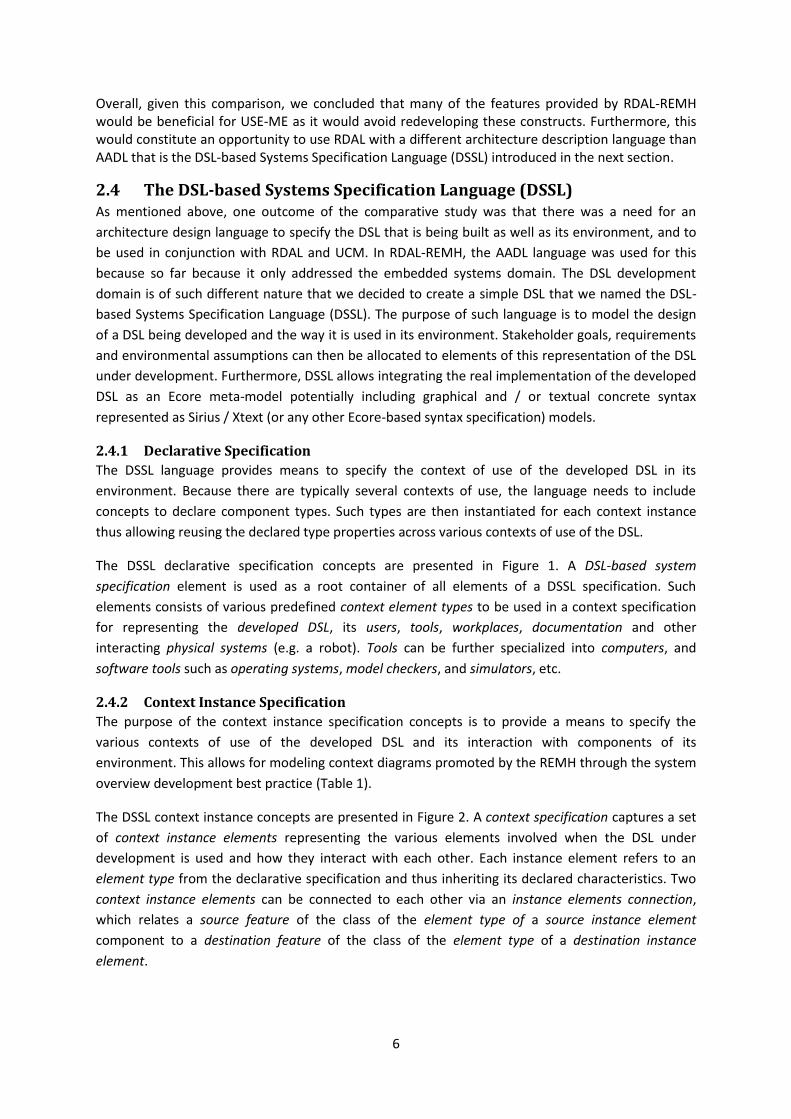
6.2 Use Cases A normal scenario (Figure 4) was considered to be the case where End User programs a behavior of
robot with having a robot to which the behavior can be executed. Alternative scenarios address a
case of programming a behavior of robot but without having actual robot provided.
Figure 4: Normal and alternative operating scenario
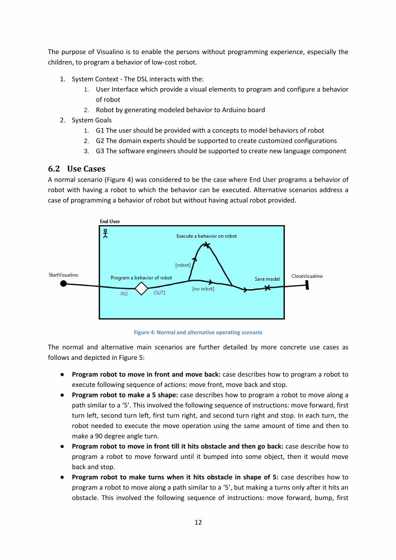
The normal and alternative main scenarios are further detailed by more concrete use cases as
follows and depicted in Figure 5:
● Program robot to move in front and move back: case describes how to program a robot to
execute following sequence of actions: move front, move back and stop.
● Program robot to make a 5 shape: case describes how to program a robot to move along a
path similar to a ‘5’. This involved the following sequence of instructions: move forward, first
turn left, second turn left, first turn right, and second turn right and stop. In each turn, the
robot needed to execute the move operation using the same amount of time and then to
make a 90 degree angle turn.
● Program robot to move in front till it hits obstacle and then go back: case describe how to
program a robot to move forward until it bumped into some object, then it would move
back and stop.
● Program robot to make turns when it hits obstacle in shape of 5: case describes how to
program a robot to move along a path similar to a ‘5’, but making a turns only after it hits an
obstacle. This involved the following sequence of instructions: move forward, bump, first
13
turn left, bump, second turn left, bump, first turn right, bump, and second turn right and
stop. In each turn, the robot needed to execute the move operation using the same amount
of time and then to make a 90 degree angle turn.
Figure 5: Program robot to move according to different sub scenarios
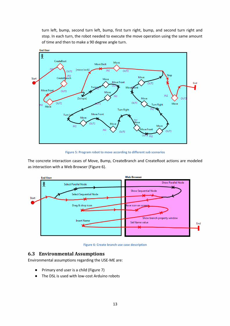
The concrete interaction cases of Move, Bump, CreateBranch and CreateRoot actions are modeled
as interaction with a Web Browser (Figure 6).
Figure 6: Create branch use case description
6.3 Environmental Assumptions Environmental assumptions regarding the USE-ME are:
● Primary end user is a child (Figure 7)
● The DSL is used with low-cost Arduino robots

14
Figure 7: User Hierarchy model for Visualino (taken from [5])
6.3.1 External Entities
The external entities are described by USE-Me framework as technical, physical and social
environmental elements (Figure 8).
Figure 8: Technical, physical and social environment description (taken from [5])
6.4 System Functions 1. Create a root - all the tree constructions for modelling a behavior start with a root. This is
where the hardware construction is made. All actuators and sensors that are connected to
the hardware are defined and configured here.
2. Sequence node - this node runs all child nodes sequentially, from left to right. Each node
runs and can end in success or failure. When a node ends with Success, the next node (from
left to right) runs. The sequence ends with a failure if one of the nodes fails, or ends in
success when all nodes have finished in success.
3. Parallel node- the parallel node runs all child nodes at the same time. This node can be
configured with different termination conditions. They may end in success or failure when all
child nodes succeed or fail, respectively.

15
4. Masking Result - sometimes it is necessary to change the normal termination result of a
node to create a behavior. With this node, we can directly change the state in the node
child, allowing you to create loops and various types of conditions.
5. Import Tree node - with this node, we can import a tree from another file and insert it as a
branch of the current tree.
6. Input node - input nodes read data from sensors attached to the system and may either
succeed or fail depending on the value of the sensor.
7. Outputs node - Output nodes are used to change the state of the actuators defined in the
root node.
8. Waiting node - Also called a delay, this node runs for a configurable period of time, and ends
in success.
9. Control Bar - at the top of the interface should be a bar where different tasks can be done:
● Opening and saving files
● Connect the interface to the hardware
● Send the tree to the hardware
● Write the tree to the hardware in permanent memory
● Erase the permanent memory tree
● Run the tree
● Stop running the tree
● Pause tree execution
● Move forward in stepper
10. Properties - whenever a node of the tree is selected, a panel configurable with the
properties of that node.
11. The logic - The behavior tree is read from top to bottom and from left to right.