report on the trans-alaska pipeline service tanker
TRANSCRIPT

THE SOCIETY OF NAVAL ARCHITECTS AND MARINE ENGINEERS601 Pavonla Avenue, Suite ‘~, Jersay City, New Jersey 07306 USA
Paper puaenti at the Mtitm SWUCUJtAInapadon, M#ntemanrn,and Monitoring SympsiumStwaton Naiional Hotel, Arlk@n, Wglnia, March i 519, 1931
Report on the Trans-Alaska Pipeline Service TankerStructural Failure StudyJ.D.Sipes,J.M. MacDonald,M.R. Bowen, H.P.Cojeen,B. Salerno,J.C. MaxhamandJ. Baxter,OfficeofMarineSafety,SecurityandEnvironmentalProtection,U.S.CoastGuard,Washington,DC
I .~1* -
A. tu al Ca9ualtv Studv The study” of tankess engaged in the TAPStraderis t;e culmi.natiion of ~elated initiatives dating back to April 1988.The first of these initiatives, the Structural Caaualty Study, dated April2“7, 1988, reported that TAPS tankers eompriaed 13 percent of U.S. flagoceangoing vessels over 10,000 gross tons between 1984 and 1988, butaccounted for 59 percent of the structural failures, i.e. , cracking in thehull plates and connecting structural members, that had been reported toCoast Guard Headquarters. That finding lead to the conclusion that TAPStankers suffered a disproportionately higher number of structural failureswhen compared to vessels in other trades...,.,
B. TAPS Studv Work Plan.. Following a significant fracture in the main
deck of the EXXON NORTH SLOPE on March 5, 1989, the investigation ofstructural”failures on TAPS--vesselswas formally undertaken byCommandant(G-MVI) and (G-MTH.). A Work Plan-was developed with thefollowing objectives:
(1) Development of short and long-term sclutions to structuralfailures;(2) Development cf Critical Areas Inspection Plans; and(3) Review of ABS rules and development of guidance and requirements.
C. The Tanker Accidental Oil OUTflow Studv Group. Following the groundingof the EXXON VALl)EZon March 24, 1989, in Prince William Sound, themembers of the TAPS Study Group were temporarily redirected to etherissues related to that grcunding. Rear. Admiral J. D. Sipes, Chieft Officeof Marine Safety, Security and Environmental Protection, assembled aworking group to review and assess issues related to tank vessels. Thisgroup, chaired by Captain J. C. Card (USCG), was called the TankerAccidental Oil Outflow Study Group. In its report titled
including, but not limited to:
(1) review of structural failures by trade;(2)elimination of tankers from c@rtaih waters;
(3) providing for mere Coast Guard inspections of tank vessels; and(4)dedication of more Coast Guard resources to the analysis ofcasualty and inspection data.
D. Tanker Safetv Studv Group. On October 6, 1989, a separate study group,.- chaired by Rear Admiral H. H. Bell (USCG R~t”.) igsued recommendations in itS
ReDort of the Tanker Safetv Studv GrouD related to tank vessels in general..’ and to TAPS tankers specifically.As a ~esult, the scope of the TAPS Study
was expanded to investigatematters related to inspection efficiency and themethods used to conduct inspections cf large tank vessels.
VI-A-I

2. Meetin~s With TAPS ODerato~s
In an effort to get infomnation from the operators of TAPS tankers, letterswere sent to the operators of TAPS vessels with documented structural failures.The letters advised the operators of our findings and requested one-on-onemeetings to discuss operating and maintenance philosophies, and programs theyuse to document and track structural failures. Meetings ,were,heldwith 14operators between January 16 and May 30, 1990.
3. ~terim Policv
Initialfindingsby the TAPS StudyGroupshowedthat the CoastGuard’sdatabasewas incomplete.In addition,inconsistentrepairproceduresandheightenedenvironmentalconcernscreatedaneed to changethe classificationand reportingcriteriafor structuralfailures.MVI PolicyLetterNo. 23-89,dated20 December1989,was issuedchangingthe classificationsand reportingcriteriafor structuralfailures. Emphasiswas placedon locatingClass1failures.The definitionfor a Class1 failurewas changed,and a “structuralfailure”was distinguishedfrom “structural damage” for reporting PurPos@s.
4. Gen”eralFindinm bv the TAPS Studv Groub. Findings by the TAPS StudyGroupwere based”onan evaluationof the data thatwas assimilatedfrom 200CoastGuardvesselfiles,informationcontainedin”theMarineSafetyInformation”Sys~em(MSIS),and data fromthe operators. In the assimilation,“this informationwas used to identify vessels with cracking histories and ~odetermine possible causes. Information in MSIS identified 69 U.S. and 7foreign flag tankvessels that had made at least 1 port call at Valdez since1984, were still in semice, and thus subject to this Study. Each operator wemet with recognized the need to properly address structural failures not onlybecause of the threat to vessel structural integrity, but also because ofheightened environmental concerns. The meetings validated the Coast Guard’sdata-showing that specific vessels and classes of vessels were performingworse than other vessels and vessel classes. The dperators also indicated aneed to change the way the Coast Guard documents and evaluates structuralfailures. Figure II-1 lists the U:S. flag vessels, their’respective class,and the operating company as,of 29 September 1989.. Each of the U.S. flagvessels were classed by ABS.
A.. Time of Year. Analysis indicated that significant and potentiallyserious failures can occur on TAPS vessels at ~ time of the”year. Ingeneral, the more harsh the environmentthe more serious theeven~, i.e., allfour Class 1 events were documented betweenOctober and March,,
B. VesselConstruction (materials”andconfimration); Analyses showed:
(1) vessels with cargo blocks constructedof a combination of mild and hightensile steel or solely of high tensile steel experienced disproportionatelyhigher numbers of structural failures than vessels built solely-ofmild steel;
(2) single .hull.vessels, regardless of the type of steel, comprised 62.3%of those studied and accounted f~r nearly 80% of the failure events; and
(.3)vessels built to full sc-antlings,“regardlessof type of steel, sufferedthe same proportion of failures as vessels built to reduced scantlings.”
.,.
VI-A-2

c. Vt+sselClass (desire). Data in MSIS showedthatthe 69 vesselssubjectto thisStudy comprised 28 separate vesselclasses(27 established classes andone special “Not In A Class”’catego’ky,set up only for this Study, for threevessels not ‘inan established class). The six vessels in the Atigun PassClass, whose entire cargo block section is constructed of high tensile steel,accounted for 26.3% of the failure events. -Five classes, comprising 23vessels, accounted for 66.9% of the documented failures. The vessel MOBILARCTIC (Not In A Class) accounted for 8 of the failure events, making a totalof 24 (34.8%)vessels accountingfor 72.9% ofthe documented”failureevents.The following vessels have been-identifiedas requiring special inspection,monitoring -and/orreportingmeasures:
(1) The Atirnm Pass class vessels have experienced the most frequentoccurrence of cracking, including two of the four documented Class 1 eventsreviewed by the TAPS ‘StudyGroup. These vessels are presently experiencingactive cracking foi which+effective detail retrofits have not been devised.
(2) The Seatrain Class vessel STUYVESANT experienced two Class 1 events,bothof which exceeded 17 feet in length in the main shell plating andresulted in significant pollution incidence. These incidence have beenattributed to.poor workmanship at the time of construction. It is our beliefthat the potentialexists for similar type cracking to recur on this vessel oroccur on the other vessels in this class.
(3) The American Sun Class vessels are experiencing active cracking forwhich repair solutions are being pursued. Much of the past cracking has beenattributed to poorinitial design and construction,,forwhich effective repairhave been made.
(4) ~“e MOBIL ARCTIC has had several Class 2 fractures in recent years,The vessel was builtwith numerous structural-deficienciesincludingmisalignments of supportmembers by as much as 3 inches, poor transitions,missing brackets, etc. Deficiencies have not become apparent until after afracture has occurred.
(5) The COVE’LEADER was not included with the original 69 vessels reviewedby the TAPS Study Group. It entered the TAPS trade in April, 1990, afterundergoing extensive structural repairs required by MO Portland, and requiresspecial attention due to-the vessel’s age andpast history.
(6) Although the vessels in the ARCO Anchora~e and Sansinena classesaccounted for a significant number of documented failures, measures have beentaken to analyze the failures and to develop long term permanent solutions forrepair. In most cases, the repairs have already been performed and theincidence of hull Gracking is considered to be under control. As a result,these-vessels require only special monitoring.
D. Ha ce of Build (construction and worlananshipl. Analyses showed thatfour shipyards built 40 (S7.9%) of the vessels under study, and that those40 vessels accounted for 86.5% of the failure events. Regardless of how welldesigned a vessel maybe, or how thoroughly-a detail is analyzed and engineeredfor a particular arrangement, poor welding technique or a poor weld willnegate the best of detail designs and possibly lead to a structural failure.
E. Desi&n of Details. The primary concern of most companies is the poor
VI-A-3

design of details, i.,e,the main,transverse anddiscontinuitiesexist..
the transitionpiecessuch aslongitudinalstrengthmembersA vesselwith poorly designed
brackets that connectwhere struc:tutaldetails will be subject
to a hi~h incidence of cracking regardless of environmental conditions. .
Analysi~ must not necessarily se a~med at increasing the strength (scantlings)of the vessel, but in reducing stress concentrations and in providing a betterload path for he stresses.
F. Corrosicm Control . Coating existence and maintenance significantlyaffects .vessel ,strucCural performance and qafe~y, particularly as tankersage. Proper surface preparation is the key to maximizing the se~ice life oftank coatings, which normally last from 7 to 15 years, depending upon whetherzinc or an epoxy-based coatings are used.
G. ~ ● &ulysis. indicates thatsorne.vessalsneed morefrequent internal i;pecti~ns than presently required. Several operatorsindicated that our drydock internal inspections may be improved by attendingABS ‘close-up” or pre-drydock internal sumeys frequently done.by them.Suneys are usu@y done by either rafting tanks, or by climbing the internalframework,Althoughraftingis not an absolutelysafemethoddue to problarnswith tankcleanli-nessand relatedpersonalhygieneconcerns,aqd with shipmotionand fluidsurgein the tank,it is generallyacceptedas the best,andmost costeffective,methodfor suneying the enc~retank.,
5. General Conclusions
A. Actions bv Vessel Omerators. A wide-variety’of maintenance andphilosophical views were expressed by the TAPS operators.Many operatorstakea proactiverole in addressingfracturesas theyoccur,with analysesbeingperfo~ed, and.:in discussing/collaborating with opera-torsof similar-classvessels. ‘Hanyoperators already have.progrsms which are the essence ofcritical areas inspection plans.
B. Cause”of Structural Failures. Poorly designed details, poor weldworlananship,and fatigue appear to be the major causes of structural failures,especially in association with ‘theuse of high tensile steel. Corrosion isalso one of theprimary types of structural degradation that can lead tostructural failures. When employed and strictly maintained, coatingmaintenance can be an effective way to slow corrosion and, hence, stresscorrosion cracking. There is no clear, single failure mechanism, and each andevery structural failure must be evaluated on a case-by-case basis.
c. ~“ture Acr ions. The variety of views and vessel performance, taken inconcert with limited Coast Guard resources.,necessitates that we target ourattention on specific operators and.specific vessels that require the mostattention and oversight. We must limit -impactupon-available Coast Guardresources and rely on the responsibilitiesentrusted in the operators andclassificationsocieties. Many policy changes thatwe are requesting shouldbe developed jointly with ABS and indust~, Coast Guard participation inJoint Industry Projpcts-(JIPs),along with close association of ABS, is anexcellent vehicle for addressing and resolving many of the issues raised inthis”report. One such JIP already begun is the University,of Californiaproject titled “StructuralMaintenance for New and Existing Ships”.
,...
WA-4

II. ~NTRODUGTION
\ r,A. MarineStructuralCasualtv Study..A 27’April 1988reportby the
MarineStructuralCasualtyStudyand a followup reportdated19 July 1989byG-MTHhighlightedcankahipsengagedin the TAPS trade. The resultsof thesestudiesindicatedthat:
(l).Between1984and.1988,TAPS tankerscomprised13 percentofU.S.flagoceangoingvesselsover 10;000grosstons,and
(2) the TAPS tankersaccountedfor 59 percentof the structuralfailures, i.e., cracking in the hull plates and connecting structuralmembers,.that,had been reported to Coast Guard Headquarters.
B. TAPS Studv Work Plan. Following a significant fracture in the maindeck of the EIXON NORTH SIQPE on March 5, 1989, the investigation ofstructural failures specifically on TAPS vessels was formally undertaken byCommandant (G-lfVI)and (G-MTH). A Work Plan was developed with the followingobjectives:
(1) Development of short-term and long-term solutions to structuralfailures. to be proposed by the TAPS operators and submitted for review andapproval-by
(2)closely the
Coast Gu~~~
the he;ican B&eau of Shipping (ABS) and the Coast Guard;
Development of Critical Areas Inspection Plans to monitor moreknown problem areas of the TAPS vessels; and
Review of ABS rules and development of joint industry, ABS andguidance and requirements.
c. ~eetin~ With Industrv and ABS. TAPS operators and ABS were notifiedby letter dated March 21, 1989, requesting a joint meeting at ABS WorldHeadquarters in Paramus, New Jersey, on May 23, 1989. Despite a redirectionof attention following the grounding of the EXXON VALDEZ on March 24, 1989, andthus a delay in TAPS study, the joint meeting was held. At that meeting, thefindings of the 27 April 1988 study were presented for discussion. Additionalinformationwas needed before the Coast Guard could detenninelwhether specialinspection policy was needed for vessels engaged in the TAPS trade.
The TAPS Study was formally undertaken on August 1, 1989, to review the CoastGuard files of TAPS tankers in an effort to collate all documented structuralfailures, both reported and unreported. The intent was to establish anhistorical database that would provide an indication of the extent of thefailures, whether there were any common causes, and what actions could be takento mitigate future failures. Follow up action could then be taken with ABSand the operators of those vessels noted as being prone to structural failures.
Only those structural failures that had occurred since 1984 on vessels callingon the Port of Valdez were reviewed. Failures that had occurred within thelast five years were the only ones considered since they likely to be activerepair areas with repair procedures either still under analysis or beingmonitored.
Initially, 69 U.S. and 7 foreign flagidentified as TAPS vessels subject to
tank vessels still in semice werereview by the TAPS Study Group. Figure
VI-A-5

II-1liststhevessels,theirrespectiveclass:,and the operatingcompany at
the time this information was develope~. Those vessels act5vely trading inthe TAPS route as of the date of this report.are marked by an asterisk. TheHarine Safe~ Offices in-Portland, OR, Long Beach, CA, and Honolulu, HI, werevisited between 23 and 30 August 1989. All’information on file at those portsrelated to structural failures was reviewed, including 200 Coast Guard drydockexam recor&, independent sumeyor reports, CG-2752’S (Reports of StructuralFailure) and dsmage suneys. This information established the raw data uponwhich our analyses were conducted.
One-on-one meetings were held between January 16 andliay 30, 1990, with 14companies who had operated, or were operating, the vessels with documentedstructural failures. The purpose of these meetings was to discuss ourfindings and to solicit company background information on their TAPS vessels,their philosophies regarding the maintenance and operation of their vessels,and programs they have established to document and track structural failuresas well as what they have done to prevent or minimize their occurence. Theinformation obtained”from these meetings has been used to confirm the identityof those vessels that are actively engaged in the TAPS trade and to developactive repair areas for each vessel.
,.:.
VI-A-6

Figure II-1
CLASS
America Sun
ARCO Anchorage
Atigun Pass
Chevron GT
Dynachem
‘% - Exxon Baltimore
Exxon Charleston
Exxon Gettysburg...
Exxon Houston
Exxon San Francisco
Exxon Valdez
Golden Gate
b Jolla
Massachussettes
VESSEL
AMERICAN TWER*GLACIER BAY*ADMIRALTY BAY*ASPEN*
ARCO ANCHOWGE*ARCO JUNEAU*ARCO FAIRBANKS*OVERSEAS JUNEAU*
ATIGUN PASS*KEYSTONE CANYON*BROOKS RANGE*THOMPSON PASS*EXXON NORTH SLOPE*EXXON BENICIA*
CHEVRON OREGON*CHEVRON WASHINGTONCHEVRON LOUISIANA*-CHEVRONARIZONA
OMI HUDSON
EXXON
EXXON
EXXON
EXXON
EXXONEXXONEXXON
EXXONEXXON
BOSTON
CHARLESTON
JAMESTOWN
NEW ORLEANS*
SAN FMNCISCO*BATON ROUGE*PHILADELPHIA*
VALDEZ~NG BEACH*
GOLDEN GATE
CHESAPEAKE TWER
POTOMAC TRADER
OCEAN WIZARD
ARCO SPIRIT*ARCO INDEPENDENCE*
OPERATOR
American Trading
Trinidad Corp.Trinidad Corp.Trinidad Corp.
Transportation Co.
ARCO Marine, inc.ARCO Marine, Inc.ARGO Marine, Inc.Maritime Overseas Corp.
Keystone ShippingKeystone ShippingInterocean ManagementInterocean ManagementExxon ShippingExxon Shipping
Chevron ShippingChevron ShippingChevron ShippingChevron Shipping
OMI Corp.
Exxon Shipping
Exxon Shipping
Exxon Shipping
Exxon Shipping
Exxon ShippingExxon ShippingExxon Shipping
Exxon ShippingExxon Shipping
Keystone Shipping
American Trading Transportation Co.American Trading Transportation Co.
Boston Ocean CarriersARCO Marine, Inc.ARCO Marine, Inc.
“*Vessel is actively engaged in TAPS trade as of date of this report
VI-A-7

Figure II-1 (Cent’d)
OPERATORCoastal Tankers
Q?MsMontrachet
-COASTAL MANTEE USA, Inc.
PETERSBURGPetersburg
Liberty Maritime Corp.Maritime Overseas Corp.Maritime Overseas Corp.
Marine Transport LinesMarine Transport LinesARCO Marine, Inc.ARCO Marine, Inc.
West Coast ShippingARGO Marine, Inc.ARCO Marine, Inc.Chevron ShippingChevron Shipping
San Clemente LIBERTY BELLEOVERSEAS NEW YORKOVERSEAS WASHINGTON
San Diego B. T. SAN DIEGO*B. T. ALASKAARco AIASKA*ARCO CALIFORNIA*
Sansinena SANSINENA II*ARCO PRUDHOE BAY*ARCO SAG RIVER*CHEVRON CALIFOWIA*CHEVRON MISSISSIPPI*
Santa Paula Sabine Towing & TransportCo.SABINE
Sealift
Seatrain
SEALIFT PACIFIC Marine Transport Lines
Texaco Marinehid-UpBay TankersBay Tankers
BROOKLYNWILLIAMSBURGH**STUYVESANTBAY RIDGE
/
Sunship TAPS PRINCE WILLIAM SOUND*TONSINA*KENAI*
Sun TransportKeystone ShippingKeystone Shipping
Texaco New York
Western Sun
Reflagged
TEXACO CONNECTICUTTEXACO FLORIDA
Texaco MarineTexaco Marine
Mobil Oil Corp.
Cove ShippingOMI Corp.Cambridge Tankers, Inc.
American Trading TransportationCover Trader, Inc.Mobil Oil ’Corp.American Trading Transportation
“Mobil Oil Corp.ARCO Marine, Inc.Exxon Shipping
SYOSSET
COVE LIBERTYOMI COLUMBIAOVERSEA BOSTON
20-Year Old BALTIMORE TMDERCOVE TIWNIRMOBIL MERIDIANPENNSYLVANIA TRADER
Not In A Class 140BILARCTIC*ARCO TEXAS*EXXON BAYTOWN
* Vessel “isactively.engaged in TAPS “tradeas of date of this report** Vessel listed for Class identification only
...,,- not engaged in TAPS trade
VI-A-8

\ 1.
The
III. FINDINGS BY THE TAPS STUDY GROUP
ovemiew of the TAPS Study
TAPS Tanker Structural Failure Study comprised two phases.
A. Phase-I covered the period from 21 March 1989 to 15 January 1990 andincluded the following actions:
(1) Ajoint meeting with TAPS operators andABS on May 23, 1989, atABS World headquarters in Paramus, New Jersey.
(2) Review of all Coast Guard files of tank ships having called on theport of Valdez since 1984 and development of structural failure historydatabases from the reports of structural failures contained therein.
(3) Evaluation of the structural failure databases to determine whichvessels were experiencing the most numbers of failures and why.-
(4) The establishment of new, interim policy via G-MVI Policy Letter23-89, dated 20 December 1989, changing the definitions of structural failuresand the reporting criteria-for same.
(5) Notification of the operators of TAPS vessels apprising them of“the preliminary findings and scheduling one-on-one meetings with them.
B. Phase II of the TAPS study covered the period from 16 January to 31May 1990 and included one-on-one meetings with TAPS operators between 16January and 30 May 1990 to
(l)-presentthe preliminary findings of the TAPS Study group;-
(2) discuss the changes that the Coast Guard had made in itsinspection policies for the inspection of large tank ships; and
(3) solicit information from the operators that would supplement thedatabases developed during Phase I and either corroborate andexplain, or refute the preliminary findings of the TAPS Study.
2. Sunected Causes of Struct ral Fu ailures
The structural failure histories dqveloped during Phase I of the TAPS Studywere evaluated to determine whether possible causes for structural failurescould be related to one or a combination of
(1)
(2)
(3)
(4)
“’theincreased use of high tensile steels in the cargo block, eitherfully con&tructed with high tensile steel or in combination with mildsteel;
the reduction of scantlfngs based upon the use of protective coatingsin tanks;
lighter scantlings due to the use of high tensile steels;
poorweld worlunanship, including fabrication and fit-up, during the
VI-A-9

(5)
(6)
construction of the vessel, resulting in stress risers in butt andseam welds;
poor design of details, resulting in hard spots and extreme stressrisers; and
exposure to an extremely harsh environmental’climate in the.G@f ofAlaska
3. )!eetiruzsWith TAPS ODerators
During Phase II, meetings were held with the 14 companies listed below:
.
.
.
.
.
-..
These
Exxon Shipping Company 17 January 1990Chevron Shipping Company 18 January 1990ARCO Marine, Inc. 24 January 1990West Coast Shipping Company 26 January199,0Sun Marketing and Refining, Inc. 30 January 1990 .,Texaco Marine Services, Inc. 01 February 1990Keystone,Shipping Company 13’February 1990Interoce,an Management Corporation 15 Febmary 1~90
Mobil Oil Corporation 20 February 1990
Trinidad Corporation 27 February 1990
Ma~icime Overseas Corporation 28 F:biuary 1990.
Amekican Trading and Transportation 16 March 1990
Cove Shipping Company 11 May 1990”
Marine Transport Lines , 30 May1990 .
meetings provided valuable insight into operating and:rnaintenancephilosophies,which varied considerably between companies, and into thereasons why the structural failures were occuring.. The information obtainedfrom the operators”wasused to enhance our data analyses and to assess thecorrelationsbetween failures and causes listed in paragraph 2 above. Theinformationprovided by the operators indicated that some of the preliminaryfindings of the TAPS Study group should be adjusted to take into account otherfactors and information that was either nat available or not apparent from theraw data contain+d in the initial structural failure databases.
4. Vessels Reaulrin~ SDecial Inspection and”RePortinQ Measures
,.Figure III-1 shows that the 69 vessels subject”to this”Study comprised”28separate,vesselclasses (27 established classes and one special “Not In AClass” category, set up only for th”isStudy, for three TAPS vessels notin anestablished class). Of those 28 classes, the Atigun,Pass..Class,consisting.of6 vessels whose entire cargo block section was constructed of high tensilesteel, alone accounted for 26.3% of the documented structural failure events.Five classes, comprising 23 vessels, accounted for 66.9% of the.documentedfailures. In addition, the vessel MO.BILARCTIC (Not In A Class) accounted for8 of the failure events, making a total of 24 (34.8%) vessels accounting for72.9% of the.documented failure events. Therefore, as aresult of ouranalyses and informationprovided by the operating companies, the followingvessels were identified as requiring special inspection, monitoring and/orreporting measures, as indicated: .!
.
.
.,.., -
VI-A-1o

FIGURXIII-1
-.zgxu!
u.!
VI-A-I 1

.. .
/i. Atimn Pass ClassSe-ice: Crude Carrier
Vessel DWT uATIGUN PASS ~73380 1977KEYSTONE CANYON 173619 1978BROOKS RANGE 176102 1978THOMPSON PASS 173320 1978EXXON N. SLOPE 175305 1979EXXON BENICIA 172573 1979
SIEELHi-SeHi-StHi-StHi-StHi-StHi-St
SCANTLINGSREDUCED?NONONONONONO
DOUBLESIDES?
NONONONONONO
DOUBLEBOTTOM?
NO
NONONONONO
The vessels.in the Atigun Pass class have experienced the most frequentoccurence of cracking,‘including 2 of the 4 documented Class-l events reviewedby the TAPS Stpdy Group. These vessels arepresently experiencing activecracking for which effective detail retrofits have no”t treen devised. -Thisclass theiefoi,e: requires specfal attentidn’with regard to inspection, themonitoring of repairs and follow-up action, and the reporting’”of structuralfailures.. Thd~first four vessels in this Class have experienced” cracking inthe areas listed below. These areas have been identified as .accive repairareas, i.e.,-repairs have either been made,,.andare being .monitore.d,or areundergoing analysis for a long term permanent fix that will involve a redesignof certain details.
~~ATIGUN PASS, KEYSTONE CANYON, BROOKS RANGE & THOMPSON PASS:
Bilge Keelsflin way of the toe “ofthe keel plate;,.
Side shell.longitudinalsadjacent to bulkheads 421 52 and 58;
Bottom longitudinal limber holes; and
Frame 29,-No. 1 port and starboaxd wing tanks.. The underdeck forward offrame “29was strengthenedby Keystone andInkeroceanManagementfollowing weather damage: This”could have moved stress aft into Frame29, causing the cracks.
The KEYSTONE CANYON, BROOKS ~GE &THOMPSON PASS have experienced fewer“..
fractures than ATIGUN PASS due to some structural members installedduring initial construction that were.not installed on che ATIGUN PASS..
Initial aEtempts to solve cracks .inside Iongitudinals near bracketedends tha.tthen propagated into side -shellinvolved,the installation of“inertia bars”. Subsequent analysisand experiencehasshown that theinertia bars did not correct the problem. Bracketkhave sincebeenadded over several yardperiods per the reco~endation of the OilCompany International Marine Forum (OCIMF) tanker book Guide to theInspection and-Condition Assessment of Tankers.
In February 1990, the BROOKS RANGE experienced two fractures in the No.3 center cargo tank - 1 in the base metal adjacent CP the transverseerectiotibytt joint at frame.52 near the center vertical keeli and theother outboard of the first crack in the we”lderection joint in way of alongitudinal limber hole.
The THOMPSON PASS has had numerous side shell fractures in the xl
VI-A-I 2

starboard cargo tank, the most recent being an 8“ crack in January,1990. In July, 1989, 3 individual fractures totaling 17 feet in leng~happeared along the toe of a transverse field-erectionweld in the bottomplating of #3 center cargo tank.
EXXON BENICIA & NORTH SLOPE: These .twovessels have a raised forecastle(the other four are flush deck) and have fewer documented structural failuresthan the other ves”selsin this Class.
The EXXON BENIGIA has had problems with cracking of”the underdecklongitudinal at frames 64 - 65, attributed to poor design details andfabrication defects. These Iongitudinalswere originally flat bar withface plates added to provide additional support for bollards and otherdeck equipment. In some locations, the added face plates terminated“shortof connecting brackets at ‘transversebulkheads, resulting instress concentrationswhich in turn lendto cracking. Analysis has shownthat the size of brackets could be increased to spread out stresses andfix the cracking problem on some of the longitudinal; however, this fixhas no effect on other longitudinal. Repairs/mods have been effectedby installing new, larger brackets, but since the analysis did notprovide conclusive information for all the repair areas, they are beingmonitored. Subsequent analysis shows that fatigue life has not beenimproved for all fixes; thus-additionalmodifications are planned,including removal of face plates and brackets where consideredunnecessary and, where larger stiffeners are required, deeper and/orthicker slab longitudinal will be used.
The other Atigun Pass vessels have not had the same problem with poorflat barfiracket design. Exxon may be experiencingmore underdeck‘cracking.because the number of possible problem locations is increaseddue to underdeck “strengthening”on the two Exxon ships,
These vessels had early cracking in the flange of cargo tank sluice gatevalves in way of the corner bolt hole. This problem has apparently beencorrected by modifying the flange to remove the bolt hole and inserting
the flange with DH (high streng~h) steel.
B. Seatrain ClassService: Crude Carrier
Vessel D~~
BROOKLYN 2~80WILLIAMSBURGH 228701STUYVESANT 228274BAY RIDGE 224428
YE4RBUILT -1973” Mild1974 Mild1977 Mild1979 Mild
experiencedthefeet in length.
SCANTLINGS DOUBLE DOUBLEREDUCED? SIDES? BOTTOM?Yes No NoYes No NoYes No NoYes No No
other 2 documented Class 1 events,‘Each of these cracks, one in the
The vessel STUYVESANT hasboth of which exceeded 17bottom shell plating between frames 55 and 56 in the No. 5 Port cargo tank, theother in the side shell plating of the No. 5 starboard cargo tank, resulted inthe spillage of more than 100,000 gallons of crude oil. Since the potentialexists for s“imilartype cracking to occur on the other vessels in this class,the Seatrain Class requires attention similar to that for the Atigun Pass.Class. Other significant fractures tinthe STUYVESANT include the following:
VI-A-13
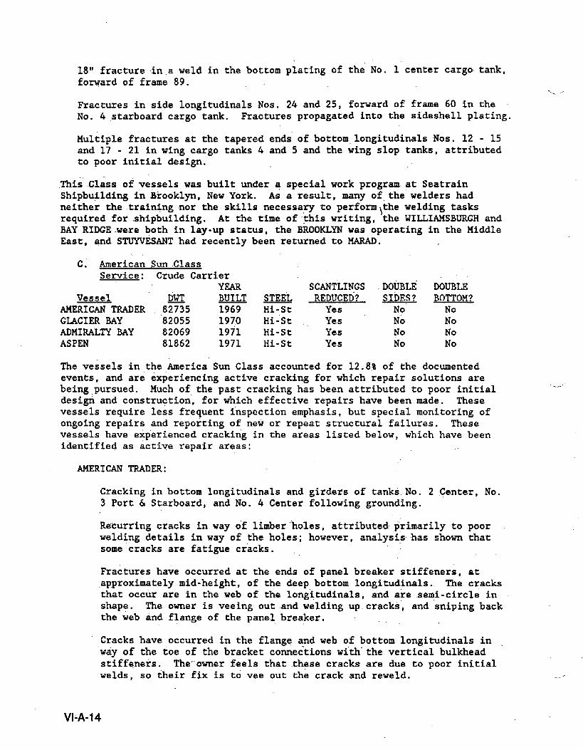
18” fracture in.a weld in the bottom plating of the No. 1 center cargo tank,foward of frame 89. ,. \._,.
Fractures in side longitudinal Nos. 24 and 25, forward of frame 60 in theNo. 4.starboard cargo tank. Fractures propagated into the sideshell plating.
Multiple fractures at the tapered ends of bottomlongi.tudinalsNos. 12 - 15and 17 - 21 in wing cargo tanks 4 and 5 and the wing slop tanks, attributedto poor initial design.
This Class of vessels was built under q special work program. at SeatrainShipbuilding in.Biooklyn, New York. As a result, many of the welders hadneither the training nor the skills necessary to performlthe welding tasksrequired for shipbuilding. At the time of~his writing, theWI~IAMSBURGH andBAY RIDGE .we.reboth in lay-up status, theBROOKLYNwas operatingin the MiddleEast,and STUYVESANThad recentlybeen returnedto MA.RAD.
C. .AmericanSun .ClassServtce: Crude Carrier.
YEAR SCANTLINGS .DOUB~” DOUBLEVessel ‘“ ~ BUILT STEEL REDUCED? SIDES? BOTTOM?
AMERICfi T~ER 82735 1969 Hi-St Yes No NoGT.ACIERBAY “82055 1970 H%:St . Yes No No
ADMIRhL~ BAY 82069 1971 Hi-St Yes No NoASPEN 81862 1971 Hi-St Yes No No
The vessels in the America Sun Class accounted for 12.8% of the documentedevents, and are experiencing active cracking for which repair solutions arebeing,pursued. Much of the past cracking has been attributed to poor initialdesign and construction, for which effective repairs have been made. Thesevessels require less frequent inspection emphasis, but special monitoring ofongoing repairs and reporting of new or repeat structural failures. Thesevessels have experienced cracking in the areas listed below, which have beenidentified as active repair areas:
AMERICAN TR3DER:
Cracking in bottom longitudinal and girders of tanks No.3 Port & Starboard, and No. 4 Center following grounding.
2 .Center,No.
R@eurring cracks in way of limber’holes, attributed primarily to poorwelding details in way of the holes; however, analysis has shown thatsome“cracksare fatigue cr”acks.
Fractures have occurred at the ends of panel breaker stiffeners, at,ap,proximatelymid-height, of the deep bottom longitudinal.. The cracksthat occur are in the web of the longitudinal, and are semi-circle inshape. The owner is veeing out and welding up.cracks, and sniping backthe web and.flange of the panel breaker.
Cracks have occurred in the flange and web of bottom.longitudinals in .‘way of the toe of the bracket connections with-the verti=l bulkheadstiffeners. The’”ownerfee”lsthat these cracks are due,to poor initialwelds, so their fix is to vee out the crack and “reweld. -.,-
WA-14

ADMIRALTY BAY,GIACIERBAY & ASPEN:
Fracturesin bottomlongitud~nals26i 27, 29 and 30 in No. 3 port andStarboardwing tanksat thebracketattachmentto transversegirdersandframes. Basedupon the resultsof an ABS study,riderbars and webinsertsof DH36 steeland reconfiguredbrackets, are being installedin2s,3s and4s.
Crackingof h~rizontalstiffenerendingson web of longitudinalgirderat web framesand bulkheads.Toe padshad been fittedearlierbutdidn’twork. Horizontalbracketshave sincebeen addedto make thestructurelongitudinallycontinuous(asopposedto snipingback thebracketas performedon the AMERICANTRADER).
D. Vessels Not In A Clas~
~: Crude CarrierSCANTLINGS DOUBLE DOUBLE
Ves$el m BUILT m REDUCED? SIDES? BOTTOM?MOBIL ARCTIC 124999 1972 Hi-St No No No
The vessel MOBIL ARCTIC, not in a class, has had several Class 2 fractures inrecent years. The vessel was built with numerous structural deficienciesincludh:rnisalimments of support members by-as much as 3“, poor transitions,missing’brackets,etc. Deficiencies didfracture occurred. This vessel requiresAtigun Pass Class vessels.
E. Vessels In the 20-Year Old ClassSemite: Crude Carrie;
YEAR
not-become apparent until after aattention similar to that for the
SCANTLINGS DOUBLE DOUBLEVessel m BUILT STEEL REDUCED? SIDES? BOTTOM?
COVELEM3ER 73034 1959 Mild No No No,-
The vesselCOVE LEADER, which was not included with the original 69 vesselsreviewed by the TAPS Study Group, entered the TAPS trade in April, 1990. Thevessel was required by MSO Portland to undergo extensive structural repairsprior to going into TAPS sewice. Due to the vessel’s age and past history,this vessel requires attention similar to that for the Atigun Pass Classvessels and MOBIL ARCTIC,
F. Vessels To Be Monitored. Although the two classes of vessels listedbelow accounted for a significant number of documented failures, measures havebeen taken”by the operating companies to analyze the failures and to developlong term permanent solutions for repair. In most cases, the repairs havealready been performed. As a result, these vessels require only specialmonitoring of the specified areas.
Class: ARCO AnchorageSemite: Crude Carrier
Vessel m uARCO ANCHORAGE 122249 1973ARCO JUNEAU 122249 1974ARCO FAIRBANKS 122520 1974OVERSEAS JUNEAU 122410 1973
SzEELMildMildMildMild
SCANTLINGSREDUCED?NoNoNoNo
DOUBLESIDES?NoNoNoNo
DOUBLE
lQlZQM2NoNoNoNo
VI-A-15

ARCO ANCHORAGE, JUNEAU & FAIRBANKS:
Cracking oritransverse bulkheaib in.cutouts in way of throughlomgitudinals. This ismost pronounced in-wing ballast ”tanks. Repairs ‘...,..
made wieh soft bracket.
The JUNEAU struck a bridge several years ago, requiring exte~iverepairs and.renewal of steel. There are concerns that locked instresses,createdduring repair of this damage may.make their presenceknown within the next couple of years.
ARCO FAIRBANKS:-
Fractures of side longitudinal 19 & 20 were repaired in 1987. Thesefractures were suspected as being caused by wave slap in the vicinity ofthe waterline, and are therefore not considered active repairs.
OVERS~SJUNEAU: No documentedstructuralfailures.
Class: SansinenaService: Crude Carrier
YEAR SCANTLINGS”-DOUBLE DOUBLE,Vessel & BUILT STEEL REDUCED? SIDES? BOTTOM?SANSINENA II 71589 1971 Hi-St ~No” -, No P-85‘ARCO PRUDHOE BAY 70738 1971 Hi-St No No P-85ARCO SAG RIVER 70215 1972 Hi-St No .,No P-85CHEVRON CALIFORNIA 71339 1972 Hi-St No No P-85CHEVRON MISSISSIPPI 70213 1972 Hi-St No No P-85
SANSIN,RNA II:
Fractures in web portion of transverse web frames in’way of web lapjoint and snipe in flange butt. Common in ballast tanks near bothbottom shell and main deck. Cracks appear to start near face plate andtravel towardsshell. Appears to be.result of fatigue and poor design.Lap (joggle joint) replacedby an insert plate as cracks-appear. Also,since web face plate is in a transition from 6“,to 12”’..inthis area, theface plate’is renewed to relocate butt/snipe location and to smoothwidth transition.
Fractures:in side longitudinal at toe of bracket,to transverse webframe. This occurs one web frame aft of the transverse,bulkheads at theswinger plate levels. Here the side.longicvdinalsstop..one frame aftof the bulkhead and arebracketed off to the web frame. Cracks occurredin..theweb and flange of the side longitudinal. It,appears that thebrackets that existed were too abrupt. Softer bracke~s were.installed.
Cracks and buckles in brackets between transversebulkhead centerlinestiffeners and the CVK. A suitable repair may be to,just replace peroriginal since these are generally associated with long term degradation,Analysis has shown slight overstress,in the structure. Fix will improveload path by new bracket shapes that account for better transitionbetween differing bulkhead and bo~tom structural configurations.
...
VI-A-1 6

Fractures in vertical bulkhead stiffeners in way of cut-out near lapconnection to bottom longitudinal. Bracket has been added to stiffenthe intersection.
This vessel has not had problems with fractures in the side longitudinalin way of the transverse web fr~es that CHEVRON CALIFORNIA and CHEVRONMISSISSIPPI have experienced. During detail plan review, the owner madesure that lugs were placed in way of the cut-outs in the web frame forthe side longitudinal (there were none on the Chevron ships).
ARCO PRUDHOE BAY & ARCO SAG RIVER:
longitudinal crack at bulkhead of ballast tank and stiffener.
CHEVRON CALIFORNIA and CHEVRON HISSISSIPPI:
Side shell cracks and side longitudinal cracks. (See illustration onpage 63 of ‘Guidance Manual for the Inspection and Condition Assessmentof Tanker Structures.”) This is the result of poor detailing. Ingeneral it occurred in way of lorigitudinals in way of cross struts ofthe transverse web frames. Squence of ’failure: (1) crack in flat barconnection CO stiffener; (2) crack in free edge of cut OUC; (3) crack inside shell; and (4) crack in radius openings of the cut-outs. Solutionwas to add bracket to back-up flat bar and provide lug in way oflongitudinal.
Cracks in erection joint near frame 55. Cracks are the result ofgeneral corrosion. Erection joint rewelded.
5. Findinm Re~ardinz“the Causes”of Structural Failures.
A. Hikh Tensile Steel (HTS)
There was a general consensus among the TAPS operators that modern vessels,built within the last 20 years, which contain HTS have more problems than theolder vessels constructed solely of mild steel. Of particular note are thevessels in the Atigun Pass class, whose entire cargo block section consists ofHTS. Some operators were quite vocal in their disdain for higher strengthsteels. Some felt that HTS has no place on large vessels because thetechnology employed in actual design and construction of these ships is notadequate to produce HTS vessels tha~ will not have cracking problems.
A majority of the naval architects and structural engineers who attended themeetings in company with TAPS operators felt that HTS was the source of many ofthe cracking problems, but that the cause of these cracks was not from theinnate properties of the steel itself. They felt that structural failures onvessels with HTS could be attributed to poor or inadequate design of detailsand workmanship, which contributes to an increased incidence of fatiguefailure. The major concern with details is that thqosethat are being used onhigh tensile steel vessels are the same as those that have been usedtraditionally on smaller, mild steel vessels without corresponding analysis totake into account the fatigue concerns associated with the higher allowablestress associated with higher strength steels.,.
VI-A-17

B. Reduced Scantlin~sfllnimalDesiRn
Figure 111-2 shows that
(l) -vessels whosecargoblocksection,isconstrvcted~feithera combinationof mild andHTSs,orsolelyof HTS experienceddisproportionatelyhighernumbersof structuralfailuresthanvessels“builtonlyof mild steel;
(2) single hull-vessels, regardless of.the .type.of.steel, comprised 62.3% ofthose studied and accounted for nearly 80% of the structural failure events; and
(3) The number of vessels built with full scantlings, regardless of typeofsteel, suffered the same proportion of ,failuresas vessels built to reducedscantlings.
None of the companies provided information indicating that they believed thatreduced .scantlingswere a problem. In our analysis, we came to the sameconclusion,with,one exception. The vessels in the Atigun Pass class,,besideshaving 100% HTS in the cargo block,were also built to reducedScantlings.Anotherfeature.of thesevesselsthatmay contribute.to theirhigh incidenceofstructuralfailuresis thattheyhave transverseframespacingof 16’-10”,whichis .consider.ablylargerthanthe frame,spacingtypicallyfound”onsimilarsizetankvess”el.s..
c. Poor Weld Workmanship/Fabrication/Fit-Uo
Figure III-3 “showsthat the first four shipyards listed below built 40 (57.9%)of the vessels under study, and that those 40 vessels accounted for 86.5% ofthe failure events. The chart, in addition to the number of TAPS vessels built
,.
and the respective number o.fstructural failure events, shows the ratio offailures per TAPS vesselbuil”t.
,.’
ShinvardSeatrain>----Sunsh~p jAvondale.‘Bethlehem .Natiotial,Steel”Newport NewsFMC CorpMaryland ShipQuincyToddHiroshimaTamano
# of vessels & (%~3 ( 4.3)9 (13.0)12 (17.4)16 (23.2) ,11 (15.9)
7 (lo.i)4 ( 5.8)3(4.3)”1 (1.4)”1 ( 1.4)1 ( 1.4)1 ( 1.4) !
# of failures’& (%)12 ( 9.0) .,33 (24.8).40(30;1) :;30 (22.6)7 ( 5.3.)5 ( 3,8) ‘3 ( 2.3),2 ( 1.5) .“1 ( Ok)0(.--)0“(:.)
0,(--)
Ratio4.03.73:31.90,60.70,80.7 ““.1.00.00.00.0
Many structural failures were attributed to either poor welding in and ofitself -“undercutwelds, lack of penetration, wrong amperage.,.etc. - or to ‘poor design which did not provide sufficient room for a welder to physicallyposition himself to properly perform a good weld. There were other-instanceswhere an,improper-.rootgap, component misalignment and/or poqr edgepreparacitm, such -asa jagged edge caused by flame “trimming,before weldingcaused problems. In other cases, brackets and other components were eithernot installed or not completely welded. Regardless of how well designed a
VI-A-18

FIGURE III-2
■
,.
E’IA
?J
E=i‘;
““lI
IL
I
1“1’1I
t==k Ln
0
STu
u!5g’co
!58
H
VI-A-19

FIGURE III-3
..,_
Imnm
I
I
b-,, _l,,
“..
I t 1I Ill II I I1,
k!m0
.
.
,.
VI-A-20
vessel may be, or how thoroughly a detail is analyzed and engineered for aparticular arrangement, poor welding technique or,a poor weld will negate thebest of detail designs and possibly’lead to a structural failure. Further,with respect to missing details and poox worlananshipand despite the presenceof Coast Guard, classification society and shipyard personnel, there isinsufficientmanpower and time to conduct a thorough inspection of all weldsand structural details to ensure.that the vessel has been fully constructed tothe approved plans.
D. Design of Details
Practically every operator attributed most structural failures to poor designof structural details and poqr weld-workmanship, including fabrication andfit-up. The biggest problem with detail de.s.iignstems from the early designsin the late 60s and early 70s when tank vessels started to be designed usingsophisticated analytical techniques that lead to very efficient, optimizedstructures. .Inmany ways, these efficiencies brought about great advances inthe ship building and operat@g .industriesand facilitated the extreme growthin tanker size, However, the general effects of structural optimizationbrought about,a general.lighteningof scantlings, and problems with structuraldetails have resulted.
,Manyof the structural details used in larger vessels have been designed fromhistorical experience and fabrication preferences, and without any specificanalyses “requirementsor guidance contained in classification society rules.It was the general consensusamong the operators that studies have shown thatdetails that had ’provensatisfactory f~r older vintage mild steel constructionare not necessarily satisfactory.for newer vessel designs, particularly thosewith HTSS. Some structural details on these larger vessels have proven to beinadequate and subject to failure,
One common.detail that has been subject to failure on older vessels is lapjoints.. Fractures in lap joints are common in the transverse web structuresin wing tanks, In general, operators are repairing fractured lap joints withbutt-welded joints whenever possible,
Several of the.operators attributed many fractures to metal fatigue. “However,as one operator astutely noted, the word “Fatigue” doesn’t identify the causeof a problem - it simply means chata structure has a lower safety margin;therefore, proper terminology should -referto cracks due to lower safetyfaccors.rather than fatigue. The assessment of fatigue life is extremelycomplicated and requires evaluation of environmental conditions combined withcargo and ballast loading and distribution.
Some operators have spent, and continue to spend, considerable resources toanalyze details and have been successful in producing effective modificationand repair solutions. Several operators-supported the philosophy that carefulscrutiny of structural details contained in the vessel during the designstages must be,made to avoid structural problems after a vessel is built. Theoccurrence of fatigue damage on TApS vessels, however, will continue to be aproblem due .to the inability of structural designers to remove all stressconcentrations. -Manystructural components on ships have, and will continueto have, fatigue lives of only several years. Although considerable concernhas been voiced concerning the amount of flexing that larger tank vessels
VI-A-21

undergo in a seaway, particularly those that are built with high tensilesteels, there is ‘nothingwrong with a yessel flexing in a seaway,”provided thevessel has been properly designed to flex,‘justas an airplane is so designed.
,.
E. Environmental climate in the Gulf of Alaska
FigureIII-4 shows that the overall reporting and’documental-ionof structuralfailure events was evenly spread throughout the year, with a slightly hi”ghernumber of events documented between October and December (thirty-six,or27.1%); however, in the overall view, just a fraction more than half(sixty-seven,or 50..4%)of all events were documented during.the months fromOctober through March, the period when the most severe sea conditions would beexpected. Oui analysis did show that themor& harsh the ‘environment,‘ingeneral,the more serious the event. All four Class 1 events were documentedduring’the months from October through March; including‘twoin January.
-,. ,,,
Some opetiatorsstated that the TAPS-trade betwe’enthe west coast and the Gulfof Alaska is extremely harsh on vessels, while others claimed’that the routebetween the Gulf of Alaska and Korea and other far eastern’countries wasworse. The TAPS trade is highlighted due to-the concent~ation of large ”’sliipsbuilt.with HTSS currently trading out of Valdez. Also, the se& conditionsmost damaging to a vessel’s hull may not necessarily be the most severe seaconditions that c“anexist. Depending upon a vessel’s structure, loading, andcourse constraints mandated by its tra’ding”pattern(and Ghus ‘directionofseas)-,sea.conditions that are less than the most extreme can actually producemore severe racking forces on a vessel’s hul~. Although numerous’compani’essubscribe to weather routing services,‘we:athe”r‘routingdoes’not appear to be afeasible rnethodfor avoiding severe weather in the Gulf of Alaska due to therestricted trackline vessels must follow in transiting to and from Valdez. ,.,
The American Bureau of Shipping has conducted studies of wave data comparisonsbetween two TAPS routes and a North Atlantic route. In a report titledEnhanced Concerns’OverMarine Poliution, datedFebruary, 1990, ABS discussedcomparisons of wave data for the California to Alaska route, the Alaska toYokohama route, and the New York’to Roteerdam route. A mostpr’obable extremewave height of approximately 33 feet, based upon data fok the North Atlantic,was chosen as a norm for the comparison. While the wave severity for the NewYork.to Rotterdam route nearly matched”the norm of 33 feet, the wave”severityfor the-Alaska toYokohama route’was approximately 39feet, and that for theCalifornia to Alaska route approximately-40 feet. This data supports the viewthat the environmental climate’-inthe GuI’fof Alaska can”be considered more ofa problem for tankers on the TAPSroute than those in North Atlantic se”nice.Ships inthe North Altantic service”alsohave more routing options to avoidstorms, whereas vessels in the TAPS trade”donot. ,,
Some operators felt that the TAPS trade is merely coincidental to crackingproblems.and.that cracking problems are nonspecific to TAPS vessels. Thisgroup of operators felt that, since most fai’luresare attributed to poorlydesigned detailsand/or poor welding, the natural working of a vessel’s hullin-any seaway will eventually result in a “fatiguefailurb. “The continuouslyharsh sea conditions found in the Gulf of.Alaska only exacerbates failures.Many felt that,.vesselsthat operate in international-trades,extensively intropical regions, experience structural failures th”atare also relateddirectly:to design of details.
‘.-. ...
VI-A-22

FIGURE III-4
a<Lu>
J
,,
I
Imill 1
IfjI
o
9
0
o

F. Ballasting Considerationsand Tank Bulkhead Flexing
Most operators have institutedheavy weather ballast procedures, some morespecific than others, whereby minimum amounts of additional (dirty) ballast is
-.—.
to be taken on in order to keep the vessel’s hull down and reduce the amountof pounding it would otherwise be exposed to. At the same time, manyoperators”acknowledged that ballast guidance is general, usually specifyingonly minimum amounts, and that the master has the discretion on how muchballast to take on. Masters even within the same company have differentpreferences and do not ballast in a uniform manner. One operator indicatedthat thereisa-need to overcome the mind setthat minimuu.,ballastis goodfrom an operations point of view and instill the knowledge that more ballastis better for ,thevessel.
Bulkheads bemeen cargo and ballast tanks undergo considerably more flexingthan bulkheads between cargo zanks due to”the reversal of forces? and thusstresses, between ballasted and loaded’ voyages. The flexing actionaccelerates the breakdown of tank coatings,’ and adds’ to” cor~osion rate alreadyexperienced in ballast tanks from the “salt water environment”.
., ,,
Further discussions regarding the operating philosophies of the companies,including ballasting procedures; corrosion control practices and instructionsto the master, are contained in the following seccion. --
.)”
,,.
....
VI-A-24
.._,.

IV. PHILOSOPHY OF THE TAPS 0PER4TORS ON VESSEL OPERATION AND MAINTENANCE
The philosophies of the various TAPS operators regarding the operation andmaintenance of their vessels vary considerably. Many companies indicatedeither verbally or in writing that they have some type of program in effectfor conducting internal exams and for locating and tracking structuralfailures. . While most of the programs have some degree of merit, some programswere judged to be far superior to others. “One general problem operators arefaced with is that reorganizations in recent years have frequently resulted inthe domkizing,of engineering and maintenance support staffs. Also, in someoperating companies, because of smaller engineering staffs, it may beimpractical to expect them to be able to cope with the administrative andtechnical requirements that are.needed to effectively implement programs toreduce the.”i”ncidencesof structural failures. The following discussionssummarize“thevarious operating and maintenance philosophies and highlight thebest programs es.tabl.ishedto deal with structural failures.
1. Tank Internal Sunevs
A. Freauencv of Survevs.
The frequency of internal exams of cargo and ballast tanks which operators,establishis generally set by the operators’ knowledge of their vessels’particular structural performance in conjunction with ABS surveys and CoastGuard required drydockings. Programs range from spot checks of ballast tanksafter each voyage, to general suneys of all ‘tanksonce a year, to completeinternal exams every six months (before and after”winter). Many operatorsalso conduct”internal,sumeys of ballast tanks and, to a lesser extent, ofcargo tanks 3 to 6 months prior to a vessel’s scheduled drydock exam in orderto find and document problem areas before the shipyard period rather than becaught short after the vessel enters the yard. These operators invariablystated that the cost of repairing cracks found after a ship is already in dockis considerably higher than those listed on a bid specification.
Other.operators hold to the philosophy that the proper place to find cracks isin the shipyard, and therefore do not conduct pre-shipyard surveys. Theybelieve that their yearly suweys will uncover any problems and that, sincethey correct the problems at the time they are found, an additionalpre-shipyard suwey will accomplish little. They also feel that there iseconomicincentive for shipyards to find cracks and, as a result, if a crackexist, the.shipyard will find.it..
The most aggressive program in effect involved a complete internal exam ofevery tank by raft ,evev”6 months, both before winter and again after. A fewoperators had no program in effect other than conductingrequired by the Coast Guard or ABS, or when repairs wererequired tanks to be cleaned.and gas freed.
B. Scope of Internal SuNevs..!
The scope of internal su~eys of”car~o and ballast tanks
surveys only whenconducted that
varies widely amongthe operators.’tanks, as thosethe duplication
Some operators .condu~tcomplete sumeys only in the ballasttaiiksundergo the most severe corrosion and wastage. Due coof design details tliroughout all tanks on a vessel, other
VI-A-25

opera~cwsinspect only a representative tank since a thorough inspection ofdetails in one tank w“illprovide a good indication of the condition of othertanks.
C. llkthods.UsedTO Conduct Internal Suweys....—..
Nearly every company agreed that conducting internal suneys on large tankersis a difficult undertaking. The most difficult areas to,inspect on largetankers are the upper areas and tinderdecksttucture of the cargo tanks. Onecompany clearly’“expressedthis ‘bystati’ngthe opinion that finding cracks onlarge vessels takes a combination of ,goodlighting, cornPetent~nsPectors ‘ho.know what to look for and where to look, and good luck.” ,
To conduct internal examinations,nearly all of’the companitii’use vesselcrews, port engineers and/or contract suneyors who are .f@niliarwith theirveisels; Using the same individuals is more productive ‘as,theyknow where thbproblems areas are and are more apt to”find them. In general, the personnelof the company or contractor who performed the inspections have 20 to 30 yearsof experience in performing structural inspections.
The use of rafts was generally acknowledgedby most companies as the best andmost cost effective method for conducting up close surveys of the upper levelsof a tank. Despite these apparent advantages, however, several companies donot use rafts to inspect tanks. They,be~ieve that it “isan inherentlydangerous method due to the sloshing of the water, even with the v~ssel atancho”rl In addition, there are conflicting considerations that must be madewith’regard to tank entry procedures and the.safety of P?r.sonnel. The raftingof tanks conducted outside of a shipyard are usually done without the benefitof a marine chemist to certify tanks safe for entry, particularly with regardto benzene exposure limits. One company also stated that tanks”must be dry ..-.and clean before conducting an inspection; otherwise,“crackswill not be foundunless the.crew.or inspector”knowsexactly where to.look”.
Some companies selectively stage certain tanks if there are knokn problemareas or when required for an ABS close up survey; A unanimous opinion wasthatcomp.lete staging of all tanks during a drydo!k is both COSt and timeprohibitive. ~5timates to stage 100% of tanks”ranged”frorn”,$250thousand to.“unthinkable”. In addition, few, if any, shipyards would’haye;enough stagingon hand to erect staging in every tank of a large tanker.
The Chief,” Office of Marine Inspection, Security and Enviro~ental Protectionis sponsoring and Research and”Development Progr~ in FY 1992 to” identify amore effective and efficient method by which to conduct tank examinations ontankships. me Project will involve the development of a device to be used byinspectors that will be small enough .to fit through a manhole, suitable foruse in an explosive atmosphere, and the ability”to display remotely” on a videoscreen.
,.
D. Personnel Safetv and Freauenc~ of Tank Instiections~ ‘
Several companies commented that the strict requirements forbenzsne:havesignificantly increased the time neede,dto clean and gas:fr~e Cargo tanks.Trinidad stated that it normally”’”takes7 days to clean dnd gas”freean entirevessel, and requires taking the vessel out of se~ice. Ballast tanks are alsodifficult to clean and gas free as they frequently have rnud”’inthe bottom that x.../
VI-A-26

must either be removed completely or at least stirred up to release anyentrapped gases.
2. Trackina Structural Failures/CriticalAreas lIISDeCtiOII Plan (CAIP)
Methods used-to documientand track structural failures range from sophicatedcomputer programs.to none. For the most part, critical areas inspection plansconsist.of the knowledge contained in the heads of the people who regularlyconductinternal surveys for the operators. The front line used by severalcompanies is thevessel’s crew. Other operators rely heavily upon in-housepersonnel and profe~sional surveyors under long term contract to inspect thesame vessels. The operators justified their “people” me”thodson the groundsthat these individuals are familiar with the vessels and know where theproblems are. There appeared to be no effort by some operators to documentstructural failures for long term evaluation for signs of patterning orrepeating. Other operators have taken, or have begun to take, active andagressive approaches to tracking structural cracking and developing writtencritical areas inspection plans.
Two operators have recently developed sophisticated computer programs.Although the primary intended use for”these programs is for budgeting andmaintenance purposes, they are capable of storing repair, gauging andmodification histories in minute detail for each Vessel. They can function asa critical areas-inspectionplan and capture structural failure profiles. Onthe other extreme, some Companies who did not have a viable program in effectfor tracking and resolving structural failures instituted new programs as aresult of the Commandant’s letters of December 1989, and our subsequent
/’ meetings with them. A few companies admitted that ttieyhad had to start from-..scratch to put together historical records and develop profiles for theirvessels. These companies.complementedthe Coast Guard for providing theincentivefor them.to do.this as they-all agreed that effective progras fortracking and resolving structural failures is good management and businesspractice.
Another operator is developing special condition and repair specificationsuney reports to be used in conjunction with a computer database.Developmentof the program slowed during recent months due to shifts incorporate needs to address other matters pertaining to tank vessel safety thatcame about as a result of the EXXON VALDEZ oil spill. This program is stillIn draft stages; however, they are in the process of contracting out thesoftwared eve-lopment. In conjunction wirh. the special sumey reports, thisoperator .is also developing a program that is intended to produce (1) athorough survey of all ships upon which to genetate a “critical area”inspection plan, (2) an in-house manual for inspection and approved repairs,and (3) a -computer program that will provide access to their database.
One operator places a great deal of emphasis on its shipboard managementprogram. -Masters-andchief engineers are.company employees, as are the otherlicensed officers, and are made responsible for the maintenance and repair oftheir vessels. This extends to shipyard periods where the crew is responsiblefor the quality control of work performedon their vessels. As an aid to thevessel’s crew in carrying out maintenance responsibilities, the operator hasprovided a shipboard computer system to track ’preventative maintenance: The
b system was desigfied prima.rily”by shipboard personnel. Under this program,
VI-A-27

every item on the ship is identified as a separate ‘system”.. Individual cargotanks, for example, are items in the “cargo system”. Regular maintenance isperformed on the elements in each syst~m so that the overall work load isspread out over time. Crew stability is very important to this scheme.
Companies that diydock their vessels overseas, particularly in Korea andJapan, have realized an added benefit not provided by U.S. shipyards.Followings drydocking period in an overseas.shipyard, the shipyard facilityprovides a report that extensively details all repairs that .weremade to thevessel, including.,detaileddrawings that depict all fractures.found, theirlocation,.si~e, and h~w repaired. These .reporcsare used to.establiih adatabase for the structural profiles of the vessels, and to identify repeatproblem areas for development of critical areas inspection plans.
3. Ereferred”Methods For Re~air
A. Evaluati~.. ,.
Again, philosophies regarding the repair of structural cracks, corrosion andpits varied widely.. Generally speaking, a majority of the operators, ..following discovery of a fracture, look at the surrounding areas, past history(isolated incident or repeat problem),and..thenext yard availability before,decidingupon a course of action. Normally, immediate repair is effected oncracks in critical areas, but cracks in non-criticalareas, often referred toas “nuisance cracks”# can be left alone with either minimal temporary repairor nb repair at” all.
—
B. Corrosio’~ and Pittin~.
A few operators” felt that nobody has a handle onit occurs, while others indicated that aback-upcoatings to:p,reventcorrosion cells from forming
-.
k...>.
pitting and the reason(s) whymethod is-needed for tankwhen the epoxy chips away.
Corrosion control procedures are futher discussed in section IV.7 below.
c. ReDair of Cracks.
The method generally used to repair cracksvaries by ope.ra.tor.Depending uponthe size, location, and potential for propagating, most cracks are repaired-byveein”gou~ the crack and rewelding. Some operators have’.set’certain standardsor”criteria”for.,whethera crack is to beveed out and rewelded.,or new steelinserted. For’’example,if a fracture,in a side longitudinal,extends-morethan ~l/2-way through the web of the longitudinal, new steel is inserted; otherwise,the crack is:vee,dand rewelded and face plate renewed.. The concept of“wounded steel”, i.e., steel thathas been subjected to fatigue damage ofunkowr”magnitude or has cracked due to fatigue damage.,wasexpressed and that“wounded steel” should always be replaced. Based upon this philosophy,operators remove.the ““woundedsteel” and follow one .oftwo;optitinsfor fixingcracks.result”ing.fromfatigue: new steel..isadded in kind’to “restart theclock” on fatigue life, or-the detail is
,..D. Repair of Corrosion Pits.
!“A general philosophy followed by-severalwhen they reach adepth of 1/4” - 3/8”.
VI-A-28
redesigned-to
operators wasPi~s are clad
redu”cestress.
to-fill pits with epoxywelded if there are

several wi”thinan area of 6“ x 6“ or less. ABS and Lloyds have approved oneoperator’s repair procedure for pits, which specifies plate inserts for deepor close pr~ximity pitting, clad weld for shallow pits, and epoxy coating forshallower pits. Still another operator’s policy is to pencil blast bad areasevery shipyard, reweld pits that are more than 3/8” deep or otherwise fillwith compound, and recoat.
E. ReDair of Mild and fii~hTensile Steel.
The operators made no distinction-betweenhigh strength and mild steel withregard to repair practices, as long as proper weld procedures are used. Acouple of operators noted that they are constantly at battle with shipyards,particularly overseas, to adhere to proper repair procedures. Though notdiscussed by the operators directly, one concern with the use of high tensile,and other specialized, steels is material”availability. Often these materialsare not available or, whe”nthey are, quantities are frequently insufficientfor”implementationof the most effective long-term, permanent repair.
F. Minor Fractures.
Some operators consider nuisance fractures as just that - miscellaneous cracksin non-critical areas that do not require immediate repair. These operatorsreferred to s“tudies“thatshow th”ata crack may occur in an area of highstress, but that once the crack developes, the stress is relieved. Since‘surroundingstresses are relatively low, the crack will not propagate and onlyrequires monitoring until the next shipyard period. These operators arereluctant to conduct immediate repair of these types of cracks because undueoperational delays of the vessel would occur.
Some operators, on other hand, consider certain Class 3-type fractures just asimportant as a,Class 1 or 2 crack and repair theinas soon as possible,regardless of size or lo.cation. In general, ,theoperators do not attempt toanalyze crack propagation rate since, in most cases,the steelhas crackedbecausea detailhas reachedthe end”ofits fatiguelife. Theirrepairsconsiscof modifyingthe local‘detailthat failedsuch that the fatiguelifeof the detail is extended.
G. Analvsis of Fractures.
The operators are increasing their focus on poorly designed structural detailsand fatigue. “As the cost and acceptability of finite element analysis becomesmore inexpensive and routine, more operators are contracting structuralengineers” io conduct finite” element analysis and to engineer modifications todetails to relieve stress concentrations in areas where cracks have occurred. ~
The most detailed statement regarding the”arialysisof cracks was made by.anoperator who stated’that they make”an effort to analyze all cases wherepatterning ’isappare”nt. Depending upon the’results of the analysis, location,.threat to the integrity of vessel, and pollution potential, particular detailsare selected for modification. This operator believes that cracks in the sideshell nea”rthe neutral axis are not critical if the”loading on the structureis predominantly hull girder longitudinalbending. Cracks in the CVK, however,may require immediate repair due to main hull girder longitudinal bending.For other types of loading, i.e., torsion,”an evaluation of the main hull
,. ‘ girder for repair would be dependent upon the location and type of loading on
VI-A-29

the structure in the vicinity of the crack. Analysis of details,can and doproduce effective modification or repair solutions...Analysis must.not befocused on increasing the strength (scantlings)of the vessel; but.onproviding a better load path for the stresses.. Some analysis shows thatmaterial must actually be removed in order to correct a problem.
-----
Generally, fatigue evaluation is an extremely complex analysis incorporatingconcerns related to loading input, material type, local structuralarrangements,and workmanship, all of which have been identified as beingprobl~m areas with TAPS vessels. Fatigue.evaluations are not yet a common andpracticable comp.one~tin the design process. One significant point notedby‘severaloperators,,including the one above.,”is that a.fix, if not properlyanalyzed, will simply shift the problem to another area., When this o,ccurs,acracking problem”may develop that.is even more serious than.”theoriginalproblem, and mo~.edifficult to fix. ~etiperator .discussed.abovebelievesthat”a lot of operators and shipyards conduct fini”teelement analys”is.toanalyze details, but that many of these analyses are often done badly”,”o.rareperformed on insufficientmodels. Perforiuin’gthis type of analysis requires alot of time and expertise. Finding a viable solution is a long and tediousoperation, usually requiring 1 year or more to develop a solution.” Long termpermanent fixes .forproblems.that appear on a vess,eltoday will be 3 to 5years.in the making. Sometimes the cost of analysis exceeds the cost ofrepair, and the benefits must therefore be weighed. On the other hand,,oneoperator downplayed the effectiveness of finite element analysis, pointing “outthat finite element analysis is often only based upon static loadingconditions which does not take into account the effects’of complex dynsmic-loads that actually occur in a seaway.
In order to be fully,effectiveand correct, a detailed analysis usually
requires a determination of the global hull. loadings. This. is a costly andtime constmiing p~,oblem. An evaluation, of the environment in which the vessel
... --
operates must include considerationof all dynamic stresses placed on thevessel, including longitudinal, shear, ,torsion,etc. Finite element analysisis a useful tool for comparative purposes. Despite-advances in computertechnology in recent years, it is “stilla time intensive proposition whenglobal loading information is required, taking on the order o“f,lyear todevelop a viable working model for the entire structure of a ship.
,,. ,
H. Resolution of ReDairs For Structural Failures. ““
The bottom line expressed by most operators is that cracks must be evaluated ona case-by-case basis. There is “no singular fix for every crack - what mightwork for o.n~ vess’el may not work for another , and several rep;air. alternatives
ne structural fai”lure histories,may be appropria~e for a given situation.sfippoited by info~-ation provided by the operators, show “that some vesselswithin a class suffer cracks in one areawhile the other vessels..withinthatclass “don’t. Thk’reasons for this are many and include varia~ions in routes,difference”s”intr”adingpatterns, differences in the way masters ballast theirvessels, and modifications made to a vessel’s structure either during or afterinitial”construction. For example; in the Atigun’Passclassof vessels, two ofthe vessel”shad “considerablyfew”erdocuinentedstructural “failuresthan theother “vessels”in:-that.class. It.was learned,during“our.meetingsthat the.ownerof th’e’two “cleaner”vessels had installed a raised.forecastl”e,on his twovessels; whil”ethe”other vessels are flush deck at “thebow:, Whether or notthis difference in structure hag been the.reason for the.’differ”encesin ./’cracking is unkriown.
VI-A-30

4. InsttictionsTo Masters
A recurring theme expressed throughutthe Report of the Tanker Safety StudyGroup is that tanker masters are under intense pressure from their operatorsand Aleyeska Pipeline Terminal to maintain schedules, including the use ofbonuses and fines as an incentive to minimize at sea time. The Tanker StudyGroup stated
“Schedules generally dictate operations; the schedule must be adhered toabove all else. Soiue owners and operators force vessel masters to driveships hard in order to meet the schedules; it is cheaper to repair-a cracklater than miss the schedule for loading or discharge.”
The informationprovided by every TAPS operator was exactly the opposite ofthe findings by the Ta*er Safety Group. The operators unanimously statedthat there is no pressure put on”the masters to maintain schedules and thattheir masters -haveultimate discretion to slow a vessel down in heavy seas toprevent damage to thevessel. Several operators stated outright that theirmasters were :nevercriticized for delays in a vessel’s schedule provided adecision to reduce speed was made in the interest of vessel safety. Theoperators indicated that they repair most cracks as soon after they are foundas possible because taking a vessel out of service torepair cracks was toocostly in most cases.
‘TheMerchant Vessel Inspection Standards Development Branch [Commandant(G-MVI-2)] is developing a Navigation and Vessel Inspection Circular that willcall attention to, -andendorse, IMO Resolution A.647(16), ‘IMO Guidelines onManagement for the Safe Operation of Ships and for Pollution Prevention”. Theintent of the IMC)Resolution is to promote and support the concept thatoperatingeffi-ciencyan”dprofitability can be increased if the owner ormanaging operator provides effective supewision and plans a safety strategywhich anticipates problems. One of the key points of the Resolution is that,while recognizing “that the master is ultimately responsible for the the safetyof the crew and safe operation of the vessel, the vessel owner or managingoperator is obligated to provide the masterwith a safe ship and a trainedcrew, and that he be given the latitude to make decisions without unduepressure..
5. Ballasting Procedures
Nearly.all of the operators have instituted procedures, either formally orinformally, establishing the use of certain cargo tanks as ‘swing tanks” inorder to carry additional ballast above.that required by MARPOL to be carriedin segregated ballast tanks. Ballasting requirements and procedures differbetween operators. Several operators notedthe differences inherent in VLCCoperations as compared to smaller ships in that-masters can’t feel the effectsof weather on the hull ofa VLCC as is possible on a smaller ship. As aresult, they recognize the need for additional ballast to get the hull downinto the water and decrease the hull’s exposure to pounding from high seas.Few operators require specific amounts .ofballast to be loaded. Most setminimum requirementsand rely upon the judgement of the master to set ballastconditions,which they have noted to vary between masters and weatherconditions.
,:
VI-A-31

Whatever dirty ballast is on board at the time a vessel moors at Alyes.kaPipeline Terminal in Valdez must be discharged prior to-loading cargo.Alyeska. recoVers the oil from the dirty ballast in cornPenSatiOn for taking i!;however, theTerminal has limited storage caPacitY of l:l\4.million barrels ‘. ......for dirty ballast water. The maximum rate”of discharge that.,the.Termina.lcantake from a vessel:is also limited! The more dirty ballast a.vessel carriesinto Valdez, the longer the turn-around time, thus an incentive to arrive withas little as possible.
6. Corrosion Control Procedures .,
A. Tank Coatin~S.-’,.’
As stated in the,Report of the Tanker Safety Study Group; “Classificationsocieties.allow&reduction inscantlings-of internal structural members andshel,lplating,if a suitable coating system and/era corrosion control sYstemis installed and maintained....It appearst~at most operators do a fairly goodjob on coating maintenance and that cracks in coa~ed tanks are relatively easyto spot due to rust streaks and discolorag.ion”.With-a few exceptions, theTAPS.operators expressed critical”concern for theproper maintenance of tankcoatings.and/or cathodic protection systems, especially on vessels where areduction in scantlings had been allowed. The long term costs of maintainingtank coatings are much less than the long term repair costs associated with“steel renewal-as a result of corrosion. “,
Most operators stated that corrosion is not a problernifcaatings are properlyapplie~ andrnaintained. The key tO tank coatinglongevity, is proper surface
preparation. New. vessel tank coatings are,usually inorganic zinc, which isgood for about 7 years. Inorganic zinc is difficult to replace, however, asit willnpt fill. in pits. Most operators- replace the. zinc coating with anepoxy’coating oficebreakdown of the zinc coating exceeds 15*- EPOXY coatings,if properly applied, will lastup to 15 years. A: drawback toepoxy coatingsis tliat they are not as plyable as zinc coatings. This-has caused problems onbulkheads between ballast and cargo tanks where flexing of t-he bulkhead betweenload and ballast conditions causes the epo~ coating to crack, allowingseawater to come into contact with the steel. Subsequent accelerated corrosionthen occurs, leading to a fracture in the bulkhead between the oil and ballasttanks.
Despite the apparent advantages of epoxy coatings, some operators are reluctantto dedicate large sums of money to tank coatings, particularitywith the issueof double bottoms and double hulls a very real possibility..:’Inexpensive (andless effective) lanolin-based “float coats” are sometimes us”edfor a “degree”of short ~erm corrosion protection. Some operators are alsoapply coatingsafter construction because it is their beliefmay mask corrosion wastage at welds and other indications of
B. ~~Anodes.” ‘
Some operators either install anodes in zinc coated tanks to
reluctant .Cothat the coatingsproblems.
provide adequatetank protection until epoxy coatings can be-applied, or install anodes as aback up their epoxy coatings. The philosophy regarding the-use of anodes isthat deterioration of the anodes will indicate a breakdown of the tank’scoating and will provide a relatively large anode compared to the”small area x,.
VI-A-32

of steel exposed by the epoxy breakdown. Anodes in ballast tanks arebeneficial only on voyages longer than 5 days, and only when the tanks areballasted with salt water, in order to give the anodes the time and medium tobuild up electrolytic action.
c. Double Bottom/Double Hull Vessels.
Corrosion control appears to be particularly critical for double bottom anddouble hull vessels. The most striking example of this was that of a doublehull vessel that was the first of three in a Class. The ballast tanks on thefirst vesselwere not originally coated.when the vessel was built, whereasthose on the other two vessels were. In addition, the first vessel was builtwithout a particular bracket detail in the inner bottom underdeck supportstructure for the cargo tanks, whereas the”other two vessels had the bracketsinstalled. The missing brackets allowed the inner tank bottoms on the firstvessel to undergo considerable flexing, particularly since this boundary wasgeneral loaded on one side with either ballast below or cargo above, and withthe other side being empty between cargo and ballast voyages. This resultedin accelerated corrosion and deep grooving in the inner bottom tanktops nearthe longitudinal bulkheads, particularly in tanks 3, 4 and 5. The.originaloperator of the first vessel put minimal maintenance resources into thevessel, which included an inexpensive lanolin-based coating in the ballasttanks. Another operator purchased the vessel in 1983 and, in 1984, recoatedtanks 3, 4 and 5, including the double bottoms and wing tanks, with epoxy. As‘a result of a detailed suney of all tank tops and double bottoms conducted inOctober, 1987, the coating was found to be breaking do- on the double bottomplating in way of the underdeck longitudinal as,a result of the working ofthe inner bottomsj resulting in further concentrated corrosion and crackingof the inner.bot.tomplating. The second operator subsequently renewed allinner tank bottoms in tanks 1 - 6 and installed the brackets originally leftout of the vessel. No problems have been noted since the steel renewal andaddition of the brackets. Neither of the other two vessels have experiencedthe same flexing and corrosion problems experienced on the first vessel.
Another operator has also experienced corrosion wastage in the wing tanks ofits double hull vessels that carry heated cargo. The heating of theatmosphere in the wing ballast tanks causes a warm, moist atmosphere at thetop of the wing tanks. Once the tank coating barrier broke down, acceleratedcorrosion occured on the steel in localized areas because of the relativelysmall anodes that were in effect formed where coatings failed. Coatings ingeneral tend to fail at intersections and knife edges, of which double hullvessels have many. He expects to have to completely blast and recoat allballast tanks on these vessels within the next few years at an approximatecost of $10 million per ship.
VI-A-33

v, Sununarv,.
1. “ResDonslbili@ for Inspections.
Most operators indicated that it is their responsibility to find and repaircracks. Several felt that, because they rely’more upon their.own people orindependent suneyors to find cracks rather than upon Coast Guard inspector,the Coast Guard should assume more of a role as an overseer between theoperators andABS for ensuring that cracks are found andproperly repaired.Unless the Coast-Guard changes its system for rotating personnel, theoperators believe:that the level of Coast Guard experience and expertise intie
2.
Thethenew
area of large tanker inspectionwill not improve.
Vessels Reauirin~ gDecial Inspection‘andRenortin!zMeasures
trendof disproportionatelyhigherincidences of stfuctukal failures onAtigun Pass Class of vessels has continued since the establishment of thedefinitions.for structural failures. Between’20 December 1989 and 30
April 1990, a totalof 11 structural failures were ”reportedGo G-MVI,including,.7Class”1, 3 Class 2 and 1 Class ‘3-failures.The following vesselsaccounted for these failures:
cLAss/ ~VESSEL
America SunmERICAN TMDER
Atigun Pass
BROOKS RANGEKEYSTONE CANYONTHOMPSON PASSEXXON BENICIAEXXON NORTH SLOPE
Areo Anchorage “ARCO’JUNEAU
SunshipTAPS .KENAI
Chevron GTCHEVRON LOUISIANA
Class .1 Class 2 Class -3 Notes
1 Possibly causedby2~90 grounding off
...,, Huntington Beach, CA,,: ‘.._.“-
3 111
11’
1
1.,,
,,.-
1
Cleaily, of the 11 failures reported, the Atigun Pass Class has accounted for63.6% of the total number, and 85.7% .ofthe Class 1 failures.
3. Guidance to the Coast Guard InsDector.
Following the initial review of vesselstructural failures, including Class 1Headquarters. In addition, there wereoiltight integrity of a vessel’s hull,
VI-A-34
files, it was clear that.manyfailures, had not been reported toa number of fractures that breached theresulting.ina pollution incident; ‘,._.....

however, because these failures were less than 10 feet in length, they weredocumented only as Class 2 failures and frequently never came to the attentionof Headquarters personnel until long after the incidents”had occurred. Forthese reasons, on 20 December 1989, Policy ~tter 23-89 was publishedestablishing”new definitions for structuralfailures. A Class 1 failure wasredefined to include ~ fracture in the oil/watertightboundary of a vessel’shull. Repair proposals for Class 1 failures were also required to besubmittedby the;cognizant OCMI to”Headquartersfor review and acceptanceprior to repairs being made.
As a result of feedback from the field indicating a heightened awareness ofthe documentation and reporting of structural failures, and the identificationby the TAPS study grpup of,.vessels requiring special inspection measures, newpolicy will be published that further refines the documentation and reportingof s“tti,cttiral ;fa}lures, including the following:
a. With the exception-of those vessels requiring special inspectionmeasures, thereview and acceptance of repair proposals for all classes ofstructural failures”tillbe made by the OCMI~ Asalways”, final approval ofthe repair”remainswith” the OCMI”. Notifications to Commandant (G-MVI) ofClass”1 structural failures on vessels other than those requiring specialmeasures will to be made for informationalpurposes only.
,b.” Procedures for Class 1 structural failures on foreign flag vessels areestablished.
c. The definition of-a Class 1 failure now includes internal fracturesthat are 10 feet or longer in length. The definitions of structural failuresare ‘alsoclarified to distinguish them from structural darilage.
d. Form CG-2752,Remrt of Structural Failure. Collision Damaze or FireDamage to InsDected ~essblb is discontinued and will no longer be used toreport structural failures. “Form CG-2692, Report of Marine Accident, Injuvor Death, is to be used in documenting all Class 1, Class 2 and pattern-typeClass 3 structural failures. Form CG-2692 will be revised to incorporate theinformation applicable to structural failures previously required by, andspecific to, Form CG-2752.
Another policy Ietter”is’in draft which will provide inspection guidance forlarge tank vessels. This policy letter will iticludedraft revisions toChapters 5, 6, 7 and 8 of Volume II of the Marine Safety”Manual.
Finally, in response to RecommendationNo. 33 of the Report of the TankerSafety Study Group, dated 6 October 1989, a copy of Guidance Manual for theInspection and Condition Assessment of Tanker Structures has been distributedto those Marine Safety Offices that conduct examinations on large vessels.
VI-A-35

VI. CONCLUSIONS
T%e following conclusions have been developed based.primarily,upon.themeetings with the operating companies,but also upon ~e~ommendations contai~ed \......‘in the ReDort of the Tanker Safetv Study Grou~, dated October 6, 1989. Toassist the reader, reference information’is”provided.at the end of eachconclusion. Where reference is.made to theTanker SafetyStudy Group, therecommendation,number is given; all other cross-reference+ are t~ theapplicable sections of this study.
TAPS Study Findtnms. . .1-
1. “TAPS”tanker,hullcracking has been concentrated primarily in the vesselsof the foslowing five classes: Atigun”Pissi America Sun,”ARCO Anchorage,Seatrain, and Sansinena. In addition,“thevessel MOBIL ARCTIC, and”the vesselCOVE LEADER, which entered the TAPS trade “inApril 1990, have experienceddisproportionate.rmmbersof st~ctural failures. (Sect 111.4) ,,:
2. The vess~is”ofa singleclass,the”AtigunPass,’.haveexperiencedamajorityof themost frequentcracking”~occurrence:‘andak.eexperiencing ,recurringcracking for whichfullyeffectivelong termre’~rofitshave not beendevised. (Sect’111.4) ~.i
3.. OPerati?ninthe Gulf of Alaska is not the primary cause of structuralfailures; however, the harsh environmental conditions encountered within theconfines of that body of water have been linked to the higher than usualfrequency of structural failures on.these vessels. (Sect 111.5.E),,
4. Structural failures that result in po,llution.incidentscan happen at anytime of the year in the TAPS trade. u vessels routinely operating in theTAPS,,trade,particularly vessels whose hull structure contains high tensilesteel, should”be c’loselyobsewed to detect any”vulnerabll.itytowards
.. (Sect. 111.5.A &E)structural failures,.
‘.. .+. ,,
5. All of the TAPS operators understand.andagree with the-concept Og acritics-1’areasinspection plan; however, the methods used by the operators todocument and track structural failures and repairs range fromsophisticatedcomputer programs to no formal method whatsoever. The degree to which theoperators appreciate the associated concerns and.have takens.teps to developsolutions varies greatly. The lack of a formal, written critical areasinspection plan can have a detrimental effect when there is a change in .inspecting personnel, often accompanied by the sale of the vessel. Thedevelopment and use of formal critical areas inspection plans would allowinspectors to target their inspections andminimize the extent of anexamination neidssary to detetiine a vessel’s condition. (Sect.‘Iv.l.c&Sect. IV.2) .
6. There were a number of responsible operators who have already taken stepsto improve their methods of conducting internal surveys of their vessels,documenting structural problem areas, and determining proper repair solutions.Some operators already have programs where they conduct frequent (every 6months) internal inspections of their ballast and cargo tanks, and eitherconduct special pre-shipyard exams or allow sufficient time while in the yardto develop their own sophisticated repair specifications.” Some operators haveeven developed sophisticated computer programs that assist personnel with the ..--’
WA-36

maintainence of critical areas inspection plans. In general, the personnel ofthe company or contractor who performed the inspections have 20 to 30 years ofexperience in performing structural inspections. (Sect IV.l.A &C; Sect IV.2)
. 7. Some companies who did not have a viable program in effect for trackingand resolving structural failures instituted new programs as a result of theCommandant’s letters of December 1989, and our subsequent meetings with them.A few companies admitted that they had had to start from scratch to puttogether hist~rical records and develop profiles for their vessels. Thesecompanies complemented the Coast Guard for providing the incentive for them todo this as they all agreed that effective programs for tracking and resolvingstructural failures is good-managementand business practice. (Sect IV~2)
8. Although numerous companies subscribe tow eather routing services, weatherrouting does not appear to be a feasible method for avoiding severe weather inthe Gulf of Alaska due to the restricted trackline vessels must follow intransiting to and from Valdez. (Sect. III;5.E)
9* There i.s no single cause of structural failures, although poor design ofdetails and poor,weld .workmanship, particularly on those vessels construct~dwith high tensile steel, appear to conmibute significantly to the occurrenceof structural failures. Hull cracking often initiates either in or as aresult of: (.Sect.111.5.C & 5.D; Sect. IV.3.H)
a. poor or incomplete “wrap weldsn around cutouts;
b. po.orquality of major field hand-welded hull erection joints;
c. ,weld scars ..fromimproperly removed or pad welded lifting clips;
k.
d. ,weldswith undercut,with incompletepenetration,or made usingincorrectsmperage;
e. jagged, rough flame cut or trimmed openings, cutouts or snipes;
f. structural members (details) not installed during construction; and
g- improperrepairproceduresand/orsequences,
10. As aclass, tank vessels have been designed using many sophisticatedanalyticaltechniquesleadingto very efficient,optimizedstructuresthatcomply with classification miles and IACS recommendations. In many ways,theseefficiencies brought about great advances in the shipbuilding andoperating industries and facilitated the extreme growth in tanker size.However, the general effects of structural optimization is suspected ofbringing out.many weaknesses in the ways tank vessels are designed andconstructed,.such as: (Sect 111.5.A.and 111.5.D)
a. A general lightening of scantlings has resulted, which may be in theform of lighterstructuralmembersor greaterspacingof stiffeners.
b. Many of the details used in vessels have been designed from historicalexperience and fabrication preferences, and without any specific guidance
...-
L_/
VI-A-37

coiitainedin classification society rules.’ Some structuraldetails on theselarger-vesselshave proven to be inadequate and subject to failure.
,.c. As a part of this optimizationprocess, the use of high tensile steel
has furtherintensified the problems with .structural,design.
11. Reductions in scantlings required by .classificacion society standards, theuse of corrosion allowances, and.the use. of high tensile ste’els in and ofthemselves ”have,generally not contributed to structural failures. ““(Sect111.5.A &B) .“ ,.
12. The occurrence of fatigue damage on TAPS-vessels will.. contint!e to be aproblem due to the inability of structural designers to remove all stressconcentrations. Many structural components on ships have, and will continueto havei fatiguellves of only several years. When these components fail ‘infatigue, appropriate repairs may include either a replacement of steel in kindwhich may simply “restart the clock” on !the same fatigue life, or redesign andcreation of a new and longer fatigue life. (Sect III.5.D; Sect IV.3.C)
13. Me number of structural failur.es ismore attributed toiboth theinadequate design and analysis of,structural details, worlanan~hip,. and eitherthe non-installation during initial. construction or lack of ‘continuedmaintenance of corrosion control systems in -ballast and cargo tanks. (Sect.111.5.C &D; Sect IV.6)
14. A significant portion of the structural failures that have occurred on TAPSvessels are the,resultof fatigue failuresthat commonly manifest -Themselvesin welds and structural discontinuities in details and transitions. Generally,fatigue evaluation is an extremely complex analysis incorporating concernsrelated to loading input, material type, local structural arrangements, andworkmanship, all.of which have been identified in the report as being problem
,-.--,
areas with TAPS vessels. Fatigue evaluations are not yet a common andpracticable component in’the design process. (Sect. 111.5.D; Sect. IV.3.C)
1.
Uitiaatlon and Repairs
15. The Coast Guard and ABS cannot substitute for proper judgement andresponsibilityof the vessel owner in the maintenance and operationof hisvessels. The ultimate responsibility for finding and tracking structuralproblem a~eas .lieswith the vessel operacortiand.it is imperative to keep thissafety net in place. The Coast Guard in manyinstances relies upon the suneysperformed by exclusive ABS surveyors, many”of whom have similarly longexperience as industry in performing structural inspections.. {Sect. IV.1.C;Sect V.1)
,.
16. Repair proposals for structural failures must .be carefully evaluated onacase-by-case bas”is. Consideration must be given to a number:of factorsincluding, but not limited to, variations in structural details ormodifications within a class. of. vessels, specific trading patterns, andballasting procedures. A repair can in some instances, ifnot carefullyconsidered, do m“oredamage than good by causing high stresses in a morecritical location. (Sect IV.3.G &H) -. .
17. The ‘designdetails.on a particular vessel are often duplicated throughoutthe cargo and ballast tanks. For this reason, a thorough inspection of only
VI-A-38

two or three representative tanks in conjunction with a critical areasinspectionplan will generally provide a good indication of the structuralcondition of the vessel. This integrated-planfor inspections should beconsidered sufficient to satisfy the requirements of 46 USC 3714 for adetailed inspection of structural strength and hull integrity for tankshipsover 10 years old. (Tanker Safety Study Recommendation 6; TAPS Study Sect.IV.1.B; Sect IV.2)
18, Operating companies have generally instituted-proceduresto ensure thatlarge tank vessels are operated in aprudent manner to reduce heavy weatherdamage. The.only reliable method presently available to the master for judgingthe effects of weather upon thehull is his personal sensory feedback.. Thisfeedback may be imperceptibleon very large tankers. As a result, the mastermay not reduce speed or change course sufficiently to mitigate heavy weatherdamage. Operational hull response monitoring equipment, now completing thedevelopment stage, shows promise for assisting the master in the evaluation ofloading from heavy weather upon the hull. (Tanker Safety Study Recommendation10; TAPS Study Sect. IV.4 & IV.5)
19. In general, new constructionvessels do not contain lap joints that areseen as problematic.”’bp joint construction should be avoided whereverpossible. It appears that operators are already repairing fractured lapjoints with butt-weldedjoints when possible. The replacement of existingfractured I.apjoints with butt-welded joints should be a standard repairprocedure whenever possible. (Sect. 111.5,D)
20. High tensile and other specialized steels have caused ”problemswith regardto availability. Operating companies whose vessels are”constructed with thesetypes of steels need toensure that stockpiles are maintained so that, whenrepairs are required, a sufficient amount of the specified steel is availableto conduct the repair. (Sect IV.3.E)
21. Tank coatings and/or cathodic protection must be properly installed andmaintained to prevent, or mitigate corrosion. The installation andmaintenance of corrosion control systems is a company management decision thatsignificantlyaffects tanker structural performance, particularly as vesselsage. (Sect. IV.6)
22. The InternationalMaritime Organization has adopted resolution A.647(16),“IMO Guidelines on Management for the Safe Operation of Ships and forPollution Prevention”, which brings to the attention of all administrationsthat promoting more uniform methods in ship operation and maintenance isessential. The Coast Guard is preparing a Navigation and Vessel InspectionCircular (NVIC) to disseminate these guidelines. (Sect. IV)
HitiEation - Constraints and Resources
23. Operating companies have experienced similar problems as the Coast Guardwith regard to resourceallocations and budget cuts. Reorganizations inrecent years have frequently resulted in the downsizing of engineering andmaintenance support staffs. This has forced many operating companies to useonly one individual to conduct surveys on their vessels. These personnel arefamiliar with the vessels and probably do not overlook problem areas; however,they usually have not kept a formal record of all problems that existed,. Insome operating companies, because of smaller engineering staffs, it may be
VI-A-39

impracticalto expect them to be able to cope with the administrative andtechnical requirements that are needed to, effectively implement programs to ~reduce the incidence of structural failures. Joint industry projects andco-operative.efforts among the operators are the most effective means for ._
resolving.these problems. (Sect IV)
24. Many fractures can be attributed to poor quality control during vesselconstruction. Despite the presence of Coast Guard, classification society andshipyard personnel, there is insufficient manpower and time,to conduct athorough inspection of allwelds and structural details toensure that thevessel.-has been fully constructed.to the approved plans. (Sect. 111.5.C &D)
.,25. .Rafting is considered by many operators as the best meansby which toconductan internal tank inspection. There are conflicting considerations,however, that must be made with regard to tank entry procedures and the safetyof personnel. The rafting of tanks conductedoutsideof a shipyard areusually” done without the benefit of a marine chemist to certify tanks safe forentry. The Coast Guard may be unable to attend close-up sumeys due “to.. itspolicy regarding tank entry. (Sect IV.1.C)
,.. . l.”26. There is a need to provide more detailed descriptions,ofvarious coatingand anticorrosio~ systems and how they relate to s~antling reduction.Revisions to Chapters 5 through 8 of MM Volume II have been ”drafted which”
“include the subject information. This, information will be incorporated intoChange 4 of MSM Volume II. (Tanker Safety.Study Recommendation 11)
27. me Coast Guard’s findings from the.1988 Casualty Review Council report,using,reports of structural failures submitted on Coast Guard Form CG-2752,were not contradicted by any information collected from fieldoffices or fromthe.TAPS operators during our meetings.
,.,
-... .....
-,
,,
VI-A-40

VII. RJICOMKENDATIONS
A wide variety of maintenance and philosophical views were expressed by theTAPS operators, and similarly a wide variety of”vessel structural performanceexists. This ~ariety of views and vessel performance, taken in concert withlimited Coast Guard resources, necessitates that we target our attention onspecific operators and specific vessels that require the most attention. Therecommendations that follow have been structured based upon the philosophythat we,must limit the impact on available resources and rely on theresponsibilitiesentrustedin the operatorsand.classificationsocieties= weresolvethe”issues,pertainingto the structuralproblemwith TAPS tradevessels.
1. All
a.
b.
c.
2. The
tank vessels @ the TAPS trade should be required to:
have written critical areas inspection plans that include:
(1)
(2)
(3)
historical information on structural failures,.repairs andmodifications;
the frequency of inspection required for particular areas; and
the mechanisms for tracking trends, i.e., gagings, renewals andcoating/anode systems;
undergo Structural inspections on more frequent intervals thanpresently required to satisfy minimum classification and regulatoryneeds, with at least one internal structural suney performedannually”,noting in particular those areas listed on the vessel’scritical areas inspection plans; and
perform immediate repair of all fractures located in known criticalareas, upon class approval.
vessels in the America Sun Class, in addition to the above, should berequired to:
a. Continue immediate notification procedures, and proceed with repairsonly after classification society approval and Commandant acceptanceof repair proposals; and
b. Be closely monitored in active repair areas to ensure theeffectiveness of the repairs.
3. The vessels MOBIL ARCTIC and COVE LEADER, and the vessels in both theSeatrain class and Atigun Pass class, in”addition to all of the above, shouldbe required to undergo an internal structural survey every 6 months, noting inparticular those areas listed,on the vessel’s critical areas inspection plan,in addition to satisfying the annual structural survey requirements.
4. The Coast Guard should not advocate Coast Guard attendance of close-upsuneys when-its policy prohibits its inspectors from entering tanks without amarine chemist certificate. On a vessel-by-vessel case, the Coast Guardshould evaluate the need to attend each close-up suney along with theclassification society, taking into account the location of the vessel and
VI-A-41

gas-free condition of the tanks to be surveyed. On the other hand, the CoastGuard also should not support a double standard by advocating frequentinternal examinations of tanks,by industry personnel when a,marine chemist hasnot certified a “tanksafe for men.
5. Coast Guard Headquarters”shouldnotifyall”owners and,operators of TAPSvessels of ‘theabo”verequirements.
6. tie requirements contained in items,2”,3 and 4 above’should be applicableto those ves”sels”regardless of sefiice’,since structural failures on TAPStrade “shipsare””rnostlya function of act~l structural characteristics, andnot solely due to their operation”in the Gulf of Alaska envirotient.
7. The vessel oDerators. ABS. and Coast Guard should formjoint work groupsto address various items applicable to design and maintenance’of tank vesselstructures. A good example of a successful international group that”hasalready accomplishedwork in this area is the Tanker Structure CooperativeForum (TSCF). In the United States, a joint industry project (JIP) beingperformed by”the University of California, at Berkeley, titled ‘StructuralMaintenance for New and Existing Shipsn, will be an active forum where many ofthe issues raised in this report will be addressed. The Coast Guard, as partof the “ShipStructure Committee, is participating and should encourageparticipationby all”TAPS operators. The University of California project andothers should address the following:
a.
b.
c.
d.
8. Thedate ofABS and
Once the first generation of critical areas inspection plans has beendeveloped and reviewed by the classification society and the CoastGuard,vessel operators should work with the Coast Guard and ABS in ajoint effo”rtto establish “performance requirements for futurecritical areas inspection plans. “:
A methodology should be established SP that the owner of each vesselwithirithe same class of vessels would share information on reDairsconducted by them, and thatcompared to ensure that the
With A.BS serving as projectgroup should be establishedformalized basis to”discuss
.the effectiveness of the repairs should bebest performing repair is utilized.
group leader, a continuing joint workingthat would meet on a regular andongoing structural concerns of TAPS vessel
operato’is””and to establish-a f~edback loop for follow-up informationin much the same way as the TSCF or the dCIMF’”operates.
Standard” procedures should be established for tfie safe entry of tankswhen internal tank surveys, particularly by raftifig, are &onclUctedoutside of a shipyard. These standards should address respiratoryprotection, visibility, and lighting,
Coast’Guard and ABS should schedule a meeting within”30 day of thethis report so that the Coast Guard can .formally.pr&4entthe report todiscuss its contents. In preparin~ for this meetink, we recommend
that the TAPS study group members review tie “long-term iss~es” set out in the~“Trade,‘da-ted”March.1989, and reprioritize.the issues. At the meeting, theCoast Guard and’ABS should set an-agenda to accomplish tlie,fnllowing:
“...._ 1
WA-42

9.
a. Ensure that, for,vesselsbuilt to reduced scantlirigs,the initialinstallation and continued maintenance of corrosion control systems isa critical classificationverification function.
b. Enhance classific-ationgociety rules and policies pertaining to vesselstructure so that they focus more.attention on assurance that adequatedesign analysis is performed so as to ensure that vessels haveproperly designed structural details, particularly in the areas ofbrackets and structural transitions.
c. Explorethe conceptof enhancingclassificationsocietyrulesandpoliciespertainingto vesselstructureto increasethe marginofsafetyto allowfor “systemuncertainties”overwhich designershavenocontrol,e,g.,welder,pe~formanceand qualitycontrolduringconstruction,and,subsequentvesseloperationand maintenance,
d. Consolidate and develop new policy and inspection guidance thataddresses the issues of structural design, fabrication/repairprocedures, workmanship; and quality control requirements, using as abasis all existing guidance published by ABS, the Coast Guard, andIACS, as well as reports of the Ship,Structure Committee and theInternational Ship Structures Congress (ISSC).
e. Develop specific guidance on construction procedures, repairprocedures, and the design of structural details such as lapped
.jointg, etc. This guidance should address lessons learned andinspection requirements should be publicized for field inspectors bymeans of .time,ly bulletins, class notes, NVICS, etc. The mechanisms toassure timely as well as thorough guidance resulting from the aboveshould be considered.
Coast Guard Headquarters should carry out the following:
a.
b.
c.
Formalize the structural failure classification, reporting andanalysis procedures ,in Volume II of the Mari”ne Safety Manualpincluding:
(1) Consolidation of Coast Guard Forms CG-2752 and cG-2692 to provideone mechanism for the documentation and reporting of structuralfailures to Coast Guard Headquarters; and
(2) Entry of all reported structural failures into CASMAIN for betterfuture statistical tracking and analysis.
Where joint guidance is not developed, evaluate the need for to eitherdevelop new, or expand upon existing, guidance contained in the MarineSafety Manual regarding the inspection of tank vessels, in particularfor ballast tanks and corrosion control systems.
Reemphasise the importance of the Casualty Review Council. TheCasualty Review Council should place emphasis on overseeing thefollow-up action to the Recommendationsby this study, and upon humanfactors issues.
VI-A-43

10. The TAPS Studyhas concentratedon U.S. flag tankvesselsoperating in theTAPS trade. We’recommendthatconsideia~ion”begiven~0 requiringa criticalareas inspection plan be considered’for}”allU.S. Flag tankships, regardless ofsewice. We further recommend that. any U.S. flag vessel with special design J /
features be re@ired to develop and” submit a-critical areas ~rispection planalong with the ’other plans submitted for-review and approval in order to alertall parties to the need for special attention at subsequent”inspections.
“,. .,.:
11. The findings of this study shouldbe provided to IACS’.
12. The InternationalHaritimeOrganization~sMarineSafetyCommittee“(MSC),at its 58th,sessionin April 1990,‘instructedthesubcommitteeson ShipDesignand Equipment(DE), and on Stability andLoad Lines and on Fishing VesselSafety (SLF), to investigate the occurrence o“f hull cracking h tankers. Thisreport should be-submitted to MSC”for distribution to th@ “DEand SIXsubcommittees.
13. The operators of foreign flag tank vessels that suffer a Class-1structural failure while in U.S; waters should berequired to:
a. ‘performtemporary or.permanent repair, approved by the appropriateclassification society, priorto conducti”hgcargo operations; and,
b. where a vessel is authorized to’depart from a U“.S.port with atemporary repair, written notification khkll be provided to the CoastGuard from the vessel’s classification society pkior to’that vessel’sreturn t“oU.S. waters stating that perma-nentrepairs, approved by thatclassification society, have b&en completed”on ~he vessel.
14. All TAPS operators should be informed of the technological and human,........
factors advances that have been achieved through the international efforts todevelop hull response monitoring. In particu~ar, the operatorsof the vesselsin the AtigunPass class,AmericanSun class,and Seatrainclass,and of thevesselsMOBILARCTICand COVELEADERshouldbe encouragedto participateinthe SSC/SNAMEprojecton responsemonitoring,as this te-chnolo~has beendemonstrated to be moreeffective on restricted
advantageous than weather routing, and would be mostroutes such as that in the Gulf of Alaska.
.,
,.”.
,.. /
VI-A-44