report preliminary geotechnicalinvestigation
TRANSCRIPT

REPORT PRELIMINARY GEOTECHNICALINVESTIGATION
Proposed Pacific Center Development
Anaheim, California
PREPARED FOR
4000 MacArthur Boulevard, Suite 110
Newport Beach, CA 92660
PREPARED BY
NOVA Services, Inc. 4373 Viewridge Avenue, Suite B
San Diego, CA 92123
NOVA Project No.2016564 17 February 2017

G E O T E C H N I C A L ■ M A T E R I A L S ■ S P E C I A L I N S P E C T I S B E ■ S L B E ■ S C O O P
Hines 17 February 2017 4000 MacArthur Boulevard, Suite 110 NOVA Project 2016564 Newport Beach, CA 92660
Attention: Mr. Tom Lawless
Subject: Report Preliminary Geotechnical Investigation Proposed Pacific Center Development Anaheim, California
Dear Mr. Lawless:
Attached hereto please find the above-referenced report. The work reported herein was completed by NOVA Services, Inc. (NOVA) for Hines in accordance with NOVA’s proposal dated December 9, 2016.
NOVA appreciates the opportunity to be of service to Hines. Should you have any questions regarding this report or other matters, please do not hesitate to call.
Sincerely, NOVA Services, Inc.
__________________________ ______________________________ Wail Mokhtar Carl D. Schrenk, P.G, C.E.G. Project Manager Principal Engineering Geologist
__________________________
Jesse D. Bearfield, P.E. Project Engineer
4373 Viewridge Avenue, Ste. B | San Diego, CA 92123 |P:858.292.7575 |F: 858.292.7570
Report of Preliminary Geotechnical Investigation 17 February 2017 Hines Pacific Center, Anaheim, CA NOVA Project No. 2016564
Page i of iv
REPORT
PRELIMINARY GEOTECHNICAL INVESTIGATION Proposed Hines Pacific Center Development
Anaheim, California _____________________________________________________________
TABLE OF CONTENTS
1.0 INTRODUCTION............................................................................................................. 1
1.1 Terms of Reference .................................................................................................................. 1
1.2 Objective, Scope and Limitations of This Work ..................................................................... 1
1.3 Understood Use of This Report ............................................................................................... 3
1.4 Report Organization ................................................................................................................. 3
2.0 PROJECTINFORMATION ............................................................................................ 4
2.1 Site Description ....................................................................................................................... 4
2.2 Planned Development .............................................................................................................. 5
3.0 FIELDEXPLORATION AND LABORATORY TESTING ........................................ 7
3.1 Overview.................................................................................................................................. 7
3.2 CPT Soundings ........................................................................................................................ 7
3.3 Engineering Borings .............................................................................................................. 10
3.4 Percolation Testing ................................................................................................................ 11
3.5 Geotechnical Laboratory Testing ........................................................................................... 12
3.6 Corrosivity Testing ................................................................................................................ 12
4.0 SITE CONDITIONS ....................................................................................................... 14
4.1 Geologic Setting .................................................................................................................... 14
4.2 Faulting and Seismicity ......................................................................................................... 15
4.3 Site Conditions ....................................................................................................................... 16
5.0 REVIEW OF GEOLOGIC AND SOIL HAZARDS ................................................... 19
5.1 Overview................................................................................................................................ 19
5.2 Geologic Hazards ................................................................................................................... 19
5.3 Soil Hazards ........................................................................................................................... 20
5.4 Other Hazards ........................................................................................................................ 22

Report of Preliminary Geotechnical Investigation 17 February 2017 Hines Pacific Center, Anaheim, CA NOVA Project No. 2016564
Page ii of iv
6.0 EARTHWORK AND FOUNDATIONS ....................................................................... 24
6.1 Overview................................................................................................................................ 24
6.2 Seismic Design Parameters .................................................................................................... 24
6.3 Corrosivity and Sulfates ........................................................................................................ 25
6.4 Earthwork .............................................................................................................................. 26
6.5 Shallow Foundations for the Apartments, Restaurant and Parking Garages ......................... 27
6.6 Control of Moisture Around Foundations ............................................................................. 30
6.7 Flatwork ................................................................................................................................. 31
6.8 Retaining Walls ..................................................................................................................... 31
6.9 Temporary Slopes .................................................................................................................. 32
7.0 STORMWATER INFILTRATION .............................................................................. 33
7.1 Overview................................................................................................................................ 33
7.2 Site Evaluation ....................................................................................................................... 33
7.3 Percolation Test Results ........................................................................................................ 33
7.4 Modifying Geotechnical Criteria ........................................................................................... 34
7.5 Suitability of the Site for Stormwater Infiltration .................................................................. 35
8.0 PAVEMENTS ................................................................................................................. 36
8.1 Overview................................................................................................................................ 36
8.2 Subgrade Preparation ............................................................................................................. 37
8.3 Flexible Pavements ................................................................................................................ 37
8.4 Rigid Pavements .................................................................................................................... 37
9.0 REFERENCES ................................................................................................................ 39
List of Appendices Appendix A Use of the Geotechnical Report Appendix B Logs of Borings and CPT Soundings Appendix C Laboratory Analytical Appendix D Percolation Testing
List of Figures Figure 1-1. Vicinity Map
Figure 2-1. Pacific Center Site Limits and Location
Figure 2-2. Proposed Pacific Center Development

Report of Preliminary Geotechnical Investigation 17 February 2017 Hines Pacific Center, Anaheim, CA NOVA Project No. 2016564
Page iii of iv
List of Figures (Continued) Figure 2-3a. Apartment ‘A’
Figure 2-3b. Apartment ‘B’
Figure 3-1. Locations of the Borings, Soundings and Percolation Tests
Figure 4-1. Geologic Mapping of the Site Vicinity
Figure 4-2. Faulting in the Site Vicinity
Figure 4-3. Surface Conditions, Apartment ‘A’ Parcel, Looking South From La Palma Avenue
Figure 4-4. Average CPT Tip Resistance (qc) vs. Depth
Figure 4-5. OCWD Surface Water Recharge Facilities near the Site
Figure 5-1. Liquefaction Analysis, Groundwater at 35 Feet, M = 7.2, a = 0.6g
Figure 5-2. Portion of FIRM Number 06059C0152J That Includes the Site
Figure 5-3. Schematic Cross Section of the Orange County Groundwater Basin
List of Tables Table 3-1. Abstract of the CPT Soundings
Table 3-2. Summary of Shear Wave Velocity Measurements
Table 3-3. Abstract of the Engineering Borings
Table 3-4. Abstract of the Percolation Test Borings
Table 3-5. Summary of the Modified Proctor Moisture Density Testing
Table 3-6. Abstract of the Soil Index Testing
Table 6-1. Seismic Design Parameters, ASCE 7-10
Table 6-2. Summary of Corrosivity Testing of the Near Surface Soil
Table 6-3. Exposure Categories and Requirements for Water-Soluble Sulfates
Table 6-4. Lateral Earth Pressures
Table 7-1. Percolation Test Results
Table 8-1. Preliminary Recommendations for Flexible Pavements
Table 8-2. Recommendations for Concrete Pavements
List of Plates Plate 1: Subsurface Investigation Map
Plate 2: Retaining Wall Drainage Detail

Report of Preliminary Geotechnical Investigation 17 February 2017 Hines Pacific Center, Anaheim, CA NOVA Project No. 2016564
Page 1 of 39
1.0 INTRODUCTION
1.1 Terms of Reference
This report presents the findings of a preliminary geotechnical investigation for the proposed development of two apartment buildings and a restaurant at a collection of parcels known collectively as Pacific Center in the City of Anaheim, CA. The work reported herein was completed by NOVA Services, Inc. (NOVA) for Hines in accordance with the scope of work detailed in NOVA’s proposal dated December 9, 2016.
Figure 1-1 depicts the site vicinity.
Figure 1-1. Vicinity Map
1.2 Objective, Scope and Limitations of This Work
1.2.1 Objective
The objectives of the work reported herein were threefold, namely:
• characterize the subsurface conditions;
• provide preliminary geotechnical recommendations for foundation design and construction; and
• assess the suitability of the site for development of stormwater infiltration Best Management Practices (‘BMPs’).

Report of Preliminary Geotechnical Investigation 17 February 2017 Hines Pacific Center, Anaheim, CA NOVA Project No. 2016564
Page 2 of 39
1.2.2 Scope
The scope of NOVA’s services included the task-based activities described below.
• Task 1, Background Review. Review background data, including geotechnical reports, fault investigation reports, topographic maps, geologic data, fault maps, and preliminary development plans for the project. Structural loads for the proposed development were not provided to NOVA at this time.
• Task 2, Field Exploration. Completed a subsurface exploration that included the following subtasks.
o Subtask 2-1, Reconnaissance. Conducted a site reconnaissance, including layout of
exploratory borings. Dig Alert was notified for underground utility mark-out services.
o Subtask 2-2, Permitting. Obtained a drilling permit from the city of Anaheim.
o Subtask 2-3, Engineering Borings. Drilled, logged and sampled six (6) engineering borings to depths of 10 to 51.5 feet below existing ground surface (bgs). The borings were logged and sampled by a NOVA geologist.
o Subtask 2-4, Cone Penetrometer Soundings. Four (4) cone penetration test (‘CPT’, after
ASTM D 5778) soundings were extended to depths of 45 feet to72 feet bgs.
o Subtask 2-5, Percolation Borings. Drilled, logged and sampled five (5) percolation test borings to depths of approximately 3 to 10feet bgs.
o Subtask 2-6, Percolation Testing. Percolation testing was completed at the locations pf
the percolation borings after guidance provided in the Model BMP Design Manualfor Orange County.
• Task 3, Laboratory Testing. Laboratory testing of disturbed and undisturbed samples was
completed. Testing addressed shear strength, resistance value (‘R-Value), soil gradation, in-situ moisture content and density, and corrosivity.
• Task 4, Engineering Evaluations. Conducted an evaluation of the site, utilizing field and laboratory information obtained during the preceding tasks. Evaluations addressed:
o seismic design; o foundations, earthwork and pavements; o soil corrosivity; o stormwater infiltration; and, o wall design.
• Task 5, Reporting. Preparation of this report presenting NOVA’s findings and preliminary
geotechnical recommendations completes the scope of work described NOVA’s proposal.

Report of Preliminary Geotechnical Investigation 17 February 2017 Hines Pacific Center, Anaheim, CA NOVA Project No. 2016564
Page 3 of 39
1.2.3 Limitations
The construction recommendations included in this report are not final. These recommendations are developed by NOVA using judgment and opinion and based upon the limited information available from the borings and soundings. NOVA can finalize its recommendations only by observing actual subsurface conditions revealed during construction. NOVA cannot assume responsibility or liability for the recommendations of this report if NOVA does not perform construction observation.
This report does not address any environmental assessment or investigation for the presence or absence of hazardous or toxic materials in the soil, groundwater, or surface water within or beyond the site.
Appendix A to this report provides important additional guidance regarding the use and limitations of this report. This information should be reviewed by all users of the report.
1.3 Understood Use of This Report
NOVA expects that the findings and recommendations provided herein will be utilized by Hines and its Design Team in decision-making regarding development of two apartment complexes and a restaurant on the parcels considered by this work.
NOVA’s recommendations are based on its current understanding and assumptions regarding project development. Effective use of this report by the Design Team should include review by NOVA of the final design. Such review is important for both (i) conformance with the recommendations provided herein, and (ii) consistency with NOVA’s understanding of the planned development.
1.4 Report Organization
The remainder of this report is organized as follows:
• Section 2 reviews the presently available project information; • Section 3 describes the field investigation; • Section 4 describes geologic and soil conditions; • Section 5 reviews geologic and soil hazards; • Section 6 provides recommendations for earthwork and foundation design; • Section 7 assesses the suitability of the site for stormwater infiltration BMPs; and, • Section 8 provides recommendations for pavement design and construction.
The report is supported by four appendices. Appendix A provides guidance regarding the use and limitations of this report. Appendix B presents logs of the engineering borings and cone penetration test (CPT) soundings. Appendix C provides records of the geotechnical laboratory testing. Appendix D provides the results of percolation testing.

Report of Preliminary Geotechnical Investigation 17 February 2017 Hines Pacific Center, Anaheim, CA NOVA Project No. 2016564
Page 4 of 39
2.0 PROJECT INFORMATION
2.1 Site Description
2.1.1 Location
Pacific Center is sited within a 15.5-acre tract set southwest of the intersection of Tustin Avenue and E. La Palma Avenue in the City of Anaheim. The properties addressed by this report are located at 1071 North Tustin Ave., 1065 Pacific Center Dr., and 1041 W. Pacific Center Dr., Anaheim, California. Pacific Center is bounded to the north, east and west by high density residential and commercial properties. Highway 91 (Riverside Freeway) borders to the south.
Figure 2-1 depicts the approximate limits of the property (also referenced herein as “the site”) projected on a recent aerial photograph.
Figure 2-1. Pacific Center Site Limits and Location (source: Google Earth 2016)

Report of Preliminary Geotechnical Investigation 17 February 2017 Hines Pacific Center, Anaheim, CA NOVA Project No. 2016564
Page 5 of 39
2.2 Planned Development
2.2.1 General
As may be seen by review of Figure 2.1, the ±15.5-acre Pacific Center collection of properties includes both existing structures and undeveloped areas. As presently envisioned, new development for the Pacific Center property will include the structures listed below:
1. Apartment ‘A’. A 194-unit structure set in a ±2.5-acre parcel.
2. Apartment ‘B’. A 212-unit structure set in a ±2.7-acre parcel.
3. Restaurant. A single level restaurant located on a ±0.4-acre parcel.
Figure 2-2 provides a plan view of the current layout of the property, showing the new construction that is currently contemplated.
Figure 2-2. Proposed Pacific Center Development
(source: Architects Orange, 2016)

Report of Preliminary Geotechnical Investigation 17 February 2017 Hines Pacific Center, Anaheim, CA NOVA Project No. 2016564
Page 6 of 39
2.2.2 Structural
Design is in preliminary stages, with limited details regarding structural design available at this time.
Figures 2-3a and 2-3b below provide conceptual layouts of the two apartment developments. As may be seen by review of these figures, the structures will rise to 5 levels. A free standing, 6-level parking structure will be developed with each apartment complex. There are no plans indicating below grade construction.
Figure 2-3a. Apartment ‘A’ Figure 2-3b. Apartment ‘B’
Based upon experiences with similar apartment developments, NOVA expects that the new apartment structures will be wood framed, perhaps to include a reinforced concrete podium. NOVA anticipates that maximum column loads would be on the order of 600 kips, to include about 450 kips dead load (DL).
The single-story restaurant will likely be wood framed, with column loads not to exceed 75 kips DL. Exterior walls that carry roof and wall loads would likely be loaded to 1.5 kips per lineal foot or less.
2.2.3 Civil As may be seen by review of Figures 2-3a/2-3b, development will include minimal requirements for new roadways. Site improvements will necessarily include parking areas and permanent stormwater Best Management Practices (BMP’s) structures, though the locations for the BMP’s have not yet been finalized.
2.2.4 Potential for Earthwork Because of the relatively early stage of design, NOVA is not aware that any below ground construction is planned. However, in NOVA’s experience with similar apartment developments it is not uncommon that a single or partial level of below grade parking is included.
NOVA expects that the finished ground floor level of structures will be within a few feet of existing site grades about ±238 feet mean sea level (msl). If a below grade (basement) level is developed, the lowest finished floor level would be founded at about ±225 feet msl. As is discussed in more detail in Section 6, the naturally occurring sandy soils that underlie this site favor excavation to this level or deeper with conventional excavating equipment.

Report of Preliminary Geotechnical Investigation 17 February 2017 Hines Pacific Center, Anaheim, CA NOVA Project No. 2016564
Page 7 of 39
3.0 FIELDEXPLORATION AND LABORATORY TESTING
3.1 Overview
The field exploration was completed over the period January 7 to January 14, 2017.The relatively extended duration of the field exploration was necessary because the site was only accessible on weekends.
At completion, the field exploration program included the series of borings and soundings described below.
1. Cone Penetrometer Soundings. Four (4) cone penetration test (‘CPT’, after ASTM D 5778) were extended to depths of 45 feet to72 feet bgs. The CPT soundings are referenced herein as ‘CPT-1’ through ‘CPT-4’, respectively.
2. Engineering Borings. Six (6) engineering borings were extended to depths of 10 feet to 51.5 feet below ground surface (bgs). The engineering borings are referenced herein as ‘B-1’ through ‘B-6’, respectively.
3. Percolation Test Borings. Five (5) percolation test borings were extended to depths of 3 feet to 10 feet bgs. The percolation test borings are referenced herein as ‘P-1’ through ‘P-5’, respectively.
Figure 3-1 (following page) presents a plan view of the site indicating the location of the above-described borings and soundings. The following subsections describe the field exploration in more detail. Section 3.5 describes geotechnical and chemical laboratory testing that was completed on representative samples of the subsurface that were recovered from the subsurface borings.
3.2 CPT Soundings
A series of four (4) static cone penetrometer test (CPT) soundings were completed after ASTM D 5778, utilizing a truck mounted equipment. As employed in this application (i.e., thick sandy deposits), the CPT provides a continuous indication of soil type, strength and compressibility. Table 3-1 abstracts the soundings.
Table 3-1. Abstract of the CPT Soundings
Boring Structure Approx. Elevation (feet, msl)
Total Depth (feet)
CPT-1 Apartment ‘A’ 239 60 CPT-2 Restaurant 238 45 CPT-3 Apartment ‘A’ 240 72 CPT-4 Apartment ‘B’ 235 60 Notes: 1. All soundings penetrate sandy young alluvial fan deposits. 2. No groundwater was encountered in the soundings.

Report of Preliminary Geotechnical Investigation 17 February 2017 Hines Pacific Center, Anaheim, CA NOVA Project No. 2016564
Page 8 of 39
Figure 3-1. Locations of the Borings, Soundings and Percolation Tests

Report of Preliminary Geotechnical Investigation 17 February 2017 Hines Pacific Center, Anaheim, CA NOVA Project No. 2016564
Page 9 of 39
Seismic velocities were obtained at several depths in each of the CPTs. Shear waves were generated by the CPTs at various depths and shear wave velocities were measured. Soil shear modulus (‘G’), a low strain measurement of soil stiffness, may be determined directly from measured shear wave velocities.
Table 3-2 provides the shear wave velocities determined at varying depths within each CPT sounding.
Table 3-2. Summary of Shear Wave Velocity Measurements
CPT Cone Tip
Depth (feet)
Geophone Depth (feet)
Travel Distance
(feet)
Shear Wave Arrival
(millisec)
Shear Wave Velocity From
Surface (feet/sec)
Interval Shear Wave Velocity
(feet/sec) 1 10.14 9.14 10.42 20.12 517.80 20.21 19.21 19.85 32.44 611.90 765.57 30.12 29.12 29.55 42.40 696.84 973.50 40.12 39.12 39.44 53.20 741.32 915.93 50.30 49.30 49.55 63.80 776.69 954.21 60.24 59.24 59.45 72.36 821.60 1156.28
2 10.07 9.07 10.36 16.48 628.45 16.01 15.01 15.82 24.28 651.60 700.51
3 10.10 9.10 10.38 18.08 574.29 20.08 19.08 19.72 31.24 631.38 709.81 25.03 24.03 24.54 38.52 637.19 662.14 30.12 29.12 29.55 45.92 643.43 675.87 35.37 34.37 34.73 52.12 666.38 836.39 40.22 39.22 39.54 57.80 684.04 846.06 45.14 44.14 44.42 63.36 701.11 878.57 50.13 49.13 49.38 68.96 716.12 885.98 55.12 54.12 54.35 74.40 730.52 913.00 60.43 59.43 59.64 80.40 741.79 881.58 65.12 64.12 64.31 86.72 741.64 739.67 70.11 69.11 69.29 92.72 747.31 829.33 71.19 70.19 70.37 93.70 750.99 1099.21
4 10.10 9.10 10.38 14.00 741.65 20.14 19.14 19.78 27.92 708.54 675.23 30.15 29.15 29.58 38.84 761.48 896.83 40.19 39.19 39.51 51.36 769.23 793.29 50.07 49.07 49.32 62.08 794.52 915.71 60.14 59.14 59.35 71.92 825.24 1018.99
Logs of the CPT soundings are provided in Appendix B.
Report of Preliminary Geotechnical Investigation 17 February 2017 Hines Pacific Center, Anaheim, CA NOVA Project No. 2016564
Page 10 of 39
3.3 Engineering Borings
3.3.1 Drilling
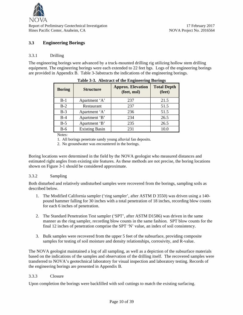
The engineering borings were advanced by a truck-mounted drilling rig utilizing hollow stem drilling equipment. The engineering borings were each extended to 22 feet bgs. Logs of the engineering borings are provided in Appendix B. Table 3-3abstracts the indications of the engineering borings.
Table 3-3. Abstract of the Engineering Borings
Boring Structure Approx. Elevation (feet, msl)
Total Depth (feet)
B-1 Apartment ‘A’ 237 21.5 B-2 Restaurant 237 51.5 B-3 Apartment ‘A’ 236 51.5 B-4 Apartment ‘B’ 234 26.5 B-5 Apartment ‘B’ 235 26.5 B-6 Existing Basin 231 10.0
Notes: 1. All borings penetrate sandy young alluvial fan deposits. 2. No groundwater was encountered in the borings.
Boring locations were determined in the field by the NOVA geologist who measured distances and estimated right angles from existing site features. As these methods are not precise, the boring locations shown on Figure 3-1 should be considered approximate.
3.3.2 Sampling
Both disturbed and relatively undisturbed samples were recovered from the borings, sampling soils as described below.
1. The Modified California sampler (‘ring sampler’, after ASTM D 3550) was driven using a 140-pound hammer falling for 30 inches with a total penetration of 18 inches, recording blow counts for each 6 inches of penetration.
2. The Standard Penetration Test sampler (‘SPT’, after ASTM D1586) was driven in the same manner as the ring sampler, recording blow counts in the same fashion. SPT blow counts for the final 12 inches of penetration comprise the SPT ‘N’ value, an index of soil consistency.
3. Bulk samples were recovered from the upper 5 feet of the subsurface, providing composite samples for testing of soil moisture and density relationships, corrosivity, and R-value.
The NOVA geologist maintained a log of all sampling, as well as a depiction of the subsurface materials based on the indications of the samples and observation of the drilling itself. The recovered samples were transferred to NOVA’s geotechnical laboratory for visual inspection and laboratory testing. Records of the engineering borings are presented in Appendix B.
3.3.3 Closure
Upon completion the borings were backfilled with soil cuttings to match the existing surfacing.
Report of Preliminary Geotechnical Investigation 17 February 2017 Hines Pacific Center, Anaheim, CA NOVA Project No. 2016564
Page 11 of 39
3.4 Percolation Testing
3.4.1 General
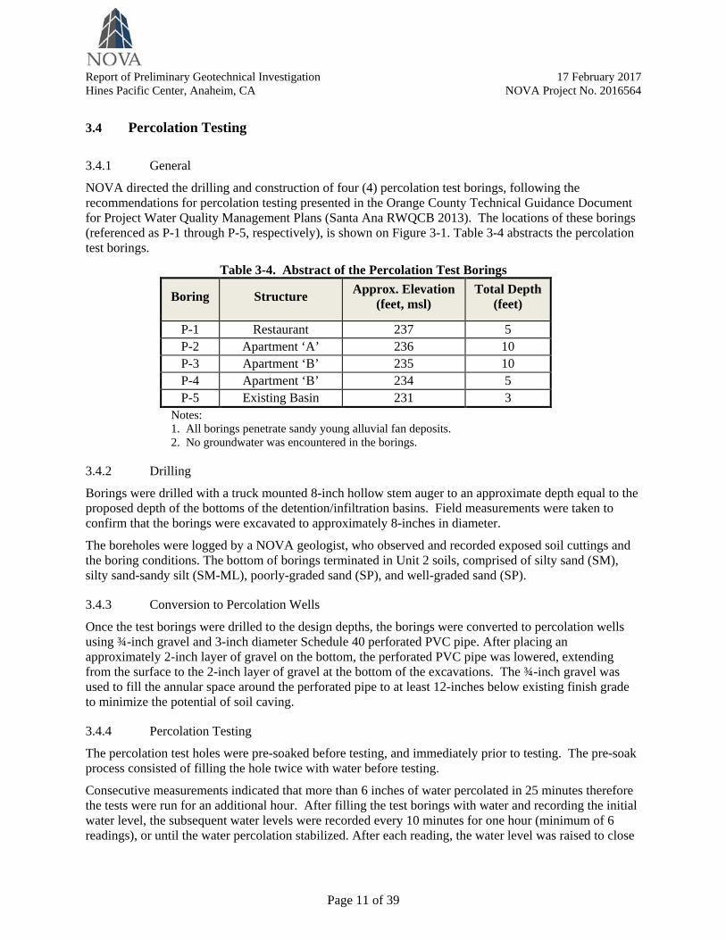
NOVA directed the drilling and construction of four (4) percolation test borings, following the recommendations for percolation testing presented in the Orange County Technical Guidance Document for Project Water Quality Management Plans (Santa Ana RWQCB 2013). The locations of these borings (referenced as P-1 through P-5, respectively), is shown on Figure 3-1. Table 3-4 abstracts the percolation test borings.
Table 3-4. Abstract of the Percolation Test Borings
Boring Structure Approx. Elevation (feet, msl)
Total Depth (feet)
P-1 Restaurant 237 5 P-2 Apartment ‘A’ 236 10 P-3 Apartment ‘B’ 235 10 P-4 Apartment ‘B’ 234 5 P-5 Existing Basin 231 3
Notes: 1. All borings penetrate sandy young alluvial fan deposits. 2. No groundwater was encountered in the borings.
3.4.2 Drilling
Borings were drilled with a truck mounted 8-inch hollow stem auger to an approximate depth equal to the proposed depth of the bottoms of the detention/infiltration basins. Field measurements were taken to confirm that the borings were excavated to approximately 8-inches in diameter.
The boreholes were logged by a NOVA geologist, who observed and recorded exposed soil cuttings and the boring conditions. The bottom of borings terminated in Unit 2 soils, comprised of silty sand (SM), silty sand-sandy silt (SM-ML), poorly-graded sand (SP), and well-graded sand (SP).
3.4.3 Conversion to Percolation Wells
Once the test borings were drilled to the design depths, the borings were converted to percolation wells using ¾-inch gravel and 3-inch diameter Schedule 40 perforated PVC pipe. After placing an approximately 2-inch layer of gravel on the bottom, the perforated PVC pipe was lowered, extending from the surface to the 2-inch layer of gravel at the bottom of the excavations. The ¾-inch gravel was used to fill the annular space around the perforated pipe to at least 12-inches below existing finish grade to minimize the potential of soil caving.
3.4.4 Percolation Testing
The percolation test holes were pre-soaked before testing, and immediately prior to testing. The pre-soak process consisted of filling the hole twice with water before testing.
Consecutive measurements indicated that more than 6 inches of water percolated in 25 minutes therefore the tests were run for an additional hour. After filling the test borings with water and recording the initial water level, the subsequent water levels were recorded every 10 minutes for one hour (minimum of 6 readings), or until the water percolation stabilized. After each reading, the water level was raised to close

Report of Preliminary Geotechnical Investigation 17 February 2017 Hines Pacific Center, Anaheim, CA NOVA Project No. 2016564
Page 12 of 39
to the previous water level to maintain a near constant head before each reading. Water depth measurements were obtained from the top of the pipe.
The findings of the percolation testing are discussed in Section 7. Records related to the percolation testing are provided in Appendix D.
3.5 Geotechnical Laboratory Testing
3.5.1 General
Soil samples recovered from the engineering borings were transferred to NOVA’s geotechnical laboratory where a geotechnical engineer reviewed the soil samples and the field logs. Representative soil samples were selected and tested in NOVA’s materials laboratory to check visual classifications and to determine pertinent engineering properties. Records of the testing are provided in Appendix C.
3.5.2 Mechanical Characteristics
The mechanical characteristics (strength and compressibility) of the soils were tested as described below.
1. Direct Shear. A single sample (Boring 1 at 2 feet depth) from the near surface Unit 1 sands was tested in direct shear after ASTM D3080. This testing indicated an angle of internal friction of 28° and apparent cohesion of 5 psf.
2. Resistance Value. A bulk sample of soils representative of Unit 1 was tested to measure the potential strength of this soil for use as the subgrade in new pavements. The R-Value testing was completed after ASTM D2844, indicating R = 58.
3. Moisture-Density. Associated with the R-Value testing, moisture-density after ASTM D1557 Method A (the ‘Modified Proctor’) was undertaken to project the behavior of the Unit 1 soil when used in earthwork. This testing is summarized on Table 3-5.
Table 3-5. Summary of the Modified Proctor Moisture Density Testing
Sample Description Maximum Dry Density (lb/ft3)
Optimum Moisture Content
B-2 at 3 feet depth Brown silty sand-sandy silt (SM-ML) 131.3 8.6
B-3 at 3 feet depth Brown poorly graded-sand (SP) 129.0 9.2
Note: testing after ASTM D1557 Method A
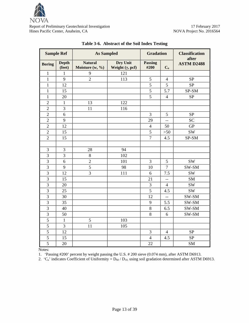
3.5.3 Index
The visual classifications were further evaluated by performing moisture content and grain size tests. Table 3-6 (following page) provides a summary of this testing.
3.6 Corrosivity Testing
Resistivity, sulfate content, and chloride contents were determined to estimate the potential corrosivity of the soils. These chemical tests were performed on a representative sample of the near surface soils by Clarkson Laboratory and Supply, Inc. The findings of this testing are discussed in Section 6.
Report of Preliminary Geotechnical Investigation 17 February 2017 Hines Pacific Center, Anaheim, CA NOVA Project No. 2016564
Page 13 of 39
Table 3-6. Abstract of the Soil Index Testing
Sample Ref As Sampled Gradation Classification after
ASTM D2488 Boring Depth (feet)
Natural Moisture (w, %)
Dry Unit Weight (γ, pcf)
Passing #200
Cu
1 1 9 121 1 9 2 113 5 4 SP 1 12 5 5 SP 1 15 5 5.7 SP-SM 1 20 5 4 SP 2 1 13 122 2 3 11 116 2 6 3 5 SP 2 9 29 -- SC 2 12 4 50 GP 2 15 5 >50 SW 2 15 7 4.5 SP-SM
3 3 28 94 3 3 8 102 3 6 2 101 3 5 SW 3 9 5 98 10 7 SW-SM 3 12 3 111 6 7.5
SW 3 15 21 -- SM 3 20 3 4 SW 3 25 5 4.5
SW 3 30 12 -- SW-SM 3 35 9 5.5 SW-SM 3 40 8 6.5 SW-SM 3 50 8 6 SW-SM 5 1 5 103 5 3 11 105 5 12 3 4 SP 5 15 4 4.5 SP 5 20 22 SM
Notes: 1. ‘Passing #200’ percent by weight passing the U.S. # 200 sieve (0.074 mm), after ASTM D6913. 2. ‘Cu’ indicates Coefficient of Uniformity = D60 / D10, using soil gradation determined after ASTM D6913.

Report of Preliminary Geotechnical Investigation 17 February 2017 Hines Pacific Center, Anaheim, CA NOVA Project No. 2016564
Page 14 of 39
4.0 SITE CONDITIONS
4.1 Geologic Setting
4.1.1 Regional
The project area is located within in the southern part of the Los Angeles Basin in the Peninsular Ranges Geomorphic Province, west of the east-to-west-trending Chino Hills.
The Peninsular Ranges Geomorphic Province is a series of mountain ranges separated by northwest-trending valleys, which characterizes the southwest portion of California. This geomorphic province encompasses an area that extends about 900 miles from the Transverse Ranges and the Los Angeles Basin south to the southern tip of Baja California. The province varies in width from approximately 30 to 100 miles. The surface topography is characterized geomorphically by eroded and dissected mesa terrain.
4.1.2 Site Specific
The site is located within alluvial/floodplain deposits associated with the Santa Ana River. As consequence, the soils of concern for this development are relatively younger in geologic age, and may be wide-ranging in gradation (i.e., ranging from sandy to clayey). Figure 4-1 reproduces geologic mapping of the site area, from which it can be seen that the site is underlain by Quaternary-aged alluvial deposits.
Figure 4-1. Geologic Mapping of the Site Vicinity (note: ‘Qyf’ indicates alluvial fan deposits of Quaternary age)

Report of Preliminary Geotechnical Investigation 17 February 2017 Hines Pacific Center, Anaheim, CA NOVA Project No. 2016564
Page 15 of 39
4.2 Faulting and Seismicity
Like all of the metropolitan Los Angeles area, the site will be subject to relatively intensive ground shaking resulting from earthquakes sourced from any of several major faults in the area. The site is reasonably proximate to the Whittier and Chino faults, the upper branches of the Elsinore Fault Zone. These faults capable of generating large magnitude seismic events. The peak ground acceleration adjusted for site effects (PGAM)for the risk-targeted Maximum Considered Earthquake (MCER) is PGAM = 0.60 g.
Figure 4-2 maps the occurrence of nearby major faulting segments in the vicinity of the site.
Figure 4-2. Faulting in the Site Vicinity (source:
To protect structures from the hazard of surface ground rupture along a fault line, the California Geological Survey (CGS), under the state mandated Alquist-Priolo Act of 1972, has delineated “Earthquake Fault Zones” along active or potentially active faults. A fault is considered active if there is evidence of movement along one or more of its segments in the last 11,000 years, which is either directly observable or inferred. A well-defined fault is one in which its trace can be clearly detected by a trained geologist as a physical feature at or just below the ground surface. A well-defined fault may be identified by either direct or indirect methods. If a site is in an Earthquake Fault Zone, a detailed fault investigation is required prior to construction.
The project site is not in an Earthquake Fault Zone and there are no faults known to exist or mapped crossing the site. Review of the literature indicates there are no known active faults on or near the Pacific Center site. NOVA did not observe evidence of historic ground rupture during reconnaissance of the site.

Report of Preliminary Geotechnical Investigation 17 February 2017 Hines Pacific Center, Anaheim, CA NOVA Project No. 2016564
Page 16 of 39
4.3 Site Conditions
4.3.1 Surface
The three parcels that are addressed by this report site area comprise about 5.5-acres. The entire Pacific Center property- including parcels already developed- covers about 15.5 acres. The ground surface across all parcels is relatively level. The elevation of the separate parcels ranges from about +236 feet msl to +240 feet msl.
As may be seen by review of Figure 2-1, most of the area of the subject properties is developed.
• The parcel planned to include Apartment ‘A’ vacant, covered in equal parts by asphalt pavement for parking and landscaped areas.
• The parcel planned to include Apartment ‘B’ includes a single-story commercial structure surrounded by asphalt surfacing.
• The parcel planned to include the restaurant is asphalt surfaced to provide parking for nearby commercial structures.
Figure 4-3depicts surface conditions at the Apartment ‘A’ parcel.
Figure 4-3. Surface Conditions, Apartment ‘A’ Parcel, Looking South From La Palma Avenue

Report of Preliminary Geotechnical Investigation 17 February 2017 Hines Pacific Center, Anaheim, CA NOVA Project No. 2016564
Page 17 of 39
4.3.2 Subsurface
Though the three parcels under consideration by this study are separated by distances (center-to-center) of typically 600 feet, the same subsurface conditions were encountered at each of the parcels, For the purposes of this report, the subsurface the parcels addressed by this may be generalized to occur as the sequence of soils described below.
1. Unit 1, Fill. A thin veneer of undocumented artificial fill (Qaf) covers the entire site. The fill ranges from 2 feet to 3 feet in thickness. The soil characteristically silty sands-sandy silt (SM-ML), of medium dense to dense consistency.
2. Unit 2, Alluvial Sands. Beneath the Unit 1 fill, the entire site is underlain by alluvial sands of characteristically dense consistency. SPT blow counts (‘N’) are typically in the range 15 < N < 50 blows/foot. Shear wave velocities average over 800 ft/sec below a depth of about 20 feet, suggestive of a dense to very dense soil. As is shown on Figure 4-4, below the upper few feet of this unit the average CPT tip resistance (qc) well exceeds 100 tons per square foot (tsf), These dense Holocene-aged sands extend to depths greater than 75 feet across the site.
Figure 4-4. Average CPT Tip Resistance (qc) vs. Depth
4.3.3 Groundwater
Ground water was not encountered in the borings by NOVA. It is expected that groundwater does not occur within 60 feet of the existing ground surface.
Though groundwater was not encountered by this exploration, groundwater levels may rise in the future. The area of the site is actively managed by the Orange County Water District (OCWD) as a part of its programs to preserve and restore groundwater resources within Orange County. Figure 4-5 (following page) depicts the location of surface water recharge facilities (referenced as ‘basins’ and ‘lakes’) that are located near the site.

Report of Preliminary Geotechnical Investigation 17 February 2017 Hines Pacific Center, Anaheim, CA NOVA Project No. 2016564
Page 18 of 39
Figure 4-5. OCWD Surface Water Recharge Facilities near the Site
(source: OCWD 2015)
The future effects of OCWD’s efforts toward maintenance and restoration of ground water levels has been considered herein, as described below.
• If groundwater levels rise to within about 50 feet or higher near the ground surface, this rise could affect liquefaction potential in a seismic event. This potential is discussed in Section 5.3.2.
• Rising and declining groundwater levels affect ground surface elevations. This consideration is discussed in Section 5.4.3.
4.3.4 Surface Water
No surface water was evident on the site at the time of NOVA’s work. There is no visual evidence of recent occurrences with surface water (e.g., seeps, springs, eroded gullies, rilling erosion, etc.).

Report of Preliminary Geotechnical Investigation 17 February 2017 Hines Pacific Center, Anaheim, CA NOVA Project No. 2016564
Page 19 of 39
5.0 REVIEW OF GEOLOGIC AND SOIL HAZARDS
5.1 Overview
This section provides review of soil and geologic hazards common to this region of California, considering each for its potential to affect the site.
The primary geologic and seismic hazard during the life of the planned development is the likelihood of moderate-to-severe ground motions in response to either a local moderate or more distant large-magnitude earthquake. While there is no risk of liquefaction or related seismic phenomena based on our evaluation of the current data, strong ground motions could affect the site.
5.2 Geologic Hazards
5.2.1 Strong Ground Motion
The site is not located within a currently designated Alquist-Priolo Earthquake Zone (Hart and Bryant, 2007). No known active faults are mapped on the site. The site is reasonably proximate to the Whittier and Chino faults, the upper branches of the Elsinore Fault Zone. These faults capable of generating large magnitude seismic events.
The peak ground acceleration adjusted for site effects (PGAM) for the risk-targeted Maximum Considered Earthquake (MCER) is PGAM = 0.60 g.
5.2.2 Fault Rupture
As is discussed in Section 4, there are no known active faults on or near the site. The potential for surface rupture at the site is thus considered low. Shallow ground rupture due to shaking from distant seismic events is not considered a significant hazard, although it is a possibility at any site.
5.2.3 Landslides
As used herein, ‘landslide’ describes downslope displacement of a mass of rock, soil, and/or debris by sliding, flowing, or falling. Such mass earth movements are greater than about 10 feet thick and larger than 300 feet across. Landslides typically include cohesive block glides and disrupted slumps that are formed by translation or rotation of the slope materials along one or more slip surfaces.
The causes of classic landslides start with a preexisting condition-characteristically, a plane of weak soil or rock- inherent within the rock or soil mass. Thereafter, movement may be precipitated by earthquakes, wet weather, and changes to the structure or loading conditions on a slope (e.g., by erosion, cutting, filling, release of water from broken pipes, etc.).
The site is set in a relatively flat area, such that NOVA considers the landslide hazard to be ‘negligible’ for the site and the surrounding area in their current condition.

Report of Preliminary Geotechnical Investigation 17 February 2017 Hines Pacific Center, Anaheim, CA NOVA Project No. 2016564
Page 20 of 39
5.3 Soil Hazards
5.3.1 Embankment Stability
As used herein, ‘embankment stability’ is intended to mean the safety of localized natural or man-made embankments against failure. Unlike landslides described above, embankment stability can include smaller scale slope failures such as erosion-related washouts and more subtle, less evident processes such as slope ‘creep.’
No new slopes are planned as part of the proposed development and none existing. There is no risk of embankment instability.
5.3.2 Liquefaction
“Liquefaction” refers to the loss of soil strength during a seismic event. The phenomenon is observed in areas that include a shallow water table and coarse grained (i.e., ‘sandy’) soils of loose to medium dense consistency. The ground motions increase soil water pressures, decreasing grain-to-grain contact among the soil particles, causing the soil mass to lose strength. Liquefaction resistance increases with increasing soil density, plasticity (associated with clay-sized particles), geologic age, cementation, and stress history.
Because of the low ground water levels (greater than 60 feet bgs) and dense to very dense nature of the soils, the soils at this site will not experience liquefaction during a strong seismic event (M > 7, PGA = 0.6).
However, as is discussed in Section 4.3.3, the OCWD manages a program to preserve and restore groundwater resources within Orange County. As is depicted on Figure 4-5 surface water recharge facilities that are located very near the site (less than 800 feet distant). NOVA has considered that groundwater levels may rise above current levels during the lives of the planned structures. Two cases of groundwater rise have been considered, evaluating each in the event of a seismic event of M = 7.2, PGA = 0.6.
• Case 1: groundwater rising to 50 feet below ground surface (i.e., to about El +188 feet msl). • Case 2: groundwater rising to 35 feet below ground surface (i.e., to about El +203 feet msl).
Analysis of these cases using the CPT data presented in Figure 4-4 shows that the seismic event will effect about 0.5 inches of settlement, with most of this movement occurring within the near surface sands. Figure 5-1 (following page) provides output from the Case 2 analysis.
5.3.3 Seismically Induced Settlement
During a strong seismic event, seismically induced settlement can occur within unsaturated granular soils, separate from liquefaction. Such settlement is often non-uniformly distributed, which can result in differential settlement.
NOVA has evaluated the case of a strong seismic event (M > 7, PGA = 0.6). The site-wide seismically induced settlement from such an event will be to on the order of ½ inch. The related differential settlement will be about ¼ inch over a span of 40 feet.
5.3.4 Lateral Spreading
Lateral spreading is a phenomenon in which large blocks of intact, non-liquefied soil move downslope on a liquefied soil layer. Lateral spreading is often a regional event. For lateral spreading to occur, a liquefiable soil zone must be laterally continuous, unconstrained laterally, and free to move along sloping

Report of Preliminary Geotechnical Investigation 17 February 2017 Hines Pacific Center, Anaheim, CA NOVA Project No. 2016564
Page 21 of 39
ground. Due to the negligible potential for liquefaction and the laterally confined topography of the site, the potential for lateral spreading is non-existent.
Figure 5-1. Liquefaction Analysis, Groundwater at 35 Feet, M = 7.2, a = 0.6g
5.3.5 Expansive Clays
These soils are characterized by their ability to undergo significant volume changes (shrinking or swelling) due to variations in moisture content. These volume changes can be damaging to structures. Nationally, the value of property damage caused by expansive soils is exceeded only by that caused by termites. In consideration of the largely sandy near surface soils, expansive soils will not be an issue for this project.

Report of Preliminary Geotechnical Investigation 17 February 2017 Hines Pacific Center, Anaheim, CA NOVA Project No. 2016564
Page 22 of 39
5.3.6 Collapsible Soils
Collapsible soils occur with some frequency in arid climates such as this area of California. Collapsible soils would have been removed during the original site grading. Collapsible soils do not constitute a hazard to site development.
5.3.7 Corrosive Soils
Chemical testing of the near surface soils indicates the soils contain low concentrations of soluble sulfates (110ppm), and chlorides (32ppm). Saturated soil resistivity is 4,900 Ohm-cm, with a pH of 8.5. The tested soils should not be corrosive to construction materials, either buried metals or embedded concrete. Section 6 addresses this consideration in more detail.
5.4 Other Hazards
5.4.1 Flood
The site is not located within a FEMA-designated flood zone, designated as Flood “Zone X” (FEMA, Map 06059C0152J, effective on12/03/2009). Zone X describes “Areas of 0.2% annual chance flood; areas of 1% annual chance flood with average depths of less than 1 foot or with drainage areas less than 1 square mile; and areas protected by levees from 1% annual chance flood.” Figure 5-2 reproduces the portion of Map Number 06059C0152J that includes the site.
Figure 5-2. Portion of FIRM Number 06059C0152J that Includes the Site (source: FEMA 2016, found at https://msc.fema.gov/portal/)
Report of Preliminary Geotechnical Investigation 17 February 2017 Hines Pacific Center, Anaheim, CA NOVA Project No. 2016564
Page 23 of 39
5.4.2 Inundation
Prado Dam, a flood control and water conservation structure is located at the upper end of Lower Santa Ana River Canyon, a natural constriction controlling 2,233 square miles of the 2,450-square mile Santa Ana River watershed. The earth embankment dam, constructed by the Corps of Engineers in 1941, is 11.5 miles west of Pacific Center. At full pool, the dam impounds about 360,000 acre-feet of water.
The site is mapped as being located within the area that would be inundated in the event of a failure of Prado Dam (N&M 2001). The depth to which inundation would occur is not cited in N&M 2001, but is likely on the order of three feet or less.
5.4.3 Subsidence and Recharge
Ground subsidence related to human activities is common in southern California. Within Orange County, subsidence has occurred primarily as a result of withdrawal of groundwater. This pumping has historically affected the Orange County area by lowering ground surface levels.
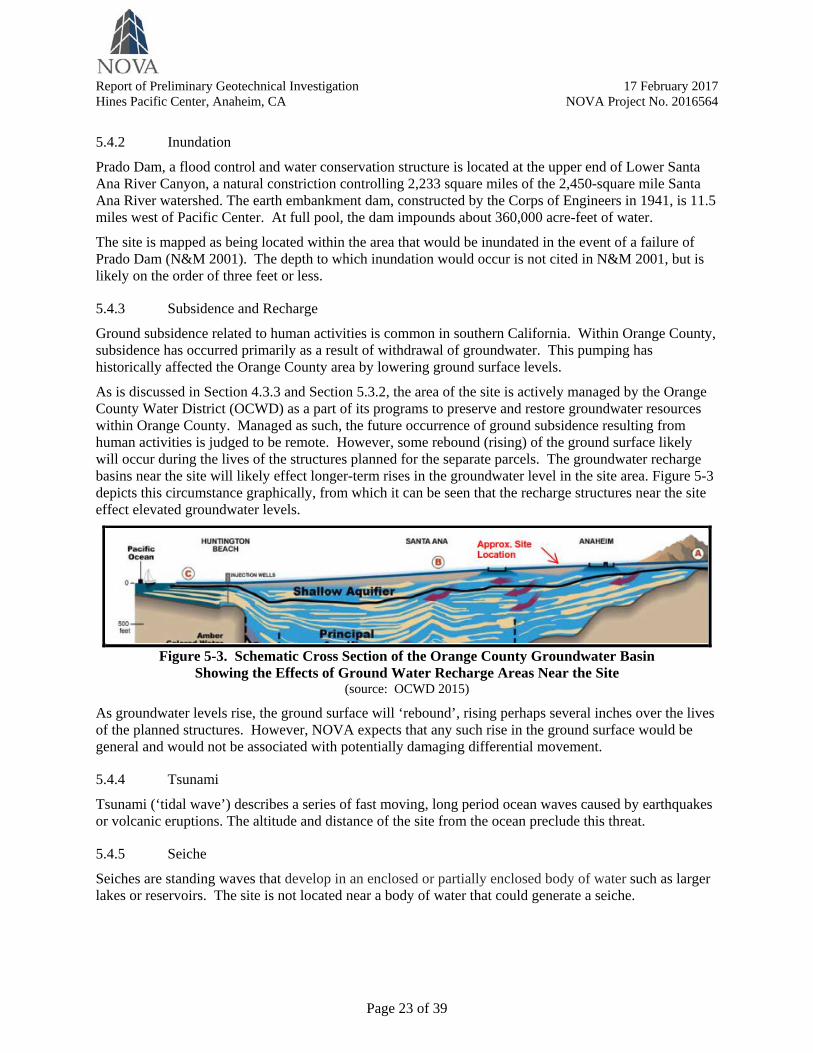
As is discussed in Section 4.3.3 and Section 5.3.2, the area of the site is actively managed by the Orange County Water District (OCWD) as a part of its programs to preserve and restore groundwater resources within Orange County. Managed as such, the future occurrence of ground subsidence resulting from human activities is judged to be remote. However, some rebound (rising) of the ground surface likely will occur during the lives of the structures planned for the separate parcels. The groundwater recharge basins near the site will likely effect longer-term rises in the groundwater level in the site area. Figure 5-3 depicts this circumstance graphically, from which it can be seen that the recharge structures near the site effect elevated groundwater levels.
Figure 5-3. Schematic Cross Section of the Orange County Groundwater Basin
Showing the Effects of Ground Water Recharge Areas Near the Site (source: OCWD 2015)
As groundwater levels rise, the ground surface will ‘rebound’, rising perhaps several inches over the lives of the planned structures. However, NOVA expects that any such rise in the ground surface would be general and would not be associated with potentially damaging differential movement.
5.4.4 Tsunami
Tsunami (‘tidal wave’) describes a series of fast moving, long period ocean waves caused by earthquakes or volcanic eruptions. The altitude and distance of the site from the ocean preclude this threat.
5.4.5 Seiche
Seiches are standing waves that develop in an enclosed or partially enclosed body of water such as larger lakes or reservoirs. The site is not located near a body of water that could generate a seiche.

Report of Preliminary Geotechnical Investigation 17 February 2017 Hines Pacific Center, Anaheim, CA NOVA Project No. 2016564
Page 24 of 39
6.0 EARTHWORK AND FOUNDATIONS
6.1 Overview
6.1.1 Shallow Foundations
Based upon the indications of the field and laboratory data developed for this investigation, as well as review of previously developed subsurface information, the sites addressed by this report are suitable for economic development of the planned apartments and restaurant on shallow foundations provided the geotechnical recommendations described herein are followed. Section 6.5 addresses design criteria for shallow foundations.
6.1.2 Storm Water BMPs
Section 7 provides additional discussion of relevance to foundation design. As is discussed therein, subsurface conditions favor development of efficient stormwater infiltration BMPs. Such structures must be located such that ground saturated by infiltrating storm water does not threaten foundations or utilities.
6.1.3 Review of Final Design
NOVA should review the grading plan, foundation plan and geotechnical-related specifications as they become available to confirm that the recommendations presented in this report have been incorporated into the plans prepared for the project.
All earthwork related to site and foundation preparation should be completed under the observation of NOVA. NOVA cannot assume responsibility or liability for the recommendations of this report if NOVA does not perform construction observation.
The subsections following provide geotechnical recommendations for the planned development as it is now understood. It is intended that these recommendations provide sufficient geotechnical information to develop the project in general accordance with 2013 California Building Code (CBC) requirements.
6.2 Seismic Design Parameters
6.2.1 Site Class
The Site Class has been determined from ASCE 7, Table 20.3-1. Based on estimated average N-values in the upper 100 feet of the soil/rock profile, the site corresponds to a Site Class D.
6.2.2 Seismic Design Parameters
Table 6-1(following page) provides seismic design parameters for the site in accordance with 2013 CBC and mapped spectral acceleration parameters.

Report of Preliminary Geotechnical Investigation 17 February 2017 Hines Pacific Center, Anaheim, CA NOVA Project No. 2016564
Page 25 of 39
Table 6-1. Seismic Design Parameters, ASCE 7-10
Parameter Value
Site Soil Class D Site Latitude (decimal degrees) 33.8537 Site Longitude (decimal degrees) -117.83811 Site Coefficient, Fa 1.000 Site Coefficient, Fv 1.500 Mapped Short Period Spectral Acceleration, SS 1.571 g Mapped One-Second Period Spectral Acceleration, S1 0.600 g Short Period Spectral Acceleration Adjusted For Site Class, SMS 1.571 g One-Second Period Spectral Acceleration Adjusted For Site Class, SM1 0.900 g Design Short Period Spectral Acceleration, SDS 1.047 g Design One-Second Period Spectral Acceleration, SD1 0.600 g
Source: U.S. Seismic Design Maps, found at http://earthquake.usgs.gov/designmaps/us/application.php
6.3 Corrosivity and Sulfates
6.3.1 Corrosivity
Electrical resistivity, chloride content, and pH level are all indicators of the soil’s tendency to corrode ferrous metals. Chemical tests were performed on representative samples by Clarkson Laboratory and Supply, Inc. of Chula Vista. The results of the testing are tabulated on Table 6-2.
Table 6-2. Summary of Corrosivity Testing of the Near Surface Soil
Caltrans considers a site to be corrosive if one or more of the following conditions exist for representative soil and/or water samples taken at the site:
• chloride concentration is 500 parts per million (ppm) or greater; • sulfate concentration is 2,000 ppm (0.2%) or greater; or, • the pH is 5.5 or less.
Based on the Caltrans criteria, the on-site soils would not be considered ‘corrosive’ to buried metals. Records of this testing are provided in Appendix C. These records include estimates of the life expectancy of buried metal culverts of varying gauge.
Parameter Units Value pH standard unit 8.5 Resistivity Ohm-cm 4,900 Water Soluble Chloride ppm 32 Water Soluble Sulfate ppm 110

Report of Preliminary Geotechnical Investigation 17 February 2017 Hines Pacific Center, Anaheim, CA NOVA Project No. 2016564
Page 26 of 39
6.3.2 Sulfates and Concrete
As shown on Table 6-2, the soil sample tested indicated water-soluble sulfate (SO4) content of 110 parts per million (‘ppm,’ 0.011% by weight). With SO4<0.10 percent by weight, the American Concrete Institute (ACI) 318-08 considers a soil to have no potential (S0) for sulfate attack. Table 6-3 reproduces the Exposure Categories considered by ACI. Table 6-3. Exposure Categories and Requirements for Water-Soluble Sulfates
Exposure Category Class
Water-Soluble Sulfate (SO4) In Soil (percent by weight)
Cement Type (ASTM C150)
Max Water-Cement Ratio
Min. f’c (psi)
Not
S0 SO4< 0.10 - - - Moderate S1 0.10 ≤ SO4< 0.20 II 0.50 4,000 Severe S2 0.20 ≤ SO4 ≤ 2.00 V 0.45 4,500 Very severe S3 SO4> 2.0 V + pozzolan 0.45 4,500
Adapted from: ACI 318-08, Building Code Requirements for Structural Concrete
6.3.3 Limitations
Testing to determine several chemical parameters that indicate a potential for soils to be corrosive to construction materials are traditionally completed by the Geotechnical Engineer, comparing testing results with a variety of indices regarding corrosion potential. Like most geotechnical consultants, NOVA does not practice in the field of corrosion protection, since this is not specifically a geotechnical issue. Should more information be required, a specialty corrosion consultant should be retained to address these issues.
6.4 Earthwork
6.4.1 General
As is discussed in Section 2, NOVA expects that earthwork for the new structures will consist of minor fine grading, and excavations for foundations and utilities. Based upon the indications of the field exploration, the Unit 1 and Unit 2 soils can be readily excavated with conventional excavation equipment.
Earthwork should be performed in accordance with Section 300 of the most recent approved edition of the “Standard Specifications for Public Works Construction” and “Regional Supplement Amendments.” All fill and backfill should be compacted to a minimum of 90 percent relative compaction after ASTM D1557 (the ‘modified Proctor’) following moisture conditioning to 2% above the optimum moisture content. Fill placed in loose lifts no thicker than the ability of the compaction equipment to thoroughly densify the lift. For most construction equipment, this limit loose lifts to on the order of 8-inches or less.
6.4.2 Select Fill
Both the sandy Unit 1 and Unit 2 soil will be suitable for use as fill. Should a sufficient amount of this material not be available, a ‘select’ soil should be imported. ‘Select’ soil should be a mineral soil free of organics, classified as SM, GM or GW after ASTM D2488, with the characteristics listed below:
• at least 60 percent by weight finer than ¼-inch;
• maximum particle size of 6 inches; and,
• EI(after ASTM D4829) of less than 20.

Report of Preliminary Geotechnical Investigation 17 February 2017 Hines Pacific Center, Anaheim, CA NOVA Project No. 2016564
Page 27 of 39
All select fill should be compacted to 90% relative compaction after ASTM D1557.
6.4.3 Site Preparation
Pavements, utilities and vegetation should be removed from areas planned for new structures before the start of grading operations. Abandoned utilities and improvements, vegetation, and debris and rubble should be removed and properly disposed off-site.
Abandoned underground utilities should either be excavated and the trenches backfilled or the lines completely filled with sand-cement slurry.
6.4.4 Surface Densification
Following clearing and grubbing, the near surface soils should be improved using the following general approach.
1. Step 1, Excavation. Remove the upper three feet of the existing soils (Unit 1/Unit 2) below the design finished pad grade or one foot below the deepest footing excavation, whichever is greater. The removed soils may be stockpiled for later re-use. The bottom of all removals should be approved by a representative of NOVA.
2. Step 2, Moisture Conditioning. The exposed soils (bottom of removal) should be moisture conditioned to 2% above optimum moisture content (with reference to ASTM D1557) to a depth of 12 inches.
3. Step 3, Densification. The exposed soils at the bottom of removals should be densified by compaction using a vibratory drum roller weighing a minimum of 16 tons, completing at least five passes in the forward direction over the areas to support foundations and slabs. Quality control testing should be undertaken to confirm that the upper 12 inches of exposed soil is densified to at least 90% relative compaction after ASTM D 1557.
4. Step 4, Proof-Rolling. The entire area of expose soil should be proof rolled by a heavy wheeled vehicle (for example, a loaded dump truck). Areas that appear soft during the proof rolling process should be re-densified/improved.
5. Step 5, Replacement. The stockpiled soils should be replaced as engineered fill, densified to at least 90% relative compaction after ASTM D1557 at a moisture content 2% above optimum.
6.5 Shallow Foundations for the Apartments, Restaurant and Parking Garages
6.5.1 General
The apartments, restaurant and parking garages may be supported on shallow foundations. The following subsections provide recommendations for these foundations. Shallow foundations designed as described in this section will settle on the order of 1 to 1.5 inches, with 80% or more of this settlement occurring during construction. Post construction settlement should be on the order of 0.5 inches, with post construction differential settlement on the order of 0.3 inches in 40 feet. Note also, as is discussed in Section 5.3, as major seismic event will effect an additional 0.5 inches settlement, with differential settlement on the order of 0.2 inches in 40 feet.
Report of Preliminary Geotechnical Investigation 17 February 2017 Hines Pacific Center, Anaheim, CA NOVA Project No. 2016564
Page 28 of 39
6.5.2 Conventionally Reinforced Concrete Slab
A conventionally reinforced on-grade concrete slab, founded on soils improved as described above, may be designed using a modulus of subgrade reaction of 130 pounds per cubic inch (130 pci). NOVA recommends the on-grade slab be a minimum of 5 inches thick. The project structural engineer should recommend the reinforcement for the concrete slabs.
Minor cracking of concrete after curing due to drying and shrinkage is normal. Cracking is aggravated by a variety of factors, including high water/cement ratio, high concrete temperature at the time of placement, small nominal aggregate size, and rapid moisture loss due during curing. The use of low-slump concrete or low water/cement ratios can reduce the potential for shrinkage cracking.
To reduce the potential for excessive cracking, concrete slabs-on-grade should be provided with construction or ‘weakened plane’ joints at frequent intervals. Joints should be laid out to form approximately square panels.
6.5.3 Isolated and Continuous Foundations
Shallow foundations-isolated or continuous footings-may be employed as described below.
Isolated Foundations
Isolated foundations may be designed for an allowable contact stress of 3,500 psf. This value may be increased by one-third for transient loads such as wind and seismic. These foundation units should have a minimum width of 30 inches regardless of contact stress, embedded a minimum of 30 inches below surrounding grade.
Continuous Foundations
Continuous foundations may be designed for an allowable contact stress of 2,800 psf, for footings a minimum of 18 inches in width and embedded 24 inches below surrounding grade. This bearing value may be increased by one-third for transient loads such as wind and seismic.
Resistance to Lateral Loads
Lateral loads to shallow foundations may be resisted by passive earth pressure against the face of the footing, calculated as a fluid density of 300 psf per foot of depth, neglecting the upper 1 foot of soil below surrounding grade in this calculation. Alternatively, a coefficient of friction of 0.35 between soil and the concrete base of the footing may be used with dead loads. Because of the strain incompatibility, passive resistance and concrete-soil friction will not act in concert.
6.5.4 Moisture Barrier
Need
The recommendations in this subsection address moisture protection of concrete floor slabs. Not all floor slabs may need such protection. However, such protection may be necessary for floor slabs that carry moisture sensitive items, such as coverings or equipment.
Capillary Break
The requirements for a capillary break (‘sand layer’) should be determined in accordance with ACI Publication 302 “Guide for Concrete Floor and Slab Construction.”

Report of Preliminary Geotechnical Investigation 17 February 2017 Hines Pacific Center, Anaheim, CA NOVA Project No. 2016564
Page 29 of 39
A “capillary break” may consist of a 4-inch thick layer of compacted, well-graded gravel or crushed stone should be placed below the floor slab. This porous fill should be clean coarse sand or sound, durable gravel with not more than 5 percent coarser than the 1-inch sieve or more than 10 percent finer than the No. 4 sieve, such as AASHTO Coarse Aggregate No. 57.
Vapor Membrane
Membranes set below floor slabs in should be rugged enough to withstand construction. If a vapor barrier is desired, a minimum 15-mil polyethylene membrane should be placed over the porous fill to preclude floor dampness.
NOVA recommends that a minimum 15-mil low permeance vapor membrane be used. For example, Carlisle-CCW produces the Blackline 400® underslab, vapor and air barrier, a 15-mil low density polyethylene (LDPE) rated at 0.012 perms after ASTM E96.
Limitations of This Recommendation
Recommendation for moisture barriers contained in this subsection are traditionally included with geotechnical foundation recommendations, though these requirements are primarily the responsibility of the Structural Engineer or Architect.
If there is particular concern regarding moisture sensitive materials or equipment to be placed above the slab-on-grade, a qualified person (for example, such as the flooring subcontractor and/or Structural Engineer) should be consulted to evaluate the general and specific moisture vapor transmission paths and any impact on the proposed construction. NOVA does not practice in the field of moisture vapor transmission, since this is not specifically a geotechnical issue.
6.5.5 Apartments Connection with the Parking Garages
The parking garages that are associated with Apartment ‘A’ and Apartment ‘B’ should be structurally separated.
Approximately 80% of the 1 to 1.5 inches settlement anticipated for the apartments will occur during construction, allowing for the bulk of this movement to be ‘built out’ by construction. Post-construction settlement of the apartments will be less than 0.5 inch. Conversely, about half of the 1 to 1.5 inches settlement anticipated for the parking garage will occur during construction. The remainder will occur as the parking structure is utilized.
Design for connections between the apartment structures and the parking garage should be flexible enough to accommodate a differential movement of about 1-inch between the structures.

Report of Preliminary Geotechnical Investigation 17 February 2017 Hines Pacific Center, Anaheim, CA NOVA Project No. 2016564
Page 30 of 39
6.6 Control of Moisture Around Foundations
6.6.1 General
Design for shallow foundations for any structure should include care to control accumulations of moisture around and below foundations.
6.6.2 Erosion and Moisture Control During Construction
Surface water should be controlled during construction, via berms, gravel/sandbags, silt fences, straw wattles, siltation basins, positive surface grades, or other method to avoid damage to the finish work or adjoining properties. The Contractor should take measures to prevent erosion of graded areas until such time as permanent drainage and erosion control measures have been installed. After grading, all excavated surfaces should exhibit positive drainage and eliminate areas where water might pond.
6.6.3 Design
Drainage
Rainfall to roofs should be collected in gutters and discharged in a controlled manner through downspouts designed to drain away from foundations. Downspouts, roof drains or scuppers should discharge into splash blocks to slabs or paving sloped away from buildings.
Surface Grades
Proper surface and subsurface drainage will be required to minimize the potential of water seeping into the level of the bearing soils under the foundations, footings and floor slabs. In areas where sidewalks or paving do not immediately adjoin the structure, NOVA recommends that protective slopes be provided with a minimum grade away from structures of approximately 2 percent for at least 10 feet from the perimeter. A minimum gradient of 1 percent is recommended in hardscape areas. Earth swales should have a minimum gradient of 2 percent, directing drainage away from structures to approved drainage facilities.
6.6.4 Utilities
Design for Differential Movement
Underground piping within or near structures should be designed with flexible couplings to accommodate both ground and slab movement, so that minor deviations in alignment do not result in breakage or distress. Utility knockouts should be oversized to accommodate the potential for differential movement between foundations and the surrounding soil.
Backfill Above Utilities.
Excavations for utility lines, which extend under or near structural areas should be properly backfilled and compacted to at least 90 percent relative compaction after ASTM D1557. Utilities should be bedded and backfilled with an approved granular soil to a depth of at least one foot over the pipe. The Unit 1 and Unit 2 soils of this site will be suitable for such use. This backfill should be uniformly watered and compacted to a firm condition for pipe support.

Report of Preliminary Geotechnical Investigation 17 February 2017 Hines Pacific Center, Anaheim, CA NOVA Project No. 2016564
Page 31 of 39
6.7 Flatwork
Concrete flatwork may be founded within Unit 1 or Unit 2 soil densified to 90% relative compaction after ASTM D1557 to a depth of at least 12 inches below the base of the flatwork.
As is noted with regard to concrete floor slabs, cracking of concrete is normal. The use of low slump concrete can reduce the potential for shrinkage cracking. Additionally, construction joints can be used to improve the aesthetics of cracking.
Contraction/control joints may be placed in concrete slabs to control random cracking. Contraction control joints may be effectively used to control random cracking in concrete slabs. Such features placed in the concrete surface at predetermined locations create weakened planes where the concrete can crack in a straight line, allowing cracking to take place below the finished concrete surface.
6.8 Retaining Walls
6.8.1 General
NOVA is not aware of any current planning for retaining walls for above or permanent below grade construction. However, it is understood that such planning may change and that site retaining walls and/or below grade level walls may be part of the development. Accordingly, this section provides recommendations for design pressures for permanent walls.
6.8.2 Foundations
Foundations supporting retaining walls should be embedded at least 24 inches below lowest adjacent grade and have a minimum width of 24 inches. All footing should be supported on compacted soil per the recommendations presented in Section 6.4.4.
6.8.3 Lateral Pressures
Lateral earth pressures for wall design are provided on Table 6-4 as equivalent fluid weights, in psf/foot of wall height or pounds per cubic foot (pcf). These values do not contain a factor of safety, such that design should apply the applicable factors of safety and/or load factors during design.
Table 6-4. Lateral Earth Pressures
Loading Condition Equivalent Fluid Density (pcf) for
Level Backfill 2:1 Backfill Sloping Upwards
Active (wall movement allowed) 35 60 “At Rest” (no wall movement) 65 100 ‘Passive” (wall movement toward the soils) 260 220
Note A: ‘approved’ means select soil with EI < 50 after ASTM D4829. Note B: assumes wall includes appropriate drainage.
6.8.4 Seismic
Seismic earth pressures to fixed below grade walls should be applied with a rectangular stress distribution and calculated as Pseismic = 15H, where H is the free height of the wall.

Report of Preliminary Geotechnical Investigation 17 February 2017 Hines Pacific Center, Anaheim, CA NOVA Project No. 2016564
Page 32 of 39
6.8.5 Drainage
The above recommendations assume a wall drainage panel or a properly compacted granular free-draining backfill material similar in gradation to the mass of the Unit 1/Unit 2 sands.
The use of drainage openings through the base of the wall (weep holes) is not recommended where the seepage could be a nuisance or otherwise adversely affect the property adjacent to the base of the wall.
6.8.6 Resistance to Lateral Loads
Lateral loads to the wall may be resisted by a combination of frictional and passive resistance as described below.
• Frictional Resistance. A coefficient of friction of 0.35 between the soil and base of the wall footing.
• Passive Resistance. Passive soil pressure against the face of footings or shear keys will accumulate at an equivalent fluid weight of 300 pounds per cubic foot (pcf). The upper 12 inches of material in areas not protected by floor slabs or pavement should not be included in calculations of passive resistance.
6.9 Temporary Slopes
Temporary slopes should be made in conformance with OSHA requirements. With reference thereto, the Unit 1 and Unit 2 soils should be considered a Type C soil. In general, special shoring will not be necessary if temporary excavations will be less than about 4 feet in height. Temporary excavations greater than 4 feet in height, however, should be sloped back at appropriate inclination. These excavation should not be allowed to become saturated or to dry out.
The safety of all excavations is the responsibility of the Contractor, and should be evaluated during construction as excavations progress. This includes the responsibility that the Contractor provide the ‘competent person’ required by the OSHA standards to evaluate soil conditions. All temporary excavations should comply with local safety ordinances, as well all Occupational Safety and Health Administration (OSHA) requirements, as applied to California. These requirements may be found at http://www.dir.ca.gov/title8/sb4a6.html.
Surcharge loads to temporary slopes should not be permitted within a distance equal to the height of the excavation measured from the top of the excavation. The top of the excavation should be a minimum of 10 feet to the edge of existing improvements. Excavations (i) steeper than those recommended; or, (ii) closer than 10 feet from an existing service improvement, should be shored in accordance with applicable OSHA regulations and codes.
Report of Preliminary Geotechnical Investigation 17 February 2017 Hines Pacific Center, Anaheim, CA NOVA Project No. 2016564
Page 33 of 39
7.0 STORMWATER INFILTRATION
7.1 Overview
Section 3 provides a description of the field work undertaken to complete percolation testing in general accordance with the Orange County Technical Guidance Document for Project Water Quality Management Plans (Santa Ana RWQCB 2013). Figure 3-1 depicts the location of the testing. This section provides the results of that testing and related recommendations for management of stormwater in conformance with the Technical Guidance Document.
The feasibility of stormwater infiltration is principally dependent on geotechnical and hydrogeologic conditions at the project site. The remainder of this section provides NOVA’s assessment of the feasibility of stormwater infiltration BMPs utilizing the information developed by the field exploration described in Section 3, as well as other elements of the site assessment.
As be seen by review of the remainder of this section, it is the opinion of NOVA that the results of the percolation testing and related site evaluation factors show that the site is well suited for development of stormwater infiltration BMPs.
7.2 Site Evaluation
Based upon the indications of the field exploration and laboratory testing reported herein, NOVA has evaluated the site as abstracted below.
• There are no areas of contaminated soil or contaminated groundwater known to be within the site or within 1,000 feet of the site (GeoTracker 2017).
• There are no ‘brownfield’ sites within 1,000 feet of the site.
• There are descending slopes steeper than 25% within the site limits.
• There are no known water supply wells, permitted UST’s (GeoTracker 2017) or permitted graywater systems within 1,000 feet of the site.
• Soil types have been mapped. The site is largely underlain by relatively clean, higher permeability sandy soils, as described below.
o Unit 1, Fill. A thin (2 feet to 3 feet thickness) of undocumented sandy artificial fill covers the site. The fill is of medium dense to dense consistency.
o Unit 2, Alluvial Sands. The fill is underlain by dense alluvial sands of Holocene age. The sands include trace amounts of silt sized particles.
7.3 Percolation Test Results
The percolation rate of a soil profile is not the same as its infiltration rate (‘I’). Therefore, the field-measured percolation rate was converted to an estimated infiltration rate utilizing the Porchet Method. Table 7-1 provides a summary of the percolation testing and related infiltration rates. Records related to the percolation testing are provided in Appendix D.

Report of Preliminary Geotechnical Investigation 17 February 2017 Hines Pacific Center, Anaheim, CA NOVA Project No. 2016564
Page 34 of 39
Table 7-1. Percolation Test Results
Test Boring Structure
Depth of Test (feet below
existing grade) Soil Tested Infiltration Rate
(inches/hour) Infiltration Rate (in/hour, F=2) 1
P-1 Restaurant 5.0 Unit 2 Sand 8.76 4.38
P-2 Apartment ‘A’ 10.0 Unit 2 Sand 14.02 7.01
P-3 Apartment ‘B’ 10.0 Unit 2 Sand 20.16
10.08
P-4 Apartment ‘B’ 5.0 Unit 2 Sand 2.00 1.00
P-5 Existing Basin 5.0 Unit 2 Sand 10.63 5.32
1. ‘F=2’ indicates ‘Factor of Safety of 2’
NOVA notes that the percolation test results reported in Table 7-1 are representative only of the tested location. Subsurface conditions they be expected to vary across the site, the variance that could affect the calculated infiltration rates shown on Table 7-1. Moreover, though the recommended infiltration rates include a factor of safety, infiltration rate should be anticipated to decline over time due to the accumulation of particulates in the soil affected by infiltration.
7.4 Modifying Geotechnical Criteria
7.4.1 Overview
This subsection provides review of modifying geotechnical criteria that have been considered by NOVA in its assessment of the feasibility of developing stormwater infiltration BMPs at the subject parcels. These factors are listed below
• Soil and Groundwater Conditions
• Settlement and Volume Change
• Slope Stability
• Utility Considerations
• Groundwater Mounding
• Retaining Walls and Foundations
The above geotechnical feasibility criteria are reviewed in the following subsections.
7.4.2 Soil and Groundwater Conditions
The engineering borings and percolation tests borings completed for this assessment disclose that moderately permeable, naturally occurring sands underlie the entire site. Extensive gradation testing of the sands shows that this mass of soil characteristically includes less than 10% fines (i.e., silt and clay sized particles). As such, the soils may be expected to be of moderate to high permeability.
Report of Preliminary Geotechnical Investigation 17 February 2017 Hines Pacific Center, Anaheim, CA NOVA Project No. 2016564
Page 35 of 39
Groundwater was not encountered in borings and soundings that were extended beyond 60 feet below ground surface (bgs). As such, seasonally high groundwater levels will not affect stormwater infiltration.
7.4.3 Settlement and Volume Change
The soils at the tested infiltration locations are of sufficient density that saturation will not affect settlement or soil collapse.
7.4.4 Slope Stability
The site does not include areas with descending slopes. Stormwater infiltration will not affect the stability of slopes and embankments.
7.4.5 Utilities
Stormwater infiltration BMPs should not be sited within 10 feet of underground utilities. By virtue of the preliminary nature of current planning, NOVA is not aware of any utility trenches within 10 feet of the locations of perspective BMPs. Accordingly, NOVA sees no constraint to the feasibility of stormwater BMPs by this consideration.
7.4.6 Groundwater Mounding
Stormwater infiltration can result in damaging ground water mounding during wet periods. Mounded water would not be considered damaging to utilities, development infrastructure (pavements, flat work, etc.) and building foundations and retaining walls, due to the design and location of the proposed basins.
As is discussed in Section 7.3.2, the infiltration testing reported herein indicates that vertical infiltration rates are moderate to high. Groundwater level is expected to be much deeper than 30 feet. As such, the implementation of stormwater infiltration BMPs should not result in groundwater mounding near individual BMPs.
7.4.7 Retaining Walls and Foundations
The BMP Manual recommends that stormwater infiltration BMPs be sited a minimum 10 feet from the retaining walls and foundations. Infiltration in close proximity to retaining walls and foundations can be affected by increased water infiltration and result of potential increases in lateral pressures and reductions in soil strength. Sited as such, BMPs will not be a hazard to structures.
7.5 Suitability of the Site for Stormwater Infiltration
In consideration of the site evaluation- particularly the moderately high measured infiltration rates and the relatively homogenous sandy soils encountered across the site- it is the opinion of NOVA that with planning to avoid the potential geotechnical impacts described in Section 7.4, the site is suitable for application of stormwater infiltration BMPs.

Report of Preliminary Geotechnical Investigation 17 February 2017 Hines Pacific Center, Anaheim, CA NOVA Project No. 2016564
Page 36 of 39
8.0 PAVEMENTS
8.1 Overview
8.1.1 General For the purposes of this section, NOVA has assumed that traffic will be principally related to automobiles, with some truck traffic.
The structural design of pavement sections depends primarily on anticipated traffic conditions, subgrade soils, and construction materials. For the purposes of the preliminary evaluation provided in this section, NOVA has assumed a Traffic Index (TI) of 5.0 for the passenger car parking, and 6.0 for the driveways. These traffic indices should be confirmed prior to final design.
8.1.2 Design for Drainage
An important consideration with the design and construction of pavements is surface and subsurface drainage. Where standing water develops, either on the pavement surface or within the base course, softening of the subgrade and other problems related to the deterioration of the pavement can be expected. Furthermore, good drainage should minimize the risk of the subgrade materials becoming saturated over a long period of time. The following recommendations should be considered to limit the amount of excess moisture, which can reach the subgrade soils:
• Site grading at a minimum 2% grade away from the pavements; • Compaction of any utility trenches for landscaped areas to the same criteria as the pavement
subgrade; and, • concrete curbs bordering landscape areas should have a deepened edge to provide a cutoff for
moisture flow beneath the pavement (generally, the edge of the curb can be extended an additional twelve inches below the base of the curb).
8.1.3 Maintenance
Preventative maintenance should be planned and provided for. Preventative maintenance activities are intended to slow the rate of pavement deterioration, and to preserve the pavement investment. Preventative maintenance consists of both localized maintenance (e.g. crack sealing and patching) and global maintenance (e.g. surface sealing). Preventative maintenance is usually the first priority when implementing a planned pavement maintenance program and provides the highest return on investment for pavements.
8.1.4 Review and Surveillance
The Geotechnical Engineer-of-Record should review the planning and design for pavement to confirm that the recommendations presented in this report have been incorporated into the plans prepared for the project. The preparation of subgrades for roadways should be observed on a full-time basis by a representative of the Geotechnical Engineer-of-Record.

Report of Preliminary Geotechnical Investigation 17 February 2017 Hines Pacific Center, Anaheim, CA NOVA Project No. 2016564
Page 37 of 39
8.2 Subgrade Preparation
Subgrades for any new pavements should be prepared in a manner similar to that described in Section 6.4 for ground supported slabs.
8.3 Flexible Pavements
Provided the subgrade in paved areas is prepared per the recommendations in Section 8.2, an R-value of 50 can be assumed. This R-value was verified by laboratory testing reported herein (see Appendix C).
Table 8-1 provides recommended sections for flexible pavements. The recommended pavement sections are for planning purposes only. Additional R-value testing should be performed on actual soils at the design subgrade levels to confirm the pavement design.
Table 8-1. Preliminary Recommendations for Flexible Pavements
Area Estimated Subgrade R-Value
Traffic Index
Asphalt Thickness (in)
Base Course Thickness (in)
Auto Driveways/Parking 50 5.0 4.01 4.0
Roadways 50 6.0 4.01 4.0 1. Minimum asphalt concrete thickness for the city of Anaheim Street Design Manual.
The sections assume properly prepared subgrade consisting of at least 24 inches of soil compacted to a minimum of 95% relative compaction. The aggregate base materials should also be placed at a minimum relative compaction of 95%. Construction materials (asphalt and aggregate base) should conform to the current Standard Specifications for Public Works Construction (‘Green Book’).
8.4 Rigid Pavements
Flexible pavements may not be adequate for all design circumstances. In this event, NOVA recommends that a rigid concrete pavement section be provided. The pavement section should be 6 inches of concrete and a 6-inch base course. The concrete should be obtained from an approved mix design with the minimum properties shown on Table 8-2 (following page).
Longitudinal and transverse joints should be provided as needed in concrete pavements for expansion/contraction and isolation. Sawed joints should be cut within 24-hours of concrete placement, and should be a minimum of 25% of slab thickness plus 1/4 inch.
All joints should be sealed to prevent entry of foreign material and doweled where necessary for load transfer. Where dowels cannot be used at joints accessible to wheel loads, pavement thickness should be increased by 25 percent at the joints and tapered to regular thickness in 5 feet.

Report of Preliminary Geotechnical Investigation 17 February 2017 Hines Pacific Center, Anaheim, CA NOVA Project No. 2016564
Page 38 of 39
Table 8-2. Recommendations for Concrete Pavements
Property Recommended Requirement Compressive Strength @ 28 days 3,750 psi minimum Modulus of Rupture @ 28 days 600 minimum
Strength Requirements ASTM C94 Minimum Cement Content 5.5 sacks/cu. yd.
Cement Type Type V Portland Entrained Air Content 6 to 8% Concrete Aggregate ASTM C33
Aggregate Size 1 inch maximum Maximum Water Content 0.5lb/lb of cement
Maximum Allowable Slump 4 inches

Report of Preliminary Geotechnical Investigation 17 February 2017 Hines Pacific Center, Anaheim, CA NOVA Project No. 2016564
Page 39 of 39
9.0 REFERENCES
American Concrete Institute, 2002, Building Code Requirements for Structural Concrete, ACI 318-02.
American Concrete Institute, 2015, Guide to Concrete Floor and Slab Construction,ACI 302.1R-15.
ASCE, Minimum Design Load for Buildings and Other Structures, ASCE 7-10.
APWA, 2015 Standard Specifications for Public Works Construction (‘Greenbook’)
California Code of Regulations, Title 24, 2013 California Building Standards Code.
California Department of Conservation, California Geological Survey, 2010, Fault Activity Map of California, found at http://maps.conservation.ca.gov/cgs/fam/.
California Department of Transportation (Caltrans), 2003, Corrosion Guidelines, Version 1.0, available at http://www.dot.ca.gov/hq/esc/ttsb/corrosion/pdf/2012-11-19-Corrosion-Guidelines.pdf.
California Department of Water Resources, Water Data Library: found at http://www.water.ca.gov/waterdatalibrary/
California Division of Mines and Geology (CDMG), 2008, Guidelines for Evaluating and Mitigating Seismic Hazards in California, Special Publication 117A.
FEMA, Map Number 06059C0152J, effective on12/03/2009, found at: https://msc.fema.gov/portal, accessed 11 January 2017.
Hart, E. W. and Bryant, W. A., 1997, Fault-Rupture Hazard Zones In California, California Department of Conservation, Division of Mines and Geology, Special Publication 42.
Jennings, C. W., 1994, Fault Activity Map of California and Adjacent Areas, California Division of Mines and Geology, Map Series No. 6.
JRN Civil Engineers, 2016, ALTA/NSPS Land Title Survey, 1071 North Tustin Ave., 1065 Pacific Center Dr. and 1041 W. Pacific Center Dr., Anaheim, California, 06/16/2016.
Structural Engineers Association of California, Seismic Design Recommendations, Tilt up Buildings, SEAOC Blue Book, Article 9.02.010, September 2008.
Ninyo & Moore, City of Anaheim, Seismic in Geologic Hazard Evaluation, General Plan Update, Figure 3, Dam Inundation Map, N&M Project No 203009001, September 11, 2001.
Orange County Water District, Groundwater Management Plan, 2015 Update, June 17, 2015.
Santa Ana Regional Water Quality Control Board. 2013, Orange County Technical Guidance Document for Project Water Quality Management Plans, December 20, 2013.
Seed, H.B., Nineteenth Rankine Lecture: Effects of Earthquakes on Dams and Embankments, Geotechnique, Vol. 24, No. 3, September 1979.
Tan, S.S., 1995, Landslide Hazards in the Orange Quadrangle, Orange County, California, California Division of Mines and Geology, Open File Report 95-11
USGS, Earthquake Hazards Program, Seismic Design Maps & Tools, accessed 30 Dec 2016 at: http://earthquake.usgs.gov/hazards/designmaps/

CPT-2
CPT-1
CPT-3
CPT-4
B-6
B-5
B-3
B-1B-2
B-4
P-1
P-2
P-3P-4
P-5
4373 VIEWRIDGE AVENUE, SUITE BSAN DIEGO, CALIFORNIA
858-292-7575858-292-7570 (FAX)
WWW.USA-NOVA.COM
E L
A P
ALM
A A
VE
& N
TU
ST
IN A
VE
AN
AH
EIM
, CA
LIF
OR
NIA
PROJECT NO:DATE:DESIGN BY:DRAWN BY:CHECKED BY:REVIEWED BY:
2016564FEB 2017JDB/AJSAJSWMJDB
SUBSURFACEINVESTIGATION
MAP
PLATE: 1
00 200' 400'
APPROXIMATE LOCATION OF GEOTECHNICAL BORINGB-6
P-5APPROXIMATE LOCATION OF PERCOLATION BORING
APPROXIMATE LOCATION OF CONE PENTETRATION TEST
CPT-4
ARTIFICIAL FILL
YOUNG ALLUVIUM
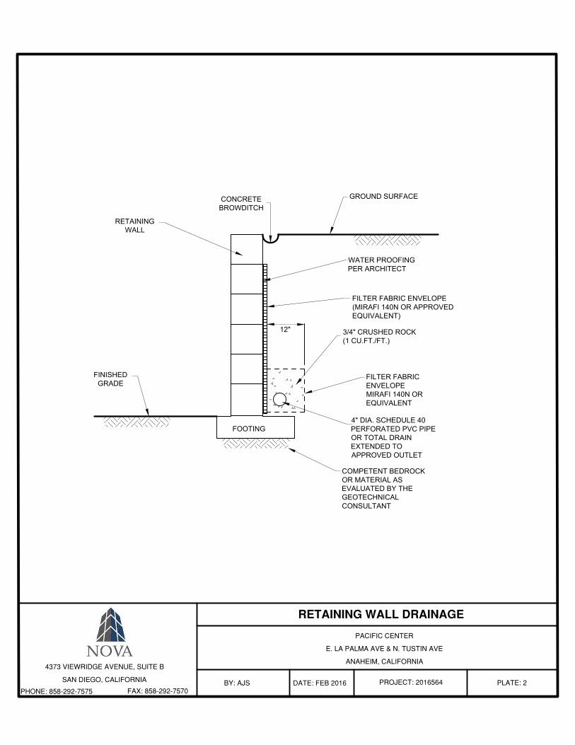
FOOTING
CONCRETE
BROWDITCH
GROUND SURFACE
12"
WATER PROOFING
PER ARCHITECT
FILTER FABRIC ENVELOPE
(MIRAFI 140N OR APPROVED
EQUIVALENT)
3/4" CRUSHED ROCK
(1 CU.FT./FT.)
FILTER FABRIC
ENVELOPE
MIRAFI 140N OR
EQUIVALENT
4" DIA. SCHEDULE 40
PERFORATED PVC PIPE
OR TOTAL DRAIN
EXTENDED TO
APPROVED OUTLET
FINISHED
GRADE
RETAINING
WALL
COMPETENT BEDROCK
OR MATERIAL AS
EVALUATED BY THE
GEOTECHNICAL
CONSULTANT
PACIFIC CENTER
E. LA PALMA AVE & N. TUSTIN AVE
ANAHEIM, CALIFORNIA
DATE: FEB 2016 PROJECT: 2016564 PLATE: 2BY: AJS
4373 VIEWRIDGE AVENUE, SUITE B
SAN DIEGO, CALIFORNIA
PHONE: 858-292-7575 FAX: 858-292-7570

Report of Preliminary Geotechnical Investigation 17 February 2017 Hines Pacific Center, Anaheim, CA NOVA Project No. 2016564
APPENDIX A
USE OF THE GEOTECHNICAL REPORT

Report of Preliminary Geotechnical Investigation 17 February 2017 Hines Pacific Center, Anaheim, CA NOVA Project No. 2016564
APPENDIX B
LOGS OF ENGINEERING BORINGS

PACIFIC CENTER
E LA PALMA AVE & N TUSTIN AVE
ANAHEIM, CALIFORNIA
APPENDIX B-1
D
EP
TH
(F
T)
5
10
15
20
25
30
0
PROJECT NO.: 2016564
LOGGED BY: HE
SO
IL C
LAS
S.
(US
CS
)
BLO
WS
PE
R 1
2-IN
CH
ES
REVIEWED BY: HP
DATE: FEB 2017
JANUARY 7, 2017
8 INCH DIAMETER AUGER BORING
GROUNDWATER NOT ENCOUNTERED
GROUNDWATER
BULK SAMPLE
SPT SAMPLE ( ASTM D1586)
CAL. MOD. SAMPLE (ASTM D3550)
ERONEOUS BLOWCOUNT
NO SAMPLE RECOVERY
GEOLOGIC CONTACT
SOIL TYPE CHANGE
#
*
DIRECT SHEAREXPANSION INDEX
ATTERBERG LIMITSSIEVE ANALYSIS
RESISTANCE VALUECONSOLIDATION
SAND EQUIVALENT
CORROSIVITYMAXIMUM DENSITY
19
SM-ML
GR
AP
HIC
LO
G
REMARKSBU
LK S
AM
PLE
LAB
OR
AT
OR
Y
CA
L/S
PT
SA
MP
LE
MCDSEIALSARVCNSE
CRCME 95
12
13
26
17
14
SM
SP-SM
*SW
N/A
SA
SA
SA
SA
DS
237.0'

PACIFIC CENTER
E LA PALMA AVE & N TUSTIN AVE
ANAHEIM, CALIFORNIA
APPENDIX B-2
D
EP
TH
(F
T)
PROJECT NO.: 2016564
LOGGED BY: HE
SO
IL C
LAS
S.
(US
CS
)
BLO
WS
PE
R 1
2-IN
CH
ES
REVIEWED BY: HP
DATE: FEB 2017
JANUARY 7, 2017
8 INCH DIAMETER AUGER BORING
GROUNDWATER NOT ENCOUNTERED
5
10
15
20
25
30
0
GROUNDWATER
BULK SAMPLE
SPT SAMPLE ( ASTM D1586)
CAL. MOD. SAMPLE (ASTM D3550)
ERONEOUS BLOWCOUNT
NO SAMPLE RECOVERY
GEOLOGIC CONTACT
SOIL TYPE CHANGE
#
*
DIRECT SHEAREXPANSION INDEX
ATTERBERG LIMITSSIEVE ANALYSIS
RESISTANCE VALUECONSOLIDATION
SAND EQUIVALENT
CORROSIVITYMAXIMUM DENSITY
24
SM-ML
GR
AP
HIC
LO
G
REMARKSBU
LK S
AM
PLE
LAB
OR
AT
OR
Y
CA
L/S
PT
SA
MP
LE
MCDSEIALSARVCNSE
CRCME 95
34
17
19
69
19
21
SM-ML
SP
11
SP-SM
SW
SA
SA
SA
N/A
237.0'
MC

PACIFIC CENTER
E LA PALMA AVE & N TUSTIN AVE
ANAHEIM, CALIFORNIA
APPENDIX B-2.2
D
EP
TH
(F
T)
PROJECT NO.: 2016564
LOGGED BY: HE
SO
IL C
LAS
S.
(US
CS
)
BLO
WS
PE
R 1
2-IN
CH
ES
REVIEWED BY: HP
DATE: FEB 2017
JANUARY 7, 2017
8 INCH DIAMETER AUGER BORING
GROUNDWATER NOT ENCOUNTERED
35
40
45
50
55
60
30
GROUNDWATER
BULK SAMPLE
SPT SAMPLE ( ASTM D1586)
CAL. MOD. SAMPLE (ASTM D3550)
ERONEOUS BLOWCOUNT
NO SAMPLE RECOVERY
GEOLOGIC CONTACT
SOIL TYPE CHANGE
#
*
DIRECT SHEAREXPANSION INDEX
ATTERBERG LIMITSSIEVE ANALYSIS
RESISTANCE VALUECONSOLIDATION
SAND EQUIVALENT
CORROSIVITYMAXIMUM DENSITY
27
GR
AP
HIC
LO
G
REMARKSBU
LK S
AM
PLE
LAB
OR
AT
OR
Y
CA
L/S
PT
SA
MP
LE
MCDSEIALSARVCNSE
CRCME 95
28
29
36
SP-SM
N/A
237.0'

PACIFIC CENTER
E LA PALMA AVE & N TUSTIN AVE
ANAHEIM, CALIFORNIA
APPENDIX B-3
D
EP
TH
(F
T)
PROJECT NO.: 2016564
LOGGED BY: HE
SO
IL C
LAS
S.
(US
CS
)
BLO
WS
PE
R 1
2-IN
CH
ES
REVIEWED BY: HP
DATE: FEB 2017
JANUARY 7, 2017
8 INCH DIAMETER AUGER BORING
GROUNDWATER NOT ENCOUNTERED
5
10
15
20
25
30
0
GROUNDWATER
BULK SAMPLE
SPT SAMPLE ( ASTM D1586)
CAL. MOD. SAMPLE (ASTM D3550)
ERONEOUS BLOWCOUNT
NO SAMPLE RECOVERY
GEOLOGIC CONTACT
SOIL TYPE CHANGE
#
*
DIRECT SHEAREXPANSION INDEX
ATTERBERG LIMITSSIEVE ANALYSIS
RESISTANCE VALUECONSOLIDATION
SAND EQUIVALENT
CORROSIVITYMAXIMUM DENSITY
10
SP
GR
AP
HIC
LO
G
REMARKSBU
LK S
AM
PLE
LAB
OR
AT
OR
Y
CA
L/S
PT
SA
MP
LE
MCDSEIALSARVCNSE
CRCME 95
11
15
16
44
12
17
ML
20
SP
SW
SA
SA
SA
SA
SA
SA
SA
SM
SW
SW
SP-SM
MC
N/A
236.0'
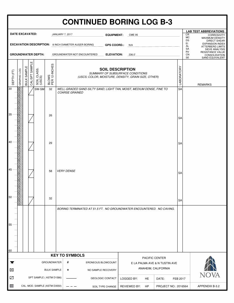
PACIFIC CENTER
E LA PALMA AVE & N TUSTIN AVE
ANAHEIM, CALIFORNIA
APPENDIX B-3.2
D
EP
TH
(F
T)
PROJECT NO.: 2016564
LOGGED BY: HE
SO
IL C
LAS
S.
(US
CS
)
BLO
WS
PE
R 1
2-IN
CH
ES
REVIEWED BY: HP
DATE: FEB 2017
JANUARY 7, 2017
8 INCH DIAMETER AUGER BORING
GROUNDWATER NOT ENCOUNTERED
35
40
45
50
55
60
30
GROUNDWATER
BULK SAMPLE
SPT SAMPLE ( ASTM D1586)
CAL. MOD. SAMPLE (ASTM D3550)
ERONEOUS BLOWCOUNT
NO SAMPLE RECOVERY
GEOLOGIC CONTACT
SOIL TYPE CHANGE
#
*
DIRECT SHEAREXPANSION INDEX
ATTERBERG LIMITSSIEVE ANALYSIS
RESISTANCE VALUECONSOLIDATION
SAND EQUIVALENT
CORROSIVITYMAXIMUM DENSITY
32
GR
AP
HIC
LO
G
REMARKSBU
LK S
AM
PLE
LAB
OR
AT
OR
Y
CA
L/S
PT
SA
MP
LE
MCDSEIALSARVCNSE
CRCME 95
26
29
32
SW-SM
58
SA
SA
SA
SA
SA
N/A
236.0'
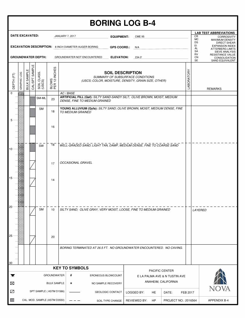
PACIFIC CENTER
E LA PALMA AVE & N TUSTIN AVE
ANAHEIM, CALIFORNIA
APPENDIX B-4
D
EP
TH
(F
T)
PROJECT NO.: 2016564
LOGGED BY: HE
SO
IL C
LAS
S.
(US
CS
)
BLO
WS
PE
R 1
2-IN
CH
ES
REVIEWED BY: HP
DATE: FEB 2017
JANUARY 7, 2017
8 INCH DIAMETER AUGER BORING
GROUNDWATER NOT ENCOUNTERED
5
10
15
20
25
30
0
GROUNDWATER
BULK SAMPLE
SPT SAMPLE ( ASTM D1586)
CAL. MOD. SAMPLE (ASTM D3550)
ERONEOUS BLOWCOUNT
NO SAMPLE RECOVERY
GEOLOGIC CONTACT
SOIL TYPE CHANGE
#
*
DIRECT SHEAREXPANSION INDEX
ATTERBERG LIMITSSIEVE ANALYSIS
RESISTANCE VALUECONSOLIDATION
SAND EQUIVALENT
CORROSIVITYMAXIMUM DENSITY
23
GR
AP
HIC
LO
G
REMARKSBU
LK S
AM
PLE
LAB
OR
AT
OR
Y
CA
L/S
PT
SA
MP
LE
MCDSEIALSARVCNSE
CRCME 95
18
16
18
17
14
10
SM-ML
SM
20
SM
SW
N/A
234.0'

PACIFIC CENTER
E LA PALMA AVE & N TUSTIN AVE
ANAHEIM, CALIFORNIA
APPENDIX B-5
D
EP
TH
(F
T)
PROJECT NO.: 2016564
LOGGED BY: HE
SO
IL C
LAS
S.
(US
CS
)
BLO
WS
PE
R 1
2-IN
CH
ES
REVIEWED BY: HP
DATE: FEB 2017
JANUARY 7, 2017
8 INCH DIAMETER AUGER BORING
GROUNDWATER NOT ENCOUNTERED
5
10
15
20
25
30
0
GROUNDWATER
BULK SAMPLE
SPT SAMPLE ( ASTM D1586)
CAL. MOD. SAMPLE (ASTM D3550)
ERONEOUS BLOWCOUNT
NO SAMPLE RECOVERY
GEOLOGIC CONTACT
SOIL TYPE CHANGE
#
*
DIRECT SHEAREXPANSION INDEX
ATTERBERG LIMITSSIEVE ANALYSIS
RESISTANCE VALUECONSOLIDATION
SAND EQUIVALENT
CORROSIVITYMAXIMUM DENSITY
21
ML
GR
AP
HIC
LO
G
REMARKSBU
LK S
AM
PLE
LAB
OR
AT
OR
Y
CA
L/S
PT
SA
MP
LE
MCDSEIALSARVCNSE
CRCME 95
26
14
28
23
15
13
SM-ML
SW
18
*
SM
SA
SA
SA
N/A
235.0'
SM CR

PACIFIC CENTER
E LA PALMA AVE & N TUSTIN AVE
ANAHEIM, CALIFORNIA
APPENDIX B-6
D
EP
TH
(F
T)
PROJECT NO.: 2016564
LOGGED BY: HE
SO
IL C
LAS
S.
(US
CS
)
BLO
WS
PE
R 1
2-IN
CH
ES
REVIEWED BY: AJS
DATE: FEB 2017
JANUARY 14, 2017
6 INCH DIAMETER HAND AUGER BORING
GROUNDWATER NOT ENCOUNTERED
5
10
15
20
25
30
0
GROUNDWATER
BULK SAMPLE
SPT SAMPLE ( ASTM D1586)
CAL. MOD. SAMPLE (ASTM D3550)
ERONEOUS BLOWCOUNT
NO SAMPLE RECOVERY
GEOLOGIC CONTACT
SOIL TYPE CHANGE
#
*
DIRECT SHEAREXPANSION INDEX
ATTERBERG LIMITSSIEVE ANALYSIS
RESISTANCE VALUECONSOLIDATION
SAND EQUIVALENT
CORROSIVITYMAXIMUM DENSITY
SP
GR
AP
HIC
LO
G
REMARKSBU
LK S
AM
PLE
LAB
OR
AT
OR
Y
CA
L/S
PT
SA
MP
LE
MCDSEIALSARVCNSE
CRHAND AUGER
SM-ML
N/A
233.0'

PACIFIC CENTER
E LA PALMA AVE & N TUSTIN AVE
ANAHEIM, CALIFORNIA
APPENDIX P-1
D
EP
TH
(F
T)
PROJECT NO.: 2016564
LOGGED BY: HE
SO
IL C
LAS
S.
(US
CS
)
BLO
WS
PE
R 1
2-IN
CH
ES
REVIEWED BY: AJS
DATE: FEB 2017
JANUARY 14, 2017
8 INCH DIAMETER AUGER BORING
GROUNDWATER NOT ENCOUNTERED
5
10
15
20
25
30
0
GROUNDWATER
BULK SAMPLE
SPT SAMPLE ( ASTM D1586)
CAL. MOD. SAMPLE (ASTM D3550)
ERONEOUS BLOWCOUNT
NO SAMPLE RECOVERY
GEOLOGIC CONTACT
SOIL TYPE CHANGE
#
*
DIRECT SHEAREXPANSION INDEX
ATTERBERG LIMITSSIEVE ANALYSIS
RESISTANCE VALUECONSOLIDATION
SAND EQUIVALENT
CORROSIVITYMAXIMUM DENSITY
33
GR
AP
HIC
LO
G
REMARKSBU
LK S
AM
PLE
LAB
OR
AT
OR
Y
CA
L/S
PT
SA
MP
LE
MCDSEIALSARVCNSE
CRCME 95
29
SM-ML
N/A
237.0'
SM-ML
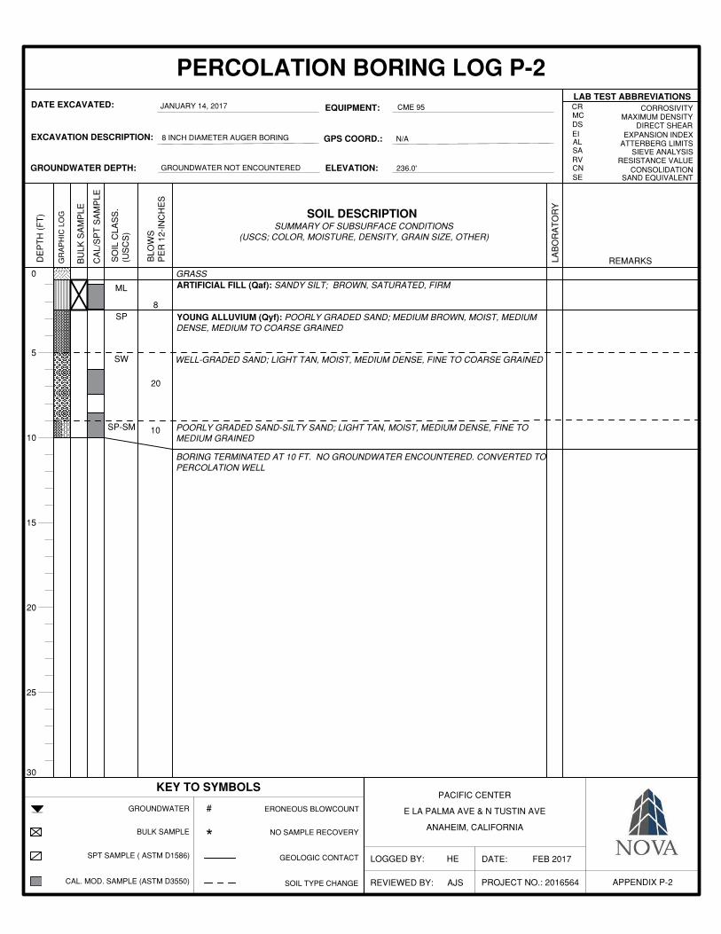
PACIFIC CENTER
E LA PALMA AVE & N TUSTIN AVE
ANAHEIM, CALIFORNIA
APPENDIX P-2
D
EP
TH
(F
T)
PROJECT NO.: 2016564
LOGGED BY: HE
SO
IL C
LAS
S.
(US
CS
)
BLO
WS
PE
R 1
2-IN
CH
ES
REVIEWED BY: AJS
DATE: FEB 2017
JANUARY 14, 2017
8 INCH DIAMETER AUGER BORING
GROUNDWATER NOT ENCOUNTERED
5
10
15
20
25
30
0
GROUNDWATER
BULK SAMPLE
SPT SAMPLE ( ASTM D1586)
CAL. MOD. SAMPLE (ASTM D3550)
ERONEOUS BLOWCOUNT
NO SAMPLE RECOVERY
GEOLOGIC CONTACT
SOIL TYPE CHANGE
#
*
DIRECT SHEAREXPANSION INDEX
ATTERBERG LIMITSSIEVE ANALYSIS
RESISTANCE VALUECONSOLIDATION
SAND EQUIVALENT
CORROSIVITYMAXIMUM DENSITY
8SP
GR
AP
HIC
LO
G
REMARKSBU
LK S
AM
PLE
LAB
OR
AT
OR
Y
CA
L/S
PT
SA
MP
LE
MCDSEIALSARVCNSE
CRCME 95
20
ML
10
SW
SP-SM
N/A
236.0'

PACIFIC CENTER
E LA PALMA AVE & N TUSTIN AVE
ANAHEIM, CALIFORNIA
APPENDIX P-3
D
EP
TH
(F
T)
PROJECT NO.: 2016564
LOGGED BY: HE
SO
IL C
LAS
S.
(US
CS
)
BLO
WS
PE
R 1
2-IN
CH
ES
REVIEWED BY: AJS
DATE: FEB 2017
JANUARY 14, 2017
8 INCH DIAMETER AUGER BORING
GROUNDWATER NOT ENCOUNTERED
5
10
15
20
25
30
0
GROUNDWATER
BULK SAMPLE
SPT SAMPLE ( ASTM D1586)
CAL. MOD. SAMPLE (ASTM D3550)
ERONEOUS BLOWCOUNT
NO SAMPLE RECOVERY
GEOLOGIC CONTACT
SOIL TYPE CHANGE
#
*
DIRECT SHEAREXPANSION INDEX
ATTERBERG LIMITSSIEVE ANALYSIS
RESISTANCE VALUECONSOLIDATION
SAND EQUIVALENT
CORROSIVITYMAXIMUM DENSITY
8
GR
AP
HIC
LO
G
REMARKSBU
LK S
AM
PLE
LAB
OR
AT
OR
Y
CA
L/S
PT
SA
MP
LE
MCDSEIALSARVCNSE
CRCME 95
13
SM-ML
29
ML
16
*
SM
N/A
235.0'
SW
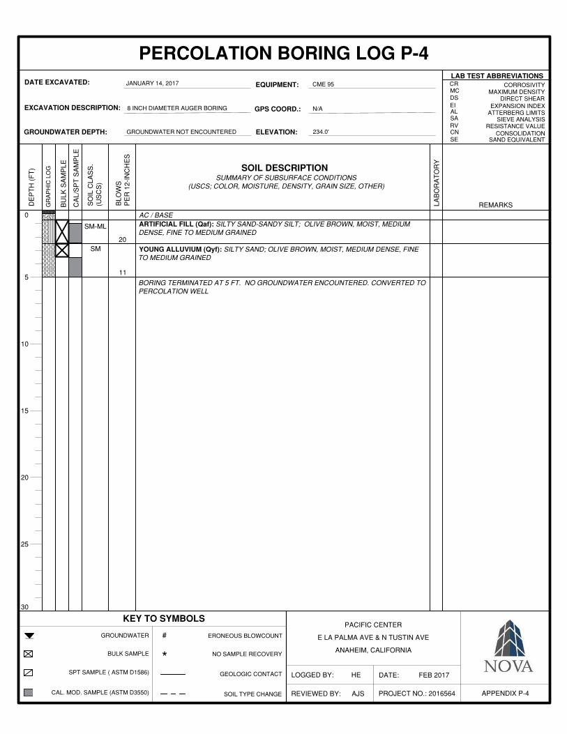
PACIFIC CENTER
E LA PALMA AVE & N TUSTIN AVE
ANAHEIM, CALIFORNIA
APPENDIX P-4
D
EP
TH
(F
T)
PROJECT NO.: 2016564
LOGGED BY: HE
SO
IL C
LAS
S.
(US
CS
)
BLO
WS
PE
R 1
2-IN
CH
ES
REVIEWED BY: AJS
DATE: FEB 2017
JANUARY 14, 2017
8 INCH DIAMETER AUGER BORING
GROUNDWATER NOT ENCOUNTERED
5
10
15
20
25
30
0
GROUNDWATER
BULK SAMPLE
SPT SAMPLE ( ASTM D1586)
CAL. MOD. SAMPLE (ASTM D3550)
ERONEOUS BLOWCOUNT
NO SAMPLE RECOVERY
GEOLOGIC CONTACT
SOIL TYPE CHANGE
#
*
DIRECT SHEAREXPANSION INDEX
ATTERBERG LIMITSSIEVE ANALYSIS
RESISTANCE VALUECONSOLIDATION
SAND EQUIVALENT
CORROSIVITYMAXIMUM DENSITY
20SM
GR
AP
HIC
LO
G
REMARKSBU
LK S
AM
PLE
LAB
OR
AT
OR
Y
CA
L/S
PT
SA
MP
LE
MCDSEIALSARVCNSE
CRCME 95
11
SM-ML
N/A
234.0'
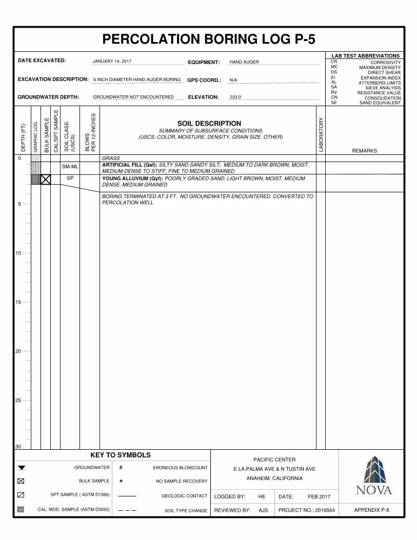
PACIFIC CENTER
E LA PALMA AVE & N TUSTIN AVE
ANAHEIM, CALIFORNIA
APPENDIX P-5
D
EP
TH
(F
T)
PROJECT NO.: 2016564
LOGGED BY: HE
SO
IL C
LAS
S.
(US
CS
)
BLO
WS
PE
R 1
2-IN
CH
ES
REVIEWED BY: AJS
DATE: FEB 2017
JANUARY 14, 2017
6 INCH DIAMETER HAND AUGER BORING
GROUNDWATER NOT ENCOUNTERED
5
10
15
20
25
30
0
GROUNDWATER
BULK SAMPLE
SPT SAMPLE ( ASTM D1586)
CAL. MOD. SAMPLE (ASTM D3550)
ERONEOUS BLOWCOUNT
NO SAMPLE RECOVERY
GEOLOGIC CONTACT
SOIL TYPE CHANGE
#
*
DIRECT SHEAREXPANSION INDEX
ATTERBERG LIMITSSIEVE ANALYSIS
RESISTANCE VALUECONSOLIDATION
SAND EQUIVALENT
CORROSIVITYMAXIMUM DENSITY
SP
GR
AP
HIC
LO
G
REMARKSBU
LK S
AM
PLE
LAB
OR
AT
OR
Y
CA
L/S
PT
SA
MP
LE
MCDSEIALSARVCNSE
CRHAND AUGER
SM-ML
N/A
233.0'

Report of Preliminary Geotechnical Investigation 17 February 2017 Hines Pacific Center, Anaheim, CA NOVA Project No. 2016564
APPENDIX C
LABORATORY ANALYTICAL RESULTS

B-3 @ 6.0'
B-3 @ 9.0'
1/24/2017 LIGHT TAN SAND 2.0 101.4
1/24/2017 97.55.5LIGHT TAN SAND
B-5 @ 1.0' 103.54.7OLIVE BROWN SILTY SAND1/24/2017
B-3 @ 3.0' 1/24/2017 MEDIUM BROWN SAND 7.6 101.6
3
4
5
6
7 1/24/2017
B-5 @ 3.0' 1/24/20178
9
JAN 2017
B-2 @ 1.0' 1/24/2017
B-2 @ 3.0' 1/24/2017
B-3 @ 1.0' 1/24/2017
PROJECT NO.
B-1 @ 1.0'
B-1 @ 9.0'
Soil DescriptionDate
1/24/2017
1/24/2017
Sample Location
2
1
Dry Density (pcf)
Moisture Content (%)
9.0
1.4
120.9
113.1
OLIVE BROWN SILTY SAND
LIGHT BROWN SAND
2.6
OLIVE BROWN SILTY SAND
OLIVE BROWN SILTY SAND
BROWN SILTY SAND
LIGHT TAN SAND
12.5 121.6
10.5 116.3
27.9 93.8
111.0
11.0 105.3
* Note: Soil samples were subject to moisture loss during transportation, prior to reaching NOVA laboratory.
OLIVE BROWN SILTY SAND
B-3 @ 12.0'
MOISTURE-DENSITY TESTPACIFICENTER
E. LA PALMA AVE & N. TUSTIN AVEANAHEIM,CA
DATE2016564

Sample Location: Depth (ft):
USCS Soil Type: Passing No. 200 (%):
PACIFICENTERE. LA PALMA AVE & N. TUSTIN AVE
ANAHEIM, CA
DATE
FineCoarse
JAN 2017
GRADATION ANALYSIS TEST RESULTS
B-19.0'SW5
GRAVEL
PROJECT NO.
2016564
SILT OR CLAY Fine Coarse Medium
SAND
0
10
20
30
40
50
60
70
80
90
100
0.0010.010.1110100
Perc
ent P
assi
ng
Grain Size (mm)
1.5
1 3/4
1/2
3/8
Size (Inches) U.S. Standard Sieve Sizes Hydrometer Analysis
No.
8
No.
16
No.
30
No.
100
No.
200
No.
4
No.
50

Sample Location: Depth (ft):
USCS Soil Type: Passing No. 200 (%):
PACIFICENTERE. LA PALMA AVE & N. TUSTIN AVE
ANAHEIM, CA
DATE
FineCoarse
JAN 2017
GRADATION ANALYSIS TEST RESULTS
B-112.0'SP5
GRAVEL
PROJECT NO.
2016564
SILT OR CLAY Fine Coarse Medium
SAND
0
10
20
30
40
50
60
70
80
90
100
0.0010.010.1110100
Perc
ent P
assi
ng
Grain Size (mm)
1.5
1 3/4
1/2
3/8
Size (Inches) U.S. Standard Sieve Sizes Hydrometer Analysis
No.
8
No.
16
No.
30
No.
100
No.
200
No.
4
No.
50

Sample Location: Depth (ft):
USCS Soil Type: Passing No. 200 (%):
PACIFICENTERE. LA PALMA AVE & N. TUSTIN AVE
ANAHEIM, CA
DATE PROJECT NO.
2016564
SILT OR CLAY Fine Coarse Medium
SAND
FineCoarse
JAN 2017
GRADATION ANALYSIS TEST RESULTS
B-115.0'
SP-SM9
GRAVEL
0
10
20
30
40
50
60
70
80
90
100
0.0010.010.1110100
Perc
ent P
assi
ng
Grain Size (mm)
1.5
1 3/4
1/2
3/8
Size (Inches) U.S. Standard Sieve Sizes Hydrometer Analysis
No.
8
No.
16
No.
30
No.
100
No.
200
No.
4
No.
50

Sample Location: Depth (ft):
USCS Soil Type: Passing No. 200 (%):
PACIFICENTERE. LA PALMA AVE & N. TUSTIN AVE
ANAHEIM, CA
DATE
FineCoarse
JAN 2017
GRADATION ANALYSIS TEST RESULTS
B-120.0'SP5
GRAVEL
PROJECT NO.
2016564
SILT OR CLAY Fine Coarse Medium
SAND
0
10
20
30
40
50
60
70
80
90
100
0.0010.010.1110100
Perc
ent P
assi
ng
Grain Size (mm)
1.5
1 3/4
1/2
3/8
Size (Inches) U.S. Standard Sieve Sizes Hydrometer Analysis
No.
8
No.
16
No.
30
No.
100
No.
200
No.
4
No.
50

Sample Location: Depth (ft):
USCS Soil Type: Passing No. 200 (%):
PACIFICENTERE. LA PALMA AVE & N. TUSTIN AVE
ANAHEIM, CA
DATE
FineCoarse
JAN 2017
GRADATION ANALYSIS TEST RESULTS
B-26.0'SP3
GRAVEL
PROJECT NO.
2016564
SILT OR CLAY Fine Coarse Medium
SAND
0
10
20
30
40
50
60
70
80
90
100
0.0010.010.1110100
Perc
ent P
assi
ng
Grain Size (mm)
1.5
1 3/4
1/2
3/8
Size (Inches) U.S. Standard Sieve Sizes Hydrometer Analysis
No.
8
No.
16
No.
30
No.
100
No.
200
No.
4
No.
50
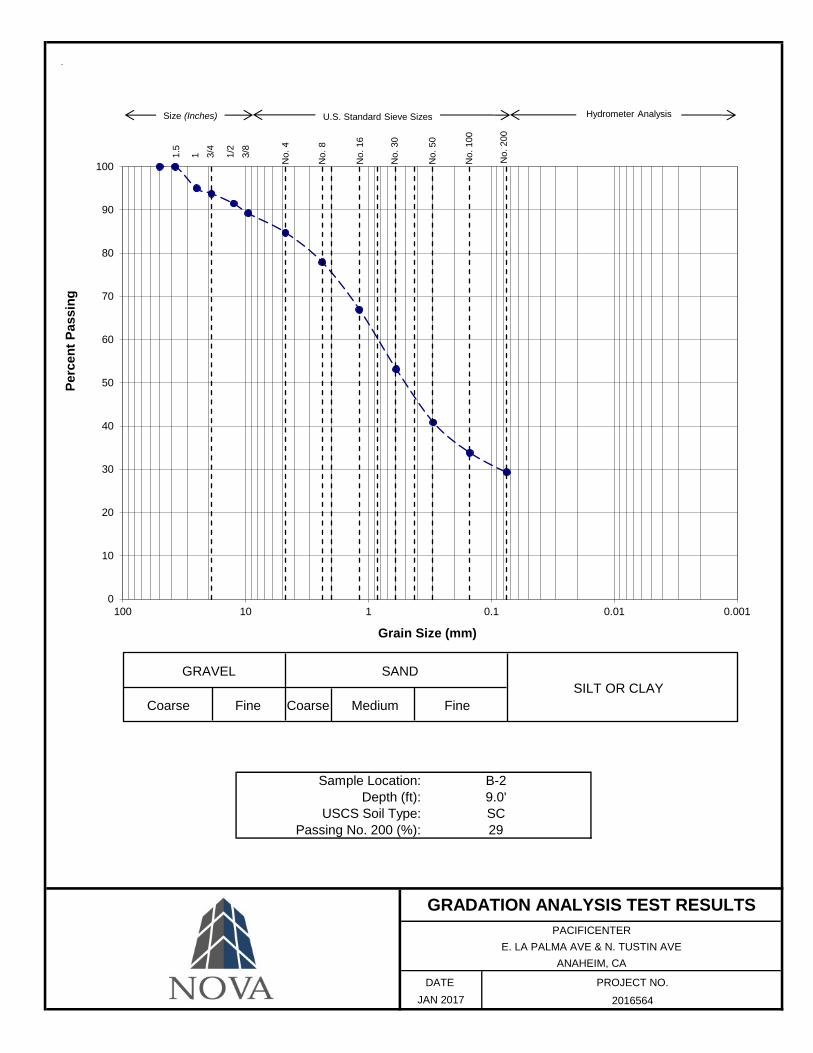
Sample Location: Depth (ft):
USCS Soil Type: Passing No. 200 (%):
PACIFICENTERE. LA PALMA AVE & N. TUSTIN AVE
ANAHEIM, CA
DATE
FineCoarse
JAN 2017
GRADATION ANALYSIS TEST RESULTS
B-29.0'SC29
GRAVEL
PROJECT NO.
2016564
SILT OR CLAY Fine Coarse Medium
SAND
0
10
20
30
40
50
60
70
80
90
100
0.0010.010.1110100
Perc
ent P
assi
ng
Grain Size (mm)
1.5
1 3/4
1/2
3/8
Size (Inches) U.S. Standard Sieve Sizes Hydrometer Analysis
No.
8
No.
16
No.
30
No.
100
No.
200
No.
4
No.
50

Sample Location: Depth (ft):
USCS Soil Type: Passing No. 200 (%):
PACIFICENTERE. LA PALMA AVE & N. TUSTIN AVE
ANAHEIM, CA
DATE PROJECT NO.
2016564
SILT OR CLAY Fine Coarse Medium
SAND
FineCoarse
JAN 2017
GRADATION ANALYSIS TEST RESULTS
B-212.0'GP4
GRAVEL
0
10
20
30
40
50
60
70
80
90
100
0.0010.010.1110100
Perc
ent P
assi
ng
Grain Size (mm)
1.5
1 3/4
1/2
3/8
Size (Inches) U.S. Standard Sieve Sizes Hydrometer Analysis
No.
8
No.
16
No.
30
No.
100
No.
200
No.
4
No.
50

Sample Location: Depth (ft):
USCS Soil Type: Passing No. 200 (%):
PACIFICENTERE. LA PALMA AVE & N. TUSTIN AVE
ANAHEIM, CA
DATE
FineCoarse
JAN 2017
GRADATION ANALYSIS TEST RESULTS
B-215.0'SW5
GRAVEL
PROJECT NO.
2016564
SILT OR CLAY Fine Coarse Medium
SAND
0
10
20
30
40
50
60
70
80
90
100
0.0010.010.1110100
Perc
ent P
assi
ng
Grain Size (mm)
1.5
1 3/4
1/2
3/8
Size (Inches) U.S. Standard Sieve Sizes Hydrometer Analysis
No.
8
No.
16
No.
30
No.
100
No.
200
No.
4
No.
50

Sample Location: Depth (ft):
USCS Soil Type: Passing No. 200 (%):
PACIFICENTERE. LA PALMA AVE & N. TUSTIN AVE
ANAHEIM, CA
DATE
FineCoarse
JAN 2017
GRADATION ANALYSIS TEST RESULTS
B-215.0'
SP-SM7
GRAVEL
PROJECT NO.
2016564
SILT OR CLAY Fine Coarse Medium
SAND
0
10
20
30
40
50
60
70
80
90
100
0.0010.010.1110100
Perc
ent P
assi
ng
Grain Size (mm)
1.5
1 3/4
1/2
3/8
Size (Inches) U.S. Standard Sieve Sizes Hydrometer Analysis
No.
8
No.
16
No.
30
No.
100
No.
200
No.
4
No.
50

Sample Location: Depth (ft):
USCS Soil Type: Passing No. 200 (%):
PACIFICENTERE. LA PALMA AVE & N. TUSTIN AVE
ANAHEIM, CA
DATE
FineCoarse
JAN 2017
GRADATION ANALYSIS TEST RESULTS
B-36.0'SW3
GRAVEL
PROJECT NO.
2016564
SILT OR CLAY Fine Coarse Medium
SAND
0
10
20
30
40
50
60
70
80
90
100
0.0010.010.1110100
Perc
ent P
assi
ng
Grain Size (mm)
1.5
1 3/4
1/2
3/8
Size (Inches) U.S. Standard Sieve Sizes Hydrometer Analysis
No.
8
No.
16
No.
30
No.
100
No.
200
No.
4
No.
50

Sample Location: Depth (ft):
USCS Soil Type: Passing No. 200 (%):
PACIFICENTERE. LA PALMA AVE & N. TUSTIN AVE
ANAHEIM, CA
DATE
FineCoarse
JAN 2017
GRADATION ANALYSIS TEST RESULTS
B-39.0'
SW-SM10
GRAVEL
PROJECT NO.
2016564
SILT OR CLAY Fine Coarse Medium
SAND
0
10
20
30
40
50
60
70
80
90
100
0.0010.010.1110100
Perc
ent P
assi
ng
Grain Size (mm)
1.5
1 3/4
1/2
3/8
Size (Inches) U.S. Standard Sieve Sizes Hydrometer Analysis
No.
8
No.
16
No.
30
No.
100
No.
200
No.
4
No.
50

Sample Location: Depth (ft):
USCS Soil Type: Passing No. 200 (%):
PACIFICENTERE. LA PALMA AVE & N. TUSTIN AVE
ANAHEIM, CA
DATE
FineCoarse
JAN 2017
GRADATION ANALYSIS TEST RESULTS
B-312.0'SW6
GRAVEL
PROJECT NO.
2016564
SILT OR CLAY Fine Coarse Medium
SAND
0
10
20
30
40
50
60
70
80
90
100
0.0010.010.1110100
Perc
ent P
assi
ng
Grain Size (mm)
1.5
1 3/4
1/2
3/8
Size (Inches) U.S. Standard Sieve Sizes Hydrometer Analysis
No.
8
No.
16
No.
30
No.
100
No.
200
No.
4
No.
50

Sample Location: Depth (ft):
USCS Soil Type: Passing No. 200 (%):
PACIFICENTERE. LA PALMA AVE & N. TUSTIN AVE
ANAHEIM, CA
DATE
FineCoarse
JAN 2017
GRADATION ANALYSIS TEST RESULTS
B-315.0'SM21
GRAVEL
PROJECT NO.
2016564
SILT OR CLAY Fine Coarse Medium
SAND
0
10
20
30
40
50
60
70
80
90
100
0.0010.010.1110100
Perc
ent P
assi
ng
Grain Size (mm)
1.5
1 3/4
1/2
3/8
Size (Inches) U.S. Standard Sieve Sizes Hydrometer Analysis
No.
8
No.
16
No.
30
No.
100
No.
200
No.
4
No.
50

Sample Location: Depth (ft):
USCS Soil Type: Passing No. 200 (%):
PACIFICENTERE. LA PALMA AVE & N. TUSTIN AVE
ANAHEIM, CA
DATE
FineCoarse
JAN 2017
GRADATION ANALYSIS TEST RESULTS
B-320.0'SW3
GRAVEL
PROJECT NO.
2016564
SILT OR CLAY Fine Coarse Medium
SAND
0
10
20
30
40
50
60
70
80
90
100
0.0010.010.1110100
Perc
ent P
assi
ng
Grain Size (mm)
1.5
1 3/4
1/2
3/8
Size (Inches) U.S. Standard Sieve Sizes Hydrometer Analysis
No.
8
No.
16
No.
30
No.
100
No.
200
No.
4
No.
50
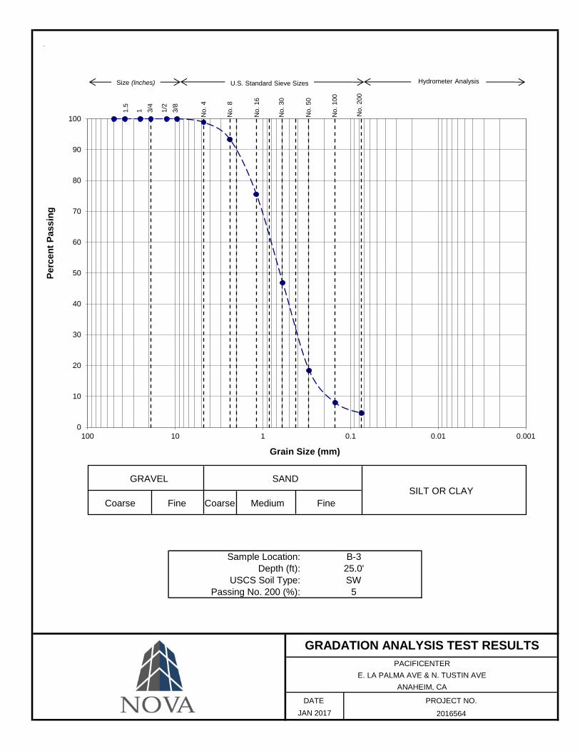
Sample Location: Depth (ft):
USCS Soil Type: Passing No. 200 (%):
PACIFICENTERE. LA PALMA AVE & N. TUSTIN AVE
ANAHEIM, CA
DATE
FineCoarse
JAN 2017
GRADATION ANALYSIS TEST RESULTS
B-325.0'SW5
GRAVEL
PROJECT NO.
2016564
SILT OR CLAY Fine Coarse Medium
SAND
0
10
20
30
40
50
60
70
80
90
100
0.0010.010.1110100
Perc
ent P
assi
ng
Grain Size (mm)
1.5
1 3/4
1/2
3/8
Size (Inches) U.S. Standard Sieve Sizes Hydrometer Analysis
No.
8
No.
16
No.
30
No.
100
No.
200
No.
4
No.
50

Sample Location: Depth (ft):
USCS Soil Type: Passing No. 200 (%):
PACIFICENTERE. LA PALMA AVE & N. TUSTIN AVE
ANAHEIM, CA
DATE
FineCoarse
JAN 2017
GRADATION ANALYSIS TEST RESULTS
B-330.0'
SW-SM12
GRAVEL
PROJECT NO.
2016564
SILT OR CLAY Fine Coarse Medium
SAND
0
10
20
30
40
50
60
70
80
90
100
0.0010.010.1110100
Perc
ent P
assi
ng
Grain Size (mm)
1.5
1 3/4
1/2
3/8
Size (Inches) U.S. Standard Sieve Sizes Hydrometer Analysis
No.
8
No.
16
No.
30
No.
100
No.
200
No.
4
No.
50

Sample Location: Depth (ft):
USCS Soil Type: Passing No. 200 (%):
PACIFICENTERE. LA PALMA AVE & N. TUSTIN AVE
ANAHEIM, CA
DATE
FineCoarse
JAN 2017
GRADATION ANALYSIS TEST RESULTS
B-335.0'
SW-SM9
GRAVEL
PROJECT NO.
2016564
SILT OR CLAY Fine Coarse Medium
SAND
0
10
20
30
40
50
60
70
80
90
100
0.0010.010.1110100
Perc
ent P
assi
ng
Grain Size (mm)
1.5
1 3/4
1/2
3/8
Size (Inches) U.S. Standard Sieve Sizes Hydrometer Analysis
No.
8
No.
16
No.
30
No.
100
No.
200
No.
4
No.
50

Sample Location: Depth (ft):
USCS Soil Type: Passing No. 200 (%):
PACIFICENTERE. LA PALMA AVE & N. TUSTIN AVE
ANAHEIM, CA
DATE
FineCoarse
JAN 2017
GRADATION ANALYSIS TEST RESULTS
B-340.0'
SW-SM8
GRAVEL
PROJECT NO.
2016564
SILT OR CLAY Fine Coarse Medium
SAND
0
10
20
30
40
50
60
70
80
90
100
0.0010.010.1110100
Perc
ent P
assi
ng
Grain Size (mm)
1.5
1 3/4
1/2
3/8
Size (Inches) U.S. Standard Sieve Sizes Hydrometer Analysis
No.
8
No.
16
No.
30
No.
100
No.
200
No.
4
No.
50

Sample Location: Depth (ft):
USCS Soil Type: Passing No. 200 (%):
PACIFICENTERE. LA PALMA AVE & N. TUSTIN AVE
ANAHEIM, CA
DATE
FineCoarse
JAN 2017
GRADATION ANALYSIS TEST RESULTS
B-350.0'
SW-SM8
GRAVEL
PROJECT NO.
2016564
SILT OR CLAY Fine Coarse Medium
SAND
0
10
20
30
40
50
60
70
80
90
100
0.0010.010.1110100
Perc
ent P
assi
ng
Grain Size (mm)
1.5
1 3/4
1/2
3/8
Size (Inches) U.S. Standard Sieve Sizes Hydrometer Analysis
No.
8
No.
16
No.
30
No.
100
No.
200
No.
4
No.
50
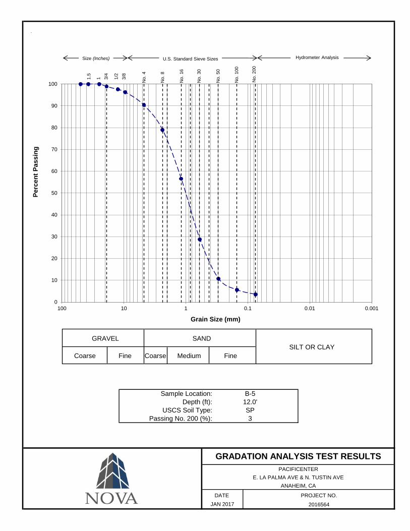
Sample Location: Depth (ft):
USCS Soil Type: Passing No. 200 (%):
PACIFICENTERE. LA PALMA AVE & N. TUSTIN AVE
ANAHEIM, CA
DATE PROJECT NO.
2016564
SILT OR CLAY Fine Coarse Medium
SAND
FineCoarse
JAN 2017
GRADATION ANALYSIS TEST RESULTS
B-512.0'SP3
GRAVEL
0
10
20
30
40
50
60
70
80
90
100
0.0010.010.1110100
Perc
ent P
assi
ng
Grain Size (mm)
1.5
1 3/4
1/2
3/8
Size (Inches) U.S. Standard Sieve Sizes Hydrometer Analysis
No.
8
No.
16
No.
30
No.
100
No.
200
No.
4
No.
50
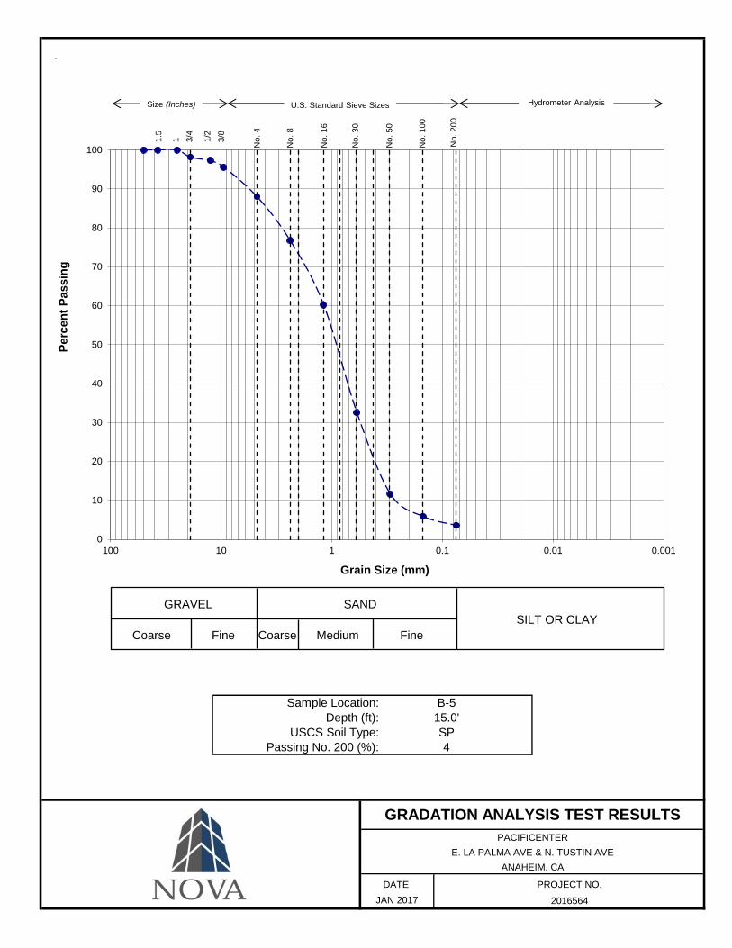
Sample Location: Depth (ft):
USCS Soil Type: Passing No. 200 (%):
PACIFICENTERE. LA PALMA AVE & N. TUSTIN AVE
ANAHEIM, CA
DATE
FineCoarse
JAN 2017
GRADATION ANALYSIS TEST RESULTS
B-515.0'SP4
GRAVEL
PROJECT NO.
2016564
SILT OR CLAY Fine Coarse Medium
SAND
0
10
20
30
40
50
60
70
80
90
100
0.0010.010.1110100
Perc
ent P
assi
ng
Grain Size (mm)
1.5
1 3/4
1/2
3/8
Size (Inches) U.S. Standard Sieve Sizes Hydrometer Analysis
No.
8
No.
16
No.
30
No.
100
No.
200
No.
4
No.
50
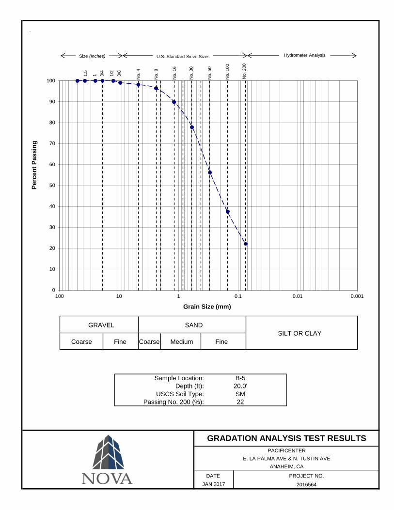
Sample Location: Depth (ft):
USCS Soil Type: Passing No. 200 (%):
PACIFICENTERE. LA PALMA AVE & N. TUSTIN AVE
ANAHEIM, CA
DATE
FineCoarse
JAN 2017
GRADATION ANALYSIS TEST RESULTS
B-520.0'SM22
GRAVEL
PROJECT NO.
2016564
SILT OR CLAY Fine Coarse Medium
SAND
0
10
20
30
40
50
60
70
80
90
100
0.0010.010.1110100
Perc
ent P
assi
ng
Grain Size (mm)
1.5
1 3/4
1/2
3/8
Size (Inches) U.S. Standard Sieve Sizes Hydrometer Analysis
No.
8
No.
16
No.
30
No.
100
No.
200
No.
4
No.
50

PERFORMED IN GENERAL ACCORDANCE WITH: ASTM D 1557 ASTM D 698 METHOD: A B C
PACIFICENTERE. LA PALMA AVE & N. TUSTIN AVE
ANAHEIM,CA
DATE
Soil Description
GRAYISH BROWN SILTY SAND
Dry Density and Moisture Content Values Corrected for Oversize (ASTM D4718)
Maximum Dry Density
(pcf)Sample Location
B-2 @ 1.0'-6.0'
PROCTOR DENSITY TEST RESULTS
JAN 2017
8.6131.3
PROJECT NO.
2016564
Optimum Moisture Content
(%)
100.0
105.0
110.0
115.0
120.0
125.0
130.0
135.0
140.0
145.0
150.0
0.0 5.0 10.0 15.0 20.0
DR
Y D
ENSI
TY (p
cf)
MOISTURE CONTENT (%)
Zero Air Void Line(Specific Gravity = 2.70)
Zero Air Void Line(Specific Gravity = 2.60)
Zero Air Void Line(Specific Gravity = 2.50)

PERFORMED IN GENERAL ACCORDANCE WITH: ASTM D 1557 ASTM D 698 METHOD: A B C
PACIFICENTERE. LA PALMA AVE & N. TUSTIN AVE
ANAHEIM,CA
DATE
PROCTOR DENSITY TEST RESULTS
JAN 2017
9.2129
PROJECT NO.
2016564
Optimum Moisture Content
(%)Soil Description
BROWN SILTY SAND
Dry Density and Moisture Content Values Corrected for Oversize (ASTM D4718)
Maximum Dry Density
(pcf)Sample Location
B-3 @ 1.0'-6.0'
100.0
105.0
110.0
115.0
120.0
125.0
130.0
135.0
140.0
145.0
150.0
0.0 5.0 10.0 15.0 20.0
DR
Y D
ENSI
TY (p
cf)
MOISTURE CONTENT (%)
Zero Air Void Line(Specific Gravity = 2.70)
Zero Air Void Line(Specific Gravity = 2.60)
Zero Air Void Line(Specific Gravity = 2.50)

PACIFICENTERE. LA PALMA AVE & N. TUSTIN AVE
ANAHEIM,CADATE
SAMPLE LOCATION
B-2 SM
R-VALUE TEST RESULTS
SOIL TYPE R-VALUE
58
SAMPLE DEPTH (FT)
1.0' - 6.0'
PROJECT NO.2016564JAN 2017
Report of Preliminary Geotechnical Investigation 17 February 2017 Hines Pacific Center, Anaheim, CA NOVA Project No. 2016564
APPENDIX D
RECORDS OF PERCOLATION / INFILTRATION TESTING

Worksheets from Orange County Technical Guidance Document (12-20-2013 )
See TGD for instructions and/or examples related to these worksheets:
www.ocwatersheds.com/WQMP.aspx

Worksheets from Orange County Technical Guidance Document (12-20-2013) See TGD for instructions and/or examples related to these worksheets
www.ocwatersheds.com/WQMP.aspx
Table 2.7: Infiltration BMP Feasibility Worksheet Infeasibility Criteria Yes No
1
Would Infiltration BMPs pose significant risk for groundwater related concerns? Refer to Appendix VII (Worksheet I) for guidance on groundwater-related infiltration feasibility criteria.
X
Provide basis: The subject site is located in an area where groundwater level is below 15 feet from the surface and was not encountered to the maximum depths explored of 72 feet below surface grade. (Refer to adjunct Geotechnical Investigation). Summarize findings of studies provide reference to studies, calculations, maps, data sources, etc. Provide narrative discussion of study/data source applicability.
2
Would Infiltration BMPs pose significant risk of increasing risk of geotechnical hazards that cannot be mitigated to an acceptable level? (Yes if the answer to any of the following questions is yes, as established by a geotechnical expert): • The BMP can only be located less than 50 feet
away from slopes steeper than 15 percent • The BMP can only be located less than eight feet
from building foundations or an alternative setback. • A study prepared by a geotechnical professional or
an available watershed study substantiates that stormwater infiltration would potentially result in significantly increased risks of geotechnical hazards that cannot be mitigated to an acceptable level.
X
Provide basis: The infiltration BMP’s if properly designed should not negatively affect the project and should not present any new geotechnical hazards.
Summarize findings of studies provide reference to studies, calculations, maps, data sources, etc. Provide narrative discussion of study/data source applicability.
3
Would infiltration of the DCV from drainage area violate downstream water rights?
Provide basis: NOVA did not evaluate downstream water rights. Summarize findings of studies provide reference to studies, calculations, maps, data sources, etc. Provide narrative discussion of study/data source applicability.

Worksheets from Orange County Technical Guidance Document (12-20-2013) See TGD for instructions and/or examples related to these worksheets
www.ocwatersheds.com/WQMP.aspx
Table 2.7: Infiltration BMP Feasibility Worksheet (continued)
Partial Infeasibility Criteria Yes No
4
Is proposed infiltration facility located on HSG D soils or the site geotechnical investigation identifies presence of soil characteristics which support categorization as D soils?
X
Provide basis: Review of the Orange County Technical Guidance Document indicates that the subject site is underlain by Hydrologic Soil Group B.
Summarize findings of studies provide reference to studies, calculations, maps, data sources, etc. Provide narrative discussion of study/data source applicability.
5
Is measured infiltration rate below proposed facility less than 0.3 inches per hour? This calculation shall be based on the methods described in Appendix VII.
X
Provide basis: NOVA's Preliminary Geotechnical Investigation indicates that infiltration rates exceeded more than 0.3 inches per hour. (See adjunct geotechnical report)
Summarize findings of studies provide reference to studies, calculations, maps, data sources, etc. Provide narrative discussion of study/data source applicability.
6
Would reduction of over predeveloped conditions cause impairments to downstream beneficial uses, such as change of seasonality of ephemeral washes or increased discharge of contaminated groundwater to surface waters?
Provide citation to applicable study and summarize findings relative to the amount of infiltration that is permissible: NOVA did not evaluate downstream beneficial uses or groundwater contamination. Summarize findings of studies provide reference to studies, calculations, maps, data sources, etc. Provide narrative discussion of study/data source applicability.
7
Would an increase in infiltration over predeveloped conditions cause impairments to downstream beneficial uses, such as change of seasonality of ephemeral washes or increased discharge of contaminated groundwater to surface waters?
Provide citation to applicable study and summarize findings relative to the amount of infiltration that is permissible: NOVA did not evaluate downstream beneficial uses or groundwater
contamination. Summarize findings of studies provide reference to studies, calculations, maps, data sources, etc. Provide narrative discussion of study/data source applicability.

Worksheets from Orange County Technical Guidance Document (12-20-2013) See TGD for instructions and/or examples related to these worksheets
www.ocwatersheds.com/WQMP.aspx
Table 2.7: Infiltration BMP Feasibility Worksheet (continued)
Infiltration Screening Results (check box corresponding to result):
8
Is there substantial evidence that infiltration from the project would result in a significant increase in I&I to the sanitary sewer that cannot be sufficiently mitigated? (See Appendix XVII) Provide narrative discussion and supporting evidence: NOVA did not evaluate the effect of infiltration on the sanitary sewer system. Summarize findings of studies provide reference to studies, calculations, maps, data sources, etc. Provide narrative discussion of study/data source applicability.
9
If any answer from row 1-3 is yes: infiltration of any volume is not feasible within the DMA or equivalent.
Provide basis:
Summarize findings of infeasibility screening
10
If any answer from row 4-8 is yes, infiltration is permissible but is not presumed to be feasible for the entire DCV. Criteria for designing biotreatment BMPs to achieve the maximum feasible infiltration and ET shall apply.
Provide basis:
Summarize findings of infeasibility screening
11
If all answers to rows 1 through 10 are no, infiltration of the full DCV is potentially feasible, BMPs must be designed to infiltrate the full DCV to the maximum extent practicable.
X

Worksheets from Orange County Technical Guidance Document (12-20-2013) See TGD for instructions and/or examples related to these worksheets
www.ocwatersheds.com/WQMP.aspx
United States Department of Agriculture
Natural Resources Conservation Service