report tesla turbine
DESCRIPTION
Tesla TurbineTRANSCRIPT
MAJOR PROJECT REPORT ON TESLA TURBINE
SHAHEED BHAGAT SINGH STATE TECHNICAL CAMPUS 1
CHAPTER 1
INTRODUCTION
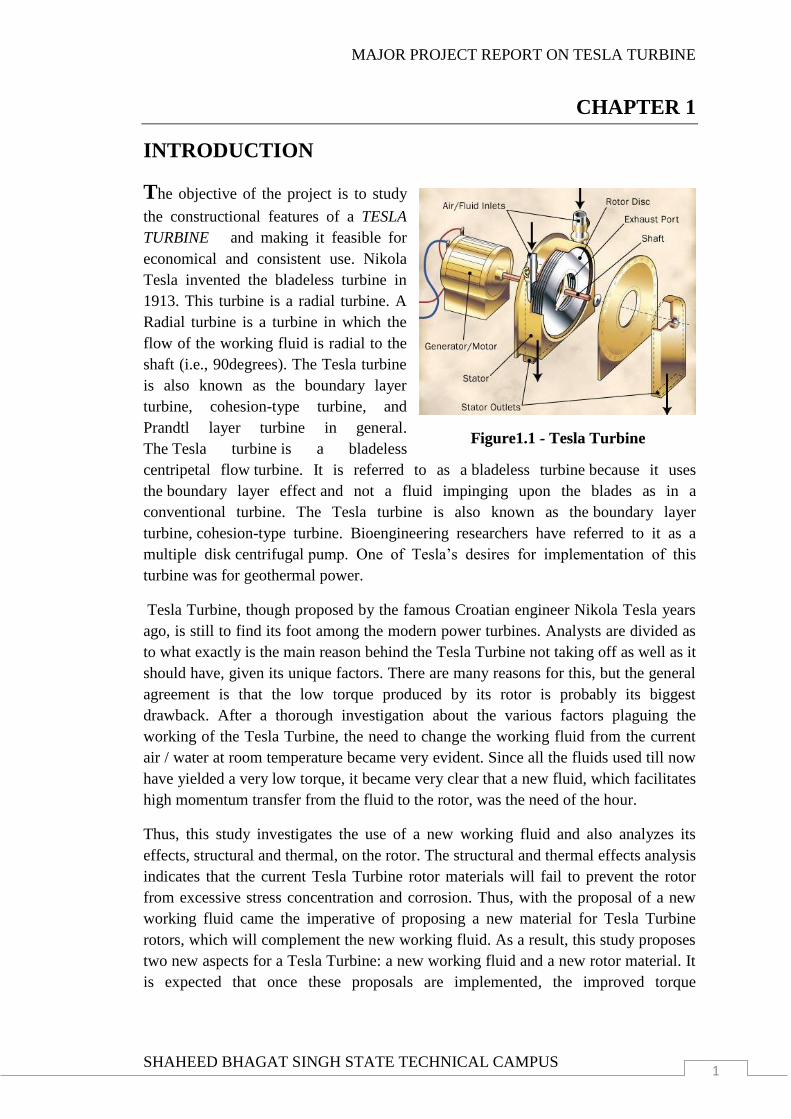
The objective of the project is to study
the constructional features of a TESLA
TURBINE and making it feasible for
economical and consistent use. Nikola
Tesla invented the bladeless turbine in
1913. This turbine is a radial turbine. A
Radial turbine is a turbine in which the
flow of the working fluid is radial to the
shaft (i.e., 90degrees). The Tesla turbine
is also known as the boundary layer
turbine, cohesion-type turbine, and
Prandtl layer turbine in general.
The Tesla turbine is a bladeless
centripetal flow turbine. It is referred to as a bladeless turbine because it uses
the boundary layer effect and not a fluid impinging upon the blades as in a
conventional turbine. The Tesla turbine is also known as the boundary layer
turbine, cohesion-type turbine. Bioengineering researchers have referred to it as a
multiple disk centrifugal pump. One of Tesla‟s desires for implementation of this
turbine was for geothermal power.
Tesla Turbine, though proposed by the famous Croatian engineer Nikola Tesla years
ago, is still to find its foot among the modern power turbines. Analysts are divided as
to what exactly is the main reason behind the Tesla Turbine not taking off as well as it
should have, given its unique factors. There are many reasons for this, but the general
agreement is that the low torque produced by its rotor is probably its biggest
drawback. After a thorough investigation about the various factors plaguing the
working of the Tesla Turbine, the need to change the working fluid from the current
air / water at room temperature became very evident. Since all the fluids used till now
have yielded a very low torque, it became very clear that a new fluid, which facilitates
high momentum transfer from the fluid to the rotor, was the need of the hour.
Thus, this study investigates the use of a new working fluid and also analyzes its
effects, structural and thermal, on the rotor. The structural and thermal effects analysis
indicates that the current Tesla Turbine rotor materials will fail to prevent the rotor
from excessive stress concentration and corrosion. Thus, with the proposal of a new
working fluid came the imperative of proposing a new material for Tesla Turbine
rotors, which will complement the new working fluid. As a result, this study proposes
two new aspects for a Tesla Turbine: a new working fluid and a new rotor material. It
is expected that once these proposals are implemented, the improved torque
Figure1.1 - Tesla Turbine
MAJOR PROJECT REPORT ON TESLA TURBINE
SHAHEED BHAGAT SINGH STATE TECHNICAL CAMPUS 2
generation by the Tesla Turbine will improve its acceptance levels and lead to its
increased popularity.
Moreover talking about the structural analysis of the tesla turbine structural analysis
of the rotor components (turbine blades) have so far been mostly confined to
conventional turbines like steam turbines, gas turbines and wind turbines. These
studies dealt with the structural and dynamic stresses, the crack propagation etc.
experienced in actual working conditions by the turbine blades. Though analyses of
more specialized turbines like aero-engine turbines have been done, Tesla Turbine
analysis papers remain highly elusive.
Very few papers have been written researching Tesla Turbine because of its low level
of commercial adoption. This was designed, tested and analyzed a multiple-disk Tesla
type fan two-dimensionally using the conservation of angular momentum principle.
Their study showed that Tesla Turbines exhibited exceptionally low performance
characteristics, due to the low viscosity, tangential nature of the flow, and large
mechanical energy losses at both suction and discharge sections that are comparable
to the total input power. Their research determined the local and shearing stresses
developed within the rotor as also the power transmitted from the air to the rotor .
From this study, the main reason for low torque, low viscosity of the working fluid,
was identified and this principle played a significant role in the proposal of the new
working fluid later on in this study.
After discussing the relative motion of rotating surfaces, the transport equations
describing the flow between parallel rotating disks are derived, estimating the
boundary layer thickness under laminar and turbulent regimes, leading to expressions
yielding the width between consecutive disks. They have also described the device
behavior acting as an air compressor or water pump. Even they have stated in their
paper that a comprehensive discussion of the fluid mechanics involved in the design
of Tesla Turbine components has never taken place. From their analysis, it became
clear that virtually no consideration was ever given for exploring new materials for
the construction of Tesla Turbine rotors. This huge void had to be filled, but by doing
so, the close relation between the working fluid and the rotor material had to be taken
into account.
Armstrong made a modified Tesla Turbine and analyzed it way back in 1952. But in
those days, the science of composite materials was not advanced enough for him to
explore the use of laminated composite materials as rotor materials. But this study
does exactly that i.e. proposing the new rotor material but within the framework of the
laminar fluid characteristics of the new working fluid proposed.
MAJOR PROJECT REPORT ON TESLA TURBINE
SHAHEED BHAGAT SINGH STATE TECHNICAL CAMPUS 3
1.1 History
A Tesla turbine is a quite unique technology. It was invented and patented by Nikola
Tesla on the 21st October 1909 at the United States Patent Office from experiments
done in England. The US patent 1061206 was granted on the 6th May 1913, although
historical documents suggest that that Tesla first showed a 200 horsepower (about
150kw) 16,000 RPM version on the 10th of July 1906 (on Tesla‟s 50th birthday).
From what Tesla wrote in the patent it seems his experiments were mainly done with
fluids but had confirmed it works with air as well. Tesla had his own personal
requirements for a generator for his laboratory. You have to remember use of
electrical power was still in its infancy which Tesla played a critical role developing
many of the electrical components we now take for granted. Typically Tesla found his
alternative and better way of generating power, using a steam boiler powering a tesla
turbine which in turn powered an AC generator.
Unlike conventional turbines, jet engines and most pumps, Tesla‟s turbine can be
designed to be reversible with no loss in efficiency. Normally compressed air, fluids
or steam is applied to the inlet and the turbine spins giving a mechanic rotational
output. However, it can also double up as a pump, by rotating the shaft the
air/fluid/steam can and be sucked and blown from the inlets / outlets. This makes it
unique in being a reversible turbine and a reversible pump. However efficiency
increases can be made by tailoring the pump to the medium. In other words an air
powered turbine may have some slight design changes compared to water powered
turbine.
Sadly unlike the work done with electricity the Tesla turbine never became popular
and was simply forgotten about. Only in the last few years has there been new
interest. Tesla turbines are also known as cohesion turbines, bladeless turbines,
boundary layer turbines and Prandtl layer turbines.
Interestingly, using the word "turbine" to describe Tesla's invention seems a bit
misleading. That's because most people think of a turbine as a shaft with blades -- like
fan blades -- attached to it. In fact, Webster's dictionary defines a turbine as
an engine turned by the force of gas or water on fan blades. But the Tesla turbine
doesn't have any blades. It has a series of closely packed parallel disks attached to a
shaft and arranged within a sealed chamber. When a fluid is allowed to enter the
chamber and pass between the disks, the disks turn, which in turn rotates the shaft.
This rotary motion can be used in a variety of ways, from powering pumps, blowers
and compressors to running cars and airplanes. In fact, Tesla claimed that the turbine
was the most efficient and the most simply designed rotary engine ever designed.
MAJOR PROJECT REPORT ON TESLA TURBINE
SHAHEED BHAGAT SINGH STATE TECHNICAL CAMPUS 4
CHAPTER 2
CONSTRUCTION
The project mainly concentrates on use of muscular force to compress air which is
used as the working fluid in the turbine. Construction of the project can be categorised
in three parts as following:
1. Turbine
2. Air Compression Unit
3. Storage Unit
4. Power Generation Unit
The above mentioned parts are discussed in detail in the following sections.
2.1 TESLA TURBINE
A Tesla turbine consists of a group of smooth disks held together with spacers in
between them, with nozzles applying a moving fluid tangentially to the disk. The fluid
rotates the disk due to viscosity of the fluid and the adhesion of the surface layer of
the fluid to the disc. Since there are no projections in the rotor, it is very sturdy. All
the plates and washers are interference-fitted on to a shaft provided with bearings at
both ends. This construction allows free expansion and contraction of each plate under
the constantly changing combined effect of heat and centrifugal force. The other
advantages of such an arrangement are higher resultant active plate area and thus
more power, higher efficiency, reduced warping, diminished leakage and reduced
friction losses. The rotor is better suited for dynamic balancing and since surface
friction resists disturbing forces, a quiet running is ensured. Because of this and also
because of the flexibility of the discs, the turbine is insulated from damages which are
usually caused by vibration or turbulence.
2.1.1 Working Principle
When a fluid flows around the outside of a body, it produces a force that tends to drag
the body in the direction of the flow. The drag acting on a moving object such as a
ship or an airplane must be overcome by the propulsion system. Drag takes two
forms, skin friction drag and form drag. Skin friction drag is due to the viscous
shearing that takes place between the surface and the layer of fluid immediately above
it. This occurs on surfaces of objects that are long in the direction of flow compared to
then height. Such bodies are called streamlined. When a fluid flows over a solid
surface, the layer next to the surface may become attached to it (it wets the surface).
This is called the 'no slip condition'. The layers of fluid above the surface are moving
so there must be shearing taking place between the layers of the fluid. The shear stress
acting between the wall and the first moving layer next to it is called the wall shear
stress and denoted τw.
MAJOR PROJECT REPORT ON TESLA TURBINE
SHAHEED BHAGAT SINGH STATE TECHNICAL CAMPUS 5
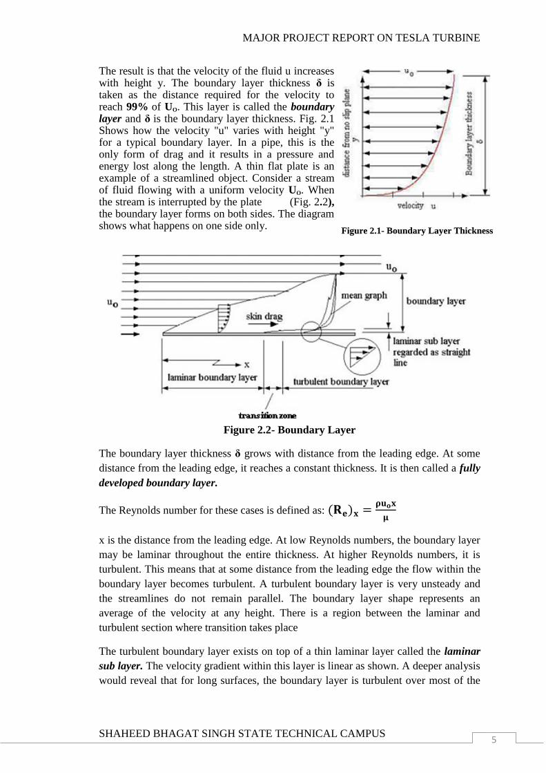
The result is that the velocity of the fluid u increases with height y. The boundary layer thickness δ is taken as the distance required for the velocity to reach 99% of UO. This layer is called the boundary layer and δ is the boundary layer thickness. Fig. 2.1 Shows how the velocity "u" varies with height "y" for a typical boundary layer. In a pipe, this is the only form of drag and it results in a pressure and energy lost along the length. A thin flat plate is an example of a streamlined object. Consider a stream of fluid flowing with a uniform velocity UO. When the stream is interrupted by the plate (Fig. 2.2), the boundary layer forms on both sides. The diagram shows what happens on one side only.
Figure 2.2- Boundary Layer
The boundary layer thickness δ grows with distance from the leading edge. At some
distance from the leading edge, it reaches a constant thickness. It is then called a fully
developed boundary layer.
The Reynolds number for these cases is defined as:
x is the distance from the leading edge. At low Reynolds numbers, the boundary layer
may be laminar throughout the entire thickness. At higher Reynolds numbers, it is
turbulent. This means that at some distance from the leading edge the flow within the
boundary layer becomes turbulent. A turbulent boundary layer is very unsteady and
the streamlines do not remain parallel. The boundary layer shape represents an
average of the velocity at any height. There is a region between the laminar and
turbulent section where transition takes place
The turbulent boundary layer exists on top of a thin laminar layer called the laminar
sub layer. The velocity gradient within this layer is linear as shown. A deeper analysis
would reveal that for long surfaces, the boundary layer is turbulent over most of the
Figure 2.1- Boundary Layer Thickness
MAJOR PROJECT REPORT ON TESLA TURBINE
SHAHEED BHAGAT SINGH STATE TECHNICAL CAMPUS 6
length. Many equations have been developed to describe the shape of the laminar and
turbulent boundary layers and these may be used to estimate the skin friction drag.
Note that for this ideal example, it is assumed that the velocity is the undisturbed
velocity Uo everywhere outside the boundary layer and that there is no acceleration
and hence no change in the static pressure acting on the surface. There is hence no
drag force due to pressure changes.
Calculating Skin Drag
The skin drag is due to the wall shear stress τw and this acts on the surface area
(wetted area). The drag force is hence: R = τw x wetted area. The dynamic pressure is
the pressure resulting from the conversion of the kinetic energy of the stream into
pressure and is defined by the expression
.
The drag coefficient is defined as
Note that this is the same definition for the pipe friction coefficient Cf and it is in fact
the same thing. It is used in the Darcy formula to calculate the pressure lost in pipes
due to friction. For a smooth surface, it can be shown that CDf = 0.074(Re)x-1/5
(Re)x is the Reynolds number based on the length. (Re)x =
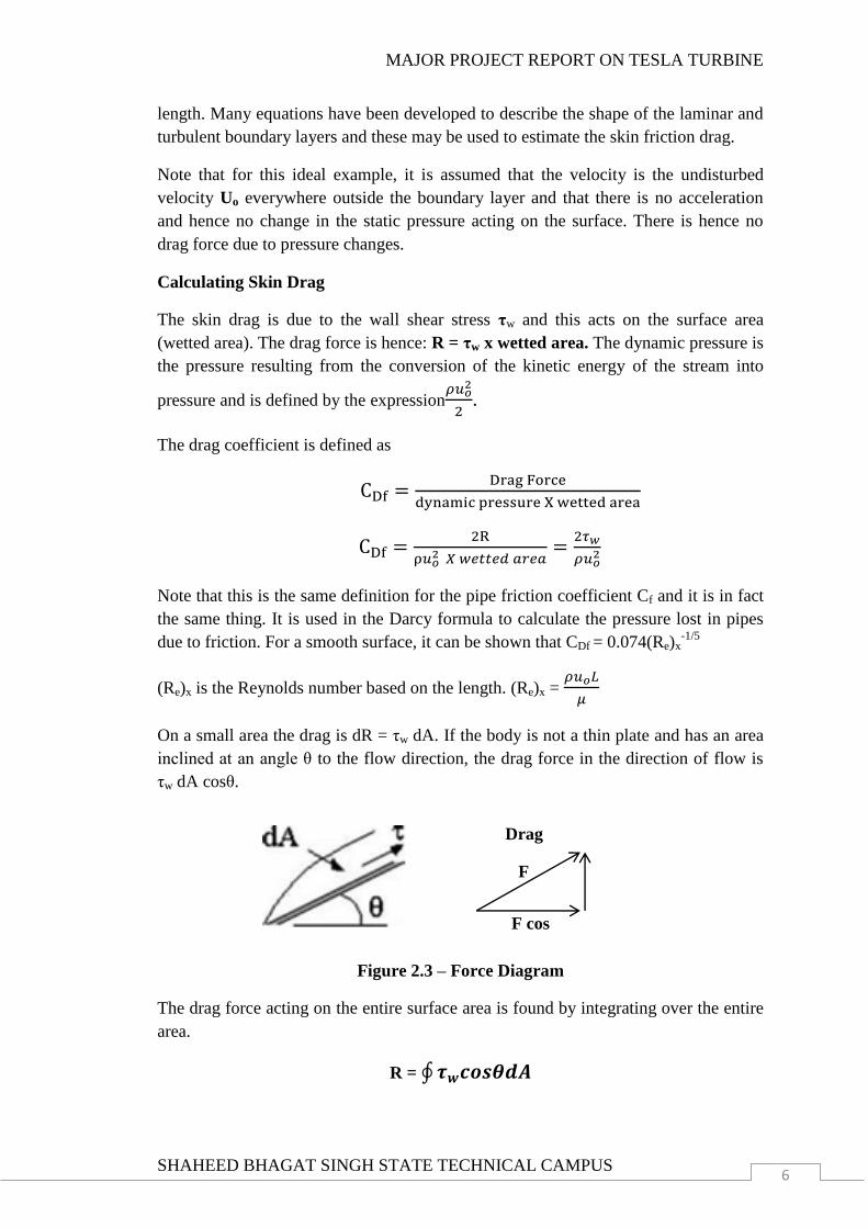
On a small area the drag is dR = τw dA. If the body is not a thin plate and has an area
inclined at an angle θ to the flow direction, the drag force in the direction of flow is
τw dA cosθ.
Figure 2.3 – Force Diagram
The drag force acting on the entire surface area is found by integrating over the entire
area.
R = ∮
F cos
Drag
F

MAJOR PROJECT REPORT ON TESLA TURBINE
SHAHEED BHAGAT SINGH STATE TECHNICAL CAMPUS 7
2.1.2 Construction
Compared to a reciprocating engine, the Tesla turbine is simplicity incarnate. The two
most important parts of the turbine, the rotor and the stator, are explained ahead in
more detail.
Rotor
Unlike the conventional turbine, the Tesla turbine does not have blades and uses a
combination of disks and spacers instead. The diameter and number of the disks can
change depending upon factors concerned with a particular application. Each disk is
provided with openings surrounding the shaft. Between every two discs, there are
metal spacers provided to ensure a gap is maintained between discs, so as to ensure
free flow of fluid. Once a free flow is ensured, space should be provided for the fluid
to exit, and for that, the above mentioned openings are provided. All the discs and
spacers are interference-fitted on the shaft and thus their rotation is transferred to the
shaft. The rotor of the turbine is designed using compact disks and shaft in the center.
The detailed drawing of the designed rotor is provided below.
Figure 2.4 – Turbine Rotor
MAJOR PROJECT REPORT ON TESLA TURBINE
SHAHEED BHAGAT SINGH STATE TECHNICAL CAMPUS 8
Stator
The rotor assembly is enclosed within a square stator, which is the stationary part of
the Tesla turbine. The square shape should be just slightly bigger than the rotor in
order to allow efficient flow of fluid. The stator also has an inlet in the form of a hole.
This is the fundamental design. To rotate the turbine, a high-pressure fluid is passed
through the hole provided at the top. The fluid makes its way through the rotor disks
and causes the rotor to rotate. Finally, the fluid exits from the exhaust ports at the
center of the turbine. The stator of the turbine consists of the following parts:
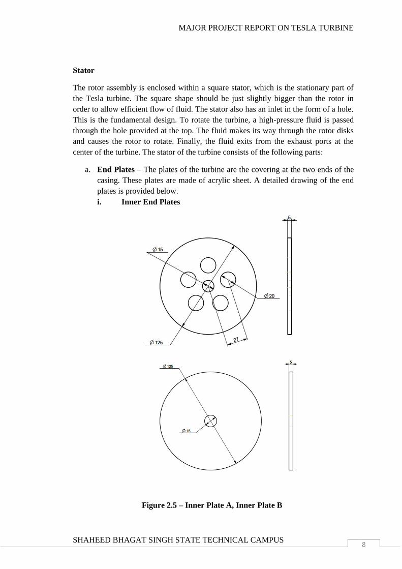
a. End Plates – The plates of the turbine are the covering at the two ends of the
casing. These plates are made of acrylic sheet. A detailed drawing of the end
plates is provided below.
i. Inner End Plates
Figure 2.5 – Inner Plate A, Inner Plate B

MAJOR PROJECT REPORT ON TESLA TURBINE
SHAHEED BHAGAT SINGH STATE TECHNICAL CAMPUS 9
ii. Outer End Plates
Figure 2.6 – Outer Plate A
Figure 2.7 – Outer Plate B

MAJOR PROJECT REPORT ON TESLA TURBINE
SHAHEED BHAGAT SINGH STATE TECHNICAL CAMPUS 10
b. Casing – The casing of turbine is cylindrical in shape and is made up of PVC.
The rotor of the turbine rotates in this cylindrical casing which is of slightly
larger diameter then the disks of the rotor. There is a hole provided at the top
of the casing which is for the inlet of the air through the nozzle. The detailed
drawing showing the casing of the turbine in shown below.
Figure 2.8 – Turbine Casing
MAJOR PROJECT REPORT ON TESLA TURBINE
SHAHEED BHAGAT SINGH STATE TECHNICAL CAMPUS 11
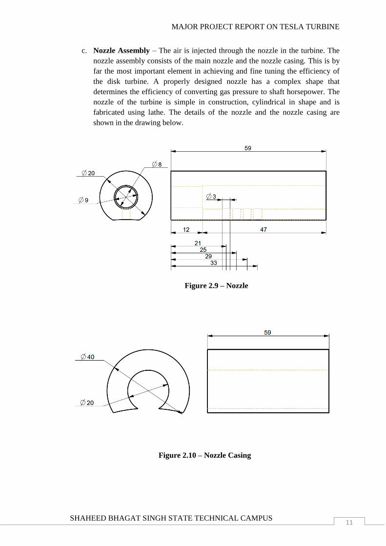
c. Nozzle Assembly – The air is injected through the nozzle in the turbine. The
nozzle assembly consists of the main nozzle and the nozzle casing. This is by
far the most important element in achieving and fine tuning the efficiency of
the disk turbine. A properly designed nozzle has a complex shape that
determines the efficiency of converting gas pressure to shaft horsepower. The
nozzle of the turbine is simple in construction, cylindrical in shape and is
fabricated using lathe. The details of the nozzle and the nozzle casing are
shown in the drawing below.
Figure 2.9 – Nozzle
Figure 2.10 – Nozzle Casing
MAJOR PROJECT REPORT ON TESLA TURBINE
SHAHEED BHAGAT SINGH STATE TECHNICAL CAMPUS 12
2.2 AIR COMPRESSION UNIT
The air compression unit consists of the exercising machine which is used as the
compressor for the system. The air is compressed by the muscular force applied on the
exercising machine by the user. This compressed air is transferred to the storage
cylinder via non-return valves. The compression unit comprises of the following
parts:
a. Foot Air Pump
b. Pneumatic Non-return Valves
2.2.1 Foot Air Pump
An air pump is a device for pushing air. Examples include a bicycle pump that are
used to aerate an aquarium or a pond via an air stone a gas compressor used to power
a pneumatic tool, air horn or pipe organ, a bellows used to encourage a fire; a vacuum
cleaner and a vacuum pump.
These pumps are often not specifically designed for bicycle use. They do not generate
very high pressures so do not work well for narrow road-bike tires, but are fine for
large low-pressure tires as found on mountain bikes.
The pump which we are using here is a foot pump, containing a heavy duty cylinder
of diameter 8cm working pressure is 0-100 Psi or 0-7 bar pressure. The pressure
gauge has been removed from it for our convenience and the proper transference of
pressurized air with the help of hose pipe.
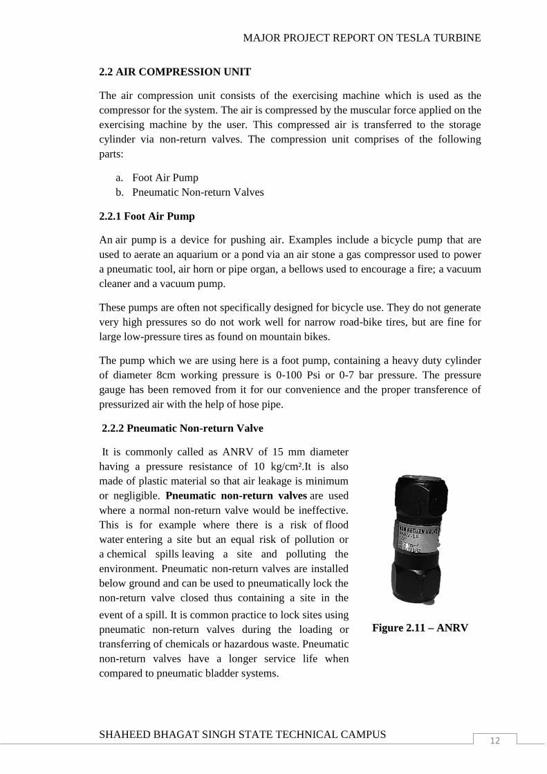
2.2.2 Pneumatic Non-return Valve
It is commonly called as ANRV of 15 mm diameter
having a pressure resistance of 10 kg/cm².It is also
made of plastic material so that air leakage is minimum
or negligible. Pneumatic non-return valves are used
where a normal non-return valve would be ineffective.
This is for example where there is a risk of flood
water entering a site but an equal risk of pollution or
a chemical spills leaving a site and polluting the
environment. Pneumatic non-return valves are installed
below ground and can be used to pneumatically lock the
non-return valve closed thus containing a site in the
event of a spill. It is common practice to lock sites using
pneumatic non-return valves during the loading or
transferring of chemicals or hazardous waste. Pneumatic
non-return valves have a longer service life when
compared to pneumatic bladder systems.
Figure 2.11 – ANRV
MAJOR PROJECT REPORT ON TESLA TURBINE
SHAHEED BHAGAT SINGH STATE TECHNICAL CAMPUS 13
2.3 STORAGE UNIT
The air compressed using the pumps is stored in a cylinder. A pressure gauge is
mounted on the cylinder for measuring the pressure inside the cylinder. The stored air
transferred to turbine for the required purpose. The flow of air to the turbine is
controlled by a gate valve. The storage unit consists of the following parts:
a. Cylinder
b. Pressure Gauge
c. Gate Valve
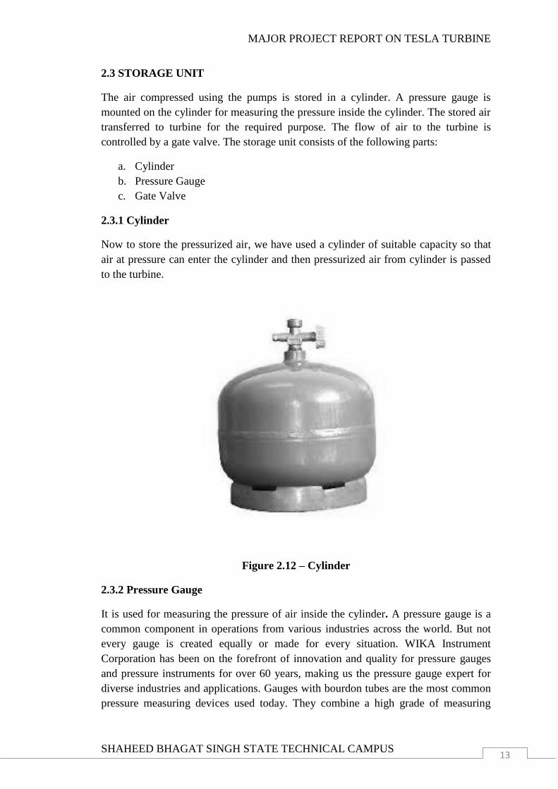
2.3.1 Cylinder
Now to store the pressurized air, we have used a cylinder of suitable capacity so that
air at pressure can enter the cylinder and then pressurized air from cylinder is passed
to the turbine.
Figure 2.12 – Cylinder
2.3.2 Pressure Gauge
It is used for measuring the pressure of air inside the cylinder. A pressure gauge is a
common component in operations from various industries across the world. But not
every gauge is created equally or made for every situation. WIKA Instrument
Corporation has been on the forefront of innovation and quality for pressure gauges
and pressure instruments for over 60 years, making us the pressure gauge expert for
diverse industries and applications. Gauges with bourdon tubes are the most common
pressure measuring devices used today. They combine a high grade of measuring
MAJOR PROJECT REPORT ON TESLA TURBINE
SHAHEED BHAGAT SINGH STATE TECHNICAL CAMPUS 14
technology, simple operation, ruggedness and flexibility with the advantages of
industrial and cost-effective production. Needing no external power supply, bourdon
tube gauges are the best choice for most applications. Pressure gauges are crucial
components of most processing systems. In these environments, a pressure gauge
needs to be reliable, accurate and easy to read to help prevent failure in everyday
operations. Therefore, how a gauge is constructed and tested is extremely important
for reliability, safety and peace-of-mind. After all, failures can cost time, money and
productivity loss.
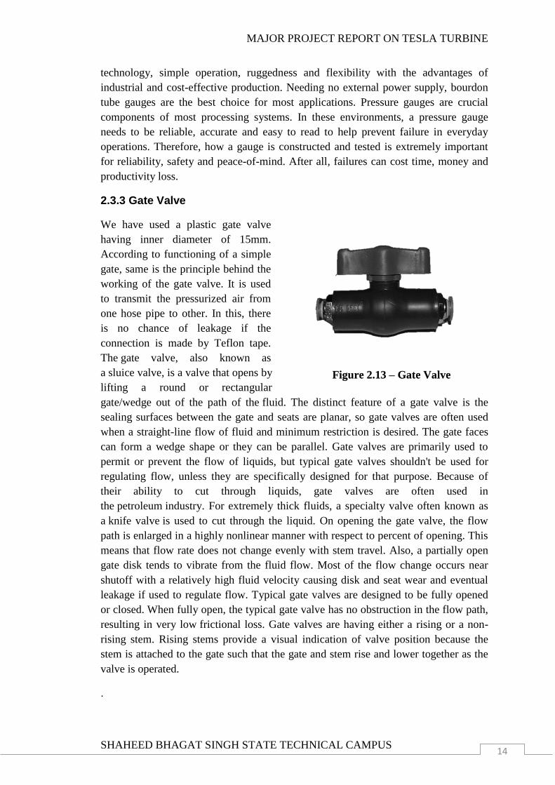
2.3.3 Gate Valve
We have used a plastic gate valve
having inner diameter of 15mm.
According to functioning of a simple
gate, same is the principle behind the
working of the gate valve. It is used
to transmit the pressurized air from
one hose pipe to other. In this, there
is no chance of leakage if the
connection is made by Teflon tape.
The gate valve, also known as
a sluice valve, is a valve that opens by
lifting a round or rectangular
gate/wedge out of the path of the fluid. The distinct feature of a gate valve is the
sealing surfaces between the gate and seats are planar, so gate valves are often used
when a straight-line flow of fluid and minimum restriction is desired. The gate faces
can form a wedge shape or they can be parallel. Gate valves are primarily used to
permit or prevent the flow of liquids, but typical gate valves shouldn't be used for
regulating flow, unless they are specifically designed for that purpose. Because of
their ability to cut through liquids, gate valves are often used in
the petroleum industry. For extremely thick fluids, a specialty valve often known as
a knife valve is used to cut through the liquid. On opening the gate valve, the flow
path is enlarged in a highly nonlinear manner with respect to percent of opening. This
means that flow rate does not change evenly with stem travel. Also, a partially open
gate disk tends to vibrate from the fluid flow. Most of the flow change occurs near
shutoff with a relatively high fluid velocity causing disk and seat wear and eventual
leakage if used to regulate flow. Typical gate valves are designed to be fully opened
or closed. When fully open, the typical gate valve has no obstruction in the flow path,
resulting in very low frictional loss. Gate valves are having either a rising or a non-
rising stem. Rising stems provide a visual indication of valve position because the
stem is attached to the gate such that the gate and stem rise and lower together as the
valve is operated.
.
Figure 2.13 – Gate Valve

MAJOR PROJECT REPORT ON TESLA TURBINE
SHAHEED BHAGAT SINGH STATE TECHNICAL CAMPUS 15
2.4 POWER GENERATION UNIT
The power generated by the turbine is transferred to an electricity generator using a
pair of spur gear. The electricity then generated is can be used for the required
purposes. For the purpose here we have used it for lighting the LED‟s. The following
parts are covered in this unit:
a. Dynamo
b. Spur Gear
c. LED(Light Emitting Diode)
2.4.1 Dynamo
A dynamo is an electrical generator that produces direct current with the use of
a commutator. Dynamos were the first electrical generators capable of delivering
power for industry, and the foundation upon which many other later electric-power
conversion devices were based, including the electric motor, the alternating-
current alternator, and the rotary converter. Today, the simpler alternator dominates
large scale power generation, for efficiency, reliability and cost reasons. A dynamo
has the disadvantages of a mechanical commutator. Also converting alternating to
direct current using power rectification devices (vacuum tube or more recently solid
state) is effective and usually economic. The word dynamo (from the Greek word
dynamis; meaning power) was originally another name for an electrical generator, and
still has some regional usage as a replacement for the word generator. A small
electrical generator built into the hub of a bicycle wheel to power lights is called a hub
dynamo. The dynamo uses rotating coils of wire and magnetic fields to convert
mechanical rotation into a pulsing direct electric current through Faraday's law of
induction. A dynamo machine consists of a stationary structure, called the stator
which provides a constant magnetic field and a set of rotating windings called
the armature which turn within that field. The motion of the wire within the magnetic
field causes the field to push on the electrons in the metal, creating an electric current
in the wire. On small machines the constant magnetic field may be provided by one or
more permanent magnets larger machines have the constant magnetic field provided
one or more electromagnets which are usually called field coils. The commutator was
needed to produce direct current. When a loop of wire rotates in a magnetic field, the
potential induced in it reverses with each half turn, generating an alternating current.
However, in the early days of electric experimentation, alternating current generally
had no known use. The few uses for electricity, such as electroplating, used direct
current provided by messy liquid batteries. Dynamos were invented as a replacement
for batteries. The commutator is essentially a rotary switch. It consists of a set of
contacts mounted on the machine's shaft, combined with graphite-block stationary
contacts, called "brushes", because the earliest such fixed contacts were metal
brushes. The commutator reverses the connection of the windings to the external
circuit when the potential reverses, so instead of alternating current, a pulsing direct
current is produced.
MAJOR PROJECT REPORT ON TESLA TURBINE
SHAHEED BHAGAT SINGH STATE TECHNICAL CAMPUS 16
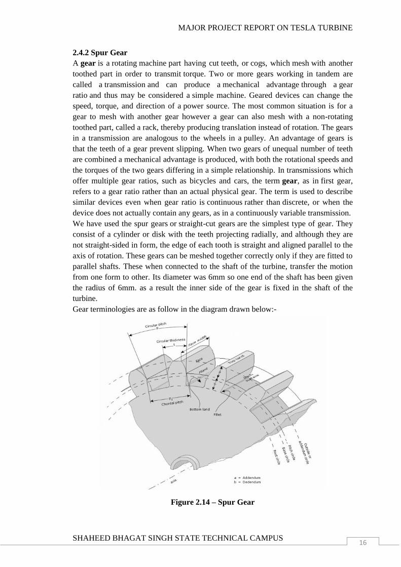
2.4.2 Spur Gear
A gear is a rotating machine part having cut teeth, or cogs, which mesh with another
toothed part in order to transmit torque. Two or more gears working in tandem are
called a transmission and can produce a mechanical advantage through a gear
ratio and thus may be considered a simple machine. Geared devices can change the
speed, torque, and direction of a power source. The most common situation is for a
gear to mesh with another gear however a gear can also mesh with a non-rotating
toothed part, called a rack, thereby producing translation instead of rotation. The gears
in a transmission are analogous to the wheels in a pulley. An advantage of gears is
that the teeth of a gear prevent slipping. When two gears of unequal number of teeth
are combined a mechanical advantage is produced, with both the rotational speeds and
the torques of the two gears differing in a simple relationship. In transmissions which
offer multiple gear ratios, such as bicycles and cars, the term gear, as in first gear,
refers to a gear ratio rather than an actual physical gear. The term is used to describe
similar devices even when gear ratio is continuous rather than discrete, or when the
device does not actually contain any gears, as in a continuously variable transmission.
We have used the spur gears or straight-cut gears are the simplest type of gear. They
consist of a cylinder or disk with the teeth projecting radially, and although they are
not straight-sided in form, the edge of each tooth is straight and aligned parallel to the
axis of rotation. These gears can be meshed together correctly only if they are fitted to
parallel shafts. These when connected to the shaft of the turbine, transfer the motion
from one form to other. Its diameter was 6mm so one end of the shaft has been given
the radius of 6mm. as a result the inner side of the gear is fixed in the shaft of the
turbine.
Gear terminologies are as follow in the diagram drawn below:-
Figure 2.14 – Spur Gear
MAJOR PROJECT REPORT ON TESLA TURBINE
SHAHEED BHAGAT SINGH STATE TECHNICAL CAMPUS 17
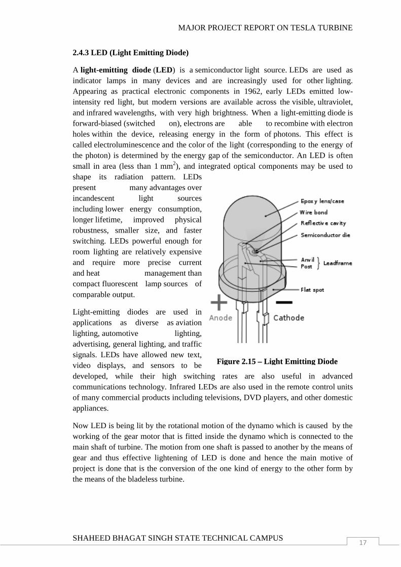
2.4.3 LED (Light Emitting Diode)
A light-emitting diode (LED) is a semiconductor light source. LEDs are used as
indicator lamps in many devices and are increasingly used for other lighting.
Appearing as practical electronic components in 1962, early LEDs emitted low-
intensity red light, but modern versions are available across the visible, ultraviolet,
and infrared wavelengths, with very high brightness. When a light-emitting diode is
forward-biased (switched on), electrons are able to recombine with electron
holes within the device, releasing energy in the form of photons. This effect is
called electroluminescence and the color of the light (corresponding to the energy of
the photon) is determined by the energy gap of the semiconductor. An LED is often
small in area (less than 1 mm2), and integrated optical components may be used to
shape its radiation pattern.
LEDs
present many advantages over
incandescent light sources
including lower energy consumption,
longer lifetime, improved physical
robustness, smaller size, and faster
switching. LEDs powerful enough for
room lighting are relatively expensive
and require more precise current
and heat management than
compact fluorescent lamp sources of
comparable output.
Light-emitting diodes are used in
applications as diverse as aviation
lighting, automotive lighting,
advertising, general lighting, and traffic
signals. LEDs have allowed new text,
video displays, and sensors to be
developed, while their high switching rates are also useful in advanced
communications technology. Infrared LEDs are also used in the remote control units
of many commercial products including televisions, DVD players, and other domestic
appliances.
Now LED is being lit by the rotational motion of the dynamo which is caused by the
working of the gear motor that is fitted inside the dynamo which is connected to the
main shaft of turbine. The motion from one shaft is passed to another by the means of
gear and thus effective lightening of LED is done and hence the main motive of
project is done that is the conversion of the one kind of energy to the other form by
the means of the bladeless turbine.
Figure 2.15 – Light Emitting Diode
MAJOR PROJECT REPORT ON TESLA TURBINE
SHAHEED BHAGAT SINGH STATE TECHNICAL CAMPUS 18
CHAPTER 3
MATERIALS USED
Several kinds of materials are used for the fabrication of the project. The material
used for the fabrication purpose is carefully selected so that the required purpose is
fulfilled in the best economical way. Different materials used in the fabrication of the
project are discussed below.
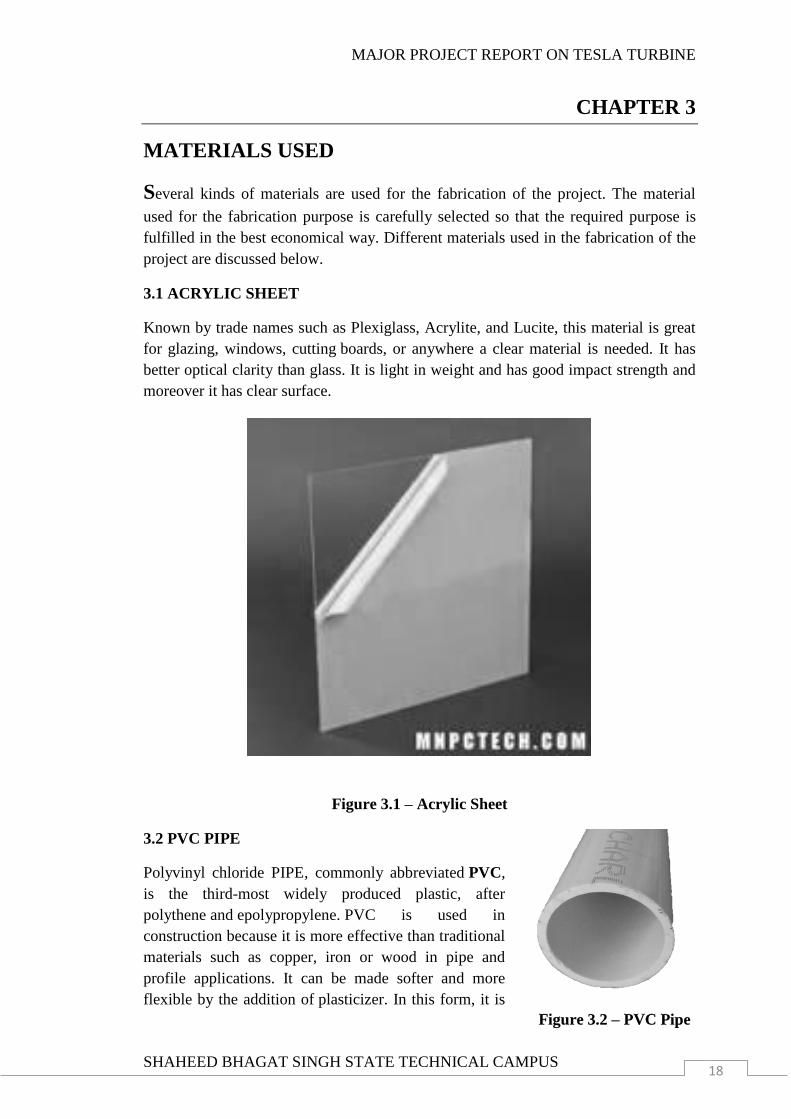
3.1 ACRYLIC SHEET
Known by trade names such as Plexiglass, Acrylite, and Lucite, this material is great
for glazing, windows, cutting boards, or anywhere a clear material is needed. It has
better optical clarity than glass. It is light in weight and has good impact strength and
moreover it has clear surface.
Figure 3.1 – Acrylic Sheet
3.2 PVC PIPE
Polyvinyl chloride PIPE, commonly abbreviated PVC,
is the third-most widely produced plastic, after
polythene and epolypropylene. PVC is used in
construction because it is more effective than traditional
materials such as copper, iron or wood in pipe and
profile applications. It can be made softer and more
flexible by the addition of plasticizer. In this form, it is
Figure 3.2 – PVC Pipe
MAJOR PROJECT REPORT ON TESLA TURBINE
SHAHEED BHAGAT SINGH STATE TECHNICAL CAMPUS 19
also used in clothing and upholstery, inflatable products and many applications in
which it replaces rubber.
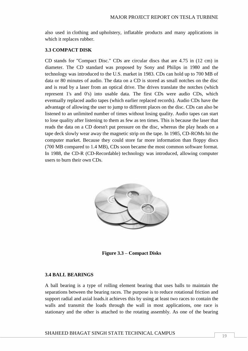
3.3 COMPACT DISK
CD stands for "Compact Disc." CDs are circular discs that are 4.75 in (12 cm) in
diameter. The CD standard was proposed by Sony and Philips in 1980 and the
technology was introduced to the U.S. market in 1983. CDs can hold up to 700 MB of
data or 80 minutes of audio. The data on a CD is stored as small notches on the disc
and is read by a laser from an optical drive. The drives translate the notches (which
represent 1's and 0's) into usable data. The first CDs were audio CDs, which
eventually replaced audio tapes (which earlier replaced records). Audio CDs have the
advantage of allowing the user to jump to different places on the disc. CDs can also be
listened to an unlimited number of times without losing quality. Audio tapes can start
to lose quality after listening to them as few as ten times. This is because the laser that
reads the data on a CD doesn't put pressure on the disc, whereas the play heads on a
tape deck slowly wear away the magnetic strip on the tape. In 1985, CD-ROMs hit the
computer market. Because they could store far more information than floppy discs
(700 MB compared to 1.4 MB), CDs soon became the most common software format.
In 1988, the CD-R (CD-Recordable) technology was introduced, allowing computer
users to burn their own CDs.
Figure 3.3 – Compact Disks
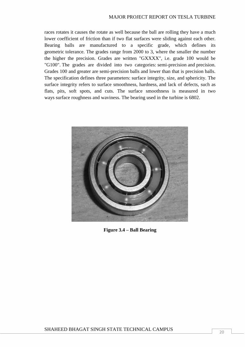
3.4 BALL BEARINGS
A ball bearing is a type of rolling element bearing that uses balls to maintain the
separations between the bearing races. The purpose is to reduce rotational friction and
support radial and axial loads.it achieves this by using at least two races to contain the
walls and transmit the loads through the wall in most applications, one race is
stationary and the other is attached to the rotating assembly. As one of the bearing
MAJOR PROJECT REPORT ON TESLA TURBINE
SHAHEED BHAGAT SINGH STATE TECHNICAL CAMPUS 20
races rotates it causes the rotate as well because the ball are rolling they have a much
lower coefficient of friction than if two flat surfaces were sliding against each other.
Bearing balls are manufactured to a specific grade, which defines its
geometric tolerance. The grades range from 2000 to 3, where the smaller the number
the higher the precision. Grades are written "GXXXX", i.e. grade 100 would be
"G100". The grades are divided into two categories: semi-precision and precision.
Grades 100 and greater are semi-precision balls and lower than that is precision balls.
The specification defines three parameters: surface integrity, size, and sphericity. The
surface integrity refers to surface smoothness, hardness, and lack of defects, such as
flats, pits, soft spots, and cuts. The surface smoothness is measured in two
ways surface roughness and waviness. The bearing used in the turbine is 6802.
Figure 3.4 – Ball Bearing
MAJOR PROJECT REPORT ON TESLA TURBINE
SHAHEED BHAGAT SINGH STATE TECHNICAL CAMPUS 21
CHAPTER 4
WORKING
Adhesion and viscosity are the two properties of any fluid, these two properties work
together in the tesla turbine to transfer energy from the fluid to the rotor or vice versa.
As the fluid moves past each disk, adhesive forces cause the fluid molecules just
above the metal surface to slow down and stick. The molecules just above those at the
surface slow down when they collide with the molecules sticking to the surface. These
molecules in turn slow down the flow just above them. The farther one moves away
from the surface, the fewer the collisions affected by the object surface. At the same
time, viscous forces cause the molecules of the fluid to resist separation. This
generates a pulling force that is transmitted to the disk, causing the disk to move in
the direction of the fluid. The thin layer of fluid that interacts with the disk surface in
this way is called the boundary layer, and the interaction of the fluid with the solid
surface is called the boundary layer effect. As a result of this effect, the propelling
fluid follows a rapidly accelerated spiral path along the disk faces until it reaches a
suitable exit with proper use of the analytical results, the rotor efficiency using
laminar flow can be very high, even above 95%.
The reason why the Tesla turbine rotates with such high rpm can be found in two very
basic properties of fluids: adhesion and viscosity. Adhesion is defined as the
propensity of dissimilar molecules to get attracted. Viscosity is defined as the
resistance developed within a fluid when subjected to flow. These two properties
produce a combined effect in the turbine for transferring the energy from the air/water
to the rotor or the other way round in the following manner.
As the fluid moves over each disk, the force of adhesion slows down the fluid
molecules just above the disc and thus, they stick on to the surface. The molecules
just above the ones which are glued to the surface slow down when they strike them.
This process continues level by level and thus a chain reaction is initiated. The farther
the distance from the surface, the smaller the effect of adhesion. But the viscous
forces prevent the molecules from separation. This results in a torque being
transmitted to the disk, which imparts rotation to the disk in the direction in which the
fluid interacts with it.
Thus, this thin layer of fluid which imparts torque to the discs by acting on the
boundaries of the fluid-disc contact surface is called boundary layer and the net effect
is called boundary layer effect. The net results of this whole process in that fluid takes
a spiral path from the boundary to the center of the disc, from it exists through the
exhaust holes provided, thereby rotating the discs rapidly.
MAJOR PROJECT REPORT ON TESLA TURBINE
SHAHEED BHAGAT SINGH STATE TECHNICAL CAMPUS 22
4.1 MECHANISM
The Tesla turbine is a bladeless centripetal flow turbine. It is referred to as a bladeless
turbine because of its property that fluid impinges on the blade as a same done in the
convectional turbine.
A Tesla turbine consist of a smooth discs with nozzles applying a moving gas to the
edge of the disk by means of viscosity and the adhesion of the surface layer of the gas.
As the gas flows and adds energy to the disks, it spirals into the center exhaust since
the rotor has no projections, it is very sturdy.
Now explaining the detailed mechanism involved in the process of the turbine. Firstly
the main objective of the working of the turbine is to rotate the disk connected to the
shaft .For this to be done. We need air pressure to be applied in tangential direction
with respect to the discs connected to the rotor as well as shaft. The air pressure must
be more than 40 Psi.
For creating the air pressure, we have applied a mechanism consisting of two air-
pumps (used for Exercising) that are fixed on a plyboard which is of 18*18 inch. Set
at the center of the plywood. The air is transferred to a cylinder through T-joint
connected via non-return valves of 10kg/cm2. The air then compressed at 50psi is sent
to the turbine through pneumatic pipe and the flow of the air is controlled by a gate
valve. Compressed air is passed to the turbine through the air inlet nozzle at the top of
the turbine. The air injected through the nozzle passes through the gaps between the
disks creating a boundary layer which results in rotation of the shaft. The shaft then
transfer the power to a dynamo generating electric current which is here used to lit the
LED‟s and also can be used for various purposes.
MAJOR PROJECT REPORT ON TESLA TURBINE
SHAHEED BHAGAT SINGH STATE TECHNICAL CAMPUS 23
CHAPTER 5
COMMERCIAL VIABILITY OF THE NEW PROPOSALS
5.1 THE EFFICIENCY FACTOR - Tesla Turbine is more efficient than most of the
prime movers which are currently in use commercially. The following chart shows the
average efficiency of a bladed turbine (Pelton turbine, Kaplan turbine, Francis turbine
etc.), a gas piston, a diesel engine, a fuel cell and a Tesla Turbine.
Thus, if the Tesla turbine is adopted on a commercial basis, the efficiency level of the
process, be it generating current or pumping water, will see a marked improvement
when compared to the current scenario. By adopting the newly proposed fluid and
rotor design, this efficiency is expected to increase even further, thereby pushing the
cause of the Tesla Turbine even further.
5.2 THE COST FACTOR- The following is the comparison between the estimated
cost of the new proposed Tesla turbine and the other machines mentioned earlier.
Here, it can be seen that the expected cost of the proposed Tesla Turbine is not too
high when compared to its peers. This expected cost has been calculated after taking
into account the cost of the laminated composite rotors. The costs of the other
machines are their average market costs. Thus, the Tesla turbine provides an
alternative solution to today‟s energy problems, at a cost which is much lower than
the other commercially wide-spread machines.
5.3 THE SUSTAINABILITY FACTOR - In today‟s world which emphasizes green
technologies, the Tesla turbine is an ideal candidate for future power generation,
water pumping etc. The fact that the properties of adhesion and viscosity combine
together to generate much more power than the power consumed by the compressor
which is used to provide the compressed air to the Tesla Turbine rotor is of much
importance. Even the power consumed by the air heater to heat the air to 80C will be
compensated in the former of a much higher torque generation by the proposed
modified Tesla turbine. Especially in areas such as hydraulic power applications, such
a high torque can play a very significant role.
5.4 CALCULATING THE IDEAL NUMBER OF DISCS - To estimate the total
number of disks for the turbine, assume that at a given internal circumference of the
disk, the flow Reynolds number is less than 2300. Taking the number of disc as
according to our need. Then assuming it to be a number of 8 and proceeding further
operations.
5.5 EFFICIENCY AND CALCULATION - Tesla's time, the efficiency of
conventional turbines was low because the aerodynamic theory needed for effective
blade design did not exist and the low quality of materials available to construct those
blades put severe limitations on operating speeds and temperatures. The efficiency of
a conventional turbine is related to the pressure difference between the intake and the
MAJOR PROJECT REPORT ON TESLA TURBINE
SHAHEED BHAGAT SINGH STATE TECHNICAL CAMPUS 24
exhaust. To achieve a higher pressure difference very hot fluids such as superheated
steam are used which is why the availability of higher temperature materials allow
higher efficiencies. If the turbine uses a gas which is liquid at room temperature then
you can use a condenser after the exhaust to increase the pressure difference.
Tesla's design sidestepped the key drawbacks of the bladed turbine. It does suffer
from other problems such as shear losses and flow restrictions. Some of Tesla
turbine's advantages lie in relatively low flow rate applications or when small
applications are called for. The disks need to be as thin as possible at the edges in
order not to introduce turbulence as the fluid leaves the disks. This translates to
needing to increase the number of disks as the flow rate increases. Maximum
efficiency comes in this system when the inter-disk spacing approximates the
thickness of the boundary layer, and since boundary layer thickness is dependent on
viscosity and pressure, the claim that a single design can be used efficiently for a
variety of fuels and fluids is incorrect. A Tesla turbine differs from a conventional
turbine only in the mechanism used for transferring energy to the shaft. Various
analyses demonstrate the flow rate between the disks must be kept relatively low to
maintain efficiency. Reportedly, the efficiency of the Tesla turbine drops with
increased load. Under light load, the spiral taken by the fluid moving from the intake
to the exhaust is a tight spiral, undergoing many rotations. Under load, the number of
rotations drops and the spiral becomes progressively shorter. This will increase the
shear losses and also reduce the efficiency because the gas is in contact with the discs
for less distance.
Efficiency is a function of power output. A light load makes for high efficiency and a
heavy load, which increases the slip in the turbine and lowers the efficiency, though
this is not exclusive to Tesla turbines. The turbine effeciency of the gas Tesla turbine
is estimated to be above 60, reaching a maximum of 95 percent. Keep in mind that
turbine efficiency is different from the cycle efficiency of the engine using the
turbine. Axial turbines which operate today in steam plants or jet engines have
efficiencies of about 60 - 70% (Siemens Turbines Data). This is different from the
cycle efficiencies of the plant or engine which are between approximately 25% and
42%, and are limited by any to fall below the turbine efficiency. Tesla claimed that a
steam version of his device would achieve around 95 percent efficiency. Actual tests
of a Tesla Steam Turbine at the Westinghouse works showed a steam rate of 38
pounds per horsepower hour, corresponding to a turbine efficiency in the range of
20%, while contemporary steam turbines could often achieve turbine efficiencies of
well over 50%. The methods and apparatus for the propulsion of
fluids and thermodynamic transformation of energy were disclosed in various patents.
The thermodynamic efficiency is a measure of how well it performs compared to
an isentropic case. It is the ratio of the ideal to the actual work input/output. This can
be taken to be the ratio of the ideal change in enthalpy to the real enthalpy for the
same change in pressure.
MAJOR PROJECT REPORT ON TESLA TURBINE
SHAHEED BHAGAT SINGH STATE TECHNICAL CAMPUS 25
In the 1950s, Warren Rice attempted to re-create Tesla's experiments, but he did
not perform these early tests on a pump built strictly in line with the Tesla's patented
design (it, among other things, was not a Tesla multiple staged turbine nor did it
possess Tesla's nozzle). Rice's experimental single stage system's working fluid was
air. Rice's test turbines, as published in early reports, produced an overall measured
efficiency of 36% to 41% for a single stage. Higher percentages would be expected if
designed as originally proposed by Tesla.
In his final work with the Tesla turbine and published just prior to his retirement, Rice
conducted a bulk-parameter analysis of model laminar flow in multiple disk turbines.
A very high claim for rotor efficiency (as opposed to overall device efficiency) for
this design was published in 1991 entitled "Tesla Turbo machinery". This paper
states:
"With proper use of the analytical results, the rotor efficiency using laminar flow can
be very high, even above 95%. However, in order to attain high rotor efficiency, the
flow rate number must be made small which means high rotor efficiency is achieved
at the expense of using a large number of disks and hence a physically larger rotor."
Modern multiple stage bladed turbines typically reach 60% - 70% efficiency, while
large steam turbines often show turbine efficiency of over 90% in
practice. Volute rotor matched Tesla-type machines of reasonable size with common
fluids (steam, gas, and water) would also be expected to show efficiencies in the
vicinity of 60% - 70% and possibly higher.
MAJOR PROJECT REPORT ON TESLA TURBINE
SHAHEED BHAGAT SINGH STATE TECHNICAL CAMPUS 26
CHAPTER 6
UTILITIES
Tesla Turbine is more efficient than most of the prime movers which are currently in
use commercially. The following chart shows the average efficiency of a bladed
turbine (Pelton turbine, Kaplan turbine, Francis turbine etc.), a gas piston, a diesel
engine, a fuel cell and a Tesla Turbine. Thus, if the Tesla turbine is adopted on a
commercial basis, the efficiency level of the process, be it generating current or
pumping water, will see a marked improvement when compared to the current
scenario. By adopting the newly proposed fluid and rotor design, this efficiency is
expected to increase even further, thereby pushing the cause of the Tesla Turbine even
further. In today‟s world which emphasizes green technologies, the Tesla turbine is an
ideal candidate for future power generation, water pumping etc. The fact that the
properties of adhesion and viscosity combine together to generate much more power
than the power consumed by the compressor which is used to provide the compressed
air to the Tesla Turbine rotor is of much importance. Even the power consumed by the
air heater to heat the air to 80C will be compensated in the former of a much higher
torque generation by the proposed modified Tesla turbine. Especially in areas such as
hydraulic power applications, such a high torque can play a very significant role.
6.1 ADVANTAGES
Simple in construction.
Corrosion and cavitation is less.
Pollution free.
Low cost to produce and maintain.
This type of equipment can be operated at a wide range of working medium
parameters without any danger and malfunction.
It is not so sensitive to a partially polluted working medium, since the fluid
flow is parallel to disks, so it can be operated with saturated steam.
This turbine can be adjusted to different circumstances by applying a few
cross section has to be adjusted to the actual demand which is an
interchangeable part of the equipment
It is a bladeless turbine working smoothly by spinning of central disc by
friction from a gas or fluid. Since the turbine itself has no drawback, it is
extremely stable.
MAJOR PROJECT REPORT ON TESLA TURBINE
SHAHEED BHAGAT SINGH STATE TECHNICAL CAMPUS 27
6.2 DISADVANTAGES
Low rotor torque.
Often not suitable for a direct replacement for conventional turbines and
pumps, without changes to the machinery it is interacting with.
Proof of its efficiency compared to conventional turbines is still questionable
and needs more research.
It has remained underdeveloped and hence design improvements are still
being made.
Need more changes to the initial design to reach theoretical values.
6.3 APPLICATIONS
Tesla turbine has not seen widespread commercial use since its invention.
The Tesla pump, however, has been commercially available since 1982 and is
used to pump fluids that are abrasive, viscous, contain solids, shear sensitive
or otherwise difficult to handle with other pumps.
Applications of the Tesla turbine as a multiple-disk centrifugal blood pump
have yielded promising results.
Biomedical engineering research on such applications has been continued into
the 21st century.
MAJOR PROJECT REPORT ON TESLA TURBINE
SHAHEED BHAGAT SINGH STATE TECHNICAL CAMPUS 28
CHAPTER 7
CONCLUSION AND SCOPE FOR FUTURE WORK
7.1 CONCLUSION
In this project, an effort has been made to push the case of the
commercialization of the Tesla Turbine. Tesla turbine should be considered in
applications in which conventional machines are inadequate. This includes
applications for small shaft power, or the use of very viscous fluid or non-
Newtonian fluids.
Multiple-disk turbine can operate with abrasive two-phase flow mixtures with
less erosion of material from the rotor. For that reason, they should be further
investigated for applications to produce power from geothermal steam and
particle-laden industrial gas flows. There may also be unique applications
possible using ceramic disks.
There is considerable evidence that multiple-disk turbine can be quieter in
operation than is conventional machinery and that the noise produced is more
nearly „„white‟‟ noise without a prevailing sound signature. Multiple-disk
pumps are well known to resist cavitation. It is the only type of turbine that
can be easily constructed in a relatively primitive machine shop.
Although Tesla himself described that the Tesla Turbine was his greatest
invention, it has not found widespread acceptance. It is expected that by
analyzing the reasons for that and suggesting improvements like a new
working fluid and a new rotor material, a small step forward to commercialize
this turbine has been made. The higher torque generation of such a modified
Tesla Turbine is expected to revive its fortunes in the commercial market.
7.2 SCOPE FOR FUTURE WORK
It has been found that the efficiency of the rotor can be very high, at least
equal to that achieved by conventional rotors. But it has proved very difficult
to achieve efficient nozzles in the case of turbines. For pumps and
compressors, efficient diffusion after the rotor has proven difficult to achieve.
As a result, only modest machine efficiencies have been demonstrated.
The ability of the laminated composite material, with which the rotor is to be
constructed, to absorb high stress concentration levels, both thermal and
structural, will prove to be beneficial.
MAJOR PROJECT REPORT ON TESLA TURBINE
SHAHEED BHAGAT SINGH STATE TECHNICAL CAMPUS 29
CHAPTER 8
BIBLIOGRAPHY
J. H. Armstrong, “An Investigation of the Performance of a Modified Tesla
Turbine” M.S. Thesis, Georgia Institute of Technology, June (1952).
S. K. P. Young, “The Investigation and Analysis of the Tesla Turbine,” M.S.
Thesis, University of Illinois (1957).
Tesla Turbomachinery by Warren Rice Arizona State University, Tempe,
Arizona, U.S.A.
www.google.com
www.mechmagic.com
www.iitinfo.com
www.wikipedia.com
Dssault‟s System software
Microsoft office