reported by aci committee 371 aci 371r-16 · concrete water storage tanks based on practices used...
TRANSCRIPT

Guide for the Analysis, Design, and Construction of Elevated Concrete and Composite Steel-Concrete Water Storage TanksReported by ACI Committee 371
AC
I 371
R-1
6
First PrintingJune 2016
ISBN: 978-1-945487-00-2
Guide for the Analysis, Design, and Construction of Elevated Concrete and Composite Steel-Concrete Water Storage Tanks
Copyright by the American Concrete Institute, Farmington Hills, MI. All rights reserved. This material may not be reproduced or copied, in whole or part, in any printed, mechanical, electronic, film, or other distribution and storage media, without the written consent of ACI.
The technical committees responsible for ACI committee reports and standards strive to avoid ambiguities, omissions, and errors in these documents. In spite of these efforts, the users of ACI documents occasionally find information or requirements that may be subject to more than one interpretation or may be incomplete or incorrect. Users who have suggestions for the improvement of ACI documents are requested to contact ACI via the errata website at http://concrete.org/Publications/DocumentErrata.aspx. Proper use of this document includes periodically checking for errata for the most up-to-date revisions.
ACI committee documents are intended for the use of individuals who are competent to evaluate the significance and limitations of its content and recommendations and who will accept responsibility for the application of the material it contains. Individuals who use this publication in any way assume all risk and accept total responsibility for the application and use of this information.
All information in this publication is provided “as is” without warranty of any kind, either express or implied, including but not limited to, the implied warranties of merchantability, fitness for a particular purpose or non-infringement.
ACI and its members disclaim liability for damages of any kind, including any special, indirect, incidental, or consequential damages, including without limitation, lost revenues or lost profits, which may result from the use of this publication.
It is the responsibility of the user of this document to establish health and safety practices appropriate to the specific circumstances involved with its use. ACI does not make any representations with regard to health and safety issues and the use of this document. The user must determine the applicability of all regulatory limitations before applying the document and must comply with all applicable laws and regulations, including but not limited to, United States Occupational Safety and Health Administration (OSHA) health and safety standards.
Participation by governmental representatives in the work of the American Concrete Institute and in the development of Institute standards does not constitute governmental endorsement of ACI or the standards that it develops.
Order information: ACI documents are available in print, by download, on CD-ROM, through electronic subscription, or reprint and may be obtained by contacting ACI.
Most ACI standards and committee reports are gathered together in the annually revised ACI Manual of Concrete Practice (MCP).
American Concrete Institute38800 Country Club DriveFarmington Hills, MI 48331Phone: +1.248.848.3700Fax: +1.248.848.3701
www.concrete.org

This guide presents recommendations for materials, analysis, design, and construction of concrete-pedestal elevated water storage tanks, including all-concrete and composite tanks. Composite tanks consist of a steel water storage vessel supported on a cylindrical reinforced concrete pedestal.
Concrete-pedestal elevated water storage tanks are structures that present special problems not encountered in typical envi-ronmental engineering concrete structures. This guide refers to ACI 350 for design and construction of those components of the pedestal tank in contact with the stored water, and to ACI 318 for design and construction of components not in contact with the stored water. Determination of snow, wind, and seismic loads based on ASCE/SEI 7 is included. These loads conform to the requirements of national building codes that use ASCE/SEI 7 as the basis for environmental loads as well as those of local building codes. Special requirements, based on successful experience, for the unique aspects of loads, analysis, design, and construction of concrete-pedestal tanks are presented.
Keywords: composite tanks; concrete-pedestal tanks; earthquake-resistant structures; elevated water tanks; formwork (construction).
CONTENTS
CHAPTER 1—GENERAL, p. 21.1—Introduction, p. 21.2—Scope, p. 21.3—Construction documents, p. 21.4—Sample tank photos, p. 3
CHAPTER 2—NOTATION AND DEFINITIONS, p. 52.1—Notation, p. 52.2—Definitions, p. 7
CHAPTER 3—MATERIALS, p. 73.1—Materials common to both composite and concrete
tank types, p. 73.2—Materials specific to composite tanks, p. 83.3—Materials specific to concrete tanks, p. 8
CHAPTER 4—DESIGN, p. 84.1—General recommendations common to both
composite and concrete tank types, p. 84.2—Load recommendations common to both composite
and concrete tank types, p. 104.3—Design of components common to both composite
and concrete tank types, p. 154.4—Design of components specific to composite tanks, p. 204.5—Design of components specific to all-concrete tanks,
p. 22
Jeffrey S. Ward, Chair Kenneth Ryan Harvey, Secretary
ACI 371R-16
Guide for the Analysis, Design, and Construction of Elevated Concrete and Composite Steel-Concrete
Water Storage Tanks
Reported by ACI Committee 371
Voting membersKevin A. BinderNoel J. Everard
Anthony J. Galterio
John M. GonzalezCharles S. HanskatM. Reza Kianoush
Atis A. LiepinsStephen MeierRolf P. Pawski
Wes PogorzelskiBrian K. Rostedt
Consulting memberJames D. Copley Jr.
ACI Committee Reports, Guides, and Commentaries are intended for guidance in planning, designing, executing, and inspecting construction. This document is intended for the use of individuals who are competent to evaluate the significance and limitations of its content and recommendations and who will accept responsibility for the application of the material it contains. The American Concrete Institute disclaims any and all responsibility for the stated principles. The Institute shall not be liable for any loss or damage arising therefrom.
Reference to this document shall not be made in contract documents. If items found in this document are desired by the Architect/Engineer to be a part of the contract documents, they shall be restated in mandatory language for incorporation by the Architect/Engineer.
ACI 371R-16 supersedes ACI 371R-08 and was adopted and published June 2016.Copyright © 2016, American Concrete Institute.All rights reserved including rights of reproduction and use in any form or by any
means, including the making of copies by any photo process, or by electronic or mechanical device, printed, written, or oral, or recording for sound or visual reproduc-tion or for use in any knowledge or retrieval system or device, unless permission in writing is obtained from the copyright proprietors.
1

CHAPTER 5—CONSTRUCTION, p. 245.1—Construction common to both composite and
concrete tank types, p. 245.2—Construction specific to composite tanks, p. 285.3—Construction specific to concrete tanks, p. 29
CHAPTER 6—GEOTECHNICAL RECOMMENDATIONS, p. 30
6.1—General, p. 306.2—Foundation depth, p. 306.3—Settlement limits, p. 306.4—Shallow foundations, p. 316.5—Deep foundations, p. 316.6—Seismic recommendations, p. 326.7—Special considerations, p. 32
CHAPTER 7—APPURTENANCES AND ACCESSORIES, p. 32
7.1—General, p. 327.2—Pedestal access, p. 327.3—Ventilation, p. 327.4—Tank access, p. 347.5—Rigging devices for steel vessel, p. 357.6—Above-ground piping, p. 367.7—Below-ground piping, p. 367.8—Interior floors within pedestal, p. 377.9—Electrical and lighting, p. 37
CHAPTER 8—REFERENCES, p. 38Authored references, p. 39
APPENDIX A—GUIDE SUPPLEMENT, p. 39Preface, p. 39A.1—Factored design wind pressures, p. 39A.2––Composite steel concrete tank approximate period
of vibration derivation, p. 39A.3—Pedestal: vertical load capacity derivation, p. 40
CHAPTER 1—GENERAL
1.1—IntroductionThis guide provides recommendations for the design
and construction of elevated concrete and composite steel-concrete water storage tanks based on practices used in successful projects. Elevated tanks are used by municipali-ties and industry for potable water supply and fire protection. Commonly built sizes of elevated concrete and composite steel-concrete water storage tanks range from 500,000 to 3,000,000 gal. (1900 to 11,000 m3). Concrete pedestal heights range from 25 to 200 ft (8 to 60 m), depending on water system requirements and site elevation. The interior of the concrete pedestal may be used for material and equip-ment storage, office space, and other applications.
Since the 1970s, concrete-pedestal elevated water storage tanks have been constructed in North America with a steel water-containing element and an all-concrete support structure. The generic term “composite elevated tank” is often used to describe tanks of this configuration. A few
all-concrete elevated tanks have been built in the United States throughout the last century, as well as a few elevated prestressed tanks jacked into place. Elevated post-tensioned tanks as detailed in this guide have a long history in Europe, and were introduced to the U.S. market in the 1990s.
All-concrete and composite steel concrete elevated tanks are competitively marketed as complete entities, including design, and are constructed under design-build contracts using proprietary designs, details, and methods of construction. The designs, however, are frequently reviewed by owners and their consulting engineers, or by city or county officials.
Elevated tanks designed and constructed in accordance with the recommendations of this guide are expected to be durable structures that require only routine maintenance. Details of concrete surfaces that promote good drainage and avoid low areas conducive to ponding essentially eliminate the problems associated with cyclic freezing and thawing of fresh concrete in cold climates. The quality of concrete for elevated tanks in this guide meets the requirements for durable concrete as defined in ACI 201.2R. It has adequate strength, a low water-cementitious materials ratio (w/cm), and air entrainment for frost exposure. The concrete support structure loads are primarily compressive with little or no cyclic loading with stress reversal.
1.2—ScopeRecommendations supplement the general requirements
for reinforced concrete and prestressed concrete design and construction given in ACI 318, ACI 301, ACI 350, and ACI 350.5. Design and construction recommendations include materials, determination of structural loads, design of concrete elements including foundations, design of concrete or steel tank components, construction requirements, geotechnical requirements, appurtenances, and accessories. Materials, design, fabrication, and construction of the steel vessel of composite steel-concrete tanks are addressed by applicable sections of AWWA D100.
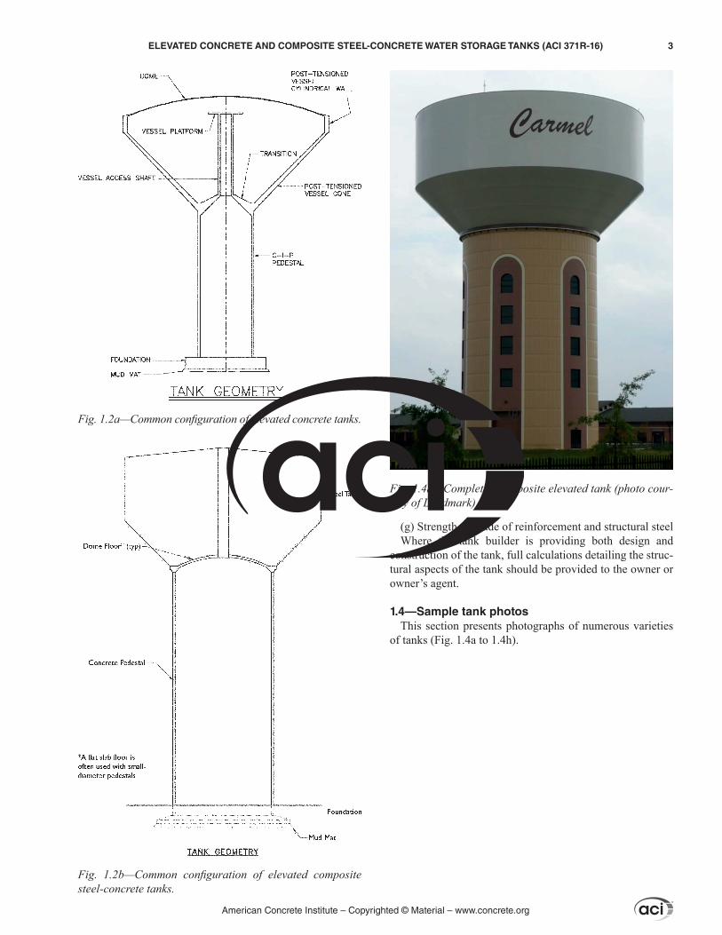
Design and construction recommendations are presented for the types of elevated concrete and composite steel-concrete water storage tanks shown in Fig. 1.2a and 1.2b. The elevated concrete tank consists of a post-tensioned concrete vessel on a cast-in-place concrete pedestal. The composite steel-concrete tank consists of a steel vessel on a cast-in-place concrete pedestal.
This guide may be used in whole or part for other tank configurations; however, the designer should determine the suitability of such use for other configurations and details.
1.3—Construction documentsConstruction documents should show all features of the
work, including:(a) Tank capacity(b) Codes and standards used in design(c) Design basis and loads used in design(d) Size and position of structural components and
reinforcement(e) Structural details(f) Specified concrete compressive strength
American Concrete Institute – Copyrighted © Material – www.concrete.org
2 ELEVATED CONCRETE AND COMPOSITE STEEL-CONCRETE WATER STORAGE TANKS (ACI 371R-16)
(g) Strength or grade of reinforcement and structural steelWhere the tank builder is providing both design and
construction of the tank, full calculations detailing the struc-tural aspects of the tank should be provided to the owner or owner’s agent.
1.4—Sample tank photosThis section presents photographs of numerous varieties
of tanks (Fig. 1.4a to 1.4h).
Fig. 1.2a—Common configuration of elevated concrete tanks.
Fig. 1.2b—Common configuration of elevated composite steel-concrete tanks.
Fig. 1.4a—Completed composite elevated tank (photo cour-tesy of Landmark).
American Concrete Institute – Copyrighted © Material – www.concrete.org
ELEVATED CONCRETE AND COMPOSITE STEEL-CONCRETE WATER STORAGE TANKS (ACI 371R-16) 3
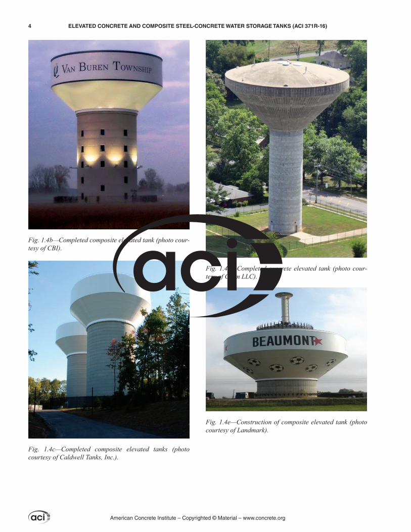
Fig. 1.4c—Completed composite elevated tanks (photo courtesy of Caldwell Tanks, Inc.).
Fig. 1.4d—Completed concrete elevated tank (photo cour-tesy of Crom LLC).
Fig. 1.4e—Construction of composite elevated tank (photo courtesy of Landmark).
Fig. 1.4b—Completed composite elevated tank (photo cour-tesy of CBI).
American Concrete Institute – Copyrighted © Material – www.concrete.org
4 ELEVATED CONCRETE AND COMPOSITE STEEL-CONCRETE WATER STORAGE TANKS (ACI 371R-16)
CHAPTER 2—NOTATION AND DEFINITIONS
2.1—NotationA = areaAc = area of gross section of pedestalAcv = concrete shear area of a section, in.2 (mm2)Af = horizontal projected area of a portion of the struc-
ture where the wind force coefficient Cf and the wind pressure pz are constant, in.2 (mm2)
Ag = gross concrete area of a section, in.2 (mm2)As = area of nonprestressed tension reinforcement, in.2
(mm2)At = cross-sectional area of vessel at mid-depth of waterAw = gross horizontal cross-sectional concrete area of wall,
in.2 (mm2), per unit length of circumference, ft (m)bd = width of a doorway or other opening, in. (mm)bv = equivalent shear wall length not to exceed 0.78dw,
in. (mm)bx = cumulative opening width in a distance of bv, in. (mm)C = buckling parameter for thin metal cylinders that
buckle with diamond-shaped patternCc = spectral acceleration of sloshing liquidCe = eccentricity coefficient that accounts for the resul-
tant of factored axial load being eccentric to the centroid of the pedestal thickness
Ces = snow load exposure factorCf = wind force coefficientCs = seismic response coefficientCsm = modal seismic design coefficient for mode mCvx = seismic distribution factorCvxm = seismic distribution factor of the m-th modecc = clear cover from the nearest surface in tension to the
surface of the flexural torsion reinforcement, in. (mm)D = dead loadDt = tank diameter at the water surface, ft (m)dc = distance from the closest face to the centroid of the
tension reinforcement, in. (mm)dw = mean diameter of concrete pedestal, ft (m)E = combined effect of horizontal and vertical earth-
quake forcesEc = modulus of elasticity for concrete, psi (MPa)Ecr = modulus of elasticity for concrete to allow for
microcracking and creep, psi (MPa)e = eccentricity of the axial wall load, in. (mm)eg = vertical load eccentricity, in. (mm)eo = minimum vertical load eccentricity, in. (mm)F = weight and pressure of stored waterFa = seismic acceleration-based site coefficientFi = portion of the total seismic shear V acting at level i,
kip (kN)Fs = factor of safety against bucklingFv = seismic-velocity-based site coefficientFx = portion of the seismic shear V acting at level x, kip (kN)Fxm = modal force at each level, kip (kN)Fz = wind force acting on tributary area Af, kip (kN)fc = concrete compressive stressfca = average compression stressfc′ = specified compressive strength of concrete, psi (MPa)
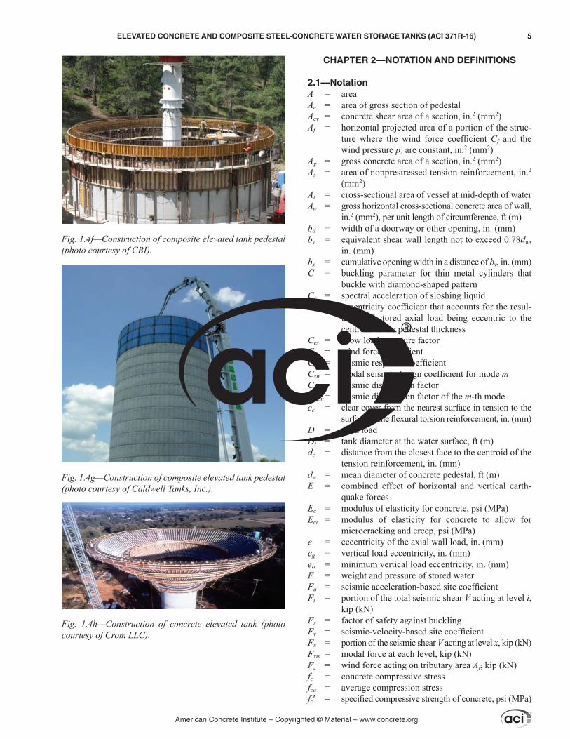
Fig. 1.4f—Construction of composite elevated tank pedestal (photo courtesy of CBI).
Fig. 1.4g—Construction of composite elevated tank pedestal (photo courtesy of Caldwell Tanks, Inc.).
Fig. 1.4h—Construction of concrete elevated tank (photo courtesy of Crom LLC).
American Concrete Institute – Copyrighted © Material – www.concrete.org
ELEVATED CONCRETE AND COMPOSITE STEEL-CONCRETE WATER STORAGE TANKS (ACI 371R-16) 5