reporting 3 continuous emission monitoring system (cem… · emission minimization plan for...
TRANSCRIPT
1. OPERATING PHILOSOPHY ......................................................................................................................... 3 2. REPORTING ................................................................................................................................................... 3 3. CONTINUOUS EMISSION MONITORING SYSTEM (CEM) .................................................................... 4
3.1. Description ............................................................................................................................................... 4 3.2. Operation.................................................................................................................................................. 4 3.3. Critical Criteria ........................................................................................................................................ 5 3.4. Inspections ............................................................................................................................................... 7 3.5. Maintenance ............................................................................................................................................. 8 3.6. Spare Parts ............................................................................................................................................... 8 3.7. Abnormal conditions or malfunction: ...................................................................................................... 8 3.8. Abatement Measures ................................................................................................................................ 9 3.9. Time Frame for Abatement Measures ...................................................................................................... 9
4. ELECTROSTATIC PRECIPITATOR........................................................................................................... 10 4.1. Description ............................................................................................................................................. 10 4.2. ESP Interior Parts ................................................................................................................................... 10 4.3. ESP External Parts ................................................................................................................................. 11 4.4. Operation................................................................................................................................................ 11 4.5. Theory of Operation ............................................................................................................................... 11 4.6. ESP Operation ........................................................................................................................................ 12 4.7. Critical Criteria ...................................................................................................................................... 12 4.8. Inspection ............................................................................................................................................... 13 4.9. Maintenance ........................................................................................................................................... 14 4.10. Spare Parts ......................................................................................................................................... 14 4.11. Abnormal conditions or malfunctions ................................................................................................ 14 4.12. Abatement Measures .......................................................................................................................... 15
5. SELECTIVE NON-CALALYTIC REDUCTION SYSTEM (SNCR) .......................................................... 16 5.1. Description ............................................................................................................................................. 16 5.2. Operation................................................................................................................................................ 16 5.3. Critical Criteria ...................................................................................................................................... 17 5.4. Inspections ............................................................................................................................................. 18 5.5. Maintenance ........................................................................................................................................... 19 5.6. Spare Parts ............................................................................................................................................. 19 5.7. Abnormal conditions or malfunctions .................................................................................................... 19 5.8. Abatement Measures .............................................................................................................................. 19 5.9. Time Frame for Abatement Measures .................................................................................................... 20
6. MECHANICAL DUST COLLECTOR ......................................................................................................... 21 6.1. Description ............................................................................................................................................. 21 6.2. Operation................................................................................................................................................ 21 6.3. Critical Criteria ...................................................................................................................................... 21 6.4. Inspections ............................................................................................................................................. 22 6.5. Maintenance ........................................................................................................................................... 22 6.6. Spare parts .............................................................................................................................................. 22 6.7. Abnormal conditions and malfunctions ................................................................................................. 22 6.8. Abatement measures .............................................................................................................................. 23 6.9. Time Frame for Abatement Measures .................................................................................................... 23
7. BOILER ......................................................................................................................................................... 24 7.1. Description ............................................................................................................................................. 24 7.2. Operation................................................................................................................................................ 25 7.3. Critical Criteria ...................................................................................................................................... 25 7.4. Inspections ............................................................................................................................................. 26 7.5. Maintenance ........................................................................................................................................... 27 7.6. Spare Parts ............................................................................................................................................. 27 7.7. Abnormal conditions, malfunctions, and startup and shutdown ............................................................ 27 7.8. Abatement measures .............................................................................................................................. 28 7.9. Time Frame for Abatement Measures .................................................................................................... 29 8.1 Description ............................................................................................................................................. 30 8.2 Operation................................................................................................................................................ 30 8.3 Critical Criteria ...................................................................................................................................... 30
Emission Minimization Plan for Startup, Shutdown, and Malfunction Hillman Power Company
2
8.4 Inspections ............................................................................................................................................. 31 8.5 Maintenance ........................................................................................................................................... 31 8.6 Abatement Measures .............................................................................................................................. 31
9. MATERIAL HANDLING ............................................................................................................................. 31 9.1 Description ....................................................................................................................................................... 31 Attachments
1. Opacity Monitor
2. Nox Analyzer
3. CO Analyzer
4. O2 Analyzer
5. CEM system Drift Forms
6. CEM spare parts list
7. Boiler startup and natural gas light off
8. Boiler startup wood light off
9. Nox reduction system startup procedures
10. Spare parts for Nox system (SNCR)
11. Spare parts for Mechanical Dust Collector
12. Proximate and ultimate analysis on fuels burned
13. Operators rounds sheet
14. Spare parts list for boiler and auxiliaries
15. Spare parts list for Electrostatic Precipator system
16. Emergency and Special Instructions
17. Plant Shutdown Procedures
Emission Minimization Plan for Startup, Shutdown, and Malfunction Hillman Power Company
3
Hillman Power Company L.L.C. Emission Minimization Plan for Startup, Shutdown, and
Malfunction Abatement Plan (MAP) October 17,
2014
1. OPERATING PHILOSOPHY
The operating philosophy implemented at the Hillman Power Company is to operate the plant
within the emission levels required by the Air Use Permit. To achieve these goals, the boiler will
be operated in the most efficient manner possible, which in turn, will conserve fuel and provide
for complete combustion. Hillman Power Company recognizes that exceedances of limits may
occur which are unavoidable under certain malfunction situations, as well as startup and shutdown
of the boiler and control equipment. The equipment will be operated and maintained in such a
manner to minimize the duration and magnitude of these incidents. The operation of the plant
will be performed utilizing properly trained and experienced operators.
In addition to proper operation, it is equally important to establish inspection and maintenance
procedures that will allow the plant to continue running in an optimum operating condition.
These procedures will include regular scheduled inspections. Properly trained and experienced
plant operators and maintenance personnel will perform the inspections. To ensure that
maintenance will be performed in a timely manner, it is intended to have an inventory of
appropriate spare parts available at the plant for normal scheduled maintenance. The quantity and
type of spare parts selected for inventory will be based on plant operating experience.
2. REPORTING
Operating reports consisting of the Hillman Power Company emission levels and plant operating
data will be submitted quarterly by written report to the Michigan DEQ-AQD district supervisor
within 30 days following the end of the calendar quarter. The quarterly report will include a
detailed analysis of all recording, reporting, and record keeping requirements in compliance with
40 CFR, part 60 and the current Air Use Permit. The quarterly reports will be in a format
exceptible to the department and contain the required information.
In addition to the quarterly reports, notifications will be provided to the DEQ-AQD district
supervisor of any abnormal conditions or malfunctions of process or control equipment that
results in emissions in violation of the Air Use Permit or Rule 912. This notice will be provided
not later than two business days after the startup, shutdown, or discovery of the abnormal
condition or malfunction. Also, within 10 days, a written detailed report including probable
causes, duration of violation, remedial action taken, and the steps which are being taken to prevent
a reoccurrence will be submitted to the DEQ-AQD district supervisor.
All monitoring data for the Hillman Power Company will be kept on file at the plant for a period
of fire years and made available to the DEQ-AQD district supervisor upon request.
Emission Minimization Plan for Startup, Shutdown, and Malfunction Hillman Power Company
4
3. CONTINUOUS EMISSION MONITORING SYSTEM (CEM)
3.1. Description
A continuous emissions monitoring (CEM) system is used to monitor and record the emissions
from Hillman Power Company as required by the current Air Use Permit. The system is a
complete emissions monitoring and data gathering system used to demonstrate compliance with
state and federal air emissions regulations.
Gas emissions and opacity monitoring systems including monitoring, data collection, data storage
and reporting are in accordance with the requirements of the Environmental Protection Agency
(EPA) as stated in 40 CFR Part 60, “Standards of Performance for New Stationary Sources”.
The CEM System monitors opacity, O2, CO, and NOx in the stack at an approved location.
Provisions are made to accept inputs for steam flow and fuel feed rates into the data collection
system.
The monitoring equipment provided comprises a complete system designed to function as a unit.
The CEM system is a direct extractive monitoring system and includes the following items:
a. Probes, transducers, and duct mounted instruments
b. Sample conditioning and extraction equipment
c. Analyzers and monitors
d. Sample tubing and special cable
e. Signal conversion equipment
f. Calibration gases and interconnecting equipment
g. Data collection and storage software
3.2. Operation
The CEM System is operated at all times when the boiler is firing on wood, tire derived fuel
(TDF), other alternative fuels, and natural gas by properly trained experienced operators. The
equipment is operated in accordance with the manufacturer’s recommendations and plant
operating procedures. Monitoring of the CEM system is through the main plant computer (DCS)
Data Control System located in the plants control room. The DCS system is provided with
software to receive and process signals from the analyzers, signal conversions, calculate variables
from the database, signal alarms, and store and retrieve data.
The DCS system provides fault monitoring to detect equipment malfunction. Outputs are
provided to alarm system malfunctions as sensed by the fault monitors supplied as part of the
analyzers and the DCS system. The DCS system alarms and logs the following:
CO emissions high and low
Opacity emissions high and low
Emission Minimization Plan for Startup, Shutdown, and Malfunction Hillman Power Company
5
O2 concentration high and low
NOx emissions high and low
SO2 emissions high and low
The DCS system is a redundant system, failure of one component will not result in the loss of any
previously stored data within 24 hours. The DCS system is designed to sustain memory in the
event of a power supply failure and is supplied with an internal clock to maintain correct time and
date during power failure.
Hourly and daily reports can be generated at the operator’s request. The dates and times are
included in the reports when the report is requested. The report uses the most up-to-date
information from the data base of emissions data stored in the computer.
Reports display hourly emissions averages, rolling averages, daily averages, status logs, steam
flow, fuel feed rate, 6 minute averages for opacity, and values of emission products as ppmd, #/hr,
and other data as required by the specified regulatory agencies.
Operator generated logs compiled from DCS trend logs are also kept on file. These logs
demonstrated compliance or noncompliance, give reason codes for noncompliance, and contain a
comment section for operation action taken.
3.3. Critical Criteria
The CEM System is operated in a manner that will provide accurate monitoring, recording, and
reporting of Hillman Power Company’s emissions limitation as specified in the plants current Air
Use Permit. The CEM System is operated to monitor the following critical criteria:
Opacity
a. The Opacity monitor is designed to accurately monitor and record the flue gas opacity.
Visible emissions from the boiler are not to exceed the specified limits set in the air
use permit.
b. The opacity monitor optical head and retro reflector alignment will be properly
aligned when the angle of projection from the optical head is within two degrees and
the angle of view from the retro reflector is within two degrees. Completed as needed.
c. The allowable angle of alignment drift will be within 0.5 degrees.
d. The optical head light source is a super wide band diode.
e. A blower is provided for the optical head and retro reflector for gas purging of the
assemblies. The blowers are designed to provide 60 inches water column of static
pressure and are fitted with an inlet filter and particulate bowl.
f. A copy of the calibration procedures are add as attachment #1.
g. A calibration check instrument is at the facility and is used whenever necessary to
verify accuracy, and calibrate the instrument. The calibration check instrument is also
Emission Minimization Plan for Startup, Shutdown, and Malfunction Hillman Power Company
6
used for the Relative Accuracy Test Audit by the vendor contracted to perform the
testing.
h. The opacity monitor is automatically calibrated daily and a RATA is performed
annually.
NOx
a. The NOx analyzer is designed to accurately monitor and record the NOx emission
levels from the boiler. The NOx emission rate from the boiler will not exceed the
limits of the current air use permit.
b. The NOx calibration gas cylinder will contain gas of at least 80% to 100 % of the
instrument range.
c. The NOx analyzer sensitivity will be a 0.5-ppb.
d. The NOx analyzer range will be 0 - 500 ppm.
e. The NOx analyzer accuracy will be 2% of full scale.
f. The NOx analyzer calibration drift will be 1% in 24 hours.
g. The purge air supply for the NOx sample will be at 120 psi and at a flow rate of 6
liters per minute.
h. The calibration gas supply for the NOx sample will be at a flow rate of 8 liters per
minute.
i. A copy of the calibration procedures is supplied as attachment #2.
j. The NOx analyzer is run through, a daily calibration of the zero and span, a quarterly
Cylinder Gas Audit, and an annual RATA test.
SO2
a. The SO2 analyzer is designed to accurately monitor and record the SO2 emission
levels from the boiler. The SO2 emission rate from the boiler will not exceed the
limits of the current air use permit.
b. The SO2 calibration gas cylinder will contain gas of at least 80% to 100 % of the
instrument range.
c. The So2 analyzer sensitivity will be a 0.5-ppb.
d. The SO2 analyzer range will be 0 - 500 ppm.
e. The SO2 analyzer accuracy will be 2% of full scale.
f. The SO2 analyzer calibration drift will be 1% in 24 hours.
g. The purge air supply for the SO2 sample will be at 120 psi and at a flow rate of 6 liters
per minute.
h. The calibration gas supply for the SO2 sample will be at a flow rate of 8 liters per
minute.
i. A copy of the calibration procedures is supplied as attachment #2.
j. The SO2 analyzer is run through, a daily calibration of the zero and span, a quarterly
Cylinder Gas Audit, and an annual RATA test.
Emission Minimization Plan for Startup, Shutdown, and Malfunction Hillman Power Company
7
Carbon Monoxide
a. The CO analyzer is designed to accurately monitor and record the CO emission levels
from the boiler. The CO emission rate from the boiler is not to exceed the plants
current air use permit based on a 24-hour daily average.
b. The calibration gas cylinder will contain CO gas at 80% to 100% of instrument range.
c. The CO analyzer sensitivity is 0.1 ppm.
d. The CO analyzer range is 0 to 1000 ppm.
e. The CO accuracy will be 2 % of full scale.
f. The CO analyzer calibration drift will be 3% in 24 hours.
g. The purge air supply for the CO sample will be 120 psi at 8 liters per minute.
h. The CO calibration gas supply for the CO sample will be at a flow rate of 3.5 liters per
minute.
i. A copy of the calibration procedures is added as attachment #3.
j. The CO analyzer is run through a daily calibration of the zero and span, a quarterly
Cylinder Gas Audit, and an annual RATA test.
Oxygen (O2)
a. The O2 analyzer is designed to accurately monitor and record the levels of O2 at the
stack gas sample point. The predicted levels of O2 are in the range of 5% to 6%.
b. The O2 calibration gas cylinders will contain O2 gas at 2% and 18% by volume.
c. The O2 analyzer sensitivity will be 0.1%.
d. The O2 analyzer range will be 0 - 25 %.
e. The O2 analyzer accuracy will be 0.1% of full scale.
f. The O2 analyzer calibration drift will be 2.5% in 24 hour.
g. The reference air supply for the O2 sample is 2 SCFH.
h. The O2 analyzer calibration gas supply for the O2 sample is at a flow rate of 10 liters
per minute.
i. A copy of the calibration procedure is added as attachment #4.
3.4. Inspections
a. Daily inspections are performed on the CEM equipment to ensure that the equipment
is
operating properly. Inspection form # 1 is used see attachment # 5
b. Quarterly cleaning is done on the equipment if there is enough monitor equipment
down
time left for the quarter. Work orders (log # 5) are used for the cleaning and
inspection
forms see attachment #5
c. Annual cleaning and inspection is done on our annual outage for maintenance and
Emission Minimization Plan for Startup, Shutdown, and Malfunction Hillman Power Company
8
repair. Work orders (log # 5) are used for the cleaning and inspection forms see
attachment # 5
Daily, quarterly, and annual inspections are performed on the CEM equipment to ensure that the
equipment is operating properly and to observe various changes that may indicate a potential
malfunction. If the CEM system fails to pass any inspection immediate action is taken to correct
the malfunction or abnormal condition. Copies of the inspection forms are added as attachment
#5
3.5. Maintenance
Maintenance on the CEM equipment is performed in accordance with the manufacturer’s
recommendations. Normal maintenance is performed during the daily and quarterly inspections
with the replacement of worn parts that do not meet the manufacturer’s specification tolerances.
Other maintenance is performed to either replace or rebuild various pieces of equipment when a
malfunction occurs.
3.6. Spare Parts
Spare parts are purchased and stored in inventory based on plant operating experience. A copy of
the spare parts inventory is included as attachment #6.
3.7. Abnormal conditions or malfunction:
Abnormal conditions or malfunctions of the equipment include, but are not limited to, the
following equipment status which result in emissions or operations outside the permit
requirements:
a. CO analyzer failure
b. NOx analyzer failure
c. Opacity analyzer failure
d. O2 analyzer failure
e. Failure of extractive system
f. Failure of cabinet heater or air conditioner
g. Failure of electronic transmission system between analyzer’s and DCS system
h. Failure of DCS printer
i. Failure of purge air system
Emission Minimization Plan for Startup, Shutdown, and Malfunction Hillman Power Company
9
3.8. Abatement Measures
In the event that a malfunction should occur to the CEM equipment that affects monitoring,
recording, or reporting of the plant emissions, specific action will be taken to correct the
equipment malfunction. Whenever needed the use of overtime, off-shift labor, outside consultants
or contractors, where reasonable to minimize the duration of the malfunction or excess emissions
will be used. This action in cooperation with the DEQ-AQD district supervisor will be taken and
one or more of the following steps:
a. Based on stable operation of the boiler and being in compliance with the required
emission levels at the time of the malfunction, continue to run the boiler at a stable
rate of operation and repair the CEM equipment as soon as possible.
b. Should it be determined that equipment replacement is required in lieu of repairs,
continue to run the boiler at a stable rate of operation and replace the equipment as
soon as possible.
c. Should it be determined that replacement of equipment is going to take an excessive
length of time, continue to run the boiler at a stable rate of operation and arrange for
rental of CEM equipment in the interim period.
d. Should it be determined that rental of CEM equipment is not possible, continue to run
the boiler in a manner where extensive operating experience has demonstrated that the
plant always complied with the permit emission levels.
e. Plant shutdown.
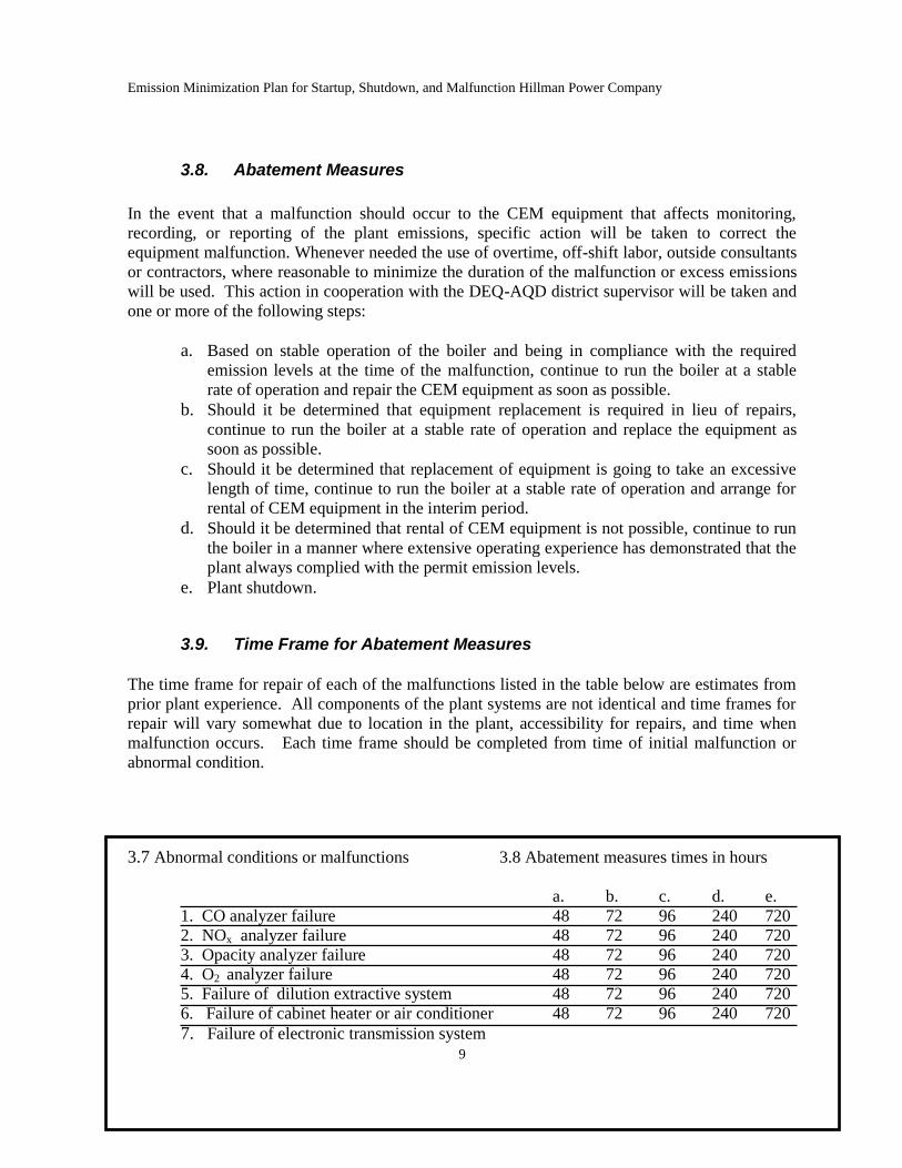
3.9. Time Frame for Abatement Measures
The time frame for repair of each of the malfunctions listed in the table below are estimates from
prior plant experience. All components of the plant systems are not identical and time frames for
repair will vary somewhat due to location in the plant, accessibility for repairs, and time when
malfunction occurs. Each time frame should be completed from time of initial malfunction or
abnormal condition.
3.7 Abnormal conditions or malfunctions 3.8 Abatement measures times in hours
a. b. c. d. e.
1. CO analyzer failure 48 72 96 240 720
2. NOx analyzer failure 48 72 96 240 720
3. Opacity analyzer failure 48 72 96 240 720
4. O2 analyzer failure 48 72 96 240 720
5. Failure of dilution extractive system 48 72 96 240 720
6. Failure of cabinet heater or air conditioner 48 72 96 240 720
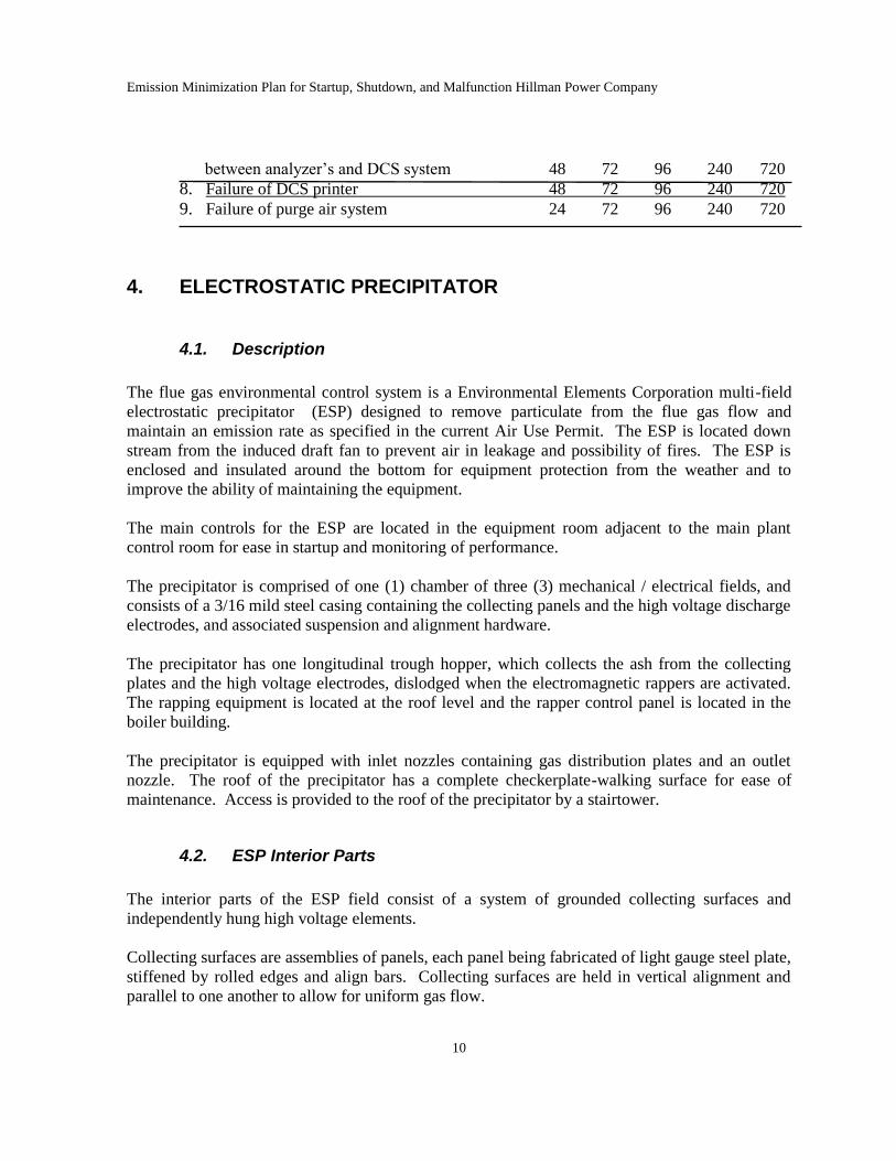
7. Failure of electronic transmission system
Emission Minimization Plan for Startup, Shutdown, and Malfunction Hillman Power Company
10
between analyzer’s and DCS system 48 72 96 240 720
8. Failure of DCS printer 48 72 96 240 720
9. Failure of purge air system 24 72 96 240 720
4. ELECTROSTATIC PRECIPITATOR
4.1. Description
The flue gas environmental control system is a Environmental Elements Corporation multi-field
electrostatic precipitator (ESP) designed to remove particulate from the flue gas flow and
maintain an emission rate as specified in the current Air Use Permit. The ESP is located down
stream from the induced draft fan to prevent air in leakage and possibility of fires. The ESP is
enclosed and insulated around the bottom for equipment protection from the weather and to
improve the ability of maintaining the equipment.
The main controls for the ESP are located in the equipment room adjacent to the main plant
control room for ease in startup and monitoring of performance.
The precipitator is comprised of one (1) chamber of three (3) mechanical / electrical fields, and
consists of a 3/16 mild steel casing containing the collecting panels and the high voltage discharge
electrodes, and associated suspension and alignment hardware.
The precipitator has one longitudinal trough hopper, which collects the ash from the collecting
plates and the high voltage electrodes, dislodged when the electromagnetic rappers are activated.
The rapping equipment is located at the roof level and the rapper control panel is located in the
boiler building.
The precipitator is equipped with inlet nozzles containing gas distribution plates and an outlet
nozzle. The roof of the precipitator has a complete checkerplate-walking surface for ease of
maintenance. Access is provided to the roof of the precipitator by a stairtower.
4.2. ESP Interior Parts
The interior parts of the ESP field consist of a system of grounded collecting surfaces and
independently hung high voltage elements.
Collecting surfaces are assemblies of panels, each panel being fabricated of light gauge steel plate,
stiffened by rolled edges and align bars. Collecting surfaces are held in vertical alignment and
parallel to one another to allow for uniform gas flow.
Emission Minimization Plan for Startup, Shutdown, and Malfunction Hillman Power Company
11
High voltage discharge electrodes are a rigid mast type of rolled construction, hung from a
framework of channels and angles braced and tied to prevent horizontal movement. Each mast is
bolted in place at the upper end and lower end.
The masts are shrouded at the top and lower end to prevent electrical sparking. An alignment
frame at the lower end of the elements is designed to maintain the elements in proper vertical and
horizontal alignment.
The spaces between parallel collecting surfaces are called gas passages, and the high voltage
discharge electrodes are positioned in these spaces symmetrical with collecting surfaces.
The high voltage frame in each field is supported at four (4) points by insulators mounted on the
precipitator casing cover and housed in steel compartments. These support insulators provide
electrical insulation between the high voltage frame and the grounded structure.
4.3. ESP External Parts
The high voltage for the discharge systems is supplied by transformer-rectifier sets located on the
ESP roof. These units are connected to the high voltage elements through high voltage lines. The
high voltage lines and high voltage support insulators are enclosed in bus ducts above the ESP
roof level. Extremely accurate power regulation to each high voltage system is provided by
automatic control.
All ESP operating control and indicator panels, power distribution and automatic voltage control
units are located in the equipment room adjacent to the plants main control room.
The ESP also has a series of ash augers, rotary valve, and mixer system to handle the ash to the
ash bay for storage until it is removed from the site.
The ESP ash system is equipped with motion detection devices that will alarm the Operator Tech
in the plants main control room of any interruption in the system. The mixer system also uses
water for temperature and dust control.
4.4. Operation
Properly trained operators who operate the equipment in accordance with the manufacturer’s
recommendations and plant operating procedures operate the ESP.
4.5. Theory of Operation
Operation of the ESP depends upon creation of an electrostatic field to electrically charge dust
particles in the gas stream as it passes through the ESP.
Emission Minimization Plan for Startup, Shutdown, and Malfunction Hillman Power Company
12
The electrostatic field is established by stepping up low voltage alternating current with a
transformer, and changing the resulting high voltage alternating current with a rectifier to high
voltage direct current. The rectified current is then delivered to a system of mast electrodes
uniformly spaced between collecting surfaces. The mast electrodes create the electrostatic field
within spaces between the collecting surfaces.
The dust particles in the gas stream are charged as they pass through the electrostatic field. Most
particles are charged negatively, or opposite in polarity to that of the collecting surfaces, and
therefore are attracted to these surfaces and adhere to them until removed. The remaining
particles are attracted to the mast electrodes. This collected material is periodically removed by a
system of rappers which strike the surfaces a sharp blow, breaking loose the collected material,
which then falls by gravity into the precipitator hoppers.
The polarity of the transformer-rectifier high voltage output is always negative at the voltage
necessary for highest ESP operating efficiency.
The precipitator may be operated either on automatic or manual voltage control. On automatic
control, the controller varies the voltage to the ESP as required to maintain optimum removal
efficiency under varying inlet gas and dust conditions. On manual control, proper ESP operating
voltage is obtained by adjusting voltage until only occasional sparking or shorting between high
tension electrodes and the collecting surfaces is reflected by the spark-rate meter.
4.6. ESP Operation
The main controls for the ESP are located in the plant equipment room and control room, they
will perform the following specific functions:
a. Automatic voltage regulation to each of the transformer/rectifiers associated with
the three (3) fields.
b. Control the operation of the Insulator Compartment Pressurization System, which
provides a positive pressure to prevent dust from entering the compartment.
c. Control the operation of the rappers system on the collecting surfaces, discharge
electrodes, and the ESP inlet distribution plates.
d. Monitor high ash level in the ESP ash hoppers.
e. Control power supply to the ESP through the key interlock system on the ESP
access doors.
f. Control ESP ash auger and mixing system.
g. Ash auger motion detection system.
h. Monitor the ESP ash hopper electric heating system.
4.7. Critical Criteria
The operational parameters for the critical criteria are not requirements of the air use permit but
are requirements for safe operating conditions. The operation of the ESP controls the final
Emission Minimization Plan for Startup, Shutdown, and Malfunction Hillman Power Company
13
particulate emissions from the plant. The ESP operates in a manner to satisfy the following
critical criteria:
Particulate
a. Inlet dust loading to the ESP not to exceed 1.7 gr./DSCF. As design specifications.
b. Flue gas temperature entering the ESP not to exceed 360 degrees F. As design specifications.
c. Flue gas moisture content entering the ESP not to be greater than 29%. As design
specifications.
d. Particulate emissions from the ESP outlet shall not exceed the Air Use Permit limits.
Monitored and recorded by the CEM
e. Visible emissions from the ESP not to exceed the limitations of the Air Use Permit. Monitored
and recorded by the CEM
A copy of the plant startup procedures is added as attachment #8 which includes the
startup procedures for the ESP.
4.8. Inspection
Daily inspections are performed on the ESP in accordance with the manufacturer’s
recommendations and plant operating experience to ensure that the equipment is operating
properly and to observe various changes that may indicate potential malfunction. The inspections
performed each day are as follows: See attached plant log sheets section 13
a. Spark rate on each of the three fields average from 0 to 240 sparks per min. Log # 2
b. Voltage on each of the three fields maximum is 55 KV Log # 2
c. Amperage on each of the three fields. Log # 2
d. Transformer oil temperature on each field maximum is 550 C. Log # 3
e. Transformer oil Pressure on each field. Log # 3
f. Rappers operating properly. Monitored by the DCS and operators
g. Ash removal system operating properly. Log # 4
Weekly inspection items:
a. Remove dust and foreign matter from electrical equipment. Log #7
b. Check signal lights for proper operation. Log #7
c. Check rapper alignment. Log #7
d. Check rapper boots for cracks and wear. Log #7
e. Check tightness of belts on penthouse fan. Log #7
f. Grease penthouse blower fan and motor. Log #7
g. Check precipator rotary valve and lubricate. Log #7
h. Inspect and lubricate precipitator ash system bearings. Log #7
i. Check precipator auger gear boxes for unusual sounds, vibrations, and grease. Log #7
Emission Minimization Plan for Startup, Shutdown, and Malfunction Hillman Power Company
14
Annual inspections items:
a. Clean insulators in the high voltage insulator compartment, as well as all other
insulators.
b. Thoroughly inspect the interior of the ESP and make necessary adjustments or repairs.
Give particular attention to the high voltage electrodes, each of which should be centered
between the collecting surfaces. Misalignment of even a single unit reduces the electrical
clearances between high voltage electrodes and collecting surfaces, resulting in a marked
reduction of collecting efficiency. Misaligned electrodes should be removed or replaced
as required.
c. Disassemble electric rappers and inspect the high voltage system rapper shaft ceramic
material for deterioration or cracking.
d. Test the insulating fluid in each transformer for dielectric strength according to the
appropriate American Society of Testing Materials Code. See plant work orders Log #5
section 13.
See plant work orders.
4.9. Maintenance
Maintenance on the ESP is performed in accordance with the manufacturer’s recommendations
and previous plant experience. Normal maintenance is performed during the annual inspection
with the replacement of worn parts that do not meet the manufacturer’s specification tolerances.
Other maintenance is performed to either replace of rebuild various pieces of equipment should a
malfunction occur or force the shut down of the boiler.
4.10. Spare Parts
Spare parts will be purchased and stored in inventory based on the manufacturer’s
recommendations and plant operating experience. The expected spare parts list for the ESP is
added as attachment 15#.
4.11. Abnormal conditions or malfunctions
Abnormal conditions or malfunctions of the equipment include, but are not limited to, the
following equipment status which result in emissions or operations outside the permit
requirements:
a. ESP ash and mixer system
b. Penthouse pressurization system
c. Transformers/rectifier system
Emission Minimization Plan for Startup, Shutdown, and Malfunction Hillman Power Company
15
d. ESP high voltage insulators
e. ESP rapper system
f. Startup and shutdown of plant
g. Rigitrode/plate collection system
4.12. Abatement Measures
In the event that a malfunction should occur to the ESP equipment that affects or controls the
plant emissions and causes the plant to exceed the permitted levels, specific action will be taken to
bring the plant back into compliance. Whenever needed the use of overtime, off-shift labor,
outside consultants or contractors, where reasonable to minimize the duration of the malfunction
or excess emissions will be used. This action, in cooperation with the DEQ-AQD district
supervisor will be taken and either one or more of the following steps:
a. Continue to run the malfunctioned ESP equipment at lower loads or fewer electrical
fields as long as the plant emissions are in compliance. This may or may not require
the boiler to run at reduced loads.
b. Correct the malfunctioned equipment by taking it out of service for repairs. It may be
possible to run the ESP and boiler at reduced loads and be in compliance with
emissions when the malfunctioned equipment is out of service for repairs.
c. Continue to run the boiler and repair the equipment, if the estimated repair would
create less total emission than a normal shutdown and startup. Emissions may exceed
the permit limits for certain periods of time during boiler startup and shutdown. This
situation may be unavoidable and is addressed in the emission minimization plan
during startup and shutdown (see Section 7).
d. Correct the malfunctioned equipment by shutting down the ESP and repair the
equipment. Shutting down the ESP will also require shutting down the boiler, which
in turn will cease all plant emissions.
Time Frame for Abatement Measures
The time frame for repair of each of the malfunctions listed in the table below are estimates from
prior plant experience. All components of the plant systems are not identical and time frames for
repair will vary somewhat due to location in the plant, accessibility for repairs, and time when
malfunction occurs. Each time frame should be completed from time of initial malfunction or
abnormal condition.
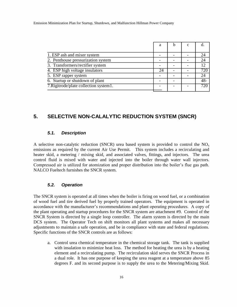
4.11Abnormal conditions or malfunctions 4.12 Abatement measures times in hours
Emission Minimization Plan for Startup, Shutdown, and Malfunction Hillman Power Company
16
a b c d.
1. ESP ash and mixer system - - - 24
2. Penthouse pressurization system - - - 24
3. Transformers/rectifier system - - - 12
4. ESP high voltage insulators 24 - - 720
5. ESP rapper system - - - 24
6. Startup or shutdown of plant - - 48-
7.Rigitrode/plate collection system1. - - - 720
5. SELECTIVE NON-CALALYTIC REDUCTION SYSTEM (SNCR)
5.1. Description
A selective non-catalytic reduction (SNCR) urea based system is provided to control the NOx
emissions as required by the current Air Use Permit. This system includes a recirculating and
heater skid, a metering / mixing skid, and associated valves, fittings, and injectors. The urea
control fluid is mixed with water and injected into the boiler through water wall injectors.
Compressed air is utilized for atomization and proper distribution into the boiler’s flue gas path.
NALCO Fueltech furnishes the SNCR system.
5.2. Operation
The SNCR system is operated at all times when the boiler is firing on wood fuel, or a combination
of wood fuel and tire derived fuel by properly trained operators. The equipment is operated in
accordance with the manufacturer’s recommendations and plant operating procedures. A copy of
the plant operating and startup procedures for the SNCR system are attachment #9. Control of the
SNCR System is directed by a single loop controller. The alarm system is directed by the main
DCS system. The Operator Tech on shift monitors all plant systems and makes all necessary
adjustments to maintain a safe operation, and be in compliance with state and federal regulations.
Specific functions of the SNCR controls are as follows:
a. Control urea chemical temperature in the chemical storage tank. The tank is supplied
with insulation to minimize heat loss. The method for heating the urea is by a heating
element and a recirculating pump. The recirculation skid serves the SNCR Process in
a dual role. It has one purpose of keeping the urea reagent at a temperature above 85
degrees F. and its second purpose is to supply the urea to the Metering/Mixing Skid.
Emission Minimization Plan for Startup, Shutdown, and Malfunction Hillman Power Company
17
The skid consists of dual redundant centrifugal pumps, one electric in-line heater, one
self-contained control panel, and all associated stainless steel piping and valving.
b. The metering mixing skid is used to supply urea to the (3) injector wands mounted
on the upper boiler walls. The unit includes two sets of full flow duplex metering
pumps and gear pumps for water/chemical mixing and pressure boost, respectively.
The skid contains a pressure control loop consisting of a pneumatic valve and a
pressure transmitter system wired into the single loop controller for discharge pressure
control. In addition the module contains all necessary motor operated ball valves,
manual ball valves, check valves, pressure switches, flow switches, and stainless steel
piping to make it a self-contained pumping system.
c. The SNCR also contains an air pressure regulator system which is used to control the
atomizing air pressure at the injectors.
d. The injectors consist of an atomizing chamber in which the air and urea first meet.
Air is required for atomizing the urea and cooling when the injectors are off-line and
not retracted from the boiler.
5.3. Critical Criteria
The SNCR System is operated in a manner that will control the plant’s NOx emissions in
compliance with the current Air Use Permit. The SNCR System is operated to maintain the
following critical criteria
NOx
a. The SNCR System provides the proper urea and water mixture to the injectors to
maintain plant NOx emissions at the current air use permit limits. This level of NOx
emissions represents a reduction of approximately 20 percent of the NOx level
received from the boiler.
b. In order to achieve the above reduction in NOx emissions the urea is injected and
atomized through injectors installed in the boiler walls in a location where the furnace
temperature averages 1800 degrees F.
c. Proper flow and mixing of the urea chemical is best controlled when the chemical
temperature is maintained at greater than 70 degrees F. log #4 section 13
d. Compressed air at a pressure of 80 psig is provided for atomization of the urea
chemical into the boiler. Log #3 section 13
Emission Minimization Plan for Startup, Shutdown, and Malfunction Hillman Power Company
18
e. Service water for urea dilution is provided at a pressure of 60 psig to the metering
mixing skid. Log #3 section 13
f. The NOx emissions are monitored by the CEM equipment and recorded by the plants
DCS system as required by the current Air Use Permit.
CO
a. The SNCR System by injecting urea chemical for NOx reduction will contribute to the
level of CO emissions. However the SNCR System is designed to be in compliance
with the Air Use Permit.
5.4. Inspections
Inspections are performed on the SNCR system every four hours to insure that the equipment is
operating properly and to observe any changes that may indicate potential malfunction of the
equipment. The inspections performed are as follows: see log sheets section 13
a. Observe the level in the urea-mixing tank, operating range is from 200 to 750 gallons.
. Log #3
b. Observe the recirculation skid, heater, pump, and discharge pressure. The discharge
pressure during normal operation averages 20 psig. Log #4
c. Observe the metering/mixing skid, pumps, and pressure control system. Log #3
d. Observe the air pressure to the injectors for proper atomization and cooling.
Atomization air pressure during normal operations averages 35 psig. Log #3
e. Observe the service water supply to the metering/mixing skid for proper water
pressure. City water pressure averages 60 psig. Log #3
Through the process of normal operation other operating parameters are continuously observed in
the control room including NOx emission levels. Maintaining the plant emissions at proper levels
provides an additional means of inspection that assures the plant operators that the SNCR system
is operating properly.
Annual inspections are performed on the SNCR equipment to ensure that the equipment is in
proper operating condition. This inspection includes the shutting down of the equipment during a
scheduled plant shutdown and removal of various parts for close inspections. Annual inspections
and tear down may include the following equipment: See plant work orders Log #5 section 13.
a. Piping Injectors
b. Pumps
Emission Minimization Plan for Startup, Shutdown, and Malfunction Hillman Power Company
19
c. Heater system
d. Check valves
5.5. Maintenance
Maintenance on the SNCR System is performed in accordance with the manufacturer’s
recommendations and previous plant experience. Normal maintenance is performed during the
annual inspection with the replacement of worn parts that do not meet the manufacturer’s
specification tolerances. Other maintenance is performed to either replace or rebuild various
pieces of equipment should a malfunction occur and force the shutdown of individual pieces of
equipment. Due to the redundancy of many pieces of equipment, a malfunction of rotating
equipment will not shut the SNCR System down.
5.6. Spare Parts
Spare parts are purchased and stored in inventory based on manufacturer’s recommendations and
plant operating experience. The spare parts for the SNCR equipment is added as attachment #10.
5.7. Abnormal conditions or malfunctions
Abnormal conditions or malfunctions of the equipment include, but are not limited to, the
following equipment status which result in emissions or operations outside the permit
requirements:
a. Heater system failure
b. Pressure control system failure
c. Single loop controller failure
d. Injector failure
e. Failure of air supply for atomization and cooling
f. Loss of dilution water supply
g. System temperature control of solubility of solution
h. Flue gas temperature control
i. Nitrogen content in alternative fuels
j. Failure of motor operated control valves
k. Failure of pumps, piping, or check valves
5.8. Abatement Measures
In the event that a malfunction should occur to the SNCR equipment that affects or controls the
plant emissions, specific action will be taken to correct the equipment malfunction.
Whenever needed the use of overtime, off-shift labor, outside consultants or contractors, where
reasonable to minimize the duration of the malfunction or excess emissions will be used. This
action in cooperation with the DEQ-AQD district supervisor will be taken, and one or more of the
following steps:
Emission Minimization Plan for Startup, Shutdown, and Malfunction Hillman Power Company
20
a. Continue to run the malfunctioned equipment as long as the plant emissions are in
compliance. This may or may not require the boiler to run at reduced loads.
b. Correct the malfunctioned equipment by taking it out of service for repairs. In some
cases, it will be possible to run the boiler at either full load or reduced load and be in
compliance with emissions when the malfunctioned SNCR equipment is out or service
for repairs.
c. Continue to run the boiler and repair the equipment, if the repair takes less time than
the time required for a normal boiler shutdown and startup. Emissions may exceed the
permit limits for certain periods of time during boiler startup and shutdown. This
situation may be unavoidable and is addressed in the emission minimization plan
during startup and shutdown (see Section 7)
.
d. Correct the malfunctioned equipment by shutting down the SNCR system and
boiler to repair the equipment. Shutting down the boiler will cease all plant
emissions.
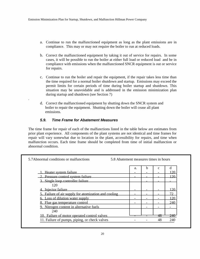
5.9. Time Frame for Abatement Measures
The time frame for repair of each of the malfunctions listed in the table below are estimates from
prior plant experience. All components of the plant systems are not identical and time frames for
repair will vary somewhat due to location in the plant, accessibility for repairs, and time when
malfunction occurs. Each time frame should be completed from time of initial malfunction or
abnormal condition.
5.7Abnormal conditions or malfunctions 5.8 Abatement measures times in hours
a. b c d
1. Heater system failure - - - 120
2. Pressure control system failure - - - 120
3. Single loop controller failure - - -
120
4. Injector failure - - - 120
5. Failure of air supply for atomization and cooling - - - 72
6. Loss of dilution water supply - - - 120
8. Flue gas temperature control - - - 240
9. Nitrogen content in alternative fuels - - -
240
10. Failure of motor operated control valves - - 48 240
11. Failure of pumps, piping, or check valves - - 48 240
Emission Minimization Plan for Startup, Shutdown, and Malfunction Hillman Power Company
21
6. MECHANICAL DUST COLLECTOR
6.1. Description
A Joy Manufacturing multi-clone mechanical dust collector is provided in the flue gas ductwork
exiting the boiler. The multi-clone mechanical dust collector will remove the heavier particles of
fly ash from the flue gas steam prior to the flue gas passing through the induced draft fan and to
the electrostatic precipitator. The mechanical dust collector is furnished by Joy Manufacturing
Corporation.
The mechanical dust collector does not have moving parts and is fitted with the following fixed
devices for removal of dust particles, char, and sand.
A series of collector tubes consisting of inlet and outlet tubes.
The collector tubes are contained within a dust collector housing where the flue gas enters and
exits the mechanical dust collector. Two ash hoppers are attached to the housing to collect the ash
removed from the gas stream by the collector tubes.
6.2. Operation
The mechanical dust collector is operated at all times when the boiler is operating. In as much as
the mechanical dust collector has no moving parts, it relies on centrifugal force created by the
collector tubes for removal of dust particles, char and sand from the flue gas stream. This
material is then collected in the ash hoppers below the collector tube housing and removed by
means of the ash handling system.
Controls for the mechanical dust collector operate rotary valves and an ash removal system on the
outlets of the ash hoppers. This equipment handles the material removed by the multi-clone
collector tubes.
6.3. Critical Criteria
The operation of the mechanical dust collector assist in controlling the plant’s particulate
emissions. The mechanical dust collector is operated in a manner to satisfy the following critical
criteria.
Particulate
Emission Minimization Plan for Startup, Shutdown, and Malfunction Hillman Power Company
22
Inlet dust loading to the collectors per cubic feet of flue gas flow.
Flue gas temperature of approximately 350 degrees F. at collectors.
6.4. Inspections
Daily inspections are performed on the mechanical dust collector to ensure that the equipment is
operating properly and to observe various changes that may indicate potential malfunction. The
inspections to be performed each day are as follows: see log sheets section 13
a. Observe the operation of the system. Log #4
b. Observe that the ash removal system is operating properly. Log #4
c. Operator Tech from the DCS system monitor the drafts and temperature on the
system continuously. Under normal conditions the dust collector draft averages -9 inches
of water and operates at an average temperature of 340o F.
Annual inspections are performed on the mechanical dust collector to ensure that the equipment is
in proper operating condition. This inspection includes the shutting down of the boiler and
internal inspection of the multi-clone collector tubes. Log #5
Due to the abrasive nature of the sand and unburned char being collected in the mechanical dust
collector, the multi-clone collector tubes will erode away and need to be replaced periodically.
The rotary air lock valves and external ash removal system are to be inspected during the annual
outage.
6.5. Maintenance
Maintenance on the mechanical dust collector is performed in accordance with the manufacture’s
recommendations and plant operating experience. Normal maintenance is performed during the
annual inspection with the replacement of worn parts that do not meet the manufacturer’s
specification tolerances. Other maintenance will be performed to either replace or rebuild
various pieces of equipment should a malfunction occur and force the shut down of the boiler.
6.6. Spare parts
Spare parts are purchased and stored in inventory based on manufacturer’s recommendations and
plant operating experience. The spare parts list for the mechanical dust collector is included as
attachment #11.
6.7. Abnormal conditions and malfunctions
Abnormal conditions or malfunctions of the equipment include, but are not limited to, the
following equipment status which result in emissions or operations outside the permit
requirements:
Emission Minimization Plan for Startup, Shutdown, and Malfunction Hillman Power Company
23
a. Rotary air lock valve failure
b. Ash removal system failure
c. Ash reinjection system failure
d. Centrifugal turning vanes or separator tube failure.
e. Tube sheet failure.
6.8. Abatement measures
In the event that a malfunction should occur to mechanical dust collector equipment that affects
the control of the plant emissions and causes the plant to exceed the permitted levels, specific
action will be taken to bring the plant back into compliance. Whenever needed the use of
overtime, off-shift labor, outside consultants or contractors, where reasonable to minimize the
duration of the malfunction or excess emissions will be used. This action in cooperation with the
DEQ-AQD district supervisor will be taken and either one or more of the following steps:
a. Continue to run the malfunctioned equipment at lower loads as long as the plant
emissions are in compliance. This may or may not require the boiler to run at reduced
loads.
b. Continue to run the boiler and repair the equipment, if the estimated repair would
create less total emission than a normal shutdown and startup. Emissions may
exceed the permit limits for certain periods of time during boiler startup and
shutdown. This situation may be unavoidable and is addressed in the emission
minimization plan during startup and shutdown (see Section 7).
c. Correct the malfunctioned equipment by shutting down the boiler and repair the
equipment. Shutting down the boiler will cease all plant operations.
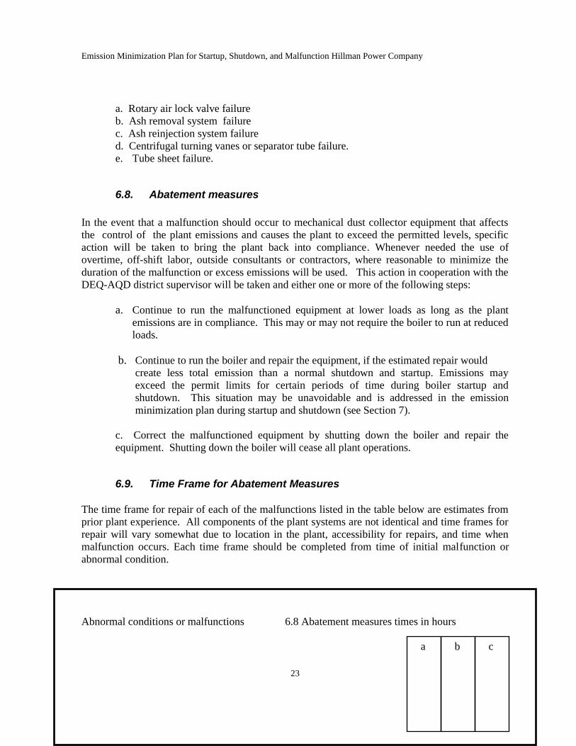
6.9. Time Frame for Abatement Measures
The time frame for repair of each of the malfunctions listed in the table below are estimates from
prior plant experience. All components of the plant systems are not identical and time frames for
repair will vary somewhat due to location in the plant, accessibility for repairs, and time when
malfunction occurs. Each time frame should be completed from time of initial malfunction or
abnormal condition.
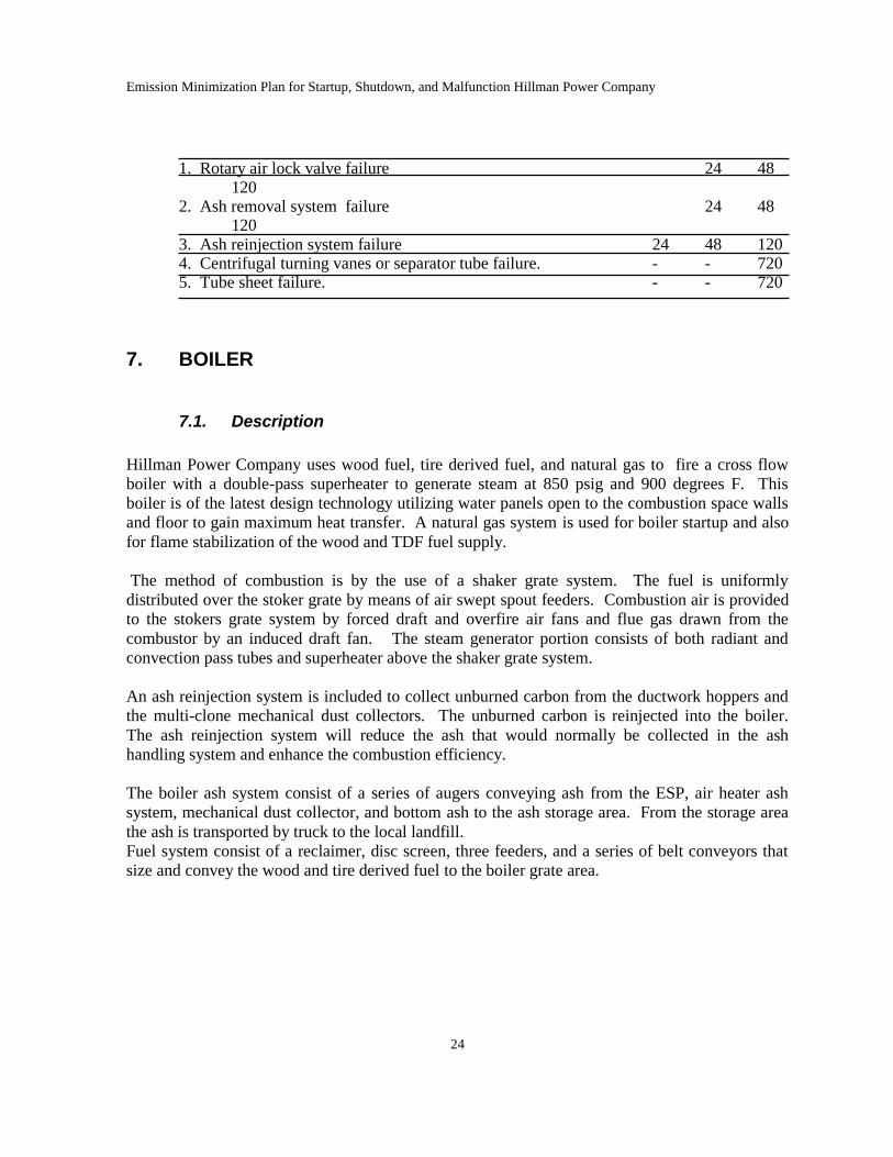
Abnormal conditions or malfunctions 6.8 Abatement measures times in hours
a b c
Emission Minimization Plan for Startup, Shutdown, and Malfunction Hillman Power Company
24
1. Rotary air lock valve failure 24 48 120 2. Ash removal system failure 24 48 120 3. Ash reinjection system failure 24 48 120 4. Centrifugal turning vanes or separator tube failure. - - 720 5. Tube sheet failure. - - 720
7. BOILER
7.1. Description
Hillman Power Company uses wood fuel, tire derived fuel, and natural gas to fire a cross flow
boiler with a double-pass superheater to generate steam at 850 psig and 900 degrees F. This
boiler is of the latest design technology utilizing water panels open to the combustion space walls
and floor to gain maximum heat transfer. A natural gas system is used for boiler startup and also
for flame stabilization of the wood and TDF fuel supply.
The method of combustion is by the use of a shaker grate system. The fuel is uniformly
distributed over the stoker grate by means of air swept spout feeders. Combustion air is provided
to the stokers grate system by forced draft and overfire air fans and flue gas drawn from the
combustor by an induced draft fan. The steam generator portion consists of both radiant and
convection pass tubes and superheater above the shaker grate system.
An ash reinjection system is included to collect unburned carbon from the ductwork hoppers and
the multi-clone mechanical dust collectors. The unburned carbon is reinjected into the boiler.
The ash reinjection system will reduce the ash that would normally be collected in the ash
handling system and enhance the combustion efficiency.
The boiler ash system consist of a series of augers conveying ash from the ESP, air heater ash
system, mechanical dust collector, and bottom ash to the ash storage area. From the storage area
the ash is transported by truck to the local landfill.
Fuel system consist of a reclaimer, disc screen, three feeders, and a series of belt conveyors that
size and convey the wood and tire derived fuel to the boiler grate area.
7.2. Operation
The boiler is operated by properly trained boiler operators who will operate the equipment in
accordance with the manufacturer’s recommendations and plant operating procedures.
Combustion control of the boiler, monitoring of boiler parameters and alarms for the boiler are
directed by the main plant Distributed Control System (DCS) located in the main control room.
Specific functions of the boiler controls are as follows:
a. Control steam flow, pressure, and temperature from the superheater to the steam
turbine generator.
b. Control fuel feed rate to the boiler for proper heat input to satisfy the required steam
generation rate.
c. Control fuel air ratio through the forced draft, overfire air, and induced draft fans.
d. Control grate shaker sequence for proper and complete combustion for the fuel.
e. Control steam drum water level and pressure to ensure proper boiler circulation and
steam flow.
f. Monitor and record boiler operating parameters and auxiliary equipment.
g. Monitor all motion detection devices.
Above items are monitored 24 hours a day by the plant operator and DCS system.
7.3. Critical Criteria
Proper control and efficient operation of the boiler also ensures that complete combustion is
achieved and emissions minimized. In order for the overall plant emissions to be in compliance
with the current Air Use Permit, the boiler is operated to maintain the following critical criteria:
Particulate
a. Wood and tire derived fuel consisting of chips sized at minus 2.5” x 2.5”, saw dust and
planer mill fines are burned in the boiler. The specification for the wood fuel and tire
derived fuel is as described in the Fuel Analysis added as attachment #12.
b. Efficient operation of the boiler will also ensure that complete combustion is taking
place and that the amount of particulate consisting of fly ash is minimized. The
predicted efficiency of the boiler is 68 %. The efficiency of the boiler is directly
related to maintaining the fuel to air ratio, which will provide an excess air leaving the
furnace a approximately 5 % O2 while burning approximately 28 ton per hour of fuel.
NOx
a. Efficient operation of the boiler also influences the generation of NOx . The
boiler is designed to maintain proper combustion temperatures to minimize the
generation of NOx through control of the fuel air ratio. The predicted NOx
levels before reduction by the SNCR system is approximately 0.30 #/mbtu
heat
Emission Minimization Plan for Startup, Shutdown, and Malfunction Hillman Power Company
26
input. Again this is demonstrated by maintaining the excess air leaving the
furnace at 5% oxygen. The excess air is being monitored and recorded by the
CEM equipment as required by the Air Use Permit.
b. Efficient operation of the boiler also controls the flue gas temperature in the
furnace in the region where the urea chemical is to be injected from the SNCR
system. In this area of the furnace the flue gas temperature will range from
1700 to 2000 degrees.
CO
a. Efficient operation of the boiler also influences the generation or CO. In as
much as the generation of CO is somewhat related to the level of NOx , as long as
the NOx is being maintained at 0.30 #/mbtu heat input before reduction, CO
should also be controlled. One distinct exception is the moisture content in the
fuel.
Opacity
a. Wood fuel and tire derived fuel consisting of chips sized at minus 2.5” x 2.5”,
sawdust and planer mill fines are burned in the boiler. The specification for the
fuels in the Fuel Analysis is included in the attachments.
b. Efficient operation of the boiler will also ensure that complete combustion is
taking place and that the opacity will be minimized.
VOC
a. Efficient operation of the boiler influences the generation of VOC emissions.
7.4. Inspections
Inspections are performed every four hours on the boiler to ensure that the equipment is operating
properly and to observe various changes that may indicate potential malfunction. The complete
plant is monitored continuously by the plant DCS System which alarms the Operator Tech as to
any function that varies from the average operation by a few percentage points. The inspections
to be performed each round are as follows: see logs in section 13
a. Observe the stoker distribution and grate area. Log #4
b. Observe the grate shakers are working properly. Log #4
c. Record bearing temperature and condition of forced draft fan. Log #4
d. Record bearing temperature and condition of overfire air fan. Log #4
e. Record bearing temperature and condition of induced draft fan. Log #4
f. Observe the complete ash system. Log #4
Emission Minimization Plan for Startup, Shutdown, and Malfunction Hillman Power Company
27
g. Observe the complete fuel system. Log #6
Through the process of normal operation other operating parameter are continuously observed in
the control room including boiler pressures, temperature, functions of controls, and performance
of the systems. A copy of the daily inspection round logs are added as attachment #13.
Annual inspections will be performed on the boiler to ensure that the equipment is in proper
operating condition. The annual inspection also will include a boiler inspection by the insurance
carrier. Annual inspections will include the following equipment: see work orders log #5 section
13. See also boiler license in control room.
a. All pumps pertaining to boilerwater, feedwater, and condensate.
b. All boiler air fans.
c. Internal inspection of the stoker grate, boiler water walls, superheater, economizer,
air heater, refractory, sidewalls and seals.
d. Fuel system
e. Ash system
7.5. Maintenance
Maintenance on the boiler is performed in accordance with the manufacturer’s recommendations
and plant operating experience. Normal maintenance is performed during the annual inspection
with the replacement of worn parts that do not meet the manufacturer’s specification tolerances.
Other maintenance will be performed to either replace or rebuild various pieces of equipment
should a malfunction occur and force the shut down of the boiler.
7.6. Spare Parts
Spare parts are purchased and stored in inventory based on plant operating experience. The
expected spare parts list is added as attachment # 13.
7.7. Abnormal conditions, malfunctions, and startup and shutdown
a. Loss of fuel feeders
b. Rotary air damper failure
c. Hydrograte failure
d. Bottom ash conveyor failure
e. Boiler air fan system and controls
f. High moisture content in incoming fuel
g. High flue gas temp
h. Loss of incoming fuel
i. Ash system failure
j. Loss of boiler refractory
k. Plant air supply system failure
Emission Minimization Plan for Startup, Shutdown, and Malfunction Hillman Power Company
28
l. Nitrogen content in alternative fuels
m. Clinkers and slagging on the Hydrograte system
n. Incoming line voltage surges
o. Safety valve failure
p. Scheduled maintenance
q. Distributed Control system failure (DCS)
r. Turbine/generator system failure
s. Transfer trip failure (Consumers Power emergency trip system)
t. Condenser tube failure
u. Loss of feedwater control
v. Electrical equipment and or control failure
w. Substation equipment and or control failure
x. Cooling water system failure
y. Boiler tube failure
z. Act of God (For example Electrical storm hit by lightning)
7.8. Abatement measures
In the event that a malfunction should occur to the boiler or related equipment that affects the
control of the plants emissions and causes the plant to exceed the permitted levels, specific action
will b taken to bring the plant back into compliance.
Whenever needed the use of overtime, off-shift labor, outside consultants or contractors, where
reasonable to minimize the duration of the malfunction or excess emissions will be used. This
action in cooperation with the DEQ-AQD district supervisor will be taken and either one or more
of the following steps:
a. Continue to run the malfunctioned equipment at lower loads as long as the plant
emissions are in compliance.. This may or may not require the boiler to run at reduced
loads.
b. Correct the malfunctioned equipment by taking it out of service for repairs. It may
be necessary to run the boiler at reduced loads to be in compliance with emissions
when the malfunctioned equipment is out of service for repairs.
c. Continue to run the boiler and repair the equipment, if the repair takes less time than
the time required for a normal boiler shutdown and startup. Emissions may exceed
the permit limits for certain periods of time during boiler startup and shutdown. This
situation may be unavoidable and is addressed in the emission minimization plan
during startup and shutdown (see Section 7).
d. Correct the malfunctioned equipment by shutting down the boiler and repair the
equipment. Shutting down the boiler will cease all plant emissions.
Emission Minimization Plan for Startup, Shutdown, and Malfunction Hillman Power Company
29
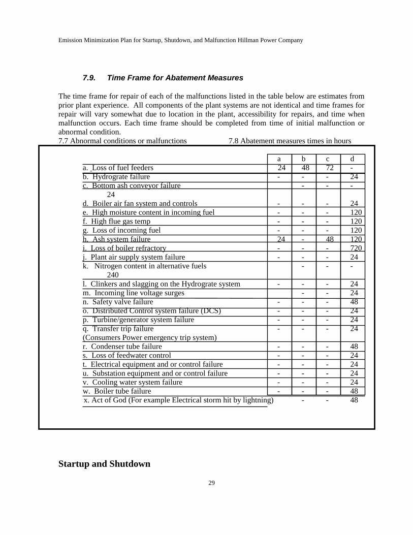
7.9. Time Frame for Abatement Measures
The time frame for repair of each of the malfunctions listed in the table below are estimates from
prior plant experience. All components of the plant systems are not identical and time frames for
repair will vary somewhat due to location in the plant, accessibility for repairs, and time when
malfunction occurs. Each time frame should be completed from time of initial malfunction or
abnormal condition.
7.7 Abnormal conditions or malfunctions 7.8 Abatement measures times in hours
a b c d
a. Loss of fuel feeders 24 48 72 -
b. Hydrograte failure - - - 24
c. Bottom ash conveyor failure - - -
24
d. Boiler air fan system and controls - - - 24
e. High moisture content in incoming fuel - - - 120
f. High flue gas temp - - - 120
g. Loss of incoming fuel - - - 120
h. Ash system failure 24 - 48 120
i. Loss of boiler refractory - - - 720
j. Plant air supply system failure - - - 24
k. Nitrogen content in alternative fuels - - -
240
l. Clinkers and slagging on the Hydrograte system - - - 24
m. Incoming line voltage surges - - 24
n. Safety valve failure - - - 48
o. Distributed Control system failure (DCS) - - - 24
p. Turbine/generator system failure - - - 24
q. Transfer trip failure - - - 24
(Consumers Power emergency trip system)
r. Condenser tube failure - - - 48
s. Loss of feedwater control - - - 24
t. Electrical equipment and or control failure - - - 24
u. Substation equipment and or control failure - - - 24
v. Cooling water system failure - - - 24
w. Boiler tube failure - - - 48
x. Act of God (For example Electrical storm hit by lightning) - - 48
Startup and Shutdown
Emission Minimization Plan for Startup, Shutdown, and Malfunction Hillman Power Company
30
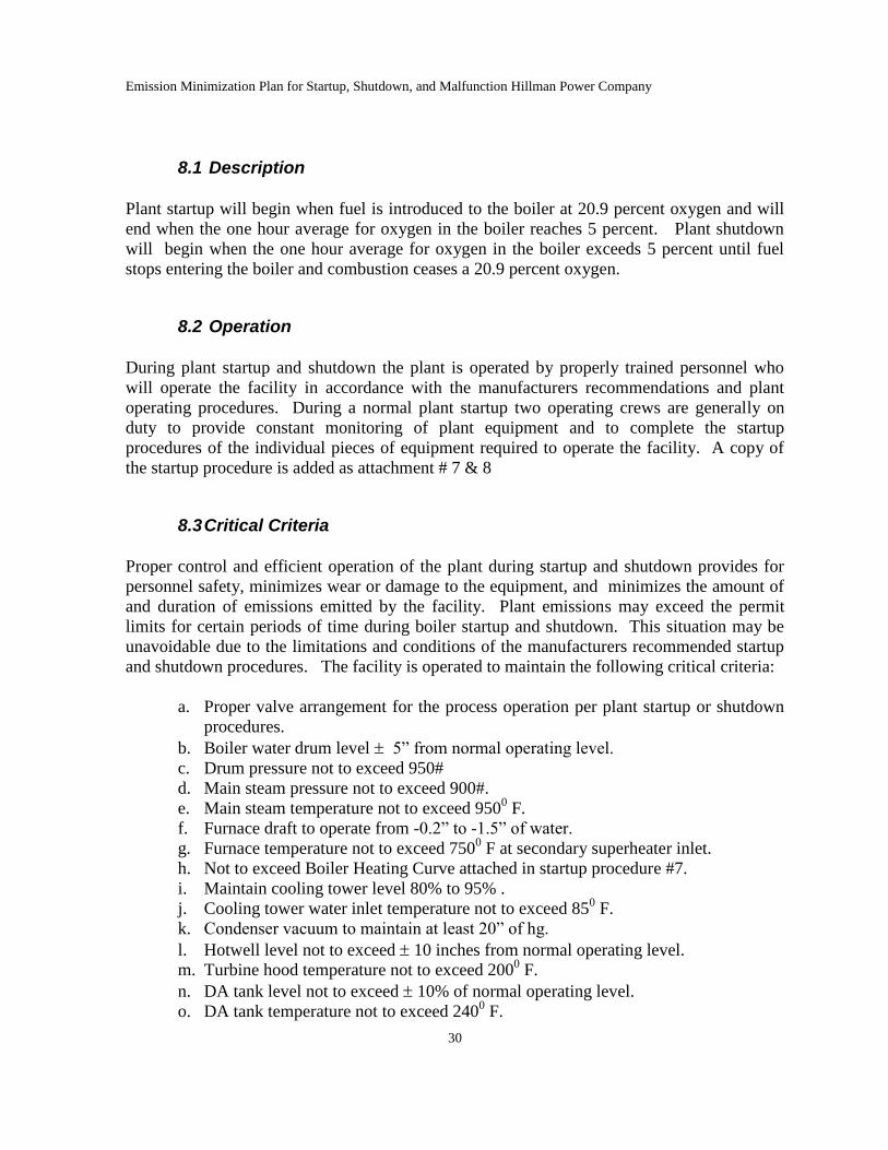
8.1 Description
Plant startup will begin when fuel is introduced to the boiler at 20.9 percent oxygen and will
end when the one hour average for oxygen in the boiler reaches 5 percent. Plant shutdown
will begin when the one hour average for oxygen in the boiler exceeds 5 percent until fuel
stops entering the boiler and combustion ceases a 20.9 percent oxygen.
8.2 Operation
During plant startup and shutdown the plant is operated by properly trained personnel who
will operate the facility in accordance with the manufacturers recommendations and plant
operating procedures. During a normal plant startup two operating crews are generally on
duty to provide constant monitoring of plant equipment and to complete the startup
procedures of the individual pieces of equipment required to operate the facility. A copy of
the startup procedure is added as attachment # 7 & 8
8.3 Critical Criteria
Proper control and efficient operation of the plant during startup and shutdown provides for
personnel safety, minimizes wear or damage to the equipment, and minimizes the amount of
and duration of emissions emitted by the facility. Plant emissions may exceed the permit
limits for certain periods of time during boiler startup and shutdown. This situation may be
unavoidable due to the limitations and conditions of the manufacturers recommended startup
and shutdown procedures. The facility is operated to maintain the following critical criteria:
a. Proper valve arrangement for the process operation per plant startup or shutdown
procedures.
b. Boiler water drum level 5” from normal operating level.
c. Drum pressure not to exceed 950#
d. Main steam pressure not to exceed 900#.
e. Main steam temperature not to exceed 9500 F.
f. Furnace draft to operate from -0.2” to -1.5” of water.
g. Furnace temperature not to exceed 7500 F at secondary superheater inlet.
h. Not to exceed Boiler Heating Curve attached in startup procedure #7.
i. Maintain cooling tower level 80% to 95% .
j. Cooling tower water inlet temperature not to exceed 850 F.
k. Condenser vacuum to maintain at least 20” of hg.
l. Hotwell level not to exceed 10 inches from normal operating level.
m. Turbine hood temperature not to exceed 2000 F.
n. DA tank level not to exceed 10% of normal operating level.
o. DA tank temperature not to exceed 2400 F.
Emission Minimization Plan for Startup, Shutdown, and Malfunction Hillman Power Company
31
p. Reduce oxygen level in the boiler to below 8% as soon as operating condition
allow.
q. Maintain feed water pump pressure less than 1300#.
r. Lube oil temperature not to be less than 900 F, or greater than 140
0 F.
s. Maintain boiler water chemistry as per manufacturers recommendations.
t. Maintain hydrogen purity in the generator above 90%.
u. Transformer Rectifier spark rate not to exceed 240 sparks per minute.
v. Account for all personnel on sight at all times.
8.4 Inspections
Inspections are performed on a continuous basic during startup to ensure that the equipment is
operating properly and to observe various changes that may indicate potential malfunction.
The inspections include all previous inspection items listed in this program as well as many
others that pertain to the complete operation of the facility.
8.5 Maintenance
Maintenance is performed to either replace or rebuild various pieces of equipment should a
malfunction occur. Maintenance during startup and shutdown is performed as needed to
ensure a successful operation, and to minimize the amount and duration of excess emissions.
8.6 Abatement Measures
In the event that a malfunction or an abnormal condition should occur during startup or shutdown
the abatement measures listed in the previous sections of this program will be complied with.
9. MATERIAL HANDLING
9.1 Description
FGMATLHANDLING consists of fuel and ash handling for the plant. The major fuel handling
operations includes fuel unloading from trucks, storage piles and storage pile management (i.e.,
loader and dozer moving fuel around), reclaimer, screen, and conveyors. The ash handling
includes removing bottom ash, sand ash and flyash from the boiler and air pollution control
systems, storage, and loading ash into trucks for removal from the site.
9.2 Operation
The material handling systems are continuous operating systems while the boiler is operating.
Fuel is continuously fed to the boiler in an amount greater than needed to operate the plant to
Emission Minimization Plan for Startup, Shutdown, and Malfunction Hillman Power Company
32
ensure continuous flow of fuel to the boiler. The excess material leaves the plant and is piled in
an overfeed area. This material is then reintroduced into the fuel feed system through the reclaim
area.
Bottom ash is removed from the bottom of the boiler in a water bath and stored in an ash bay
located inside the ash building. Sand ash exits from the air heater system and is stored in a
different ash bay in the ash building. The sand ash from the multiclones as well as the flyash from
the ESP is removed and augered in an enclosed system. The ash from the multiclones and
precipitator are mixed together with water in the enclosed system before dropping into a pile in a
separate bay in the ash building. All ash is loaded onto truck to be removed from the site.
9.3 Critical Criteria
The operation of the material handling system is critical in controlling the particulate emissions
from the boiler, as well as dust emissions from the material handling sources. Disruptions in fuel
supply or ash removal can put the plant into an upset condition causing the plant to be less
efficient causing the precipitator to work harder.
9.4 Inspections
Daily inspections are performed on the material handling system to ensure that the equipment is
operating properly and to observe various changes that may indicate potential malfunction. The
inspections to be performed each day are as follows:
a. Fuel operators observe the operation of the fuel system.
b. Plant operators observe the operation of the ash removal system.
Additional inspections are performed on the material handling system weekly by maintenance
personal to ensure that the equipment is in proper operating condition.
Due to the abrasive nature of the fuel and ash materials, packing material in the auger system and
skirting material around the conveyors can erode away and need to be replaced periodically.
9.5 Maintenance
Maintenance on the material handling system is performed in accordance with the manufacture’s
recommendations and plant operating experience. Normal maintenance is performed during the
annual inspection with the replacement of worn parts that do not meet the manufacturer’s
specification tolerances. Other maintenance will be performed to either replace or rebuild
various pieces of equipment should a malfunction occur and force the shutdown of the boiler
9.6 Spare parts
Emission Minimization Plan for Startup, Shutdown, and Malfunction Hillman Power Company
33
Spare parts are purchased and stored in inventory (packing for ash auger system and skirting for
fuel handling systems).
9.7 Abnormal conditions and malfunctions
The following is a list of specific equipment that is observed and inspected for emissions or
operations outside the permit requirements (i.e., visible emissions):
a. Reclaimer
b. Reclaimer to screen conveyor
c. Screen
d. Screen to boiler conveyor.
e. Feeder distribution conveyor
f. Overfeed conveyor
g. Ash auger 396
h. Rotary air lock 517
I. Ash auger 505
J. Ash auger 506
9.8 Abatement measures
Malfunctions that occur to material handling systems that affect the control of the boiler emissions
are addressed in Section 7.
Malfunctions that occur to material handling systems that result in visible emissions noted in a
daily inspection results in the generation of a work order in the maintenance management system
for repair of skirting for the fuel handling system or packing in the ash handling auger system.
This work order is marked environmental. Any work order marked safety or environmental get
top priority and the cited situation is corrected within 24 hours.
9.9 Time Frame for Abatement Measures
The timeframe for repair of each of the malfunctions listed in table 7.9 are estimates from prior
plant experience. All components of the plant systems are not identical and time frames for repair
will vary somewhat due to location in the plant, accessibility for repairs, and time when
malfunction occurs. Each time frame should be completed from time of initial malfunction or
abnormal condition.