representing etl flows with bpmn 2 - it4bi.ulb.ac.be · bpmn 2.0 includes a meta-model that...
TRANSCRIPT

Representing ETL Flows with BPMN 2.0
Author: Elena SamotaAdvisors: Petar Jovanovic, Alberto Abello, and Oscar Romero
Universitat Politecnica de Catalunya({esamota|petar|aabello|oromero}@essi.upc.edu)
Abstract. Extract, Transform and Load (ETL) processes are widely used inData Warehousing in order to extract, cleanse and load data into a central-ized location for better analysis and decision-making. As users become moredemanding for on-line decision making, ETL processes grow large and morecomplex. Most processes are deployed at the physical level without any ab-straction, thus costs of maintenance and efforts for reuse are considerable.Therefore, having logical and conceptual abstractions of ETL processes makessuch tasks substantially easier.In this thesis, given a logical ETL representation, we provide an algorithmthat automatically translates logical ETL flows into their BPMN represen-tation. To achieve this goal, we create a dictionary that defines simple andcomposite ETL flow patterns and their corresponding BPMN elements. Thepattern dictionary follows a formalized grammar and can be further extendedwith additional ETL flow patterns.As a result, we can produce conceptual ETL flows in BPMN 2.0 format thatcan be further edited by the business user. The patterns defined in the dic-tionary help to move away from technical details and complexity of the ETLflows and make the output model semantics more intuitive and understandablefor the business users, as shown during the approach validation.
Keywords: Data Warehouses, ETL, BPMN, Patterns, Reverse Engineering,Process Mining, xLM, Conceptual Modeling
1 Introduction
ETL process represents a data flow in a Data Warehousing system that extracts,transforms, cleans, and loads data in formats ready for further analysis and explo-ration. This process is widely used in Business Intelligence projects, and is consideredas one of the most complex, error-prone, and time consuming tasks. The complexityoften comes from the lack of standardization of capabilities offered by different toolsin this field. Such tools have different underlying languages with various sets of fea-tures and wizards which would make conceptually similar models look quite differentat the physical level [2].Some recent approaches (i.e., [2], [12], [21]) that propose methodologies to includeconceptual modeling into the ETL design process assume that the model will be cre-ated as part of the design process. However, most organizations already have a largenumber of ETL processes designed and deployed without any logical or conceptualabstraction. Hence, being able to understand, maintain and reuse existing processesrequires a cumbersome task of discovering the underlying logic of the process and

2 Authors Suppressed Due to Excessive Length
Fig. 1. Merge Join: from Physical to Conceptual
what each component is responsible for. There is an obvious need for raising the levelof abstraction of existing models to the conceptual level, where business users canhave an overview of the main logic of the flow, as well as the different ETL flow pat-terns.In the traditional database design, the three levels of data modeling (i.e., conceptual,logical, and physical) have been proven as an effective method to ensure the qual-ity, understandability, and reusability of the models despite the database provider.Motivated by this idea, we think it is important to separate ETL design into thesethree levels of abstraction as well. The notable difference, however, lays in the orderof model creation during the modeling phase. In database design, the process startswith conceptual, going to logical, and ending in physical level, whereas our goal isto go backwards (physical - logical - conceptual) following the principles of reverseengineering.An approach by Wilkinson et al. [21] introduces the first step of the reverse engineer-ing chain, by providing an XML-based logical representation of ETL (i.e., xLM). Ourgoal is to provide the complete reverse engineering process, ending with the conceptualrepresentation of ETL processes expressed in Business Process Model and Notation(BPMN) 2.0.Figure 1 shows a part of an ETL flow at the physical level and the two correspond-
ing mappings in BPMN. The first model is mapped directly, where each componentof the ETL flow is translated to BPMN notation. The second model shows a moreconcise translation, where the mergeJoin is represented in the form of a subprocess.Both BPMN models are syntactically correct, however, one might be preferred overanother based on the business user’s needs. In this particular case, for the high levelview of the process it is often enough to see that the two data inputs are joined,without the implementation details (i.e., the necessity to sort inputs before they aremerged).Even though it is clear that the understandability of the process is much higher whenpresented as a conceptual or logical model, the difficulty of raising the abstractionlevel is not always evident. A conceptual formalization is richer and thus, mappingcomponents one-to-one is not always possible or beneficial to increase the under-standability of the ETL flow, as demonstrated in Figure 1. There is a need to extractsemantics from the physical implementation in order to express concepts that are notnecessarily explicit, but are important for the conceptualization of the process.In order to achieve the goal of conceptualizing ETL processes and making them moreunderstandable and reusable, we start from the logical representation of an ETL pre-sented in [21], and produce a BPMN 2.0 XML as an output conceptual model of thegiven ETL process. The output file can be then visualized and edited using any graph-

Representing ETL Flows with BPMN 2.0 3
ical BPMN editor that supports BPMN 2.0 specification1. Beside simply translatingETL activities into BPMN elements, we also define and discover ETL flow patternsthat can be more familiar to business users and help them in understanding the se-mantics of the given ETL process.
Contributions.
– To enable translation between logical ETL and BPMN, we identified the mappingsbetween their elements.
– To facilitate an automatic translation mechanism, we defined a dictionary thatfollows a formal grammar and can be further extended with new ETL flow patternsand BPMN mappings.
– In terms of the provided dictionary, we defined an extensible list of ETL flowpatterns to enhance the understandability of the ETL flow semantics at the con-ceptual level.
– We introduced a novel algorithm that automatically translates logical ETL processdesigns into conceptual BPMN models.
The paper is organized as follows. In Section 2, we provide a review of related workin ETL design, reverse engineering and process mining fields. Section 3 presents theconceptual idea of our approach and describes the logical representation of ETL thatwe use (i.e., xLM). Formal definitions of the ETL flow graph, ETL flow patterns,dictionary grammar and the algorithm are presented in Section 4. Section 5 demon-strates an enhanced example of an ETL flow and its complete translation to BPMN.Section 6 describes our output validation process and its results. We summarize ourachievements and present ideas for future work in Section 7. Finally, the Appendixcontains a full list of ETL flow patterns currently defined in the dictionary (i.e., Sec-tion A) along with details of empirical studies conducted to validate the approach(i.e., Section B).
2 Related Work
Numerous approaches have already studied the importance of adding a conceptuallevel into ETL design in the last few years. Some tried to achieve this goal with theuse of ontology mapping [17], while others exploited UML models [11], and BPMNnotation ([2], [5], [12]). Using a language that already entails some semantics and doesnot require to define a supplementary ontology, such as UML or BPMN, is preferable.
2.1 ETL in BPMN
BPMN is the most cited and used in practice OMG’s Business Process Model stan-dard that covers a large amount of the real world concepts and is already incorpo-rated into many organizations as a de-facto process modeling language [16]. Moreover,BPMN 2.0 includes a meta-model that represents the language’s constructs and theirrelationships in XML format. BPMN 2.0 XML serialization allows for model inter-changeability within BPM tools from different vendors [13].Akkakoui and Zimany argue the benefits of using BPMN notation to conceptualize
1 http://www.omg.org/spec/BPMN/2.0/

4 Authors Suppressed Due to Excessive Length
ETL processes and automate the translation of BPMN into an executable represen-tation, such as BPEL (i.e., a standard executable language for specifying interactionswith web services) in [5]. Later, in 2013, they present a meta-model framework thatsupports the development of ETL systems using BPMN and generates code specificto several ETL commercial tools [2]. Oliveira and Belo use BPMN to provide a setof meta-models, also referred to as patterns, that enhance testing and validation ofstandard ETL processes before the construction of the final data warehousing system.The ideas presented by these authors are value-adding for ETL design and mainte-nance, however, they are meant to guide the design or enhancement of existing BPMNmodels for ETL processes. Our approach, on the other hand, produces a BPMN modelas a result of ETL flow translation from its logical to conceptual form. We aim atenhancing the understandability and reusability of already deployed ETL processesand not the design of new systems.Wilkinson et al. propose BPMN as an ETL conceptual model in [21] and show howto translate it to a logical ETL representation, xLM (i.e., the reverse of what we aretrying to achieve). This approach claims that the translation of BPMN (in XPDL2
serialization format) to xLM is straightforward. However, the reverse mapping ap-pears to be more complex. In order to extract proper semantics from xLM, reverseengineering and process mining knowledge is used in our approach.
2.2 Reverse Engineering
The traditional area of reverse engineering that is most applicable to our needs issoftware reverse engineering (SRE), where design patterns and cliche discovery areoften used to extract software design or architecture from the source code. In SRE,when dealing with legacy systems, it is often helpful to abstract and recover the de-sign from the source code, existing documents, developers’ knowledge and applicationdomain knowledge [3].Linda Wills was one of the first who claimed that cliche matching is an effectivemethod for architecture recovery [22]. Wills developed the GRASPR environmentthat used flow graph parsing and a cliche grammar to identify cliches and the rela-tionships between them. Sartipi proposed an Architecture Query Language (AQL) toenable users to create architectural patterns and later match them against the sourcecode represented as an attributed relational graph [14]. Others applied a similarityscoring approach to depict design patterns in a class diagram [19]. A semantic clus-tering approach based on Latent Semantic Indexing (LSI) was also proposed by [8] inorder to compute linguistic similarity between source artifacts.While these approaches prove their effectiveness in the field of SRE, they all requirethe source code as an input and produce design trees or distribution maps that depictidentified patterns. Our approach uses a different input, xLM, that is more suitableto represent the nature of data flows (e.g., flow resources, properties, data elements,etc.) and to produce an output model in any format that can depict control flow, suchas a sequence diagram. In this work, ETL is not viewed as a software program, butas an encapsulation of code, hence the problem is noticeably different from standardSRE.
2 XPDL is a standard offered by the Workflow Management Coalition (WfMC) as a formatto interchange business process definitions between different workflow products. XPDLused to be a de-facto standard for model interchange until January 2011 when BPMN 2.0introduced its own serialization standard.

Representing ETL Flows with BPMN 2.0 5
2.3 Process Mining
Another area that leverages reverse engineering in order to discover business pro-cesses is process mining. More precisely, process mining is used to discover, improveand monitor processes based on the knowledge extracted from event logs and pro-duces a process model as result of the discovery [1].The majority of existing process mining techniques are based on Business ProcessManagement (BPM) languages that have proper formal semantics and can be verifiedin a formal way, such as Petri nets. The industry, however, is using notations thatare more suitable for representing real world situations, but lack proper semanticsand can be often interpreted in different ways [10]. Authors claim, since BPMN isbecoming a de-facto standard for BPM, it is essential to be able to produce BPMNmodels as a result of process mining techniques.As Kalenkova et al. suggest in [7], instead of replacing or improving existing tech-niques, it might be easier to simply translate a given formal definition such as Petrinet into an industry-popular language, BPMN.A bulk of existing techniques produce flat models when translating from Petri netsto BPMN, discovering only activities, connecting arcs and gateways, similar to thedirect translation in Figure 1. However, obtaining a more abstract or semanticallyrich BPMN representation (i.e., the subprocess in Figure 1) is less straightforward.A two-phase discovery method to recover subprocesses is proposed in [9] where pat-tern detection techniques are applied on the event log in order to uncover loops (i.e.,tandem arrays) and maximal common subsequences of activities in a process instance(i.e., maximal repeats). The idea is that these footprints correspond to the presenceof a subprocess in the event log.Based on the two-phase method, Conforti et al. are able to recognize subprocesses,interrupting boundary events, and multi-instance activities by analyzing dependen-cies between event attributes [4]. This technique is applied to split the log into parentand subprocess logs and uses existing discovery techniques for each log to produceflat models. Another state-of-the-art approach is presented by [7] who developed theplug-ins for ProM3 that claim to depict different types of data objects, swimlanes,subprocesses and events.Process mining techniques that transform Petri nets into BPMN also require the use
of patterns in order to identify BPMN constructs within a Petri net because BPMN is
3 ProM is a widely used open-source extensible framework that supports a variety of processmining techniques in the form of plug-ins.
Table 1. Comparison with State of the Art in Process Mining
BPMN Element Kalenkova Conforti Samota
Activity X X X
Connecting Arc X X X
Gateway X X X
Data Objects X - X
Swimlane X - -
Subprocess - X X
Events -Timer interrupting
Interrupting-
Markers -Loop
Multi-instanceCompensationMulti-instance

6 Authors Suppressed Due to Excessive Length
more expressive and abstract, similar to the transformation between the logical ETLflow and BPMN.In Table 1, we provide a comparison between the achievements of [7] and [4] whenproducing BPMN models from Petri nets with our approach of translating logicalETL flows to BPMN.While most process mining techniques benefit from execution traces, our approach isbased on a different input, a data flow graph, hence identifying control-flow and exe-cution related behavior is not always easy or even possible. However, the logical ETLrepresentation contains the information such as operation type, implementation type,input and output schemata, node parameters, properties and features. This knowl-edge allows us to go beyond what is currently possible in Process Mining.We are able to discover ETL flow patterns and create BPMN structures that are typ-ical for ETL flows and much more intuitive to the business users (i.e., checkpointing,compensations actions, or flow replication).
3 Proposed Solution
In this section, we describe the prototype architecture and provide additional knowl-edge about the logical representation that is used to obtain a conceptual view of anETL flow. Figure 2 depicts the architecture of the proposed solution.The physical level is represented by an ETL flow that can be edited by a technicaluser. The Logical Model Extraction module produces a logical representation of theETL flow in an XML-based language (i.e., xML). The conceptual level of Figure 2depicts the contribution of this paper: Flow Pattern Discovery and Conceptual ModelCreation modules, which translate the input ETL flow into the BPMN format. FlowPattern Discovery module first uses the dictionary to check if the defined ETL flowpatterns are present in the ETL flow and then obtains their corresponding BPMNmappings. The Conceptual Model Creation module, in turn, is responsible for fillingin and creating all of the necessary attribute values for the obtained BPMN elementsand constructing a valid BPMN 2.0 XML file.The logical representation model that we use as an input, xLM, is an XML-based
flow metadata language with two important structural components, nodes and edges.Design is the main component that describes the flow as a graph with its nodes asoperations or data stores, and edges as data flows between the nodes [6].
Fig. 2. Proposed Architecture

Representing ETL Flows with BPMN 2.0 7
<node><name>Supplier </name><type>Datastore </type><optype >TableInput </optype ><implementation/><implementationType/><engine >SQL</engine ><flowID >2</flowID ><schemata/><ndproperties/><ndresources/><ndfeatures/>
</node>
<node><name>Sort on s_nationkey </name><type>Operator </type><optype >Sort</optype ><implementation/><implementationType/><engine >SQL</engine ><flowID >2</flowID ><schemata/><ndproperties/><ndresources/><ndfeatures/>
</node>
<edge><from>Supplier </from><to>Sort on s_nationkey </to><enabled >Y</enabled >
</edge>
Code Snippet 1.1. xLM Nodes and Edges
Every node specifies a unique name, carries information about whether it representsa data store or an operation (i.e., type), and describes its functionality through a listof parameters:
– operation type such as Sort, Join, or Filter for operations, and TableInput orTableOutput among others for the data stores.
– implementation type for each operation; for instance, a Join operator can be im-plemented as a merge or a hash.
– engine type, alternatively for each node specifies the engine where the operationof that node is executed, e.g., SQL, Pentaho Data Integration (PDI).
– schemata describes the input and output schema as well as parameters that con-tain the semantics of each operation (i.e., sorting, filtering or join conditions).
We omit other node parameters that are not used in the paper for simplicity.Code Snippet 1.1 shows the xLM representation of an operator, a data store, andan edge between the two given nodes. Code Snippet 1.2 depicts a closer look at theparameters schema of the Sort operation, where the operation semantics are specified(i.e., the input file is sorted in ascending order). Note, that these nodes are part ofthe initial ETL to BPMN example in Figure 1.
<schemata ><parameter >
<param><pengine >SQL</pengine ><ptype>order_attr </ptype><expr>
<leftfun ></leftfun ><leftop ></leftop ><oper></oper><rightfun >$$ $1 ASC</rightfun ><rightop >Input_1.s_nationkey </rightop >
</expr></param >
</parameter ></schemata >
Code Snippet 1.2. Example of Sort Node Parameters

8 Authors Suppressed Due to Excessive Length
Table 2. Direct xLM Operation Mappings to BPMN
ETL Transformation Type [20] xLM Operation Type BPMN Element
Unary Row Level (1:1)AttributeAddition, Rename,Filter, Project, WSLookup,
UserDefinedFunction TaskUnary Grouper (N:1) Grouper, DistinctUnary Holistic (N:M) Sort, TopK
N-aryUnion Parallel Gateway (AND-Join)
Join, LeftOuterJoin, MergerParallel Gateway, Sequence flow,
TaskVoter Event Based Gateway
Routers & FiltersRouter Complex Gateway, Edge ConditionsSplitter Parallel Gateway (AND-Split)
In order to achieve the translation from logical to conceptual models, we first triedto directly map xLM edges and nodes to BPMN elements, similar to the approach in[4]. Edges are translated to BPMN sequence flows, nodes of type Datastore to datastores, and a combination of node’s engine type and flowID defines the correspondingunique pool in BPMN (e.g., both TableInput and Sort in Figure 1.1 are part of thepool SQL 2). With regards to the nodes’ operation types, we discovered that not allof the mappings are syntactic and some require multiple BPMN elements to representa single xLM node (e.g., Join).Table 2 illustrates the single operation (i.e., simple) patterns that were considered inthis paper and their mappings to BPMN. We put these mappings in the context ofa well-known taxonomy of ETL transformations presented in [20] to try to classifyETL activities being mapped to BPMN. However, we noticed that for some classesof ETL activities defined in the taxonomy, we have several operations mapping todifferent BPMN elements. This showed us that for determining the translation ofETL activities into BPMN elements, we typically need additional information aboutspecific ETL operation semantics.For example, both Splitter and Router are classified under Routers & Filters in thetaxonomy, since from a single input schema they generate multiple outputs. However,Splitter maps to a simple AND-Split, while Router maps to a complex gateway, wherethe input flow is routed to different outputs based on a given condition.Using only the simple ETL flow pattern mappings from Table 2, we can obtain aBPMN model as a literal translation of an input ETL process, still burdened withinput flow complexity and technical terminology (e.g., see middle part of Figure 1).Similarly to the way natural languages are translated, we can use literal translations,but these are often not in the spirit of the destination language or notation and some-times cannot be understood or appreciated as such. Thus, when translating from onelanguage to another, additional techniques are used to give the translation a flavor ofthe destination language.In ETL flow translation, we use the pattern matching techniques as suggested by theresearch in SRE to enrich the BPMN model with the semantics available in the log-ical representation. The literal translations usually only use BPMN tasks, gatewaysand sequence flows. However, we also want to detect parts of ETL flows that can benicely represented with other BPMN elements (i.e., events, subprocesses, markers) toimprove the understandability of a model by business users.We use the pattern dictionary that enables us to define and translate ETL flow pat-terns. We generalize the pattern dictionary to capture both, the simple patterns (i.e.,direct mappings of ETL operations) such as a Router, and the composite patternsthat typically contain subflows of ETL operations (e.g., recoveryPoint pattern could

Representing ETL Flows with BPMN 2.0 9
contain a Router and a FileOutput). The dictionary follows a formal grammar thatis defined in Section 4.2 and can be extended to support new patterns and mappings.Composite ETL flow patterns are designed to group together ETL flow operationsbased on their semantics and relation within the flow. Currently, our approach con-siders the following composite ETL flow patterns:
– mergeJoin - a user defined pattern that depicts a merge-Join between two sorteddata inputs in an ETL flow;
– recoveryPoint - a user defined pattern that identifies check-pointing in an ETLflow;
– compensation - a user defined pattern that depicts compensation action operationsin an ETL flow;
– replication - a user defined pattern that identifies replicated flows in an ETL flow;– externalDataValidationWS - a user defined pattern that identifies data quality
actions in an ETL flow data input (e.g., cross-checking names or titles, filling inmissing information, etc.) via a web service call.
4 Formalization
In this section, we first define the ETL flow graph and the ETL flow pattern. Then,we formalize the pattern dictionary and introduce its parsing details. Finally, wepresent an algorithm that discovers ETL flow patterns in the graph and translatesa logical ETL into its conceptual representation, while being aware of possible ETLflow pattern nesting.
4.1 ETL Flow Graph and Pattern
The ETL flow graph is an acyclic parameterized digraph G(Ug) = (Vg(Ug), Eg),where:
– Vg is a finite set of vertices;– Ug is a finite set of properties of the vertices Vg;– Eg ⊆ Vg × Vg, having (u, u’) denote an edge from node u to u’.
The ETL flow pattern graph is a user defined acyclic parameterized digraph Pn(Un) =(Vn(Un), En), where Vn, Un and En are the set of vertices, the set of vertex properties,and the set of directed edges, respectively, as defined for the ETL flow graph.
4.2 Dictionary Grammar
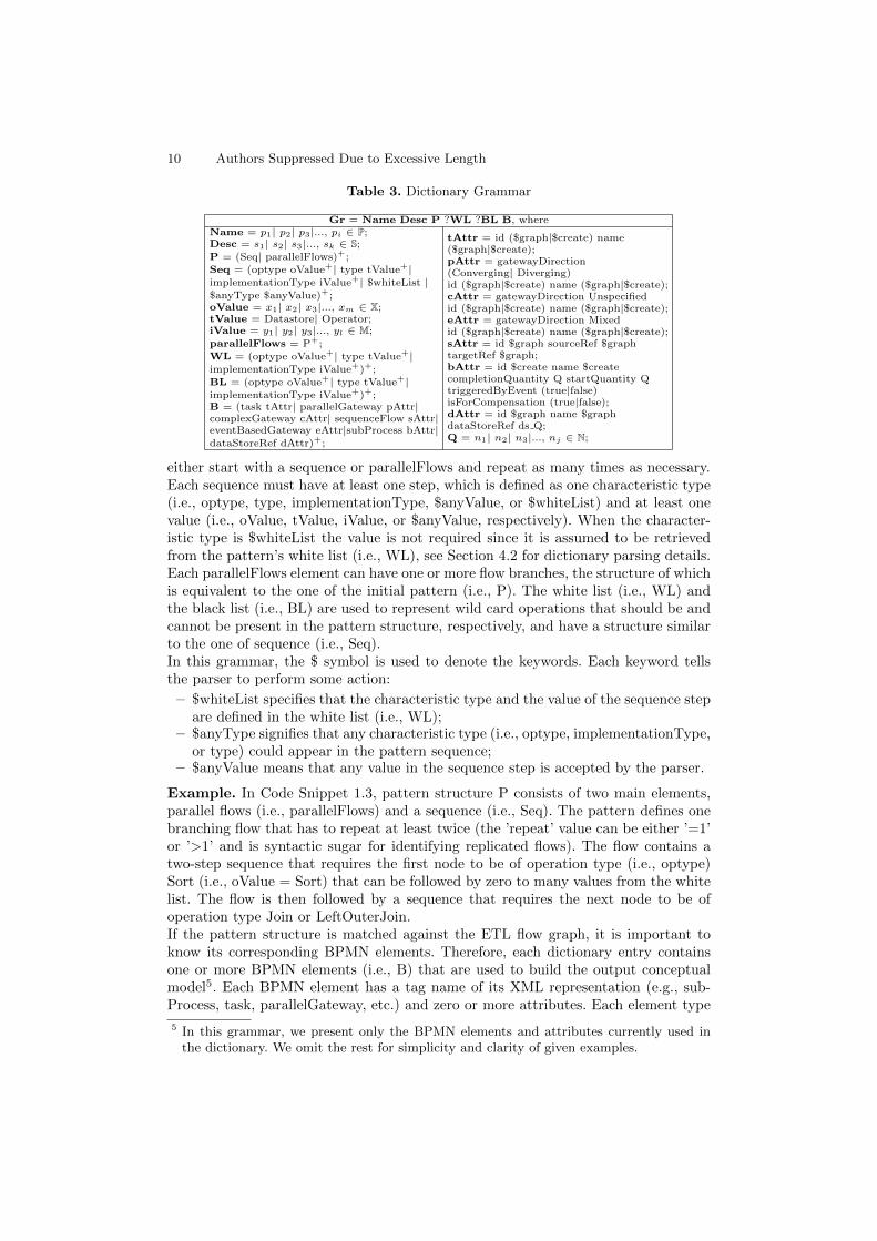
In Table 3, we define a grammar Gr to formalize the expressiveness of the dictionaryand allow others to extend it with new dictionary entries.Each dictionary entry contains a unique name (i.e., Name), a description (i.e., Desc),a pattern structure (i.e., P), an optional white (i.e., WL) and black (i.e., BL) list ofwild card operations that should be and cannot be contained in the pattern, respec-tively and the corresponding BPMN elements (i.e., B).The pattern structure (i.e., P) is defined by two elements, a linear sequence of steps
(i.e., Seq) and a set of flows running in parallel (i.e., parallelFlows)4. The pattern can
4 If a sequence appears before parallelFlows, it is a pattern that branches after a Splitteror a Router (i.e., recoveryPoint, compensation, etc.). On the other hand, if parallelFlowsis the first element of the pattern, the flows start individually and independently of eachother (i.e., mergeJoin).
10 Authors Suppressed Due to Excessive Length
Table 3. Dictionary Grammar
Gr = Name Desc P ?WL ?BL B, whereName = p1| p2| p3|..., pi ∈ P;Desc = s1| s2| s3|..., sk ∈ S;
P = (Seq| parallelFlows)+;
Seq = (optype oValue+| type tValue+|implementationType iValue+| $whiteList |$anyType $anyValue)+;oValue = x1| x2| x3|..., xm ∈ X;tValue = Datastore| Operator;iValue = y1| y2| y3|..., yl ∈ M;
parallelFlows = P+;
WL = (optype oValue+| type tValue+|implementationType iValue+)+;
BL = (optype oValue+| type tValue+|implementationType iValue+)+;B = (task tAttr| parallelGateway pAttr|complexGateway cAttr| sequenceFlow sAttr|eventBasedGateway eAttr|subProcess bAttr|dataStoreRef dAttr)+;
tAttr = id ($graph|$create) name($graph|$create);pAttr = gatewayDirection(Converging| Diverging)id ($graph|$create) name ($graph|$create);cAttr = gatewayDirection Unspecifiedid ($graph|$create) name ($graph|$create);eAttr = gatewayDirection Mixedid ($graph|$create) name ($graph|$create);sAttr = id $graph sourceRef $graphtargetRef $graph;bAttr = id $create name $createcompletionQuantity Q startQuantity QtriggeredByEvent (true|false)isForCompensation (true|false);dAttr = id $graph name $graphdataStoreRef ds Q;Q = n1| n2| n3|..., nj ∈ N;
either start with a sequence or parallelFlows and repeat as many times as necessary.Each sequence must have at least one step, which is defined as one characteristic type(i.e., optype, type, implementationType, $anyValue, or $whiteList) and at least onevalue (i.e., oValue, tValue, iValue, or $anyValue, respectively). When the character-istic type is $whiteList the value is not required since it is assumed to be retrievedfrom the pattern’s white list (i.e., WL), see Section 4.2 for dictionary parsing details.Each parallelFlows element can have one or more flow branches, the structure of whichis equivalent to the one of the initial pattern (i.e., P). The white list (i.e., WL) andthe black list (i.e., BL) are used to represent wild card operations that should be andcannot be present in the pattern structure, respectively, and have a structure similarto the one of sequence (i.e., Seq).In this grammar, the $ symbol is used to denote the keywords. Each keyword tellsthe parser to perform some action:
– $whiteList specifies that the characteristic type and the value of the sequence stepare defined in the white list (i.e., WL);
– $anyType signifies that any characteristic type (i.e., optype, implementationType,or type) could appear in the pattern sequence;
– $anyValue means that any value in the sequence step is accepted by the parser.
Example. In Code Snippet 1.3, pattern structure P consists of two main elements,parallel flows (i.e., parallelFlows) and a sequence (i.e., Seq). The pattern defines onebranching flow that has to repeat at least twice (the ’repeat’ value can be either ’=1’or ’>1’ and is syntactic sugar for identifying replicated flows). The flow contains atwo-step sequence that requires the first node to be of operation type (i.e., optype)Sort (i.e., oValue = Sort) that can be followed by zero to many values from the whitelist. The flow is then followed by a sequence that requires the next node to be ofoperation type Join or LeftOuterJoin.If the pattern structure is matched against the ETL flow graph, it is important toknow its corresponding BPMN elements. Therefore, each dictionary entry containsone or more BPMN elements (i.e., B) that are used to build the output conceptualmodel5. Each BPMN element has a tag name of its XML representation (e.g., sub-Process, task, parallelGateway, etc.) and zero or more attributes. Each element type
5 In this grammar, we present only the BPMN elements and attributes currently used inthe dictionary. We omit the rest for simplicity and clarity of given examples.

Representing ETL Flows with BPMN 2.0 11
has a different set of possible attributes (i.e., bAttr contains subProcess attributes,tAttr corresponds to attributes of task and pAttr to the ones of parallelGateway).Each attribute has a unique name (i.e., id, name, gatewayDirection, etc.) and a value(i.e., $graph, $create, true, false, etc.).
{"name":"mergeJoin","description": "A user defined pattern that depicts a merge
between two sorted data inputs in an ETL flow","pattern":[
{"parallelFlows":[{"flow1":[
{"repeat": ">1","sequence":[
{"s1": {"name": "optype", "values":[{"value": "Sort"}]}},{"s2": {"name": "$whiteList", "values":[]}}]}]}]},
{"sequence": [{"s1": {"name":"optype","values":[{"value": "Join"},
{"value": "LeftOuterJoin"}]}}]}],"whiteList": [{"name": "optype", "values": [{"value": "Splitter"},
{"value":"Router"}]}],"bpmnElement":[{"name":"subProcess",
"attributes":[{"name": "startQuantity", "value":"1"},{"name":"id", "value":"$graph"},{"name":"name", "value":"$create"},{"name":"isForCompensation", "value":"false"},{"name": "triggeredByEvent", "value":"false"},{"name":"completionQuantity", "value":"1"}]}]
},
Code Snippet 1.3. Merge Join Pattern
Attribute values can be generalized into three main types:
– $graph - the value is coming from the xLM node or egde information containedin the ETL flow graph;
– $create - the value has to be generated during parsing (e.g., randomly generatedid’s);
– default value that can be specified directly in the dictionary entry (e.g., a parallelgateway (AND-Join) has a gatewayDirection attribute always set to ’Converg-ing’).
Next, we define the necessary value sets for the grammar:
– a current set of extensible xLM operation types, X = {Router, Splitter, Union,Merger, Voter, Filter, AttributeAddition, Rename, Project, TopK, Sort, UserDe-finedFunction, Distinct, Grouper, Join, LeftOuterJoin, WSLookup};
– a current set of extensible pattern names (i.e., Name) is defined as P = {mergeJoin,recoveryPoint, externalDataValidationWS, replication, compensation} ∪ X;
– an extensible sequence of strings in pattern description (i.e., Desc) is representedby S, e.g., a simple mapping for any node with operation type Sort is a descriptionfor the simple pattern Sort.
– a current set of extensible implementation types, M = {Merge, LeftOuterMerge};– a set of all positive natural numbers is defined as N.
Dictionary Parsing After introducing the grammar and describing how to buildproper dictionary entries, we present some details about dictionary parsing. The gram-mar defines two main parts for pattern structure (i.e., P) and BPMN elements corre-sponding to a pattern (i.e., B), which are discussed separately in this section.

12 Authors Suppressed Due to Excessive Length
Pattern Structure. When reading an xLM graph, we parse all dictionary entriesthat a given node could potentially start. The pattern structure (i.e., P) is then usedto match each pattern entry to the ETL flow graph. The sequence steps are parsedone by one, comparing if a given ETL node matches the condition defined in the dic-tionary. The condition is matched based on the characteristic types, such as optype,type, implementationType, $whiteList or $anyType.Example. In the first step of the flow sequence in the mergeJoin dictionary entry(see Code Snippet 1.3), the ETL flow graph will positively match any node with theoperation type of Sort (i.e., oValue = Sort).Each sequence step is matched to exactly one node in the graph in case of opera-tion type, type, and implementation type. However, when the characteristic type is$whiteList or $anyType, zero or more nodes can be matched before finishing the pat-tern or moving to the next step.
Parsing $whiteList. When parsing the dictionary, every time a $whiteList key-word is encountered, we obtain the values stored in the pattern white list. We saveall sequentially matched nodes until we reach the node defined in the next step of thesequence or the end of the pattern. For instance, in Code Snippet 1.3, we would stopat a node with operation type of Join or LeftOuterJoin or if we didn’t encounter anyoperations matching the white list conditions after the Sort.Example. The keyword $whiteList is used in Code Snippet 1.3 to allow for moreflexibility of the pattern. The mergeJoin pattern, as we typically image, simply joinstwo or more sorted inputs. However, it is possible that there might be other oper-ations separating the Sort from a Join or a LeftOuterJoin operation. For instance,see the third mergeJoin pattern (counting from left to right) in Figure 4. Obviously,not having the $whiteList step in the dictionary entry would have prevented us fromidentifying the mergeJoin pattern when the ETL flow splits after the Sort operation.On the other hand, if we defined a sequence step that required to match operationtype Router or Splitter between the Sort and Join steps, we would have not been ableto identify the first two occurrences of the mergeJoin pattern in Figure 4.Since we do not know the exact type of the operation(s), or the number of operationsthat might occur before the merge, we define a set of allowed operations in the whitelist. This way, with the use of the $whiteList keyword in the sequence, we are able toidentify all three mergeJoin patterns in the logical ETL flow depicted in Figure 4.
Parsing $anyType & $anyValue. When the parser encounters this combination ofkeywords, any number of sequential nodes is accepted until we reach the node definedin the next step of the sequence, a node matching the black list (i.e., BL), or the endof the pattern.It is essential to know when to stop parsing values that match $anyType and $any-Value, hence if there is nothing defined in the sequence after this step, we use thevalues from the black list as the ’stoppers’.Example. In the externalDataValidationWS pattern, for instance, the combinationof $anyType and $anyValue is used twice to allow various tasks before and after theWSLookup operator (see Code Snippet 1.4). The important part of the structurerequires a Router to split the flow, where one branch does not require any actionwhile the other branching flow requires a web service lookup. Then, the two flows aremerged using a Union.

Representing ETL Flows with BPMN 2.0 13
"pattern":[{"parallelFlows":[
{"flow1":[{"repeat": "=1","sequence":[
{"s1":{"name":"$anyType","values": [{"value":"$anyValue"}]}},
{"s2":{"name":"optype","values": [{"value":"WSLookup"}]}},
{"s3":{"name":"$anyType","values": [{"value":"$anyValue"}]}}]}]}]},
{"sequence":[{"s1":{"name": "optype","values": [{"value": "Union"}]}}]}
],"blackList": [{"name": "optype", "values": [{"value": "Union"}]}],
Code Snippet 1.4. Pattern Structure of externalDataValidationWS Pattern
The actions before or after the lookup and their number can vary and is irrelevant forpattern identification in the ETL flow graph, hence they are expressed with $anyTypeand $anyValue keywords. This measure provides the necessary flexibility because dataquality actions are different in each data flow, depending on the purpose and com-plexity of data quality issues.When matching the first step with $anyType and $anyValue in Code Snippet 1.4, anynumber of sequential nodes will be saved until the node of operation type WSLookupis reached. However, when matching the second $anyType and $anyValue step, it isnecessary to use the black list to know the ’stopping’ operation type (i.e., Union)since it is the last step of a given sequence.Finally, in case any of the steps fail to match, the pattern is automatically discarded,hence the entire pattern structure from P must be matched against the graph to de-clare that the ETL flow pattern is contained in the ETL flow graph (i.e., Pn ⊆ G).
BPMN Elements. If the ETL flow graph contains the subgraph described in thedictionary entry, the corresponding BPMN element (i.e., B) is used to create the out-put conceptual model. Each element’s tag name (i.e., task, subProcess, etc.) is useddirectly for the output BPMN 2.0 XML, however, the attributes require additionalpre-processing.Attributes with value $create are set to generated values, such as a random id foreach pattern identified in the ETL flow graph. The value $graph gets the value fromthe xLM node or edge based on the attribute name. For example, the attribute namefor any matched operation is set to its xLM name from the ETL flow graph and theattribute sourceRef gets the id of the source node from the corresponding xLM edge.Example. A mergeJoin pattern displayed in Code Snippet 1.3 will be mapped toa subprocess with six attributes (i.e., startQuantity, id, name, isForCompensation,trigerredByEvent, completionQuantity). Interestingly, the value for attribute id isborrowed from the pattern subgraph (i.e., bAttr = ’$graph’), the name is generatedautomatically (i.e., bAttr = ’$create’) and the rest of the attributes have defaultvalues. The output will look as follows:
<subProcess startQuantity="1" id="_p1" name="mergeJoin_1"isForCompensation="false" trigerredByEvent="false" completionQuantity="1">...</subProcess >

14 Authors Suppressed Due to Excessive Length
4.3 Algorithm
The field of graph pattern matching introduces a variety of algorithms, the major-ity of which is based on subgraph isomorphism. We use an approach similar to moststate-space search algorithms described in [15]. However, there are additional specificsto our approach due to possible pattern nesting and the need to translate identifiedsubgraphs into a different notation.The algorithm proposed in this paper is a recursive function that discovers the chainof nested Pn ⊆ G. As a result, a list of all BPMN elements corresponding to thetranslation of graph nodes and edges, B, is returned for the construction of an outputconceptual model.While traversing G in a topological order, for each node u in the ETL flow graphthat has not yet been visited, we obtain a set of ETL flow patterns from the patterndictionary D that u could potentially start. Given a set of potential patterns from D,we try to match them against the graph G (see Section 4.2 under Pattern Structure)and the largest matching subgraph, G′, is obtained. The getMaxMatchingSubgraph(potentialPatterns, G) function can be implemented with any pattern matching algo-rithm, given a state of Pn ⊆ G.If the size of the returned subgraph is equal to one, hence we matched a single op-eration pattern, we obtain the corresponding BPMN elements (see Section 4.2 underBPMN Elements) and add them to the list of all BPMN elements for the ETL flowgraph, B. However, if the matched subgraph contains more than one ETL flow opera-tion, we recursively call the algorithm for the subgraph G′ to find all nested patternsand their corresponding BPMN translations (note that the pattern corresponding toG′ is no longer considered for u when going into recursion).
Algorithm 1: Pattern Discovery and Translation to BPMN
Data: G, DResult: Bdef FnPatternDiscovery(G, D):visitedNodes := ∅;while iterator has next u ∈ G ∧ u /∈ visitedNodes do
potentialPatterns := getPotentialPatterns (u, D);G′:= getMaxMatchingSubgraph(potentialPatterns, G);if |G′| > 1 then
bpmn := getBpmn(G′, D);nestedBpmn = FnPatternDiscovery(G′, D);if bpmn = ’subProcess’ then
bpmn := bpmn.addSubelement(nestedBpmn);B := B ∪ bpmn;
elseB := B ∪ bpmn ∪ nestedBpmn;
for u′ ∈ G′ dovisitedNodes := visitedNodes ∪ u′
elsebpmn := getBpmn(G′, D);B := B ∪ bpmn;
return B

Representing ETL Flows with BPMN 2.0 15
We then obtain the corresponding BPMN element for the largest matched subgraph.If the element is a subProcess, we add all returned nested BPMN elements as itssub-elements. Then, we add the encompassing complex BPMN element to the list ofall BPMN elements for the ETL flow graph B. On the other hand, if it is a differentBPMN element, we add all elements (i.e., largest subgraph BPMN element and allBPMN elements corresponding to nested patterns) to B without nesting.This algorithm is sound and complete to discover and translate all patterns currentlydefined in the dictionary. We make two assumption with regards to pattern discovery:
– in case any two given ETL flow patterns intersect, one is completely subsumedby another, and
– there are no two (or more) patterns matching the same subgraph G’.
5 Enhanced Example
This section provides an example of an ETL flow in Figure 3, its logical representationin xLM in Figure 4, and the translation to conceptual model in Figure 5. The logicalETL flow is depicted as a graph G, where each vertex contains the xLM node meta-data (Ug). For simplicity, each vertex in Figure 4 displays an identification (u(id))and operation type (u(optype)). Moreover, to highlight the contribution of our paper,we group nodes that belong to a certain pattern together and label them in the figure.The patterns highlighted in the xLM graph are mostly generalized to be representedby a subProcess in BPMN, except the recoveryPoint. Figures 6 and 7 show the BPMNflows inside the externalDataValidationWS and replication patterns, respectively. Thedirect mapping for mergeJoin has already been introduced before (see Figure 1).As one can see, being able to identify patterns makes the conceptual representationmuch more clear and understandable to a business user; it provides the semantics ofthe operations without overwhelming the display (see further discussion in Section 6).Example. To provide more intuition for the translation from Figure 4 to Figure 5, letus go though the steps of Algorithm 1 starting at u(946) of operation type Splitter.First, we obtain a list of patterns that u could potentially start, potentialPatterns ={Splitter, recoveryPoint, compensation, replication}. Then, we use D to obtain thepattern structure (i.e., P) for each pattern and match it against the ETL flow graphdepicted in Figure 4 to obtain the maximal subgraph G′. The function getMaxMatch-ingSubgraph (potentialPatterns, G) finds two patterns that are present in G, Splitterand recoveryPoint.
Fig. 3. ETL Flow Example (Pentaho Kettle) [18]

16 Authors Suppressed Due to Excessive Length
Fig. 4. The xLM Graph Representation at the Logical Level
The G′ for recoveryPoint is returned as the largest subgraph (G′.size() = 2) withtwo vertices, u(946) and u(1). Since the size of the subgraph is larger than one, weobtain its corresponding BPMN elements (i.e., bpmn = textAnnotation) and call thealgorithm recursively for G′.Now, the ETL flow graph G has only two vertices u(946) and u(1). We are at nodeu(946) and potentialPatterns are again the same. However, when we apply the get-MaxMatchingSubgraph (potentialPatterns, G) function, we make sure to omit the al-ready identified pattern (recoveryPoint). This time, the function matches one pattern,Splitter (G′.size() = 1). The new subgraph size is not larger than one, so we go to thebase case and obtain the BPMN element for Splitter (i.e., bpmn = parallelGateway).Then, the iterator switches to the next node, u(1). The only potential pattern is File-Output. FileOutput pattern is matched against the graph, and the largest subgraphsize is 1. Again, we go to the base case and obtain the BPMN element for the FileOut-put pattern (i.e., bpmn = dataOutput). There are no more vertices to traverse in G,so we start coming back from recursion. The nestedBpmn first contains dataOutputand then the parallelGateway, that are added to the list of all BPMN elements forthe ETL flow graph, B along with the initial bpmn = textAnnotation.
Fig. 5. ETL Flow at Conceptual Level
Representing ETL Flows with BPMN 2.0 17
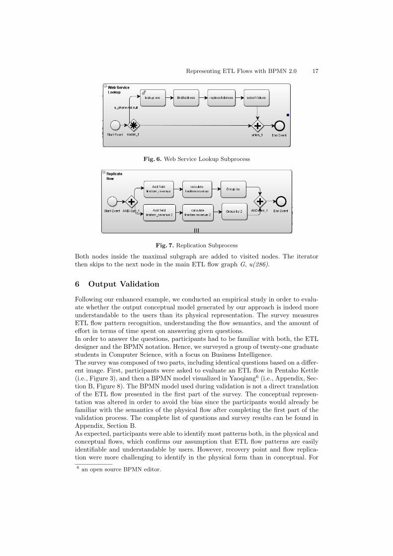
Fig. 6. Web Service Lookup Subprocess
Fig. 7. Replication Subprocess
Both nodes inside the maximal subgraph are added to visited nodes. The iteratorthen skips to the next node in the main ETL flow graph G, u(286).
6 Output Validation
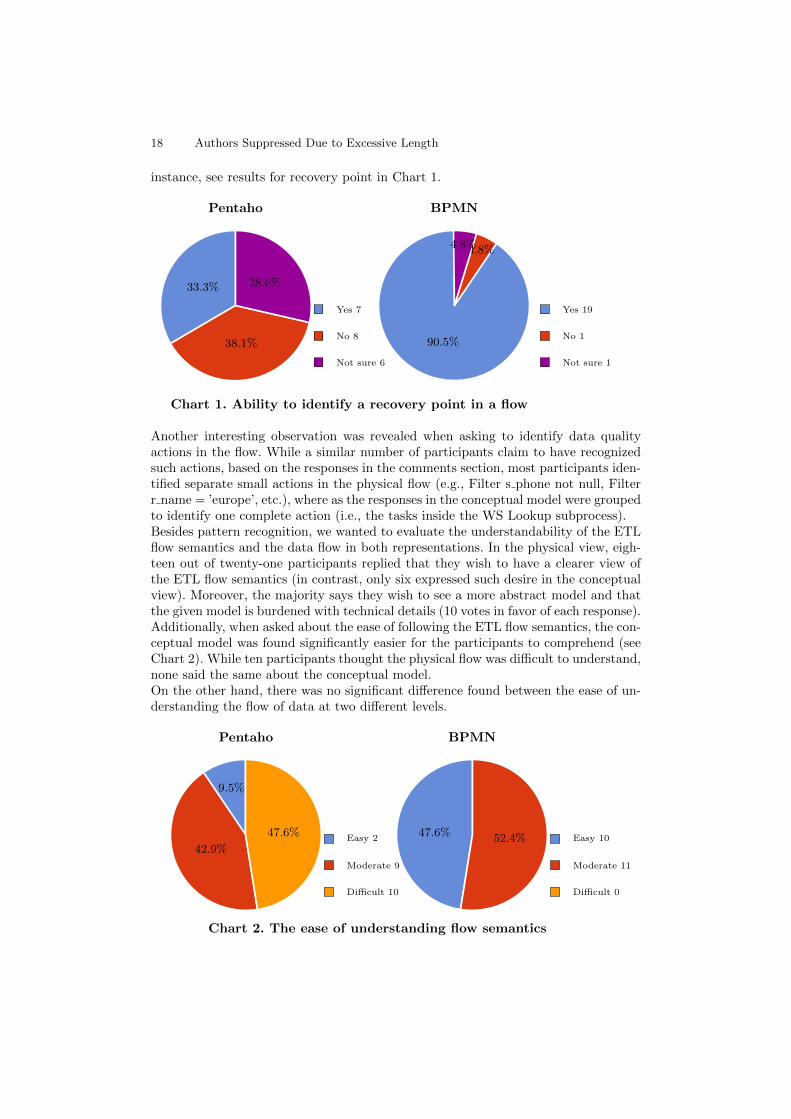
Following our enhanced example, we conducted an empirical study in order to evalu-ate whether the output conceptual model generated by our approach is indeed moreunderstandable to the users than its physical representation. The survey measuresETL flow pattern recognition, understanding the flow semantics, and the amount ofeffort in terms of time spent on answering given questions.In order to answer the questions, participants had to be familiar with both, the ETLdesigner and the BPMN notation. Hence, we surveyed a group of twenty-one graduatestudents in Computer Science, with a focus on Business Intelligence.The survey was composed of two parts, including identical questions based on a differ-ent image. First, participants were asked to evaluate an ETL flow in Pentaho Kettle(i.e., Figure 3), and then a BPMN model visualized in Yaoqiang6 (i.e., Appendix, Sec-tion B, Figure 8). The BPMN model used during validation is not a direct translationof the ETL flow presented in the first part of the survey. The conceptual represen-tation was altered in order to avoid the bias since the participants would already befamiliar with the semantics of the physical flow after completing the first part of thevalidation process. The complete list of questions and survey results can be found inAppendix, Section B.As expected, participants were able to identify most patterns both, in the physical andconceptual flows, which confirms our assumption that ETL flow patterns are easilyidentifiable and understandable by users. However, recovery point and flow replica-tion were more challenging to identify in the physical form than in conceptual. For
6 an open source BPMN editor.
18 Authors Suppressed Due to Excessive Length
instance, see results for recovery point in Chart 1.
Pentaho BPMN
Yes 7
No 8
Not sure 6
Yes 19
No 1
Not sure 1
33.3%
38.1%
28.6%
90.5%
4.8%4.8%
Chart 1. Ability to identify a recovery point in a flow
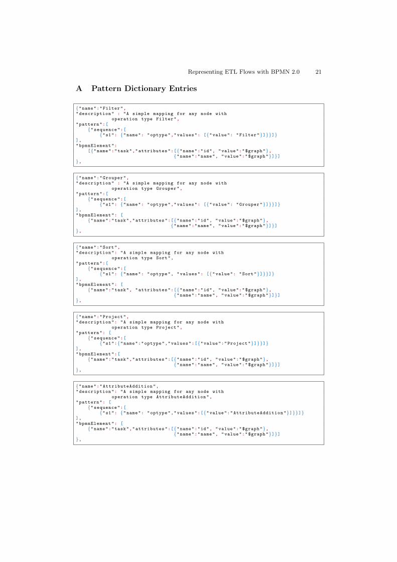
Another interesting observation was revealed when asking to identify data qualityactions in the flow. While a similar number of participants claim to have recognizedsuch actions, based on the responses in the comments section, most participants iden-tified separate small actions in the physical flow (e.g., Filter s phone not null, Filterr name = ’europe’, etc.), where as the responses in the conceptual model were groupedto identify one complete action (i.e., the tasks inside the WS Lookup subprocess).Besides pattern recognition, we wanted to evaluate the understandability of the ETLflow semantics and the data flow in both representations. In the physical view, eigh-teen out of twenty-one participants replied that they wish to have a clearer view ofthe ETL flow semantics (in contrast, only six expressed such desire in the conceptualview). Moreover, the majority says they wish to see a more abstract model and thatthe given model is burdened with technical details (10 votes in favor of each response).Additionally, when asked about the ease of following the ETL flow semantics, the con-ceptual model was found significantly easier for the participants to comprehend (seeChart 2). While ten participants thought the physical flow was difficult to understand,none said the same about the conceptual model.On the other hand, there was no significant difference found between the ease of un-derstanding the flow of data at two different levels.
Pentaho BPMN
Easy 2
Moderate 9
Difficult 10
Easy 10
Moderate 11
Difficult 0
9.5%
42.9%
47.6% 47.6% 52.4%
Chart 2. The ease of understanding flow semantics

Representing ETL Flows with BPMN 2.0 19
Finally, the majority of participants spent five or five to ten minutes evaluating thephysical model, where as most of them were able to evaluate the conceptual model inless than five minutes.This evaluation demonstrates that having a conceptual abstraction of an ETL flowhelps users understand the semantics of the flow with significantly less effort.
7 Conclusions and Future Work
In this thesis, we presented an automatic way to translate logical ETL flows intotheir conceptual BPMN representation. Having a conceptual abstraction of an exist-ing ETL flow increases its understandability and reusability within an organization.As an input format, we used an existing logical abstraction (i.e., xLM) that representsETL as a data flow graph. We first tried to identify all possible mappings betweenxLM and BPMN elements. However, we quickly realized that in order to allow ex-tracting more semantics from an ETL flow, we had to identify and define a set ofETL flow patterns that capture complex flow behavior. To automate the translationbetween the logical and conceptual ETL flow representations we defined a patterndictionary.We generalized the pattern dictionary to capture both, simple patterns (i.e., directmappings of ETL operations) and composite patterns that typically contain subflowsof ETL operations. The dictionary follows a formalized grammar and can be furtherextended to support new patterns and BPMN mappings.Finally, in this thesis, we proposed an algorithm that automatically discovers thechain of nested patterns contained in the ETL flow graph and provides a BPMNtranslation for every identified pattern. As a result, we are able to produce a BPMNrepresentation of an input ETL flow that can be further edited by a business user.Our contribution can be extended and enhanced in several directions. The first wouldbe to enhance pattern discovery by removing initial assumptions made in our ap-proach (i.e., strictly subsumed patterns and no two or more patterns matching thesame subgraph). Secondly, it would be important to develop a user-friendly tool thatfacilitates the translation of the logical ETL to its conceptual BPMN representationand encourages user interaction with the system. We believe that business users caneffectively specify their preference when two or more patterns intersect, validate thecorrectness of defined patterns, and share opinions about which patterns are moremeaningful than others.
References
1. van der Aalst, W.M.P.: Process mining: Overview and opportunities. ACM Trans. Man-agement Inf. Syst. 3(2), 7 (2012)
2. Akkaoui, Z.E., Zimanyi, E., Mazon, J., Trujillo, J.: A bpmn-based design and mainte-nance framework for ETL processes. IJDWM 9(3), 46–72 (2013)
3. Byrne, E.J.: Software reverse engineering: A case study. Software: Practice and Experi-ence 21(12), 1349–1364 (1991)
4. Conforti, R., Dumas, M., Garcıa-Banuelos, L., Rosa, M.L.: Beyond tasks and gateways:Discovering BPMN models with subprocesses, boundary events and activity markers.In: Business Process Management - 12th International Conference, BPM 2014, Haifa,Israel, September 7-11, 2014. Proceedings. pp. 101–117 (2014)

20 Authors Suppressed Due to Excessive Length
5. El Akkaoui, Z., Zimanyi, E.: Defining ETL worfklows using BPMN and BPEL. In: Pro-ceedings of the ACM Twelfth International Workshop on Data Warehousing and OLAP.pp. 41–48. DOLAP ’09, ACM, address = New York, NY, USA, keywords = conceptualmodeling, data warehouses, etl, logical modeling (2009)
6. Jovanovic, P., Simitsis, A., Wilkinson, K.: Engine independence for logical analytic flows.In: IEEE 30th International Conference on Data Engineering, Chicago, ICDE 2014, IL,USA, March 31 - April 4, 2014. pp. 1060–1071 (2014)
7. Kalenkova, A., de Leoni, M., van der Aalst, W.M.P.: Discovering, analyzing and en-hancing BPMN models using prom. In: Proceedings of the BPM Demo Sessions 2014Co-located with the 12th International Conference on Business Process Management(BPM 2014), Eindhoven, The Netherlands, September 10, 2014. p. 36 (2014)
8. Kuhn, A., Ducasse, S., Gırba, T.: Semantic clustering: Identifying topics in source code.Information & Software Technology 49(3), 230–243 (2007)
9. Li, J., Bose, R.P.J.C., van der Aalst, W.M.P.: Mining context-dependent and interac-tive business process maps using execution patterns. In: Business Process ManagementWorkshops - BPM 2010 International Workshops and Education Track, Hoboken, NJ,USA, September 13-15, 2010, Revised Selected Papers. pp. 109–121 (2010)
10. Lohmann, N., Verbeek, E., Dijkman, R.M.: Petri net transformations for business pro-cesses - A survey. T. Petri Nets and Other Models of Concurrency 2, 46–63 (2009)
11. Munoz, L., Mazon, J., Trujillo, J.: A family of experiments to validate measures forUML activity diagrams of ETL processes in data warehouses. Information & SoftwareTechnology 52(11), 1188–1203 (2010)
12. Oliveira, B., Belo, O.: BPMN patterns for ETL conceptual modeling and validation. In:Chen, L., Felfernig, A., Liu, J., Ra, Z. (eds.) Foundations of Intelligent Systems, LectureNotes in Computer Science, vol. 7661, pp. 445–454. Springer Berlin Heidelberg (2012)
13. OMG: Business process model and notation (BPMN) version 2.0. Tech. rep. (2011)14. Sartipi, K.: Software architecture recovery based on pattern matching. In: 19th Interna-
tional Conference on Software Maintenance (ICSM 2003), The Architecture of ExistingSystems, 22-26 September 2003, Amsterdam, The Netherlands. p. 293 (2003)
15. Shasha, D., Wang, J.T., Giugno, R.: Algorithmics and applications of tree and graphsearching. In: Proceedings of the Twenty-first ACM SIGACT-SIGMOD-SIGART Sym-posium on Principles of Database Systems, June 3-5, Madison, Wisconsin, USA. pp.39–52 (2002)
16. Skersys, T., Tutkute, L., Butleris, R.: The enrichment of BPMN business process modelwith SBVR business vocabulary and rules. CIT 20(3), 143–150 (2012)
17. Skoutas, D., Simitsis, A., Sellis, T.K.: Ontology-driven conceptual design of ETL pro-cesses using graph transformations. J. Data Semantics 13, 120–146 (2009)
18. Theodorou, V., Abello, A., Lehner, W., Thiele, M.: Quality measures for ETL processes.Concurrency and Computation: Practice & Experience (Special Issue) (2015)
19. Tsantalis, N., Chatzigeorgiou, A., Stephanides, G., Halkidis, S.T.: Design pattern de-tection using similarity scoring. IEEE Transactions on Software Engineering 32(11),896–909 (2006)
20. Vassiliadis, P., Simitsis, A., Baikousi, E.: A taxonomy of ETL activities. In: DOLAP2009, ACM 12th International Workshop on Data Warehousing and OLAP, Hong Kong,China, November 6, 2009, Proceedings. pp. 25–32 (2009)
21. Wilkinson, K., Simitsis, A., Castellanos, M., Dayal, U.: Leveraging business process mod-els for ETL design. In: Conceptual Modeling - ER 2010, 29th International Conferenceon Conceptual Modeling, Vancouver, BC, Canada, November 1-4, 2010. Proceedings.pp. 15–30 (2010)
22. Wills, L.M.: Automated program recognition by graph parsing. Ph.D. thesis (1992),http://hdl.handle.net/1721.1/6806
Representing ETL Flows with BPMN 2.0 21
A Pattern Dictionary Entries
{"name":"Filter","description" : "A simple mapping for any node with
operation type Filter","pattern":[
{"sequence":[{"s1": {"name": "optype","values": [{"value": "Filter"}]}}]}
],"bpmnElement":
[{"name":"task","attributes":[{"name":"id", "value":"$graph"},{"name":"name", "value":"$graph"}]}]
},
{"name":"Grouper","description" : "A simple mapping for any node with
operation type Grouper","pattern":[
{"sequence":[{"s1": {"name": "optype","values": [{"value": "Grouper"}]}}]}
],"bpmnElement": [
{"name":"task","attributes":[{"name":"id", "value":"$graph"},{"name":"name", "value":"$graph"}]}]
},
{"name":"Sort","description": "A simple mapping for any node with
operation type Sort","pattern":[
{"sequence":[{"s1": {"name": "optype", "values": [{"value": "Sort"}]}}]}
],"bpmnElement": [
{"name":"task", "attributes":[{"name":"id", "value":"$graph"},{"name":"name", "value":"$graph"}]}]
},
{"name":"Project","description": "A simple mapping for any node with
operation type Project","pattern": [
{"sequence":[{"s1":{"name":"optype","values":[{"value":"Project"}]}}]}
],"bpmnElement":[
{"name":"task","attributes":[{"name":"id", "value":"$graph"},{"name":"name", "value":"$graph"}]}]
},
{"name":"AttributeAddition","description": "A simple mapping for any node with
operation type AttributeAddition","pattern": [
{"sequence":[{"s1": {"name": "optype","values":[{"value":"AttributeAddition"}]}}]}
],"bpmnElement": [
{"name":"task","attributes":[{"name":"id", "value":"$graph"},{"name":"name", "value":"$graph"}]}]
},

22 Authors Suppressed Due to Excessive Length
{"name":"Distinct","description": "A simple mapping for any node with
operation type Distinct","pattern": [
{"sequence":[{"s1": {"name": "optype","values": [{"value": "Distinct"}]}}]}
],"bpmnElement": [
{"name":"task", "attributes":[{"name":"id", "value":"$graph"},{"name":"name", "value":"$graph"}]}]
},
{"name":"Rename","description": "A simple mapping for any node with
operation type Rename","pattern": [
{"sequence":[{"s1": {"name": "optype","values": [{"value": "Rename"}]}}]}
],"bpmnElement": [
{"name":"task","attributes":[{"name":"id", "value":"$graph"},{"name":"name", "value":"$graph"}]}]
},
{"name":"TopK","description": "A simple mapping for any node with
operation type TopK","pattern": [
{"sequence":[{"s1": {"name": "optype","values": [{"value": "TopK"}]}}]}
],"bpmnElement": [
{"name":"task","attributes":[{"name":"id", "value":"$graph"},{"name":"name", "value":"$graph"}]}]
},
{"name":"UserDefinedFunction","description": "A simple mapping for any node with
operation type UserDefinedFunction","pattern": [
{"sequence":[{"s1": {"name": "optype",
"values":[{"value":"UserDefinedFunction"}]}}]}],"bpmnElement": [
{"name":"task", "attributes":[{"name":"id", "value":"$graph"},{"name":"name", "value":"$graph"}]}]
},
{"name":"Router","description": "A simple mapping for any node with
operation type Router","pattern":[
{"sequence":[{"s1": {"name": "optype","values": [{"value": "Router"}]}}]}
],"bpmnElement": [
{"name":"complexGateway","attributes":[{"name":"gatewayDirection","value":"Unspecified"},
{"name":"id", "value":"$graph"},{"name":"name", "value":"$graph"}]}]
},

Representing ETL Flows with BPMN 2.0 23
{"name":"Union","description": "A simple mapping for any node with
operation type Union","pattern":[
{"sequence":[{"s1": {"name": "optype","values": [{"value": "Union"}]}}]}
],"bpmnElement": [
{"name":"parallelGateway","attributes":[
{"name":"gatewayDirection","value":"Converging"},{"name":"id", "value":"$graph"},{"name":"name", "value":"$graph"}]}]
},
{"name":"Merger","description": "A simple mapping for any node with
operation type Merger","pattern":[
{"sequence":[{"s1": {"name": "optype","values": [{"value": "Merger"}]}}]}
],"bpmnElement": [
{"name":"parallelGateway","attributes":[{"name":"gatewayDirection","value":"Converging"},
{"name":"id", "value":"$graph"},{"name":"name", "value":"$graph"}]},
{"name":"sequenceFlow","attributes":[{"name":"id", "value": "$graph"},
{"name":"sourceRef", "value":"$graph"},{"name":"targetRef", "value":"$graph"}]},
{"name":"task","attributes":[{"name":"name","value":"$create"},
{"name":"id", "value":"$create"}]}]},
{"name":"Voter","description": "A simple mapping for any node with
operation type Voter","pattern":[
{"sequence":[{"s1": {"name": "optype", "values": [{"value": "Voter"}]}}]}
],"bpmnElement": [
{"name":"eventBasedGateway","attributes": [{"name":"gatewayDirection","value":"Mixed"},
{"name":"id", "value":"$graph"},{"name":"name", "value":"$graph"}]}]
},
{"name":"Splitter","description": "A simple mapping for any node with
operation type Splitter","pattern":[
{"sequence":[{"s1": {"name": "optype","values": [{"value":"Splitter"}]}}]}
],"bpmnElement": [
{"name":"parallelGateway","attributes":[
{"name":"gatewayDirection","value":"Diverging"},{"name":"id", "value":"$graph"},{"name":"name", "value":"$graph"}]}]
},

24 Authors Suppressed Due to Excessive Length
{"name":"Join","description": "A simple mapping for any node with
operation type Join","pattern":[
{"sequence":[{"s1": {"name": "optype","values": [{"value": "Join"}]}}]}
],"bpmnElement":[
{"name":"parallelGateway","attributes":[
{"name":"gatewayDirection", "value":"Converging"},{"name":"id", "value":"$graph"},{"name":"name", "value":"$graph"}]},
{"name":"sequenceFlow","attributes":[
{"name":"id", "value": "$graph"},{"name":"sourceRef", "value":"$graph"},{"name":"targetRef", "value": "$graph"}]},
{"name":"task","attributes":[
{"name":"id", "value":"$create"},{"name":"name", "value":"$create"}]}]
},
{"name":"LeftOuterJoin","description": "A simple mapping for any node with
operation type LeftOuterJoin","pattern":[
{"sequence":[{"s1": {"name": "optype",
"values": [{"value":"LeftOuterJoin"}]}}]}],"bpmnElement":[
{"name":"parallelGateway","attributes":[{"name":"gatewayDirection", "value":"Converging"},
{"name":"id", "value":"$graph"},{"name":"name", "value":"$graph"}]},
{"name":"sequenceFlow","attributes":[{"name":"id", "value": "$graph"},
{"name":"sourceRef", "value":"$graph"},{"name":"targetRef", "value": "$graph"}]},
{"name":"task","attributes":[{"name":"id", "value":"$create"},
{"name":"name", "value":"$create"}]}]},
{"name":"TableInput","description": "A simple mapping for any node with
operation type TableInput","pattern":[
{"sequence":[{"s1": {"name": "optype","values": [{"value":"TableInput"}]}}]}
],"bpmnElement": [
{"name":"dataStore","attributes":[{"name":"id", "value":"$graph"},
{"name":"name", "value":"$graph"},{"name":"isUnlimited", "value":"false"}]},
{"name":"dataStoreReference","attributes":[{"name":"dataStoreRef", "value":"DS_n"},
{"name":"id", "value":"$graph"}]}]},

Representing ETL Flows with BPMN 2.0 25
{"name":"TableOutput","description": "A simple mapping for any node with
operation type TableOutput","pattern":[
{"sequence":[{"s1": {"name": "optype","values": [{"value":"TableOutput"}]}}]}
],"bpmnElement": [
{"name":"dataStore","attributes":[{"name":"id", "value":"DS_n"},
{"name":"name", "value":"$graph"},{"name":"isUnlimited", "value":"false"}]},
{"name":"dataStoreReference","attributes":[{"name":"dataStoreRef", "value":"DS_n"},
{"name":"id", "value":"$graph"}]}]},
{"name":"FileInput","description": "A simple mapping for any node with
operation type FileInput","pattern":[
{"sequence":[{"s1": {"name": "optype","values": [{"value":"FileInput"}]}}]}
],"bpmnElement": [
{"name":"dataStore","attributes":[{"name":"id", "value":"$graph"},
{"name":"name", "value":"$graph"},{"name":"isUnlimited", "value":"false"}]},
{"name":"dataStoreReference","attributes":[{"name":"dataStoreRef", "value":"DS_n"},
{"name":"id", "value":"$graph"}]}]},
{"name":"FileOutput","description": "A simple mapping for any node with
operation type FileOutput","pattern":[
{"sequence":[{"s1": {"name": "optype","values": [{"value":"FileOutput"}]}}]}
],"bpmnElement": [
{"name":"dataStore","attributes":[{"name":"id", "value":"$graph"},
{"name":"name", "value":"$graph"},{"name":"isUnlimited", "value":"false"}]},
{"name":"dataStoreReference","attributes":[{"name":"dataStoreRef", "value":"DS_n"},
{"name":"id", "value":"$graph"}]}]},
{"name":"XMLInput","description": "A simple mapping for any node with
operation type XMLInput","pattern":[
{"sequence":[{"s1": {"name": "optype","values": [{"value": "XMLInput"}]}}]}
],"bpmnElement": [
{"name":"dataStore","attributes":[{"name":"id", "value":"$graph"},
{"name":"name", "value":"$graph"},{"name":"isUnlimited", "value":"false"}]},
{"name":"dataStoreReference","attributes":[{"name":"dataStoreRef", "value":"DS_n"},
{"name":"id", "value":"$graph"}]}]},

26 Authors Suppressed Due to Excessive Length
{"name":"XMLOutput","description": "A simple mapping for any node with
operation type XMLOutput","pattern":[
{"sequence":[{"s1": {"name": "optype","values": [{"value": "XMLOutput"}]}}]}
],"bpmnElement": [
{"name":"dataStore","attributes":[{"name":"id", "value":"$graph"},
{"name":"name", "value":"$graph"},{"name":"isUnlimited", "value":"false"}]},
{"name":"dataStoreReference","attributes":[{"name":"dataStoreRef", "value":"DS_n"},
{"name":"id", "value":"$graph"}]}]},
{"name":"ExcelInput","description": "A simple mapping for any node with
operation type ExcelInput","pattern":[
{"sequence":[{"s1": {"name": "optype","values": [{"value": "ExcelInput"}]}}]}
],"bpmnElement": [
{"name":"dataStore","attributes":[{"name":"id", "value":"$graph"},
{"name":"name", "value":"$graph"},{"name":"isUnlimited", "value":"false"}]},
{"name":"dataStoreReference","attributes":[{"name":"dataStoreRef", "value":"DS_n"},
{"name":"id", "value":"$graph"}]}]},
{"name":"ExcelOutput","description": "A simple mapping for any node with
operation type ExcelOutput","pattern":[
{"sequence":[{"s1": {"name": "optype","values": [{"value":"ExcelOutput"}]}}]}
],"bpmnElement": [
{"name":"dataStore","attributes":[{"name":"id", "value":"$graph"},
{"name":"name", "value":"$graph"},{"name":"isUnlimited", "value":"false"}]},
{"name":"dataStoreReference","attributes":[{"name":"dataStoreRef", "value":"DS_n"},
{"name":"id", "value":"$graph"}]}]},
{"name":"WSLookup","description": "A simple mapping for any node with
operation type WSLookup","pattern":[
{"sequence":[{"s1": {"name": "optype","values": [{"value":"WSLookup"}]}}]}
],"bpmnElement": [
{"name":"task","attributes":[{"name":"id", "value":"$graph"},
{"name":"name", "value":"$graph"}]}]},

Representing ETL Flows with BPMN 2.0 27
{"name":"recoveryPoint","description": "A user defined control -flow pattern that
identifies check -pointing in an ETL flow","pattern":[
{"sequence":[{"s1":
{"name": "optype","values": [{"value": "Splitter"},{"value": "Router"}]}}]},
{"parallelFlows":[{"flow1":[
{"repeat": "=1","sequence":[
{"s1":{"name":"$whiteList","values": []}},{"s2":{"name":"type",
"values": [{"value":"Datastore"}]}}]}]}]}],"whiteList":[{"name": "optype",
"values": [{"value":"UserDefinedFunction"}]}],"bpmnElement":[{"name":"textAnnotation",
"attributes":[{"name":"id", "value":"$create"},{"name":"textFormat", "value":"text/plain"}],
"text":"recoveryPoint"},{"name":"association","attributes":[{"name":"associationDirection", "value":"None"},
{"name":"id", "value":"$create"},{"name":"sourceRef", "value":"$graph"},{"name":"targetRef", "value":"$create"}]}]
},
{"name":"compensation","description": "A user defined control -flow pattern
to depict compensation action operationsin an ETL flow",
"pattern":[{"sequence": [
{"s1":{"name": "optype","values": [{"value": "Splitter"},
{"value": "Router"}]}}]},{"parallelFlows":[
{"flow1":[{"repeat": "=1","sequence":[
{"s1":{"name":"optype","values": [{"value":"UserDefinedFunction"}]}},
{"s2":{"name":"type","values":[{"value":"Datastore"}]}}]}]}]}],"whiteList": [{"name": "optype",
"values": [{"value":"UserDefinedFunction"}]}],"bpmnElement":[
{"name":"subProcess","attributes":[{"name":"name", "value":"$create"},
{"name":"id", "value":"$graph"},{"name":"completionQuantity", "value":"1"},{"name":"isForCompensation", "value":"true"},{"name": "startQuantity", "value":"1"},{"name": "triggeredByEvent", "value":"false"}]}]
},
Currently, xLM does not support any operation types that can depict encryptionor compression that are often used in the ETL flow before chekpointing or otheroperations used as compensation actions, hence both patterns (i.e., recoveryPointand compensation) use the UserDefinedFunction operation to express such behavior.

28 Authors Suppressed Due to Excessive Length
{"name":"replication","description": "A user defined control -flow pattern
that identifies replication in an ETL flow","pattern":[
{"sequence":[{"s1":
{"name": "optype","values": [{"value": "Splitter"},{"value": "Router"}]}}]},
{"parallelFlows":[{"flow1":[
{"repeat": ">1","sequence":[
{"s1":{"name":"$anyType","values":[{"value":"$anyValue"}]}}]}]}]},
{"sequence":[{"s1":{"name": "optype","values": [{"value": "Union"}]}}]}
],"blackList": [{"name": "optype","values": [{"value": "Union"}]}],"bpmnElement":[
{"name":"subProcess","attributes":[{"name":"name", "value":"$create"},
{"name":"id", "value":"$graph"},{"name":"completionQuantity", "value":"1"},{"name":"isForCompensation", "value":"false"},{"name": "startQuantity", "value":"1"},{"name": "triggeredByEvent", "value":"false"}]},
{"name":"multiInstanceLoopCharacteristics","attributes":[{"name": "behavior", "value": "All"},
{"name":"isSequential", "value":"false"}]}]},
{"name":"externalDataValidationWS","description": "A user defined pattern that identifies
data quality actions in an ETL flowdata input via a web service call",
"pattern":[{"sequence":[
{"s1":{"name": "optype","values": [{"value": "Router"}]}}]},
{"parallelFlows":[{"flow1":[
{"repeat": "=1","sequence":[
{"s1":{"name":"$anyType","values": [{"value":"$anyValue"}]}},{"s2":{"name":"optype","values": [{"value":"WSLookup"}]}},{"s3":{"name":"$anyType",
"values":[{"value":"$anyValue"}]}}]}]}]},{"sequence":[
{"s1":{"name": "optype","values": [{"value": "Union"}]}}]}
],"blackList": [
{"name": "optype","values": [{"value": "Union"}]}],
"bpmnElement":[{"name":"subProcess","attributes":[
{"name":"name", "value":"$create"},{"name":"id", "value":"$graph"},{"name":"completionQuantity", "value":"1"},{"name":"isForCompensation", "value":"false"},{"name": "startQuantity", "value":"1"},{"name": "triggeredByEvent", "value":"false"}]}]
}

Representing ETL Flows with BPMN 2.0 29
B Validation Process and Results
This survey evaluates the understanding of the ETL flow semantics first based on aphysical flow in Pentaho Kettle and then a conceptual representation of a similar flowin BPMN.
B.1 Survey Questions
1. Are you able to identify any data cleaning/validation action in the ETL flow?(Yes/No/Not Sure).If yes, please point out every occurrence in the flow.
2. Can you identify if the flow contains a recovery point? (Yes/No/Not Sure).(A recovery point is a checkpoint of the ETL state at a fixed point in the flow.)If yes, please point out every occurrence in the flow.
3. Can you clearly see when two (or more) input flows are being merged? (Yes/No/NotSure).If yes, please point out every occurrence in the flow.
4. Can you identify if any part of the flow is replicated? (Yes/No/Not Sure).If yes, please point out every occurrence in the flow.
5. Do you wish to have a more clear view of the flow semantics? (Yes/No/Not Sure).If yes, explain why.– The model is burdened with technical details.– I wish to see a more abstract model.– I wish to see a more concise model.
6. How easy was it to follow the flow of data? (Easy/Moderate/Difficult).7. How easy was it to understand the semantics of the ETL flow? (Easy/Moder-
ate/Difficult).8. How much time did you spend evaluating the model in order to truthfully answer
the questionnaire? (Less than 5 minutes/ 5 minutes/ 5-10 minutes/ 10-15 minutes/More than 15 minutes).
B.2 BPMN Model
The BPMN model depicted in Figure 8 was used during the evaluation process.
Fig. 8. BPMN Model Used for Validation

30 Authors Suppressed Due to Excessive Length
B.3 Results Summary
Pentaho BPMN
Yes 15
No 2
Not sure 4
Yes 13
No 5
Not sure 3
71.4%
9.5%
19%
61.9%23.8%
14.3%
Chart 3. Identifying data quality actions
Pentaho BPMN
Yes 21
No 0
Not sure 0
Yes 19
No 0
Not sure 2100.0% 90.5%
9.5%
Chart 4. Identifying merged data inputs
Pentaho BPMN
Yes 9
No 9
Not sure 3
Yes 19
No 2
Not sure 0
42.9%
42.9%
14.3%
90.5%
9.5%
Chart 5. Identifying replication

Representing ETL Flows with BPMN 2.0 31
Pentaho BPMN
Yes 3
No 15
Not sure 3
Yes 9
No 11
Not sure 1
14.3%
71.4%
14.3%
42.9%
52.4%
4.8%
Chart 6. Ease of following the flow of data
Pentaho BPMN
<5 min. 6
5min. 7
5-10min. 7
>15min. 1
<5 min. 12
5min. 6
5-10min. 3
28.6%
33.3%
33.3%
4.8%
57.1% 28.6%
14.3%
Chart 7. Model evaluation time