reproduced fromc i best available copy c t.the'isgott (2nd edition) as a valuable guide for...
TRANSCRIPT
N ~~U.S. Dcr cptof1 Trarn 5:'o r& c)*OA
Reproduced FromCI Best Available Copy
TP- C
T.
ThiTh docmet m)foe aprve
ffor. public release rind sale; its

"TECHNICAL REPORT STANDARD TITLE PAGE
"" 1. Report No. i 2. Government Accession No. 3. Recipient's Catalog No.
* 16732/0001 HQS 84
4. Title and Subtitle Marine Casualty Report 5. Report DateI Maine asuaty Rport6 February 1985-. SS AMERICAN EAGLE, O.N. 278827; Explosion in the Gulf
of Mexico on 26 February 1984 and subsequent sinking on r-MInrioC27 February 1984 with multiple loss of life"7. Author(s) 8. Performing Organization Report No.
0001 HQS 84
9. Performing Orgonization Name and Address 10. Work Unit No.•.% U. S. Coast Guard
U. S. oast uard. Contract nr Grant No."* Washington, D.C. 20593
13. T .,po of Report and Period Covered
12. Sponsoring Agency Name and Addres, MARINE CASUALTY REPORT
Commandant (G-MMI-1/24) 27 February 1984
U. S. Coast Guard 14. Sponsoring Agency CodeWashington, D.C.' 20593
15. Supplementary Notes
-7"
"-* 16. Abstract
"At 1045 February 26, 1984, the American tankship SS AMERICAN EAGLE suffered amajor cargo tank explosion while enroute in ballast from Savannah, Georgia toOrange, Texas. The explosion occurred while several crew members were cleaning"and gas-freeing the number 3 center cargo tank of the last cargo of gasoline."Although the SS AMERICAN EAGLE suffered major structural damage, the vessel
"'* remained afloat until February 27, 1984, when the vessel broke up and the Master* ordered the crew to abandon ship. The surviving crew members were rescued by
three offshore supply vessels and a Coast Guard helicopter. As a result of theexplosion, 3 crewmen lost their lives and 4 were injured. During the abandon-ment and rescue efforts I additional crew members lost their lives and 2 remainmissing and are presumed dead; also 5 more crew members were injured. Theproximate cause of the casualty was the introduction of steam into number 3cente. cargo tank through an ungrounded air mover with a plastic sleeveattached. The use of steam resulted in an electrostatic discharge which ignited"the hydrocarbon vapors in the number 3 center cargo tank. The Coast Guard hasissued warnings regarding the use of steam and portable ver-uri-type blowers in
* nongas-free atmospheres.
This report contains the U. S. Coast Guard Marine Board of Investigation Reportand the Action taken by the Commandant to determine the proximate cause of the"casualty and provide a response to the recommendations to prevent recurrence.
17. Key Words Air mover, explosion, tanker, is. Distribution Statement
gas-freeing, electrostatic charge, ISGOTT, This document is available to The publicinert gas systems, tank washing machines, through the National Technical Informationsteam, venturi-type blowers, butterworth Service, Springfield, Virginia 22121plates, ventilator, static electricity
19. Security Classif. (oF this report) 20. Security Classif. (of this page) 21. No. of Pages 22. Price
UNCLASSIFIED UNCLASSIFIED
"Form DOT F 1700.7 I8.65-)
SS AMERICAN EAGLE, O.N.278327, EXPLOSION INTHE GULF OF MEXICO, ON 26 FEBRUARY 1984 AND
SUBSEQUENT SINKING ON 27 FEBRUARY 1984WITH LOSS OF LIFE
TABLE OF CONTENTS
Page
PART I
ACTION BY THE COMMANDANT U. S. COAST GUARD
Remarks ..... ........ ........................... ...... ... . ...- 1Comments on Conclusions ............... 2Action, Concerning the Recommendations..................... 3
PART II
MARINE BOARD OF INVESTIGATION
Findings of Fact ................ ...................... 1Conclusions....................................... 34Recrnmendat ions ..................................... ..... 39
.4-J
IAccession For
SDTIC TAR
Distribution/
Avalth1T lity codes
01(
Avail noi/or d
Dist r a'utionvAi / l.t ods#.~. °,I

I
IPART I
\fl
-A
I
S.
USLDepartment Commandant Washington. DC 20593Of TransPortation/IUnited States'Coast Guard Staff symbo: C-C/22
Phone: (202) 426-2380Unitd StatesCoast Guard I
16732/-MERICAN EAGLE8 July 1985
Commandant's Action
on
The Mirine Board uf Investigation convened to investigate the cir-cumstances surrounding the explosion on board the SS AMERICAN EAGLE,O.N. 278317 in the Gulf of Mexico on February 26, 1984, and subse-quent sinking on February 27, 1984# with multiple loss of life.
The report of the marine board of investigation convened to investigate thesubject casualty has been reviewed and the record, including the findings offact, conclusions and recommendations, ,is approved subject to the followingcomment s:
REMARKS
1. In concurrence with the board, the proximate cauie of Lhe casualty was theintroduction of steam into number 3 center cargo tank through an ungroundedair mover with a plastic sleeve attached. The use of steam resulted in anelectrostatic discharge which ignited the hydrocarbon vapors in the number 3center cacgo tank. However, the specific origin of the electrostatic dis-charge cannot be determined. Although the discharge may have been from theair mover to the deck as concluded by the board, the possibility that thedischarge may have been from the plastic sleeve to the tank or from a vaporcloud to the tank cannot be eliminated. This casualty illustrates the needfor personnel involved in tank cleaning and tank venting operations to beaware of the dangers of static electricity and to observestringent safetyprecautions which is paramount in preventing this type of casualty.
2. Contributing causes to the rapid breakLp and sinking of the AMERICAN EAGLEinclude a combination of the following:
(a) the rapid deterioration of weather and sea conditions on February 27,1984; and
(b) the failure to secure all cargo tank hatches and Butterworth platesafter the explosion.
3. Contributing causes to the loss of life include a combination of thefollowing:
.................................... .. .. .. ......

a. the adverse weather and sea-conditions which held the lifeboat in the-- -lee of the wind-driven ship. This situation instilled fear in the crew
members that the ship would roll over the lifeboat which prompted them to jumpinto the water; and
b. the delay in the evacuatiou of nonessential personnel from the vesselafter the explosion occurred. A thorough assessment of the extent of struc-tural damage to the vessel, which was not conducted after the explusion', mayhave led to a more timely and orderly evacuation.
COMMENTS CN CONCLUSIONS
1. Conclusion 12: That there is some question as to whether all precautionsassociated with the Lamb air mover ventilator were being observed. The warninglabel states that the device should be grounded; however, testimony verifiedthat the device was not properly grounded.
Comment: This conclusion is concurred with. The air mover should have beenproperly rounded in accordance with the manufacturer's instruction in thewarning label. However, proper grounding of the air mover would not haveeliminated the risk of electrostatic discharge from the plastic sleeve or thevapor cloud.
2. Conclusion 16: That the Chief Mate and the Master should have been aware ofthe hazards associated with introducing steam into nongas free tanks as statedin the International Safety Guide for Oil Tankers and Terminals (ISGOTT).
Comment: This conclusion is concurred with. Chapter 8 of the ISGOTT on tankcleaning and gas freeing clearly warns against injecting steam into tanks wherethere is any risk of the presence of a flammable atmosphere. Contrary to theguidance contained in the ISGOTT, the Mine Safety Appliances Company (MSA) datasheet provided as Appendix A to the board's report indicates that the air moveris suitable for use with steam in the blower mode in potentially exnlniv•atmospheres when properly grounded. A copy of th'- rvuvrc will be provided toMSA with a recommendation that literptu4, describing the air mover be revised toreflect the hazards of introducing steam into a flammable atmosphere.
3. Conclusion 22: That had the Master secured all cargo tank hatches, Butter-worth plates and watertight doors at the time he ordered all valves to be shut,the vessel may not have sunk as rapidly, allowing more time for an orderlyevacuation.
Comment: This conclusion is concurred with in part. Neither the findings offact nor the record established that the watertight doors were not secured noris it clear to what extent, if any; the watertight doors influenced the outcomeof this ctsualty.
4. Conclusion 42: That the American Foreign Steamship Company did not have aformal safet~r program.
2
Comment: This conclusion is not concurred with in that it is not supported by
the findings of fact.
ACTION CONCERNING THE RECOMMENDATIONS
1. Recommendation 1: That the Coast Guard issue precautions on the use ofsteam in tanks that are not gas free. Steam should not be injected into nongasfree tanks. All personnel involved in tank cleaning/gas freeing operationsshould be made aware of the hazards.
Recommendation 2: That the Coast Guard publish a safety advisory to alertseamen who serve aboard tank vessels of the need to ground cargo tank venti-lating blowers. This is particularly important with respect to portable venturiair mover ventilators as used aboard the AMERICAN EAGLE.
Action: Recommendations 1 and 2 are concurred with. Within days after thecasualty, the Coast Guard issued a service-wide warning regarding the use ofportable venturi a'r mover blowers or exhaust units in nongas free'atmospheres.Specifically, the warning addressed the need to ensure a positive grounding ofthe device and the hazards of using steam to ventilate tanks due to thegeneration of electro-static charges. All the Coast Guard field offices towhich the warning was addressed disseminate this type of information to theaarine industry within their area of responsibility via numerous methods. Thiswarning was also published in the June 1984 "Proceedings of the Marine SafetyCouncil" which has a substantial distribution. The preliminary findings on thiscasualty and the associated precautions mr• also disseminated internationally.
2. Recommendation 3: That the T!NOTT be endorsed by the Coast Guard and that acopy be required aboard all U.S. tank vessels and those foreign tank vesselsentering U.S. waters.
Action: The intent of this recommendation is concurred with. The InternationaliGitime Organization (IMO) Subcommittee on Fire Protection recently recognizedthe'ISGOTT (2nd edition) as a valuable guide for tank cleaning procedures on
tank vessels not fitted with inert gas systems (IGS). The Coast Guard concurs
with this assessment of the ISGOTT by the IMO Subcommittee and intends torefereuce ISGOTT in a forthcoming revision to the fire protection regulations.
3. Recommendation 4: that consid&ration be given to requiring the inerting ofcargo tanks containing flammable products such as gasoline. Present regulations
only require inerting of cargo tatiks containing crude oil on existing vessels oftonnages similar to the AMERICAN EAGLE.
Action:. The intent of this recommendation is concurred with. The rcquirementfor IGS on all vessels carrying crude oil or product such as gasoline has beenconsidered on naticnal and international levels. The applicable regulations in46 CFR 32.53 correspond to the international standards as published in the
International Convention for the Safety of Life at Sea, 1974, as amended. Tankvessels currently required to have an IGS include all crude oil 'carriers, new
3
and existing, of 20,000 dead weight tons (DWT) or more; all existing productcarriers of 40,000 DWT or more; and all existing product carriers between 20,000DWT and 40,000 DWT with high cipacity (60 cubic meters per hour) tank washingmachines. Existing product carriers less than 40,000 DWT with low capacity tankwashing machines are not required to have IGS. The AMERICAN EAGLE falls withinthe latter category and was not required to have IGS.
When the international community considered requiring IdS on existing productcarriers in the 20-40,000 DWT range, it was felt that these ships had a rela-tively good safety record and that introductiun of IGS piping and associatedequipment on an existing vessel could potentially prove to detriment instead ofcontribute to safety. The IMO Subcommittee on Fire Protection has beenperiodically reviewing serious tank vessel casualties and will continue to do sowith a view toward reevaluation of the IGS requirements.
4. Recommendation 5: That the use of portable venturi air mover ventilators,when operated in the blower mode, be prohibited in any spaces which are not gasfree.
Action: This recommendation is not concurred with. There is no evidence toindicate that the air mover, if used properly, is unsafe in a nongas freeatmosphere. However, in such an atmosphere, certain precautions are appro-priate. As prescribed by the manufacturer and indicated by a warning latel,proper use of the air mover requires grounding the device. Although the MSA airmover data sheet indicates that it may be used with either air or steam, thehazards involved with introducing steam into a nongas free atmosphere arewell-known and discussed in various publications including the ISGOTT, a copy ofwhich was aboard the vessel. Additionally, the use of a plastic sleeve provideda nonconductive surface on which the static charge could be accumulated. Thecasualty most likely would not have occurred had appropriate attention engiven to these concerns.
5. Recommendation 6: That portable venturi air mover ventilators be used inaccordance with provided warning labels.
Action: This recommendation is concurred with. Due caution should always beexercised to observe the manufacturer's safety warnings, mariners engaged intank cleaning should also be familiar with authoritative pubii'cations providingguidance and safety information on this subject.
6. Recommendation 7: That manufacturers of portable venturi air mover venti-lators provide a practical and positive method of grounding these devices.
Action: This recommendation is concurred with. Although normal placement ofmetal equipment on a deck cleared of high resistance materials such as gasketswill norm'ally provide an adequate leakage path to eliminate an electrostaticdischerge, this recommendation will be forwarded to MSA and other manufacturersof portable venturi air mover ventilators for their consideration. Ultimately,the equipment operator is responsible for ensuring that all safety precautionsincluding grounding of the equipment are observed.
7. Recommendation 8: That this report be given wide dissemination to themarine industry by means of the Proceedings of the Marine Safety Council after
4¢
.........- .- ~,-.- .
final action by the Commandant and the National Transportation Safety Board.This marine board believes that by publicizing the factors, which led to thisccsualty, many mariners will relate them to their own shipboard operations andperhaps recognize and correct potential hazards.
Action: This recommendation is concurred with. This report will be given widedissemination. An appropriate article describing the various factors which ledto this casualty will be published in the "Proceedings of the Marine SafetyCouncil."
Admiral, U. S. C oast GuardICommandant
I.-
!
5
S-• . -, '. - :/ - - : .- ,- -:.'. : .. -,' ,''''- '•" ,.•*•.•• '2 ,. '-.2 •,,, ,-/ . • -,,,-. / • % -'• .: .
- - - .. .'.-.

PART II
ItI
0 ItVTi v t
I YJ
iv r 1(
TABLE OF CONTENTS
FINDINGS OF FACT
PAGE
Preliminary Statement 1Vessel Data 2Record of Dead, Missing, and Injured 3Vessel Description5Last Voyage 7'The Casualty 12The Evacuation and Rescue 20
ANALYSIS
Weather 26Explosion 26Flares 29Stability and Strength Calculations 30Safety Advisory 30Lifeboat Lowering 31Coast Guard Response 31Structural Damage 33
FIGURES 33-1
CONCLUSIONS 34
RECOMMENDATIONS 39
APPENDICES
A. MSA data sheet 26r00-01, Lamb Air-Mover Ventilator
B. Excerpts from second edition of International SafetyGuide for Tankers and Terminals (ISGOTT)
C. Report on Stability and Strength Calculationsof the AMERICAN EAGLE
SUSDeportment _of Trans ortatnioi, R(n
COMMANDER (m) 51 S.W. 1st AvenueUni•d Stades [Th• Seventh Miami, FLcOOSGUOr lCoast Guard District 33130
16732/AMERICAN EAGLE6 February 1985
From: U. S. Coast Guard Marine Board of InvestigationTo: Commandarit (G-MMI)
Subject: SS AMERICAN EAGLE, O.N. 278327; explosion on board on26 February 1984, and subsequent sinking in the Gulf of Mexico on27 February 1984, with loss of life.
FINDINGS OF FACT
1. At or about 1045 (all times are +6 zone description, unlessotherwise noted, and are based on a 24 hour clock) on 26 February"1984, the U.S. tankship AMERICAN EAGLE, on a ballast voyage,suffered a major cargo tank explosion approximately 110 miles"South-Southwest of Grand Isle, Louisiana. Three crewmen were"killed and four were injured. The AMERICAN EAGLE suffered majorstructural damage in way of cargo tanks #2, #3 and #4 as a resultof the explosion. The vessel remained afloat, after theexplosion, with no appreciable change in list or trim. Duringthe afternoon of 27 February 1984 the drifting AMERICAN EAGLE wassetting down on several oil drilling rigs anchored in the area.To prevent the AMERICAN EAGLE from colliding with one of the oilrigs, an anchor-handling supply boat attempted to tow theAMERICAN EAGLE, stern first, clear of the anchored rigs. Approk-"imately 30-45 minutes after the towing operation commenced, thebow section of the AMERICAN EAGLE began to break away, at which"time the tow line was cut. When the bow started to break away,the Master ordered the crew to abandon ship. The crewmen enteredthe starboard aft #3 lifeboat. The boat was lowered, however itstopped short of the water and could not be lowered the remainingdistance to the water. Several of the crewmembers jumped fromthe boat, those remaining in the boat operated the releasing gearand the boat dropped into the water. Difficulty was experiencedin getting the boat away from the ship, so the remaining peoplejumped into the water from the lifeboat. All of the survivingcrewmembers, with the exception of two, were eventually recoveredfrom the water, either by the three offshore supply vessels"standing by or by the Coast Guard helicopter on scene. The sternsection of the AMERICAN EAGLE sank at approximately 1735 thatsame day. The bow section remained afloat for some time andpresumably sank during the night. As a result of this casualtyfive crewmen lost their lives, two crewmen remain missing andare presumed dead, and nine crewmen were injured.
..................... .-,J-.d..-,-o

2. Vessel data:Name
AMERICAN EAGLEOfficial number 478327"Service Oil tanker"Gross Tons 205t0
"Net tons 12662"Deadweight tons 33051Length overall 3305 eLength (between
"perpendiculars) 630.00 feetBreadth (molded) 90.00 feetDepth (molded) 45.25 feetPropulsion Steam turbo-reduction"Horsepower 13600Homeport New York, New YorkOwner American Foreign
Steamship Corp.80 Broad StreetNew York, NY 10004"Operator American ForeignSteamship Corp.80 Broad StreetNew York, NY 10004Whee built 17 March 1959.Where built Sparrows Point, Maryland"Built by Bethlehem SteelMseCorporation
Master Francis P. Powers130 Lanford RoadSpartanburg, SC 29301Age
"License 6?Master, steam and motor vessels,any gross tons upon oceans," iealso radar observer"License number 008307Issue 4-6Merchant Mariners Document Z-112741 2Coast Guard Certificate of Inspection data:
PDate of issue 22 July 1983SPlace of Issue Port Arthur, Texas"Expiration date 22 July 1985Drydocked Norfolk, Va (hauled out 14 Jun 83)'Pt Arthur, TX (completed 22 Jul 83)
Cargo Ship Safety Equipment Certificate:aIsued by U.S. Coast GuardlDate of issue 22 July 1983SPlace of issue Port Arthur, TexasExpiration date 22 July 1985
2

"Record of dead, missing, and injured
The following crewmembers were killed as a result of the explo-"sion on 26 February 1984.
HOME NEXT OF"NAME POSITION AGE ADDRESS KIN
MALLON Chief Mate 62 Zion Montgomery Road Wife"Edward. J. Route #1 Box 58-D
MMD# 274267 Neshanic Station CharlotteN.J. 08853
CAMPBELL Bosun 48 P.O. Box 59 WifeJack R. Carrabelle
MMD# 400-44-1698 FL, 32332 Agnes
CARTER Pumpmian 60 Route #1 Box 1-A WifeRoy D. Sycamore
MMD# 257-38-3526 GA, 31790 Flora
The following crewmembers died after abandoning the AMERICANEAGLE on 27 February 1984.
HOME NEXTSNAME POSITION AGE ADDRESS OF KIN
- FOTOPOULOS Steward 62 14275 Hampton Drive Son"Andrew Turah
MMD# 1172037 Montana Andrew
SYLVIA Messman/ 59 134 Blackmer St. Wife. Antone G. Utility New Bedford
"MMD# 431323-DI MA, 02744 Mary
"The following crewmembers are missing and presumed dead;
HOME NEXT OFNAME POSITION AGE ADDRESS KIN
BURNEY Able Seaman 56 3013 Highway 301 Wife•..Steger R. Box I
"" MMD# 263-32-7196 Riverview MildredFL, 33561
-7
WARREN Ordinary 55 1175 W. Third Street WifeEarsel Seaman Jacksonville
MMD# 721-16-1357 FL, 32209 Beatrice
3†††††††††*!*
L6
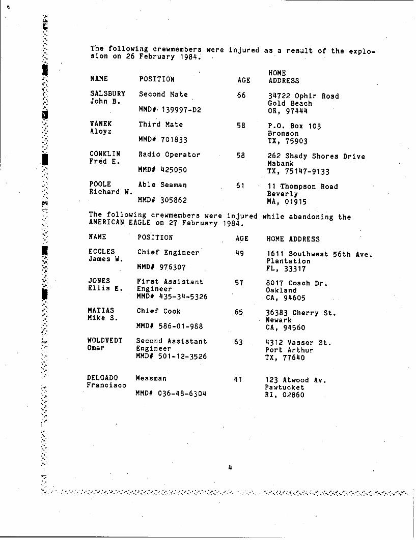
The following crewmembers were injured as a result of the explo-sion on 26 February 1984.
HOMENAME POSITION AGE ADDRESS
SALSBURY Second Mate 66 34722 Ophir RoadJohn B. Gold Beach
MMD# 139997-D2 OR, 97444
"VANEK Third Mate 58 P.O. Box 103"* Aloyz BronsonMMD# 701833 TX, 75903
"CONKLIN Radio Operator 58 262 Shady Shores DriveFred E. Mabank
MMD# 425050 TX, 75147-9133
"POOLE Able Seaman 61 11 Thompson RoadRichard W. Beverly
MMD# 305862 MA, 01915The following crewmembers were injured while abandoning theAMERICAN EAGLE on 27 February 1984.
NAME POSITION AGE HOME ADDRESS
ECCLES Chief Engineer 49 1611 Southwest 56th Ave.James W. Plantation
MMD# 976307 FL, 33317JONES First Assistant 57 8017 Coach Dr."Ellis E. Engineer Oakland
MMD# 435-34-5326 CA, 94605
r. MATIAS Chief Cook 65 36383 Cherry St.Mike S. Newark
MMD# 586-01-988 CA, 94560
WOLDVEDT Second Assistant 63 4312 Vasser St.Omar Engineer Port Arthur
MMD# 501-12-3526 TX, 77640
DELGADO Messman 41 123 Atwood Av.Francisco Pawtucket
MMD# 036-48-6304 RI, 02860
' 4
"-''- o "".- "'.-.'''•'.' "''-.-''•J'.- -'"- -""';'2 "" .. '"-- .". . .- -.. • ,• . .4
Vessel description:
4. The AMERICAN EAGLE was of steel construction and had a twohouse tankship configuration, which was typical for tankshipsbuilt at that time. The midships (forward) house contained thenavigating bridge, radio room, and quarters for the deck offi-cers. This house consisted of three decks and was centered overthe #3 and #4 cargo tanks. The bridge deck (lower most deck)contained the ship's office, officer's lounge, chief mate's dayroom, chief mate's stateroom, owner's stateroom, and stateroomsfor three other mates. The upper bridge deck (second deck up)contained the Captain's office, Captain's stateroom, radio room,radio operator's stateroom, and several small rooms. The radioroom was located on the port side aft. The navigating bridgedeck contained the wheelhouse, gyro and chartroom (one space),and the Captain's sea cabin. An enclosed shelter deck area waslocated on the main. deck below the lower, most deck of the house.This shelter deck area housed a 40 ton potable water tank,Butterworth and cargo hose storage racks, Bos'n stores, matesstores, and a slop chest. There were eleven (11) Butterworthopenings for the #3 and #4 cargo tanks located within the shelterdeck area.
5. The after house contained quarters for the remainder of thecrew, as well as the galley, officer's mess, and crew's mess. Itwas located directly over the machinery spaces. The main deckcontained quarters for the unlicensed personnel.. The poop deckcontained quarters for the licensed engineers, steward, cooks,bosun, and pumpman. The officer's mess and crew's mess were bothlocated on the poop deck forward. The officer's mess was locatedon the starboard side and the crew's mess was on the port side,with the galley located on the centerline between the messes.
I The two mess rooms were connected by the pantry, which is locateddirectly aft of the galley. The pantry provided open communica-tion between the two mess rooms.
6. The machinery spaces consisted of the engine room and boilerroom, with the engine room located forward of the boiler room.U These space. contained the boilers, main propulsion turbines andreduction gears, ships service generators, and necessary asso-
- ciated auxiliary machinery.
. 7. The AMERICAN EAGLE was a dedicated product carrier with a* cargo capacity of 280,455 barrels. The ship was divided into
ten cargo compartments. Each of the 'en compartments containeda center tank with port and starboard wing tanks for a total ofthirty individual cargo tanks. These thirty tanks were groupedinto four sections with, each section being served by individualdischarge and loading pipelines. Each section was capable ofbeing loaded or discharged independently, using four individualcargo pumps. It was also possible to cros's connect any of the
7 cargo sections and/or tanks. All of the cargo tanks wereequipped with heating coils. Venting of the cargo tanks was"accomplished by independent pressure/vacuum (P/V) valves which
5
5
.............

* were fitted to each tank expansion trunk and terminatedapproximately five feet above the main deck.
8' The cargo pumproom was located on the centerline directly aftof the #10 cargo tanks. The port and starboard fuel oil tankswere located outboard on either side of the pumproom. The"pumproom contained four main cargo pumps, each having a capacityof 7000 barrels per hour. It also contained four stripping pumpsand associated piping, valves, and crossover connectionsnecessary to load, discharge, strip, and ballast the cargo tanks.
9. The AMERICAN EAGLE was not equipped with either crude oilwashing, inert gas, or segregated ballast. Since the vessel wasnot carrying crude oil and was not equipped with high capacitytank washing machines it was not required by Coast Guard regu-lations to have an inert gas system (IGS) installed. The re-quirements for crude oil washing and segregated ballast for thistype vessel don't become applicable until 1 January 1986.
10. The owners, American Foreign Steamship Corp., had requestedan exemption from the IGS requirements for the carriage of crudeoil in accordance with 46 CFR 32.53-3 on 29 April 1983. CoastGuard Headquarters (G-MTH) reviewed the request and briefed theChief, Office of Merchant Marine Safety who denied the requestfor an exemption. The vessel therefore, was precluded fromcarrying crude oil after 1 June 1983.
* 11. The AMERICAN EAGLE was equipped with four lifeboats and two*, inflatable liferafts. Two lifeboats were located on the upper* bridge deck of the midships house, one port and one starboard.
The other two lifeboats were located, port and starboard, on theboat deck of the after house. The lifeboats were identified"numerically as boat #1 through #4. All of the lifeboats were9twenty-four feet in length. Each was rated and outfitted for acapauity of 25 persons. The #1 boat was diesel motor propelledand was manufactured by the Marine Safety Equipment Company(MASECO) of fiberous glass reinforced plastic (fiberglass). The.#2 and #3 lifboats were oar propelled of riveted steel eon-"struction, mbrufactured by the Lane Lifeboat Company. The #4
lifeboat was also oar propelled and constructed of riveted steel;it was manufactured by the Welin Boat and Davit Company. Eachboat was equipped with a Rottmer type releasing gear, manu-"factured by the Welin Boat and Davit Company. The lifeboat davitand winch assemblies were also manufactured by the Welin Boat andDavit Co. The two inflatable liferafts were manufactured by theSwitlick Parachute Company. One inflatable liferaft had a capa-city for 20 persons and the other a capacity,;for 15 persons. The
r 15 man raft was located on the upper bridge deck of the midshipshouse, on the port side. The 20 man raft was located or the boatdeck of the after house, port side aft of the #4 lifeboat. Theinflatable liferafts were last serviced by an approved servicingfacility and inspected by the Coast Guard on 27 June 1983.
6

Last Voyage:
•-> - 12. On 13 February 1984, the AMERICAN EAGLE loaded a partialcargo of regular leaded gasoline and No. 2 fuel oil at CoastalStates Marketing, Corpus Christi, Texas. The vessel then shift-ed berths and loaded regular leaded gasoline and regular unlead-ed gasoline at the Champlin Petroleum Company, Corpus Christi,Texas. The loading was completed at 16'45 on 15 February 1984.The quantity and location of cargo loaded on the AMERICAN EAGLEwas as follows:
CARGO QUANTITY (approx) LOCATION
#2 fuel oil 44,911 bbls #1 & #2 PCSunleaded gasoline 124,857 bbls #3 thru #7 PCSleaded gasoline 75,089 bbls #8, #9 & #10 PCS
13. When loading operations were completed the AMERICAN EAGLEsailed for Port Everglades, Florida, departing Corpus Christi at1942 on 15 February 1984. The voyage to Port Everglades wasuneventful. Upon arrival at Port Everglades at 0712 on 19February 1984, approximately 43,245 barrels of unleaded gasolinewere discharged to lighten the vessel for Jacksonville, Florida.
14. While cargo was being discharged at Port Everglades, thevessel was boarded by a boarding officer from the Coast GuardMarine Safety Office, Miami, Florida. During his inspection, theboarding officer noted several safety violations including; afirehose missing from its fire station, fire hoses disconnectedfrom fire hydrants, and deteriorated flame screens on severalullage openings. The Master, Francis Powers, was advised of thediscrepancies, and was given a copy of the boarding report.Captain Powers testified that he had given the list of dis-crepancies to the Chief Mate for corrective action. He further
S..... testified that he did not know when or if the Chlef Mate hadcorrected any or all of the discrepancies, but he was of theopinion that they had been corrected.
15. At approximately 2042 on 19 FebrUary 1984 the AMERICAN EAGLEdeparted Port Everglades enroute Jacksonville, Florida, arrivingat 1630 on 20 February 1984. Approximately 129,906 barrels ofcargo were discharged at Jacksonville. The vessel departedJacksonville at 1940 on 21 February enroute Savannah, Georgia,where it arrived at 0736 on 22 February 1984. The remainder ofthe cargo on board was discharged at Savannah.
16. The Master, Francis Powers, testified that he had received,. orders, to proceed to Orange, Texas, where the vessel was to be
laid up for lack of a charter. He was further instructed toclean (butterworth) and gas free the cargo tanks prior to arrivalat Orange, Texas. Additio,,ally, he was advised that a gas
* chemist would meet the ship with the pilot upon arrival at SabinePass. The gas chemist was to conduct the necessary tests to"verify that the cargo tanks were gas free and issue a gas free
7
certificate before the vessel arrived at the layup berth inOrange, Texas.
17. The AMERICAN EAGLE departed Savannah, Georgia, at 0800 on 23February 1984 enroute Orange, Texas. The Master, Francis Powers,testified that he was not certain when the tank cleaning and gasfreeing operations began. He was of t~e opinion, however, thatthe Chief Mate, Edward Mallon, probably started getting thenecessary equipment on deck as soon as the vessel departedSavannah, Georgia.
18. Cleaning and gas freeing of cargo tanks is an operation thatrequires the successful completion of each of several steps.These steps include tank washing or butterworthing, blowing outof the heating coils, and finally ventilating the tanks untilthey are free of flammable or combustible vapors. There are manyindustry accepted practices for these procedures. These pro-cedures vary from ship to ship depending on the preference of theperson in charge of the operation. There were no specific pro-cedures provided by American Foreign Steamship Corp. to theAMERICAN EAGLE.
19. Tank washing aboard the AMERICAN EAGLE was accomplishedusing low capacity'portable Butterworth tank cleaning machines.The first step in the procedure would be the removal of thuButterworth plates on the tanks to be cleaned. The plates whenremoved expose the Butterworth opening, which is a hole in thedeck (approximately 12" in diameter) through which theButterworth machine is lowered into the tank. The center tankson the AMERICAN EAGLE were each fi~tted with four Butterworthopenings and the wing tanks had three openings-each. In additionthe machines could be lowered through the expansion trunkopening, if necessary. To thoroughly clean a tank it would benecessary to operate machines in each of the openings of thetank. Normally more than one machine is used in each tank simul-taneously with several drops (lowering of the machine) made ineach opening. 'Each Butterworth machine is connected to andlowered into the tank through the Butterworth opening by it'shose and a manila line and is suspended in the tank during thewashing operation. The hose and attached line are secured to astand oi, saddle ?ositioned above the Butterworth opening. Thehose is connected to the fire main which is piped to the Butter-worth pump. The Butterworth machines are fitted with two nozzleswhich are each oriented 180 degrees from th 'e cther, (opposingnozzle). The two nozzles are con~nected to a common hub. 'Theentire nozzle and hub assembly rotates on a horizontal axis.Rotating motion is generated by the velocity of the water flowingthrough and being emitted from the nozzles (similar to a rotatinglawn sprinkler). The rotating motion of the hub, through shaft-ing and gearing, is also used to rotate the body of the machine,including the hub and nozzle assembly, around a vertical axis.The rotating motion on two axes provides for complete washingcoverage of all tank surfaces within range of the water jets.Water, under pressure (up to, 180 psi), is provided by the Butter-
8
worth pump which takes suction from the sea. Depending on theprevious products carried, and the preference of tý,e chief matein charge of the operation, the Butterworth wate, could be usedat ambient sea temperature, or could be heated by the Butterworth
-- heater, befo 're going to the Butterworth machines. Several dropsare normally made in each opening to clean tanks on a ship thesize of the AMERICAN EAGLE. Normally a machine would initiallybe lowered into the tank approximately ten (10) feet from themain deck. After washing at that, level for a given length oftime the machine would be lowered deeper into the tank Usuallyat 10 foot intervals per drop. This procedure would continueuntil the entire tank, including the bottom, Was washed by themachine. The Butterworth hose is marked every 10 feet to assistin gauging the depth of the machine at any given time. Thenumber of drops made and the washing time at each'drop would bedependent on the previous cargo carried, temperature of thewashing water, and preferences of the chief mate. As the tanksare being washed they Must be continually pumped or stripped tothoroughly clean the bottom and prevent a buildup of residue. Astripping pump is normally used during tank cleaning operationsto remove the residue (slops).
20. It is necessary to blow out all of the cargo tank heatingcoils prior to tank washing to assure that they are free ofproduct and/or product vapors whenever the cargo tanks are to begas freed; such as in a layup situation. The heating coilsaboard the AMERICAN EAGLE during this particular gas freeingoperation were blown clean using steam. A steam hose was con-nected from the deck steam line to each cargo tank heating coilmanifold individually. The fixed steam piping to the manifoldhad beeni blanked off because the heating coils had not been usedfor the most recent cargoes. A hose was also connected to thecondensate, or return side of the heating coil manifold. Thishose, depending on tank location, was either led to the sloptank (#10 center) or to a 55 gallon drum on deck. Steam wasadmitted to each coil individually and allowed to blow throughuntil clean condensate came out of the return line. Testimonyfrom the Chief Engineer, James Eccles, indicated that approxi-mately 50% of the heating coils blown out by the engineers showedevidence of product in them. The product, from previous cargoes,entered the coils through leaks in the coils.
21. Ventilating cargo tanks is usually accoiaplished by placingone or more high volume blowers over Butterworth openings todispl.ace a gaseous or oxygen deficient atmosphere with fresh air.Normally, all tank openings would be open during this procedure.One of the most common types of blowers used for gas freeingoperations is a Coppus blower. Coppus is a trade name of a smallsteam turbine driven vane type blower. These blowers are port-able and fit directly over Butterworth openings. They arepowered by low pressure saturated steam normally available on thedeck of steam tankships, such as the AMERICAN EAGLE. The spentsteam is exhausted to the atmosphere and does not enter the cargotanks.
9

22. Cargo tank gas freeing on 26 February 1984 was being accom-plished using a steam driven Coppus turbine blower and a Lamb airmover (Figures 12 and 13) to ventilate the cargo tanks. The Lambair mover ventilator is a lightweight portable venturi typeventilator marketed by the Mine Safety Appliances Comp-anyC(MSA).The operation of the Lamb air mover ventilator is pictoriallydepicted in Appendix A. The units carry a warning label'(Figure,14) which states: "This air mover should be properly grounded toprevent static discharge when used in atmospheres containingcombustible gases, vapors, or dusts." A new air mover, madeavailable to the Board for examination, carried the warninglabel, however there were no 'provisions available for grounding,i.e. grounding cable or lug. Similar devices, manufactured byother manufacturers, do have grounding connections.
23. The two six inch Lamb air movers aboard the AMERICAN EAGLEwere relatively new additions to the ship, having been purchasedarid brought aboard in December of 1983., In his testimony,Captain Powers indicated that the air movers were purchased toprovide ventilating air to personnel working in tanks. Thedevices were purchased after Powers and the Port Engineer forAmerican Foreign Steamship Corp., Mr. Ray Butler, discussed themerits of the ai~r movers. In reading the advertising literaturethe Captain noted that since the devices were suitable for use inhazardous atmospheres, he felt they would be safe for use on atanker. In response to a question as to whether the air moverwould be appropriate for use on the AMERICAN EAGLE, CaptainPowers responded "Well, if they were inappropriate, I wouldn'thave had them brought aboard the ship. I looked at it (thebrochure) and I was satisfied with it". Further in response to aquestion "so you evaluated the device from the ads and decided itwas appropriate --- ?" he responded, "yes', s'ir". The Master wasalso queried as to whether at any time prior to the explosion hehad relayed to the Chief Mate that the air mover should only beused if it had been properly grounded. He said he felt that themetal to 'metal contact (device to deck opening) would cause thedevice to be grounded. The Master stated that if any.instructions were pertinent they would have come with the deviceand would have been in the possession of the Chief Mate.
24. An air mover was being used to supplement the one operation-al Coppus blower in the gas freeing operations on 26 February1984. The other blowers on board were not operational and werein need of repair. The air mover in operation at the time of thecasualty was being operated with steam. .When asked why it wasdecided to operate the air mover with steam rather than compress-ed air, Captain Powers said, "Well, the... .again this air situa-tion." In further testimony he added that the air movers use a"fabulous amount of air" and the AMERICAN EAGLE's supply of comn-pressed air was limited. The air movers were designed to operateeffectively on compressed air or steam. Since there was a limit-ed supply of compressed air on board and an unlimited supply ofsteam, steam was used.
10
f W
25. The AMERICAN EAGLE was equipped with four air compressors.One was dedicated to operating the boiler management sysLom andair operated regulating valves in the machinery spaces. Of theremaining three air compressors only two, according to the ChiefEngineer, were operational on 26 February 1984. The 95 CFM(cubic feet per minute) compressor was on the line for shipsservice air and the 80 CFM compressor was on standby, presumablyto be used for £oot blowing operations. The large 200 CFM aircompressor was out of service because of mechanical problems.Normal air pressure on deck would be approximately 110 PSI. Aperformance chart published by MSA, indicates that a six inchair mover would consume 670 CFM of compressed air at 100 PSI.
26. The air movers used on board the AMERICAN EAGLE were both sixinch models. The Board, on a visit to a sister vessel, the SSAMERICAN OSPREY, opened up a Butterwoi-th opening and placed anidentical air mover in the opening. The Board found that the airmover horn, when rigged for blowing into the tank, would fitthrough the Butterworth opening. The air mover bell flange wouldrest on the deck, inside the Butterworth opening's circle of studbolts. It was noted that if the Butterworth gasket remained inplace on the deck, it was possible for the air mover to lay onthe gasket without having a metal to metal contact with the deckof the ship.
27. The tank cleanirtg and gas freeing operations continued asthe AMERICAN EAGLE proceeded from Savannah, Georgia, to Orange,Texas. On Sunday morring the 26th of February 1984, the gasfreeing operations were nearly complete with approximately fourcargo tanks remaining to be cleaned and gas freed. RichardPoole, an able bodied seaman, stated he recalled the four remain-ing tEinks to be #2 center, #6 port and starboard, and #8 or #9cente-. Mr. Salsbury, the Second Mate, thought that #2 center,#3 center, #6 port or starboard and #9 center remained to becleaned and gas freed. Both witnesses agreed that four cargotanks remained to be cleaned and gas freed before the vesselarrived at Orange, Texas. The First Assistant Engineer, Jones,testified that the Chief Mate had told him at breakfast on Sundaymorning that he (the Chief Mate) would probably have to blow #3center again, because it wasn't gas free.
28. As the tank cleaning and gas freeing Operations progressedsome difficulty was experienced in stripping the dirty wash waterfrom tanks in the midships section. According to Joseph Foster,an able bodied seaman, they had put all four stripping pumps on#6 starboard, on Saturday evening and still were unable to pumpthe water out. The Master confirmed that the Chief Mate had someproblems stripping tank•. in the midships section. He testified'that the Chief Mate had used a main cargo pump on Sunday morningto remove sorc of the tank washing water (slops).
11
~ ~ - ....
THE CASUALTY
29. During the morning of 26 February 1984, the AMERICAN EAGLEwas underway in the Gulf of Mexico enroute to Orange, Texas, on acourse of 291 degrees true at an estimated speed of 13 knots.The engines were turning approximately 75 RPM's. The ETA(estimat-d time of arrival) at the pilot station was 0300 on 27February 1984. The weather, according to the testimony of theMaster and the Third Mate, was hazy with a visibility of 5-6miles. The wind was out of the South at 10-12 knots. The seaswere 3-4 feet. The water temperature was 13 degrees Celsius (65degrees fahrenheit). See analysis section of report for moredetailed weather information.
30. The Third Mate, Aloyz Vanek, had the bridge watch from 0600-1200 on the morning of 26 February 1984. Vanek and the SecondMate, Mr. Salsbury, divided up the Chief Mate's watch, eachstanding six hours on and six hours off during tank cleaningoperations. This practice allowed the Chief Mate to devote allof his time to the tank cleaning operation. The morning watchwas divioed between AB Jose Del Rio and AB Richard Poole. DelRio had the wheel watch from 0800 to 1000, Poole relieved him at.1000 and was to remain on watch until 1200. Third Mate Vanek andAB Poole were on watch when the explosion occurred.
31. The 0800-1200 engineroom watch consisted of Third AssistantEngineer Lcu O'Neal and Engineman, Samuel Winburn. The FirstAssistant Engineer, Ellis Jones, was working on deck repairing asteam line for the midships house heating system. The steam linewas located on the main deck between the two houses. Jonesrepaired the line by installing a longer section of pipe betweentwo dresser couplings. Hot work was not involved in this repair.Jones completed his repairs around 1040 and then went aft to theboiler room. Jones and the 0800-1200 engineroom watch were inthe machinery spaces when the explosion occurred.
32. The Chief Engineer, James Eccles, was on the main deckforward of the midships house repairing another steam line duringthe morning of 26 February 1984. He was making temporary repairsto the branch steim line which supplies steam to the #2 cargotank heating coil manifold. Eccles made the repairs using acommercial pipe clamp designed to make temporary repairs. Hotwork was not involved in making this repair. He completed hisrepairs between 1015 and 1030, at which time he went aft to thefuel oil settling tanks where he was transferring fuel oil. Whenthe explosion occurred Eccles was in the port alleyway of the afthouse on his way to get a drink of water. The Chief Engineerstated he did not know if there was any tank cleaning operationsin progress on the main deck when he was making his repairs. Healso said the only person he saw on the foredeck was the Master.
12

33. On the morning of 26 February 1984, the Master after havingcompleted some ship's paperwork, went out on deck to observe theprogress of the %.ank cleaning operations. At approximately0900, he had a short discussion with the Chief Mate, who had Justclimbed out of #5 center cargo tank, where he examined a maincargo valve. Sometime later Powers w'.nt to the foredeck area.On the foredeck he met Eccles, the Chief Engineer, in the pro-cess of repairing a steam line. Powers and Eccles carried on aconversation while Eccles repaired the steam line. Powers statedhe saw the air mover in operation in the #2 port cargo tank. Healso said he walked over to the air mover and felt tnu "low ofair being drawn through the unit. He noted that the air moverwas being operated by steam. He did not See a grounding cable or
wire connecting the air mover to the ship. Powers testifiedthat, with the exception of the Chief Engineer, he did not seeanyone on the foredeck. He also said it was coffee time, sowhoever may have been working on the foredeck area, would prob-ably have been aft having coffee. After he examined the airmover, Powers went aft, through the port side of the shelterdeck. Powers met the Pumpman on the after deck and had a briefdiscussion with him concerning the problems encountered in strip-ping #6 starboard cargo tank. The Pumpman then went forwardthrough the shelter deck to the foredeck. Captain Powers was inthe vicinity of the #6 port and center cargo tanks when theexplosion occurred.
34. Able Bodied Seaman, Richard Poole, relieved Jose Del Rio ofthe wheel watch at approximately 0950 on 26 February 1984. Thevessel was on auto pilot, so it was not necessary for Poole toactually steer the vessel. Shortly after relieving the watch,Poole looked out of the forward pilot house windows and saw threemen working on deck; they were Edward Mallon, the Chief Mate,Jack Campbell, the Bosun, and Roy Carter, the Pumpman. He alsosaw an air mover in a #2 port Butterworth opening operating onsteam, blowing air and steam into the tank. After coffee break,at approximately 1030, Poole, looking out an open pilothousewindow, observed the Bozun and Pumpman remove the air mover from#2 port. Watching the operation from the pilothouse it appearedto Poole that the air mover was too hot for the men to handle, sothey pulled it out with a rope. As they removed it, he saw aplastic sleeve attached to the horn of the air mover. It was hisopinion that this plastic sleeve probably extended to within acouple of feet from the bottom of the tank. After the plasticsleeve was pulled out of #2 port, the Bosun cut off approximatelytwo feet of the plastic sleeve. Poole then observed the Bosunlowering the remaining plastic sleeve into the port Butterworthopening of #3 center cargo tank. Poole presumed that the airmover, with attached plastic sleeve, was placed in the #3 centercargo tank in the same manner that it had been in the #2 portcargo tank, with the conical part or horn inside the tank. Whilethe Bosun and Pumpman were busy with the air mover, the ChiefMate was in the process of blowing the heating coils in the #2across cargo tanks. After the Bosun put the plastic sleeve,which was attached to the air mover, in #3 center tank, Poole
13

stepped back from the window. A few seconds later a tremendousexplosion occurred. Poole assumes the next thing the Bosun orPumpman did after relocating the air mover, was to open the steamvalve supplying steam to the air mover. The air mover was seenlaying on deck in the vicinity of #1 starboard cargo tank afterthe explosion.
35. At approximately 1045 on 26 February 1984 the AMERICAN EAGLEsuffered a major explosion in one or more cargo tanks forward ofthe midships h~-use. The vessel was located 110 miles South-Southwest of Grand isle, Louisiana, in approximate position 27-30N, 91-30W when the explosion occurred.
36. The force of the explosion threw Poole into the air with hishead hitting and breaking some of the pilothouse overhead panels.He then fell down and landed on the platform behind the wheel.Poole, dazed from the explosion, picked himself up and sat in achair. Vanek, the Third Mate, assisted Poole to the chair, theziimmediately put the engine order telegraph on stop. Poole andVanek looked out of the bridge window and observed the damage tothe ship from the explosion. In addition, they saw the ChiefMate, the Bosun, and the Pumpman lying on the foredeck in thevicinity of the #2 and #3 cargo tanks, all apparently killed bythe explosion. Poole, Vanek, and the Radio Operator, FredConklin, were severely injured by the explosion. The SecondMate, John Salsbury, was also injured.
37. The area forward of the midships house was severely camagedas a result of the explosion. The main deck was upset with alarge separatton in the deck on thý. ,rt side, extending from thefocsle to aft of the midships house. In addition several holeswere blown out or both sides of the hull and a tear in the star-board side shell plating extending from the focsle, aft tosomewhere in the vicinity of #5 starboard cargo tank. This tearwas located about 1/3rd the way between the main deck and thewaterline. The port side shell plating was bulged out in way ofthe #3 and #4 port cargo tanks. The port wing of the midshipshouse was partially collapsed and the forward port lifeboat washanging from the after davit. The forward starboard lifeboat washanging at a 45 degree angle, with the bow down, but still beingsupported by both davits. Figures 2-5 show much of the damage.Most of the quarters and offices in the midships house were leftin a shambles as a result of the explosion. Apparently no damageoccurred tO anything aft of the midships house. Cargo tanks #6through #10 across appeared to be intact with all tank openings(Butterworth and expansion trunks) in the open position, havingbeen left open after the tanks were gas freed.
38. The Master, Francis Powers, after hearing and feeling theshock of the explosion, observed the port wing of the pilothousecollapse; he also saw orange smoke. He immediately proceeded tothe pilothouse where h3 found Vanek and Poole injured and thebridge in a' 'shambles. He quickly assessed the situation aid-after being certain there was no fire, quickly went to the radio
14
=a

room to insure an S.O.S. signal was sent. He later determinedthat the orange smoke he had seen was from a quick release ring"buoy smoke float that was activated by the force of the!Explosion.
39. The general alarm was not sounded after the explosion, norwere fire hoses led out, nor was a fire watch set. The ship'swhistle did blow, however this was later determined to be as aresult of the explosion damaging the control cables. The whistlecontinued to blow until the First Assistant Engineer secured thesteam to it. According to witness testimony it was not blowingat full strength, however it was loud enough for the entire crewto hear. When asked why the general alarm was not sounded nor afire watch set, the Master said he didn't feel there was anydanger of fire. He added that after the explosion the vesselstabilized on an even keel and he was quite certain it was not indanger of sinking.
"40. When Powers arrived at the radio room,' he found the RadioOperator, Fred Conklin, on the deck with his head laying againstthe transmitter bench. He was severely injured and the radio
,* room was in complete disorder. He inquired if the Radio Operatorcould send out an S.O.S. signal, to which the radio operator"replied, "Captain, I have tried but nothing works". Powers thenproceeded aft to send a distress signal on the portable emergencytransmitter, which was stowed in the officers mess, in the aft
-2 house. When he reached the after house, he found that some ofthe crew were already In the process of setting up thetransmitter on the poop deck. A long wire antenna was rigged,and a ground connection was made. Captain Powers with theassistance of other crewmembers went through the steps to operatethe emergency transmitter. After going through the steps severaltimes, Powers was not sure the transmitter was operating proper-ly. He felt he did not get all of the proper indications orresponses as he followed the step by step procedures of theoperating instructions. They continued operating the emergencytransmitter for approximately one and one half hours.
41. Salsbury, the Second Mate, having had the 0000-0600 watch,was asleep when the explosion occurred. His room was located inthe midships house, first deck, forward on the port side.Salsbury was awakened by the explosion and thrown from his bunk.
*....He heard a blast, felt a shock, and at the same time his bunk wasoverturned, throwing him to the deck between his bunk and thebulkhead. He immediately went'outside, looking for any signs of
*• fire which he did not see. Salsbury noted that both the #1 and#2 lifeboats were hanging at an angle, apparently by one fall.Seeing the condition of the forward boats, he immediately wentaft to ready the #3 and #4 lifeboats for lowering and abandoning"ship. He found several crewmembers clearing the #3 lifeboat whenhe arrived. Both after lifeboats were readied for lowering.
1 When he realized that the vessel appeared to be steady, with nonoticeable change in list or trim, he discontinued the operationand left the lifeboats ready for lowering, but did not lower
them.
"15
42. After working with the emergency transmitter for some time,Captain Powers went forward to give Conklin, the Radio Operator,an injection of morphine to ease his pain. At that time Conklintold Powers that he had heard him transmitting a weak signal on500 KHZ from the emergency transmitter. After a brief discussionwith Conklin, Powers went to the radio room and attempted tooperate the battery powered emergency transmitter. He was unableto get it to operate. Powers then tried the 2182 transmitter.When he depressed the transmit button he could hear a change in
* the noise level of the radio. He attempted to transmit a voiceS.O.S. on it. 'After several attempts without receiving a reply,he went up to the flying bridge where he found the antennabroken. He jury rigged an antenna and tried again., Afterseveral attempts the radio went dead. Powers then attempted to
uea VHF radio on channel 13; that effort also proved to be
43. The Radio Operator, Fred Conklin, was on watch in the radioroom when the explosion occurred. The force of the explosionthrew Conklin to the overhead, severely injuring his neck.Conklin believes that there were a series of successive explo-
* sions. He was uncertain how many there were, but waa sure therewere no less than three separate explosions. Conklin wasseverely injured and unable to get up from the floor. He wasable to get on his knees,' and at-tempted to operate some of theradio equipment, without success.
144. Powers then went to the' main deck where some of the othercrewmembers we~re attempting to signal a distant passing ship with
Irocket propelled parachute flares. Some difficulty was ex-perienced in using these flares. The Chief Engineer receivedburns to his right hand when one of the flares fired through thebottom rather than firing normally. According to witness t 'esti-mony most of the flares used failed to operate properly (See
K: analysis, section). In addition to the pyrotechnics, an attemptwas made to signal a- passing ship with a mirror. All attempts tosignal other vessels using visual signals failed.
45. Unable to attract attention with flares, Powers returned tothe radio room and examined the multi-channel VHF radio. Theradio had been blown off it's wall mounting bracket and waslaying on the deck with the electrical connections pulled free ofthe chassis. 'Powers reconnected the electrical and antennaconnections, turned on the power, and the radio came on.
U46. Powers and the Second Mate, Salsbury, went to the bridge andusing the remote unit for the multi-channel VHF radio, begansending mayday messages on channel 16. They broadcast a maydayseveral times and received a faint reply from someone who saidthey were in San Francisco. A workable line of communicationwas not established between the AMERICAN EAGLE and the party inSan Francisco. Shortly thereafter the M/V MOBIL VALIANT res-ponded to the mayday. Satisfactory communications on channel 16were maintained thereafter.
16
- - - - - - -
Im
.47. Captain Powers requested that the MOBIL VALIANT contact the
Coast Guard and Mr. Harry Marshall of American Foreign SteamshipCorporation. The initial message relayed to the Coast Guardadvised that the AMERICAN EAGLE had suffered an explosion on theforward main deck, was in position 27-30N, 91-30W and was stop-ped; there was no fire; three casualties to be evacuated byhelicopter if possible, and the AMERICAN EAGLE was having com-munications problems due to the damaged radio room. In responseto a Coast Guard query, the AMERICAN EAGLE passed via the MOBILVALIANT that the ship had a fracture in the hull and was inoper-able'. In a later transmission the, Coast Guard was advised thatthe AMERICAN EAGLE was stopped and in no immediate danger.
48. At approximately 1543, the M/V FORT EDMONTON was within• h .radio range of the AMERICAN EAGLE and relieved the MOBIL VALIANT
as a communications relay. The FORT EDMONTON arrived at theAMERICAN EAGLE's position at approximately 1624. It remained onscene and acted as a communications relay and standby vessel.
49. During the afternoon of 26 February 1984 the Master, FrancisPowers, directed the Chief Engineer, James Eccles, to take sever-al crewmen and secure all of the cargo valves. The Chief wentdown in the cargo pumproom with several crewmembers and insuredthat all of the valves were secured. The individual cargo tank
-: valves were also secured. There was no effort made by the Master,or any other person to close the open cargo tank expansion trunkhatches or Butterworth openings. The cargo tank hatch covers
• * remained in the open position and were open when the vessel sankthe following day.
50. The bodies of the Chief Mate, Edward Mallon, the Bosun, JackR. Campbell, and the Pumpman, Roy D. Carter, were looked at bythe Second Mate, John Salsbury shortly after the explosion. He0 .did not examine them closely but from their general appearance,they appeared to be dead. Salsbury indicated that all three ofthe bodies were in the vicinity of #2 and #3 center cargo tanks.Later in the day some crewmembers were sent forward to cover thebodies. The Master, Francis Powers, stated that he had intendedto move the bodies aft, however due to other priorities and
W procrastination on his part, the bodies were not moved on 26February 1984. The following day with the weather deterioratingand the increased movement of the hull he considered it unsafe todo so. The bodies were not moved and remained on the fore deckand were lost at sea or went down with the vessel.
51. In preparation for the Coast Guard helicopter to evacuate(medivac) the injured crewmen, Powers directed the #3 and #4davits to be swung in and the lifeboats stowed. He was concernedthat the rotor wash from the helicopter might damage the boatsif they were left hanging from the davits. In addition, helashed down the inflatable liferaft stowed on the port side aft.This lashing was subsequently removed after the medivac. Threeof the four more seriously injured personnel (Salsbury wasambulatory and remained on the ship) had been previously moved
* 17
from the forward house to the after house. The Coast GuardHelicopter (CG-1485) arrived on scene at approximately 1648, andlowered a Hospital Services Technician (HS) tO treat the injuredprior to moving them. The injured were then hoisted aboard thehelicopter. Before the HS returned to the helicopter, Powersrequested her to go to the forward deck area and look at thethree people presumed killed by the explosion. She verified thatall three were dead, and returned to the after deck where she washoisted aboard the helicopter. The helicopter departed theAMERICAN EAGLE with the three injured crewmembers at 1813. Theinjured crewmembers were transported to Meadowcrest Hospital,Belle Chasse, LA, for treatment after the helicopter landed atthe Naval Air Station, Belle Chasse, Louisiana.
52. A radio watch was maintained on the bridge by John Salsbury,the Second Mate, during the afternoon of 26 February 1984. Be-cause of the severe damage to the forward portion of the ship asa result of the explosion, the Captain was reluctant to allowanyone to remaJn in the midships house during the night. He did,however want to maintain communications with the FORT FDMONTONthroughout the night. After some preliminary discussions withthe Chief Engineer and the Second Mate, the Captain decided tomove the VHF radio from the radio room to the Officer's mess inthe after house. The radio move was successfully accomplishedand communications were again established with the FORT EDMONTONat approximately 2000.
53. The routine aboard the AMERICAN EAGLE was relatively normalthroughout the night of 26 February and during the morning of 27February. Regular watches were maintained in the engineroom,with both boilers on the line and auxiliaries operating normally.The main turbine had steam on and was turning at approximately 7or 8 RPM's, to keep the engine warm ind prevent the turbineshafts from warping. The stewards department continued to pro-vide regular meals. During the night a lookout watch was main-tained on the fantail by the deck department. The Master andthe Second Mate alternated standing a radio watch in the Officersmess.
54. Mr. Harry Marshall, Vice President in Charge of Operations,for American Foreign Steamship Corporation was notified of theexplosion at approximately 1600 (eastern standard time) by theM/V MOBIL VALIANT through MARISAT. Shortly thereafter the CoastGuard Operations Center in New Orleans called Mr. Marshall andconfirmed the information concerning the explosion. Mr. Marshallimmediately began making arrangements for a salvage tug and arepair yard to which the AMERICAN EAGLE could be towed. He wasable to engage the salvage tug SMIT NEW YORK and made arrangementfor it to proceed to the AMERICAN EAGLE and tow it to Galveston,TX. The SMIT NEW YORK departed Port Arthur, TX, at around 2200with an initial ETA at the position of the AMERICAN EAGLE at 1200on 27 February 1984. The SMIT NEW YORK arrived on scene atapproximately 1900 on 27 February 1984.
18
55. Exploratory oil drilling was being conducted in the Gulf ofMexico in vicinity of the 'reported position of the AMERICAN EAGLEwhen the explosion occurred on 26 February 19814. There wereseveral drilling rigs operating within a 40 mile radius of thereported position of the explosion. During the early morning of27 February 19814, at approximately 0100, the AMERICAN EAGLEdrifted by, within one mile of the MODIJ (mobile offshoredrilling unit) ZAPATA LEXINGTON. The anchored position of theZAPATA LEXINGTON was 22 miles north of the initial reportedposition of the disabled AMERICAN EAGLE.
56. The weather continued to deteriorate tnroughout the nightand morning of 27,February 1984. The FORT EDMONTON relayed aweather report on the morning of 27 February which predictedwinds of 30 knots and 18 foot seas. As the weather deteriorated,the movement and grinding noises of the damaged bow sectionincreased. Several witnesses testified they could see the bow
*section move independently of the 'remainder of the hull as earlyas 1300 on 27 February 1984. The disabled ve.asel continued todrift with the wind and seas. At 0800 on 27 February the FORT'EDMONTON reported the AMERICAN EAGLE drifting on a course of 071degrees at three knots. The AMERICAN EAGLE was rolling in thetrough, broadside to the seas.
57. -At approximately 1000 on 27 February, personnel on board the.MODU SEDCO 702 became concerned that the AMERICAN EAGLE mightdrift down on the anchored rig and advised the M/V ENTERPRISE (anoffshore supply vessel standing by and working for the SEDCO 702)to be on the lookout for it. The M/V OCEAN BONITA, an offshoresupply vessel on a towline (180 feet at 280 degrees) to the SEDCO702, reported the AMERICAN EAGLE at a bearing Cras..ar) of 263degrees, with a range of 8 miles. The range continued to de-crease with the bearing remaining relatively constant., The* N ENTERPRISE was ordered to proceed to the AMERICAN EAGLE andoffer to assist. The Master of the AMERICAN EAGLE was advised by
* ~..the ENTERPRISE *hat it was on a collision course with severalMODU'~s anchored in the area.
58. Captain Powers, in response to the information reported bythe ENTERPRISE, attempted to change the position and heading ofthe AMERICAN EAGLE using the ship's engine and rudder. Hesecured the engine and rudder after realizing it would take morepower and speed to get the vessel out of the trough than hethought the damaged bow could, sustain. After some discussionsconcerning liability and contracts, it was agreed that theENTERPRISE would attempt to tow the AMERICAN EAGLE stern first.A towing cable was passed, however the AMERICAN EAGLE did nothave a'dequate gear available on the stern to secure it to theship. The cable was eventually secured in a "Jury rigged"fashion. The ENTERPRISE let out 2000 feet of towing cable andbegan to take a strain on the cable. 'The towing cable pulledfree from the AMERICAN EAGLE as soon as a good strain was t~aken.The towing cable was recovered and passed to the AMERICAN EAGLE asecond time. This time the crew of the ENTERPRISE attached two
19

/'' L
smaller wire pendants to the towing cable. The pendants weresecured aboard the AMERICAN EAGLE, the towing cable was again letSout, and a strain taken. The ENTERPRISE towed the AMERICAN EAGLEan estimated 15-45 minutes to maneuver it clear- of the drillingrigs. The AMERICAN EAGLE was towed enough to allow it to driftpast the SEDCO 702 without incident. In so doing the AMERICANEAGLE was moved out of the trough, with the stern being towed ina direction where the vessel was riding with the seas on thestern quarter. Shortly after the towing operation began the bowA Ustarted to work violently and independently of the rest of thehull. Captain Powers immediately asked the ENTERPRISE to stoptowing.
59. The hull of the AMERICAN EAGLE, severely weakened as a"result of the explosion, began to work as the vessel rode in theseas. The situation continued to get worse as weather con-ditions deteriorated. The bending movement of the hull was notsevere as long as the vessel remained in the trough and rode withthe seas. When the ENTERPRISE towed the stern out of the troughinto a position where it was quartering the seas, the movement ofthe hull accelerated. The bow continued to work as 'he ship rodeacross the seas stern quarter to. The working progressed to thepoint where the bow was hinging at the main deck, just forward ofthe midships house. The bow section would swing up and down,pointing vertically, with the anchor windlass and focs'le deck"smashing into the forward section of the midships house. Thisworking action continued until the port side broke free. The bowcontinued to swing upward and also hinge around to the starboardside with the bow facing aft at times. The ship continued toroll and pitch with the seas. The Captain and the crew hoped tnebow would break away clean and leave the stern section afloat.At one point the forward end of the stern section went down withthe seas, but did not return to the usual horizontal position ithad been returning to. The Captain realized the stern sectionwould probably not remain afloat much longer. He immediatelyordered the Chief Engineer and the Second Mate to get everyone up
*] to the lifeboats and prepare to abandon ship. The general alarmwas not activated nor was a formal muster or accounting ofpersonnel taken. The AMERICAN EAGLE continued to go -own by thehead and list to starboard.
The Evacuation and Rescue
"60. The entire crew wearing lifejacl:ets, assembled on the afterboat deck starboard side. A roll call was not taken, however,from the testimony of several witnesses, it is certain all handswere present and did abandon the ship. The starboard lifeboatwas prepared for lowering and was lowered to the embarkation orboat deck. The port lifeboat was not used as the vessel was now"listing approximately 25 degrees to starboard. There
20
/ ' .? ' - '" . i. '" : " ? \ . . " -i • "" - ' . ." ' •. .' '' ' ..
was no attempt made to launch either inflatable liferaft. Thestarboard lifeboat was not secured to the side of the ship withfrapping lines, but was allowed to swing with the motion of theship. The swinging made it difficult for some of the crew toenter the lifeboat and frightened others. Several crewmembersrequired physical assistance in boarding the lifeboat. All handsgot into the boat with the exception of the Master, Second Mate,and three other crewmembers, who were either afraid to jump tothe swinging boat or to ride the boat to the water. There wassome confusion as to whether the sea painter was led out andsecured to the ship. The Second Assistant Engineer, OmarWoldvedt, testified he walked the sea painter aft, decided it wasnot necessary to secure it, and left it hanging there. Whenqueried further as to where he left the painter, he replied "Itwas run across the davits and that's where I left it hang. Ididn't tie it. It was loose." The Second Mate, John Salsbury,stated he saw Ellis Jones, the First Assistant Engineer, securethe sea painter on the boat deck several feet forward of thedavits. An AB, Joseph Foster, testified "The Second Mate wasstanding there and I threw him the sea painter and he led thepainter forward, yes." The'Board was ..nable to determine whereor how the sea painter was secured.
61. When the crew was in the boat, the .1wer.'rg operation began.The Second Mate, John Salsbury, opee'ated '• brake release lever,allowing the boat to lower by gravity. The boat, as it was de-scending slowed and/or stopped lowering several times. When theboat slowed or stopped the Master would spin the brake flywheelof the davit winch assembly, and the boat would continue tolower. The boat continued to lower until it reached a pointapproximately 4 to 15 feet from the water where it stopped. TheSecond Mate insured that the brake was free and the Mastercontinued to turn the flywheel. The Master testified that theflywheel, which was coupled directly to the davit's winch drums,turned freely. Despite the efforts of the Master and the SecondMate, the lifeboat failed to continue lowering and remainedsuspended above the water. No one was able to testify as to whythe lifeboat failed to lower completely to the water.
62. When the boat stopped lowering there was much panic andconfusion in the lifeboat. Many crewmembers, afraid the ship wasgoing to roll over on them, jumped from the boat into the water.Those that remained in the boat operated the Rottmer releasinggear and the boat dropped into the water.
63. The boat dropped into the sea, rolled, and returned to afloating upright position. The crewmembers remaining in thelifeboat, after some difficulty, released the sea painter toggle.The boat remained alongside the ship with the crew unable to get
21

it away. Some crewmembers thought the current was holding theboat in position alongside the ship when actually the lifeboatwas held in the lee of the wind driven ship. The ship continued
/ to go down by the bow and list to starboard. Afraid the ship wasgoing to roll over on them, those remaining in the lifeboatjumped into the water. All of the people in the waterexperienced difficulty in getting away from the ship. Some triedto swim away from the ship on the starboard side, out the seaswould pick them up and wash them back towards the ship.Eventually the seas swept all of the crewmembers around andunder the stern of the ship. The rudder and propeller werecompletely out of the water at this time. Some hung onto thelifeboat which had also drifted around the stern and clear of theship. Others hung on to pieces of debris floating in the water.
-? .. Shortly after people entered the water, heavy black oil appeared,coating everyone and everything. The Chief Engineer testifiedthat the oil probably came out of the vents of the after fuel oilsettling tanks.
64. Shortly after the ENTERPRISE arrived on scene and commencedthe towing operation, two additional offshore supply vessels, theM/V STARLIGHT and M/V LIBERATOR, arrived on scene to lendwhatever assistance they could. When it was evident that theAMERICAN EAGLE was going to sink, the ENTERPRISE cut her towingcable and proceeded back to the AMERICAN EAGLE to rescuesurvivors. In the meantime the STARLIGHT and LIBERATOR hadpositioned themselves upwind, off the port quarter of theAMERICAN EAGLE, &nd prepared to pick up survivors. When theAMERICAN EAGLE started to break up, the toolpusher on'the MODUPENROD 76 notified the Coast Guard Rescue Coordination Center(RCC) in New Orleans via telephone (microwave link). The CoastGuard immediately diverted a HH-3F (CGNR 1477) helicopter fromanother mission to the AMERICAN EAGLE. The Coast Guardhelicopter arrived on scene at approximately 1735 and commencedrescue operations. It recovered four crewmen, three from thewater, and one from the ENTERPRISE who appeared to have expiredbefore he reached the helicopter. The four airlifted crewmenwere flown to the Coast Guard Air Station in Belle Chasse, LA,for further transfer to Jo Ellen Smith Hospital in Algiers, LA.
65. The three supply boats each maneuvered into an upwind posi-tion off the port stern quarter of the AMERICAN EAGLE to pick upsurvivors. The seas at the time were running from 20-30 feetwith wind blowing 30 to 40 knots, and gusting up to 50 knots. Theheavy sea and wind conditions made it difficult for the rescuevessel personnel to sight the people in the water. In addition,bunker "C" fuel oil from the sinking AMERICAN EAGLE coated thesurvivors making them yet more difficult to spot. In spite ofthe heavy weather and boarding seas, the three rescue vesselsmaneuvered alongside people in the water, and the crews pulledthem on board the after cargo decks. To facilitate the rescueoperations, ring buoys and PFD's were thrown to people in the
22
• /

\ water. Many of the people in the water were unable to help- themselves, making it necessary for some of the crewmen on the
supply vessels to lie down on the cargo decks and reach down andpull people aboard. The Chief Engineer on board the STARLIGHTjumped into an AMERICAN EAGLE lifeboat to assist people clutchingto the far side of the lifeboat. Once on board the survivorswere given first aid attention, hot food, hot showers and warmdry clothing.
66. The Steward, Andrew Fotopolous, and Messman/Utility AntoneSylvia, died during the rescue operations. Messman/Utility EarlEvans testified that Sylvia, himself and others were in the waterand holding on to the #3 lifeboat after abandoning the AMERICANEAGLE. Evans added that Sylvia was very panicky while in thewater. Evans had to assist him several times. Engineman GeneAyler testified that during rescue operations, a wave sweptSylvia around the bow of the lifeboat and he was momentarily
: * pinned between the lifeboat and the rescue vessel STARLIGHT.Ayler further testified that Sylvia's head was struck when he waspinned between the two boats. Sylvia then let go of the boat andappeared to be unconscious. The crew of the STARLIGHT pulled himaboard and attempted CPR. They were unable to revive him. Anautopsy conducted by the St. Mary Parish, LA coroners officeindicated that Sylvia died of drowning. The autopsy also indi-"cated there was no evidence of injury or trauma to Sylvia's head.The body of Antone Sylvia was transported to New Bedford,Massachusetts, wher'e he was interred in St. John Cemetery on 3March 1984.
67. Andrew Fotopolous, after abandoning the AMERICAN EAGLE andwhile drifting in the water, was approached by the ENTERPRISE.According to John Draggone, Master of the ENTERPRISE, a ring buoywas thrown to Fotopolous, he held it momentarily then let it slipaway. The ENTERPRISE maneuvered so that Fotopolous was near anopening in the bulwarks. Several crewmen were helping himaboard, when Fotcpolous appeared to lose his strength and slippedaway. A wave brought him close to the opening again, crewmembersgrabbed him and brought him aboard. It was apparent to the crewof the ENTERPRISE that Fotopolous was not breathing. CPR wasstarted and the nearby Coast Guard helicopter was notified of hiscondition. After rescuing three other crewmen the Coast Guardhelicopter hoisted Fotopolous from the ENTERPRISE. CPR wascontinued during the flight to New Orleans. Fotopolous waspronounced dead after arriving at Jo Ellen Smith Hospital in NewOrleans. The cause of death listed on the death certificate wasunclear to the Board. Therefore the doctor performing theautopsy was contacted. He stated the cause of death was notreadily apparent, however his opinion was that Fotopolous died asa result of immersion (hypothermia combined with some aspirationof water). The doctor added, there was insufficient water in thelungs to cause drowning. The remains of Andrew Fotopolous weretransported to Missoula, Montana, where he was interred in SunsetMemorial Gardens.
23
68. Despite the rescue efforts of the the three offshore supplyboats and the Coast Guard helicopter two AMERICAN EAGLE crewmenwere not recovered. The three offshore supply boats and theocean going tug SMIT NEW YORK, which arrived on scene at approxi-mately 1900, continued searching the area until approximately2400. Another Coast Guard HH-3F Helicopter (CGNR-1486) arrivedon scene at approximately 1915 and dropped a data marker buoy toaid in computing the drift of survivors. CGNR-1486 continuedsearching until 2123 with negative results. Coast Guard aircraftsearched the area on 28 and 29 February 1984 with negativeresults.
69. According to witness testimony the two missing crewmen, Able"Seaman, Steger Burney and Ordinary Seaman, Earsel Warren, bothabandoned the AMERICAN EAGLE and entered the water with the restof the crew. The Master, Francis Powers, testified he saw EarselWarren in the lifeboat before it was lowered. Jose Del Rio, anable bodied seaman, testified that Earsel Warren swam to Del Rioand grabbed hold of him for a short time. Shortly thereafterWarren let go of Del Rio and started swimming toward one of the"offshore supply vessels standing by. Del Rio stated that Warrenwas wearing a lifejacket. Warren Evans, a wiper, testified thatSteger Burney and himself both clung to the same lifeboat oarwhile floating in the water after abandoning the ship. Evansadded that Burney had on a life preserver and one minute Burneywas hanging onto the oar and the next minute he was gone. Evansdid not see Burney again. There is no further evidence of Warrenor Burney havingbeen seen by anyone after these incidents.
70. The AMERICAN EAGLE continued to sink by the head and list tostarboard after the vessel was abandoned. The bow sectionremained attached to the stern until sometime after the crewabandoned the vessel. The stern section sank at approximately1735 in position 27-48.93N, 90-44.67S. The bow section was latersighted afloat in a vertical attitude and was kept in sight bythe SMIT NEW YORK until 2115 when they lost sight of it inapproximate position 27-49N, 90-45.5W. The bow section or anyother portion of the hull was not sighted again.
71. The Board received information from various sources thatindicated the AMERICAN EAGLE experienced problems while discharg-ing cargo at Roosevelt Roads Naval Station, Puerto Rico, inDecember of 1983. The Naval Station Fuel Depot was contacted bythe Board with regards to the incident. The Navy provided theBoard with copies of documentary evidence relevant to the inci-dent. The following is a synopsis of the events that transpired.On 27 December 1983 the AMERICAN EAGLE arrived at Roosevelt RoadsNaval Station, Puerto Rico, to dis'charge a cargo of diesel fuel(marine) and JP-5. The discharge operation was secured several
24
I I I I/
times by Navy personnel because of operational and mechanicalproblems with the vessel's cargo handling equipment in the afterpumproom. The discharge of diesel fuel was initially securedbecause of excessive water content in the product. The vessel S
was examined by several individuals, who determined the water wasfrom leaking valves on sea suction lines tied into the cargopumps. The problem was minimized by reducing ',he pump dischargerate to 4,000 barrels per hour. During a late examination, Navypersonnel noted that the sea suction line low )oint drain valvewas badly corroded and could not be operated. It was eventuallyopened and several gallons of water were drained out. The dis-charge operation was again stopped when excessive product leakswere discovered on the #1 stripping pump (approx 0.5 gallon /minute) and the #4 cargo pump (approx 0.33 gallon / minute). Itwas estimated that the pumproom bilges contained approximately 15barrels of product. The stripping pump lea'ks were repaired andthe cargo discharge operation resumed. The crew was unable torepair the #4 cargo pump seals, consequently the Navy inspectorsprohibited it's use. Later in the day an oil slick was dis-covered in the water inboard of the AMERICAN EAGLE. The oil wasdetermined to be coming from the starboard overboard discharge,apparently as a result of a leaking valve. A blind was install-ed in the line to prevent further discharge of oil into thewater. The vessel completed discharge operations during theearly morning hours of 29 December 1983 without further incident.
2.
/25
,/
...............................................
ANALYSIS:A. Weather72. The weather information contained herein was taken from aweather synopsis prepared by the National Transportation Safet
' Board. On 25 February j984, the day before the explosion at
1200 the wind was variabli Easterly at 10-15 knots, the weather
clear and the temperatur was 69 degrees Fahrenheit (all temper-atures are in Fahrenheit unless otherwise noted). Seas were 3
feet and Easterly..
73. On the day of the explosion at 1200 the wind was 20 knotsout of the Southeast, the weather partly cloudy with scatteredrain showers and the temperature was 73 degrees. Seas were 4.5feet and Southeasterly.74. The weather continued to get worse' and by 0000 February 27,the wind was Westerly 25 knots and gusty, the weather cloudy,thunderstorms and rain showers and the temperature was 74degrees. Seas were Westerly at 3 feet with swells Southeasterly
S~at 4 feet.
75. By 1200 on February 27, the wind was Northeasterly 30-35knots and gusty, the weather cloudy and the temperature 64degrees. Seas were Northeasterly at 18 feet. This conditioncontinued until approximately 1200 on February 28.B. Explos- ,n76. Prior to the explosion the crew of the AMERICAN EAGLE was inthe process of tank cleaning and gas freeing or ventilating thecargo tanks. An-air mover was being used to ventilate and gasfree the cargo tanks forward of the midships house.77. The air mover ventilator (figures 12 and 13) used aboard theAMERICAN EAGLE was manufactured by Lamb Air Foil Company and wasdistributed by Mine Safety Appliances Company (MSA). The 6 InchMSA Lamb air' mover ventilator had a base of 14 1/2 inches indiameter, an overall length of 47 5/8 inches and a weight of 31pounds. It could '-' powered b; compressed air or steam andemployed a principal similar to a "jet" or "venturi, effect. Theconstricted Passage in the base of the air mover ventilatorlowered the pre.suF.e and increased the velocity of the air orst-am. A rapid flow of outside air was induced. Compressed airor steam was directed into the air mover ventilator through theconnection on the Side of the base. The outside air is drawn inthrough the base and forced out through the horn. The steam wasalso exhausted through the horn and entered the tank. The 6 inchmodel could move up to 3,150 cubic feet of air per minute at 70pounds pressure. A warning label was located near the end of theair mover horn. It stated the following: "Warning -- I. Thisair mover should be properly grounded to prevent static dischargewhon used in atmospheres containing combustible gases, vapors or
26
/ilkrp-

ousts. --2. Noise levels generated by i..iis device as the resultof high air pressure flow may exceed OSHA permissible levels.--Hearing devices should be worn while the air mover is in oper-ation." The air mover ventilator had no erwinding connection onit. No operating manual or instructions for use were includedwith the device.
78. There were two air movers aboard the AMERICAN EAGLE. Priorto this last voyage, one was used to force air into the starboarddomestic water tank when it was receme'nted. It was powered byrompressed air. On another occasion both air movers were used toventilate #4 starboard cargo tank. The devices were powered bycompressed air and no ground wires were attached. The Chief Matehad supervised this use of the devices. The Bosun, reportedlyhad used similar devices previous to this voyage on the tankshipAMERICAN HAWK. It is not known whether the Pumpman had ever usedthe air mover prior to 26 February 1984 or if 1e was familiarwith its operation.
79. A representative of Mine Safety Appliances (MSA) stated thatthere were not any locations where they would recommend that theair move., ventilator not be used. The MSA data sheets indicatetheir devices can be used either with steam or air. MSA alsoindicated that they were not aware of any tests having beenconducted on these devices with respect to static discharge. TheLamb air mover ventilator is not shipped with any informationother than an attached warning label. However there is a productinformation brochure available which gives operating parameters.
80. The series of events aboard the AMERICAN EAGLE prior to thecasualty make it quite clear that two legs of the fire trianglewere present (gasoline vapor as the fuel, and oxygen). The thirdleg of the triangle (ignition source) was provided by a staticelectricity discharge from the steam being injected into the tankthrough the air mover ventilator.
81. The hazards involved with introducing steam into a non-gasfree atmosphere are well known and are described in theInternational Safety Guide for Tankers and Terminals (ISGOTT) inat least five different places (see appendix B). The Master' inresponse to a question "Do you know whether or not steam passingthrough a confirod space can create static charges or potentialstatic charges?" stated "Apparently it can." He furtherexplained he discerned this from reading various publicationsafter the casualty. Mr. Marshall, Vice President in Charge ofOperations, for American Foreign Steamship Corporation, indicatedhe was aware of certain hazards associated with steam. A copy ofISGOTT was aboard the AMERICAN EAGLE.
82. Information gathered from the tanker industry indicated thatit is generally known that steam presents a source of very highstatic charge generation. Recommendations advising against theuse of steam in flammable atmospheres were first issued by theInternational Chamber of Shipping many years ago and were review-
27
ed in the early 1970s in the course of its investigation into thecause of explosions in very large crude carriers (VLCCs). Int"eir work it was pointed out that charge potentials resultingirom the introduction of steam into a tank can be subsantiallyhigher than those resulting from other causes. Introduction ofsteam into a tank can cause very high potentials (48 kv orhigher). The charge transfer in the case of a conductive objectwill be rapid and could take the form of a spark. Certainungrounded objects suspended in a charge mist may cause anincendive spark by the above mentioned charge transfer.
83. The air mover was placed in the Butterworth opening in sucha manner that either a Butt+.rworth opening gasket, the plasticsleeve, paint, or dirt may have prevented sufficent electricalcontinuity from the air mover to the flange. It was stated thatthe air mover did not have a ground wire and was not grounded.The air mover if not grounded, would thus be a collector ofstatic charges from the steam when it was turned on and couldthen reach a sufficient potential to spark to the grounded flangein the vicinity of a flammable mixture.
84. The air mover would collect the static charge from the steamvery quickly if the air r-ver was not grouijded either by a bond-ing cable or by sufficient contact with the deck at the tankopening. The charge would rise to a potential sufficient toproduce an incendive spark within the time span described by Mr.Poole. The plastic sleeving could well have provided the insula-tion necessary for the air mover to become the collector of ther-*-ic charge which subsequently discharged to the tank opening.This could have taken place at the Butterwortn opening where theflammable atmosphere would partly be expelled.
85. Some mention was made during testimony that API 2013,"Cleaning Mobile Tanks in Flammable or Combustible LiquidService", inade specific reference to steaming of tanks. Section2.10 of API 2013, "Protection Against Ignitions Arising Out ofStatic, Lightning, and Stray Currents", states that the ISGOTTGuide should be referenced for safeguards on tank washing on tankships and barges. In subsequent cortspondence, API recommendedthat the U. S. Coast Guard and the marine industry utilize theISGOTT Guide as the most authoritative reference, and not attemptto extrapolate any references from API 2013 for application totank ships.
86. Two reports were submitted to the Board by attorneys for thevessel owners entitled "Investigation of Lamb Air Mover StaticGenerating Characteristics" and "Estimate of the Occurranne ofIncendive Discharge During Gas Freeing Aboard the AMERICAN EAGLE"prepared by Case Consulting Laboratories, Inc. These reportsindicate that operation of an ungrounded air mover can produce acharged steam cloud, which in a short time can develop sufficientenergy to ignite a flammable mixture.
28

C Flares:
87. Shortly after the explosion, a paasing ship waL sighted at adistance of 5 or 6 miles. Since radio communications had notbeen established, it was decided to attempt to signal the pa3singships using hand held rocket propelled parachute flares. Fromcrew member testimony it was learned that a high percentage ofthe flares either did not operate or operated improperly.Further testimonyrevealed that many of the parachute flares hadbeen renewed during the previous Coast Guard ir~pection conductedin June and July 1983. The Master and Second Mate both testifiedthat it was standard practice aboard the AMERICAN EAGLE to retainon board outdated flares, rather then dispose of them. Theseoutdated flares were stored in a separate location and then usedfor training. It was not determined if the flares that failedwere outdated flares or current ones. However, the Master didtestify that some of flares that failed were dated 1982. Thefailures included the inability of crewmembers to operate them asdescribed in the instructions, failure to fire, and one failedto fire or eject out the top, but instead ejected downward andburned the right hand of the Chief Engineer. The most frequentcause cited was the inability of the operator to execute thesteps described in the instructions. Specifically it was report-ed they could not turn the base section 3/4 of a turn to the left(counter clockwise) before pulling the base or grip down to fire.
88. In a later telephone conversation between Captain Powers andthe recorder for the Board, Powers stated that he had taken homethe steel box in which the flares were delivered to the ship inJuly of 1983. He then provided the recorder with the followinginformation, from the steel box, regarding the flares put aboardthe vessel in July of 1983:
PROTEUS 2"LOT #101 Code 3803Date of Manufacture 10-82
The Proteus II is manufactured by the Kilgore Corporation.
89. A review of the Coast Guard approval files for the ProteusII revealed that in 1981 a modification to the firing mechanismwas approved. The modification consisted of the addition of asafety pin to the firing mechanism. The safety pin and its beadchain lanyard are covered by a piece of red tape. A warninglabel was on the tape which read "DO NOT REMOVE TAPE AND SAFETYPIN UNTIL READY TO FIRE." The operating instructions were notmodified to reflect the extra step required to operate the"device., The Coast Guard, (Commandant, G-MVI-3), contacted theKilgore Corp. and was intormed that the Kilgore Corporation beganmanufacturing Proteus II flares with the safety pin in March of"1981, lot #79.. Witnesses were unable to testify as to whetherany of the flares used after the casualty were of the type whichemployed a safety pin. There was no testimony which indicated a
-X- 29
safety pin was removed, although it is certain some of the flaresused after the casualty employed a safety pin in the firingmechanism. These flares are no longer manufactured. Presentflares have complete operating instructions describing thenecessary steps required to properly operate the flares.
D. Stability and Strength Calculations:
90. Appendix C is the U.S. Coast Guard's Office of MerchantMarine Safety, Marine Technical and Hazardous Materials Divisionreport regarding stability and strength calculations of theAMERICAN EAGLE. Calculations were done for the AMERICAN EAGLE in
7 it's ballasted condition prior to the explosion. Thesecalculations show that the AMERICAN EAGLE met the U. S. CoastGuard and MARPOL 73/78 damage stability requirements in thiscondition. Damage stability calculations were then done for theship in the condition it was in after the explosion and after thebow section broke off, showing the effects of progressiveflooding. These calculations indicate that because of the largefreeboard, after applying damage, significant downfloodingthrough the Butterworth openings and-expansion trunks wasunlikely to occur until at least the #6 tanks across filled. Theship would become unstable and capsize as the #8 tanks flooded.These calculationz, and the fact that the ship sank so rapidlyafter the bow section broke off, strongly suggests that thetransverse bulkheads were also damaged as a result of theexplosion and or breaking away of the bow section.
E. Safety Advisory
91. The Board read into the record a suggested safety advisorywith respect to the restricted use of the air mover ventilator.The Board made the safety advisory recommendation to theCommandant, U.S. Coast Guard and recommended that Headquartersissue an appropriate safety advisory.
92. On 3 April 19814, the Commandant of the Coast Guard issued a* ~safety advisory (AIG 89914) to appropriate Coast Guard units, to
the owners and operators of tankships as well as to the marineindustry as a whole. The advisory alerted the marine industry ofthe potential problem of using portable venturi-type air moverunits with steam in a non-gas free atmosphere. Further thesafety advisory noted the hazards of injecting steam into a non-gas free atmosphere, and owners/operators were urged to exercisecaution when using these devices in the blower mode with steam in
* a non-gas free atmosphere. The safety advisory also drew atten-tion to the additional potenti~al hazard associated with a plasticsleeve attached to the air mover as this may aggravate thepossibility of a static charge release. In addition the advisoryindicated that the Coast Guard would be studying this potentialproblem further.
30

F. Lifeboat lowering
93. The lifeboat davits used on the AMERICAN EAGLE were manu-factured by the Welin Boat and Davit Co. under Coast Guardapproval #160.032/158/0. This particular davit is of the gravitytype. The regulations required, when the AMERICAN EAGLE and thedavits were constructed, that the davit assembly be capable ofoperating with a 15 degree list. There were no requirements fordavit operations with respect to vessel trim. A review of
* photographs which show the AMERICAN EAGLE sinking, indicates thatthe AMERICAN EAGLE was experiencing a trim by the bow exceeding10 de3rees while the lifeboat was being lowered. The SecondMate, John Salsbury testified that he estimated the AMERICANEAGLE was listing approximately 20 degrees to starboard when thelifeboat was being lowered. The amount of list was later"determined, by calculation using photographs, to be approximately
, • 25 degrees.
"94. The crew abandoned the ship in the #3 lifeboat. The SecondMate operated the davit brake lever as the Master stood by on theboat deck. As the boat was being lowered it's descent would slowdown or even stop. When this occurred the Master would spin theflywheel on the davit winch and brake assembly to get the life-boat moving again. This occurred several times. Before the boatreached the water it stopped lowering and could not be restarted.Shortly thereafter most of the people in the lifeboat jumped intothe water. The people remaining in the boat operated the Rottmerreleasing gear at the Master's command and the boat dropped into"the water.
95. In testimony the Master stated that when the boat stopped hewas able to continue to freely turn the flywheel, however the
S-= boat would not lower any further. None of the crewmembers wereable to testify specifically as to why the boat failed to con-tinue lowering to the water. The Master did say that the boat
¶ had been lowered to the water and released without difficultyduring the last annual Coast Guard inspection. He said at thattime the ship was light and riding high and the boat was loweredwithout incident. He therefore concluded that the falls were ofthe proper length. The winch drums on this particular type oflifeboat davit are located approximately 8-10 feet above thedeck. Therefore, no one on deck was able to see the drum or thewire on it to make an accurate assessment of the problem.
G. Coast Guard response
96.. The Eighth Coast Guard District Operation Center (Opcen) inNew Orleans, Louisiana', received a message on February 26, 1984,at 1355 from the'MOBIL VALIANT that the AMERICAN EAGLE hadexperienced an explosion and was disabled, but not in danger ofsinking, approximately 120 miles South of Morgan City,Louisiana. This report indicated that three crewmen were injuredand requested their evacuation. The ready helicopter at CoastGuard Air Station New Orleans was determined to be too small for
31
.i.. '2 .• .. '.... - .. • . zi :-"-'-'.'-'•*-."," .• : •-,.•- . ... :. . . . i:'" ' -> D /• -- v -,-•-.
sA the distance offshore and the anticipated number of people to beevacuated. Therefore, a larger helicopter was prepared andairborne at 1500. Upon arrival on scene at 1649, the pilot wasinformed that there were three dead in addition to the threeinjured crewmen. In conditions of adverse weather(thunderstorms, 3 mile visibility in rain, 2.0 knot wind, 6 footseas) and impending darkness, the helicopter crew hoisted thethree injured crewmen from the stern of the AMERICAN EAGLE.While on scene, the crew of the helicopter was made aware ofthree persons, other than the three injured, who'were killed bythe explosion. The Master did not request evacuation of thedeceased or the remainder of the crew. Due to darkness, thehelicopter crew was unable to make an assessment of the ship'scondition. At no time was there any indication from the Masteror crew of the AMERICAN EAGLE that th. vessel was in danger of-sinking. In addition to the evacuation from the AMERICAN EAGLEthe helicopter was required to evacuate a man, suffering fromsymptoms of a heart attack, from an offshore platform on thereturn trip to shore. The two evacuations were completed atapproximately 2100 when all four patients were delivered toMeadowcrest Hospital in stable condition.,
97. While the medical evacuation (MEDEVAC) was in progress, Mr.H. W. Marshall of American Foreign Steamship Corporation wascontacted and he arranged for a commercial salvage tug, which was,scheduled to arrive on scene by noon on 27 February 1984.Arrangements were made to have the FORT EDMONTON standby toprovide communications until'commercial assistance arrived onscene. The only Coast Guard cutters available in the Gulf ofMexico were the USCGC BUTTONWOOD in Galveston, Texas, and theUSCGC DURABLE in Brownsville, Texas. In addition to the timerequired for these cutters to get underway, the transit time foreither cutter was greater than the estimated time of arrival forcommercial assistance. With the information that the AMERICANEAGLE was 'in no danger of sinking, these cutters were not direct-ed to get underway at that time.
98. Throughout the evening of 26 February 19814 and during the,day of the 27th, the Eighth District Operations Center maintainedclose contact with Mr. Marshall and the FORT EDMONTON, which wason scene with the AMERICAN EAGLE. After the initial medicalevacuation, no request for additional Coast Guard assistance wasreceived and there was no indication at any time that the vesselwas in danger. On the afternoon of 27 February 1984 the FORTEDMONTON departed the scene without prior notification to theCoast Guard. Since communications with the AMERICAN EAGLEP'ppeared to be lost, an offshore platform which could communicatewith the AMERICAN EAGLE was contacted. It was discovered at thattime that three offshore supply boats were assisting and theAMERICAN EAGLE was experiencing problems. At that time there wasno indication that the AMERICAN EAGLE was In danger of sinking,there was concern as to the actual conditions on scene and aCoast Guard helicopter was dispatched to investigate. When thehelicopter arrived the AMERICAN EAGLE had almost completely sunk
32
and survivors were in the water. The helicopter assisted in therescue of the crewmen from the water and commenced searching foradditional survivors. The search for the two missing crewmencontinued through 29 February 1984 utilizing aircraft from AirStation Corpus Christi, Air Station New Orleans, and AviationTraining Center Mobile. A total of 12 aircraft search missions(20.3 on scene flight'hours) were flown with 3300 square milessearched. No additional survivors were located.
H. Structural'Damage
99. As a result of the explosion on 26 February 1984 theAMERICAN EAGLE suffered extensive hull damage to the forward part
"* of the vessel. The Master made no effort to formally assess anydamage to the vessel, however, based on photographs and witnesstestimony it can be stated that the damage to the AMERICAN EAGLEas a result of the explosion was as follows:
... A tear in the main deck on the port side extendingfrom the forward bulkhead of tank #1 through the midships housealmost up to tank #5 (figures 2, 3, and 5)
A tear on the starboard side of the vessel below theshear strake extending from tank #1 into tank #5 (figures 2 and". ~5).
A bulged section on the port side encompassing most ofthe area above the waterline and forward of the midships house inway of tanks #3 and #4. In addition there were two holes withinthis set out area (figure 4).
Port wing of the midship house was damaged and saggeddown (figures 3 and, 4).
The forward mast, located on the main deck immediatelyaft of the focsle was at a 30 degree angle from the vertical(figure 2).
SThe bow section was initially hinged and then brokeaway from the remainder of the vessel. The hinge point appeared
* to be Ju3t forward of the midships house, probably at thebulkhead between #2 and #3 tanks.
100. The extent of internal damage is unknown. However, fromthe extent of external damage visible, it can be presumed thatinternal damage existed to transverse tank bulkheads and thatcontributed to the eventual rapid sinking of the vessel.
"33
, - .....
. . . . . . . . . .. . . . . .S.... .

/ I
i'���r u
-\'N0
5 1
1 '4:4
:1
a t
p
SI
a14' ....
* 4
7' '744' 474 -4t
I

I
i9�•Ir A
'4I
1Ati�ki ¾At 1
Ak
44 j ij
I 24:4 �1f
� I...*� As, i 4
S&4Cj�
4� t44'4
* A
* p 1
- 'V
IV
gZ�j$ � .g�,i,,,*,. -
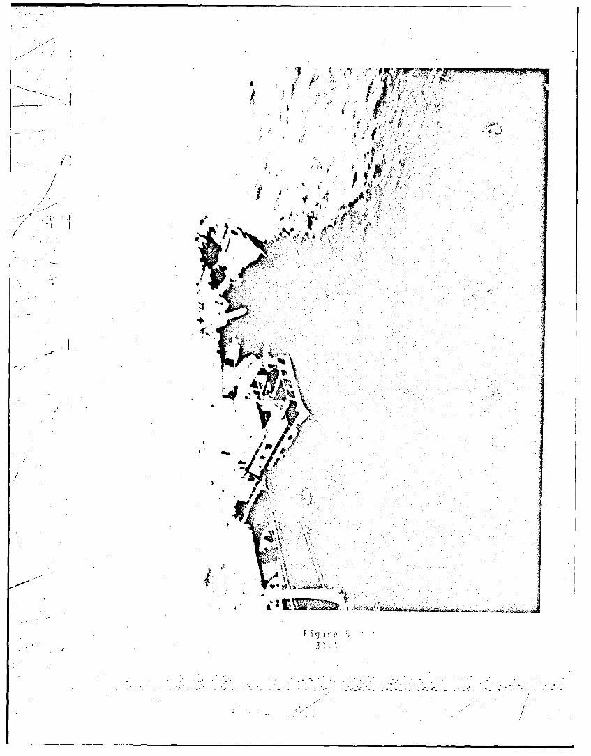
I ¶t it
'4�4 f
I >***/9/ ( A I,.
* ,,j�--------- 4 4.' 4w 4
/ ,-'-- I'. * U KA¼tr*V j S
Cr
V
9.
/ft
ta' 9/
I'
- 5/ -� tI
Figure ;/ .
* 1' '- /

71 Cf � ,� fry
4�
Ai
¶
4-
k
IN>
4
1�* IC I
1<II'
4 2 .re ¾43 r
-� �......-
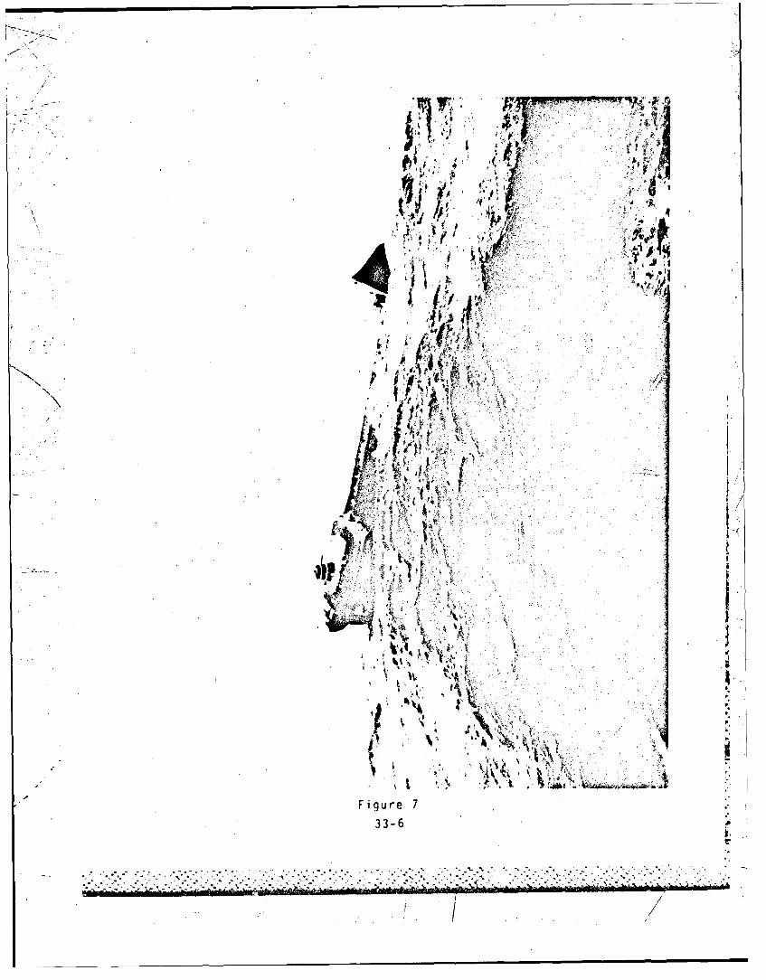
'Fis
qikh�. 411 tVP
4At,� Va IA
'4 k-A#uv
-.
+ s�'j�'p V :'
N f %� 3 ½* N
t �KIF i� s�f� a
r q'�4st�. I�At2 I(4 j�;*�i
KIt
Q
½ j��;:;� &
ANxi,7v&t 1 .r 9.
* �
3. 1 PI r 'N -st
A
Figure 733-6 a
e.
............................... 3 3. . . .
�............3 .
. .--.-.. 3..-.-..J.- - . 3 . - - -
1� / . /

S>¾,
I N1 r>•W ,...
i;- - ,. •
- tt'Figur 8
33-7
. . . . .. . . . . . , . . . ' ' . - . - . , , . -N-C ' ' . - " Z - ' " , . . ' . . . - . .W . .. . . . • . . . . . . ' ' ..
• i- -:.' 1 -- • ": " -1 " '-" " : ' °1 ": :." 1 "1 .' : .' .' 'K ,
/IC
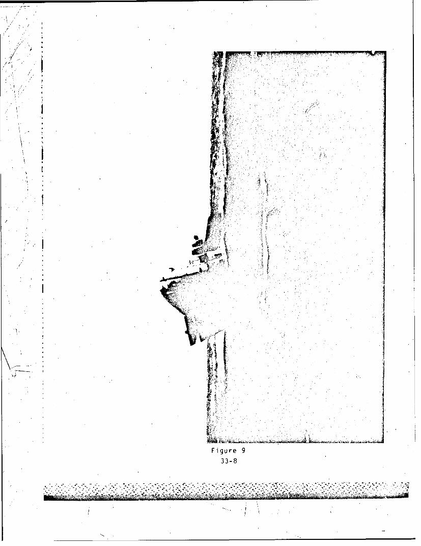
.4 t
' ii
t ii
id
JV
Ui.~{
Fiur
'*>•
t ;
t
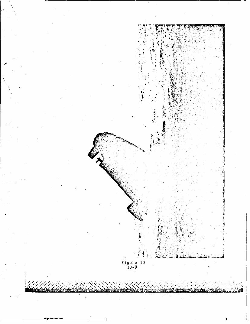
\4
44
r A•i. •• • ' •• • ,•./
• S•• • •
4.'i
Fiue1
33-9
'°o '... -,o% •, ',.-• •-'° ".•°• •'.•'• "o''."".• °" .• .r •'L• .' • •-".'°.• • •• "• •• •- °.' •" "• °.• , • '• " • " • • • •
4
• . f....A...t, !.

30
gb4A~4
Fi u e I II
33-10

-"o
-- °
*1
]• •• • +-•!•;o!•,i, * 1.. .. • ,,
K >, ,- iii
. , •i.• •.• . .• t * '
•-
S. . ..I . •.. .. . . .. •• • i11,, • . ~
"' '"U,) - *'', - >. •• L . ., .. . *// , • • A .i • !
" U-''
i•I" ~.;•,] "1"-Figure 12
i•.-;" 3 3-1 1
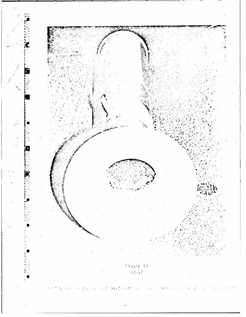
- Tr.vr r�r-'r'�"rswu�� '4rw ,w, � N �'-�r'
'4$
- '4, 1'¾
N:. ft- H 4 .4
r
-- �
r
4. * '4
'4,
t t
.7. 1 4.&Nr
* s''E' I t S
fI*t A,-? ,,- *4
S 4%.9 41' I'
4$.' ., r
K44
$
1�44.
U
,t'� 4.
r-4 '4.4
'4 -- �:.
".1
I.
A i Ku re 13
33-1?0
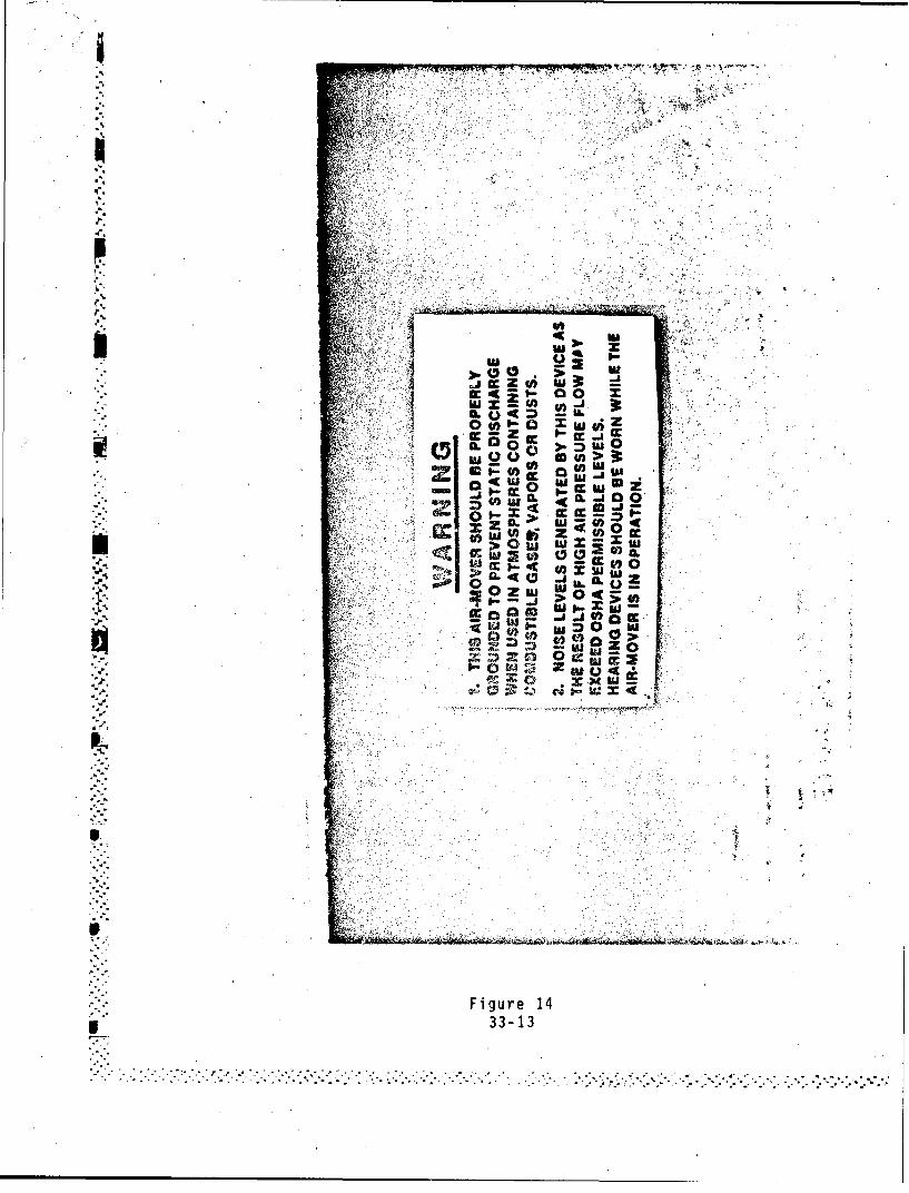
2 hw Z U)
a 4 a
CC ~ Z
ck 00 Z
Ix Us - to w
'-0 0
Uf -ow 10-IL wE~.i
C&, to W xcc j 40 a fc
la 0
to~
7DS
1- 0 RA *
* °CONCLUSIONS
1- That the proximate cause of this casualty was the intro-duction of steam through a venturi type air mover with attachedplastic sleeve into the #3 center cargo tank which was not ren-dered free of flammable vapors. The ignition of hydrocarbonvapors by a static charge from the ungrounded air mover, in theblower mode, introducing steam into the #3 center cargo tank
. "caused the explosion.
2. That the evidence indicates the AMERICAN EAGLE had some minormaintenance problems with regard to the cargo system while dis-
I •charging cargo at the Roosevelt Roads Naval Station, Puerto Rico.• The major extent of the problems centered around the quality ofthe product delivered and were not safety oriented. The only
safety related item would have been the product in the cargopumproom bilges as a result of leaking cargo pump seals. Cargo"pump seals are a relatively frequent maintenance item on tankvessels. Pumproom bilges are usually pumped or stripped period-ically into a slop tank or cargo tank containing a similiarproduct.
3. That there is no evidence that the problems experienced bythe AMERiCAN EAGLE at the Roosevelt Roads Naval Station on 27-29December 1983 were related to or contributed to the explosion on26 February 19814.
14. That the discrepancies noted by a Coast Guard boardingofficer at Port Everglades, FL, on 19 February 1984 did not con-tribute to the casualty.
5. That the repairs made to deck steam lines by the ChiefEngineer and the Fiist Assistant Engineer on the morning of 26February 1984 were not related to and did not contribute to thecasualty.
6. That the Bosun and Chief Mate most likely went forward to theforedeck on the starboard side, after coffee, and were notobserved by the Master who was talking to the Pumpman on the portside.
7. That the #3 cargo tank, on the morning of 26 February 19814,was not gas free and contained an explosive mixture of gasolinevapors and oxygen (ambient air).
8. That hydrocarbon vapors remaining in cargo tank #3C providedthe source of fuel for the explosion.
9. That there is evidence that the gas freeing procedures 46
followed by the Chief Mate, which included the introduction of rsteam into non-gas free tanks, was improper and did not followacceptable procedures as outlined in the International SafetyGuide for Oil Tankers and Terminals (ISGOTT), a copy of which wasaboard the vessel.
34
.. ...i* * . . . . . .
10. That the air mover was placed in the 03 cargo tank and thesteam was turned on immediately after Able Bodied Seaman Pooleobserved the attached plastic sleeve being placed in the #3Butterworth opening.
11. That there is no evidence of personnel working in any cargotanks, of anyone doing hotwork or smoking or of other actionsthat may have been a source of ignition.
12. That there is some 4uestion as to whether all precautions' associated with the Lamb air mover ventilator were being observ-
ed. The warning label states that the device should be grounded;.however, testimony verified that the device was not properlygrounded.
13. That the air mover was not intentionally grounded when itwas placed in the #3 center cargo tank.
14. That the air mover may have been insulated from the ships"hull by the plastic sleeve, dirt, gasket material, or paint, whenit was placed in the #3 center cargo tank Butterworth opening.
#. ~'15. That a copy of the International Safety Guide for OilTankers and Termin&ls (ISGOTT), which represents good, wellproven international industry practice, was on board butobviously theship's personnel were not aware of or did not heed
* the specific warnings on the hazards of using steam in a non-gasfree atmosphere.
16. That the Chief Mate and Master should have been aware of the• . hazards associated with introducing steam into non-gas free tanks-' as stated in ISGOTT.
17. That the AMERICAN EAGLE did not have sufficient compressedair capacity available on 26 February 1984 to effectively operatean air mover.
.' 18. That the testimony of the radio operator, Fred Conklin,"indicating there were three separate explosions was discounted by
.. the Board. All other testimony received indicated there was onlyone explosion heard or felt. The number of explosions is notconsidered material to the casualty or this investigation.
19. That the emergency radio transmitter was operating properlyas indicated by a signal received in the radio room and heard bythe radio operator. The cause for the weak signal could not be
"- determined, however, it may have been due to improper operatingprocedures or damage to the receiver in the radio room as aresult of the explosion.
"20. That the cause of the malfunctioning flares could not be
, •determined. However, it is possible'that some of the flares usedwere outdated flares retained onboard for instructional purposes.It is also possible that the crewmembers were unaware of the
* 535' 7'- " ,.' . . .. . . . . " • • ,, . . . - , . . . .. .. - , . - • ,. • .- , . . . . ... . -. . . .. . .
I
.* safety pin installed on Proteus 2 flares manufactured after April1981. This is no longer a problem as these particular devicesare no longer manufactured.
"21. That the problems encountered with the flares did not con-"tribute to the casualty, as radio communications were estab-lished and maintained shortly thereafter.
22. That had the Master secured all cargo tank hatches, Butter-i worth plates, and watertight doors at the time he ordered all
valves to be shut, the vessel may not have sunk as rapidly,allowing more time for an orderly evacuation.
23. That had the Master lined up the four cargo pumps to cargotanks #5, #6 and/or #7 across, rapid dewatering of those tanksusing the cargo pumps may have prevented or reduced the rate of
- sinking allowing more time for an orderly evacuation of tha"vessel.
*.24. That the cxact cause of the failure of the #3 lifeboatdavits to lower the lifeboat to the water could not be determin-
Sed. However, the most probabla cause may have been the severetrim by the head of the AMERICAN EAGLE, in excess of 10 degrees,
- coupled with the extreme list to starboard causing the lifeboatfalls to come out of the sheaves at the davit head as the life-boat swung freely by the falls, causing the falls to bind at the
i head of the davit and thereby preventing the boat from lowering.
* 25. That the lifeboat and it's occupants suffered little harm ordamage from the free fall when the releasing gear was activated,was due to the unintentional timing of the sea to crest in 'iay ofthe lifeboat as it dropped.
26. That had the crew remained in the lifeboat the chances of"survival of those missing and presumed dead and of the two that"died after abandoning the AMERICAN EAGLE, would have been greatlyincreased.
27. That Steger R. Burney, Able Seaman, and Earsel Warren,Ordinary Seaman, abandoned the AMERICAN EAGLE with the othercrewmembers. After entering the water, they became sepoaatedfrom the main group of survivors and were not located by rescuecraft.
"*' 28. That Steger R. Burney, Able Seaman and Earsel Warren,Ordinary Seaman, are missing and presumed dead.
29. That Edward J. Mallon, Chief Mate, Jack R. Campbell, Bosun,and Roy D. Carter, Pumpman, were working on deck in the vicinityof #2 and #3 center cargo tanks at the time of the explosicn.
.'3
S~36
•. .. .,... .. . ..... ..- P .... *2 • . :,:. .: .. ...... . . . ;-. .- , : , .- :-:.:..... ..- . .:.-:,* -, .:
, *-* . . *i

30. That Edward J. Mallon, Chief Mate; Jack R. Campbell, Bosun;7 and Roy D. Carter, Pumpman, were killed almost instantly by the
)!- * explosion aboard the AMERICAN EAGLE at approximately 1045 on 26February 1984 while the vessel was in position 27-30N, 91-30W in( the Gulf of Mexico. And further that their bodies were lost at3t4s or went down with the ship when the AMERICAN EAGLE broke' upar, sank on 27 February 1984.
. 31. That weather conditions did not contribute to the Initialcasualty, however the rapid deterioration of weather and seaconditions contributed to the rapid breakup and sinking of the
AMERICAN EAGLE.
* 32. That had the Master evacuated non-essential personnel afterthe explosion, the loss of life and injury resulting from theevacuation may have been reduced.
33. That the average age of the crew was 56.3 years. This,however, was not a factor in the casualty.
*" 34. That there is evidence of negligence on the part of theMaster Francis, Powers, with regard to the following actions orinactions:
(1) failure to assess the extent of structural damage toS-the vessel after the ex;0losion
- (2) failure to secure the ship after the explosion (closehatches and Butterworth plates)
1 (3) failure to follow-up with the Chief Mate on USCG de-' ficiencies issued at Port Everglades, Florida on' 19 February
1984
(4) failure to sound the general alarm and organize a fireparty after the explosion
(5) failure to evaluate the vessels condition after theL, explosion and make plans for a more timely and orderly evacuation
(6) failure to hold a crew muster after the explosion andprior to abandonment
This matter has been forwarded to the Commander, Eighth CoastDistrict for further investigation under the suspension and
*. revocation proceedings.
35. That the voluntary efforts of the M/V MOBIL VALIANT, forserving as a radio relay, and the M/V FORT EDMONTON, for standingby in excess of twenty-four hours and serving as a radio relay,are commendable and recognized.
1 37
*. . **

36. That the commendable assistance and lifesaving efforts ofthe crews of the M/V LIBERATOR, M/V ENTERPRISE and N/V STARLIGHTwas heroic and accounted for the saving of most of the lives ofthose in the water. Recognition for their actions has beeninitiated by the Commander, Eighth Coast Guard District.
37. That Coast Guard assistance rendered was both timely andadequate, considering the Master's and owner representative'sassurance that no other Coast Guard assistance was necessary orrequired.
38. That the AMERICAN EAGLE sank in 300 fathoms of water inapproximate position Latitudr 2; degrees North, Longitude 90.45degrees West, and does not constitute a menace to navigation.
39. That prior to the casualty and to the exten• ascertainable,with the exception of the discrepancies noted in the PortEverglades, FL, Coast Guard boarding, the AMERICAN EAGLE was in
.' -< all respects seaworthy and in full compliance with the Rules andRegulations for Tank Vessels.
40. That there was no evidence that the casualty was caused byany object or influence outside the vessel, or that any sabotage,willful intent to destroy, or any other form of foul play wasinvolved.
41. That had the Chief Mate and Master been aware of and com-plied with the recommendations in the International Safety Guidefor Oil Tankers and Terminals (ISGOTT) this casualty may havebeen prevented.
142. That the American Foreign Steamship Corporation did not havea formal safety program.
43. That with the exception of the above, there is no evidenceof actionable misconduct, inattention to duty, negligence, orwillful violation of law or regulation on the part of licensed orcertificated personnel, nor evidence that failure of inspectedmaterial or equipment, nor evidence that any personnel of theU.S. Coast Guard, or any other government agency or other personcontributed to the casualty.
38
I RECOMMENDATIONS
1. 'It is recommended that the Coast Guard issue precautions onthe use of steam in tanks that are not gas free. Steam shouldnot be injected into non-gas free tanks. All personnel involvedin tank cleaning/gas freeing operations should be made aware ofthe hazards.
I 2. It is recommended that the Coast Guard publish a safetyadvisory to alert seamen who serve aboard tank vessels of the.need to ground cargo tank ventilating blowers. This isparticularly important with respect to portable venturi air moverventilators as used aboard the'AMERICAN EAGLE.
3. It is recommended that ISGOTT be endorsed by the Coast Guardand that a copy be required aboard all U.S. tank vessels andthose foreign tank vessels entering U.S. waters.
4. It is recommended that consideration be given to requiring* the inerting of cargo tanks containing flammable products such as* gasoline. Present regulations only require inerting of cargo- tanks containing crude oil on existing vessels of tonnages
I rimilar to the AMERICAN EAGLE.
" 5. It is recommended that the use of portable venturi air moverventilators, when operated in the blower mode, be prohibited inany spaces which are not gas free.
6. It is recommended that portable venturi air mover ventilatorsbe used in accordance with provided warning labels.
- 7. It is recommended that manufacturers of portable venturi airmover ventilators provide a practical and positive method ofgrounding these devices
39

"8.' It is recommended that this report be given wide dissemi-nation to the marine industry by means of the Marine SafetyCouncil Proceedings after final action by the Commandant and theNational Transportation Safety Board. This Marine Board believesthat by publicizing the factors which led to this casualty, manymariners will relate them to their own shipboard operations,perhaps recognizing potential hazardous situations in time totake necessary corrective action.
S9. It is recommended that this casualty investigation be closed.
A. E. TANOS, CAPTAIN, U. S. COAST GUARD* iChairman
• .Q Q J_ _* F• J. KERLIN, U. S. COAST GUARD. Member
D. W. KUT-Z, LSUTENANT, U. S. COAST GUARDMember and rder
40

/~h
I APPENDIX A
NSA data sheet 26-00-01, Lamb Air-Mover Ventilator
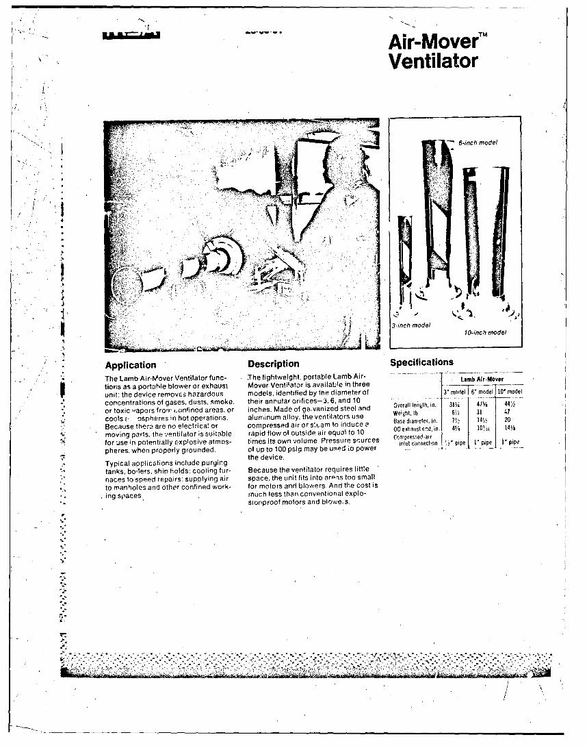
Air-MoverT
Ventilator
6-inch model
1 vl v
. . '!• ,•,'7y '{
3-inch model10-inch model
Application Description Specifications
The Lamb Air-Mover Ventilator func- The lightweight, portable Lamb Air- Lamblkir.Mover' tions as a portable blower or exhaust Mover Ventilator is availaile in three
unit: the device removes hazardous models, identified by the diameter of 3r model 6' model 10' model
S- concentrations of gases, dusts, smoke. their annular orifices-3, 6, and 10
or toxic vapors from ,onfined areas. or inches. Made of gavanized steel and Overall length, in. 31 475 44,
cools • ospheres in hot operations. alrfinum alloy, the ventilators use Weiamt, lb | 3 1 47
Because there are no electrica! or compressed air or s~,am to induce 0 BOse diameter, in. 74 1 14•¼, 20
moving parts. the ventilator is suitable rapid flow of outside air equal to 10 00 erhastendin. 45 10l 14//1
for use in potentially explosive atmos- times its own volume. Pressure srurces inlet conr ection 2" PIPe Vi piPe I I' pipepheres, when properly grounded. of up to 100 psig may be us.ed io power
the device,Typical applications include purgingtanks, boilers. ship holds: cooling fur- Because the ventilator requires little
naces to speed repairs: supplying air space. the unit fits into arpis too small
to manholes and other confined work- for motors and blowers, And the cost is
ing spaces, much less than conventional explo-sionproof motors and blowe, s.
-I2.
I. P - - - - - - .-
! ,/

No moving parts required. Compressed-Beair or steam lines can be quickly con- Outlet hornnected to a fitting on the bell of the"unit. As the'air or steam enters theannular orifice, decompression and
Sexoansion produce a powerful venturieffect which pulls in a large amount of Induced airthe air around the bell. The air is thenforced through the outlet horn at highvelocity.
Annular orifice
Compressed-air or steam connection
"Typical Performance Warning, Gage pressure Compressed air Induced a~r Discharge Nosaeelieeatdbrhi eieS.......Noise levels generated by this device,
e (prssue C ssem a dcf (sch )air as a result of high airflow, may exceed(s).... OSHA permissible levels. Hearing pro-
20 60 740 800 tective devices should Le worn !,henr40 105 900 1005 the Lamb Air-Mover Ventilator is in
Flow test 150 1060 1210 operation.3' model 80 195 1225 1420
100 240 1400 1640 Ordering Information
20 120 2550 2C70 Catalog numbers
40 260 3450 3710 32119 Lamb Air-Mover, 3' model
Flow test 60 390 4400 4790 32120 Lamb Air-Mover, 6" nrodel6' model 80 130 5300 5830 335-2 LambAir-Mover, 10- model
100 670 6950 7620
2' 31`0 3800 41304U 520 5M00 6326
Flow test 60 710 7700 8410l1model 80 910 9100 10200
100 1100 9700 10800
Note: Flew rates shown above are typical for compressed air. At a given manifold pressure,steam data should be similar. Contact MSA for complete details.
Note: Th s Data Sheet is a guide. contain- Mine Safety Appliances Compan•ing only a general description of the uses 600 Penn Center BRcr!jevardand performance capabilities of MSA Lamb Pittsburgh, Penns\,,vania 15235Air-Mover Ventilators Before use, refer toand strictly follow all instructions cautions, At your service 25 branch offices in the UnitedO Stat'";
MSA CANADA Downsview. Ontario lMetro Toronto) -ahia,and warnings on or with the product. For Montreal. Winnipeg. Saskatoon. Edmonton. Calgary, Vancouvermore complete information, contact MSA, representatives in principal cities of the world.600 Penn Center Blvd., Pittsburgh, Pa. Cable address -"MtM SAF" Pittsburgh15235.
Dita Sheet 26-00-01 Printed in U.S.A. 75S(L)
. R.e
aro-o tiann-2qcrdtte r ftfkona

APPENDIX B
Excerpts from second edition ofInternational Safety Guide for Tankers and Term~inals
(ISGOTT)
AM
International Safety Guide forOilTankers & Te1in als
Second Edition
International Chamber of ShippingOil Companies International Marine Forum
International Association of Ports and Harbors
V -x
., . . ' il- .=:: :: 'i
.1
First Published in 1978 byWitherby d Co. Ltd., 32/36 Aylesbury Street,
London, ECIR OET, England
Reprinted April 1979
Second Edition 1984
* © The Secretary-General, International Chamber of Shipping, Londonand
"Oil Companies International Marine Forum, Bermuda1978, 1979, 1984
ISBN 0 900886 88 9
While the advice given in this guide has been developed using the bestinformation currently available, it is intended purely as guidance. Noresponsibility is accepted by the Oil Companies' International Marine
"Forum, the International Chamber of Sihipping, InternationalAssociation of Ports and Harbors, or by any person, firm,
corporation or organisation who or which has been in any way"concerned with the compilation, publication or authorised
translation, supply o, sale of this guide, for the accuracy of any: info. mation or advice given herein or for any omission herefrom or
for any consequences whatsoeve resulting directly or indirectly fromcompliance with or adoption or guidance contained herein.
"Printed in England byWitherby & Co. Ltd., London, ECI
*][ II
Chapter 8
Tank Cleaning and Gas Freeing
This Chapter deals with the procedures for cleaning and gas freeing cargo tanks and other enclosed spaces after thedischarge of volatile petroleum or of non-volatile petroleum carried in a non-gas free tank, or when there is apossibility offlammable gas entering the tank or space. Safety precautions to be taken are set out, including thoserelated to crude oil washing of cargo tanks.
8.1 SUPERVISION AND PREPARATIONS
8.1.1 SupervisionA responsible officer must supervise all tank cleaning and gas freeing operations.
8.1.2 PreparationsBoth before and during tank cleaning and gas freeing operations, the responsible officer should be"satisfied that all the appropriate precautions set out in Chapters 2 and 6 are being observed. All personnelon board should be notified that tank cleaning or gas freeing is about to begin.
If craft are alongside the tanker, their personnel should also be notified and their com~pliance with all"appropriate safety measures should be checked.
Before starting to gas free or tank clean alongside a terminal, the following additional measures should
be taken:
The precautions in Chapter 4 should be observed as appropriate.
The appropriate personnel ashore should be consulted to ascertain that conditions on the jetty do not( present a hazard and to obtain agreement that operations can start.
98.1.3 Gas Freeing and Tank Cleaning Concurrently With Cargo Handling"As a general rule tank cleaning and gas freeing should not take place concurrently with cargo handling.If for any reason this is necessary, there should be close consultatien with, and agreement by, both theterminal representative and the port authority.
"Crude oil washing and cargo discharge may take place concurrently, but the terminal representativeshould be advised (see Section $.4).
"8. 1.4 Testing of Tank Cleaning HosesAll hoses should be tested for electrical continuity in a dry condition prior to use and in no case shouldthe resistance exceed 6 ohms per metre length.
8.1.5 Entry Into Cargo TanksNo one should enter any cargo tank unless permission to do so has been received from the responsibleofficer and all appropriate precautions have been taken, including the issue of an entry permit (see
- Chapter 10).
8.1.6 Gas Measuring EquipmentIn order to maintain a proper control of the tank atmosphere and to check the effectiveness ofgas freeing,a number of gas measuring instruments should be available on the ship.
-l .- 55
V

Depending upon the type of atmosphere being measured, at least two of each of the following portableinstruments should be available:
With a too lean tank atmosphere
- flammable gas indicator capable of measuring gas to the lower flammable limit (LFL) and withthe scale graduated as a percentage of this limit.
With an inerted tank atmosphere
- gas indicator capable of measuring percentage volume of hydrocarbon gas in an inertedatmosphere.
- oxygen analyser.
" With an over rich tank atmosphere
- gas indicator capable of measuring hydrocarbon gas concentrations above 13% volume in air:
In order to be able to check the effectiveness of gas freeing for tank entry the following instruments shouldbe provided:
- a flammable gas indicator capable of measuring gas to the lower flammable limit (LFL) and"with the scale graduated as a percentage of this limit.
- an oxygen aniilyser.
an instrument capable of measuring concentrations in the human toxicity range of toxic g".Land calibrated in parts per mi'lion.
"The instruments to be used for gas measurement should be calibrated and tested in accordance with themanufacturer's instructions before starting to tank clean or gas free.
S Tank atmosphere sampling lines should be in all respects suitable for and impervious to the gases present,
and should be resistant to the effects of hot wash water.
8.2 CARGO TANK WASHING AND CLEANING
8.2.1 Tank Washing AtmospheresTank washing car be carried out in any of the following atmospheres:
"Inerted - An atmosphere made incavable of burning by the introduction of inert gas and theresultant reduction of the overall oxygen content. For the purposes of this guide theoxygen content of the tank atmosphere should not exceed 8% by volume.
Too lean - An atmosphere made incapable of burning by the deliberate reduction of theShydrocarbon content to below the lower flammable limit (LFL).
"Uncontrolled - An atmosphere which is not controlled and which can thus be above, below, or"within the flammable range.
Over rich -- An atmosphere made incapable of burning by deliberately maintaining thehydrocarbon content of the tank over the upper flammable limit (UFL). A
Shydrocarbon content of at least 15% by volume should be attained before starting"to wash and maintained throughout washing.
82.2 Washing in an Inert AtmosphereThe requirements for the maintenance of an inert atmosphere and precautions to be observed duringwashing are set out in Section 9.6.8.
*= 8.2.3 WashIng In a Too Lean Atmosphere
The following precautions must be observed:
(a) Before washing, the tank bottom should be flushed with water and stripped. The piping system,
56
r.--
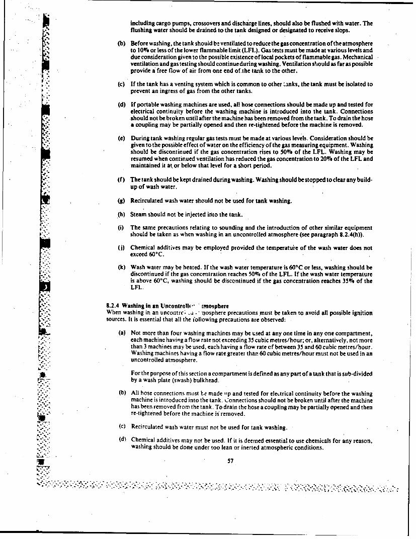
including cargo pumps, crossovers and discharge lines, should also be flushed with water. Theflushing water should be drained to the tank designed or designated to receive slops.
(b) Before washing, the tank should b2 ventilated to reducethe gas concentration of the atmosphereto 10% or less of the lower flammable limit (LFL). Gas tests must be made at various levels anddue consideration given to the possible existence of local pockets of flammable gas. Mechanicalventilation and gas testing should continue during washing. Ventilation should as far as possibleprovide a free flow of air from one end of the tank to the other.
(c) If the tank has a venting system which is common to other 'uks, the tank must be isolated toprevent an ingress of gas from the other tanks.
(d) If portable washing machines are used, all hose connections should be made up and tested forelectrical continuity before the washing machine is introduced into the tank. Connectionsshould not be broken until after the machine has been removed from the tank. To drain the hose"a coupling may be partially opened and then re-tightened before the machine is removed.
"(e) During tank washing regular gas tests must be made at various levels. Consideration should begiven to the possible effect of water on the efficiency of the gas measuring equipment. Washingshould be discontinued if the gas concentration rises to 50% of the LFL. Washing may beresumed when continued ventilation has reduced the gas concentration to 200 of the LFL and"maintained it at or below that level for a short period.
S."(f) The tank should be kept drained during washing. Washing should be stopped to clear any build-"up of wash water.
(g) Recirculated wash water should not be used for tank washing.
.(h) Steam should not be injected into the tank.
(i) The same precautions relating to sounding and the introduction of other similar equipmentshould be taken as when washing in an uncontrolled atmosphere (see paragraph 8.2.4(h)).
(j) Chemical additives may be employed provided the temperatuire of the wash water does not"exceed 60°C.
"(k) Wash water may be heated. If the wash water temperature is 600 C or less, washing should be"discontinued if the gas concentration reaches 50074 of the LFL. If the wash water temperatureis above 60°C, washing should be discontinued if the gas concentration reaches 35%, of theLFL.
8.2.4 Washing In an Uncontrolli,' rnosphere
When washing in an uncontrc; •. .j -nosphere precautions must be taken to avoid all possible ignitionsources. It is essential that all the following precautions are observed:
(a) Not more than four washing machines may be used at any one time in any one compartment,each machine having a flow rate not exceeding 35 cubic metres/hour; or, alternatively, not morethan 3 machines may be used, each having a flow rate cf between 35 and 60 cubic metres/hour.Washing machines having a flow rate greater thar 60 cubic metres/hour must not be used in anuncontrolled atmosphere.
For the purpose of this section a compartment is defined as any part of a tank that is sub-dividedby a wash plate (swash) bulkhead.
(b) All hose connections must to made ,,p and tested for electrical continuity before the washingmachine is introduced into the tank. Connections should not be broken until after the machinehas been removed from the tank. To drain the hose a coupling may be partially opened and then
,''. ~re-tightened before the machine is removed.
(c) Recirculated wash water must not be used for tank washing.
(d) Chemical additives may not be used. If it is deemed essential to use chemicals for any reason,"- -" .. washing should be done under too lean or inerted atmospheric conditions.
U57;
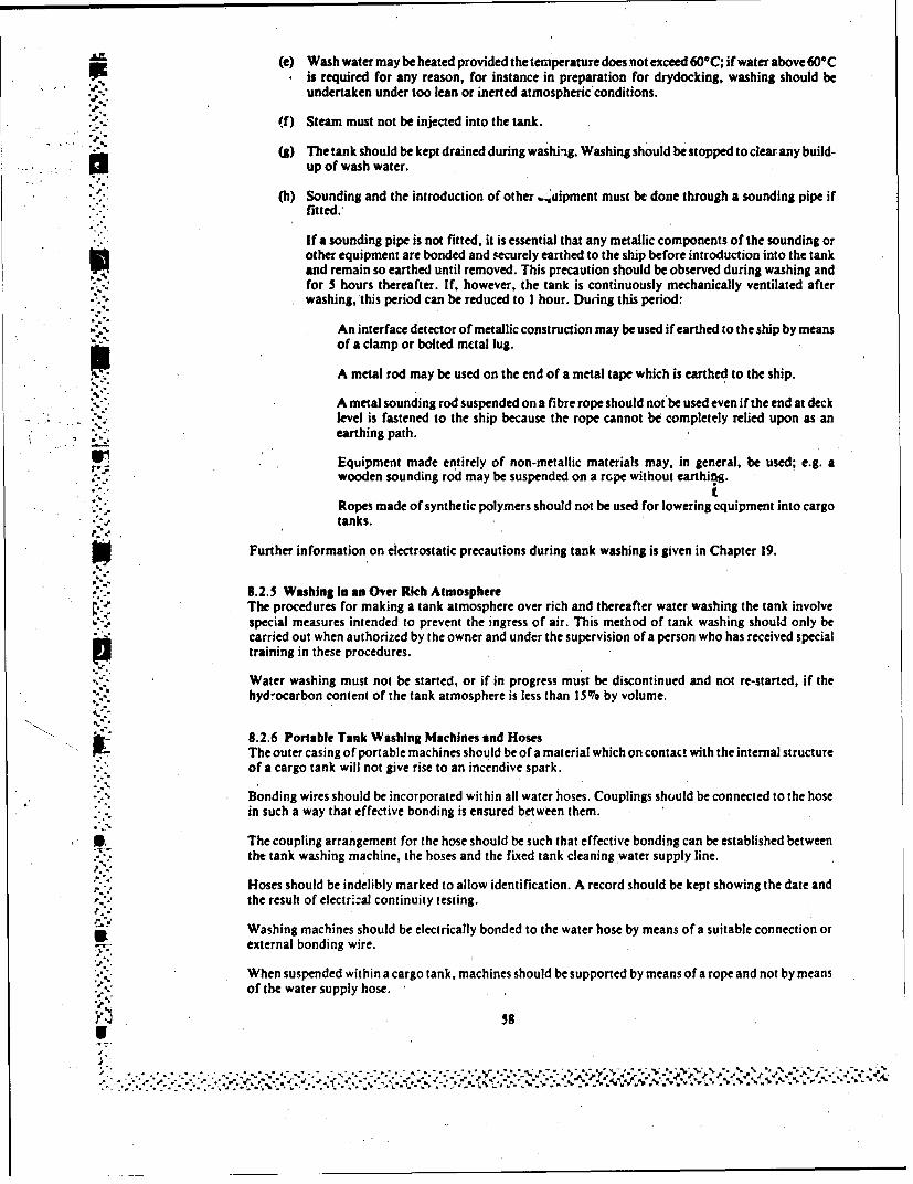
AZr, (e) Wash water may be heated provided the temperature does not exceed 60OC; if water above 600CSis required for any reason, for instance in preparation for drydocking, washing should be
undertaken under too lean or inerted atmospheric conditions.
"(f) Steam must not be injected into the tank.
- (g) The tank should be kept drained during washing. Washing should be stopped to clear any build-up of wash water.
(h) Sounding and the introduction of other ,..auipment must be done through a sounding pipe ifi'::fitted.,
If a sounding pipe is not fitted, it is essential that any metallic components of the sounding orother equipment are bonded and securely earthed to the ship before introduction into the tankand remain so earthed until removed. This precaution should be observed during washing andfor 5 hours thereafter. If, however, the tank is continuously mechanically ventilated afterwashing, this period can be reduced to I hour. During this period:
An interface detector of metallic construction may be used if earthed to the ship by meansof a clamp or bolted metal lug.
A metal rod may be used on the end of a metal tape which is earthed to the ship.
A metal sounding rod suspended on a fibre rope should not be used even if the end at decklevel is fastened to the ship because the rope cannot be completely relied upon as anearthing path.
SEquipment made entirely of non-metallic materials may, in general, be used; e.g. awooden sounding rod may be suspended on a rope without earthiag.
Ropes made of synthetic polymers should not be used for lowering equipment into cargotanks.
Further information on electrostatic precautions during tank washing is given in Chapter 19.
8.2.5 Washing In an Over Rich AtmosphereThe procedures for making a tank atmosphere over rich and thereafter water washing the tank involvespecial measures intended to prevent the ingress of air. This method of tank washing should only becarried out when authorized by the owner and under the supervision of a person who has received specialtraining in these procedures.
Water washing must not be started, or if in progress must be discontinued and not re-started, if thehydrocarbon content of the tank atmosphere is less than 15%0 by volume.
S 8.2.6 Portable Tank Washing Machines and Hoses
The outer casing of portable machines should be of a material which on contact with the internal structureof a cargo tank will not give rise to an incendive spark.
Bonding wires should be incorporated within all water hoses. Couplings should be connected to the hosein such a way that effective bonding is ensured between them.
3, The coupling arrangement for the hose should be such that effective bonding can be established between- .•, the tank washing machine, the hoses and the fixed tank cleaning water supply line.
Hoses should be indelibly marked to allow identification. A record should be kept showing the date andthe result of electr::al continuity testing.
Washing machines should be electrically bonded to the water hose by means of a suitable connection orS: external bonding wire.
When suspended within a cargo tank, machines should be supported by means of a rope and not by meansof the water supply hose.
58S
- - - - - -- .
8.2.7 Free FallIt is essential to avoid the free fall of water or slops in the receiving tank. The liquid level should always
4,. be such that the discharge inlets in the slop tank are covered to a depth of at least one metre to avoidsplashing. This is not necessary when the slop and cargo tanks are fully inerted.
8.2.8 Spraying of WaterThe spraying of water into a tank containing a substantial quantity of static accumulator oil could re.;ultin the generation of static electricity at the liquid surface, either by agitation or by water settling. Tankswhich contain a static accumulator oil should always be pumped out before they are washed with waterunless the tank is kept in an inert condition (see Section 7.4.2 and 7.4.4).
8.2.9 Steaming of TanksBecause of the hazard of static electricity, steaming may only be carried out in tanks which have beenwater washed and gas freed.The concentration of flammable gas should not exceed 10% of the LFL prior to steaming.
8.2.10 Leaded GasolineWhereas shore tanks may contain leaded gasoline for long periods and therefore present a hazard fromtetraethyl lead (TEL) and tetramethyl lead (TML), ships' tanks normally alternate between differentproducts and ballast and thus present very little risk. Ships employed in the regular carriage of leadedgasoline should flush the bottom of the tanks after every cargo discharge unless the tank is to be ballasted.
"Entry into ships' tanks used regularly for the carriage of leaded gasoline should be limited.
8.2.11 Removal of Sludge, Scale and SedimentBefore the removal by hand of sludge, scale and sediment the tank atmosphere must be safe for entry andan entry permit issued. The precautions described in Section 10.5.5 should be maintained throughout theperiod of work.
* ',, Equipment to be used for further tank cleaning operations, such as the removal of solid residues orproducts, in tanks which have been gas freed should be so designed and constructed, and the construction* materials so chosen, that no risk of ignition is introduced.
8.3 GAS FREEING
8.3.1 GeneralIt is generally recognised that tank cleaning and gas freeing is the most hazardous period of tanker
"operations. This is true whether washing for clean ballast, gas freeing for entry, or gas freeing for hotwork. The additional risk from the toxic effect of petroleum gas during this period cannot be over-emphasised and must be impressed on all concerned. It is therefore essential that the greatest possible care
~. -, is exercised in all operations connected with tank cleaning and gas freeing.
8.3.2 General Procedures"The following recommendations apply to cargo tank gas freeing generally. Additional considerationswhich apply when the tank has been inerted are given in Chapter 9.
(a) The covers of all tank openings should be kept closed until actual ventilation of the individual
tank is about to commence.
(b) Portable fans or blowers should only be used if they ai. hydraulically, pneumatically or steamdriven. Their construcion materials should be such that no hazard of incendiary sparking arises
* if, for any reason, the impeller touches the inside of the casing.
The capacity and penetration of portable fans should be such that the entire atmosphere of thetank on which the fan is employed can be made non-flammable in the shortest possible time.
(c) The venting of flammable gas during gas freeing should be by the vessel's appioved method,and where gas freting involves the e cape of gas at deck level or through tank hatch openingsthe degree of ventilation and number of openings should be controlled to produce an exit"velocity sufficient to carry the gas clear of the deck (see Section 6.8.2).
(d) Intakes of central air conditioning or mechanical ventilating systems should be adjusted toprevent the entry of petroleum gas, if possible by recirculation of air within the enclosed spaces.
- S 59
"". ..o. .. ,.'.- '. .. ,,..,. - ,., - . .- . ? .. • ,.-...,-..-:.4-...-, .........d. ... . .. .
5 ~If at anY time it is suspected that gas is being drawn into the accommodation, central airconditioning and mechanical ventilating systems should be stopped and the intakes covered or
closed.
Window type air conditioning units which are not certified as safe for use in the presence offlammable gas or which draw in air from outside the superstructure must be electricallydisconnected and any external vents or intakes closed.
(e) Where cargo tanks are gas freed by means of one of more permanently installed blowers, allconnections between the cargo tank system and the blowers should be blanked except when the
* blowers are in use.
Before *utting such a system into service, the cargo piping system, including crossovers anddischarge lines, should be flushed through with sea water and the tanks stripped. Valves on thesystem, other than those required for ventilation, should be closed and secured.
(f) Tank openings within enclosed or partially enclosed spaces should not be opened until the tankhas been sufficiently ventilated by means of openings in the tank which are outside these spaces.When the gas level within the tank has fallen to 25% of the LFL or less, openings into enclosedor partially enclosed spaces may~be opened to complete the ventilation. Such enclosed orpartially enclosed spaces should also be tested for gas during this subsequent ventilation.
*(g) If the tanks are connected by a common veiting system, each tank should be isolated to preventthe transfer of gas to or from other tanks.
(h) Portable fans, where used, should be placed in such positions and the ventilation openings soarranged that all parts of the tank being ventilated are equally and effectively gas freed.Ventilation outlets should generally be as remote as possible from the fans.
(i) Portable fans, where used, should be so con~nected to the deck that an effective electrical bondexists between the fan and the deck.
(j) Fixed gas freeing equipment may be used to gas free more than one tank simultaneously butI must not be used for this purpose if the system is being used to ventilate another tank in which
washing is in progress.
(k) On the apparent completion of gas freeing any tank, a period of about 10 minutes should elapsebefore taking final gas measurements. This allows relatively stable conditions to develop withinthe tank space. Tests should be made at several levels and, where the tank is sub-divided by awash bulkhead, in each compartment of the tank. In large compartments such tests should be
mdc at widely separate positions.If satisfactory gas readings are not obtained ventilation must be resumed.
()On completion of gas freeing all openings except the tank hatch should be closed.
S(in) On completion of all Cas freeing and tank washing the gas venting system should be carefullychecked, particular attention being paid to the efficient working of the pressure/vacuum valvesand any high velocity vent valves. If the valves or vent risers are fitted with devices designed toprevent the passage of flame these should also be checked and cleaned.
Gas vent riser drains should be cleared of water, rust and sediment, and any steam smotheringconnections tested and proved satisfactory.
8.3.3 Gas Free for the Reception of CargoA tank which is required to be gas free for receiving cargo should be ventilated until tests confirm that thehydrocarbon gas concentration throughout that tank does not exceed 40% of the LFL.
j 8.3.4 Gas Free for Entry and Cold Work Without Breathing ApparatusIn order to be gas free for entry without brer 'hing apparatus a tank or space must be ventilated until testsconfirm that the hydrocarbon gas concentration throughout the compartment is not more than 107 of theLFL and the additional tests have been made to check for oxygen content, the presence of hydrogensulphide. benzene and other toxic gases as appropriate (see Section 10.2).
60
8. 3.5, Gas Free in Preparation for Hot WorkIn addition to meeting the requirements of Section 8.3.4, the requirements of Section 10.5.7 must also becomplied with.
8.4 CRUDE OIL WASHING
8.4.1 GeneralI ~A crude oil tanker fitted with an inert gas system and fixed washinag equipment in its cargo tanks can usecrude oil from the cargo as the washing mredium. This operation may take place either in port or at seabetween discharge ports. It is mosi frequently carried out while the tanker is discharging cargo andpermits the removal of oil fractions adhering to or deposited on tank surfaces.'These deposits, whichwould normally remain on board after discharge, are then discharged with the cargo.
* As a consequence, the need to water 'wash the discharged tanks during the ballast voyage for the removalof residues is much reduced and, in some cases, entirely eliminated.
Water rinsing will be necessary if the tank is to be used for clean ballast.
Reference should be made to the IMO publication 'Crude Oil Washing ýSystems" and the vessel'sapproved Operations and Equipment Manual for further detailed guidance on the procedures involved.
8.4.2 Advance NoticeWhen it is required to carry out crude oil washing during cargo discharge the master should inform thecompetent authority and the terminal (or vessel when ship to ship transfer is involved) at least 24 hOVT'Sin advance, or in such time as is required. Crude oil washing should only proceed when their approval is
8.4.3 Tank Washing MachinesOnly fixed tank washing machines may be used for crude oil washing.
8.4.4 Control of Tank AtmosphereThe oxygen content of the tank must not, exceed 8076 by volume as described in Section 9.6.8.
*8.4.5 Precautions Against Leakage from the Washing SystemBefore arriving in a port where it is intended to crude oil wash, the tank washing system should be pressuretested to normal working 'pressure and examined for leaks.
All machines which are to be used st.ould be operated briefly to check for leaks beyc nd the shut-off va~ve.Any leaks round should be made good.
During crude oil washing, thc system mu!t be kept under constant observation so that any leak can bedetected immediately and action taken to deal with it.
8.4.6 Avoidance of Oil/Water MixturesMixtures of crude oil and water can proý':"e an electrically charged mist during washing much in excessof that produced by "dry" crude oil. The use of "dry" crude oil is therefore important, and beforeL washing begins any tank which is to be used as a source of crude oil washing fluid should be partlydischarged to remove any water which has settled out during the voyage. The discharge ot a layer at leastone metre in depth is necessary for this pu'pose.
For the same reason, if the' siop tank is to be used as a source ot oil for washing. it, should first becompletely discharged ashore and refilled with "dry" crude oil.
8 .4.7 Exclusion of Cargo Cil from ;he Engine RoomIf any part of the tank washing system extends into the engine room it must be blanked-off to preventcargo oil fiom entering the engine-room.
If the tank wash water heater is fitted outside the engine-room, it must be blanked-off during crude oilwashing to prevent oil from flowing through it.
8.4. 8 Control of Vapour EmissionsDuring crude oil washing hydrocarbon gas is generated within the cargo tanks beyond normally existinglevels. Subsequent ballasting of such cargo tanks could lead to considerable hydrocarbon gas beingexpelled to the atmosphere. Some port authorities prohibit such discharges.
61
is, unnoi jI lCU our ways:
-, I(a) 'By the use of permanent ballast tanks of sufficient capacity to provide the minimum departuredraught.
(b) By containing gas in empty cargo tanks by simultaneous ballasting and cargo discharge where* the ullage spaces of the tanks being ballasted are directly connected to those of the tanks being
discharged.
(c) By the gas compression method which requires that, on completion of the discharge, the tankpressure is at a minimum and all cargo tanks are made common via the inert gas line. Whileballasting, the gases rrom the ballasted cargo tanks are transferred through the inert gas linesinto the whole available cargo tank space and, with all vent valves, ullage ports, etc. closed, thegases are compressed within the vessel up to a safe margin below P/V valve and breaker settings.The P/V valves and breaker must be in good operational condition. All non-return devices must
be closed to prevent the back flow of inert. gas into the inc -t gas plant.
-, -. (d) By a suitable combination of any of these methods.
* Generally, the uillage spaces of all cargo tanks are connected by the inert gas main line. If the ballastingof dirty tanks can be commenced while discharge ,vontinues from other tanks, judicious adjustments ofI ballast and discharge rates can prevent the gas pressure rising sufficiently to cause a discharge toatmosphere. Where the ballast rate exceeds the discharge rate it may be necessary to reduce or eventemporarily stop the flow of inert gas to the tank system.
* 8.4.9 SupervisionThe person in charge of crude oil washing operations must be suitably qualified in accordance with therequirements laid down by the flag administration of the vessel and any port regulations in force locally.
* 8.4. 10 Cautionary NoticeA notice should be displayed in the cargo and engine control rooms, on the bridge and on the notice boardsof ships which carry out crude oil washing. The following text is suggested:
THE TANK WASHING LINES ON THIS SHIP'MAY CONTAIN CRUDE OIL. VALVES ONTHESE LINES MUST NOT BE OPENED BY UNAUTHORISED PERSONNEL.
8.5 SPECIAL TANK CLEANING PROCEDURES
After the carriage of certain products, tanks can only be adequately cleaned by steaming, or by theaddition of certain tank cleaning chemicals or additives to the wash water.
Steaming may only be carried out in tanks which have been either inerted or water washed and g~s freed.The concentration of flammable gas should not exceed 1007 of the LFL prior to steaming. Precautionsshould be taken to avoid the build-up of steam pressure within the tank.
If tank cleaning, chemicals are to be used, it is important to understand that certain products mayintroduce a toxicity hazard. P ersonnel should be made aware of the TLV (Threshold Limit Value) of theproduct. Personnel entering tanks should wear breathing apoaratus and appi-opriate protective clothing.All other tank entry precautions must be observed (see Section 10.4). Chemical absorption detectors areparticularly useful for detecting the presence of specific gases and vapours at TLV levels.
Tank cleaning chemicals capab~e of producing a flammable atmosphere should normally only be usedwhen the tank has been inerted. However, such products may be used to clean tank walls in a localised area
p (e.g. wiping down) in vessels not fitted with an inert gas system providcd the amount of tank cleaningchemical used is small and the personnel entering the tank observe all enclosed space entry requirements.
In addition to the above, any manufacturers' instructions or recommendations for the use of theseproducts should be observed.
Where these operations take place in port, additional requirements may be imposed by local authorities.
62
No
Ib
Chapter 19iStatic Electricity
1This Chapter deals with the generation of static electricity during the loading and discharging of cargo and during
.* tank cleaning. In addition the Chapter deals with ship to shore and ship to ship electric currents.
9 19.1 PRINCIPLES OF ELECTROSTATIC HAZARD
19.1.1 GeneralStatic electricitl presents fire and explosion hazards during the handling of petroleum, and tankeroperations are no exception. Certain operations can give rise to accumulations of electric charge whichmay be released suddenly in electrostatic discharges with sufficient energy to ignite flammable
a hydrocarbon gas/air mixtures; there is, of course, no risk of ignition unless a flammable mixture ispresent. There are three basic stages leading up to a potential static hazard: charge separation, chargeaccumulation and electrostatic discharge. All three of these stages are necessary for 4an electrostaticignition.
19.1.2 Charge separation* :. Whenever two dissimiliar materials come into contact charge separation occurs at the interface. The
interface may be between two solids, between a solid and a liquid or between two immiscible liquids. Atthe interface charge of one sign (say positive) moves from material A to material B so that matcriPs A andB become respectively negatively and positively charged. Whilst the materials, stay in contact andimmobile relative to one another, the charges are extremely close'together. The voltage difference betweenthe charges of opposite sign is then very small, and no hazard exists.
The charges can be widely separated by many processes, such as:
The flow of liquids (e.g. petroleum or mixtures of petroleum and water)through pipes or fine filters.
"The settling of a solid or an immiscible liquid through a liquid (e.g. rust or water through petroleum).
The ejection of particles or droplets from a nozzle (e.g. steaming operations).
The splashing or agitation of a liquid against a solid surface (e.g. water washing operations or theinitial stages of filling a tank with oil).
"The vigorous rubbing together and subsequent separation of certain synthetic polymers (e.g. thesliding of a polypropylene rope through PVC gloved hands).
When the charges are separated a large voltage difference develops between them. Also a voltage"distribution is set up throughout the neighbouring space and this is known as an -lectrostatic field. Asexamples, the charge on a charged petroleum liquid in a tank produces an electrostatic field throughoutthe tank both in the liquid and in the ullage space, and the charge on a water mist caused by tank washing"produces a field throughout the tank.
S* If an uncharged conductor is present in an electrostatic field it has approximately the same voltage as theregion it occupies. Furthermore the field causes a movement of charge within the conductor; charge of"one sign is attracted by the field to one end of the conductor and an equal charge of opposite sign is leftat the opposite end. Charges separated in this way are known as induced charges and as long as they are
•. kept separate by the presence of the field they are capable of contributing to an electrostatic discharge.
139
Aid vigil,
Charges which have been separated attempt to recombine and to neutralize each other. This process isknown as charge relaxation. If one, or both, of the separated materials carrying charge is a very poorelectrical conductor recombination is impeded and the material retains or accumulates the charge uponit. The period of time for which the charge is retained is characterized by the relaxation time of thematerial, which is related to its conductivity; the lower the conductivity the greater is the relaxation time.
If P material has a comparatively high conductivity the recombination of charges is very rapid ,nd can/ counteract the separation process, and consequently little or no static electricity accumulates c' thematerial. Such a highly conducting material can only retain or accumulate charge if it is insL.-ed bymeans of a poor conductor, and the rate of loss of charge is then dependent upon the relaxation time ofthis less conducting material.
The important factors governing relaxation are therefore the electrical conductivities of the separatedmaterials and of any additional materials which may be interposed between them after their sepa adLon.
19.1.4 Eleq'trostatic dischakrgesElectrical breakdown between any two points, giving rise to a discharge, is dependent upon the sti engthof the electrostatic field in the space between the points. This field strength, or voltage gradient, is givenapproximately by dividing the difference in voltage between the points by their distance apart. A fiek'strength of about 3,000 kilovolts per metre is sufficient to cause breakdown of air or petroleum gases.
The field strength near protrusions is greater than the overall field strength in the vicinity and dischargestherefore generally occu* ain protrusions. A discharge may occur between a protrusion and the space ip itsvicinity without reaching another object. These single electrode discharges are rarely, if -ver, incendivein the context of normal tanker operations.
The alternative is a discharge between twe electrodes adjacent to each other. EXampt es are:
Between sampling apparatus lowered into a tank and the surface of a chatged petroleum liquid.
Between an unearthed object floating on the surface of 'a charged liquid and the ad' :ent tankstructure.
Between unearthed equipment suspended in a tank and the adjacent tank structure.
Two-electrode discharges may be incendive if vario0s requirements are met. These include:
A discharge gap short enough to allow the discharge to take place with the voltage difference present,but not so she t that any resulting flame is quenched.
Sufficient electrical energy to supply the minimum amount of energy to initiate combustion.
The nearly instantaneous release of this energy into the discharge gap.
S* Whether the last requirement can be fulfilled depends to a large extent on the conductivity of theelectrodes. In order to consider this further it is necessary to classify solids and liquids intro three groups.
The first group is the conductors. In the case of solids these are the metals, and in the case of liquids thewhole range of aqueous solutions including sea water. The human body, consisting of about 60076 water,is effectively a liquid conductor. The important property of conductors is that not only are they incapableof holding a charge unless insulated, but also that if they are insulated and an opportunity for an electricaldischarge occurs all the charge available is almost instantaneously released into the discharge.
Discharges between two cmnductors very frequently occur as sparks, and are much more energetic andpotentially dangerous than those occur; ing between objects, one of which is not a conductor. In the lattercase discharges often take a more diffuse and much less dangerous torm, known as corona or brushdischarge, rather than a spark.
The second group is the non-conductors, which have such low conductivities that once thM'y have rece:veda charge they retair it for a very long period. Alternatively they can prevent the loss oi r fromconductors by actih.g as insulators, Charged non-conductors are of primary concern because they cantransfer charge to, or induce charge on, neighbouring insulated conductors which may then give rise tosparks. Very highly charged non-conductors may themselves contribute directly to incendive sparks.
140
- ,
piccSiemens/metre (pS/m) giving relaxation times greater tian 02 sec.ds; they are often known asstatic accumulators. In the case of petroleum, clean oils (distillates) frequently fall into this category. Anqntistatic additive is a substance which is deliberately added to a petroleum distillate to raise itsconductivity above 100 pS/m.
Tlh solid non-conductors are highly insulating materials such s oolypropylene. PVC, nylon and manytypes of rubber. They become more conductive as their surfaces are contaminate- I with dirt or moisture.
The third group is a range of liquids and solids with €onductivities intermed:t: - t* ween those of the firsttwo groups. The liquids have conductivities exceeding 100 pS/m and are often known as static noa-accumulators. Examples are black oils (containing residual materials) ard crude oils, which typically haveconductivities in the range 10,000-100,000 pS/m. Some chemical,, for example alcohols, are also staticnon-accumulators.
The solids in this int.-mediate category include such materials as wood, cork, sisal and naturallyoccurring organic substances generally. They owe their con tivity to thei- ready absorption of waterarid they become more conductive as their surfaces are contaminated by moisture and dirt. In some casesthorough cleaning and drying may lower their conductivities suffr;iently to bring them into the non-conductiv- range.
If materials in the intermediate conductivity group are not insulated from earth, their conductivities arenormally sufficiently high to prevent accumulation of an electrostatic charge. However, theirconductivities are normally low enough to inhibit production of energetic sparks.
The incendivity of a discharge from a material of inter.€,; i: conouctivi:y depends upon so many factorsin addition to conductivity that generalizations beyond the f -regoing are impossible, and it is necessaryto rely upon practical experience to indicate when it is acceptable to use themr..
Under normal conditions gas - :. highly insulating; this has important implications with respect to mistsand particulate suspensions ih air und other gases. Charged mists are formed during the ejection of wetsteam from a nozzle, while using tank washing machines and during crude oil washing. Although theliquid, for example water, may have a very high conductivity, the relaxation of the charge on the dropletsis hindered by the insulating properties of the surrounding gas. Fine particles present in inert flue gas orcreated during discharge of pressurized liquid carbon dioxide aie frequently charged. The gradui chargerelaxation which does occur is the result of the settlin of the particles or droplets and, if the field strengthis high, of corona discharge at protrusions which supplies a .-eutralizing charge of the sign opposite to thaton the suspension.
In summary, electrostatic discharges can occur ýs a result of accumulations of charge on:
Liquid or solid non-conductors, for example a static accumulator oil (such as kerosene) pumped intoa tank, or a polypropylene rope.
Electrically isolated liquid or solid conductors, for example mists, sprays or particulate suspensionsin air, or a metal rod hanging on the end of a synthetic fibre rope.
For materials with intermediate conductivities the risk of e ',:! .'rodic discharge is small, particularly ifcurrent practices are adhered to, and the chance of their be ý. nmdive is even smaller.
.2, 19.2 GENERAL PRECAUTIONS AGAINST ELECTROSTATIC HAZARDS
The most important countermeasure that must be taken to prevent an electrostatic hazard is to bond 0metal objects together; bonding -.limir.ates the risk of discharges L .tween metal objects, which can be very"energetic and dangerous. To avoid discharges from conductors to earth, it is normal practice to includebonding to earth (earthing or grounding). On ships, bonding to earth is effectively accomplished byconnecting metallic objects to the metal structure of the ship, which is -kturally earthed through the sea.
Some examples of objects which might be electrically insulated in hazardous situatiors and which musttherefore be bonded are:
Ship/shore hose couplings and flanges if more than one length of non-conducting hose or pipe isused in a string.
* , 141
/"

Portable tank cleaning machines.
Conducting manual ullaging and sampling equipment.
The float of a permanently fitted ullage device if it lacks an earthing path through the metal tape.
The most certain method of bonding and earthing is by means of a metallic connection between :heconductors. This method should be used whenever possible, although for electrostatic purposes anadequate bond can in principle be made using a material of intermediate conductivity.
Certain objects may be insulated fortuitously during tanker operations, ior example:
A metal object such as a can floating in a static accumulating liquid.
A loose metal object while it is falling in a tank during washing operations.
Every effort should be made to ensure that such objects are removed from the tank, since thereis evidentlyno question of deliberately bonding their. This necessitates careful inspection of tanks, particularly aftershipyard repairs.
19.3 ELECTROSTATIC HAZARDS WHEN HANDLING STATIC ACCUMULATOR OILS
19.3.1 Pumpinpl oil Into tanksPetroleum distillates often have electrical conductivities less than 100 picoSiemens/metre and thus fallinto the category of accumulators.
Since their conductivites are not normally known, all Jistillates mast be treated* as static accumulatorsunless they contain an antistatic additive (see Sectk,n 19.3.4). During and for somne time after entry into
all the tank a static accumulator oil may carry sufficient charge to constitute a hazard.
"The charge may arise through one or more of several different processes:
Flow of the oil through the pipeline system into the tank. Charge generation is enhanced if waterdroplets are suspended in the oil as it flows through the pipes.
Flow through a micropore filter of the kind used for aircraft jet fuels. These filters have the abilityto charge fuels to a very high level, probably because all the fuel is brought into intimate contact wi?,h"the filter surface, where cargo separation occurs.
Turbulence and splashing in the early stages of pumping the oil into an empty tank.
The settling of water droplets, rust or other particles entering the tank. with the oil or stirred up byit in the tank.
The generally accepted me'hod for controlling electrostatic generation in the initial stages of loading is torestrict the flow rate of the static accumulator oil into the tank until all splashing and surface turbulence
:J in the tank has ceased.
At the commencement of loading an empty tank the linear velocity in the branch line to each individualcargo tank should not exceed I met re/second (3 feet/second). The reasons for such a low rate are twofold:
It is at the beginning of filling a tank that there is the greatest likelihood of water being mixed withthe oil entering the tank; mixtures of oil and water constitutea most potent source'of static electricity.
A low loading rate minimizes the extert of turbul-nce and splashing as oil enters the tank; this helpsto reduce the generation of static electriciy and also reduces the dispersal of any water present, sothat it more quickly settles out to the bottom of the tank where it can lie relatively undisturbed whenthe loading iate is subsequently i.. 'reased.
During subsequent loading the limitations on flow rate imposed by present design of pipeline systems,coupled with precautions in the introduction of dipping, ullaging and sampling equipment (see Section19.5) and the avoidance of electrically isolated conductors, have proved sufficient to maintainoperational s;;fety. If, however, markedly different pipeline or pump ng systems were to b. introduced
J 142
enabling higher flow rates or velocities to be achieved then flow rate limitations might have to be imposedthroughout loading.
The limitation on the initial loading rate for static accumulator oils applies whenever a flammable gasmixture may be present. These situations are fully described in Section 7.4 and are summarized in Table"7-1.
It is not uncommon during loading to encounter water from such operations as water washing, ballastingor tine flushing and care should be taken to prevent excess water and unnecessary mixing. For example,cargo tanks and water flushed lines should be drained before loading and water should now be permittedto accumulate in tanks. Lines should not be displaced with water back into a tank containing a staticaccumulator oil.
Coarse filters are sometimes used in tanker operations. These generate an insignificant amount of chargeprovided that they are kept clean. However, if micropore filtration is used on the jetty sufficient time mustbe allowed for the charge to relax before the liquid reaches the tank. It is desirable for the liquid to spenda minimum of 30 seconds in the piping downstream of the filter.
"19.3.2 Fixed equipment in cargo tanksEquipment permanently mounted from the top of a tank, such as fixed washing machines or high levelalarms, may act as isolated probes. A metal probe remote from any other tank structure but near a highlycharged liquid surface will have a high voltage gradient at the probe tip. During the loading of staticaccumulator oils, this high voltage gradient may cause electrostatic --scharges to the approaching liquidsurface.
An isolated probe configuration can be avoided by installing the device adjacent to a wall or other tankstructure to reduce the voltage gradient at the probe tip. Alternatively a support can be added running"from the lower end to the tank structure so that the rising liquid meets an edge rather than th4. isolated tipof a probe. Another solution possible in some cases is to construct the probe-like device entirely of a non-'conductive material. These measures are not necessary if the vessel is limited to crude ar.d black oil service.
19.3.3 Air release In the bottom of tanksIf air or inert gas is blown into the bottom of a tank containing a static accumulator oil a strongelectrostatic field can be generated, especially in the presence of water or particulate matter. Accordinglyprecautions should be taken to minimize the amount of air or inert gas entering tanks containing staticaccumulator oils.
19.3.4 Antistatic additivesIf the oil contains an eff&tive - 'tistatic additive it is no longer a static accumulator. Although, strictly,this means that the precautions applicable to an accumulator can be relaxed, it is still advisable to adhereto them in practice unless it is certain that the conductivity is above 100 picoSiemens/metre.
19.4 OTHER SOURCES OF ELECTROSTATIC HAZARDS
19.4.1 Free fall in tanksLoading or ballasting overall delivers charged liquid to a tank in such a manner that it can break up intosmall droplets and splash into the tank. This may produce a charged mist as well as increasing thepetroleur' gas concentration in the tank. Restrictions upon loading or ballasting overall are given inSection 7.6.15.
"19.4.2 Water mistsThe spraying of water into tanks, for instance during water washing, gives rise to electrostatically chargedmist. This mist is uniformly spread throughout the tank being washed. The electrostatic levels vary widelyfrom tango to tank both in magnitude and in sign.
When washing is started in a dirty tank the charge in the mist is initially negative, reaches a mayimumnegative value, then goes back thro'igh zero and final:y rises towards a positive equilibrium value. It hasbeen found that, among the many variables affecting the level and polarity ofcharging, the characteristicsof the wash water and the degree of cleanlinesss of the tank have the most significant influence. Theelectrostatic charging characteristics of the water are altered by recirculation or by the addition of tankcleaning chemicals, either of which way cause vcry high electrostatic levels in the mist. The size andnumber of washing machines in a tank affect the rate of change of charge but they have little effect on thefinal equilibrium value.
143

The clarged mist droplets created in the tank during washing give i~se to an electrostatic field which ischaracterized by a distribution of potential (voltage) throughout the tank spac-. The walls and structureare at earth (zero) potential; the space potential increases with distance from these surfaces and is highestat points furthest from them. The field strength, or voltage gradient, in the space is greatest near the tankwalls and structure, more especially where there are protrusions into the tank. If the field strength is highenough electric breakdown occurs into the space, . ing rise to corona. Because protrusions causeconcentrations of field strength a corona occurs preferentially from such points. A corona injects a chargeof the opposite sign into the mist and is believed to be one of the main processes limiting the amount of"charge in the mist to an equilibrium value. The corona dischrges produced during tank washing are notstrong enough to ignite the hydrocarbon gas/air mixtures that may be present.
Under certain circumstances discharges with sufficient energy to ignite hydrocarbon gas/air mixtures canoccur from unearthed conducting objects already within, or i:atroduced into, a tank filled with chargedmist. Examples of such unearthed conductors are a metal sounding rod suspended on a non-conductingrope or a piece of metal falling through the tank space. Primarily by induction an unearthed conductorwithin a tank can acquire a high potential when it comes near an earthed object or structure, particularlyif the latter is in the form of a protrusion. The unearthed conductor may then discharge to earth givingrise to a spark capable of igniting a flammable hydocarbon gas/air mixture.
The processes by which unearthed conductors give rise to ignitions in a mist are fairly complex, and anumber o" conditions must be satisfied simultaneously before an ignition can occur. These conditionsinclude the size of the object, its trajectory, the electrostatic level in the tai~k and the geometrical"configuration where the discharge takes. place.
As well as solid unearthed conducting objects, an isolated slug of water produced by the washing processmay similarly act as a spark promoter and cause an ignition. Experiments have shown that high capacity,single nozzle fixed washing machines can produce water slugs which, owing to their size, trajectory andduration before breaking up, may satisfy the criteria for producing incendive cdscharges. On the otherhand there is no evidence of such water slugs being produced by portable typesgpf washing machine.
Following extensive experimental investigations and using the results of long-term experience, the tankerindustry has drawn up the tank washing guidelines set out in Chapter 8. These guidelines are aimed atpreventing excessive charge generation in mists and at controlling the introduction of unearthedconducting objects when there is charged mist in the tank. The guidelines apply to tanks of all sizes.
Charged mists very similar to those produced during tank washing occur from time to time in partlyballasted holds of OBOs. Due to the dcr ;qn of these ships there may be violent mist-generating impactsof the ballast against the sides of the hold* 'en the ship rolls in even a moderate sea. The impacts also giverise to free flying slugs of water in the tat . so that if the atmosphere of the tank is flammable all theelements for an ignition are present. The mct effective counter-measure is to have tanks either empty orfully pressed up so that the violent wave motion in the tank cannot take place.
19.4.3 SteamSteaming can proluce mist clouds which may be electrostatically charged. The effects and possiblehazards from such clouds are similar to th ý,e described for the mists created by water washing, but theintroduction of steam can cause very, much higher levels of charging than those produced by waterwashing. The time required to reach maximurn charge levels is also very much less. For these reasonssteam should not be injected into cargo tanks whe. - there is any risk of the presence of a flammableatmosphere.
19.4.4 Inen gasSmall particulate matter carried in inert gas can bN lectrosticafly charged. The charge separationoriginates in the combustion process and the charged r ,rticles are capable of being carried through the
.3 scrubber, fan and distribution pipes into the cargo tanks. The electrostatic charge carried by the inert gasis usually small but levels of charge have been observed well above those encountered with water mistsformed during washing. Because the tanks are normally in an inert conditinn, the possibility of anelectrostatic ignition has to be considered only if it is necessary to inert a tank which already contains a"flat.mable atmosphere or if a tank already inerted is likely to become flammable because the oxygencontent rises as a result of ingress of air. Precautions are then required during dipping, ullaging andsampling (see Section 19.5.5).
19.4.5 Discharge of carbon dioxideDuring the discharge of pressurized liquid carbon dioxide the rapid cooling which takes place can resultin the formation of particles of solid carbon dioxide which become charged on impact and contact with
"144

APPENDIX C
Report on Stability and Strength Calculationsof the AMEICAN EAGLE,
.1L
%-
p.
"US Department Commandant Washington, DC 20593
of Transportati United States Coast Guard Staff Symbol: G-MTH-5e (202) 426-2188
Coast GAuard It. "2/AMERICAN EL
, • o SEP 198,
From: Commandant"" T : Chairman, Marine Board of Investigation; SS. AMERICAN EA',t
SubJ: S.S. AMERICAN EAGLE, O.N. 278327 Marine Board of Investigation""lecdical Assistance
.ef : (a) Your letter 16732/S.S. AMERICAN EAGLE of 1 May 1984
",1. Ehclosure (1) is the final report of the technical analysis which you requestedby reference (a).
&.. ftm. i
kEhcl: (I) "S.S. AMERICAN EAGLE Casualty Investigation"Stability and Strength Calculations'Report dated 31 August 1984
U
- ' -. * - .

Ebiited States Coast Qjard* ~Office of Merchiant Marine Safety>4::Marine Technical and Hazardous material~s Division
8.S. AMIICAN EAGLE Casualty InvestigationStability and Strength Calculations
31 August 1984
\- I
"S.S. AMRICAN EAGLE Casualty InvestigationStability and Strength Calculations
7he Marine Board of Investigation requested ComnTandant (G+4TH-5) to performstability and strength analyses to assist in determining the cause of thesinking of the S.S. AMERICAN EAGLE, O.N. 278327 in the Gulf of Mexico on 26February 1984. The analyses requested consisted of the following tasks:
* 1. Calculate a loading condition just before the explosion based on theBoard's description of loading. Calculate and evaluate the intact
..stability of this loading condition.
,' 2. Calculate and evaluate the floating characteristics and damagestability of the stern section after the bow broke off using theprogressive flooding sequence prescribed the Board.
3. Perform a longitudinal strength analysis in still water. Determine theshear force between th,. bow and the stern section prior to the breakingaway of the bow.
4. Perform a bulkhead strength analysis to determine the hydrostaticpressure necessary to rupture a tank bulkhead.
This report contains a suTmmary of results, assuoptions and a brief descriptionof the analytical methods used.I
Ii
*o 1

1. InatStblt of the Ship Before the Ep~rlosion
7he Marine Board of Inm:estigation supplied a detcription of how the shipvas loaded just before the explosion. Using this description, ship's
* drawings and technical reports supplied by the Board, the loading,condition shown below was developed:
XT!7 DESCRIPTION WEIGHT L02IA FRCM4 c6
?(L.T.) (FT') FT (+) 1W!
Light Ship 9984 29.8 -30.5
Tank #lO Center 1747 17.0 -145.075% Full-Ballast
<' 1Tank #1 Port 972 24.6 +203.7100% Full-Ballast
Tank #2 Starboard 1138 23.6 +164.5100% FulI-Ballast
3Tank #6 Port 68 1.8 +15.031 of Ballast
Tank #6 Oenter 148 1.5 +15.0- 3' of Ballast
Tank #6 Starboard 68 1.8 +15.0* 3' of Ballast
20TAL 14,125 26.8-19
a24A
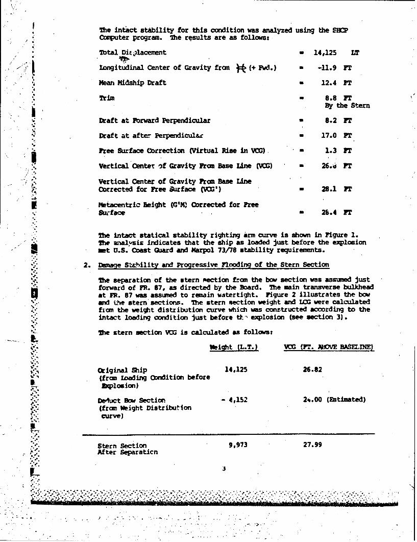
7 The intict stability for this condition was analyzed using the $MCmputer program. The results are as follows:.
71otal Dii ?lacement - 14,125 LT
•l longitudinal Center of Gravity from a (+ Fwd.) - -11.9 FT
Mean Midship Draft - 12.4 FT
Trim- 8.8 FTBy the Stern
* • -Draft at PForward Perpendicular 8.2 FT
Draft at after Perpendicul"r - 17.0 FT
Free Surface Correction (Virtual Rise in V) - 1.3 FT
.Vertical Center f Gravity From Base Line M) - 26.* ii T"Vertical Center of Gravity From Base Line
Corrected for Free Surface (N ') - 28.1 PT
Metacentric Beight (G'DV Corrected for FreeSuIrface - 26.4 PT
" " The intact statical stability righting arm curve is shown in Figure 1.2he analsic Indicates that the ship as loaded just before the explosionmet U.S. Coast Guard and Marpol 73/78 stability requirements.
* "2. Damage St'hility and Progressive Flooding of the Stern Section
"T•e separation of the stern mection from the bow section was assumed justforward of FR. 87, as directed by the Board. The main transverse bulkhead
* at FR. 87 was asswued to remain watertight. Figure 2 illustrates the bow-'= and 4he stern sections. The stern section weight and 103 were calculated
from the weight distribution curve which was constructed according to the"intact loading sondition just before tt.- explosion (see section 3).
Ihe &tern section VC is calculated as follows:
Weight BL.T.)AMME)
original Ship 14,125 26.82(from loading Condition before
, Explosion)
"DedIuct Dow Section - 4,152 2*.00 (Estimated)(from Weight Distributioncurve)
Stern Section 9,973 27.99, After Separaticn
3N
Sy . .] II -::.'.."- -
- , /* . . . . '4* .. . . -. **-*- +
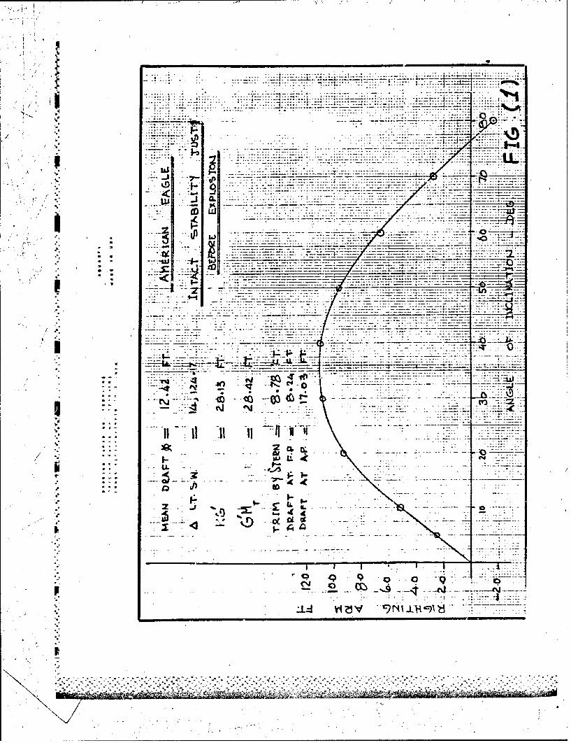
. . . . . . . . . . . . ... . . . . . . . . .. . . . . . ..... .-... ...
.. ......
., .... ...V- .........-
ii __ ______ __ 770
l ... ..
. .. . .. . ......
-7 - 7 4 -% . r -in-
7_ __
V- 7 - 7;j
~It .
z ~ ~ ' 494 f.~~-
61I *e.
Uo Vi 4V N I 1 97

4~,7
AFA
Lu 4_:
77 .. . . . . . . . . :.. . .
. ~ ~ ~ ~ ~ ~ ~ .d .. .... ... .... ... . q w
..... ....
~~7=7._ 7
*41.
JI
. . . . .. . .
. .. . .. . .
'7-77L 7:
-u*1
74-
777
Q
/4

-" Using the Sire computer program, the intact stability characteristics ofthe stern section alone were then calculated. The results are as follows:
Displacesment - 9973 LT
Longitudinal Center of Gravity fromof stern section (+ FWD) - - 17.0 FT
Man Draft Amidship - 13.2 FT
"Trim - 23.5 FT By the Stern
Draft at FR. 87 1.5 FT
"Draft at After Perpendicular - 24.9 FT
Free Surface Correction(Virtual Rise in VOG) - 1.7 FT
Vertical Center of Gravity fromBase Line (OG) - 28.0 PT
Vertical Center of Gravity fromBase LineCorrected for Free Surface (VNMI) - 29.7 FT
Metacentric Height (G'M) Corrected
* for Free Surface - 35.2 FT
T Treating the stern section as a separate vessel, a damage stabilityanalysis was performed using the progressive flooding sequence outlined bythe Board. Figures (3) through (16),graphically depict the results of"this analysis.
After separation from tne bow section, the stern section has a trim by thestern of 23.5 ft. As progressive flooding contirnes, the trim by the
.*. stern decreases gradually until the stern section beccmes nearly on aneven keel. Heel during this stage of flooding is 4 degrees. Theseconditions are shown in Figure 10.
Lip to this point, tanks No. 3 P/S/C, 4 P/S/C, 5 P/S/C and 6 S are flooded("igure 10). Additional flooding causes trim by the bow. Figure 11 shows
:-[ trim by the bow of 12.0 ft. Trim by the bow increases gradually asS..progressive flooding continues, until it reaches 81.1 ft. At this point,
"the deck house is submerged to the first level and the stern is out of theS* water. Starboard heel during this stage reaches a maximum value of 13
degrees (Figure 14).
Figure 15 shows tanks No. 3 P/S/C, 4 P/S/C, 5 P/S/C, 6 P/S/C, and 7 P/S/Cflooded. The transverse stability up to this point is indicated in therighting arm curves, Figures 3 through 15. Additional flooding beyond
* this point causes the stern section to become statically unstable (nopositive area under tie righting arm curve). In this condition, the sternsection will capsize in still water (See Figure .16).
U

p..p
. he following table indicates the drafts of the stern section at FR. 87 and at the alperpendicular and the starboard heel for the different stages of progressive floodinm
Condition No. and Total TTim (+) Draft at F,•. Draft at StarboarcDescription by Stern 87 on C.L. A.P. on Heel
(FT) (Fr) C.L. (FT) (Meg)
Intact Stern Section + 23.5 1.5 24.9 0
i (1) Tanks Flooded3 P/S/C + 22.1 2.4 24.4 0
(2) Tanks Flooded. as (1) above plus 4S + 21.4 2.8 24.2 1
E (3) Tanks Flooded-' as (2) above plus 4C + 17.9 4.9 22.7 1
* (4) Tanks Floodedas (3) above plus 4P + 16.1 6.0 22.1 0
(5) Tanks Floodedas (4) above plus 5S + 14.0 7.3 21.3 2
(6) Tans Floodedas (5) above plus 5C 4 9.0 10.4 19.4 2
(7) Tanks Flooded"- as (6) above plus 5P + 6.1 12.3 18.3 0
- (8) Tanks Floodedas (7) above plus 6S + 0.9 16.5 15.6 4
(9) Tanks Floodedas .8) above plus 6C - 12.0 24.0 12.0 6
- (10) Tanks Floodedas (9) above plus 6P - 19.6 29.1 9.5 0
L (11) Tanks F'lor',ed
"" as (10; -tt ve plus 7S -31.0 36.9 5.9 11
* (12) Tanks Flooded- as (11) above plus 7C -60.0 56.6 -3.4 13
(13) Tanks Flooded"as (12) above plus 7P -81.1 71.0 -10.2 0
(14) Tanks Floodedas (13) above plus 8S C A P S I Z E
F
,'• 77
0,.o
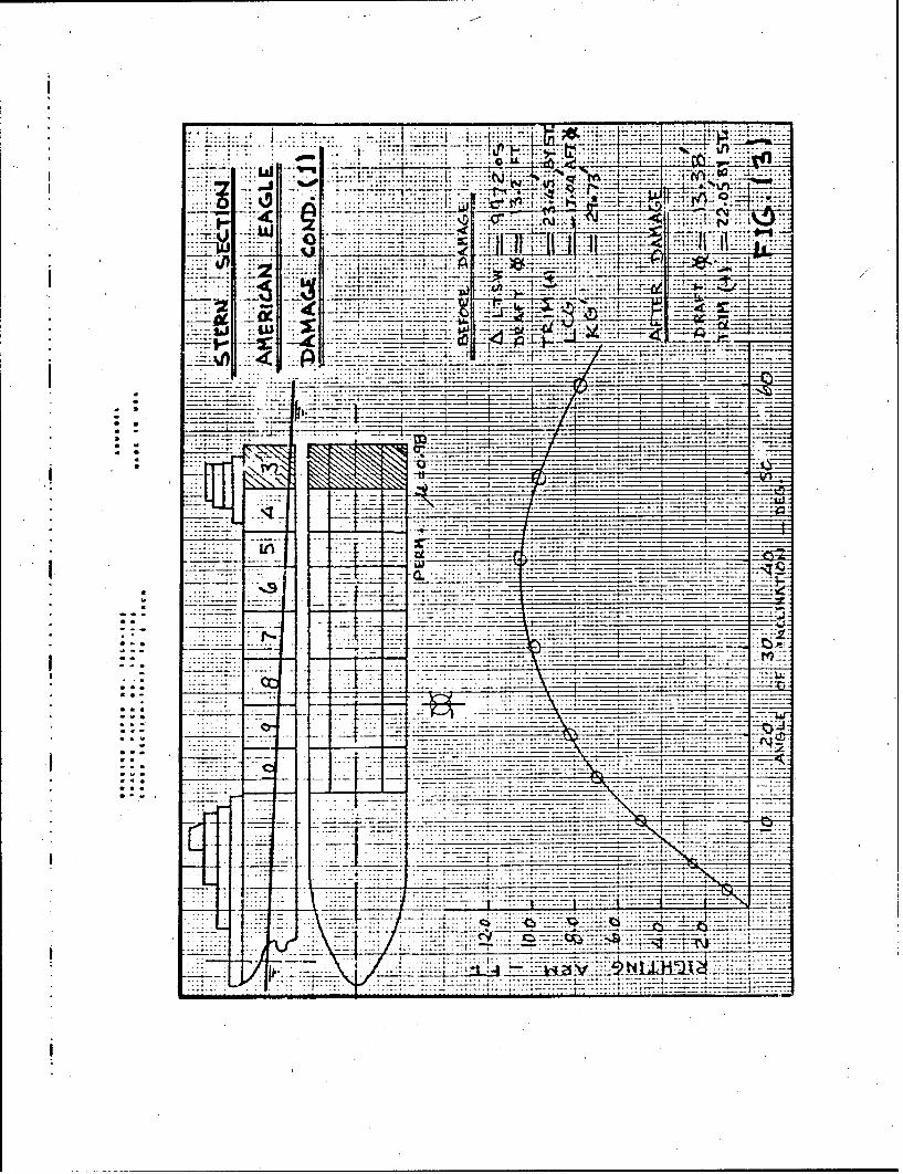
.7t7 I:li;l o 7 ...............-..;.
Ld. -v .. .. .. .....
.. .......... ....
__~~iiiiu
iS u __ F
V I-.--.------..- --. ------
C~~. . .. ........
ICY
-7-_777-77 7_______ __*-________________
* 32.
-- - -- -
t~~~ ____ 1_
________ ___________________________________________________-A______
........

I~~ -4;n I
a- ...-...- ---.-- --- - - ---.------------. ---.--------
TN

.. .. ........
. .. ... ..
.. . .. . ....... -.-- -
* ---..- ..-...........--
a.. .. .
774W
w: 7:
. .........
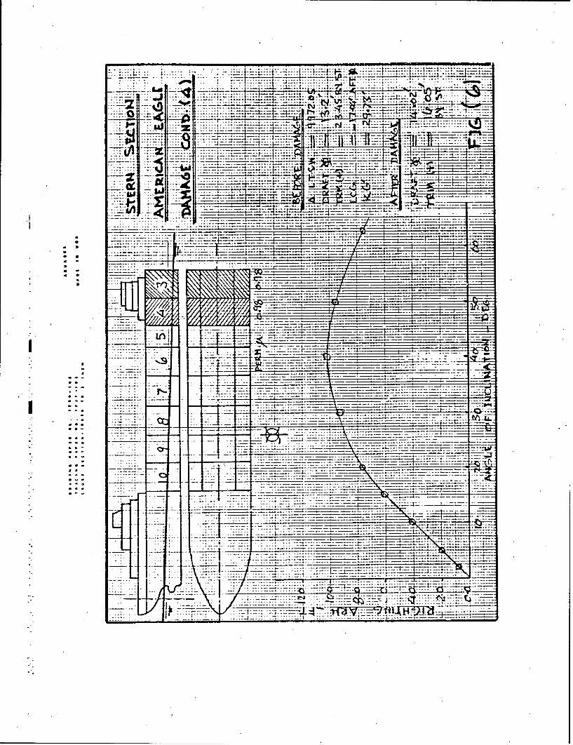
7 7*ý . ..............
7'. 7:. . .
_H 7____
=J -_
* L2
*Ln .... ....___ ._
... .. ..
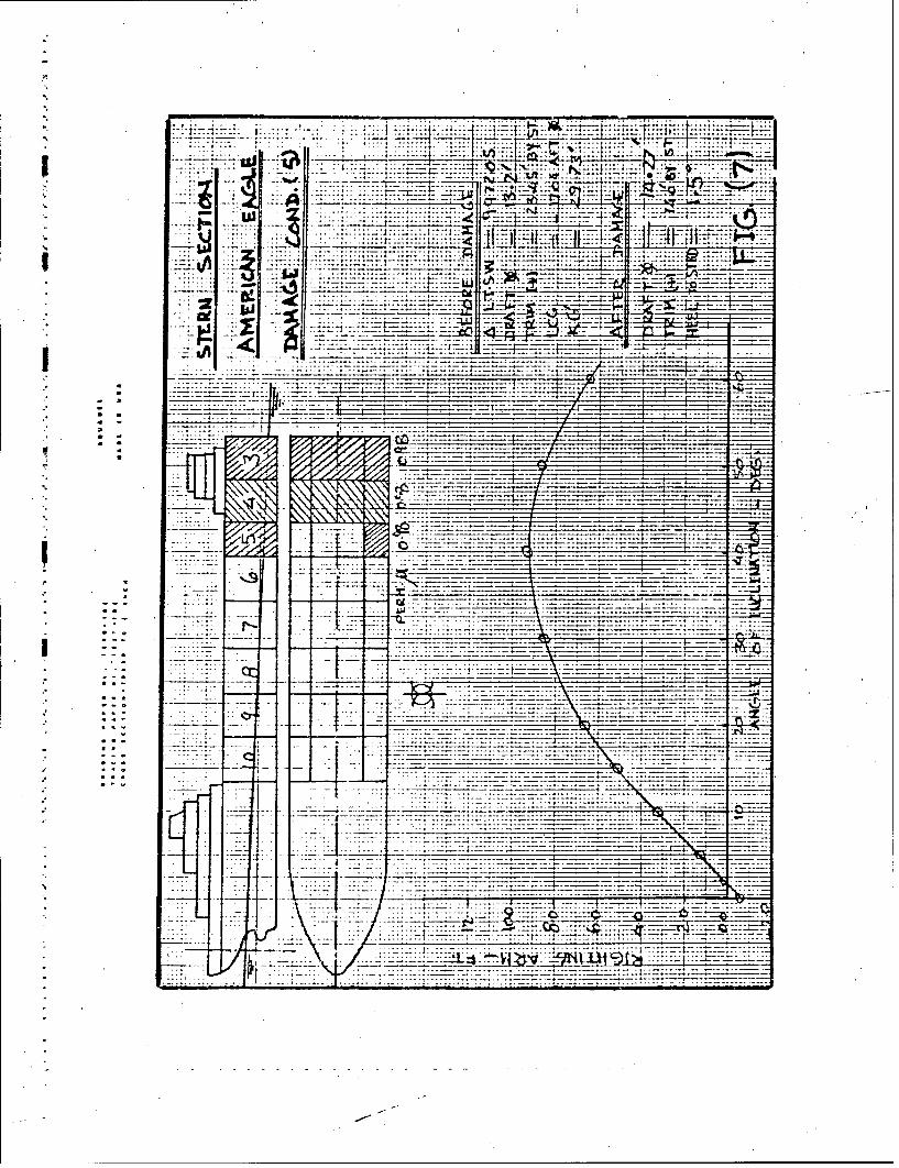
.. , . ...........
.....;. * ... ...:........__ _ _ _ __ _ _ __ _ _ _
_7-W - -__ _ -
a-7-
..... .... .... ........ . . . . . . . .
- _ .- 7-77---
~. ........
Cc.7
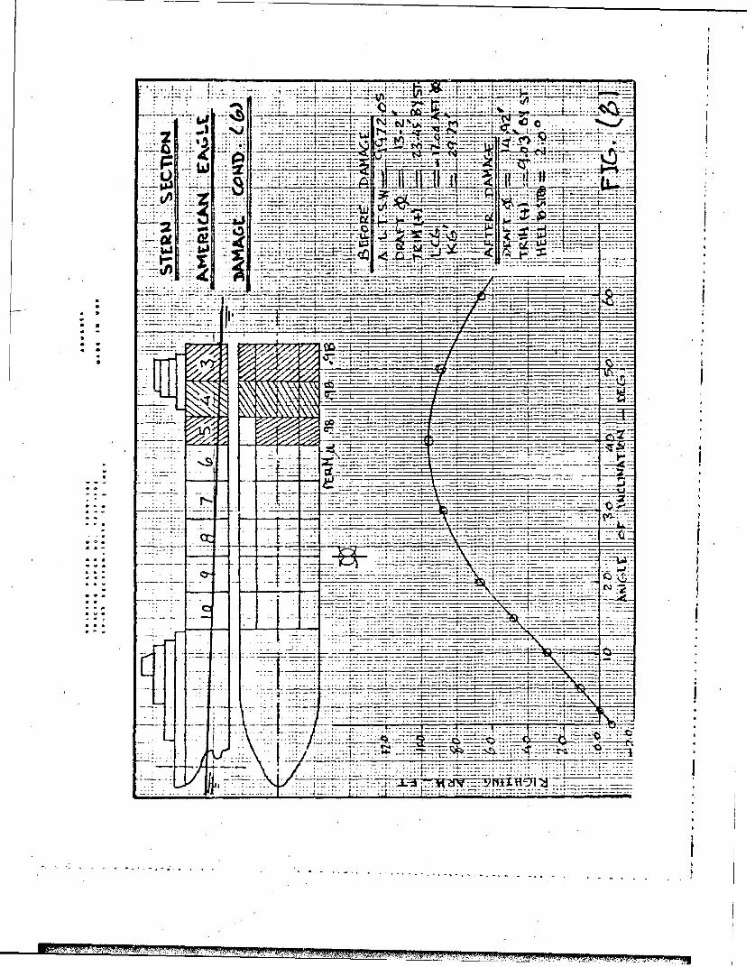
.. ....... ~- ~ -.
-~ ---- ---
7 7
*~~~~ ------ ---------- ~
-- -- -- - _ _ _ _ _
.. ... .. ...___
______
.L 21_4_==4
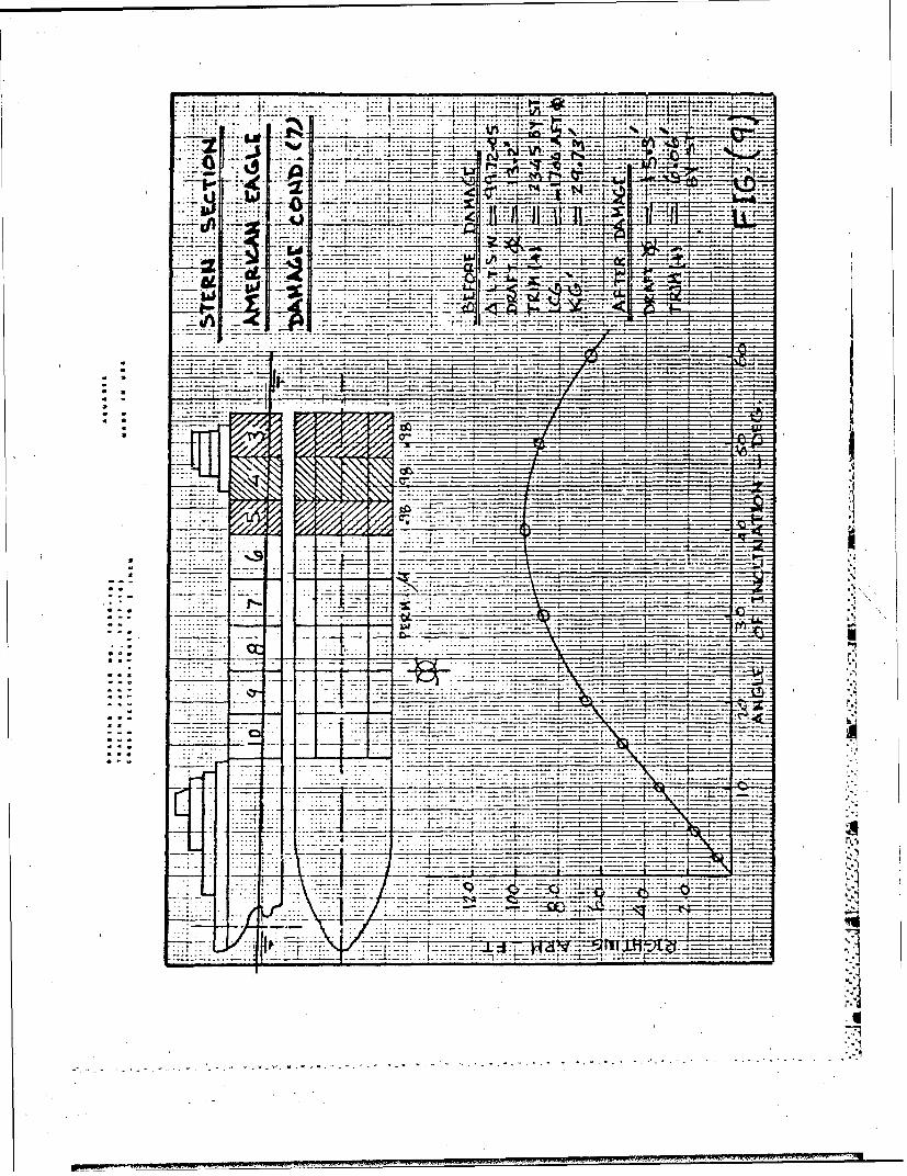
.........7 .........
. ..... . . . .....7- _ _ _
* a.7
S.-7
. . . .. . ..
7*.77:a---- 77 7
7_ _ _ 7.H 7
.. .......77J
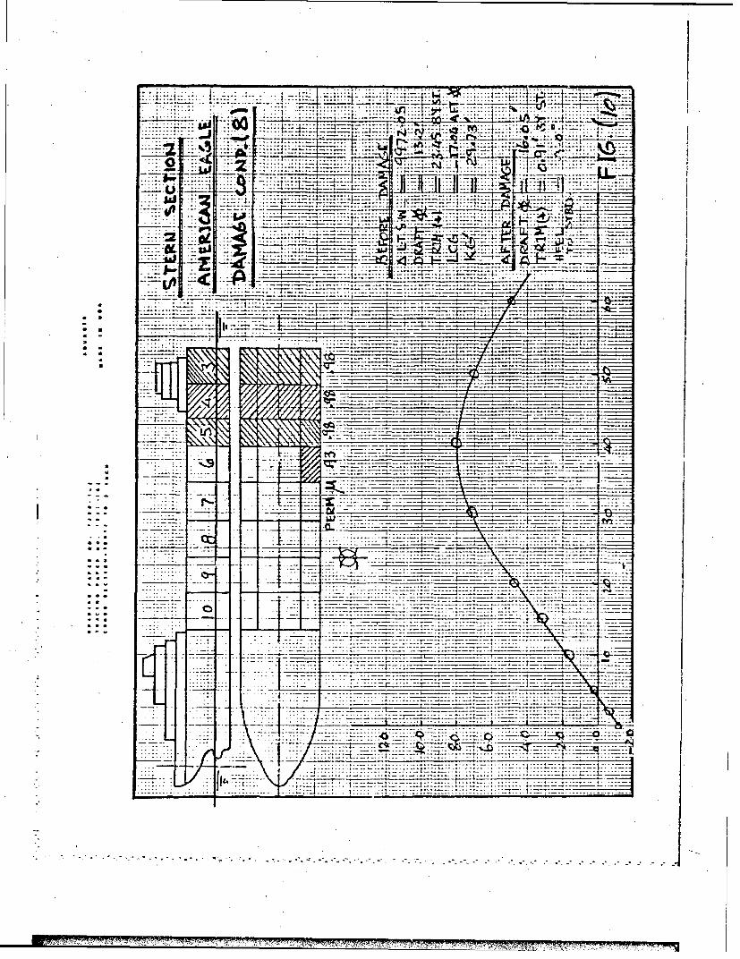
.. .......... E ~.. ........ . .. .... ..... ... ..
7. LuJ W
.. .. . . . . . .
-IF
-4 .. ..
-- -- -- -
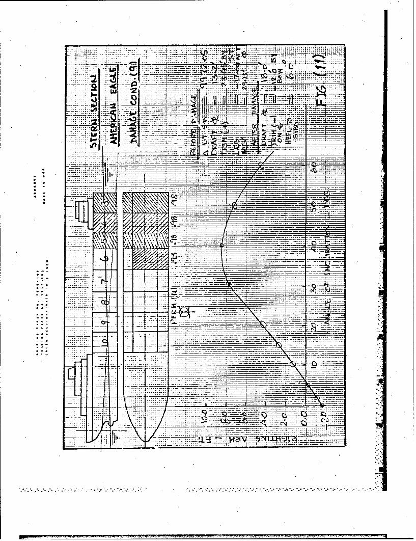
___7 ::;7:_ ___
* .. . .. ~~~. . ......... t ~ . ~ :Z Z .
*7-1
.zu4i
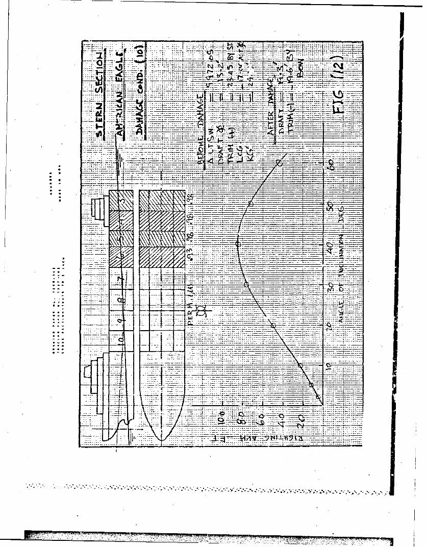
:..-f
7;
. ~~ . . . . . ...

.. ........ 5~ (~ h j- ~-.~2 :~~
4 :..... ..
_ 44 1 _ _ _
-- - - - - .. . .
---- - --
S~t t_____
F'7- _ _7
.: .........
-t - - - - -- - -
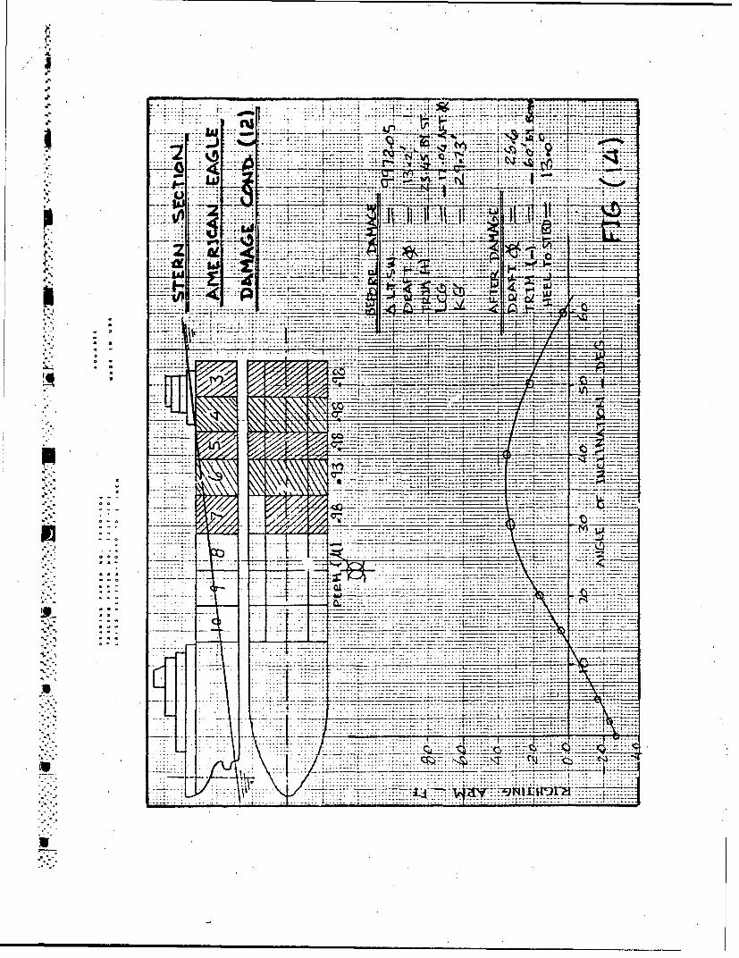
AL
.. . .. . .. . ... .
.7~~ 7ý ........
*~~~ s t- *II t 1...........
-- :- -- -- -- -
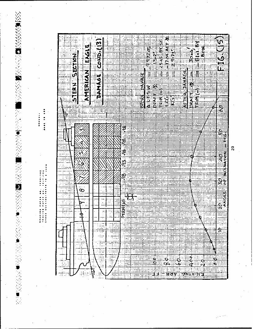
... .....
-72-1 '2 r4F~
*~~4l .......4 i~ .zz.
..........--. - ----- --- *- - .
7- = ,
* ~ ~ ~ ----- .................. ....... _
-4-4
..... .. .... C~
.2 -t::2~1
U7
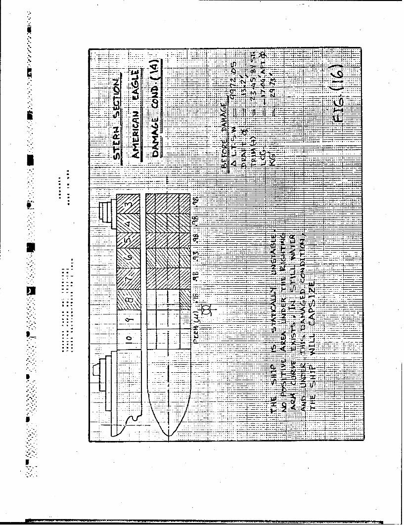
W~~~ - T---
__._kw 4434
,:± _ _ ---------- -- j
Cr .... ......
Iý

3. Longitudinal Strength in Still Water just before Explosion
The light ship weight distribution curve was supplied by the Marine Boardof Investigation. Using this curve and the loading condition of the shipbefore the explosion, the weight distribution curve was constructed. 7helongitudinzl strength analysis was performed using the SHCP coirputerprogram. Weight, buoyancy and shear force diagrams are shown in Figure17. The maximum shear force occurs at 170 ft aft of the forwardperpendicuihr (FP). The shear force at this locatiun is 1821 long tons.
4. Bulkhead Str,.ngth
SRef: (a) Roark, R.J., 'Formulas for Stress and Strain,' McGraw-Hill BookCompany, Fourth Edition, 1965.,(b) "A Guide for the Analysis of Ship St-uctures,' Thein Wah, Editor,U.S. Department of Commerce, 1960.(c) Jones, Norman, 'Plastic Behavior of Ship Structures,' Transactions,
The Society of Naval Architects and Mar Lne Engineers, 1976.
Various calculations were performed to detemine the strength of thetransverse cargo tank bulkheads, based on the original design scantlingsprovided by the bulkhead drawL;.. An estimate of the strength was alsomade with reduced plating thickness due to corrosion. An exactdetermination of the hydrostatic pressure necessary to cause rupture of astiffened panel bulklead can be an extremely cumbersome, if not impossibletask. Bow*ver, a reasonable estimate of the pressure at which thebulkhead will begin to plastically yield is possible. Further estimatescan be made for the pressure at which ultimate failure or plastic collapseoccurs. Several portions of the bulkhead must be considered in thisanalysis, i.e. panels with attached bulkhead stiffeners, unsupportedpanels between stiffeners, and bulkhead headers. This bulkhead consistsof six panels, arranged in decreasing thickness frcm the baseline, withthe upper two panels of increased thickness for corrosion considerations."Vertical stiffeners are spaced at 33-inch intervals (12" x 3.5" x 3/4'inverted angles). Four horizontal webs are located transversely acrossthe bulkhead (54" x 6" x 0.5').iA check was made to see if the bulkhead met the design rules of theAmerican Bureau of Shipping. The oldest set of rules readily available,"the 1965 Steel Vessel Rules, was used. The bulkhead plating met the ABSbulkhead thickness requirements if it were considered "protected plating"as defined in thE Rules. The sizes of the stiffeners exceeded the ABSrequirements by a small amount. The actual sizes of the headers exceededthe tabulated values in the rules of the ABS, and they would not failunder full head conditions.
22
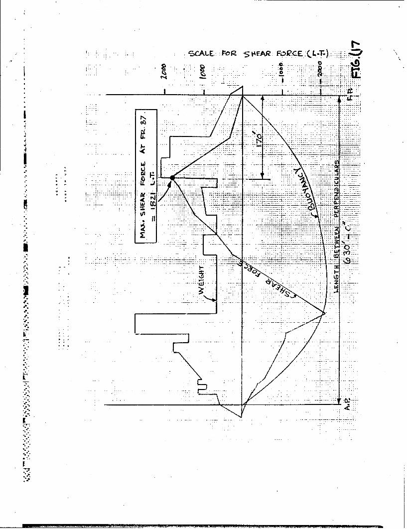
SECALEP R S;43EAR:
I~~~~. ...........I1U2Uji-7 - 7 . 7 7: - 7-,:!::: ::
77 =7-: 7.-
-77j
.1*e
.1. -
I-77
.. .... ...
Ar
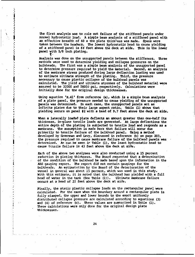
I
The first analysis was to rule out failure of the stiffened panels undernormal hydrostatic load. A simple beam analysis of a stiffened panel withan effective breadth of 60 x the plate thickress was made. Spans weretaken between the headers. The lowest hydrostatic head to cause yielding
. of a stiffened panel is 64 feet above the deck at side. 7his is the lowerpanel with 5/8 inch plating.
Analysis was done on the unsupported panels between the stiffeners. Threemethods were used to determine yielding and collapse pressures on thebulkheads. The first was a simple beam analysis of the unsupported panelto determine pressure required to yield the material. Second, an analysisof the membrane stress produced during large deflection loading was usedto estimate ultimate strength of the plating. Third, the pressurenecessary to cause plastic collapse of the bulkhead panels wascalculated. The yield and ultimate stresses of the bulkhead material wereassumed to be 32000 and 58000 psi, respectively. Calculations wereinitially done for the original design thicknesses.
Using equation 'X.41' from reference (a), 'which is a simple beam analysisof a plate panel, the pressure needed to cause yielding of the unsupportedpanels was determined. In each case, the unsupported panels act as"infinite plates due to their large aspect ratio. Table (1) shows thatyielding occurs on panel #2 with a head of 9.7 feet above the deck at side.
P
tWhen a laterally loaded plate deflects an amount greater than one-half itsthickness, in-plane tensile loads are generated. At large deflections theentire depth of the plating is subjected to tensile load and responds as amembrane. The assumption is made here that failure will occur dueprimarily to tensile failure of the bulkhead panel. Using a methoddeveloped by Greenman and Levy, discussed in reference (b) on page 203,the pressure required to cause membrane failure of the bulkhead panels wasdetermined. As can be seen ir Table (1), the least hydrostatic head tocause tvnsile failure is 43 feet above the deck at side.
Each of the above two analyses were also conducted using a 15 percentreduction in plating thickness. The Board requested that a determinationof the condition of the bulkhead be made based upon the information in theABS gauging report. The report did not contain gaugings for thebulkheads. An estimatation by the Board of the deterioration of thevessel in general was about 15 percent, which was used in this study.With this estimate, it is noted that the bulkhead has yielded with a fullhead of water in the tank (See Table (1)). Ultimate membrane failureoccurs at a head of 22 feet above the deck at side.
Finally, the static plastic collapse loads on the rectangular panel werecalculated. For the case when the boundary around a rectangular plate isfully clamped, the upper and lower bounds to the exact uniformlydistributed collapse pressure are calculated according to equations (3)
and (4) of reference (c). These values are summarized in Table (1).These calculations were only done for the original design platethicknesses.
24
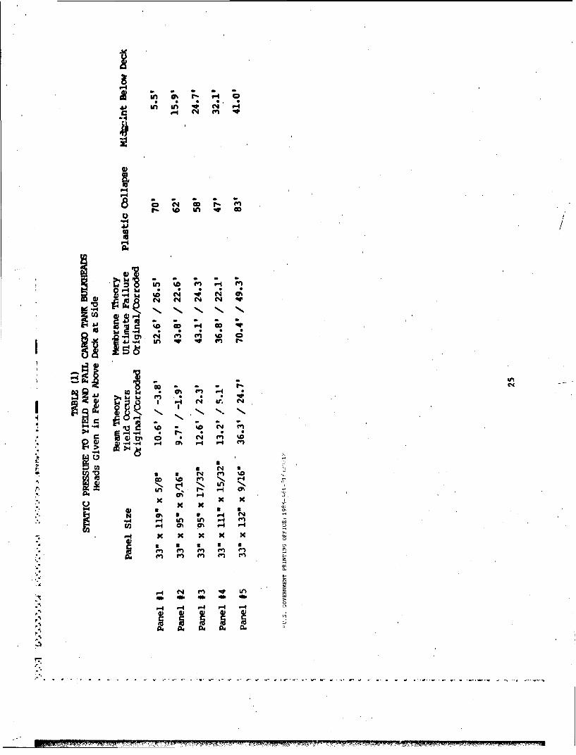
w in qw C
11% NN. 0, S
1- (4 ;o ;q ;
6,y
">4
0 )
4CJtn
en e
r-4- -4M qr L
r4 P- --