request for proposals - in.gov · indot 1-1 request for proposals i-65 southeast indiana project...
TRANSCRIPT

REQUEST FOR PROPOSALS
To Design and Construct
I-65 Southeast Indiana Project Through a Public Private Agreement
VOLUME II
TECHNICAL PROVISIONS
A Project of the
INDIANA DEPARTMENT OF TRANSPORTATION ISSUED DECEMBER 28, 2016
ADDENDUM 1 ISSUED JANUARY 23, 2017
Indiana Department of Transportation 100 North Senate Avenue, IGCN 755
Indianapolis, Indiana 46204

Indiana Department of Transportation Request for Proposals I-65 Southeast Indiana Project Technical Provisions JANUARY 23, 2017 ADDENDUM # 1 i
Technical Provisions Sections 1. General Scope of Work 2. Quality Management 3. Design Requirements 4. Construction Requirements 5. Public Involvement 6. Environmental 7. Roadway 8. Pavement 9. Drainage
10. Traffic 11. Maintenance of Traffic 12. Geotechnical 13. Structures 14. Utilities 15. Railroads 16. Intelligent Transportation Systems 17. Right of Way
List of Attachments 1-1 Unique Special Provisions (USP): General 3-1 Applicable Standards 4-1 USP: Construction 6-1 Environmental Commitments 6-2 Non-Permitted Wetland Areas 7-1 USP: Roadway 8-1 USP: Pavement 8-2 IRI For Smoothness Testing 8-3 Certified Hot Mix Asphalt Producer Program 8-4 Additional Specifications 8-5 Patching Locations 9-1 USP: Drainage 9-2 NOT USED 9-3 Pipe Ratings
10-1 USP: Traffic 11-1 USP: Maintenance of Traffic 13-1 USP: Structures 15-1 NOT USED 16-1 USP: Intelligent Transportation Systems
TECHNICAL PROVISIONS – Section 1 General Scope of Work
INDOT 1-1 Request for Proposals I-65 SOUTHEAST INDIANA PROJECT Technical Provisions JANUARY 23, 2017 ADDENDUM # 1
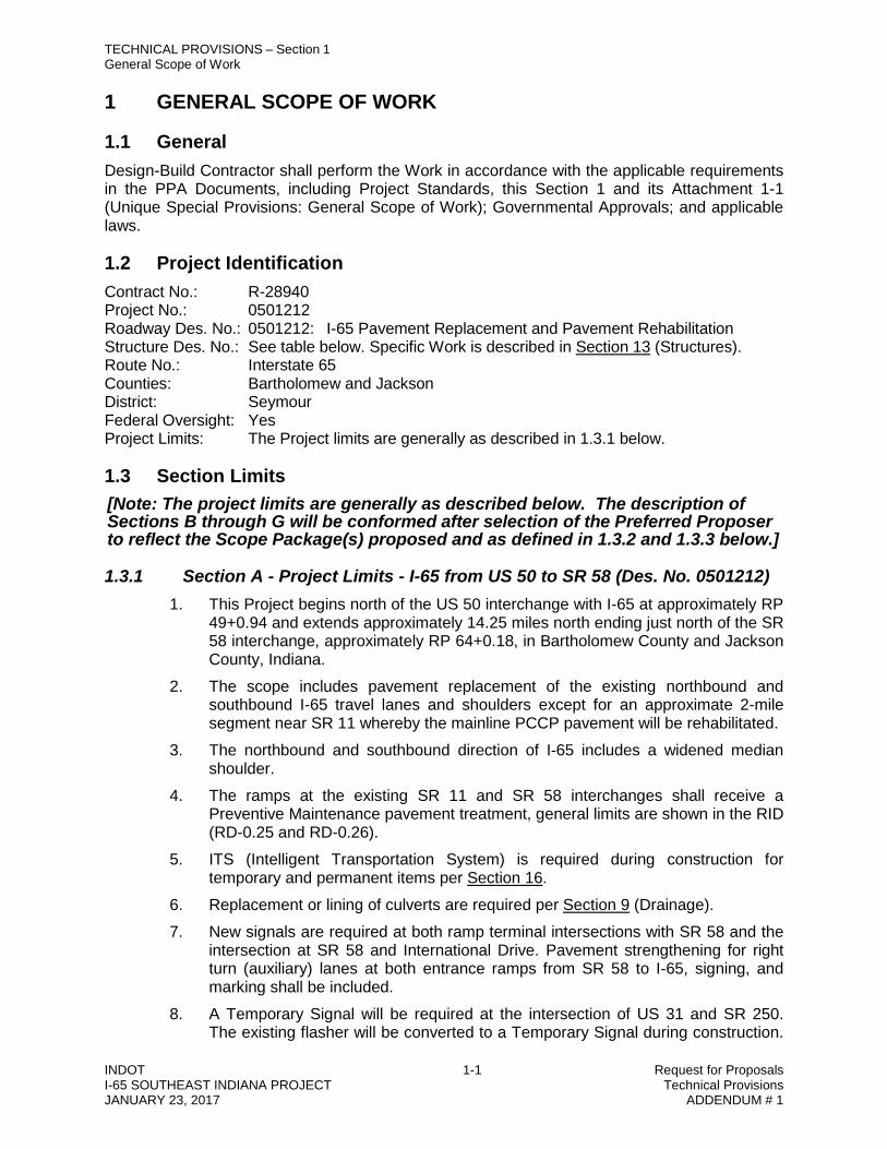
1 GENERAL SCOPE OF WORK
1.1 General Design-Build Contractor shall perform the Work in accordance with the applicable requirements in the PPA Documents, including Project Standards, this Section 1 and its Attachment 1-1 (Unique Special Provisions: General Scope of Work); Governmental Approvals; and applicable laws.
1.2 Project Identification Contract No.: R-28940 Project No.: 0501212 Roadway Des. No.: 0501212: I-65 Pavement Replacement and Pavement Rehabilitation Structure Des. No.: See table below. Specific Work is described in Section 13 (Structures). Route No.: Interstate 65 Counties: Bartholomew and Jackson District: Seymour Federal Oversight: Yes Project Limits: The Project limits are generally as described in 1.3.1 below.
1.3 Section Limits [Note: The project limits are generally as described below. The description of Sections B through G will be conformed after selection of the Preferred Proposer to reflect the Scope Package(s) proposed and as defined in 1.3.2 and 1.3.3 below.]
1.3.1 Section A - Project Limits - I-65 from US 50 to SR 58 (Des. No. 0501212) 1. This Project begins north of the US 50 interchange with I-65 at approximately RP
49+0.94 and extends approximately 14.25 miles north ending just north of the SR 58 interchange, approximately RP 64+0.18, in Bartholomew County and Jackson County, Indiana.
2. The scope includes pavement replacement of the existing northbound and southbound I-65 travel lanes and shoulders except for an approximate 2-mile segment near SR 11 whereby the mainline PCCP pavement will be rehabilitated.
3. The northbound and southbound direction of I-65 includes a widened median shoulder.
4. The ramps at the existing SR 11 and SR 58 interchanges shall receive a Preventive Maintenance pavement treatment, general limits are shown in the RID (RD-0.25 and RD-0.26).
5. ITS (Intelligent Transportation System) is required during construction for temporary and permanent items per Section 16.
6. Replacement or lining of culverts are required per Section 9 (Drainage). 7. New signals are required at both ramp terminal intersections with SR 58 and the
intersection at SR 58 and International Drive. Pavement strengthening for right turn (auxiliary) lanes at both entrance ramps from SR 58 to I-65, signing, and marking shall be included.
8. A Temporary Signal will be required at the intersection of US 31 and SR 250. The existing flasher will be converted to a Temporary Signal during construction.

TECHNICAL PROVISIONS – Section 1 General Scope of Work
INDOT 1-2 Request for Proposals I-65 SOUTHEAST INDIANA PROJECT Technical Provisions JANUARY 23, 2017 ADDENDUM # 1
The temporary signal will be returned to a flasher at completion of the project as directed by the Seymour District Traffic Engineer.
9. Section A includes work on the following Bridges:
Bridge No. Des. No.
Existing Structure Number
Proposed Structure Number Description
Type of Work
3 1601732 I65-050-02226 CNBL
I65-050-02226 DNBL I65 over CSX Railroad Preserve and
Rehabilitate
4 1601733 I65-050-02226 CSBL
I65-050-02226 DSBL I65 over CSX Railroad Widening and
Rehabilitate
6 1592538 I65-051-04255 BNBL
I65-051-04255 CNBL
I65 over Branch Mutton Creek Ditch
Preserve and Rehabilitate
7 1592536 I65-051-04255 JBSBL
I65-051-04255 JCSBL
I65 over Branch Mutton Creek Ditch
Widening and Rehabilitate
10 1601840 I65-054-04651 CNBL
I65-054-04651 DNBL
I65 over East Fork of White River
Widening and Rehabilitate
11 1601970 I65-054-04651 CSBL
I65-054-04651 DSBL
I65 over East Fork of White River
Widening and Rehabilitate
12 1601841 I65-054-04652 CNBL
I65-054-04652 DNBL
I65 over East Fork of White River, Overflow No. 1
Widening and Rehabilitate
13 1601920 I65-054-04652 CSBL
I65-054-04652 DSBL
I65 over East Fork of White River, Overflow No. 1
Widening and Rehabilitate
14 1592568 I65-054-04653 BNBL
I65-054-04653 CNBL
I65 over East Fork of White River Overflow No. 2
Widening and Rehabilitate
15 1592576 I65-054-04653 BSBL
I65-054-04653 CSBL
I65 over East Fork of White River Overflow No. 2
Widening and Rehabilitate
16 1592575 I65-055-04654 BNBL
I65-055-04654 CNBL
I65 over East Fork of White River Overflow No. 3
Widening and Rehabilitate
17 1592589 I65-055-04654 BSBL
I65-055-04654 CSBL
I65 over East Fork of White River Overflow No. 3
Widening and Rehabilitate
19 1592590 I65-056-02284 BNBL
I65-056-02284 CNBL I65 over L & I Railroad Widening and
Rehabilitate
20 1592592 I65-056-02284 BSBL
I65-056-02284 CSBL I65 over L & I Railroad Widening and
Rehabilitate
21 1592595 I65-056-04656 BNBL
I65-056-04656 CNBL I65 over Able Ditch Widening and
Rehabilitate
22 1592594 I65-056-04656 BSBL
I65-056-04656 CSBL I65 over Able Ditch Widening and
Rehabilitate
25 1592600 I65-061-04660 BNBL
I65-061-04660 CNBL I65 over Smalls Creek Preserve and
Rehabilitate
26 1592599 I65-061-04660 JBSBL
I65-061-04660 JCSBL I65 over Smalls Creek Widening and
Rehabilitate

TECHNICAL PROVISIONS – Section 1 General Scope of Work
INDOT 1-3 Request for Proposals I-65 SOUTHEAST INDIANA PROJECT Technical Provisions JANUARY 23, 2017 ADDENDUM # 1
1.3.2 Section B – Open I-65 Added Travel Lanes (Des. No. 0501212)
Section B includes opening the future added travel lanes as defined in Section A to traffic within the project limits including pavement markings, shoulder corrugations, and updating the CE-4 Environmental Document with an AI (Additional Information) and obtain the necessary approvals (including noise study and determination of noise wall locations if needed) to open the added travel lanes as part of the overall project.
1.3.3 Section C - Replacement of I-65 PCCP Pavement (Des. No. 0501212)
Section C includes pavement replacement in the northbound and southbound I-65 mainline travel lanes (north and south of the SR 11 Interchange) within the following Project limits;
(a) Section C1: Replace NB – 2411+09 to 2415+05
Replace NB – 2525+89 to 2529+86
(b) Section C2: Replace SB - 2411+09 to 2415+05
Replace SB – 2525+89 to 2529+86
(c) Section C3: Replace NB - 2430+64 to 2474+04
(d) Section C4: Replace SB – 2430+64 to 2474+04
(e) Section C5: Replace NB - 2477+87 to 2513+04
(f) Section C6: Replace SB - 2477+30 to 2512+31
Notes:
1. Section C replaces 1.3.1.2, in whole or partially as selected. 2. Station limits are approximate. 3. Work do not include approach slabs
1.3.4 Section D - Overhead Bridge Rehabilitation
Section D includes the rehabilitation of the bridges over I-65 listed below. Bridge
No. Des. No. Existing Structure Number
Proposed Structure Number Description Type of
Work 5 1700256 I65-052-04254 A I65-052-04254 B Enos Road over I65 Rehabilitate
8 1700257 I65-052-05042 I65-052-05042 A CR 800 North over I65 Rehabilitate
9 1700258 I65-053-04650 I65-053-04650 A Redding Road over I65 Rehabilitate
18 1700259 (11)31A-36-04655 B (11)31A-36-04655 C SR 11 over I65 Rehabilitate
23 1700260 I65-057-04657 I65-057-04657 A Countyline Road over I65 Rehabilitate
24 1700261 I65-058-04658 I65-058-04658 A CR 950 South over I65 Rehabilitate
27 1700262 I65-062-04659 I65-062-04659 A CR 625 South over I65 Rehabilitate

TECHNICAL PROVISIONS – Section 1 General Scope of Work
INDOT 1-4 Request for Proposals I-65 SOUTHEAST INDIANA PROJECT Technical Provisions JANUARY 23, 2017 ADDENDUM # 1
(a) Section D1 is Bridge No. 23, Countyline Road over I65
(b) Section D2 is Bridge No. 27, CR 625 South over I65
(c) Section D3 is Bridge No. 24, CR 950 South over I65
(d) Section D4 is Bridge No. 9, Redding Road over I65
(e) Section D5 is Bridge No. 8, CR 800 North over I65
(f) Section D6 is Bridge No. 18, SR 11 over I65
(g) Section D7 is Bridge No. 5, Enos Road over I65
(h) Provide update to the CE-4 Environmental Document with an AI (Additional Information) and obtain the necessary approvals prior to construction of the Section D overhead bridges.
1.3.5 Section E - Pavement Rehabilitation - SR 58 to SR 46 (Des. No. 1296263)
Section E includes HMA pavement resurfacing in the northbound and southbound I-65 travel lanes and shoulders, concrete pavement restoration of northbound and southbound I-65 travel lanes and shoulders and ramps near the SR 46 interchange located north of Section A Project limits; according to the following:
(a) RP 64+0.18 to RP 69+0.06 (N. of SR 58 to SR 46)
(b) INDOT will provide a Programmatic Environmental document for Section E 1.3.6 Section F - I-65 Mainline Bridge Rehabilitation (over Denois Creek)
Section F includes the rehabilitation of the I-65 mainline bridges listed below. Bridge
No. Des. No. Existing Structure Number
Proposed Structure Number Description Type of
Work 30 1383528 I65-065-04663 ANBL I65-065-04663 BNBL I65 over Denois Creek Rehabilitate
31 1383529 I65-065-04663 ASBL I65-065-04663 BSBL I65 over Denois Creek Rehabilitate
(a) Section F1 is Bridge No. 30, I65 NB over Denois Creek
(b) Section F2 is Bridge No. 31, I65 SB over Denois Creek
(c) INDOT will provide a Programmatic Environmental document for Section F.
1.3.7 Section G - Additional ITS (Message Signs and Fiber Optic Backbone)
(a) Section G1: Provide and install variable message signs at 2 locations:
(1) NB I-65 south of SR 50 Interchange
(2) SB I-65 south of SR 46 Interchange
(b) Section G2: Provide and install fiber optic backbone in Section A project limits.

TECHNICAL PROVISIONS – Section 1 General Scope of Work
INDOT 1-5 Request for Proposals I-65 SOUTHEAST INDIANA PROJECT Technical Provisions JANUARY 23, 2017 ADDENDUM # 1
(c) Provide necessary Environmental Document and obtain the necessary approvals prior to installation of ITS items.
(d) Provide update the 401/404 permit as necessary and obtain approvals prior to installation of ITS items.
1.4 Project Management 1.4.1 Key Personnel
Design-Build Contractor shall provide Key Personnel in accordance with Section 7.3 of the PPA. The following describes the roles and responsibilities of the Key Personnel:
1. Project Manager: Design-Build Contractor’s designated individual as its single point of contact for purposes of overall administration of the project, and who is authorized to act on its behalf with respect to contractual matters and for resolving any and all issues that may arise between Design-Build Contractor and INDOT during progress of the Work.
2. Construction Manager: Design-Build Contractor’s designated individual who is responsible for oversight and management of all construction and other field activities related to the project. The Construction Manager shall be different from and report to Design-Build Contractor’s Project Manager.
3. Construction Superintendent: Design-Build Contractor’s designated individual who is responsible for supervision of all field activities. The Construction Superintendent may be the Construction Manager or an individual who reports directly to the Construction Manager. If the Construction Superintendent is also the Construction Manager, then the Construction Superintendent may not serve in any other additional role. If the Construction Superintendent does not also serve as the Construction Manager, then the Construction Superintendent may fill one other Key Personnel Role if qualified.
4. Lead Engineer: The Designer’s Engineer who will manage all Work performed by Design-Build Contractor’s Designer including management of any Design Work support during construction, such as design changes and the completion of Record Drawings. The Lead Engineer is responsible for releasing Design Documents for construction, reviewing all construction documents, and certifying that all Released for Construction Documents, conform to the requirements of the Technical Provisions and the PPA. The Lead Engineer must be a Registered Professional Engineer in Indiana.
5. Storm Water Quality Manager: Design-Build Contractor’s designated individual who is responsible for the installation, inspection, maintenance and removal of all required storm water management measures and implementation of the Contractor’s Storm Water Quality Control Plan. The SWQM shall meet the requirements of 205.03(b)1, and hold a current certification as a CESSWI, or a CESSWI In-Training, or a CISEC, or a CISEC In-Training, or a CPESC, or a CPESC In-Training, or an approved equivalent. For additional requirements, refer to the Department Standard Specifications and Recurring Special Provision 205-R-636.
6. Design Quality Manager: The Designer’s Engineer who is responsible for Design QA/QC for all Design Work that is performed for the project, including any design changes during construction and the production of Record Drawings. The Design Quality Manager shall include a certification with each design Submittal that all necessary

TECHNICAL PROVISIONS – Section 1 General Scope of Work
INDOT 1-6 Request for Proposals I-65 SOUTHEAST INDIANA PROJECT Technical Provisions JANUARY 23, 2017 ADDENDUM # 1
)
Design QC checks have been completed and that any design changes resulting from such checks are incorporated in the Submittal.
7. Maintenance of Traffic (MOT) Manager: See Section 11.3.6 for roles and responsibilities. The MOT Manager shall be certified by the American Traffic Safety Service Association, ATSSA, or approved equal certifying organization in accordance with Standard Specification 801.03. The MOT Manager shall be different from and report to the Construction Superintendent.
8. Certified INDOT Utility Coordinator: Design-Build Contractor’s designated individual who is certified through INDOT’s Utility Coordinator Certification Training, and who is responsible for completing the utility coordination process as defined in the Indiana Design Manual Chapter 104, 105 IAC 13, and the INDOT Utility Accommodation Policy.
9. Public Involvement Manager (PIM) is responsible for identifying public information issues related to the Design – Build Contractor’s work, and for formulating and implementing strategies to address issues relevant to the public, public and resource agencies, emergency service providers, businesses, media and other interested parties. The PIM shall work with INDOT to respond to the communication needs of the project with availability by telephone and email. During critical construction activities and emergencies, the PIM shall be available as needed.
10. Environmental Compliance Manager (ECM) will be responsible for implementation of all the environmental design and construction commitments and conditions identified in the approved environmental document and permits. The ECM would be a full–time, on-site staff member and report to the Design-Build Contractor’s Project Manager. The ECM shall have a minimum of 5 years of experience with a demonstrated expertise with construction management, permitting compliance and overall environmental compliance with transportation projects. The ECM shall have the authority to stop or redirect construction work as needed at any time to maintain environmental compliance for the project. The ECM would be primary liaison with INDOT for any environmental issues.
1.4.2 Project Administration
1.4.2.1 Project Baseline Schedule
Design-Build Contractor shall provide the Project Baseline Schedule and the Preliminary Project Baseline Schedule which shall conform to the “Baseline CPM Schedule” in Recurring Special Provision 108-C-215. Design-Build Contractor shall submit the Project Baseline Schedule for approval by INDOT in its sole discretion. INDOT will review the Project Baseline Schedule in accordance with Recurring Special Provision 108-C-215.
Each activity on the Project Baseline Schedule shall be assigned a cost by Design-Build Contractor for the purposes of calculating and tracking earned value. The cost loading of the schedule will be reviewed by INDOT as described in preceding paragraph.
1.4.2.2 Project Status Schedule
Design-Build Contractor shall submit to INDOT Project Status Schedule updates to reflect the current status of the Project including recovery schedules, schedule revisions due to Change Requests, and approved Change Orders.

TECHNICAL PROVISIONS – Section 1 General Scope of Work
INDOT 1-7 Request for Proposals I-65 SOUTHEAST INDIANA PROJECT Technical Provisions JANUARY 23, 2017 ADDENDUM # 1
The Project Status Schedule shall conform to the “Monthly Update CPM Schedule” in Recurring Special Provision 108-C-215. The Project Status Schedule shall be submitted to INDOT in accordance with Recurring Special Provision 108-C-215 for approval. If the Project Status Schedule is not submitted by the required date INDOT may withhold or adjust Progress Payments.
1.4.2.3 As-Built Schedule
Design-Build Contractor shall submit an “as-built schedule” in conformance with the “Final CPM Schedule” in Recurring Special Provision 108-C-215. The “as-built schedule” shall be submitted to INDOT in accordance with Recurring Special Provision 108-C-215 for approval.
1.4.2.4 Revisions
If it becomes necessary to add, combine, eliminate, or modify schedule Activities to reflect modifications to the Work, such changes shall be made through a Change Order that has been issued by INDOT, and therefore reflected in the Project Schedule. Revisions to the Project Schedule and consequent realignment of funds between payment activities may be requested by Design-Build Contractor in accordance with, and subject to, Section 13 of the PPA.
1.4.2.5 Time Impact Analysis
1. As part of a Change Request as set forth in Section13 of the PPA Design-Build Contractor shall submit to INDOT a written time impact analysis illustrating the influence of each claimed delay. Each time impact analysis shall include a fragmentary network demonstrating how Design-Build Contractor proposes to incorporate the change, delay, or Design-Build Contractor request into the current Project Status Schedule. The time impact analysis shall demonstrate the time impact to each and every affected schedule Activity in the most recent Project Status Schedule at the time of the occurrence.
2. The time impact analysis Submittal shall include the details of the change, including added, changed or deleted data for schedule Activities and logic. If the current Project Status Schedule is revised subsequent to submittal of a time impact analysis but prior to its approval, Design-Build Contractor shall promptly indicate in writing to INDOT the need for any modification to its time impact analysis.
3. Design-Build Contractor shall submit one printed Gantt chart including all schedule Activities affected by the time impact analysis, grouped and sorted by WBS and compared to the current Project Baseline Schedule. In addition, Design-Build Contractor shall provide one electronic backup of the Project Schedule with the time impact analysis and a comprehensive narrative for each Change Request. Design-Build Contractor shall incorporate the results of the Change Request from INDOT into the Project Status Schedule for the next Progress Report.
1.4.2.6 Recovery Schedule
If the Work is delayed on any Controlling Work Item for a period which exceeds the greater of either thirty days in the aggregate or that number of days in the aggregate equal to five percent of the days remaining until Substantial Completion, the next Project Status Schedule shall include a Recovery Schedule demonstrating the proposed plan to regain lost Project Schedule progress and to achieve Substantial Completion by the specified date.

TECHNICAL PROVISIONS – Section 1 General Scope of Work
INDOT 1-8 Request for Proposals I-65 SOUTHEAST INDIANA PROJECT Technical Provisions JANUARY 23, 2017 ADDENDUM # 1
1.4.3 Project Management Plan
Design-Build Contractor shall prepare a Project Management Plan (PMP), which is an umbrella document that describes Design-Build Contractor’s managerial approach, strategy, and quality procedures to design and build the Project and achieve all requirements of the PPA Documents.
INDOT will audit and monitor the activities described in the PMP to assess Design-Build Contractor performance. All commitments and requirements contained in the PMP shall be verifiable.
The PMP shall be submitted for INDOT approval in accordance with Section 2.1.1 of the PPA. The general outline and minimum content of the PMP shall be as follows:
1.4.3.1 Project Administration
1. Organizational diagram 2. Personnel names and contact details, titles, and job roles 3. Design-Build Contractor’s Contracting Plan 4. Project Baseline Schedule 5. Quality Control procedures to establish and encourage continuous improvement 6. Audit 7. Procedures to facilitate review and audit by INDOT 8. Auditing and management review of Design-Build Contractor’s own activities
under the PMP 9. PMP Update - Procedures for preparation of amendments and submission of
amendments to any part of the PMP 10. Document Management - The manner in which records will be maintained in
compliance with the Technical Provisions, including any specific systems Design-Build Contractor will use.
1.4.3.2 Quality Management Plan
1. Organizational structure covering the activities to be performed in accordance with the PPA Documents
2. Personnel - Resource plan for Design-Build Contractor and its Subcontractors 3. Arrangements for coordinating and managing staff interaction with INDOT and its
consultants, including Key Personnel and description of approach to coordinating Work of off-site personnel
4. Names and contact details, titles, job roles and specific experience required for the Key Personnel and for other principal personnel during design
5. Names and contact details, titles, job roles of principal personnel for Design-Build Contractors and any third party with which Design-Build Contractor will coordinate activities
6. Design QA/QC Plan a. Arrangements for coordinating and managing staff interaction with INDOT and its

TECHNICAL PROVISIONS – Section 1 General Scope of Work
INDOT 1-9 Request for Proposals I-65 SOUTHEAST INDIANA PROJECT Technical Provisions JANUARY 23, 2017 ADDENDUM # 1
consultants, including Key Personnel and description of approach to coordinating Work of off-site personnel
b. Responsibility of Design-Build Contractor and Affiliates, including constructability reviews
c. Steps taken to ensure Design-Build Contractor and Suppliers meet the obligations imposed by their respective Contracts
d. Interfaces between Design-Build Contractor, Subcontractors, and independent certifiers during design, including interfaces between the structural design auditor, the safety auditor, and quality reviewers
e. Coordination with Utility Owners f. Procedures describing how the principal activities will be performed during the
design stage: to include geotechnical site investigation, surveys and mapping, environmental management, safety audit, structural audit, and checking
g. QA/QC procedures, including a resource table for monitoring and auditing all design services, design review and certification, verification of Plans and Working Drawings; NDCs, FDCs; and Witness Points and Hold Points in Section 2 (Quality Management).
h. Procedures to establish Design-Build Contractor’s Hold Points in design process where checking and review will take place
i. Procedures to ensure accuracy, completion, and quality in Submittals to INDOT and Governmental Entities
j. Procedures to establish and encourage continuous improvement, including corrective and preventive action
7. Construction Quality Management Plan Complete procedures for preparing for and complying with Construction Hold Points in Section 2 (Quality Management).
1.4.3.3 Environmental Management
1. Organization - Design-Build Contractor's main contractual arrangements 2. Organizational structure covering the activities to be performed in accordance
with the PPA Documents 3. Environmental Contact Tree 4. Personnel - Resource plan for Design-Build Contractor and its Subcontractors
a. Arrangements for coordinating and managing staff interaction with INDOT and its consultants, including Key Personnel and description of approach to coordinating Work of off-site personnel
b. Names and contact details, titles, job roles and specific experience required for Key Personnel and for other environmental personnel
5. Subcontractors - Overall control procedures for subcontractors, including consultants and subconsultants
6. Environmental Compliance and Mitigation Plan 7. Spill Prevention Plan

TECHNICAL PROVISIONS – Section 1 General Scope of Work
INDOT 1-10 Request for Proposals I-65 SOUTHEAST INDIANA PROJECT Technical Provisions JANUARY 23, 2017 ADDENDUM # 1
1.4.3.4 Safety Plan
1. Organization – Personnel, policies, plans, training programs, Work Site controls, and Incident management and response plans to ensure the health and safety of personnel involved in the Project and the general public affected by the Project
2. Procedures for immediately notifying INDOT of all incidents arising out of or in connection with the performance of the Work
1.4.3.5 Communications Plan
1. The manner in which Design-Build Contractor’s organization will respond to unexpected requests for information, communicate changes or revisions to necessary Design-Build Contractor personnel, and notify affected stakeholders before and after changes are made
2. Processes and procedures for communication of Project information between Design-Build Contractor’s organization, INDOT, the Department, permitting agencies, utilities, other third parties and the public.
1.4.3.6 Updates to the PMP
Design-Build Contractor shall provide a revised PMP to INDOT for approval in its sole discretion.
Propose updates to the PMP and, as applicable, affected components in the event of the following:
• The occurrence of any changes to Key Personnel, Quality Plan, Safety Plan, Project Schedule, project administration policies and procedures
• The occurrence of other changes necessitating revision to the PMP
• As otherwise directed by INDOT 1.4.4 Document Management
In the provision of a document management system, Design-Build Contractor shall:
1. Use data protocols, standards, and procedures compatible with those employed by INDOT and implement any new operating practices required as a result of INDOT’s amendments to any such systems, standards, and procedures.
2. Provide a secure location for any interface as may be provided by INDOT, such that only authorized users have access and that it is protected from loss, theft, damage, unauthorized or malicious use.
3. Employ appropriate standards and procedures, and train Design-Build Contractor personnel to operate any INDOT data management system which INDOT may require in connection with the Project.
4. Design-Build Contractor shall train INDOT personnel to operate any Design-Build Contractor data management system approved by INDOT for Design-Build Contractor use in connection with the Project.

TECHNICAL PROVISIONS – Section 1 General Scope of Work
INDOT 1-11 Request for Proposals I-65 SOUTHEAST INDIANA PROJECT Technical Provisions JANUARY 23, 2017 ADDENDUM # 1
5. Provide a mechanism for the electronic transfer of meta-data along with the associated portable document format (PDF) images for uploading into an Electronic Document Management System (EDMS).
6. Provide INDOT with procedures and software for accessing all Project-related documents as a component of Design-Build Contractor’s obligations under Section 21 of the PPA.
All Project-related documents shall be provided to INDOT in a searchable electronic format and legible.
In the Project Management Plan, Design-Build Contractor shall provide a detailed description of:
1. Methods by which all Project-related documents will be uniquely coded, including the use of drawing numbers (Dwg. Nos.) for Plan sheets, and retrievable in a user-friendly format.
2. The routing, filing, control, and retrieval methods for all documents. 3. Methods to facilitate sharing of data, including procedures and software for
accessing all Project-related documents. 4. All documents and data elements that will support records. These data elements
shall include, as a minimum: document class, document type/subtype, document name, form number, INDOT records series item number, INDOT agency item number, INDOT records series title, INDOT retention period, turnover media, turnover frequency, submission type, special requirements, and remarks.
To allow for disaster recovery, Design-Build Contractor shall back-up and store all Project-related documents in a secure off-Site area.
1.4.5 Facilities
1.4.5.1 Field Office
Design-Build Contractor shall provide for INDOT’s use, one modified Type C Field Office meeting the following requirements immediately adjacent to Design-Build Contractor’s Field Offices and within one mile of the project Site. The modified Type C Field Office shall meet all of the requirements of Standard Specification 628.02, except:
• The minimum size shall be 2,500 sq ft, with a minimum width of 20 ft.
• The Field Office shall have a room suitable for conducting meetings with up to 20 participants.
• All of the Field Office equipment and supplies listed in the Standard Specifications for a Type C Field Office are required, except the requirements for the following items shall be modified as follows:
− Calculators (4) − Chairs (20) − Drafting stools (2) − Drafting tables (2) − File cabinet drawers (20)

TECHNICAL PROVISIONS – Section 1 General Scope of Work
INDOT 1-12 Request for Proposals I-65 SOUTHEAST INDIANA PROJECT Technical Provisions JANUARY 23, 2017 ADDENDUM # 1
− Folding office tables (8) − Office desks and office chairs (8) − Shelving (48 linear feet) − Wastepaper baskets (8) − Dry erase board 3 ft x 5 ft, with eraser (1) − Multiple colored dry erase markers (required for the duration of the contract)
1.4.5.2 Field Laboratory
Design-Build Contractor shall provide for INDOT’s use, one Type C field laboratory as specified in Department Standard Specifications 628.02(f). In addition to the provisions of Section 628.02(f) Design-Build Contractor shall provide hot and cold running water (potable), and a portable cook stove for drying samples and with propane in containers of suitable size to be transported to the jobsite.
Design-Build Contractor does not need to include telephone lines or telephones in the field laboratory. Design-Build Contractor shall provide for INDOT’s use in accordance with applicable ITMs and AASHTO T 23, concrete test beam forms and lime bath cure tanks required for INDOT quality assurance testing of QA/QC PCCP. The quantity of equipment shall be sufficient to meet the production schedule of Design-Build Contractor.
1.4.5.3 Cellular Telephones
Design-Build Contractor shall provide eight (8) Cellular phones for INDOT field staff meeting the requirements of Standard Specifications 628.04, Type A. A minimum of 600 anytime minutes per month per cellular phone shall be provided.
1.4.6 INDOT Contacts
Design-Build Project Manager:
Indiana Department of Transportation Seymour District 185 Agrico Lane Seymour, Indiana 47274 Attention: Whitney Carlin Telephone: (812) 524-3752 E-mail: [email protected]
Existing Plans and As-Built Plans:
Mr. David Schilling INDOT Contract and Construction Div. IGCN, Room N725 100 N. Senate Avenue Indianapolis, IN 46204 Phone: (317) 233-8805 E-mail: [email protected]
1.5 Deliverables Deliverables, a non-exhaustive list of which is set forth in the table below, shall be submitted in electronic format in accordance with the schedule set forth below. Acceptable electronic formats

TECHNICAL PROVISIONS – Section 1 General Scope of Work
INDOT 1-13 Request for Proposals I-65 SOUTHEAST INDIANA PROJECT Technical Provisions JANUARY 23, 2017 ADDENDUM # 1
include PDF and current versions of Microsoft Word and Microsoft Excel, unless otherwise indicated.
Deliverable Submittal Schedule TP Section
Project Baseline Schedule No later than 90 Days following NTP 1.3.2.1
Project Status Schedule Initial and periodic Submittal schedule per RSP 108-C-215 1.3.2.2
As-Built Schedule Initial and periodic Submittal schedule per RSP 108-C-215 1.3.2.3
Revisions Included with next Project Status Schedule following Occurrence 1.3.2.4
Time Impact Analysis Included with next Project Status Schedule following Occurrence 1.3.2.5
Recovery Schedule Included with next Project Status Schedule following Occurrence 1.3.2.6
Project Management Plan No later than 30 Days following NTP 1.3.3
Updates to the PMP No later than 14 days after the occurrence of the change or direction triggering the need for the revisions to the PMP.
1.3.3.6
Field Offices No later than 90 Days following NTP 1.3.5.1
Field Laboratory No later than 30 Days prior to the start of embankment, structural concrete or pavement construction activities. 1.3.5.2
Cellular Telephones No later than 90 Days following NTP 1.3.5.3

TECHNICAL PROVISIONS – Section 2 Quality Management
INDOT 2-1 Request for Proposals I-65 SOUTHEAST INDIANA PROJECT Technical Provisions JANUARY 23, 2017 ADDENDUM # 1
2 QUALITY MANAGEMENT
Design-Build Contractor shall conduct all Work necessary to meet the quality requirements for the Project in accordance with the applicable requirements in the PPA Documents, including Project Standards and this Section 2; Governmental Approvals; and applicable laws.
2.1 Schedule Management Design-Build Contractor is responsible for scheduling its Work with sufficient time to satisfy the requirements for Witness Points and Hold Points.
Witness Points
At each Witness Point, Design-Build Contractor shall submit the identified items to INDOT for review. Work may proceed beyond a Witness Point, at Design-Build Contractor’s risk.
Anticipated Witness Points for design include, but are not limited to, the following:
Plan sheets not defined as Hold Points Preliminary layout, typical sections and design computations Finalized cross sections Transportation Management Plan Level 1 and 2 FDCs
In its reasonable discretion, INDOT reserves the right to add Witness Points to any aspect of the Project.
INDOT will maintain the right to review and comment if it is determined that revisions and Level 1 and 2 FDCs are not in conformance with the PPA, TPs, and applicable Project Standards.
Hold Points
At each Hold Point, Design-Build Contractor shall submit the information required to INDOT for review. No Work relating to a Hold Point shall proceed beyond that Hold Point until written release is given by INDOT.
Hold Points shall occur for all construction activities that require inspection by INDOT as described in the INDOT Standard Specifications, Recurring Special Provisions, or Technical Provisions.
Anticipated Hold Points for construction include, but are not limited to, the following:
QC plan approval for grading
QC plan approval for PCCP and HMA paving QC plan approval for storm water management QC plan approval for structural steel painting Pre-paving conference for roadway

TECHNICAL PROVISIONS – Section 2 Quality Management
INDOT 2-2 Request for Proposals I-65 SOUTHEAST INDIANA PROJECT Technical Provisions JANUARY 23, 2017 ADDENDUM # 1
Pre-pour conference for bridge decks Fabrication plant inspections After reinforcing bar placement and prior to structural concrete placement Structural concrete placement Falsework Plan approvals Post tensioning technical data and details Erection plan approval for overhead structural members Removal plan approval for existing structures Work area access plan approval ITS Submittals
Anticipated Hold Points for design include, but are not limited to, the following:
Pipe structure, small culvert, and large culvert design Detention design Bartholomew County Surveyor’s Office plan review of Regulated drains Jackson County Surveyor’s Office plan review of Regulated drains Approval of Rule 5 NOI Construction sequencing, MOT, and temporary traffic control Plans MOT Level 1 design criteria checklist MOT operations analysis Level 1 design criteria checklist for design items Level 2 design criteria for design items Final geometric layout Pavement design Finalized typical cross sections Finalized plan and profile grade Clearances and geometrics for structures Foundation review Foundation design of overhead sign structures Roadside barrier design Load ratings for bridges Geotechnical evaluation report Retaining wall design and details Signing Plans Lighting Plans

TECHNICAL PROVISIONS – Section 2 Quality Management
INDOT 2-3 Request for Proposals I-65 SOUTHEAST INDIANA PROJECT Technical Provisions JANUARY 23, 2017 ADDENDUM # 1
ITS Plans Unique Special Provisions Environmental permit revisions Approval of preliminary Plans for bridges with calculations Approval of final Plans for bridges with calculations Approval of Stage 1 Plans with calculations Approval of Stage 3 Plans with calculations Approval of RFC Plans with calculations Bridge scour reports Approved working drawings as defined in the INDOT Standard Specifications Storm Water Management Plans Noise barrier Plans NDCs Level 3 FDCs
In its reasonable discretion, INDOT reserves the right to add Hold Points to any aspect of the Project.
NDC and Level 3 FDC revised Plans and engineering analysis and calculations shall be submitted for review and acceptance by INDOT prior to construction Work proceeding.
2.2 Submittal and Electronic Posting Requirements
Design-Build Contractor will be provided access to the Project’s dedicated website. All Submittals shall be made electronically in PDF format through INDOT’s Project website. Access and use of this website will be described during the pre-construction meeting.
Design-Build Contractor shall send an e-mail notification of all Submittals to the following personnel:
INDOT’s Project Engineer/Project Supervisor INDOT’s Area Engineer INDOT’s Design-Build Project Manager INDOT’s Consultant Project Manager INDOT’s Consultant Design Manager INDOT’s Document Control Manager
Email notification shall also be sent to other persons as identified by INDOT.
The date of a Submittal will be considered to be the date of the e-mail notification to the specified INDOT personnel. Submittals will not be considered complete until the required e-mail notification is sent.

TECHNICAL PROVISIONS – Section 2 Quality Management
INDOT 2-4 Request for Proposals I-65 SOUTHEAST INDIANA PROJECT Technical Provisions JANUARY 23, 2017 ADDENDUM # 1
Design-Build Contractor shall respond to all comments and questions from reviews of Witness Point and Hold Point Submittals.
Witness Point and Hold Point Submittals are subject to all Submittal and electronic posting requirements of this Section 2.
Design-Build Contractor shall maintain a complete set of current Released for Construction Documents on the Project website at all times. The Plans shall be updated as revisions are made. In addition, a file containing only the revised plan sheets shall be posted to the Project website when revisions are made. Current copies of all supporting Design Documents shall be maintained on the Project website in a similar fashion.
Design-Build Contractor shall provide two full-size and ten 11-by-17-inch bound hardcopy RFC Plan sets at the field office for the Department's use. Design-Build Contractor shall update the hard copies when revisions are made.
2.3 Working Drawings Working drawing development, review, and approval shall be in accordance with the INDOT Standard Specifications and Project Standards and shall be the responsibility of Design-Build Contractor. INDOT will review the working drawing approvals for conformance with standard INDOT practice.
2.4 Items List Design-Build Contractor shall submit a complete list of items representative of the Work to be performed under the Contract Price. The list shall be from the pay item list on the Department’s website, any unique items as necessary, and shall be the list current for the letting date of the contract. The list shall include the item code, the item description, and the unit of measure for each item. Each item shall include a quantity and a unit price of $0.00. Contract line numbers shall not be assigned to items on the list.
An initial items list shall be submitted according to instructions provided by INDOT at the Design Workshop meeting, broken out by each Des. No. Design-Build Contractor shall submit an updated items list throughout the life of the Project as new items of Work are added and previous items of Work are revised. Updated items list shall be submitted according to instructions provided by INDOT at the Design Workshop meeting and shall highlight those items added and revised since the previous submittal.
Design Plans shall include the bid items and quantities throughout the Plan set in accordance with the IDM requirements. Reducing redundancy of quantities and tables within a Plan set may be proposed by Design-Build Contractor for consideration, review, and approval at INDOT’s sole discretion.
2.5 Correspondence
All correspondence shall be routed through the Project website and addressed to INDOT’s Project Engineer/Project Supervisor with copies to INDOT’s Area Engineer, INDOT’s Design-Build Project Manager, INDOT’s Consultant Project Manager, INDOT’s Consultant Design Manager, and INDOT’s Document Control Manager.

TECHNICAL PROVISIONS – Section 2 Quality Management
INDOT 2-5 Request for Proposals I-65 SOUTHEAST INDIANA PROJECT Technical Provisions JANUARY 23, 2017 ADDENDUM # 1
2.6 As-Built Drawing Requirements Design-Build Contractor shall prepare a complete full-size set of As-Built Drawings. The drawings shall conform to INDOT plan development and preparation guidelines for a Final Tracing Submittal. The As-Built Drawings shall be submitted to INDOT in electronic PDF format files. As-Built Drawings shall be posted to the Project website and provided on a CD, DVD, or flash drive.
2.7 Final Documents Design-Build Contractor shall furnish INDOT final electronic copy documentation which shall include, but not be limited to: As-Built Drawings, engineering reports, design calculations, and Working Drawings. The final documentation shall include a final items list with final as-built quantities. The final items list shall be submitted according to instructions provided by INDOT at the [placeholder] meeting, by Designation Number, with quantity calculations for each item.
Design-Build Contractor shall submit final documentation for completed Work to INDOT for review and concurrence as the Work progresses. The final electronic copy documentation shall be submitted as one complete package and shall be certified by a Registered Professional Engineer. All information requested shall be submitted on a CD, DVD, or flash drive to both INDOT Central Office and INDOT Seymour District.
INDOT will prepare the Final Construction Record which will incorporate the above information along with inspection and test results collected by INDOT.
2.8 Deliverables Deliverables, a non-exhaustive list of which is set forth in the table below, shall be submitted in electronic format in accordance with the schedule set forth below. Acceptable electronic formats include PDF and current versions of Microsoft Word and Microsoft Excel, unless otherwise indicated.
Deliverable Submittal Schedule TP Section
Witness Points Prior to submittal of associated RFC Documents for design related Witness Points. 2.1.1; 2.2
Hold Points A minimum of two weeks prior to construction for construction related Hold Points. Prior to submittal of associated RFC Documents for design related Hold Points.
2.1.2; 2.2
Items List Prior to the start of Work, but in no case later than 30 days after NTP. 2.4
Updated Items List Monthly, unless no new items have been added during the month. 2.4
As-Built Drawings Before or by Substantial Completion 2.6 Final Documents Within 60 days after Final Acceptance. 2.7

TECHNICAL PROVISIONS – Section 3 Design Requirements
INDOT Request for Proposals I-65 SOUTHEAST INDIANA PROJECT Technical Provisions JANUARY 23, 2017 ADDENDUM # 1
3-1
3 DESIGN REQUIREMENTS
3.1 General Design Requirements
Design-Build Contractor shall provide all necessary services to design all permanent and temporary portions of the Project. All Work shall conform to current INDOT and AASHTO standards, practices, policies, guidelines, and specifications.
Only design firms that are prequalified with INDOT for the Work types specified, and that are sufficiently staffed and capable of performing the required Work, shall be used on the Project’s Design-Build Contractor team. The required capabilities include successful completion of designs for major road and bridge projects. Design-Build Contractor’s design firms will be considered as Subcontractors responsible for the design and engineering of the Project. Multiple design firms may work on Design-Build Contractor team; however, one design firm shall be designated as the prime design firm. Design-Build Contractor shall assign professional engineers and surveyors licensed in the State of Indiana to be in direct responsible charge of all engineering and surveying Work. If services are required that are predominantly oriented toward other disciplines, such as environmental, landscaping, transportation planning, or architectural applications, Design-Build Contractor shall assign other professionally competent personnel registered or licensed in the State of Indiana to be in charge of the applicable Work.
Plans shall be developed in accordance with INDOT's plan preparation guidelines, with the exception that only Stage 1, Stage 3, and Released for Construction Documents will be required for submission. Release for Construction Documents shall be signed and stamped by a Registered Professional Engineer. Design-Build Contractor must include a transmittal letter with a comprehensive list of what is included with every Submittal. File naming convention must follow INDOT requirements. Electronic files in Portable Document Format (PDF) shall be submitted on the INDOT Project website.
3.2 Specific Design Requirements
Design-Build Contractor shall:
1. Consult with INDOT to understand INDOT’s requirements for the Project and review all available data.
2. Use English Units for preparation of Plans and Submittals. 3. Plan sheets shall be 22” x 34” format. 4. Provide remaining Utility coordination, geotechnical investigation, engineering, design,
Rule 5 NOI, necessary permits or permit revisions, as-built plans, and necessary items to construct the Project complete and in place.
5. Maintain and make available to INDOT, upon request, a project record that includes a history of significant events including changes and comments that influenced the development of the Project.
6. Perform additional surveys required for the Project. Design-Build Contractor shall be responsible for additional survey required and any updates to the design related to the changes to the topographic survey related to these projects.
7. Perform additional test borings, geotechnical investigations, and appropriate analysis,

TECHNICAL PROVISIONS – Section 3 Design Requirements
INDOT Request for Proposals I-65 SOUTHEAST INDIANA PROJECT Technical Provisions JANUARY 23, 2017 ADDENDUM # 1
3-2
including global stability, to produce the proposed design. Submit a Geotechnical Design Report, prepared by Design-Build Contractor's Geotechnical Registered Professional Engineer, presenting the results of all additional investigations, and modifications or additions to the Geotechnical Data Report provided by INDOT. The geotechnical investigation shall be in accordance with the current version of the INDOT Geotechnical Manual. The review shall be documented in the Geotechnical Design Report and shall be submitted to the Office of Geotechnical Services for review and approval.
8. Provide video documentation of the existing condition of all routes being utilized as a result of the Maintenance of Traffic plan.
3.3 Design Criteria
The Project shall comply with the Project Standards shown in Attachment 3-1 (Applicable Standards), unless otherwise noted in the Technical Provisions. INDOT’s standards, practices, policies, guidelines and specifications shall control in case of a conflict among Project Standards, except for erosion control measures in which the IDEM Indiana Stormwater Quality Manual shall control in case of conflict.
3.4 Design Workshop
A Design Workshop shall be planned and scheduled before Design Work commences. A draft schedule and agenda shall be submitted to INDOT for review and comment prior to the Design Workshop. The goal of the Design Workshop is to familiarize the Designer’s personnel and INDOT review personnel with the design concepts, issues, status, and review procedures, with the intent of making the subsequent Design Reviews more effective and efficient for all parties. The agenda of the Design Workshop and how it is organized (e.g., by Submittals and engineering discipline) shall be jointly developed by INDOT and Design Build Contractor.
At the Design Workshop, an agreement regarding time provided in the schedule for Design Reviews shall be established. The duration of Design Reviews, may vary depending on items such as the stage of the design development, the size of the review package, the complexity of the subject for review, potential environmental implications, public safety concerns, and the need for third-party review. The agenda shall include time for a discussion of the necessary Environmental Approvals, permitting processes, review times, and strategy for the mitigation of potential delays. These issues and specified review times shall be considered within the Project Baseline Schedule.
All agreements, schedules, and understandings reached during the Design Workshop shall be documented and submitted for approval by Design-Build Contractor’s Project Manager and INDOT.
3.5 Deliverables
Deliverables, a non-exhaustive list of which is set forth in the table below, shall be submitted in electronic format in accordance with the schedule set forth below. Acceptable electronic formats include PDF and current versions of Microsoft Word and Microsoft Excel, unless otherwise indicated.

TECHNICAL PROVISIONS – Section 3 Design Requirements
INDOT Request for Proposals I-65 SOUTHEAST INDIANA PROJECT Technical Provisions JANUARY 23, 2017 ADDENDUM # 1
3-3
Deliverable Submittal Schedule TP Section
Stage 1 Plans As required 3.1
Stage 3 Plans As required 3.1
Released for Construction Plans As required 3.1

TECHNICAL PROVISIONS – Section 4 Construction Requirements
INDOT Request for Proposals I-65 SOUTHEAST INDIANA PROJECT Technical Provisions JANUARY 23, 2017 ADDENDUM # 1
4-1
4 CONSTRUCTION REQUIREMENTS
4.1 General 1. Design-Build Contractor shall construct the Work in accordance with the applicable
requirements in the PPA Documents, including Project Standards, this Section 4 and its Attachment 4-1 (Unique Special Provisions: Construction); Governmental Approvals; and applicable laws.
2. Design-Build Contractor may work 24 hours per day, 7 days per week, except for the requirements in INDOT’s Standard Specifications Section 108.08, local ordinances, and as per the highway congestion policy.
3. Design-Build Contractor shall use an Inertial Profiler in accordance with attached Unique Special Provision IRI for Smoothness Testing, as applicable. Smoothness will also be assessed on a cost basis for potential bonus or penalty pay adjustments in accordance with the Unique Special Provision.
4. Design-Build Contractor shall install monuments in accordance with Chapter 17-4.09 of the Indiana Design Manual, the Standard Specifications, and Standard Drawings.
5. Design-Build Contractor shall maintain drainage at all times during all phases of construction.
6. Design-Build Contractor shall perform all required maintenance during construction for the Project, including maintaining the Field Office area(s). Required maintenance shall include 2 cycles of mowing per year, pothole repair, roadway debris clean-up (dead animals, litter, motor vehicle accidents/incidents, hazards that disrupt normal traffic condition and flow), and other items required to maintain safe conditions. Any deviations to Standard Specification requirements for maintenance require INDOT approval prior to implementation. Note that Construction Memorandum 09-02, Potholes in Work Zones, does not apply. Design-Build Contractor shall assess and document pavement condition prior to NTP and repair existing potholes and any other potholes that develop during construction. A pothole can be defined as a roadway surface condition greater than 0.5 square feet in area and 1 inch in depth. At any point during the Project INDOT may, in its sole discretion, identify potholes to be repaired by Design-Build Contractor within 24 hours of notification, without additional compensation. INDOT is responsible for snow removal of active travel lanes within the Project during Winter Shutdown. Snow removal in areas of the Field Office(s) and other construction access points shall be performed by Design-Build Contractor.
7. An IMSA certified Level II technician shall be available 24 hours per day to respond within two hours for the maintenance of traffic signal equipment.
8. Design-Build Contractor shall be responsible for removing trash and debris including but not limited to tires, garbage, and animal remains from the Project Site as required for highway operations and traffic maintenance during construction.
4.2 Clearing Right of Way No tree clearing shall be performed from April 1 through September 30 on trees suitable for Indiana Bat and Northern Long-eared Bat roosting (greater than 3 inches diameter at breast height) unless approved in writing by U.S. Fish and Wildlife Service.

TECHNICAL PROVISIONS – Section 4 Construction Requirements
INDOT Request for Proposals I-65 SOUTHEAST INDIANA PROJECT Technical Provisions JANUARY 23, 2017 ADDENDUM # 1
4-2
Tree clearing shall be limited to the construction limits, and include no more than is necessary to construct the proposed Work.
Work that involves impeding a stream channel during fish spawning season, April 1 through June 30, shall abide by and be restricted per the environmental commitments set forth within Attachment 6-1.
The Environmental Document will provide additional information regarding habitat locations of the Kirtland's snake verified through coordination with the USFWS and the IDNR, Division of Fish and Wildlife. This coordination will provide guidance regarding removal of any state endangered species (including but not limited to the Kirtland’s snake) and associated permit requirements.
4.3 Scheduling and Notification A Construction Work activity schedule shall be submitted to INDOT by 12:00 noon (Central time) on Friday of each week. The Construction Work activity schedule shall include all planned Construction Work activities, including fabrication, for the upcoming two weeks. This two-week schedule of planned Construction Work activities shall also be discussed at the weekly coordination meeting in order to allow timely coordination of inspection activities.
4.4 Documentation Documentation of progress and observed performance shall be prepared, collected, and preserved during Design-Build Contractor’s performance of the Construction Work. The documentation shall be in a digital format acceptable to INDOT and shall include:
1. Critical Path Method (CPM) Construction Schedule
2. Final Record Drawings
a. In addition to Final Record Drawings, the Design-Build Contractor shall provide GPS coordinates of all completed underdrain outlets and cleanouts. The GPS coordinates are to be incorporated into the underdrain tables of the final record drawings.
3. Secure databases, such as spreadsheets, and computation books
4. Progress photographs
5. Field change sheets for scope changes
A daily log for Construction Work activities shall be prepared and maintained by Design-Build Contractor’s Project Manager or their designee(s). The daily log shall include all significant occurrences in a narrative form, including unusual weather, asserted occurrences, events, and conditions causing or threatening to cause any significant delay, disruption, or interference with the progress of any of the Work; significant injuries to person or property; and a listing of each Critical Path activity depicted on the current monthly plan update being actively prosecuted. The log shall also include traffic accidents and Lane Closures in effect at the time of the accident.
For Utility-related activities, such data shall be maintained separately in a log for each Utility facility.
For Hazardous Materials Management, such data shall be maintained separately in a log for each Site.

TECHNICAL PROVISIONS – Section 4 Construction Requirements
INDOT Request for Proposals I-65 SOUTHEAST INDIANA PROJECT Technical Provisions JANUARY 23, 2017 ADDENDUM # 1
4-3
Documentation shall be completed and submitted at the following times and frequencies:
1. Monthly: Summary report of progress and updated CPM schedule
2. Weekly: Submit records that include factual evidence that required activities have been performed, including the following:
a. Nonconforming Work status b. Proposed corrective actions c. Corrective actions completed
4.5 Material Certifications Design-Build Contractor shall present information regarding prestressed/precast structural members and the fabricators of any structural steel and other metal structural members to INDOT as soon as it is available. Copies of documentation for all sources of supply shall be provided as soon as they are known, but no less than 30 days prior to delivery to the Project.
Design-Build Contractor shall use the Department’s current list of qualified manufacturers, producers, and fabricators for the specified materials, unless otherwise approved by INDOT at its sole discretion.
When Design-Build Contractor purchases materials from Suppliers shown on the Department’s approved materials list, Design-Build Contractor shall be provided a materials certification, or a certificate of delivery, certificate of analysis, or certificate of compliance, as required, from the Supplier, that covers the materials and the source. All documentary evidence that materials and equipment conform to the procurement requirements shall be submitted to INDOT or its representative at the same time Design-Build Contractor receives such documentary evidence. If Design-Build Contractor wishes to purchase materials from a Supplier not shown on the Department’s approved materials list, Design-Build Contractor must submit a request to INDOT for its sole discretionary approval.
Documentary evidence that materials and equipment conform to the procurement requirements are to be available at the Site no less than 24 hours prior to installation or the use of such materials and equipment. This documentary evidence shall be retained at the Site and be sufficient to identify that the specific requirements, such as Construction Documents, Project Standards, and applicable Laws, are fulfilled by the purchased materials and equipment. The substitution of specified materials is not to occur without prior approval by Design-Build Contractor’s Lead Engineer and INDOT. Failure to acquire prior substitution approval will result in the assignment of a Nonconforming Work and cause for possible rejection or rework.
4.6 Deliverables Deliverables, a non-exhaustive list of which is set forth in the table below, shall be submitted in both hardcopy and electronic format in accordance with the schedule set forth below. Acceptable electronic formats include PDF and current versions of Microsoft Word and Microsoft Excel, unless otherwise indicated.

TECHNICAL PROVISIONS – Section 4 Construction Requirements
INDOT Request for Proposals I-65 SOUTHEAST INDIANA PROJECT Technical Provisions JANUARY 23, 2017 ADDENDUM # 1
4-4
Deliverable Schedule TP Section
Construction Work activity schedule By 12:00 noon on Friday of each week during Construction Work 4.3
Construction documentation See Section 4.4 4.4 Sources of supply of fabricated and prestressed/precast structural members and copies of documentation
As soon as known, but no less than 30 days prior to delivery 4.5
Material certifications Upon receipt from Suppliers 4.5

TECHNICAL PROVISIONS – Section 5 Public Involvement
INDOT 5-1 Request for Proposals I-65 SOUTHEAST INDIANA PROJECT Technical Provisions JANUARY 23, 2017 ADDENDUM # 1
5 PUBLIC INVOLVEMENT
5.1 Administrative 5.1.1 General Design-Build Contractor shall provide timely information and other support to INDOT’s public involvement efforts. Tasks include providing INDOT regular updates on road closures and restrictions, providing notification of emergency events, coordinating and staffing public meetings, and providing informational maps or displays, as needed.
5.1.2 Staff and Coordination Design Build Contractor shall appoint a Public Information Manager (PIM) to serve as the direct point of contact for INDOT regarding events during construction that affect the public, including:
• Lane Closures
• Detours or alternate routes
• Emergency events
• Schedule changes Specific duties of the PIM are further defined in Section 1.3.1., Key Personnel. Design-Build Contractor shall coordinate all media requests and public involvement activities with Harry Maginity the INDOT-Seymour District Public Information Officer, (317) 468-3190. Public Information Manager or deputy shall be available 24 hours a day, seven day a week.
5.1.3 Public Information Plan Design-Build Contractor shall prepare, implement, and maintain a Public Information Plan (PIP) to include the following elements, at minimum:
• Design-Build Contractor’s role and responsibilities as a liaison and support provider to INDOT
• Information dissemination procedures for routine and emergency events
• Contact list including Public Information Coordinator and deputies
• Process for ensuring timely coordination with changes to the TMP A minimum of two weeks’ notice is required for any road closure or restriction.
The PIP is intended to be a living document, updated as circumstances change and communication needs or processes require revision.
5.1.4 Meetings Design-Build Contractor shall be responsible for conducting and coordinating with INDOT up to three public information meetings regarding Lane Closures, alternate routes, detours, and other information of interest to the public. Meetings shall be held as necessary per the direction of INDOT.

TECHNICAL PROVISIONS – Section 5 Public Involvement
INDOT 5-2 Request for Proposals I-65 SOUTHEAST INDIANA PROJECT Technical Provisions JANUARY 23, 2017 ADDENDUM # 1
Design-Build Contractor shall secure meeting venue in close proximity to the Project and shall provide appropriate visual displays, including maps of the Project area that show detours or other traffic changes. The meeting times shall be evening hours, at date(s) and time(s) approved by INDOT. 5.2 Deliverables Deliverables, a non-exhaustive list of which is set forth in the table below, shall be submitted in electronic format in accordance with the schedule set forth below. Acceptable electronic formats include PDF and current versions of Microsoft Word and Microsoft Excel, unless otherwise indicated.
Deliverable Schedule TP Section Public Information Plan Prior to NTP1 5.1.3

TECHNICAL PROVISIONS – Section 6 Environmental
INDOT 6-1 Request for Proposals I-65 SOUTHEAST INDIANA PROJECT Technical Provisions JANUARY 23, 2017 ADDENDUM # 1
6 ENVIRONMENTAL
6.1 General Design-Build Contractor shall design and conduct the Work in accordance with the applicable requirements in the PPA Documents, including Project Standards, this Section 6 and its Attachments 6-1 (Environmental Commitments) and 6-2 (Non-Permitted Wetland Areas); Governmental Approvals; and applicable laws. Design-Build Contractor shall comply with all conditions of all permit approvals, whether obtained by INDOT or by Design-Build Contractor, for this Project. Design-Build Contractor shall designate an on-staff Environmental Compliance Manager (ECM) to be responsible for implementation of all the environmental design and construction commitments and conditions identified in the approved environmental document and permits. The ECM would be a full–time, on-site staff member and report to the Design-Build Contractor’s Project Manager. The ECM shall have a minimum of 5 years of experience with a demonstrated expertise with construction management, permitting compliance and overall environmental compliance with transportation projects. The ECM shall have the authority to stop or redirect construction work as needed at any time to maintain environmental compliance for the project. The ECM would be primary liaison with INDOT for any environmental issue. Design-Build Contractor shall designate an on-staff Certified Erosion Sediment and Storm Water Inspector (CESSWI), or a CESSWI In-Training or a Certified Inspector of Sediment and Erosion Control (CISEC) or CISEC In-Training or a Certified Professional in Erosion and Sediment Control (CPESC) or CPESC In-Training.
6.2 Permits and Approvals INDOT will provide an approved Waters of the US Report (WOUSR) that identifies both non-jurisdictional and jurisdictional streams and wetlands. Any changes to the Project that result in additional impacts to streams, lakes, rivers, wetlands, or other waters shall require the Design-Build Contractor to amend the issued USACE Section 404 Permit, IDEM 401 Water Quality Certification, IDNR Construction in a Floodway, and IDEM Rule 5 permits. Design Build Contractor shall submit the permit revision package to INDOT for review and obtain approval for each revised permit package. INDOT will be responsible for submittal of any permit revision package to the corresponding regulatory agency.
6.2.1 Governmental Approvals
Table 6-1 lists the Governmental Approvals that are anticipated to complete the Work, and the expected approval date after which INDOT will provide each applicable document. This list is not exhaustive and there may be other Governmental Approvals that are required based on Design- Build Contractor’s final design. Design-Build Contractor shall be responsible for identifying all Governmental Approvals and permits necessary to complete the Work, and shall secure all necessary Governmental Approvals unless Table 6-1 and the PPA Documents expressly state that INDOT shall be responsible for that Governmental Approval. For all Governmental Approvals and/or modifications of Governmental Approvals that are Design-Build Contractor’s responsibility, Design-Build Contractor shall submit complete draft applications to INDOT for review and approval. INDOT will provide comments on the completed draft applications within 14 calendar or working days. INDOT will be responsible for submittal of any permit revision package to the regulatory agency.

TECHNICAL PROVISIONS – Section 6 Environmental
INDOT 6-2 Request for Proposals I-65 SOUTHEAST INDIANA PROJECT Technical Provisions JANUARY 23, 2017 ADDENDUM # 1
Table 6.1 – Governmental Approvals
Agency Permit/Approval Responsible Party Anticipated
Approval Date
Federal Highway Administration
(FHWA)
Categorical Exclusion, Level 4 (From 0.4 mile North of US 50 to .50 mile North of SR 58) INDOT
June 2017
Federal Highway Administration
(FHWA)
Update the approved CE-4 Environmental Document with an AI (Additional Information) to reflect all changes to the
approved document ( From 0.4 mile North of US 50 to .50 mile North of SR 58)
Design-Build Contractor
Prior to Construction
Indiana Department of Environmental Management
(IDEM)
Section 401 Water Quality Certification INDOT1
October 2017
US Army Corps of Engineers
(USACE)
Section 404 of the Clean Water Act INDOT1
October 2017
Indiana Department of
Natural Resources
(IDNR)
Construction in a Floodway (CIF) INDOT2
June 2017
Indiana Department of Environmental Management
Rule 5 – Erosion Control Design-Build Contractor
Prior to Construction
Indiana Department of Environmental Management
(IDEM)
Isolated Wetland Permit (if required) INDOT1
October 2017
Federal Aviation Administration
(FAA) Form 7460-1
Notice of Proposed Construction or Alternation (if needed) Design-Build Contractor
Prior to Construction
Notes: 1. INDOT will file Section 401/404 permit application packages to the regulatory agencies. Design-Build Contractor shall
comply with these preconstruction permit requirements. The Design Build Contractor will be responsible for securing any required permit modifications and performing the additional mitigation. If any permit modifications are required, the Design Build Contractor will be responsible for preparing the modification and submittal to INDOT Ecology & Waterway Permitting Office for review and approval. INDOT will be responsible for submittal of any permit revision package to the regulatory agency.
2. INDOT will file the Construction in a Floodway Permit with IDNR. The Design-Build Contractor will be responsible for securing any required permit modifications including but not limited to preparing design plans, performing hydraulic analysis, and coordination with the appropriate agencies. If any permit modifications are required, the Design Build Contractor will be responsible for preparing the modification and submittal to INDOT Ecology & Waterway Permitting

TECHNICAL PROVISIONS – Section 6 Environmental
INDOT 6-3 Request for Proposals I-65 SOUTHEAST INDIANA PROJECT Technical Provisions JANUARY 23, 2017 ADDENDUM # 1
Office for review and approval. INDOT will be responsible for submittal of any permit revision package to the regulatory agency.

TECHNICAL PROVISIONS – Section 6 Environmental
INDOT 6-4 Request for Proposals I-65 SOUTHEAST INDIANA PROJECT Technical Provisions JANUARY 23, 2017 ADDENDUM # 1
6.2.2 Permit Specifics
IDEM Rule 5 Permit Design-Build Contractor shall be required to obtain the Rule 5 permit before any land disturbing activities commence. Obtaining multiple Rule 5 permits for distinct elements/segments of the work is acceptable. Erosion control measures shall be in accordance with Chapter 205 of the Indiana Design Manual, INDOT Storm Water Management Specifications (RSP 205–R–636), IDEM Indiana Stormwater Quality Manual, all environmental permit requirements, and applicable INDOT specifications. FAA Permit Design-Build Contractor shall apply for a FAA Form 7460 (Notice of Proposed Construction or Alteration) if any permanent structures or equipment utilized for the projects penetrates the 100:1 slope from an airport. Non-Permitted Wetland Areas Design-Build Contractor is responsible for acquiring modifications of Governmental Approvals for any impacts, permanent and/or temporary, to the wetland areas shown in Attachment 6-2 (Non-Permitted Wetland Areas). Wetland Mitigation Mitigation for wetland impacts covered by INDOT provided Governmental Approvals will be completed by INDOT. Mitigation and the necessary Governmental Approvals required for any additional wetland impacts; shall be the responsibility of the Design-Build Contractor.
6.3 Hazardous Materials There are no Known or Suspected Hazardous Materials identified within the Project Limits.
6.3.1 Hazardous Materials Releases
The following provisions shall apply to the spillage or release of Hazardous Materials during the construction of the Project:
• Hazardous Material releases, oil spills, fish/animal kills, and radiological incidents shall be reported to the Indiana Department of Environmental Management (IDEM) Office of Emergency Response (OER), Spill Line at (888) 233-7745. This shall occur as soon as action has been taken to either contain/control the extent of the release, or protect persons, animals, or fish from harm or further harm. The contact must be made no later than within 24 hours of the incident.
• Appropriate response actions for spills occurring on Site, in order, are as follows:
− Identify the spilled material from a safe distance. − Contain the spilled material or block/restrict its flow using absorbent
booms/pillows, dirt, sand, or by other available means. − Cordon off the area of the spill. − Deny entry to the cordoned off area to all but response personnel. − Contact IDEM OER, Spill Line. − INDOT Operations Support

TECHNICAL PROVISIONS – Section 6 Environmental
INDOT 6-5 Request for Proposals I-65 SOUTHEAST INDIANA PROJECT Technical Provisions JANUARY 23, 2017 ADDENDUM # 1
6.3.2 Hazardous Materials Management Plan
Design-Build Contractor shall prepare a Hazardous Materials Management Plan, which is a component part of the PMP, and submit it to INDOT, for review and approval. The Hazardous Materials Management Plan shall include the following contents at a minimum:
• Responsible personnel
• Site information
• Site map
• Procedures for handling any Hazardous Materials encountered on Site
• Spill Prevention Plan, including:
− Potential spill sources − Spill reporting − Spill prevention and response training − Spill containment − Spill prevention − Spill response report form(s) − Bulk Storage Containment − Procedural plan for unanticipated hazmat discoveries
6.4 Environmental Compliance Design-Build Contractor shall comply with the commitments established during the preparation of the NEPA Documents associated with this project, as set forth in Attachment 6-1 (Environmental Commitments). The Design-Build Contractor shall be aware that the NEPA documentation developed for the project is not complete. The NEPA documentation is expected to receive final approval by INDOT and FHWA in June 2017. The Design-Build Contractor shall not proceed with final design activities and any physical construction and/or ground disturbance, prior to the completion of the NEPA process.
6.4.1 Environmental Compliance and Mitigation Plan
Design-Build Contractor shall provide an Environmental Compliance and Mitigation Plan (ECMP) while partnering with INDOT. The ECMP shall include all environmental commitments and required mitigation listed in the Technical Provisions.
Design-Build Contractor shall prepare a checklist that documents all impacts and anticipated impacts to environmental resources identified in the PPA Documents, Environmental Approvals, and any Governmental Approval. The checklist shall be submitted with the ECMP for INDOT approval. Design-Build Contractor shall submit an updated checklist to INDOT for approval within one week after the end of each quarter of the year. The checklist is to stipulate those requirements for approval by INDOT and those requirements to be used in the subsequent quarter.
Design-Build Contractor’s ECMP is a component of Design-Build Contractor’s PMP.
The ECMP shall describe the appropriate controls applicable during the management, design, construction/installation, and documentation of environmental compliance and mitigation efforts.

TECHNICAL PROVISIONS – Section 6 Environmental
INDOT 6-6 Request for Proposals I-65 SOUTHEAST INDIANA PROJECT Technical Provisions JANUARY 23, 2017 ADDENDUM # 1
The ECMP shall include procedures designed to ensure that requirements of NEPA Environmental Approvals, Environmental Laws and approved permits are identified and fulfilled.
The ECMP shall include:
• A description of how full compliance is achieved with regard to defined commitments, conditions of Environmental Approvals, Environmental Laws, and INDOT review and comment during Design Work and Construction Work.
• A description of how and where impacts to woodlands, Section 4(f) resources, parklands, historical properties, threatened or endangered Species, wetlands, and waters of the United States and State of Indiana are avoided or minimized.
• Design-Build Contractor’s environmental compliance process, structure, organization location, level of documentation, forms of communication, and QA/QC processes and procedures.
• A corrective action plan that will include procedures to follow if unanticipated discoveries are encountered during project development, such as threatened or endangered species, historical and archaeological sites and permitting requirements. The corrective action process is to keep the Indiana Project in compliance with Environmental Approvals, Environmental Laws, and Governmental Approvals at all times.
6.4.2 Environmental Compliance and Mitigation Training Program
Design-Build Contractor shall develop and implement a mandatory environmental compliance and mitigation training program that will be presented to Design-Build Contractor’s supervisory personnel, equipment operators, Contractor construction personnel and any subcontractor personnel who will perform Work within the Project ROW boundaries. The training shall provide an understanding of the necessary environmental compliance requirements and any environmentally sensitive areas for the Project.
The training program shall be submitted to INDOT for review and approval and cover at a minimum the following elements:
• Erosion and sediment control measures – sequencing, implementation, installation, and maintenance
• Maintaining approved limits of disturbance
• Tree and shrub protection
• Avoidance and minimization of impact to environmentally sensitive locations, including wetland areas, streams, other water bodies and activities that would require modifications to waterway permits
• Identification and locations of “Do Not Disturb” and “No Work” zones
• Wildlife education, including habitat protection for Northern long-eared bats, Kirtland’s Snake and any other Federal or State endangered, threatened, or rare species
• INDOT-provided endangered, threatened, and rare species training video shown to all personnel prior to entry within the Project ROW
• Seasonal work restrictions – trees and waterways
• Pumping and dewatering operations

TECHNICAL PROVISIONS – Section 6 Environmental
INDOT 6-7 Request for Proposals I-65 SOUTHEAST INDIANA PROJECT Technical Provisions JANUARY 23, 2017 ADDENDUM # 1
• Aquatic invasive species decontamination and removal
• Accidental discovery of archaeological sites, archaeological material, or human remains
• Impacts and consequences for departure from approved operating procedures
• Encountering unknown hazardous materials
The environmental compliance and mitigation training program is a component part of the PMP. Design-Build Contractor shall not allow personnel to enter the Project ROW without completing the required training and documenting the training for INDOT. Design-Build Contractor shall provide updates to this training program to INDOT as necessary to meet current requirements and implement the training to the appropriate personnel.
6.4.3 Noise Analysis and Mitigation The Design-Build Contractor will be responsible for noise analysis and mitigation in Section B.
6.5 Deliverables Deliverables, a non-exhaustive list of which is set forth in the table below, shall be submitted in both hardcopy and electronic format in accordance with the schedule set forth below. Acceptable electronic formats include PDF and current versions of Microsoft Word and Microsoft Excel, unless otherwise indicated.
Deliverable Responsible Party
Submittal Schedule TP Section
Governmental Approvals and Permits INDOT Prior to construction 6.1.1
Modifications to Governmental Approvals and Permits
Design-Build Contractor
Prior to construction
6.1.1
Hazardous Materials Management Plan Design-Build Contractor
Within 30 days of NTP1 6.2.2
Environmental Compliance and Mitigation Plan (ECMP)
Design-Build Contractor
Within 30 days of NTP1 6.3.1
Environmental Resource Impacts Checklist Design-Build Contractor Quarterly 6.3.1
Environmental Compliance Training Program materials
Design-Build Contractor
Within 30 days of NTP1 and annual updates
6.3.2
6.6 Best Management Practices for Work in Wetlands, Waterways and Floodplains The Design Build Contractor shall include measures to control and minimize soil erosion and water quality impacts form construction related activities. Design-Build Contractor shall follow the Best Management Practices (BMPs) listed below for stream protection in place during construction. The INDOT Standard Specifications and the INDOT Special Provisions shall govern construction activities to control erosion and subsequent water pollution.

TECHNICAL PROVISIONS – Section 6 Environmental
INDOT 6-8 Request for Proposals I-65 SOUTHEAST INDIANA PROJECT Technical Provisions JANUARY 23, 2017 ADDENDUM # 1
BMPs shall be used to prevent non-point source pollution, to control stormwater runoff, and to minimize sediment damage to water quality and aquatic habitats. Those BMPs to be implemented include the following: • The Design-Build Contractor shall be responsible for the installation and continued
maintenance of temporary construction fencing adjacent to all environmentally sensitive areas. The temporary construction fencing shall be installed along the limits of the disturbance, adjacent to the environmentally sensitive area prior to the start of construction activities. All Design Builder personnel shall be made aware of all the designated protection areas. Regardless of the status of the Section 401 / 404 permits, temporary construction fencing shall be installed along the limits of all wetland areas within the construction limits, prior to the start of construction. The only exception will be after the 401/404 permit has been secured, the non-permitted wetlands are the only wetlands that will require temporary construction fencing.
• Design-Build Contractor shall not stockpile or store excess fill, construction material, equipment, or debris in wetlands, waterways, wetland buffers, or any 100-year floodplains unless authorized by the INDOT-Provided Approvals and similar Governmental Approvals. Design Build Contractor shall not place materials in a location or manner that adversely impacts surface or subsurface water flow into or out of wetlands, waterways, or any 100-year floodplains.
• Design-Build Contractor shall not use excavated material as backfill if it contains waste metal products, unsightly debris, and toxic material or any other deleterious substance unless authorized by INDOT-Provided Approvals and similar Governmental Approvals. If additional backfill is required, Design-Build Contractor shall use clean materials that are free of waste metal products, debris, toxic material, asphalt, or any other deleterious substance.
• Design-Build Contractor shall not operate equipment in a manner that will damage wetlands, waterways or any 100-year floodplains unless authorized by INDOT-Provided Approvals and similar Governmental Approvals
• Design-Build Contractor shall repair and maintain any serviceable structure or fill so there is no permanent loss of wetlands, waterways, the 100-year floodplains, or permanent modification to any 100-year floodplains in excess of that allowed under permit unless authorized by INDOT-Provided Approvals and similar Governmental Approvals.
• Design-Build Contractor shall limit the physical disturbance of waterways and riparian
vegetation to only that which is necessary and authorized. Details shall be included in the plans to further minimize the removal of trees and understory vegetation that fall within the required Project ROW but outside the actual limits of construction. Hollow trees, trees with sloughing bark, and other large trees that are dead or alive and occur within the Project Limits shall be avoided to the maximum practical extent and delineated by special notes in the Plans.
• Design-Build Contractor shall permanently revegetate all bare and disturbed areas with a mixture of native grasses, sedges, wildflowers, and native shrub and hardwood tree species within the same construction season that construction in the disturbed area is completed. Any varieties of tall fescue or other non-native plants (e.g., crown-vetch) shall not be used.

TECHNICAL PROVISIONS – Section 6 Environmental
INDOT 6-9 Request for Proposals I-65 SOUTHEAST INDIANA PROJECT Technical Provisions JANUARY 23, 2017 ADDENDUM # 1
• Design-Build Contractor shall seed and protect all disturbed slopes that are 3:1 or steeper with biodegradable heavy-duty erosion control blankets in accordance with Standard Specifications.
• Staging, refueling, and cleanup areas shall not be allowed within a minimum distance of 200 feet from streams, wetlands, and other waterbodies. Equipment cleaning / staging areas shall be located such that runoff from these areas shall not directly enter streams, wetlands, and other waterbodies. Equipment cleaning/staging areas shall be located such that effluent shall be filtered through vegetated areas and proper sediment control structures located between the staging area and receiving water bodies, thereby minimizing the potential impacts such as sedimentation and pollution. The size, shape, and stability of natural stream channels unavoidably impacted by construction shall be used as the basis for designing replacement channels. Work in the low-water channel of existing streams shall be minimized to the maximum practicable extent by limiting construction to the placement of required drainage structures or structure components such as piers, pilings, footings, cofferdams, the shaping of spill slopes around bridge abutments, and the placement of riprap. Newly created stream channels shall be stabilized with vegetation prior to water being diverted from the original stream channel (or diversion measure).Fording of streams shall not be allowed unless authorized. Temporary bridges or other structures shall be used; mechanical equipment shall not be operated in streams or in wetlands. Only No. 2 stone shall be permitted to be placed in streams during c onstruction work. Any temporary river accesses built in conjunction with this project shall be completely removed upon the completion of construction work. Design-Build Contractor shall prevent downstream siltation during cofferdam dewatering. Pollutants such as fuels, lubricants, bitumen, raw sewage, and other harmful materials shall not be discharged into or near rivers, streams, and impoundments, or into natural or manmade channels leading thereto. Washwater or waste from concrete mixing operations shall not be allowed to enter any streams, wetlands, or other waterbodies. The use of artificial bank stabilization such as riprap shall be limited unless otherwise required by Final Design details. A minimum average 6-inch graded stone, shall be extended below normal low-water level to provide habitat for aquatic organisms in the voids.
• Developer shall design and construct all culverts and pipes such that the bottom (invert) is at a 2-foot lower elevation than the stream bottom/bed, and the design of the culvert/pipe is such that it will allow natural stream bed material to accumulate throughout the length of the culvert.
6.7 Temporary Impacts to Streams, Wetlands and Floodplains
The project will have temporary stream impacts during construction work. Temporary impacts are defined as waterways that are temporarily altered during construction but are restored to preconstruction conditions after construction is completed. Additional stream stabilization measures may be required to ensure the stability of the restored section. The Design- Build Contractor shall limit temporary stream impacts to those impacts authorized. The restoration of temporarily impacted streams to preconstruction vegetation, topography, and hydrology shall be performed by the Design- Build Contractor. Earthen materials shall not be constructed for temporary stream diversions, stream crossings, or cofferdams due to the potential for washout during storm events. All temporary fill material shall be of a nonerosive nature.

TECHNICAL PROVISIONS – Section 6 Environmental
INDOT 6-10 Request for Proposals I-65 SOUTHEAST INDIANA PROJECT Technical Provisions JANUARY 23, 2017 ADDENDUM # 1
6.8 Temporary Impacts – Stream, Wetland and Floodplain Restoration Design-Build Contractor shall be responsible for final design and construction of all stream and wetland restoration required by the INDOT-Provided Approvals and similar Governmental Approvals and Technical Provisions. The following elements shall be incorporated into restoration for additional work proposed by Design-Build Contractor:
• Removal of all construction and temporary fill material.
• Use of timber mats or similar materials when working within wetland areas to prevent soil compaction. Deconsolidation and, as applicable, scarification of compacted soils.
• Replacement of topsoil and, as applicable, organic matter lost to erosion and sediment control measures
• Reestablishment of grades to preconstruction conditions. Removal of temporary stream crossings.
• Restoration of streambanks with woody vegetation.
• Avoid disturbance to riparian vegetation, particularly within 50 feet of streambanks unless impacts were included in approved permits.
• Replant any vegetated area, within 50 feet of a streambank that was disturbed temporarily with native vegetation similar to preconstruction species composition, with the exception of underground utility corridors.
Monitoring by INDOT to ensure the successful restoration of temporary impacts will continue in accordance with requirements and conditions of INDOT-Provided Approvals and similar Governmental Approvals. Additional remediation efforts shall be implemented by Design-Build Contractor if it is determined necessary, following the completion of the monitoring period as presented in the approved permits. Design-Build Contractor shall be responsible to mitigate for the lost resource if remediation does not prove successful one year after the remediation efforts were implemented.
For any stormwater management pond constructed in the vicinity of a stream, the pond shall be located a sufficient distance from the stream to maintain a 15-foot-wide cleared area beyond the toe of any berms surrounding the pond, plus an additional 30-foot-wide, or larger, vegetated buffer along the stream.
6.9 Avoidance and Minimization Design-Build Contractor shall focus its efforts to continue to minimize impacts to wetlands, waterways, floodplains, parks, and forest in all areas of the project. Design-Build Contractor shall focus its efforts to maximize reductions in the quantities of riprap and other bank stabilization materials placed in stream channels. Engineering designs shall continue to emphasize the avoidance and minimization of impacts. Design-Build Contractor shall acquire necessary amendments to approved permits if additional wetland and stream impacts cannot be avoided beyond what is included in the approved permits.
Design-Build Contractor shall park, service and maintain equipment in designated areas as approved by INDOT. These areas shall be located away from all existing streams, streambeds, other environmentally sensitive areas, and their immediate watersheds.

TECHNICAL PROVISIONS – Section 6 Environmental
INDOT 6-11 Request for Proposals I-65 SOUTHEAST INDIANA PROJECT Technical Provisions JANUARY 23, 2017 ADDENDUM # 1
Prior to construction, parking and turning areas for heavy equipment outside the construction limits but within the right-of-way shall be identified and located to minimize soil erosion, tree clearing, and impacts to other identified resources. Stable construction entrances will be provided at the points where construction traffic will enter an existing roadway. Design–Build Contractor shall not impact any wetland area or waterway, whether it is permanent or temporary, unless that impact is addressed and approved as an authorized action by the appropriate federal and, as applicable, state regulatory agency in a Governmental Approval or permit modification. INDOT shall be immediately notified of inadvertent impacts to wetlands or waterways for which activities are not permitted. Areas shall be immediately restored to the full satisfaction of INDOT and the appropriate environmental regulatory agencies. The cost of restoration and, as applicable, mitigation of any inadvertent impacted areas shall be the sole responsibility of the Design-Build Contractor.
6.10 Terrestrial Wildlife Avoidance and Minimization
Design–Build Contractor shall place “Do Not Disturb” signs at intervals of 200 feet at the construction zone boundaries. These signs shall be placed beyond the construction limits to protect re-vegetation areas, areas of existing vegetation and wetlands.
Design–Build Contractor shall incorporate invasive-free mulches, topsoil and seed mixtures.
The project area is within the range the Federally endangered Indiana bat (Myotis sodalis), the threatened northern long-eared bat (Myotis septentrionalis). The following mitigation measures shall be implemented for the project by the Design-Build Contractor: Ensure all operators, employees, and contractors working in areas of known or presumed bat habitat are aware of all Transportation Agencies environmental commitments, including all applicable Avoidance and Minimization Measures (AMMs).
Direct temporary lighting away from suitable habitat during the active season.
Use downward-facing, full cut-off lens lights and direct lighting away from suitable habitat when installing new or replacing existing permanent lights.
Ensure tree removal is limited to that specified in project plans. Install bright colored flagging/fencing prior to any tree clearing to ensure contractors stay within clearing limits. Ensure that contractors understand clearing limits and how they are marked in the field.
If construction activity is planned during the active season, perform a bridge assessment for presence of bats. Avoid conducting tree removal within documented Indiana bat and Northern Long Eared bat roosting/foraging habitat or travel corridors from April 1 through September 30. The Kirtland's Snake (Cionophis kirtlandii), state endangered has been documented within one-half mile of the project area. Digging or excavation during construction activities should

TECHNICAL PROVISIONS – Section 6 Environmental
INDOT 6-12 Request for Proposals I-65 SOUTHEAST INDIANA PROJECT Technical Provisions JANUARY 23, 2017 ADDENDUM # 1
not occur in the Kirtland’s Snake’s hibernation period of November 1 through March 1. After March 1 a trenched-in silt fence should be placed around the extent of the work area.

TECHNICAL PROVISIONS – Section 7 Roadway
INDOT Request for Proposals I-65 SOUTHEST INDIANA PROJECT Technical Provisions JANUARY 23, 2017 ADDENDUM # 1
7-1
7 ROADWAY
7.1 Standards and References Design-Build Contractor shall design and construct the roadway Work in accordance with the applicable requirements in the PPA Documents, including the Project Standards, this Section 7 and its Attachment 7-1 (Unique Special Provisions: Roadway); Governmental Approvals; and applicable laws.
7.2 Design Requirements The specific design requirements listed for I-65 are the minimum requirements for the design of the roadway. The design shall not provide for less than the minimum requirement unless written approval is obtained from INDOT.
General Design Requirements
Section A - Roadway
1. The typical section for northbound and southbound I-65 shall consist of three 12-foot travel lanes (outside two lanes are operational and inside lane is future).
2. The minimum usable northbound and southbound median shoulder width shall be 22 feet in non-bifurcated areas and 25 feet in bifurcated areas. The minimum paved median shoulder width shall be 20 feet in non-bifurcated areas and 24 feet in bifurcated areas. The 12 feet adjacent to the existing I-65 northbound and southbound passing lane shall be constructed at a 2% slope to accommodate a future added travel lane.
3. The I-65 minimum outside paved shoulder width shall be 12 feet, 13 feet usable. 4. Provide a two foot offset from the edge of the paved shoulder to the face of barrier or
guardrail for shoulders less than 12 feet. The offset for a 12-foot or wider shoulder shall be zero.
5. Auxiliary lanes adjacent to SR 58 travel lanes shall be full depth and compatible with the adjacent travel lanes. Auxiliary SR 58 lanes shall be installed prior to construction activities along I-65.
6. SR 58 shoulders shall be in accordance with Figure 55-3B of the Indiana Design manual. 7. Median drainage structures shall be located to accommodate future travel lanes requiring
only elevation adjustments. 8. All existing guardrail, guardrail transitions, guardrail end treatment, and impact attenuators
may remain in place if they meet Project Standards. Existing guardrail shall be replaced if it does not meet any other requirements in this section 7. The Design-Build Contractor shall ensure that all existing guardrail to remain in place within the Project Limits complies with Chapter 49 of the IDM.
9. The height of new guardrail shall be 30 inches to the top of the rail. 10. Median barrier and side slopes shall conform to the AASHTO Roadside Design Guide,
2011 edition. 11. Double faced guardrail shall be provided within non-bifurcated medians.

TECHNICAL PROVISIONS – Section 7 Roadway
INDOT Request for Proposals I-65 SOUTHEST INDIANA PROJECT Technical Provisions JANUARY 23, 2017 ADDENDUM # 1
7-2
12. One stage 1 spare parts package and one stage 2 spare parts package shall be supplied for each type of guardrail end treatment installed. The spare parts packages shall be in accordance with the replacement parts list shown in INDOT Recurring Plan Detail 601-R-237d, current edition. One stage 1 spare parts packages and one stage 2 spare parts packages shall be supplied for each type of impact attenuator being installed. The spare parts packages shall be in accordance with the replacement parts list shown in INDOT Recurring Plan Detail 601-R-497d, current edition. The spare parts packages shall be delivered to the following address:
Justin Berger 185 Agrico Lane, Seymour, IN 47274 (812)-524-3736 [email protected]
Section B – Added Travel Lanes
1. Pavement markings and shoulder corrugations shall be in accordance with the Indiana Design Manual.
Section C – Replacement of PCCP Pavement
1. I-65 general design requirements of Section C shall be in accordance with Section A.
2. I-65 pavement shall match the pavement in Section A.
Section E – Pavement Rehabilitation from SR 58 to SR 46
1. I-65 general requirements of Section E shall be in accordance with Section A except as follows: a) The typical section for northbound and southbound I-65 shall consist of two 12-
foot travel lanes. b) The minimum usable median shoulder width shall be 5 feet. The minimum
paved median shoulder width shall be 4 feet. c) The minimum outside paved shoulder width shall be 12 feet, 13 feet usable. d) Resurfacing limits shall extend to the end of the gore of existing rest area
ramps. e) Existing cable barrier shall be perpetuated within the median.
Specific Design Requirements
The following specific design requirements are the minimum design requirements for the Project and were developed for purposes of setting design requirements for the Project and not to be the basis or expectation of use of the Project. The specific design requirements apply only to the design of the roadways and as otherwise set forth in these Technical Provisions. Design-Build Contractor’s use of the specific design requirements for any purpose other than roadway design shall be at the Design-Build Contractor’s sole risk.
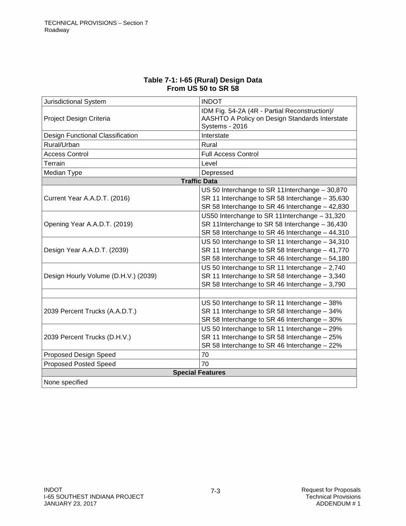
TECHNICAL PROVISIONS – Section 7 Roadway
INDOT Request for Proposals I-65 SOUTHEST INDIANA PROJECT Technical Provisions JANUARY 23, 2017 ADDENDUM # 1
7-3
Table 7-1: I-65 (Rural) Design Data
From US 50 to SR 58 Jurisdictional System INDOT
Project Design Criteria IDM Fig. 54-2A (4R - Partial Reconstruction)/ AASHTO A Policy on Design Standards Interstate Systems - 2016
Design Functional Classification Interstate Rural/Urban Rural Access Control Full Access Control Terrain Level Median Type Depressed
Traffic Data
Current Year A.A.D.T. (2016) US 50 Interchange to SR 11Interchange – 30,870 SR 11 Interchange to SR 58 Interchange – 35,630 SR 58 Interchange to SR 46 Interchange – 42,830
Opening Year A.A.D.T. (2019) US50 Interchange to SR 11Interchange – 31,320 SR 11Interchange to SR 58 Interchange – 36,430 SR 58 Interchange to SR 46 Interchange – 44,310
Design Year A.A.D.T. (2039) US 50 Interchange to SR 11 Interchange – 34,310 SR 11 Interchange to SR 58 Interchange – 41,770 SR 58 Interchange to SR 46 Interchange – 54,180
Design Hourly Volume (D.H.V.) (2039) US 50 Interchange to SR 11 Interchange – 2,740 SR 11 Interchange to SR 58 Interchange – 3,340 SR 58 Interchange to SR 46 Interchange – 3,790
2039 Percent Trucks (A.A.D.T.) US 50 Interchange to SR 11 Interchange – 38% SR 11 Interchange to SR 58 Interchange – 34% SR 58 Interchange to SR 46 Interchange – 30%
2039 Percent Trucks (D.H.V.) US 50 Interchange to SR 11 Interchange – 29% SR 11 Interchange to SR 58 Interchange – 25% SR 58 Interchange to SR 46 Interchange – 22%
Proposed Design Speed 70 Proposed Posted Speed 70
Special Features None specified
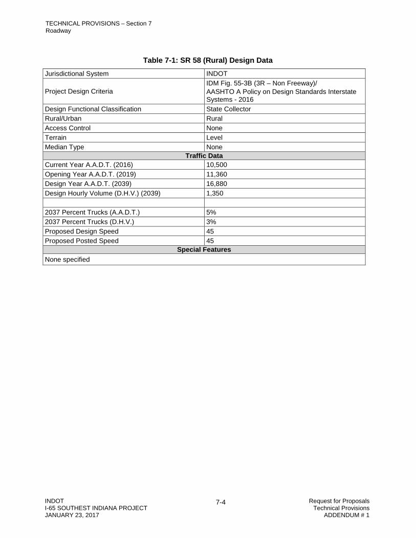
TECHNICAL PROVISIONS – Section 7 Roadway
INDOT Request for Proposals I-65 SOUTHEST INDIANA PROJECT Technical Provisions JANUARY 23, 2017 ADDENDUM # 1
7-4
Table 7-1: SR 58 (Rural) Design Data
Jurisdictional System INDOT
Project Design Criteria IDM Fig. 55-3B (3R – Non Freeway)/ AASHTO A Policy on Design Standards Interstate Systems - 2016
Design Functional Classification State Collector Rural/Urban Rural Access Control None Terrain Level Median Type None
Traffic Data Current Year A.A.D.T. (2016) 10,500 Opening Year A.A.D.T. (2019) 11,360 Design Year A.A.D.T. (2039) 16,880 Design Hourly Volume (D.H.V.) (2039) 1,350 2037 Percent Trucks (A.A.D.T.) 5% 2037 Percent Trucks (D.H.V.) 3% Proposed Design Speed 45 Proposed Posted Speed 45
Special Features None specified

TECHNICAL PROVISIONS – Section 7 Roadway
INDOT Request for Proposals I-65 SOUTHEST INDIANA PROJECT Technical Provisions JANUARY 23, 2017 ADDENDUM # 1
7-5
Interstate-Route Crossovers
Interstate-route crossover locations for I-65 are listed in IDM Figure 54-6B(65). Median crossings included within the Project Limits shall be in accordance with the IDM, except as noted in Table 7-3.
Table 7-3: Interstate Crossovers
Reference Marker I-65 Location Description Action 50.6 1.1 mi. N. of US 50 Reconstruct 54.5 0.7 mi. S. or SR 11 Reconstruct 56.1 0.9 mi. N. of SR 11 Reconstruct 59.5 4.3 mi. N. of SR 11 Reconstruct 63.1` 0.6 mi S. of SR 58 Reconstruct 64.3 0.6 mi. N. of SR 58 Resurface * 66.9 1.3 mi. S. of SR 46 Resurface *
* Location applies if Section E (Added Travel lanes) as defined in Section 1 of the Technical Provisions is selected.
7.3 Design Exceptions Design-Build Contractor may propose Design Exceptions and follow the Department’s Design Exception process; however, INDOT reserves the right to reject, in its sole discretion, any proposed change that requires a Design Exception or does not otherwise conform to the requirements of the PPA Documents. All adjustments to the Project shall conform to applicable Laws and Governmental Approvals. Design-Build Contractor is responsible for time delays in obtaining Design Exceptions. Delays due to approvals for Design Exceptions shall not be considered eligible for a Change Order. All Level Two Design Exceptions shall be approved by INDOT in writing.
INDOT is in the process of obtaining the following Design Exception on this Project:
7.3.1 Level One Design Exceptions
A Level 1 Design Exception is currently under review for approval of an 8 ft paved, 10 ft usable median shoulder on I-65 and is applicable if Section B (Added Travel Lanes) as defined in Section 1 of the Technical Provisions is selected.
7.4 Deliverables Deliverables, a non-exhaustive list of which is set forth in the table below, shall be submitted in electronic format in accordance with the schedule set forth below. Acceptable electronic formats include PDF and current versions of Microsoft Word and Microsoft Excel, unless otherwise indicated.

TECHNICAL PROVISIONS – Section 7 Roadway
INDOT Request for Proposals I-65 SOUTHEST INDIANA PROJECT Technical Provisions JANUARY 23, 2017 ADDENDUM # 1
7-6
Deliverable Schedule TP Section Design Exception documentation As needed 7.3

TECHNICAL PROVISIONS – Section 8 Pavement
INDOT 8-1 Request for Proposals I-65 SOUTHEAST INDIANA PROJECT Technical Provisions JANUARY 23, 2017 ADDENDUM 1
8 PAVEMENT
8.1 General
Design-Build Contractor shall design and construct the pavement Work in accordance with the applicable requirements in the PPA Documents, including Project Standards and this Section 8 and its Attachments 8-1 through 8-5, Governmental Approvals; and applicable Laws.
INDOT’s Authorized Representative will assist in the coordination and resolution of roadway pavement issues with affected interests and regulatory agencies. Design-Build Contractor shall document the resolutions of issues, including meeting minutes and memoranda for the record.
8.2 Design Requirements
Design Build Contractor shall design, analyze, and provide all permanent pavements required. Prepare separate pavement designs for mainline, ramps, and shoulders.
AASHTO PavementME software, version 2.0, shall be used on the Project. Calibration factors for New Flexible and Rehabilitation Flexible subgrade rutting shall be as follows.
𝛽𝛽𝑟𝑟1:0.07 𝛽𝛽𝑟𝑟2:1.9 𝛽𝛽𝑟𝑟3:0.4 𝛽𝛽𝑠𝑠1:0.12 (applies to both “Fine Subgrade Rutting” and “Granular Subgrade Rutting”
Materials for roadway pavement surfaces may be hot-mixed asphalt (HMA) or Portland cement concrete (PCC). The pavement design shall provide for positive drainage of subgrade and subbase materials from under all portions the pavement.
I-65 mainline pavement design shall be designed for two travel lanes in each direction.
I-65 mainline pavement shall be full depth HMA or PCCP except as noted below (RP 53+70 to RP 55+80). The Rubblization of Existing JRCP and Overlay listed in the RID will not be allowed by INDOT as an approved pavement design unless the Rubblization of JRCP is removed and the subgrade is prepared with Subgrade Treatment, Type 1B. The Unbonded PCCP overlay of existing JRCP listed in the RID will not be allowed by INDOT as an approved pavement design. INDOT requires Subgrade Treatment, Type 1B for all I-65 mainline pavements except for the CPR limits as mentioned.
Item No. 1.b. of Section 304-14.02 of the Indiana Design Manual is revised as follows. The use of an open-graded, HMA drainage layer within the HMA pavement’s structure shall not be permitted. The appropriate material properties shall be used for the drainage layer below the HMA pavement. The material must be demonstrated for a permeability value greater to or equal to 2000 ft/day.
Proposed pavement sections shall provide for a drainage layer and separation layer. The separation layer may be aggregate or geotextile as long as the chosen material is shown to not allow the passing of fines.

TECHNICAL PROVISIONS – Section 8 Pavement
INDOT 8-2 Request for Proposals I-65 SOUTHEAST INDIANA PROJECT Technical Provisions JANUARY 23, 2017 ADDENDUM 1
Pavements shall be designed to meet performance criteria referenced in Indiana Design Manual Figure 304-14B. Pavement design life will not be in accordance with Figure 304-14A, but rather as the duration until the combined cumulative Equivalent Single Axle Loads (ESALs) per travel lane provided for functional failure at 79,960,000 for HMA and 97,770,000 for PCC, and for structural failure at 119,950,000 for HMA and 499,350,000 for PCC are met. These ESAL numbers are representative of 90 percent of the direction traffic in the design lane. The combined cumulative ESALs (number of lanes provided x HMA and/or PCCP threshold values shown above) can be distributed among the provided travel lanes. The minimum base pavement design shall provide a total of 599,750,000 ESALs to structural failure for its HMA option and 2,496,750,000 ESALs to structural failure for its PCCP option including the ESALs provided by the new NB inside shoulder being built as a future travel lane-inside shoulder but not including ESALs provided by the new outside full-depth shoulders and the future, SB, build-out travel lane and inside shoulder. The ESALs provided by the base design’s new outside shoulders are in addition to the new pavement and/or shoulders; the new outside shoulders shall be designed for Not Less Than (NLT) 59,975,000 ESALS to structural failure if installed as HMA and 249,675,000 ESALs to structural failure if installed as PCC. The two feet of the new outside shoulders adjacent to the new outside travel lanes shall be constructed with and of the same thickness, mix and material properties of the adjacent travel lane. Not including the new outside shoulder ESALs, the base design provides for functional failure at 239,880,000 for HMA ESALs and 293,310,000 for PCC ESALs, and for structural failure at 358,850,000 HMA ESALs or 1,498,050,000 PCC ESALs NB and for functional failure at 159,920,000 for HMA ESALs and 195,540,000 for PCC ESALs, and for structural failure at 239,000,000 HMA ESALs or 998,700,000 PCC ESALs SB.
ESALs are defined as those calculated by MEPDG. Calculations by other methods or formulas will not be accepted.
The existing composite pavement shall not be used in place. The existing pavement materials can be incorporated into the proposed improvements, but only in an altered state.
The concrete mainline section from RP 53+70 to RP 55+80 shall consist of Concrete Pavement Restoration (CPR) and restoring the smoothness IRI value to 70 or better.
Resurfacing, where required for ramps, will be designed for a functional design life of not less than 13 years, as shown on the output from the PavementME software. Pavement for bridge approaches on state roads and other non-mainline roads shall include a minimum of 1.5 inches of milling and 1.5 inches of QC/QA-HMA, 3, 64, Surface 9.5 mm (165 lbs/ SY).
Subgrade Treatment
Design Build Contractor shall provide subgrade treatment according to Table 8-1 and Project Standards.
Table 8-1 Subgrade Treatment Location Treatment
Jackson County Type IB*
Bartholomew County Type IB
* See Geotech Report for “cement only” recommendations and limits

TECHNICAL PROVISIONS – Section 8 Pavement
INDOT 8-3 Request for Proposals I-65 SOUTHEAST INDIANA PROJECT Technical Provisions JANUARY 23, 2017 ADDENDUM 1
Pavement Design Reports
Design-Build Contractor shall prepare and submit preliminary pavement design reports for all the pavements, permanent temporary, and restoration, required on the project, for review and comment by INDOT. Final pavement design reports shall be signed and sealed by a Registered Professional Engineer and submitted for review and approval by INDOT.
Pavement design reports shall include, at a minimum, the following:
All design inputs, including design method, design life, analysis parameters, performance criteria, traffic load spectra, climate, pavement structural cross section, subgrade and subbase drainage, materials characteristics, and input parameters, including soil subgrade
Design subgrade strength, resilient modulus (Mr) values, planned subgrade improvements, and as-needed subgrade improvements
Discussion of the input parameters, rationale, and assumptions used Site plan showing the limits of the roadway element covered by the report Typical cross-section drawings for the recommended pavement design strategy, including
the overlay of existing pavements Pavement ME input file Summary of total ESALs provided, including separate ESAL values for each lane analyzed
with different traffic distributions.
8.3 Construction
Construction of the permanent pavement shall be according to Project Standards and the following:
Positive drainage along all existing pavement layers shall be maintained. Safety edge shall be provided in accordance with INDOT Design Memorandum 15-02. HMA open-graded drainage layers shall be placed at a minimum thickness of 250 lb/yd²
(2½-inch thickness). Remove all existing inside shoulder pavement prior to construction of widened median
shoulder. Existing shoulders shall be milled and resurfaced with same thickness as the mainline
pavement. Stone Matrix Asphalt (SMA) surface is not required for shoulders. Shoulder corrugation milling is required for all permanent pavements. Shoulder corrugation milling is not required for existing shoulder pavements to remain in place.
Pavement Patching
Attachment 8-5 (Patching Locations) lists the locations for either partial depth and/or full depth patching to be completed prior to any pavement milling.
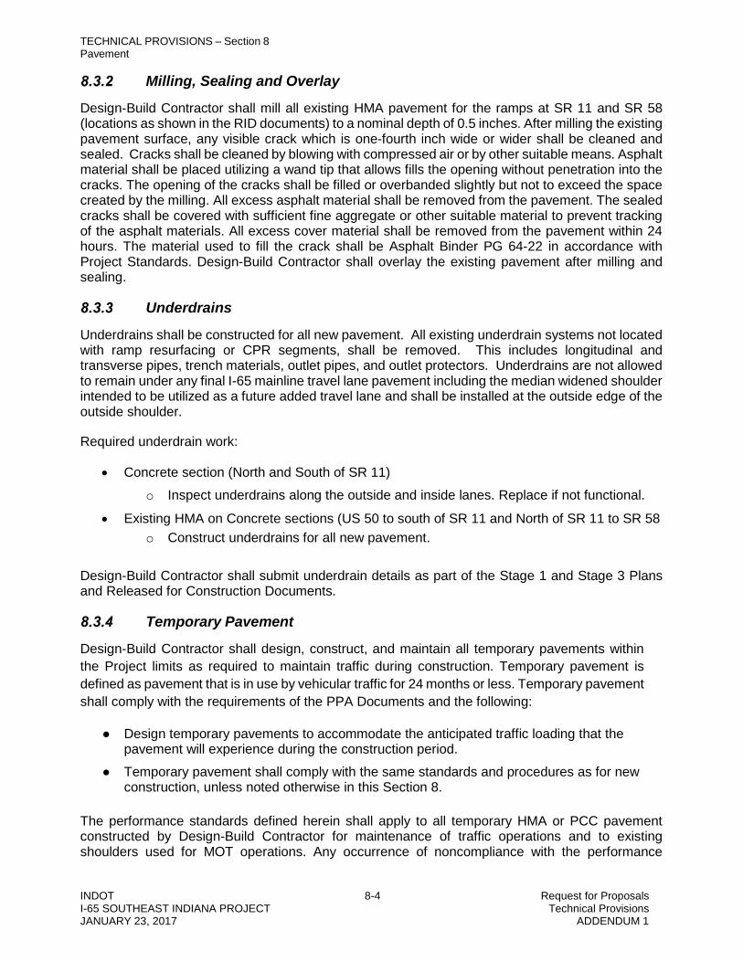
TECHNICAL PROVISIONS – Section 8 Pavement
INDOT 8-4 Request for Proposals I-65 SOUTHEAST INDIANA PROJECT Technical Provisions JANUARY 23, 2017 ADDENDUM 1
Milling, Sealing and Overlay
Design-Build Contractor shall mill all existing HMA pavement for the ramps at SR 11 and SR 58 (locations as shown in the RID documents) to a nominal depth of 0.5 inches. After milling the existing pavement surface, any visible crack which is one-fourth inch wide or wider shall be cleaned and sealed. Cracks shall be cleaned by blowing with compressed air or by other suitable means. Asphalt material shall be placed utilizing a wand tip that allows fills the opening without penetration into the cracks. The opening of the cracks shall be filled or overbanded slightly but not to exceed the space created by the milling. All excess asphalt material shall be removed from the pavement. The sealed cracks shall be covered with sufficient fine aggregate or other suitable material to prevent tracking of the asphalt materials. All excess cover material shall be removed from the pavement within 24 hours. The material used to fill the crack shall be Asphalt Binder PG 64-22 in accordance with Project Standards. Design-Build Contractor shall overlay the existing pavement after milling and sealing.
Underdrains
Underdrains shall be constructed for all new pavement. All existing underdrain systems not located with ramp resurfacing or CPR segments, shall be removed. This includes longitudinal and transverse pipes, trench materials, outlet pipes, and outlet protectors. Underdrains are not allowed to remain under any final I-65 mainline travel lane pavement including the median widened shoulder intended to be utilized as a future added travel lane and shall be installed at the outside edge of the outside shoulder.
Required underdrain work:
• Concrete section (North and South of SR 11) o Inspect underdrains along the outside and inside lanes. Replace if not functional.
• Existing HMA on Concrete sections (US 50 to south of SR 11 and North of SR 11 to SR 58 o Construct underdrains for all new pavement.
Design-Build Contractor shall submit underdrain details as part of the Stage 1 and Stage 3 Plans and Released for Construction Documents.
Temporary Pavement
Design-Build Contractor shall design, construct, and maintain all temporary pavements within the Project limits as required to maintain traffic during construction. Temporary pavement is defined as pavement that is in use by vehicular traffic for 24 months or less. Temporary pavement shall comply with the requirements of the PPA Documents and the following:
Design temporary pavements to accommodate the anticipated traffic loading that the pavement will experience during the construction period.
Temporary pavement shall comply with the same standards and procedures as for new construction, unless noted otherwise in this Section 8.
The performance standards defined herein shall apply to all temporary HMA or PCC pavement constructed by Design-Build Contractor for maintenance of traffic operations and to existing shoulders used for MOT operations. Any occurrence of noncompliance with the performance

TECHNICAL PROVISIONS – Section 8 Pavement
INDOT 8-5 Request for Proposals I-65 SOUTHEAST INDIANA PROJECT Technical Provisions JANUARY 23, 2017 ADDENDUM 1
standards shall be corrected as soon as possible but no longer than 24 hours after noncompliance is reported in writing by INDOT to Design-Build Contractor. Any areas not meeting these performance requirements are subject to liquidated damages per PPA Exhibit 10.
Temporary pavement shall meet the following requirements:
Minimum friction number of 37 IRI of less than 120 inches/mile Free of potholes, fatigue areas, duress, and rutting exceeding 0.25 inches Provide adequate cross slope to drain water quickly from pavement surface
Pavement distresses are identified in Federal Highway Administration publication FHWA-RD-03-031.
Construct MOT pavements according to the applicable Project Standards.
Design-Build Contractor shall provide all traffic control, templates, straight edges and measuring devices required by INDOT to monitor compliance with requirements of this section.
If INDOT believes, in its sole discretion, that these requirements are not being met, INDOT will direct Design-Build Contractor to conduct pavement testing to measure the pavement properties. Both the testing and corrective actions shall be considered part of Design-Build Contractor’s Work.
8.3.4.1 Temporary HMA Pavement Performance Standards
Construct and maintain temporary HMA pavements for MOT according to Project Standards and the following:
1. No occurrence of pavement shoving shall exceed 2.0 square feet in area at any location. 2. No occurrence of pavement rutting shall exceed 0.4 inches in depth for surface pavement,
and no occurrence of pavement rutting shall exceed 0.5 inches in depth for surface pavement and subgrade combined. Further, the average pavement rutting for any continuous 300-foot length of pavement shall not exceed 0.25 inches in depth, as determined by averaging the rut measurements at five locations spaced at least 50 feet apart but not more than 60 feet apart.
3. No edge drop-off shall exceed 0.5 inches in depth for a continuous length of 15 feet or more. 4. No depression exceeding 0.5 inches in depth (e.g., pothole) shall exceed 0.5 square feet in
area. 5. No bump exceeding 0.5 inches in height shall exceed 0.5 square feet in area. 6. No location of delamination or raveling shall exceed 0.5 square feet in area. Furthermore,
the total delamination or raveling shall not exceed 3.0 square feet for all such locations. 7. There shall be no occurrences of fatigue cracking at any location on the MOT pavement.
8.3.4.2 Temporary PCC Pavement Performance Standards
Construct and maintain temporary PCC pavement according to Project Standards and the following:

TECHNICAL PROVISIONS – Section 8 Pavement
INDOT 8-6 Request for Proposals I-65 SOUTHEAST INDIANA PROJECT Technical Provisions JANUARY 23, 2017 ADDENDUM 1
1. There shall be no occurrences of faulting (0 inch) at any location on the MOT pavement. 2. No pavement crack (transverse, longitudinal or otherwise) on the MOT pavement shall
exceed 0.125 inches in width. 3. There shall be no use of roller-compacted concrete as MOT pavement.
8.3.4.3 Existing HMA Shoulder Performance
If the existing shoulder pavement is to be used as MOT pavement, comply with the following requirements:
1. Mill the shoulder used for MOT including any existing shoulder corrugations, and the portion of the shoulder used for MOT shall be resurfaced prior to MOT operations.
2. No occurrence of pavement shoving shall exceed 2.0 square feet in area at any location. 3. No occurrence of pavement rutting shall exceed 0.4 inches in depth for surface pavement,
and no occurrence of pavement rutting shall exceed 0.5 inches in depth for surface pavement and subgrade combined Further, the average pavement rutting for any continuous 300-foot length of pavement shall not exceed 0.25 inches in depth, as determined by averaging the rut measurements at five locations spaced at least 50 feet apart but not more than 60 feet apart.
4. No edge drop-off shall exceed 0.5 inches in depth for a continuous length of 15 feet or more. 5. No depression exceeding 0.5 inches in depth (e.g., pothole) shall exceed 0.5 square feet in
area. 6. No bump exceeding 0.5 inches in height shall exceed 0.5 square feet in area. 7. No location of delamination or raveling shall exceed 0.5 square feet in area. Furthermore,
the total delamination or raveling shall not exceed 3.0 square feet for all such locations. 8. There shall be no occurrences of fatigue cracking at any location on the MOT pavement.
8.4 Certification
All field and laboratory testing for pavements and associated materials conducted by Design-Build Contractor shall be conducted in an accredited laboratory and performed by certified personnel who are qualified to perform INDOT test methods.
8.5 Deliverables
Deliverables, a non-exhaustive list of which is set forth in the table below, shall be submitted in electronic format in accordance with the schedule set forth below. Acceptable electronic formats include PDF and current versions of Microsoft Word and Microsoft Excel, unless otherwise indicated.
Deliverable Schedule TP Section Preliminary pavement design report With Stage 1 Plans 8.2.2 Final pavement design report Prior to Released for Construction Documents 8.2.2 Underdrain details With Stage 1 and Stage 3 Plans 8.3.3

TECHNICAL PROVISIONS – Section 9 Drainage
INDOT 9-1 Request for Proposals I-65 SOUTHEAST INDIANA PROJECT Technical Provisions JANUARY 23, 2016 ADDENDUM # 1
9 DRAINAGE
9.1 9.1 General Design-Build Contractor shall design and construct the drainage Work in accordance with the applicable requirements in the Indiana Design Manual, PPA Documents, including Project Standards, this Section 9 and its Attachment 9-1 (Unique Special Provisions: Drainage), and Attachment 9-3 (Pipe Ratings); Governmental Approvals; and applicable laws.
9.2 Culverts Replacement Determination
Replace or line existing culverts based on the structural determination from Attachment 9-3 (Pipe Ratings) and the criteria below. Requirements for culverts (with exception of identified previously lined pipe) are as follows:
1. Unlined Culverts a. Barrel Rating less than 5, culvert shall be replaced. b. Barrel Rating equal to or greater than 5 and less than 9, culvert may be lined
provided that the lined culvert meets hydraulic requirements. IF lining the culvert does not meet hydraulic requirements, the culvert shall be replaced or other improvements to meet hydraulic requirements shall be implemented.
c. Barrel Rating equal to or greater than 9 may remain in place if the culvert and any required extension meet hydraulic requirements. If the culvert does not meet hydraulic requirements, the culvert shall be replaced or other improvements to meet hydraulic requirements shall be implemented.
d. Replace all existing pipe culverts that do not meet the minimum size as defined in IDM Figure 203-2B.
2. Lined Culvert a. Barrel Rating less than 5, culvert shall be replaced. b. Barrel Rating equal to or greater than 5, culvert may remain in place.
Culvert Lining
Line all Culverts that are larger than or equal to 36-inch diameter (or hydraulic equivalent) and less than 48-inch diameter (or hydraulic equivalent).
Hydraulic Capacity Evaluation Evaluate hydraulic parameters for all culverts within the project limits. Evaluate all lined culverts for both the pre-lined and lined conditions. Proposed hydraulic parameters shall be in accordance with Indiana Design Manual. Submit hydraulic reports for all culvert replacements and liner, storm sewers and detention to INDOT for approval. Obtain approval from INDOT prior to construction.
TECHNICAL PROVISIONS – Section 9 Drainage
INDOT 9-2 Request for Proposals I-65 SOUTHEAST INDIANA PROJECT Technical Provisions JANUARY 23, 2016 ADDENDUM # 1
9.3 Technical Requirements Erosion protection measures shall be installed at the outlet of new and improved drainage
structures. Outlet velocities shall be restricted to 1.5 times the natural stream velocity or 6.5 ft/s, whichever is greater when it leaves INDOT’s right-of-way. Internal dissipaters will not be allowed. External dissipaters shall be constructed within existing INDOT right-of-way.
Where undercutting is present at the inlet of an existing culvert, appropriate measures shall be installed to prevent continued undercutting.
New storm sewer drain shall discharge a minimum of 12 inches above the ditch flowline elevation unless an approved hydraulic analysis indicates a 6 inch minimum eliminates adverse impacts on the hydraulic grade line requirements.
Underdrains shall be designed and installed along all roadways. Underdrain design shall be in accordance with the Indiana Design Manual. Underdrains runs shall be extended with cleanout ports installed at a maximum spacing of 600 feet until the required freeboard can be met.
Existing field tile drainage shall be maintained at all times. Any field tiles disturbed by the Design-Build Contractor shall be replaced.
All existing drainage structures that will not be used in the final drainage system shall either be removed and backfilled with structure backfill, Type 5 or be filled with structure backfill, Type 5.
Existing cross culverts are tabulated in the Reference Information Documents. These culverts shall be evaluated for hydraulic parameters.
Where a supplemental pipe is necessary for conveyance adjacent to a lined culvert, the minimum diameter of the supplemental pipe shall be 18 inches. Supplemental pipes shall be installed with the invert located a minimum of 6 inches above the lined invert.
Inlet spacing, storm drain capacity, and slotted drain computations shall be performed by the Design-Build Contractor. Slotted drain is required on high side, superelevated shoulder that is sloped toward the travel lanes where guardrail, barrier or rail prevents snow removal from the shoulder.
Median ditches, median inlet spacing, and median drain capacity computations shall be performed by the Design-Build Contractor for the 2% annual exceedance probability, EP, storm. The hydraulic grade line shall not encroach onto the travel lanes. All existing metal median drain pipes shall be replaced or lined if a liner can meet the hydraulic requirements. Additional median drain pipes and inlets shall be added as required to meet hydraulic requirements.
No stormwater detention storage is allowed in median ditches. For cast-in-place pipe lining, follow the requirements of Attachment 9-1 (Unique Special
Provisions: Drainage). Water quantity control shall be designed by the Design-Build contractor so that wherever
stormwater is leaving the project site, the post development peak runoff shall not exceed the pre-development peak runoff at the point of discharge from the right-of-way.
The design pool level elevation for a detention basin outside the roadway shall not encroach on the clear zone if the depth is 2 ft or greater, unless it is protected with guardrail.
TECHNICAL PROVISIONS – Section 9 Drainage
INDOT 9-3 Request for Proposals I-65 SOUTHEAST INDIANA PROJECT Technical Provisions JANUARY 23, 2016 ADDENDUM # 1
The Design-Build Contractor shall notify the Jackson County surveyor of any Work impacting regulated drains in Jackson County prior to commencement of any construction activity. Detention design computations (as described in Section 9.3 Item 13 and associated plans shall be submitted to: Jackson County Surveyor’s Office
The Design-Build Contractor shall notify the Bartholomew County surveyor of any Work impacting regulated drains in Bartholomew County prior to commencement of any construction activity. Detention design computations (as described in Section 9.3 Item 13) and associated plans shall be submitted to: Bartholomew County Surveyor’s Office
Type P inlets are to be used inside the clear zone for median ditch drainage. A clogging factor of 50% shall be used in the hydraulic calculations for all drainage
structures which do not have a curb box except for the type P inlets. The type P inlets do not require a clogging factor. Flanking inlets are required at all sag points where water ponded at a clogged inlet cannot overflow to another location with adequate capacity to receive the flow without exceeding the allowable spread.
For any detention pond constructed in the vicinity of a stream, the pond shall be located a sufficient distance from the stream to maintain a 15-foot-wide cleared area beyond the toe of any berms surrounding the pond, plus an additional 30-foot-wide, or larger, vegetated buffer along the stream.
9.4 Culvert Work within Bartholomew County Right of Way The following culvert may require work within existing Bartholomew County right-of-way.
The Design-Build Contractor shall separate the existing 72-in CMP located at approximate RP 57+0.1 (west of I-65) into two distinct structures so the portion on INDOT right-of-way does not extend onto County right-of-way. If field conditions require removal of additional pipe within County right-of-way beyond the minimum length to perpetuate the existing access road, the Design-Build Contractor shall extend the existing pipe.
The Design-Build Contractor shall separate the existing 60-in by 45-in CMPA located at approximate RP 57+0.64 (west of I-65) into two distinct structures so the portion on INDOT right-of-way does not extend onto County right-of-way. If field conditions require removal of additional pipe within County right-of-way beyond the minimum length to perpetuate the existing access road, the Design-Build Contractor shall extend the existing pipe.
The Design-Build Contractor shall perpetuate the existing 66-in CMP length at RP 58+0.52 (east of I-65). Culvert lining or replacement shall be one continuous structure.
The Design-Build Contractor shall separate the existing 36-in CMP at RP 62+0.1(east of I-65) from all other pipes currently connected through a field junction within INDOT right-of-way.

TECHNICAL PROVISIONS – Section 9 Drainage
INDOT 9-4 Request for Proposals I-65 SOUTHEAST INDIANA PROJECT Technical Provisions JANUARY 23, 2016 ADDENDUM # 1
9.5 Deliverables Deliverables, a non-exhaustive list of which is set forth in the table below, shall be submitted in both hardcopy and electronic format in accordance with the schedule set forth below. Acceptable electronic formats include PDF and current versions of Microsoft Word and Microsoft Excel, unless otherwise indicated.
Deliverable Submittal Schedule TP Section CIPP field-cured sample report Within 7 days of receipt Attachment 9-1 Hydraulic capacity evaluation report Prior to construction 9.2.3
Detention evaluation report Prior to construction 9.3 Storm Sewer report Prior to construction 9.3
TECHNICAL PROVISIONS – Section 10 Traffic
INDOT 10-1 Request for Proposals I-65 SOUTHEAST INDIANA PROJECT Technical Provisions JANUARY 23, 2017 ADDENDUM # 1
10 TRAFFIC
General
Design-Build Contractor shall design and construct the pavement markings, signing, and lighting Work in accordance with the applicable requirements in the PPA Documents, including Project Standards, this Section 10 and its Attachment 10-1 (Unique Special Provisions: Traffic); Governmental Approvals; and applicable laws.
Technical Requirements
Pavement Markings
Durable pavement markings shall be used for longitudinal pavement markings. This includes edge lines, lane lines, dotted lines, broken lines, and longitudinal gore lines. Design and installation of high durability pavement markings shall be as set forth in INDOT Design Memorandum 15-19.
New snow-plowable raised pavement markers (RPMs) shall be designed and installed along I-65 mainline and all interchange ramps where existing RPMs are disturbed or do not currently exist, in accordance with the Indiana Design Manual and Standard Drawings. RPMs shall not be installed on bridge decks.
Signing
Design-Build Contractor shall develop the signing plans in accordance with the Indiana Design Manual, Design Memo 15-03 and Indiana MUTCD.
Design-Build Contractor shall replace all existing regulatory, warning, and guide panel and sheet signs within Section A (Project Limits - I-65 from US 50 to SR 58) as defined in Section 1 of the Technical Provisions. Sign supports that are impacted by the Work may be reset on new foundations if they meet current standards.
1. The appropriate standard highway font shall be used for all signs. All signs along the mainline freeway and associated ramps shall be “freeway” size.
2. Design-Build Contractor shall use INDOT standard sign structures and foundations where possible. All required special sign structures shall be designed per IDM Section 502-1.01(11) and 502-1.01(12).
3. Existing reference marker signs shall be replaced and shall be placed every 0.5 miles within the project limits for both the northbound and southbound directions of I-65 mainline.
4. Design-Build Contractor shall coordinate with Indiana Business Logo for all existing Logo signs, in accordance with Attachment 10-1 (Unique Special Provisions: Traffic).
5. No signs or sign structures shall be mounted on the bridge overpass structures. Existing signs mounted on bridge overpass structures shall be removed.
6. No signs shall be banded/installed to utility poles, lighting poles, or overhead or cantilever sign structure uprights.
7. Sign lighting for newly installed panel signs is not required.

TECHNICAL PROVISIONS – Section 10 Traffic
INDOT 10-2 Request for Proposals I-65 SOUTHEAST INDIANA PROJECT Technical Provisions JANUARY 23, 2017 ADDENDUM # 1
8. All existing signage shall be evaluated for relevance. If a sign is determined to be no longer relevant, it shall be removed or replaced, as appropriate.
9. Where three travel lanes are open to traffic, the inside travel lane shall include signage prohibiting trucks in left lane. This requirement applies if Section B (Added Travel lanes) as defined in Section 1 of the Technical Provisions is selected.
Lighting
Design Builder Contractor shall replace all non–LED conventional and high mast luminaires with approved LED luminaires within Section A (Project Limits - I-65 from US 50 to SR 58) as defined in Section 1 of the Technical Provisions.
Design Builder shall remove all existing lighting from overhead sign structures including the lighting supports and all other appurtenances to the service point.
Design-Build Contractor shall design and install lighting per the Indiana Design Manual where Work impacts existing lighting or other modifications are necessary to meet the requirements of the Technical Provisions.
Design-Build Contractor shall coordinate the heights of new or relocated high-mast structures with INDOT and the FAA to comply with FAA requirements. Design-Build Contractor shall apply for and obtain permits as necessary.
All existing light structures, such as high-mast towers and conventional light poles that require relocation or replacement shall be removed with no outages. Design-Build Contractor shall maintain proper illumination levels at all times.
All existing light poles that are replaced and not relocated shall be salvaged and delivered to the INDOT Seymour Maintenance Unit, 185 Agrico Lane, Seymour, IN.
Traffic Signals
The Design-Build Contractor shall be responsible for designing and constructing traffic signals at SR 58 and International Drive and the two I-65 Ramps at SR 58. A minimum intersection Level of Service (LOS) C shall be provided in the design year. Right turn lanes will be required at both I-65 entrance ramps (from SR 58 to I-65).
The Design Builder shall modernize the existing flasher at SR 250 and US 31 to a traffic signal. Upon completion of the construction on I-65, the Design Builder shall return the traffic signal to a flasher.
All signals shall be equipped with an Aries Field Processor and cellular connection to the TMC.
All traffic signals shall be installed prior to construction activities along I-65.
Traffic signal equipment shall comply with INDOT Standard Specifications.
Traffic signal heads shall be LED.
The Design-Build Contractor shall provide an approved radio signal interconnection between signals located at Industrial Drive, I-65 SB terminal, I-65 NB terminal and Old Lane Drive.

TECHNICAL PROVISIONS – Section 10 Traffic
INDOT 10-3 Request for Proposals I-65 SOUTHEAST INDIANA PROJECT Technical Provisions JANUARY 23, 2017 ADDENDUM # 1
The Design-Build Contractor shall supply a working drawing for any non-standard signal pole foundation design certified by a Registered Indiana Professional Engineer.
The Design-Build Contractor shall conduct a meeting with the District Traffic Engineer within 3 weeks of award of contract. The District Traffic Engineer is:
Hillary Lowther INDOT Seymour District 185 Agrico Lane Seymour, IN 47274 812-524-3711 [email protected]
Deliverables
Not used.

TECHNICAL PROVISIONS – Section 11 Maintenance of Traffic (MOT)
INDOT 11-1 Request for Proposals I-65 SOUTHEAST INDIANA PROJECT Technical Provisions JANUARY 23, 2017 ADDENDUM # 1
11 MAINTENANCE OF TRAFFIC, HAUL ROUTES AND ACCESS
General
Maintenance of Traffic (MOT) shall be performed in a manner that minimizes construction, rehabilitation, maintenance duration, and impact to the traveling public. This Section 11 defines specific requirements, restrictions, and allowable closure durations for both travel lanes and ramps.
Design-Build Contractor shall design and construct the MOT, haul routes, and access in accordance with the applicable requirements of the PPA Documents, including Project Standards, this Section 11 and its Attachment 11-1 (Unique Special Provisions: Maintenance of Traffic); Governmental Approvals; and applicable laws.
Performance Requirements
Project-Wide Transportation Management Plan
Design-Build Contractor shall prepare, implement, and maintain a Transportation Management Plan (TMP) in accordance the Indiana Design Manual, Chapter 81. The TMP shall include a Traffic Operations Plan (TOP), a Temporary Traffic Control Plan (TTCP), and a coordination process with the Public Involvement Plan (PIP), described in Section 5 (Public Involvement), and must be approved before initiation of any Construction Work. INDOT will provide Design-Build Contractor with a list of INDOT representatives for the Project traffic management team to be included in Design-Build Contractor’s TMP. The TMP shall be developed in coordination with, and include procedures to communicate, all MOT phase installations and changes with emergency service providers, school transportation officials, and all affected local public agencies.
The TMP shall be developed in coordination with and be consistent with the PIP and include procedures to communicate TMP information to the Public Information Coordinator for communication of all MOT work to the public prior to implementation of any MOT phase or phase change.
The Traffic Operations Plan (TOP) shall include:
1. Design-Build Contractor identification of an MOT Manager to coordinate all construction traffic impacts with INDOT’s PIP Manager and TMP team, and with Design-Build Contractor’s Certified Worksite Traffic Supervisor (CWTS), who is responsible to monitor daily MOT activities.
2. Descriptions of contact methods and response times of the CWTS to address any conditions needing attention during all hours.
3. Coordination with the Emergency Plan, including identification of staging areas where equipment or vehicles needed for incident clearance response can be stored and have reasonable and safe access to the construction zones. Design-Build Contractor shall have the necessary equipment on-Site to repair temporary barrier and/or to set up temporary traffic control until the barrier can be repaired.
4. Procedures to identify and incorporate the needs of transit operators, Utility Owners, and business owners in the Project corridor, including Utility Owner access and business access signing.

TECHNICAL PROVISIONS – Section 11 Maintenance of Traffic (MOT)
INDOT 11-2 Request for Proposals I-65 SOUTHEAST INDIANA PROJECT Technical Provisions JANUARY 23, 2017 ADDENDUM # 1
5. Identification of measurable limits for the repair and replacement of traffic control devices, including pavement markings, as called out in the Standard Specifications.
6. A process to identify, design, and receive approval for all necessary temporary traffic signals.
7. A process to determine the need for revised traffic signal timings, and if revisions are required, detailed procedures for the development, approval, implementation, testing, and maintenance of all affected signals.
8. A work zone access management map and a construction haul route map for each construction phase.
9. Methods and frequency of inspection and maintenance of all traffic control throughout the Project limits.
10. Provisions to provide continuous access to established truck routes and any hazardous material routes.
11. Procedures for modification of the MOT Plans as needed to adapt to current Project circumstances.
Temporary Traffic Control Plan
Design-Build Contractor shall prepare, submit, and implement a Temporary Traffic Control Plan (TTCP). Approved TTCP shall be included with each applicable RFC package. TTCP shall become part of the appropriate TMP as amendments once the TTCP is approved by INDOT.
The TTCP defines how Design-Build Contractor is to phase construction and detail all the required elements of the physical work zone. The TTCP for the Project includes queuing/delay analysis. No queuing analysis for a given travel direction is needed if two lanes of travel are maintained. Upon completion of queuing/delay analysis, MOT Plans and MOT Special Provisions shall be developed and included with the RFC Design Documents. The MOT Plans shall include all major traffic shifts, lane closures, use of temporary roadways, temporary traffic signals, and access modifications to businesses and residences. The anticipated duration of each phase shall also be noted on the plan.
In addition to the requirements in the IDM, the TTCP shall include the following information:
1. A cover page/title sheet sealed by a Registered Professional Engineer. 2. Standard Drawings 3. MOT Plans, with a traffic and mobility analysis performed for each phase of construction.
Refer to Section 11.2.4 for analysis requirements. The MOT Plans shall detail phases and durations and shall identify all long-term lane closures and lane restrictions anticipated during the Work.
4. Descriptions of the design methods to be used for temporary roadways. 5. Detour and haul routes required for the purpose of Construction Work. Design-Build
Contractor shall obtain approval from local agencies for all proposed detour and haul routes and shall obtain, pay for, and comply with requirements of all necessary Governmental Approvals and agreements required for said routes.
6. Special Provisions that include a switching procedure between each controlled MOT phase change. The switching procedure shall consist of the methods, actions, and

TECHNICAL PROVISIONS – Section 11 Maintenance of Traffic (MOT)
INDOT 11-3 Request for Proposals I-65 SOUTHEAST INDIANA PROJECT Technical Provisions JANUARY 23, 2017 ADDENDUM # 1
signing necessary to complete the switch and the number and duties of traffic personnel assigned to perform the switch.
7. Special Provisions that describe a process for transitioning from temporary signage and temporary pavement marking to permanent signing and permanent pavement marking.
8. Special Provisions that specify Design-Build Contractor coordination work with the construction and maintenance projects of Governmental Entities that are adjacent to or near the Project ROW. The Special Provisions shall include a coordination clause listing other adjacent or nearby construction projects. At a minimum, this shall include the projects listed in Section 1 (General Scope of Work).
9. Special Provisions that require Design-Build Contractor to maintain existing access to all properties within the Project limits for the duration of the Construction Work, except as provided elsewhere in the PPA Documents. Appropriate information about access modifications shall be made available to the property owners as required in the PIP.
10. All information required in Section 11.3.10. The MOT Plans shall be prepared at an appropriate scale to facilitate INDOT review, according to the IDM and include the following components for each phase of construction:
1. Plan insert sheets, including ingress/egress locations for Design-Build Contractor-Related Entities
2. Haul routes
Approved Analysis Techniques and Software for the TMP
Until Substantial Completion, the criteria used to determine the impact of proposed work zones shall be queue length and minimum delay times. Design-Build Contractor shall utilize the approved queue analysis tools in accordance with the INDOT Interstate Congestion Policy to model the expected queue lengths and delay times that will be generated.
Work Zone Mobility Impact Analysis
Using no-build traffic data or, if not available, existing traffic counts supplemented by additional traffic counts by Design-Build Contractor, and analysis techniques described in Section 11.2.3, Design-Build Contractor shall test all MOT phases proposed on the Project to ensure compliance with Project Standards. The traffic alternative analysis shall be submitted to INDOT Seymour District Traffic Engineer Hillary Lowther, (812) 524-3711, with the MOT Plans and be subject to the same review requirements. The traffic analysis shall be summarized in report format, and all supporting documentation shall also be submitted to INDOT. The requirements of this Section 11.2.4 apply through Substantial Completion.
The following thresholds for mainline and arterials shall be used by Design-Build Contractor in the evaluation of the work zone mobility impacts:
11.2.4.1 I-65 and Ramps
Design-Build Contractor shall maintain two lanes in each direction on mainline I-65 at all times during construction except as described in Section 11.3.10. Design-Build Contractor shall evaluate work zone mobility impacts associated with each MOT phase to ensure compliance with the INDOT Interstate Highways Congestion Policy.

TECHNICAL PROVISIONS – Section 11 Maintenance of Traffic (MOT)
INDOT 11-4 Request for Proposals I-65 SOUTHEAST INDIANA PROJECT Technical Provisions JANUARY 23, 2017 ADDENDUM # 1
Ramps shall be evaluated as arterial roadways, except areas at ramp terminals, where Sections 11.2.4.2 or 11.2.4.3 apply. No queue from any ramp shall back up onto I-65 as a result of MOT phasing.
11.2.4.2 Unsignalized Intersections
If the LOS on each approach under stop or yield control is between A and C, then the LOS during MOT operations on each approach shall not be reduced below a D with an average control delay per vehicle of up to 30 s/veh. If the 30 s/veh control delay is exceeded, alternative strategies shall be submitted to INDOT for approval. If the existing LOS on each approach is D or worse, then the control delay during MOT operations on each approach shall not increase more than 30 percent. If the 30 percent threshold is exceeded, alternative strategies shall be submitted to INDOT for approval. Traffic analysis shall not assume more than 25% volume diversion due to drivers avoiding the work zone.
11.2.4.3 Local and other State Route Arterial Roadway Segments
If flagging operations are performed on a local or other state route arterial roadway segment, maximum delay shall be no greater than 10 minutes for any vehicle. In addition, maximum queue lengths as described in the IDM shall not be exceeded. At signalized intersections, an LOS on each approach shall be maintained at or above an LOS D with a control delay of up to 45 seconds.
If specific work activities and time periods preclude compliance with the threshold levels listed in this Section 11.2.4, Design-Build Contractor shall submit a request for Deviation to INDOT for approval in accordance with Section 13 of the PPA. All Deviations from the threshold levels shall be submitted as early in the design process as possible. The request for Deviations from the threshold levels shall include the following:
1. Description: a. Specific location and work required b. Existing condition c. Purpose for the threshold exception request, along with how long and what hours the
lane closures will be in effect d. Recommendations to minimize impacts
2. MOT Alternatives – All potential options for MOT with descriptions and discussions of
each, including the following: a. Advantages/disadvantages b. Estimated time frame c. User and construction cost d. Potential economic impact to communities and businesses e. Ability to gain public buy-in and awareness of the impacts and means to mitigate
those impacts
3. Traffic Analysis: a. Queue/delay analysis

TECHNICAL PROVISIONS – Section 11 Maintenance of Traffic (MOT)
INDOT 11-5 Request for Proposals I-65 SOUTHEAST INDIANA PROJECT Technical Provisions JANUARY 23, 2017 ADDENDUM # 1
b. Percent diversion that is reasonable to expect for the location and conditions c. Queues with expected percentage of traffic diverting
4. Summary and Recommendations:
a. List alternatives in order of preference and explain why the alternative is or is not preferred.
b. Summarize alternatives in table format, including important comparison items such as maximum queue lengths, the number and width of open lanes, the length, dates and duration of construction period, incremental construction cost associated with each option, etc.
Design-Build Contractor shall monitor queues and delays during MOT operations. If the thresholds listed in Section 11.2.4 are being exceeded, Design-Build Contractor shall modify the MOT Plans to mitigate the queues and keep delays below the threshold levels. All proposed changes to the MOT Plans shall be submitted to INDOT for review and comment.
Design and Construction Requirements
Design Criteria
The information listed below shall be incorporated into the MOT Plans and the TMP.
1. Design Speed a. The design speed and posted speed on state highways shall be the existing posted
speed limit on approaches to the work zone, with a maximum 10-mile-per-hour speed reduction within the work zone; all worksite speed limit signs must conform to the provisions found in INDOT Construction memo 14-06.
b. The design speed on non-state highway facilities shall be the existing posted speed limit on approaches to the work zone, with a maximum 10-mile-per-hour reduction of posted speed within the work zone. The posted speed can be reduced an additional 10 miles per hour in the work zone using flashing worksite speed limit assemblies as shown in the Department Standard Drawings with “When Workers Are Present” signing.
2. Lane Widths. The minimum MOT lane width shall be 11 feet on Interstate, Ramps, State,
city, and county routes. 3. Paved Shoulder Widths. All pavement edges shall be a minimum of 2 feet away from the
edge of a travel lane. 4. Separation
a. Temporary concrete barrier and approved end treatments shall be used to protect the motoring public from the work area within the Project limits when work or equipment, including personal vehicles and trucks used for loading and unloading, are within an 8-foot offset of the travel lane. Portable concrete barrier or temporary guardrail shall be provided if the entire clear zone is not traversable or if hazards exist within the clear zone.
b. Portable concrete barrier on bridge decks shall be anchored per the manufacturers’ recommendation.

TECHNICAL PROVISIONS – Section 11 Maintenance of Traffic (MOT)
INDOT 11-6 Request for Proposals I-65 SOUTHEAST INDIANA PROJECT Technical Provisions JANUARY 23, 2017 ADDENDUM # 1
c. On State highways, tubular delineators shall be used between opposite bounds to separate two-way traffic when opposing traffic is maintained on the same roadbed, in accordance the Department Standard Drawings.
5. A construction zone energy absorbing terminal shall be provided at the ends of all temporary traffic barrier exposed to traffic.
6. Acceleration and deceleration lanes shall be provided at all I-65 entrance and exit ramps that are open to traffic.
7. Crash Compliance. All work zone traffic control devices shall be compliant AASHTO Manual for Assessing Safety Hardware (MASH).
8. Signing/Lane Shifts/Closures. All MOT procedures shall be in accordance with the MUTCD.
9. Overhead construction warning signs shall be provided upstream and downstream of work over any navigable waterway.
10. Pavement Edge Drop-Offs a. Drop-off conditions 3 inches or less shall be delineated by barrels, vertical panels, or
tubular markers spaced every 40 feet or a distance in feet equivalent to two times the speed limit in miles per hour, whichever is less.
b. Drop-offs greater than 3 inches shall comply with the following restrictions: 1) When drop-off is a result of excavations adjacent to traffic with a horizontal
separation of 0 to 3 feet, the drop-off shall be limited to 500 feet in continuous length per location unless positive protection is provided before excavation commences. Locations of drop-offs shall be separated by at least 1.0 mile.
2) Shall be wedged with dense graded aggregate or HMA on a 3:1 (H:V) or flatter slope if horizontal separation is less than 8 feet between traffic and the drop-off and no positive protection is provided. If a horizontal separation of 8 feet or greater can be achieved between traffic and the drop-off, no wedging is required. Design-Build Contractor shall provide the wedge prior to the stoppage of work at that location.
3) Shall be delineated by barrels spaced every 40 feet or at an interval in feet equivalent to two times the speed limit in miles per hour, whichever is less.
c. Temporary drop-offs during working hours in which construction operations are taking place shall be kept to a minimum, and are restricted to off-peak hours.
11. Channelizing Devices
a. Channelizing devices approved for use are detailed in the Project Standards. Design-Build Contractor shall comply with INDOT Standard Drawings and Standard Specifications regarding the utilization of drums or other channelizing devices for traffic control.
b. Temporary channelizing device spacing in tapers shall be a maximum of 40 feet center-to-center or a distance in feet equivalent to the speed limit in miles per hour, whichever is less. Device spacing in tangent sections of mainline and ramps (including curves) shall be a maximum of 80 feet center-to-center or a distance in feet equivalent to two times the speed limit in miles per hour, whichever is less. On local roadways, device spacing shall be a maximum of 20 feet center-to-center in

TECHNICAL PROVISIONS – Section 11 Maintenance of Traffic (MOT)
INDOT 11-7 Request for Proposals I-65 SOUTHEAST INDIANA PROJECT Technical Provisions JANUARY 23, 2017 ADDENDUM # 1
tapers, 40 feet center-to center in tangent sections, and 6 feet center-to-center in radii.
c. Design-Build Contractor shall provide, erect, and maintain channelizing devices, signs, barriers, and other traffic control devices used for MOT in acceptable condition, in accordance with the Project Standards.
12. Flashing Arrows and Variable Message Boards. Design-Build Contractor shall supply all
flashing arrows and variable message boards necessary to maintain traffic. Upon completion of the Project, the flashing arrows and variable message boards shall remain the property of Design-Build Contractor.
13. Drainage shall be maintained at all times during all phases of Construction Work. 14. Traffic signals, either temporary or permanent, shall remain operational from beginning
of implementation to end of implementation. 15. Temporary crossovers shall be per INDOT standard drawings. Final location of the
crossovers shall have prior approval of INDOT. 16. A paved shoulder, free from shoulder corrugations, must be provided where the
shoulders are used for maintaining traffic. 17. Mile markers shall be maintained during construction. 18. Access to all INDOT Intelligent Transportation System (ITS) and Automatic Traffic
Recorder (ATR) equipment shall be maintained at all times. 19. Crossover protection for opposing traffic shall be in place throughout the duration of the
project and the limits shall not be any less than is currently provided by the existing median protection.
20. Barriers shall not impede snow removal operations. To facilitate snow removal operations by INDOT, from December 1 through March 31 each year Design-Build Contractor shall maintain open areas along I-65 with a minimum 4 feet inside shoulder and 8 feet outside shoulder. Shoulders adjacent to temporary barriers on bridges are exempt from width requirements in this Item. Based on conditions and weather forecast at the time the December 1 date may be extended until December 15 and the March 31 date may be revised to March 1. INDOT has sole discretion to approve any reduction in time restrictions.
21. The Design-Build Contractor shall provide emergency pull-offs at 1 mile increments along each I-65 single-lane contra flow prior to shifting traffic into a contra-flow pattern. The pull-off shall be a minimum of 9 feet wide (8 foot paved, 1 foot aggregate) beyond the mainline paved shoulder. The length of the pull-off shall be 200 feet with 100 foot tapers. The pavement thickness shall be in accordance with the approved Temporary Pavement for HMA. An advanced warning sign shall be placed prior to the emergency pull-off location stating “Emergency Pull-off Ahead”. The sign shall be in accordance with MUTCD.
22. Six permanent Camera/Radar setups (CCTV) shall be installed for monitoring traffic conditions during construction.
23. Four Portable Changeable Message Signs (PCMS) with Aries Field Processors shall be installed and maintained for use by the TMC. Locations shall be as directed by the Seymour District Traffic Engineer.

TECHNICAL PROVISIONS – Section 11 Maintenance of Traffic (MOT)
INDOT 11-8 Request for Proposals I-65 SOUTHEAST INDIANA PROJECT Technical Provisions JANUARY 23, 2017 ADDENDUM # 1
24. This requirement applies if Section D (Overhead Bridge Rehabilitation) as defined in Section 1 of the Technical provisions is selected. a) One lane of traffic in each direction shall be maintained on SR 11. All other
applicable requirements as previously defined shall apply to SR 11. b) When closure of a county road is necessary for bridge rehabilitation, the detour shall
be coordinated with the affected county. The detour may not cross county borders without approval from each county involved. No two consecutive county roads may be closed at the same time. No county road may be closed for more than 75 calendar days for bridge rehabilitation.
Design Exceptions
Design-Build Contractor may propose Design Exceptions and follow the Department’s Design Exception process; however, INDOT reserves the right to reject, in its sole discretion, any proposed change that requires a Design Exception or does not otherwise conform to the requirements of the PPA Documents. All adjustments to the Project shall conform to applicable Laws and Governmental Approvals. Design-Build Contractor is responsible for time delays in obtaining Design Exceptions. Delays due to approvals for Design Exceptions shall not be considered eligible for a Change Order. All Level Two Design Exceptions shall be approved by INDOT in writing.
INDOT is in the process of obtaining the following Design Exceptions on this Project:
11.3.2.1 Level One Design Exceptions
A Level 1 Design Exception is currently under review for approval of a minimum shoulder with of 1 ft on I-65 while maintaining traffic. This design exception is only applicable for use in a contraflow configuration where the available paved surface for three lanes and temporary traffic barrier is less than 43 feet wide. This design exception is not applicable for use with the single lane opposite the contraflow configuration or any truck lane.
Traffic through the Construction Zone
Design-Build Contractor shall provide a CWTS on-Site whose responsibility is to supervise and continuously monitor the installation and maintenance of all traffic control devices, under the supervision of the MOT Manager. Design-Build Contractor shall authorize the CWTS to direct traffic changes to ensure safe and continuous traffic flow and to direct traffic operations after a traffic incident has occurred. The CWTS shall inspect all traffic control devices at least once daily and shall provide for the repair or replacement of defective devices. The CWTS shall submit a weekly written report of the daily traffic control device inspections to INDOT for review and comment. The report shall include comments on all MOT setups, including temporary signals, maximum queue lengths/delays, work zone modifications, MOT phase changes, incidents, repairs and replacements made and suggested improvements.
The CWTS shall be available at all times and be on-site within a half-hour of notification throughout the duration of the Construction Work. The minimum qualifications of the CWTS shall include certification as a certified worksite traffic supervisor by the American Traffic Safety Services Association (ATSSA), or an approved equal certifying organization.
Access to all businesses and residences shall be maintained at all times.

TECHNICAL PROVISIONS – Section 11 Maintenance of Traffic (MOT)
INDOT 11-9 Request for Proposals I-65 SOUTHEAST INDIANA PROJECT Technical Provisions JANUARY 23, 2017 ADDENDUM # 1
Design-Build Contractor shall design, place, and maintain all approved construction detour routes and shall obtain all necessary Governmental Approvals for detours from the appropriate Governmental Entities.
Design-Build Contractor shall be responsible for all needed construction and haul roads required for the delivery of materials required for the Work and shall obtain, pay for, and comply with the conditions of all necessary Governmental Approvals from the appropriate Governmental Entities for temporary roadways, including Construction Work and, as applicable, haul routes.
Design-Build Contractor shall arrange and hold an initial MOT meeting with INDOT and all affected Governmental Entities at least four weeks prior to initial installation of traffic control devices for any MOT phase and shall hold a MOT phase switch meeting with INDOT and all affected Governmental Entities at least two weeks before any MOT phase switch.
Design-Build Contractor shall design all geometric aspects of temporary roadways, except for single lane temporary crossovers, for the accepted work zone design speed.
Design-Build Contractor shall coordinate the operation of portable changeable message signs with INDOT. Changeable message signs shall be used four weeks in advance to denote changes to traffic patterns.
Design-Build Contractor shall not use local streets through residential neighborhoods for access to the Site without approval of the local jurisdiction. Appropriate MOT and flagging procedures shall be followed during all Construction Work, including mobilization and demobilization activities. Deliveries and hauling to and from the construction Site shall be confined to the Project ROW and performed via designated haul routes along the mainline.
Construction Access and Haul Routes
Design-Build Contractor shall develop a Work Vehicle Traffic Control Plan 90 days after NTP1 and submit to INDOT for approval in its good faith discretion. The Work Vehicle Traffic Control Plan shall depict how deliveries and hauling to and from the Site shall be performed via haul routes as permitted by INDOT and the entity owning the haul route. Movement of materials from one location to another within the Project ROW shall be confined to the Project ROW and performed via haul routes, as permitted by INDOT and the entity owning the haul route. Design-Build Contractor shall comply with the local agency’s bonding and other requirements for haul roads.
Design-Build Contractor may use local streets for the following activities after obtaining all required approvals from the local jurisdiction:
• Local roadway improvements
• Utility Adjustments
• Construction Work and implementation of roadway detours Construction vehicles used by Design-Build Contractor shall comply with any and all load restrictions and vehicle delineation requirements when used on roads open to the public.
Construction equipment shall be stored in locations that do not pose a safety risk to the traveling public. Construction equipment shall be stored either behind barriers or outside of the

TECHNICAL PROVISIONS – Section 11 Maintenance of Traffic (MOT)
INDOT 11-10 Request for Proposals I-65 SOUTHEAST INDIANA PROJECT Technical Provisions JANUARY 23, 2017 ADDENDUM # 1
construction clear zone. Construction equipment shall be stored outside sidewalks and bike lanes/paths that are open to traffic.
Construction traffic will be allowed to cross roadways that intersect with the mainline alignment as long as the crossing is maintained within the Project ROW. With INDOT approval, proper flagging procedures and, as applicable, temporary traffic signals can be used to facilitate construction traffic crossing local roadways. At-grade roadway crossings are not allowed during the times identified in Table 11-1 unless prior written approval is granted by INDOT.
Table 11-1: Construction Traffic Roadway Crossing Restrictions Roadway Day of Week Prohibited Crossing Times
All crossing roadways along I-65 Monday through Friday 5 a.m. – 9 a.m. & 4 p.m. – 7 p.m.
Detour Routes
Detour routes are not allowed for mainline I-65 unless approved by INDOT. If approved, Design-Build Contractor shall maintain detour routes in a condition that is reasonably smooth and free from holes, ruts, ridges, bumps, dust, and standing water. Once the detour is removed and traffic is returned to its normal pattern, the detour route shall be restored to a condition that is equivalent or better than the condition that existed before its use as a detour. All required pavement markings shall meet IMUTCD standards and local requirements.
Detour routes for ramp closures shall utilize state controlled routes. Design-Build Contractor shall maintain detour routes in a condition that is reasonably smooth and free from holes, ruts, ridges, bumps, dust, and standing water. Once the detour is removed and traffic is returned to its normal pattern, the detour route shall be restored to a condition that is equivalent or better than the condition that existed before its use as a detour. All required pavement markings shall meet IMUTCD standards and local requirements.
Alternate Routes
No alternate routes shall be signed.
Improvements to Existing Roadway Network
Design-Build Contractor shall videotape haul routes and detour routes before construction operations. Design-Build Contractor shall maintain these routes in a condition that is reasonably smooth and free from holes, ruts, ridges, bumps, dust, and standing water. Once the haul route and detour route is removed and traffic returned to its normal pattern, or construction operations are completed, the route shall be restored to a condition that is equivalent or better than the condition which existed before its use for this purpose. Design-Build Contractor shall include in the MOT Plans a schedule for restoring any damaged route to its preconstruction condition. All required pavement markings shall meet IMUTCD standards and applicable laws and requirements.
MOT Manager
Design-Build Contractor shall identify an MOT Manager to perform the following:
• Coordinate MOT activities with INDOT

TECHNICAL PROVISIONS – Section 11 Maintenance of Traffic (MOT)
INDOT 11-11 Request for Proposals I-65 SOUTHEAST INDIANA PROJECT Technical Provisions JANUARY 23, 2017 ADDENDUM # 1
• Implement traffic management strategies
• Provide an MOT report to INDOT with each change in traffic phasing, including expected queue lengths/delays, a summary of expected operations, and MOT durations
• Be continuously available during construction until Final Acceptance and the elimination of all temporary traffic control and after Final Acceptance whenever temporary traffic control is required
• Supervise the activities of the CWTS
Restrictions for Construction Work
Design-Build Contractor’s attention is directed to the provisions of PPA Exhibit 10 related to Construction Closures that failure to comply with the restrictions in this Section 11.3.7 may result in deductions from the Final Payment.
Design-Build Contractor shall comply with Standard Specification 108.08 regarding working restrictions during holiday periods, except as modified herewith. Design-Build Contractor will be permitted to work during holiday periods and Days with local events, if desired, in accordance with road Lane Closure restrictions as listed in Table 11-2; however, Design-Build Contractor shall be required to suspend work associated with deliveries and off-Site hauling operations during holiday periods and Days with local events. Design-Build Contractor shall not change traffic patterns, and shall suspend deliveries and off-Site hauling operations during local events. Design-Build shall identify local events that could affect traffic patterns Design-Build Contractor shall coordinate with INDOT and stakeholders regarding all restriction dates.
Construction operations using shoulder closures will be allowed (except Holidays), provided any resulting temporary drop-off conditions and signing requirements shall be addressed in the TMP.
Mainline/Ramp/Roadway Closures and Restrictions
The requirements of this Section 11.3.10 apply through Substantial Completion. Design-Build Contractor shall maintain all ramp movements at all interchanges during construction. Design-Build Contractor shall maintain two travel lanes in each direction on I-65 subject to the Interstate Highways Congestion Policy.
Table 11-2 summarizes the allowable closures and restrictions for specified roadways in the Project area.
Table 11-2: Allowable Construction Closures
A B C D E
No. Facility Allowable
Construction Closures
Additional Allowable Lane Closures with
Approval
Subject to Lane Charges Remarks
1 I-65 Night-time only No Yes

TECHNICAL PROVISIONS – Section 11 Maintenance of Traffic (MOT)
INDOT 11-12 Request for Proposals I-65 SOUTHEAST INDIANA PROJECT Technical Provisions JANUARY 23, 2017 ADDENDUM # 1
For all other roads within the Project limits not itemized on Table 11-2 above, a Construction Closure is not allowed without prior INDOT approval.
Lane closures at times other than those allowed in Table 11-2 and/or lane closures without INDOT approval are subject to Liquidated Damages per Table 10-1 of Exhibit 10 of the PPA.
Notification and Coordination
The MOT Manager shall notify INDOT at least 28 days before the start of any construction activities that would affect traffic operations, including placement or relocation of work zone signs.
The MOT Manager shall notify INDOT and the others listed in the TMP and this Section 11 in writing of all traffic restrictions and upcoming MOT changes. Design-Build Contractor shall ensure the written notification is submitted in accordance with Table 11-3. This notification shall be received by INDOT before the physical setup of any applicable signs or message boards.
Information shall include all construction and maintenance activities that impact or interfere with traffic and shall list the specific location, type of work, road status, date and time of restriction, duration of restriction, number of lanes maintained, detour routes if applicable, and any other information requested by INDOT. A summary of the notification time and requirements for closures and restrictions is provided in Table 11-3.
Table 11-3: Road and Lane Restriction Notification Requirements Item Duration of Closure Notification Time Frame
Ramp and Road Closures
Greater than 2 weeks 28 Business Days before closure Greater than 12 hours and less than 2 weeks 7 Business Days before closure
Less than 12 hours 2 Business Days before closure Ramp and Road Closures impacting: • school access and/or
bus route • transit system
operations
All closures 28 Business Days before closure
Lane Closure/Restrictions Greater or equal to 2 weeks 7 Business Days before closure Less than 2 weeks 2 Business Days before closure
Any unforeseen conditions not specified in the MOT Plans or TTCPs requiring traffic restrictions shall also be reported to INDOT using the above table.
A pre-MOT meeting between INDOT and Design-Build Contractor shall be held a minimum of 10 Business Days before beginning Construction Work or executing any change of MOT staging. This meeting shall include INDOT and any Design-Build Contractor subconsultants involved with temporary traffic control.
Incident Management Plans
Design-Build Contractor is advised that the Department will be implementing Incident management initiatives on this project. This concept requires coordination between key Project personnel and the various agencies responding to crashes and incidents within the limits of the

TECHNICAL PROVISIONS – Section 11 Maintenance of Traffic (MOT)
INDOT 11-13 Request for Proposals I-65 SOUTHEAST INDIANA PROJECT Technical Provisions JANUARY 23, 2017 ADDENDUM # 1
project. This system makes the best use of the assets available to obtain access to the incident scene for emergency vehicles as quickly as possible and return traffic flows to normal with the least inconvenience to the motoring public. This system will also better facilitate responses to injured workers within the project area.
Coordination of resources on the job and between all the emergency services providers is required for efficient response in emergency situations. Prior to the award of this contract, the Department will establish an Incident Management Task Force comprised of many of the agencies that will likely be involved in the event of an emergency within or adjacent to the work zone.
The Incident Management Task Force facilitated by the Department is responsible for establishing policies and procedures that specifically address the detection, verification, response, management, and clearance of incidents within or adjacent to the work zone. Design-Build Contractor shall assign at a minimum the designated CWTS to participate in the task force as Design-Build Contractor’s Incident Management Liaison. Prior to the start of construction, the Incident Management Liaison shall arrange for a brief, 1 to 2 hour, Incident Management training session for Design-Build Contractor’s Key Personnel, superintendents and lead foremen, to be conducted by the Department. This training will help to familiarize Design-Build Contractor’s personnel to the incident management procedures developed by the task force that will need to be followed throughout the project. It will be the responsibility of the Incident Management Liaison to update these personnel when changes to the incident management plan are implemented.
Design-Build Contractor’s Incident Management Liaison shall coordinate all incident response requirements per the Indiana Design Manual, Chapter 81, Traffic Incident Management Plan with:
Mr. Guy Boruff Director, Public Safety Operations Traffic Management Division 8620 East 21st Street Indianapolis, Indiana 46219 Telephone: 317-694-7676 Email: [email protected]
The Incident Management Liaison shall prepare and distribute Incident Management Maps as approved by INDOT to agencies identified by the Incident Management Task Force. Maps shall be updated at a minimum of once per change of phase in maintenance of traffic plan or at the discretion of the Incident Management Task Force. The maps shall be no larger than 11 inches by 17 inches, in color, to scale, and include at a minimum the following:
1. Outline of the roadway geometry 2. Open travel lanes/ramps colored in green 3. Closed travel lanes/ramps with active construction in orange 4. Closed travel lanes/ramps accessible to emergency traffic in red 5. Temporary emergency vehicle access points with identifiers defined by the INDOT 6. Rally points for emergency vehicle escorts into the work area with identifiers defined by
the INDOT 7. Control points as designated by the INDOT, such as mile markers and block numbers.

TECHNICAL PROVISIONS – Section 11 Maintenance of Traffic (MOT)
INDOT 11-14 Request for Proposals I-65 SOUTHEAST INDIANA PROJECT Technical Provisions JANUARY 23, 2017 ADDENDUM # 1
8. Emergency road closure, diversion, points with identifiers defined by the INDOT 9. Diversion equipment locations with quantities
10. All entrance and exit ramps shall be uniquely identified and labeled The Incident Management Liaison shall meet with local fire department representatives no later than 10 days prior to a change in the maintenance of traffic pattern to coordinate computer aided dispatch response plans.
The Incident Management Liaison shall coordinate with the Department Incident Management Task Force meetings as follows:
1. A minimum of 14 days before a phase change in the maintenance of traffic pattern. 2. A supplementary meeting a minimum of seven days before a change in the
maintenance of traffic pattern. 3. A minimum of one meeting per month during any maintenance of traffic phase with a
duration of more than 30 days. The Incident Management Liaison shall maintain the list of Incident Management Task Force members. This list shall include at a minimum the following: name, department, work phone, fax, email, pager, unit/car number. The list shall be sorted in alphabetical order by department and then last name. The Incident Management Liaison shall notify members of the Incident Management Task Force of meetings at least 14 days prior to the meeting.
The Incident Management Liaison shall hold regularly scheduled meetings each month with the Incident Management Task Force members and present project status photos in a presentation.
Design-Build Contractor shall designate a person or persons capable of coordinating Design-Build Contractor’s resources who shall be available and on call by the freeway service patrol 24 hours a day, 7 days a week. If necessary, in the event of an incident, the designees shall have a response time of less than 30 minutes to the site to oversee the use of Design-Build Contractor’s resources to help resolve an incident. The designees shall also be prepared to contact any necessary Design-Build Contractor’s personnel outside normal working hours.
In the event of a major incident while construction operations are underway, Design-Build Contractor’s personnel may be required to assist in urgently establishing road or ramp closures to isolate incident scenes. Also, Design-Build Contractor’s heavy equipment may be required to assist in moving wreckage or debris from the travel lanes and realigning temporary barriers to facilitate reopening the road to normal traffic. The Incident Management Liaison shall coordinate these activities with the law enforcement or fire department officials on the scene and the Department’s Gary Traffic Management Center as needed.
Design-Build Contractor shall remove disabled vehicles from the within the project limits at the request of the INDOT and shall respond within 45 minutes of the request. Design-Build Contractor shall provide a suitable location off of the project to store disabled vehicles until the owner can retrieve the vehicle.

TECHNICAL PROVISIONS – Section 11 Maintenance of Traffic (MOT)
INDOT 11-15 Request for Proposals I-65 SOUTHEAST INDIANA PROJECT Technical Provisions JANUARY 23, 2017 ADDENDUM # 1
To facilitate with closures and provide current road conditions in an emergency situation, Design-Build Contractor shall supply at a minimum the following pieces of equipment to be located as directed by the Department Traffic Management Business Unit:
1. Flashing arrow sign for each interstate mainline approach to the work zone including ramps leading to the work zone.
2. Safety drums for every lane on the mainline where the flashing arrow sign is positioned. The Incident Management Liaison will not be required to meet the 30-minute response time during the winter months when all lanes and ramps are open to normal traffic.
Incident Response Requirements
Design-Build Contractor shall coordinate all incident response requirements in accordance with the Indiana Design Manual, Chapter 81, Traffic Management Plan, with:
Ms. Kimberly Peters Incident Management Operations Director Public Safety Operations 8620 East 21st Street Indianapolis, Indiana 46219 Telephone: 317-605-4798 E-mail: [email protected]
Deliverables
Deliverables, a non-exhaustive list of which is set forth in the table below, shall be submitted in electronic format in accordance with the schedule set forth below. Acceptable electronic formats include PDF and current versions of Microsoft Word and Microsoft Excel, unless otherwise indicated.
Deliverable Submittal Schedule TP Section
Transportation Management Plan (TMP) for Construction Work
Draft TMP within 30 Days after NTP1; Final TMP 30 days prior to Commencement of Construction; Updates as needed.
11.2.1
Temporary Traffic Control Plan (TTCP)
Draft TTCP within 30 Days after NTP1; Final TTCP 30 days prior to Commencement of Construction; Updates as needed.
11.2.2
Alternative strategies for control delay at signalized intersections
60 days prior to signal plans inclusion into the RFCs 11.2.4.2
Work Vehicle Traffic Control Plan 90 days after NTP1 11.3.3

TECHNICAL PROVISIONS – Section 12 Geotechnical
INDOT 12-1 Request for Proposals I-65 SOUTHEAST INDIANA PROJECT Technical Provisions JANUARY 23, 2017 ADDENDUM # 1
12 GEOTECHNICAL
12.1 General
This Section 12 provides the minimum Project requirements for geotechnical Work adjacent to existing infrastructure within existing ROW. Design-Build Contractor is responsible for addressing the specific geotechnical needs associated with the Project.
Design-Build Contractor shall perform the geotechnical Work, including supplemental subsurface explorations, investigations, testing, and analyses, in accordance with the applicable requirements in the PPA Documents, including Project Standards and this Section 12; Governmental Approvals; and applicable Laws.
12.2 Design Requirements
Geotechnical Subsurface Exploration
The Geotechnical Data Reports provide preliminary geotechnical data obtained by INDOT for the Work. Design-Build Contractor is responsible for reviewing and interpreting the geotechnical data provided and satisfying itself as to the suitability and sufficiency of the geotechnical data for meeting the geotechnical requirements of the Project and for determining what additional data is necessary to satisfy Project requirements.
Supplemental Subsurface Exploration
Design-Build Contractor shall perform supplemental subsurface exploration and testing necessary to satisfy Project requirements and support its design approach and construction methods. Design-Build Contractor is responsible for the sufficiency, reliability, and accuracy of all Work and for determining the form and nature of the subsurface conditions of the Site.
Design-Build Contractor shall submit a subsurface exploration and testing program identifying all field and laboratory testing to be performed to establish the geotechnical conditions and parameters used for design and analysis. The subsurface exploration and testing program shall be submitted to INDOT for review and comment. At a minimum, the Submittal shall include a rationale for the development of the program, parameter selection, and descriptions of the methods of analyses. Supplemental test borings shall be selectively located based on geologic conditions, field observations, design considerations, and the minimum criteria specified in the Project Standards.
Design-Build Contractor shall determine the coordinate location, station, and offset from the alignment and ground surface elevation for each exploration performed.
12.2.2.1 Boring and Rock Core Logs
Final test boring and rock core logs shall be prepared and presented using gINT software as supplied by Bentley Systems Inc. INDOT will provide the electronic template for the current version of gINT. Boring and rock core logs shall show the coordinate location, station, and offset from the alignment and ground surface elevation on each individual log.
After collecting soil and rock samples, Design-Build Contractor shall perform laboratory tests to determine material properties and verify design assumptions. Sufficient testing shall be

TECHNICAL PROVISIONS – Section 12 Geotechnical
INDOT 12-2 Request for Proposals I-65 SOUTHEAST INDIANA PROJECT Technical Provisions JANUARY 23, 2017 ADDENDUM # 1
performed to satisfy Design-Build Contractor that results are representative and characterize in-situ conditions.
12.2.2.2 Personnel
Geotechnical investigations (including test drilling) shall be performed by an INDOT Office of Geotechnical Services-approved geotechnical consultant. All laboratory testing shall be performed by an INDOT-approved laboratory with AASHTO Materials Reference Laboratory certification for each specific test performed.
Geophysical investigations shall be planned and performed under the direct supervision of a geophysicist with a minimum of 10 years of experience performing geophysical investigations on transportation projects.
Boring and in-situ testing shall be performed by field inspectors who have passed the NHI Subsurface Investigation Qualification Course (#132079) and are either a degreed engineer or geologist; or have a minimum of two years of field experience in the inspection and reporting of field sampling and testing of similar size and content.
Field investigations and laboratory testing shall be performed under the direct supervision of a Registered Professional Engineer, with a minimum of five years of experience in the performance and supervision of geotechnical engineering projects and approved by INDOT Office of Geotechnical Services.
Geotechnical Design Reports
Design-Build Contractor shall prepare Geotechnical Design Reports addressing all of the Project’s geotechnical Work. A Geotechnical Design Report may be written for individual Project elements, groups of Project elements, or all Project elements. Geotechnical Design Reports shall be submitted to INDOT Office of Geotechnical Services for review and comment. No construction Work shall begin until the corresponding Geotechnical Design Report is approved.
All design calculations and computer program results shall be checked and initialed by a Registered Professional Engineer, and included in the corresponding Geotechnical Design Report.
12.2.3.1 Geotechnical Analysis
Each Geotechnical Design Report shall contain a separate section entitled “Geotechnical Analysis.” At a minimum, this section shall include the following information:
1. Description of the project element(s) addressed in the report
2. Data and descriptions of geotechnical analyses and designs
3. Values assigned to all applicable soil parameters for design
4. An assessment of the engineering properties of all soil and rock types, including the expected average and range of soil strengths and deformation properties and the preliminary design parameters for all soil and rock types
5. Results of laboratory tests

TECHNICAL PROVISIONS – Section 12 Geotechnical
INDOT 12-3 Request for Proposals I-65 SOUTHEAST INDIANA PROJECT Technical Provisions JANUARY 23, 2017 ADDENDUM # 1
6. Potential settlement problems
7. Potential stability problems
8. Potential groundwater problems that may be encountered and recommended solutions
9. Seismic zone Information
10. Construction considerations, such as support of excavations, vibration monitoring, and instrumentation requirements
12.2.3.1.1 Foundations For foundations, at a minimum, the report shall include the following:
1. Individual pile and pile group design calculations, including maximum factored axial and lateral resistances for the pile type, size, and length (including any effects of liquefaction and downdrag)
2. Seismic zone and Site Class
3. Estimated pile and pile group settlement
4. Shallow foundations calculations, including maximum factored bearing resistance, estimated differential and total settlements, rotations and any additional design parameters
5. Calculations of embankment settlement (magnitude and time rate) and downdrag forces on piles, depths to zero or negligible settlement, and proposed means to mitigate downdrag
12.2.3.1.2 Retaining Walls
For retaining walls the report shall include, at a minimum, design calculations and analysis of external stability and total, differential, and secondary settlement.
12.2.3.1.3 Embankments and Slopes For embankments and slopes, at a minimum, the report shall include the following:
1. Results of the slope stability analyses, including external loading from live and seismic loading
2. Recommended side slopes
3. Results of settlement analyses including predictions of the magnitude and duration of primary, secondary, and post-construction settlements
4. Results of liquefaction analyses and proposed methods of mitigation for any location deemed necessary
5. Proposed methods of protecting and abandoning Utilities where necessary
6. Recommendations for staged construction design where deemed necessary

TECHNICAL PROVISIONS – Section 12 Geotechnical
INDOT 12-4 Request for Proposals I-65 SOUTHEAST INDIANA PROJECT Technical Provisions JANUARY 23, 2017 ADDENDUM # 1
12.2.3.2 Geotechnical Recommendations
Each Geotechnical Design Report shall contain a separate section entitled “Geotechnical Recommendations.” At a minimum, this section shall include the following information:
1. A narrative describing the interpretation of the pertinent geotechnical data used as a basis for selection, design, and installation of the proposed Elements
2. Values assigned to soil parameters for design
3. Conclusions and recommendations for the specific Elements
4. Requirements for submitting results of instrumentation and monitoring summaries
5. Backfill material requirements
6. Recommendations for any necessary ground improvements
7. For deep foundations, specify the method used to determine the nominal driving resistance for the driven piles, indicate the number and locations of test piles and minimum time period contractor shall wait prior to restrike of test piles.
12.2.3.3 Presentation of Geotechnical Investigations
Each Geotechnical Design Report shall contain final typed boring logs updated with laboratory testing results, and the results of all in-situ testing, geophysical testing, and laboratory testing. An electronic copy of the gINT data used to create the boring logs shall be submitted with each report.
Deep Foundations
Deep foundations shall be used where the soil and/or bedrock is not suitable for use of shallow foundations or where scour or erosion is anticipated. Deep foundations are limited to driven steel piles and drilled shafts. Timber piles, precast prestressed concrete piles, auger cast in place piles, rammed aggregate piers, screw piles, and existing foundations shall not be used for new structures.
Deep foundations designs shall follow the Bridge Design Methodology By Work Type table found in the INDOT Design Manual Figure 412-3A. For work types where LRFD design methodology is required, the 2014 AASHTO LRFD Design Specifications, 7th Edition, and subsequent interim specifications shall be utilized. The INDOT Geotechnical Design Manual and the INDOT Geotechnical memorandum, and RSP 728-B-203 (Recurring Special Provision 2015 Edition) shall also be utilized. Drilled shafts, if utilized, shall also follow FHWA GEC No. 10.
12.3 Construction Requirements
INDOT will perform integrity testing consisting of ASTM D-6760 Crosshole Sonic Logging, ASTM D-5882 Low Strain Pulse Echo Methods, and ASTM D-7949 Thermal Integrity Profiling. Design-Build Contractor shall install appropriate elements to facilitate testing. Each method will be performed on 100 percent of drilled shaft bridge foundations. Thermal Integrity Profiling using infrared probes is prohibited.

TECHNICAL PROVISIONS – Section 12 Geotechnical
INDOT 12-5 Request for Proposals I-65 SOUTHEAST INDIANA PROJECT Technical Provisions JANUARY 23, 2017 ADDENDUM # 1
Based upon the installation and testing data, Design-Build Contractor’s geotechnical engineer shall validate that the drilled shafts were adequately constructed. If not adequately constructed, Design-Build Contractor’s Engineer shall recommend an appropriate resolution for review and comment by INDOT. All testing shall be in accordance with the INDOT Recurring Special Provision 728-B-203.
12.4 Deliverables
Deliverables, a non-exhaustive list of which is set forth in the table below, shall be submitted in both hardcopy and electronic format in accordance with the schedule set forth below. Acceptable electronic formats include PDF and current versions of Microsoft Word and Microsoft Excel, unless otherwise indicated.
Deliverable Submittal Schedule TP Section
Subsurface exploration and testing program Prior to performing subsurface exploration and testing 12.2.2
Geotechnical Design Reports 30 days prior to Released for Construction Documents 12.2.3

TECHNICAL PROVISIONS – Section 13 Structures
INDOT Request for Proposals I-65 SOUTHEAST INDIANA PROJECT 13-1 Technical Provisions JANUARY 23, 2017 ADDENDUM # 1
13 STRUCTURES
13.1 General Design-Build Contractor shall design and construct the structures Work in accordance with the applicable requirements in the PPA Documents, including Project Standards, this Section 13 and its Attachment 13-1 (Unique Special Provisions); Governmental Approvals; and applicable laws.
13.2 Bridge Structure Requirements 1. All rehabilitated structures shall follow the Bridge Design Methodology By Work Type table
found in the INDOT Design Manual Figure 412-3A. For work types where LRFD design methodology is required, the 2014 AASHTO LRFD Bridge Design Specifications, 7th Edition, and subsequent interim specifications shall be utilized. All bridge rehabilitations shall also be designed in accordance with the INDOT Design Manual Chapter 412.
2. No bridge structure replacements are anticipated as part of this project, however if any structure is elected to be replaced, the replacement structure shall be designed for HL-93 loading in accordance with 2014 AASHTO LRFD Bridge Design Specifications, 7th Edition, and subsequent interim specifications.
3. Bridges with superstructure replacements shall be composite and continuous over interior supports.
4. Superstructure replacement designs shall not include side-by-side box beams. 5. Steel bridges shall utilize grade 50 or 70 painted or weathering steel. If weathering steel is
utilized, details shall be provided to minimize staining of MSE walls, abutments and/or piers. Hinges or pin and hanger type connections are not allowed. Fracture critical elements and fatigue prone details (AASHTO Category “E” or “E’”) are not permissible.
6. Concrete bridge railing shall be used on all bridge structures. Concrete bridge railing shall be TL-5 for all structures carrying I-65. Any bridge structures crossing overhead of I-65 that receive railing replacement shall satisfy the Barrier warrants from IDM Chapter 49 for that particular structure.
7. Concrete bridge railing transitions shall be placed at each bridge corner and guardrail transitions shall be placed where guardrail is warranted.
8. New work shall match the geometry of existing bridges to be modified. The location of construction joints between existing and proposed concrete bridge decks shall be staggered from the location of overlay construction joints by at least one foot.
9. New approach slabs and bridge concrete shall be surface sealed in accordance with the Indiana Design Manual. Existing bridge railings and copings to remain shall also be surface sealed.
10. New approach slabs shall be connected to new and existing pavement ledges. Approach slabs shall match the width of the bridge superstructure. New approach slabs shall be detailed and constructed such that they may not be poured concurrently with the bridge deck. Type 1A joints shall be placed as required. New pavement ledges shall be no less than 9 inches wide.
11. Control joints shall be placed in all new approach slabs at lane lines, spaced no greater than 15 feet apart laterally. Control joints shall be similar to type 1A joints.

TECHNICAL PROVISIONS – Section 13 Structures
INDOT Request for Proposals I-65 SOUTHEAST INDIANA PROJECT 13-2 Technical Provisions JANUARY 23, 2017 ADDENDUM # 1
12. Place sacrificial embedded galvanic anodes per Attachment 13-1 (USP, Embedded Galvanic Anodes) along all interfaces where cleaned and straightened steel reinforcing bars are cast in new concrete.
13. Load Rating shall be performed by Design-Build Contractor. Work shall comply with the INDOT Bridge Inspection Manual, Part 3 Bridge Load Rating. The Load Rating summary for each bridge shall be submitted to the INDOT Central Office Load Rating Engineer for review and approval prior to construction. Bridges receiving a polymeric or thin deck overlay only do not require load rating calculations.
14. The structures shall be constructed in phases to accommodate the MOT Plans and the maintenance of traffic requirements. Level One Design Criteria shall be met unless an approved Design Exception is obtained.
15. Drainage features shall be designed to eliminate or minimize the need for bridge deck drains. Wherever possible, existing bridge deck drains should be preserved and bridge drainage shall be directed to riprap drainage turnouts. New bridge deck drains shall be located in accordance with IDM Chapter 203. Riprap splash pads shall be constructed below new deck drains located in overbank areas. If riprap turnouts are installed at the end of a barrier transitions, construct modified concrete curb turnouts to direct water to the turnout.
16. At all bridge water crossings to receive work, a scour report with scour countermeasure recommendations shall be developed and submitted to INDOT for review and approval if not previously provided by INDOT. The Design-Build Contractor shall design and construct scour countermeasures as required.
17. Any bridge railroad crossings shall maintain the existing horizontal and vertical clearance. 18. Hydraulic scour analysis for superstructure replacements and/or widenings shall be
performed by Design-Build Contractor and shall be submitted to INDOT for review and approval if not previously provided by INDOT. Recommended and provided bridge waterway openings shall meet or exceed the requirements developed by hydraulic analysis. All substructure units shall be designed for Q500 storm event.
19. Foundation design shall be designed in accordance with Section 12. 20. If driven pile foundations are used, the number of dynamic pile load tests required and
locations where dynamic pile load tests are to be performed shall be in accordance with the recommendations in the Geotechnical Design Reports.
21. Any concrete placement with a minimum dimension of 5.0 feet or more shall be considered mass pour concrete and shall be placed in accordance with Attachment 13-1 (USP, Structural Mass Pour Concrete).
22. Seismic design of the structures shall be based on the soil profile type as recommended in the Geotechnical Design Report. At a minimum, the existing substructure units for bridges requiring widening shall be checked for minimum seat length per AASHTO Seismic Guidelines and retrofitted as needed.
23. Patch substructure units, crash walls, and undersides of decks as required to repair all concrete delamination and spalling.
24. For modified existing bridges, existing beams shall not be overstressed by more than 5 percent. This allowance does not apply to Load Rating.

TECHNICAL PROVISIONS – Section 13 Structures
INDOT Request for Proposals I-65 SOUTHEAST INDIANA PROJECT 13-3 Technical Provisions JANUARY 23, 2017 ADDENDUM # 1
25. For all existing structures to receive work, clean end bent and gutter drain pipes and their inlet and outlet structures. Replace outlet protection, install revetment riprap, and install a delineator at the outlets.
26. Provide 16.0 feet minimum vertical clearance at bridges over I-65 to accommodate a future 3rd travel lane and shoulders.
27. Place new barrier delineators on all bridges. 28. Railway crash walls shall be designed and constructed in accordance with the strictest
requirements of the Railroad, INDOT, AASHTO and AREMA specifications. 29. All drainage from the bridge and roadway crossing over an existing railroad shall be
collected and directed away from the Railroad right-of-way. 30. Requirements for structures to be widened:
a. The cross-section of the bridges shall be widened to carry the full traveled way width and widened to the median side. The median shoulder width shall be a minimum of 10’-0”.
b. Remove a portion of the existing concrete bridge deck coping sufficient to connect the widened deck and to remove unsound concrete.
c. Widen the concrete bridge deck, matching the profile, and cross slope. d. Widen the reinforced concrete approach slab to match the superstructure width. e. Minimum cross-slope shall be 1.5 percent. f. Widen the superstructure and substructure in kind. Beam depths may be adjusted as
needed to meet any low structure or vertical clearance requirements. Any existing hammerhead piers shall be reconstructed to provide a solid pier between the existing stem and the widened portion.
g. Any widening of existing substructure units shall not reduce the existing waterway opening below the Q100 elevation.
h. Place riprap drainage turnouts at ends of bridge rail transitions, on shoulders that receive drainage. Construct modified concrete curb turnouts to direct water to the turnout.
i. Blast clean and prime the ends of steel beams at end bents where concrete is to be poured permanently against steel.
j. New structural steel shall be painted to match the color of existing structural steel. k. Extend riprap spillslopes entirely across median if slope protection is currently not in
place. l. Slopewalls and riprap spillslopes shall be widened to 2 feet outside the bridge deck,
underneath structure. 31. Requirements for structures to receive a deck overlay:
a. Mill the existing bridge deck and perform hydrodemolition to remove unsound concrete. Perform full depth bridge deck patching as needed. Prior to milling, remove existing overlay if present. Milling depth may be a maximum of ½ inch for any bridge without an existing concrete overlay, but no less than ¼ inch, to maintain HS-20 Load Rating. Any bridge with an existing concrete bridge deck overlay to be milled no less than ¼ inch. Place a variable depth latex-modified concrete or microsilica overlay on existing

TECHNICAL PROVISIONS – Section 13 Structures
INDOT Request for Proposals I-65 SOUTHEAST INDIANA PROJECT 13-4 Technical Provisions JANUARY 23, 2017 ADDENDUM # 1
and widened bridge deck surface. The net thickness of the new overlay shall be 1.5 inches minimum after removing the thickness of the milled depth from the placed overlay depth. Minimum cross-slope shall be 1.5 percent. Variable depth milling and overlay placement may be utilized to shift the existing bridge crown location to the edge of a proposed lane line.
b. Bridges with an existing Polymeric overlay will require the removal of the existing overlay and completion of any partial depth patching prior to the installation of the new polymeric bridge deck overlay.
c. Place riprap drainage turnouts at ends of bridge rail transitions, on shoulders that receive drainage. Construct modified concrete curb turnouts to direct water to the turnout.
d. Blast clean and prime the ends of steel beams at end bents where concrete is to be poured permanently against steel.
e. Slopewalls and riprap spillslopes shall be widened to 2 feet outside the bridge deck, underneath structure.
f. Place new snowplowable pavement markers. 32. No Work is required on the following structures:
Structure No. I65-049-04253 DNBL & I65-049-04253 DSBL (I-65 over US 50) Structure No. (58)I65-064-04661 C (SR 58 over I65)
13.3 Specific Bridge Requirements Included in Section A: 13.3.1 Bridge No. 3 & 4: I-65 NB & SB over CSX Railroad
File Structure No. I65-050-02226 CNBL & I65-050-02226 JCSB
The existing structures shall be rehabilitated in accordance with Section 13.2 except as modified herein:
Bridge No. 3
1. Remove interior rail between traffic lanes and widened portion of the superstructure and patch existing deck under the rail location.
2. Sand blast the existing bridge deck. 3. Perform partial depth patching as needed. 4. Remove and replace the reinforced concrete approach slabs. 5. Seal any cracks in deck. 6. Install polymeric bridge deck overlay. 7. Clean and regrade existing ditches along the tracks to provide positive drainage.
Bridge No. 4
1. Widen existing superstructure and substructure to the median side to the center of I-65. A 1 inch joint shall be placed between the NB and SB copings.
2. Sand blast the existing bridge deck. 3. Perform partial depth patching as needed on the existing bridge deck. 4. Seal any cracks in deck.

TECHNICAL PROVISIONS – Section 13 Structures
INDOT Request for Proposals I-65 SOUTHEAST INDIANA PROJECT 13-5 Technical Provisions JANUARY 23, 2017 ADDENDUM # 1
5. Remove and replace the reinforced concrete approach slabs. 6. Install polymeric bridge deck overlay over entire deck. 7. Clean and regrade existing ditches along the tracks to provide positive drainage. 8. Repair slopewall and drainage pipes.
13.3.2 Bridge No. 6 &7: I-65 NB & SB over Branch of Mutton Creek Ditch
File Structure No. I65-052-04255 BNBL & I65-052-04255 JBSB
The existing structures shall be rehabilitated in accordance with Section 13.2 except as modified herein:
Bridge No. 6
1. Remove existing overlay. 2. Surface mill the existing surface and perform hydro-demolition to remove any unsound
concrete. 3. All delaminated areas of the bridge deck shall be partial or full depth patched. 4. Place a variable depth latex modified or microsilica concrete deck overlay. 5. Remove and replace the reinforced concrete approach slabs. 6. Patch piers, superstructure and undersides of deck as necessary to repair all delamination
and spalling.
Bridge No. 7
1. Remove existing overlay. 2. Widen existing superstructure and substructure to the median side to the center of I-65. A 1
inch joint shall be placed between NB and SB copings. 3. Surface mill the existing surface and perform hydro-demolition to remove any unsound
concrete. 4. All delaminated areas of the existing bridge deck shall be partial or full depth patched. 5. Place a variable depth latex modified or microsilica concrete deck overlay over entire deck. 6. Remove and replace the reinforced concrete approach slabs. 7. Patch piers, superstructure and undersides of deck as necessary to repair all delamination
and spalling.
13.3.3 Bridge No. 10 & 11: I-65 NB & SB over East Fork of White River
File Structure No. I65-054-04651 CNBL & I65-054-04651 CSBL
The existing structure shall be rehabilitated in accordance with Section 13.2 except as modified herein:
Bridge No. 10 & 11
1. Remove existing polymeric bridge deck overlay. 2. Widen the superstructure and substructure of the existing bridge in toward the median side
and provide a minimum clear roadway width of 58’-0”. 3. Widen all joints in-kind. Remove existing rubber membrane from the existing joints. Install
continuous rubber membrane through entire joint where possible.

TECHNICAL PROVISIONS – Section 13 Structures
INDOT Request for Proposals I-65 SOUTHEAST INDIANA PROJECT 13-6 Technical Provisions JANUARY 23, 2017 ADDENDUM # 1
4. Patch spalled and delaminated areas on the existing substructure units. 5. Remove and replace existing concrete bridge railing. 6. Remove and replace reinforced concrete approach slabs. 7. Install polymeric bridge deck overlay over entire deck.
13.3.4 Bridge No. 12 & 13: I-65 NB & SB over East Fork of White River Overflow
No. 1
File Structure No. I65-054-04652 CNBL & I65-054-04652 CSBL
The existing structure shall be rehabilitated in accordance with Section 13.2 except as modified herein:
Bridge No. 12 & 13
1. Remove existing polymeric bridge deck overlay. 2. Widen the superstructure and substructure of the existing bridge in toward the median and
provide a minimum clear roadway width of 58’-0” 3. Patch spalled and delaminated areas on the existing substructure units. 4. Remove and replace existing concrete bridge railing. 5. Remove and replace reinforced concrete approach slabs. 6. Install polymeric bridge deck overlay over entire deck.
13.3.5 Bridge No. 14 & 15: I-65 NB & SB over East Fork of White River Overflow
No. 2
File Structure No. I65-054-04653 BNBL & I65-054-04653 BSBL
The existing structure(s) shall be rehabilitated in accordance with Section 13.2 except as modified herein:
Bridge No. 14 & 15
1. Sand blast the existing bridge deck. 2. Widen the superstructure and substructure of the existing bridge in toward the median and
provide a minimum clear roadway width of 70’-0”. 3. Patch spalled and delaminated areas on the existing substructure units. 4. Remove and replace existing concrete bridge railing. 5. Remove and replace the existing approach slabs. 6. Seal any cracks in deck. 7. Install polymeric bridge deck overlay over entire deck.
13.3.6 Bridge No. 16 & 17: I-65 NB & SB over East Fork of White River Overflow No. 3
File Structure No. I65-054-04654 BNBL & I65-054-04654 BSBL
The existing structure(s) shall be rehabilitated in accordance with Section 13.2 except as modified herein:
Bridge No. 16 & 17
TECHNICAL PROVISIONS – Section 13 Structures
INDOT Request for Proposals I-65 SOUTHEAST INDIANA PROJECT 13-7 Technical Provisions JANUARY 23, 2017 ADDENDUM # 1
1. Sand blast the existing bridge deck. 2. Widen the superstructure and substructure of the existing bridge in toward the median and
provide a minimum clear roadway width of 70’-0”. 3. Patch spalled and delaminated areas on the existing substructure units. 4. Seal any cracks in deck. 5. Remove and replace the reinforced concrete approach slabs. 6. Install polymeric bridge deck overlay on entire deck.
13.3.7 Bridge No. 19 & 20: I-65 NB & SB over L & I Railroad
File Structure No. I65-056-02284 BNBL & I65-056-02284 BSBL
The existing structure(s) shall be rehabilitated in accordance with Section 13.2 except as modified herein:
Bridge No. 19 & 20
1. Surface mill the existing surface and perform hydro-demolition to remove any unsound concrete.
2. Convert the existing end bents to semi-integral end bents. This will involve sawcutting the existing mudwall to the bridge seats and removing approximately 5 ft. of the deck. Jacking and support will be required to remove the existing bearings.
3. All delaminated areas of the bridge deck shall be partial or full depth patched. 4. Widen the superstructure and substructure of the existing bridge in toward the median and
provide a minimum clear roadway width of 58’-0”. 5. Place a variable depth latex modified or microsilica concrete deck overlay. 6. Remove and replace the reinforced concrete approach slabs. 7. Remove and replace the existing concrete bridge railing. 8. Patch piers, superstructure and undersides of deck as necessary to repair all delaminations
and spalling. 9. Repair slope erosion and install additional riprap on spillslopes. 10. Clean and regrade existing ditches along the tracks to provide positive drainage.
13.3.8 Bridge No. 21 & 22: I-65 NB & SB over Able Ditch
File Structure No. I65-056-04656 BNBL & I65-056-04656 BSBL
The existing structure(s) shall be rehabilitated in accordance with Section 13.2 except as modified herein:
Bridge No. 21 & 22
1. Remove existing overlay. 2. Surface mill the existing surface and perform hydro-demolition to remove any unsound
concrete. 3. All delaminated areas of the bridge deck shall be partial or full depth patched. 4. Widen the superstructure and substructure of the existing bridge in toward the median and
provide a minimum clear roadway width of 58’-0” 5. Place a variable depth latex modified or microsilica concrete deck overlay. 6. Remove and replace the reinforced concrete approach slabs.

TECHNICAL PROVISIONS – Section 13 Structures
INDOT Request for Proposals I-65 SOUTHEAST INDIANA PROJECT 13-8 Technical Provisions JANUARY 23, 2017 ADDENDUM # 1
7. Patch piers, superstructure and undersides of deck as necessary to repair all delamination and spalling.
13.3.9 Bridge No. 25 & 26: I-65 NB & SB over Smalls Creek
File Structure No. I65-061-04660 BNBL & I65-061-04660 JBSB
The existing structure(s) shall be rehabilitated in accordance with Section 13.2 except as modified herein:
Bridge No. 25
1. Remove existing overlay. 2. Surface mill the existing surface and perform hydro-demolition to remove any unsound
concrete. 3. All delaminated areas of the bridge deck shall be partial or full depth patched. 4. Place a variable depth latex modified or microsilica concrete deck overlay. 5. Remove and replace the reinforced concrete approach slabs. 6. Remove and replace the existing concrete bridge rails. 7. Patch piers, superstructure and undersides of deck as necessary to repair all delamination
and spalling.
Bridge No. 26
1. Remove existing overlay. 2. Widen existing superstructure and substructure to the median side to the center of I-65. A 1
inch joint shall be placed between the NB and SB copings. 3. Surface mill the existing deck surface and perform hydro-demolition to remove any unsound
concrete. 4. All delaminated areas of the existing bridge deck shall be partial or full depth patched. 5. Place a variable depth latex modified or microsilica concrete deck overlay on the entire deck. 6. Remove and replace the reinforced concrete approach slabs. 7. Remove and replace the existing concrete bridge rails. 8. Patch piers, superstructure and undersides of deck as necessary to repair all delamination
and spalling.
13.4 Specific Bridge Requirements Included in Section D: 13.4.1 Bridge No. 5: Enos Road over I-65
File Structure No. I65-052-04254 A
The existing structure shall be rehabilitated in accordance with Section 13.2 except as modified herein:
Bridge No. 5
1. Remove existing overlay.

TECHNICAL PROVISIONS – Section 13 Structures
INDOT Request for Proposals I-65 SOUTHEAST INDIANA PROJECT 13-9 Technical Provisions JANUARY 23, 2017 ADDENDUM # 1
2. Surface mill the existing surface and perform hydro-demolition to remove any unsound concrete.
3. All delaminated areas of the bridge deck shall be partial or full depth patched. 4. Convert the existing end bents to semi-integral end bents. This will involve sawcutting the
existing mudwall to the bridge seats and removing approximately 5 ft. of the deck. Jacking and support will be required to remove the existing bearings.
5. Place a variable depth latex modified or microsilica concrete deck overlay. 6. Remove and replace reinforced concrete approach slabs. 7. Existing bridge railing and copings to remain shall be surface sealed. 8. Patch piers, superstructure and undersides of deck as necessary to repair all delamination
and spalling.
13.4.2 Bridge No. 8: CR 800 North over I-65
File Structure No. I65-052-05042
The existing structure shall be rehabilitated in accordance with Section 13.2 except as modified herein:
Bridge No. 8
1. Surface mill the existing surface and perform hydro-demolition to remove any unsound concrete.
2. All delaminated areas of the bridge deck shall be partial or full depth patched. 3. Place a variable depth latex modified or microsilica concrete deck overlay. 4. Remove existing bridge joint expansion material and replace with Structural Expansion Joint
Sealing System. 5. Remove and replace reinforced concrete approach slabs. 6. Existing bridge railing and copings to remain shall be surface sealed. 7. Patch piers, superstructure and undersides of deck as necessary to repair all delamination
and spalling. 8. Transition mill approach pavement to accommodate change in profile grade.
13.4.3 Bridge No. 9: Redding Road over I-65
File Structure No. I65-053-04650
The existing structure shall be rehabilitated in accordance with Section 13.2 except as modified herein:
Bridge No. 9
1. Surface mill the existing surface and perform hydro-demolition to remove any unsound concrete.
2. All delaminated areas of the bridge deck shall be partial or full depth patched. 3. Convert the existing end bents to semi-integral end bents. This will involve sawcutting the
existing mudwall to the bridge seats and removing approximately 5 ft. of the deck. Jacking and support will be required to remove the existing bearings.
4. Place a variable depth latex modified or microsilica concrete deck overlay. 5. Remove and replace reinforced concrete approach slabs.

TECHNICAL PROVISIONS – Section 13 Structures
INDOT Request for Proposals I-65 SOUTHEAST INDIANA PROJECT 13-10 Technical Provisions JANUARY 23, 2017 ADDENDUM # 1
6. Existing bridge railing and copings to remain shall be surface sealed. 7. Patch piers, superstructure and undersides of deck as necessary to repair all delamination
and spalling. 8. Transition mill approach pavement to accommodate change in profile grade.
13.4.4 Bridge No. 18: SR 11 over I-65
File Structure No. (11)31A-36-04655 B
The existing structure shall be rehabilitated in accordance with Section 13.2 except as modified herein:
Bridge No. 18
1. Surface mill the existing surface and perform hydro-demolition to remove any unsound concrete.
2. All delaminated areas of the bridge deck shall be partial or full depth patched. 3. Place a variable depth latex modified or microsilica concrete deck overlay. 4. Remove and replace reinforced concrete approach slabs. 5. Existing bridge railing and copings to remain shall be surface sealed. 6. Patch substructure units as necessary to repair all delamination and spalling. 7. Transition mill approach pavement to accommodate change in profile grade.
13.4.5 Bridge No. 23: Countyline Road over I65
File Structure No. I65-057-04657
The existing structure shall be rehabilitated in accordance with Section 13.2 except as modified herein:
Bridge No. 23
1. Surface mill the existing surface and perform hydro-demolition to remove any unsound concrete.
2. All delaminated areas of the bridge deck shall be partial or full depth patched. 3. Place a variable depth latex modified or microsilica concrete deck overlay. 4. Convert the existing end bents to semi-integral end bents. This will involve sawcutting the
existing mudwall to the bridge seats and removing approximately 5 ft. of the deck. Jacking and support will be required to remove the existing bearings.
5. Remove and replace reinforced concrete approach slabs. 6. Existing bridge railing and copings to remain shall be surface sealed. 7. Patch piers, superstructure and undersides of deck as necessary to repair all delamination
and spalling. 8. Transition mill approach pavement to accommodate change in profile grade. 9. Repair slope erosion and install reinforced concrete slopewalls at bents to prevent future
erosion.
13.4.6 Bridge No. 24: CR 950 South over I-65
File Structure No. I65-058-04658

TECHNICAL PROVISIONS – Section 13 Structures
INDOT Request for Proposals I-65 SOUTHEAST INDIANA PROJECT 13-11 Technical Provisions JANUARY 23, 2017 ADDENDUM # 1
The existing structure shall be rehabilitated in accordance with Section 13.2 except as modified herein:
Bridge No. 24
1. Surface mill the existing surface and perform hydro-demolition to remove any unsound concrete.
2. All delaminated areas of the bridge deck shall be partial or full depth patched. 3. Convert the existing end bents to semi-integral end bents. This will involve sawcutting the
existing mudwall to bridge seats and removing approximately 5 ft. of the deck. Jacking and support will be required to remove the existing bearings.
4. Place a variable depth latex modified or microsilica concrete deck overlay. 5. Remove and replace reinforced concrete approach slabs. 6. Existing bridge railing and copings to remain shall be surface sealed. 7. Patch piers, superstructure and undersides of deck as necessary to repair all delamination
and spalling. 8. Transition mill approach pavement to accommodate change in profile grade
13.4.7 Bridge No. 27: CR 625 South over I-65
File Structure No. I65-062-04659
The existing structure shall be rehabilitated in accordance with Section 13.2 except as modified herein:
Bridge No. 27
1. Surface mill the existing surface and perform hydro-demolition to remove any unsound concrete.
2. All delaminated areas of the bridge deck shall be partial or full depth patched. 3. Convert the existing end bents to semi-integral end bents. This will involve sawcutting the
existing mudwall to the bridge seats and removing approximately 5 ft. of the deck. Jacking and support will be required to remove the existing bearings.
4. Place a variable depth latex modified or microsilica concrete deck overlay. 5. Remove and replace reinforced concrete approach slabs. 6. Existing bridge railing and copings to remain shall be surface sealed. 7. Patch piers, superstructure and undersides of deck as necessary to repair all delamination
and spalling. 8. Transition mill approach pavement to accommodate change in profile grade.
13.5 Specific Bridge Requirements Included in Section F: 13.5.1 Bridge No. 30 & 31: I-65 over Denois Creek
File Structure No. I65-065-04663 ANBL & I65-065-04663 ASBL
The existing structure shall be rehabilitated in accordance with Section 13.2 except as modified herein:
Bridge No. 30 & 31

TECHNICAL PROVISIONS – Section 13 Structures
INDOT Request for Proposals I-65 SOUTHEAST INDIANA PROJECT 13-12 Technical Provisions JANUARY 23, 2017 ADDENDUM # 1
1. Remove existing overlay. 2. Surface mill the existing surface and perform hydro-demolition to remove any unsound
concrete. 3. All delaminated areas of the bridge deck shall be partial or full depth patched. 4. Remove existing bridge joint expansion material and replace with Structural Expansion Joint
Sealing System. 5. Place a variable depth latex modified or microsilica concrete deck overlay. 6. Existing bridge railing and copings to remain shall be surface sealed. 7. Patch piers, superstructure and undersides of deck as necessary to repair all delamination
and spalling.
13.6 Noise Barriers Noise barriers, if required, shall be in accordance with the RSPs, with the exception that they shall be designed in accordance with the 2014 AASHTO LRFD Bridge Design Specifications, 7th Edition, and subsequent interim specifications.
1. Design-Build Contractor shall perform a noise analysis and determine if noise barriers are required in accordance with the applicable Project Standards. The noise analysis and noise barrier locations shall be submitted to INDOT and FHWA for review and approval. Following approval, noise barriers shall be designed and constructed by the Design-Build Contractor.
2. The geotechnical evaluation required to design and construct the noise barrier shall be the responsibility of Design-Build Contractor.
3. Signing details for the noise barriers shall be the responsibility of Design-Build Contractor.
4. Provide fire hydrant access doors in accordance with Attachment 13-1 (USP, Noise Barrier Fire Hydrant Access Door Features) wherever fire hydrants are located within 400 feet of the edge of the I-65 shoulder.
13.7 Design Exceptions Design-Build Contractor may propose Design Exceptions and follow the Department’s Design Exception process; however, INDOT reserves the right to reject, in its sole discretion, any proposed change that requires a Design Exception or does not otherwise conform to the requirements of the PPA Documents. All adjustments to the Project shall conform to applicable Laws and Governmental Approvals. Design-Build Contractor is responsible for time delays in obtaining Design Exceptions. Delays due to approvals for Design Exceptions shall not be considered eligible for a Change Order. All Level Two Design Exceptions shall be approved by INDOT in writing.
INDOT is in the process of obtaining the following Design Exceptions on the Project:
13.7.1 Level One Design Exceptions
No Level One Design Exceptions related to the bridges are being obtained at this time.
13.8 Deliverables Deliverables, a non-exhaustive list of which is set forth in the table below, shall be submitted in electronic format in accordance with the schedule set forth below. Acceptable electronic formats

TECHNICAL PROVISIONS – Section 13 Structures
INDOT Request for Proposals I-65 SOUTHEAST INDIANA PROJECT 13-13 Technical Provisions JANUARY 23, 2017 ADDENDUM # 1
include PDF and current versions of Microsoft Word and Microsoft Excel, unless otherwise indicated.
Deliverable Schedule TP Section Foundation Review Form With Stage 3 and Released for Construction Documents NA
Level 1 Checklist With Stage 1, Stage 3, and Released for Construction Documents NA
Asbestos Certification With Released for Construction Documents NA Bridge Search Data Form With Released for Construction Documents NA
Load Rating summary for widened bridges
With Released for Construction Documents and approved prior to superstructure shop drawings submission
13.2
Load Rating summary for bridges with a new overlay
With Released for Construction Documents and approved at least 30 days prior to construction 13.2
Scour report Minimum 30 days prior to Stage 1 13.2
Hydraulic analysis Minimum 30 days prior to Stage 1 13.2

TECHNICAL PROVISIONS – Section 14 Utilities
INDOT 14-1 Request for Proposals I-65 SOUTHEAST INDIANA PROJECT Technical Provisions JANUARY 23, 2017 ADDENDUM # 1
14 UTILITIES
14.1 General
Design-Build Contractor shall initiate and complete all utility coordination and other Work as required.
Design-Build Contractor shall conduct utilities Work in accordance with the applicable requirements in the PPA Documents, including Project Standards and this Section 14; Governmental Approvals; and applicable laws.
14.2 Technical Requirements
The Design-Build Contractor shall designate a utility coordinator who is certified through INDOT’s Utility Coordinator Certification Training. The Design-Build Contractor shall be responsible for completing the utility coordination process as defined in the Indiana Design Manual Chapter 104, 105 IAC 13, and the INDOT Utility Accommodation Policy
Certified SUE Utility Information is provided in Attachments 14-1A through 14-1D.
Design-Build Contractor shall identify all utility conflicts remaining on the project at the time of contract award and resolve them. Design-Build Contractor shall create a Utility conflict matrix for approval. The matrix shall include the utility name, facility (size and type), location and whether a conflict is anticipated. The plans and details prepared by Design-Build Contractor shall reflect all final and accepted resolutions.
Design-Build Contractor shall be responsible for construction and connection of New Utility services owned and maintained by INDOT as applicable for signs, lighting, signals, and all other New Utility services required for the Project.
Design-Build Contractor shall make diligent efforts to ensure utility conflicts do not unduly delay the completion of the work, including scheduling, facilitating utility meetings and other actions as necessary. Design-Build Contractor shall notify INDOT at least two working days in advance of a utility meeting. Utility meetings shall not be held without the presence of an INDOT Authorized Representative.
The Design-Build Contractor shall be responsible for the cost of all utility relocations that are required. Utility relocation costs shall be included in the lump sum bid price for Design/Build.
Design-Builder Contractor shall submit documentation of conflicts to INDOT for review and concurrence.
Conflict analysis and utility design review will take no more than five working days after all requested documents are submitted. INDOT’s review of the conflict analysis and utility design will commence after the other required design reviews have been satisfactorily completed and approved. Once the utility design is approved Design-Build Contractor shall coordinate the execution of the work plans with affected utilities.
Design-Build Contractor shall be responsible for working with utilities to ensure that all utility concerns are addressed. Design-Build Contractor shall negotiate with the utilities all necessary

TECHNICAL PROVISIONS – Section 14 Utilities
INDOT 14-2 Request for Proposals I-65 SOUTHEAST INDIANA PROJECT Technical Provisions JANUARY 23, 2017 ADDENDUM # 1
Utility Agreements, relocation plans and permits, and shall review all utility work plans before they submit all such related documents to INDOT for approval.
14.3 Utility Specific Coordination and Construction Requirements 14.3.1 General
The list of utilities below is not necessarily an all-inclusive list and the Design Build Contractor is responsible for utility coordination and all costs associated with any unidentified utilities.
14.3.1.1 AT&T Indiana
AT&T Indiana has aerial copper and fiber optic facilities within project area.
14.3.1.2 AT&T Transmission/Long Distance
14.3.1.3 Bartholomew County REMC All Bartholomew County REMC facilities are aerial within project limits. Proposed design shall comply with the National Electric Safety code and OSHA Crane requirements. Design-Build Contractor shall meet the clearance requirements for any existing, new, or adjusted crossings under Bartholomew County REMC facilities. Design-Build Contractor shall meet clearance requirements for facilities over a highway, which is measured at a sag low point of wire. The earth surrounding any pole foundation shall not be disturbed within 20 feet of the edge of the base of any overhead facilities. Any work within 20 feet of any pole foundation shall be approved by Bartholomew County REMC.
14.3.1.4 CenturyLink
14.3.1.5 CMN-RUS, Inc.
14.3.1.6 Columbus City Utilities
Columbus City Utilities has a water line crossing I-65 approximately 1400 feet south of State Road 58.
14.3.1.7 Comcast
14.3.1.8 Duke Energy Proposed design shall comply with the National Electric Safety code and OSHA Crane requirements.
Design-Build Contractor shall meet the clearance requirements for any existing, new, or adjusted crossings under Duke Energy facilities. Design-Build Contractor shall meet clearance requirements for facilities over a highway, which is measured at a sag low point

TECHNICAL PROVISIONS – Section 14 Utilities
INDOT 14-3 Request for Proposals I-65 SOUTHEAST INDIANA PROJECT Technical Provisions JANUARY 23, 2017 ADDENDUM # 1
of wire. The earth surrounding any pole foundation shall not be disturbed within 20 feet of the edge of the base of any overhead facilities. Any work within 20 feet of any pole foundation shall be approved by Duke Energy.
14.3.1.9 Duke Energy Transmission Proposed design shall comply with the National Electric Safety code and OSHA Crane requirements. Design-Build Contractor shall meet the clearance requirements for any existing, new, or adjusted crossings under Duke Energy Transmission facilities. Design-Build Contractor shall meet clearance requirements for facilities over a highway, which is measured at a sag low point of wire. The earth surrounding any pole foundation shall not be disturbed within 20 feet of the edge of the base of any overhead facilities. Any work within 20 feet of any pole foundation shall be approved by Duke Energy Transmission.
14.3.1.10 Eastern Bartholomew Water Co.
Eastern Bartholomew Water Co. has a 2 inch PVC water line in a 4 inch PVC conduit crossing I-65 at mile marker 61.0 and approximately 12 feet below pavement.
14.3.1.11 Enterprise Products Operation, LLC
Design-Build Contractor shall perform work around the Enterprise Products pipelines in accordance with the Enterprise Products Encroachment Guidelines included in Attachment 14-2 (Utility-Specific Requirements). Design-Build Contractor shall contact Enterprise 48 hours prior to working within 50 feet of pipeline. Mechanized equipment is not allowed within the 24” tolerance zone. Any excavation taking place within the tolerance zone must be done by hand. No excavation activities on Enterprise’s rights-of-way without approval from Enterprise. Enterprise will review your plans for excavation within Enterprise’s rights-of-way, locate and mark the pipeline assets (if necessary) and an Enterprise representative will be on-site to monitor the excavation activity No heavy equipment is allowed to work directly over the pipeline. The right-of-way boundary should be marked with temporary fencing or white line to assist the operator with positioning heavy equipment All mechanical digging equipment must dig parallel to the pipelines and have the teeth removed or barred with a plate welded across the bucket.

TECHNICAL PROVISIONS – Section 14 Utilities
INDOT 14-4 Request for Proposals I-65 SOUTHEAST INDIANA PROJECT Technical Provisions JANUARY 23, 2017 ADDENDUM # 1
14.3.1.12 Frontier Communications
Frontier has copper and fiber optic facilities that cross I-65 both aerial and underground.
14.3.1.13 Indiana American Water Indiana American Water has two 12 inch water main crossing between 42 inches and 48 inches below existing grade at US 50 and approximately 2500 feet north of US 50.
14.3.1.14 Jackson County REMC
Jackson County REMC has five crossing over I-65. The single phase crossings at CR 700N, CR 800N, and CR 925E. The three phase crossings are north of the US 50 interchange and approximately 3100 feet south of the interchange. Proposed design shall comply with the National Electric Safety code and OSHA Crane requirements. Design-Build Contractor shall meet the clearance requirements for any existing, new, or adjusted crossings under Jackson County REMC facilities. Design-Build Contractor shall meet clearance requirements for facilities over a highway, which is measured at a sag low point of wire at 266 degrees F. The earth surrounding any pole foundation shall not be disturbed within 20 feet of the edge of the base of any overhead facilities. Any work within 20 feet of any pole foundation shall be approved by Jackson County REMC.
14.3.1.15 Jackson County Water Utility, Inc.
Jackson County Water Utility indicates they are not within the project area.
14.3.1.16 Seymour Water Pollution Control Facility
14.3.1.17 Smithville Communications Smithville Communications have one 4 inch duct crossing I-65 approximately 2000’ south of the State Road 58 interchange.
14.3.1.18 Southwestern Bartholomew Water Corp.
Southwestern Bartholomew Water Corp. indicates they are not within the project area.
14.3.1.19 Texas Eastern Gas Pipeline (Spectra Energy) Design-Build Contractor shall perform work around the Texas Eastern Gas pipelines in accordance with the Texas Eastern Gas/Spectra Energy Encroachment Guidelines. Design-Build Contractor must contact Texas Eastern Gas Pipeline for the Encroachment Guidelines. Design-Build Contractor shall contact Texas Eastern (Sprectra Energy) 48 hours prior to working within 50 feet of pipeline.
14.3.1.20 Vectren Energy Delivery
Vectren has a 6 inch steel distribution line crossing under I-65 paralleling US 50. Vectren has an 8 inch steel and a 12 inch steel gas line crossing I-65 at the north end of the State

TECHNICAL PROVISIONS – Section 14 Utilities
INDOT 14-5 Request for Proposals I-65 SOUTHEAST INDIANA PROJECT Technical Provisions JANUARY 23, 2017 ADDENDUM # 1
Road 11 interchange. Vectren also has a 10 inch steel transmission line crossing I-65 approximately 0.6 miles south of the State Road 58 interchange. Design-Build Contractor shall perform work around the Energy pipelines in accordance with the Vectren Energy Encroachment Guidelines. Design-Build Contractor must contact Vectren Energy Delivery for the Encroachment Guidelines. Design-Build Contractor shall contact Vectren 48 hours prior to working within 50 feet of pipeline. No vibratory equipment is to be used within 10 feet of the pipelines.
14.3.1.21 Indiana Fiber Network
Indiana Fiber Network has a 1.25” fiber optic conduit crossing I-65 underground on the south side of US 50.
14.3.1.22 Cinergy MetroNet
Cinergy MetroNet has four 1.25 inch ducts crossing I-65 at a minimum depth of 60 inches below ditches and highway approximately 0.25 miles south of US 50.
14.4 Deliverables
Deliverables, a non-exhaustive list of which is set forth in the table below, shall be submitted in electronic format in accordance with the schedule set forth below. Acceptable electronic formats include PDF and current versions of Microsoft Word and Microsoft Excel, unless otherwise indicated.
Deliverable Schedule TP Section Utility conflict matrix Within 60 days of NTP1 14.2 Utility work plans 14.2 Utility Agreements 14.2

TECHNICAL PROVISIONS – Section 15 Railroads
INDOT 15-1 Request for Proposals I-65 SOUTHEAST INDIANA PROJECT Technical Provisions JANUARY 23, 2017 ADDENDUM # 1
15 Railroad Coordination
15.1 General Requirements This section defines the criteria required for the Project to accommodate railroads crossing the Project ROW. The Design-Builder is responsible for all coordination with all owning and operating railroads that may be impacted by the Work, preparing and negotiating any agreement for construction and maintenance, and complying with and paying all costs associated with the Work specified herein, including all costs related to the Railroad Agreements.
15.2 Railroad Design Standards The Design-Builder shall design the Work affecting railroad facilities following current Standard Industry Practices, such as FHWA Railroad-Highway Grade Crossing Handbook, AREMA, and MUTCD, and incorporating the usual and customary design standards and operating requirements of the owning and operating railroad(s) that has, or is expected to have, an agreement with INDOT. However, wherever a conflict arises between any details in the design, the criteria as detailed by the railroad shall be governing parameters.
Construction details and specifications shall conform to the Department standard specifications and the rules, regulations, and requirements of the owning and operating railroads, including those related to safety, fall protection, and protective equipment. Draft copies of the Special Provision for the Protection of Railway Interest are included in the RID for each railroad. The Design-Builder shall coordinate with the railroad to finalize the special provisions and comply with the finalized special provisions at no additional cost to INDOT.
15.3 Design Criteria in Railroad Right of Way
1. The design of any railroad facilities shall conform to the requirements of the owning and operating railroad specifications and the provisions set forth by the Railroad Agreement.
2. All railroad tracks and other railroad property shall be protected from damage during the Work.
3. All bridges over railroad facilities shall maintain existing minimum vertical clearance over railroad facilities, as detailed in the plan set. The Design-Builder shall measure the existing minimum vertical clearance over the railroad facilities prior to commencing work.
4. All horizontal clearances shall conform to the operating railroad specifications; and, crash walls shall be provided as required by the operating railroad specifications. The Design-Builder shall measure the existing minimum horizontal clearances for all railroad facilities prior to commencing work.
5. All substructure elements within 25 feet of the centerline of tracks shall be designed and constructed with a crash wall per AREMA requirements.
6. Provide track monitoring plan for all foundation construction processes.
7. Construction equipment or material shall not be stored within the Railroad right-of-way.

TECHNICAL PROVISIONS – Section 15 Railroads
INDOT 15-2 Request for Proposals I-65 SOUTHEAST INDIANA PROJECT Technical Provisions JANUARY 23, 2017 ADDENDUM # 1
8. If excavation for pier foundations impact the live load influence line, sheeting and shoring will be required.
15.4 Coordinating Design The Design-Builder shall coordinate the Project design with the owning and operating railroad. This coordination shall include meetings, Plan submissions, and resolution of pertinent commentary provided by the railroad. INDOT will provide the railroad 30% plans as part of early coordination. The Design-Builder will complete the plans and shall fully consult the railroad in such a manner as necessary to ensure compliance with all standards and a viable Final Design. The railroad has final approval rights for the design of Work affecting its facilities.
The Design-Builder shall complete final plans for the railroad crossings. The plans shall contain points labeling the location of the minimum horizontal and vertical clearance between the bridge and the adjacent railroad tracks. The plans shall also include details providing the bottom of footing and top of rail elevation and distance from centerline of track to nearest footing.
CSX Transportation and Louisville and Indiana Railroad own existing tracks that cross the Project ROW 0.7 miles north of US 50 (Bridge 3 & 4, RP 50+0.3, Sta. 2227+40) and 0.4 miles north of SR 11 (Bridge 19 & 20, RP 55+0.7, Sta. 2513+60) respectively. Both CSX Transportation facilities and Louisville and Indiana Railroad facilities cross beneath I-65. Contacts for these railroad companies are as follows:
CSX Transportation Ms. Amanda DeCesare Public Project Manager CSX Transportation Inc. 500 Meijer Drive, Suite 305 Florence, KY 41042 Telephone: (859) 372-6124 [email protected]
Louisville and Indiana Railroad
Mr. James Connolly Roadmaster Louisville and Indiana Railroad 500 Willington Lane Jeffersonville, IN 47130
Telephone: (502) 297-7320 [email protected] 15.5 Design Costs During negotiation and design coordination, the Design-Builder shall secure an estimate of all anticipated costs from each owning and operating railroad. The costs shall be reviewed by the Design-Builder and INDOT and determined as compliant with federal and state standards and will be the basis of the Railroad Agreement. The Design-Builder shall submit the estimate

TECHNICAL PROVISIONS – Section 15 Railroads
INDOT 15-3 Request for Proposals I-65 SOUTHEAST INDIANA PROJECT Technical Provisions JANUARY 23, 2017 ADDENDUM # 1
to INDOT for review and comment. The INDOT will provide comment within ten (10) Business Days.
15.6 Records The Design-Builder shall maintain a record of all negotiation, coordination, and construction efforts in relation to the railroad involvement. These records shall be provided in copy to INDOT as completed. Specific documents required include: correspondence, meeting minutes, negotiations, Force Account Estimates from the railroad for their work, design comments, agreements, inspection records, invoices, and change orders.
15.7 Project Work Affecting Railroad Operations Where the Project crosses or affects a railroad ROW, operations, or facilities, the Design-Builder shall coordinate the Work with the owning and operating railroad(s), and the Department Capital Program Management’s Railroads Team, as appropriate.
15.7.1 Schedule
The Design-Builder shall be responsible for obtaining all required approvals, permits, petitions, and agreements required for any railroad-related Work. All costs, fees, and Work associated with these matters shall be the responsibility of the Design-Builder. The Design-Builder shall be responsible for including and incorporating all railroad-related items into the Project Schedule. No time extensions will be granted to the Design-Builder for the railroad-related Work.
Design-Builder shall enter into other agreements with, and obtain any permits from; Governmental Entities or others that are necessary to perform the Work described herein or that otherwise apply to Work hereunder, except for those items expressly described in this Section 15.7 as being the responsibility of INDOT.
15.7.2 Agreement for Construction and Maintenance
Whenever an agreement for construction and maintenance within railroad ROW between the owning and operating railroad and INDOT is required, the Design-Builder shall prepare the draft Railroad Agreement and all the documentation required to obtain the Railroad Agreement, including (a) any Railroad Agreement documents on behalf of INDOT, and (b) the Plans and Construction Documents. Design-Builder shall revise the documentation as necessary to finalize and obtain the Railroad Agreement.
The Design-Builder shall submit the draft Railroad Agreement to INDOT for review, as required by INDOT. Ample time must be allocated for INDOT Legal review and possible negotiations to refine contract language as needed. The Design-Builder shall coordinate with INDOT the required Railroad Agreement format and submittal procedure. After all comments have been incorporated or satisfactorily resolved by the Design-Builder, railroad, and INDOT, the Design-Builder shall sign the Railroad Agreement, submit it to the railroad for signature, and then provide the final Railroad Agreement to INDOT for execution.
The Design-Builder shall comply with all requirements contained in the Railroad Agreement, which compliance is included as part of the Work. Design-Builder shall pay, as part of the

TECHNICAL PROVISIONS – Section 15 Railroads
INDOT 15-4 Request for Proposals I-65 SOUTHEAST INDIANA PROJECT Technical Provisions JANUARY 23, 2017 ADDENDUM # 1
Work, for the railroad’s expenses relating to Work hereunder that the Railroad Agreement states are payable by INDOT, within the time specified in the Railroad Agreement, including all costs associated with railroad flaggers. Design-Builder shall consult with the railroad owners for clarification and confirmation of the validity of the standards represented in these provisions.
15.7.3 Operation Safety
The Design-Builder shall arrange with the owning and operating railroad for railroad flagging as required. These flagging costs shall be included in the Railroad Agreement and all flagging costs, including those in excess of the estimate provided in the Railroad Agreement, are included in the Work. The Design-Builder shall comply with the owning and operating railroad’s requirements for contractor safety training prior to performing Construction Work or other activities on the owning and operating railroad’s property.
15.7.4 Railroad Right-of-Entry Agreement
In order to enter the operating railroad’s ROW to perform the Work, the Design-Builder shall have secured its right-of-entry from the railroad and shall coordinate the arrangements of the necessary agreements directly with the operating railroad.
15.7.5 The Design-Builder Right-of-Entry Agreement
The Design-Builder shall cooperate and coordinate with all owning and operating railroads for access by the owning and operating railroad and, as applicable, each railroad’s agents to the railroad ROW as necessary for rail maintenance and operations activities performed by the railroad or its agents.
15.7.6 Insurance Requirements
Design-Builder shall procure and maintain any insurance coverage as may be required by any owning and operating railroad as a condition of the owning and operating railroad’s consent for entry onto railroad facilities or property. Design-Builder shall comply with all insurance requirements set forth in the unique railroad special provisions, Railroad Agreement(s), rights of entry, or other agreements or approvals required for performing Work on or near the ROW of any owning and operating railroad.
All insurance policies shall be in a form acceptable to the owning and operating railroad. The original Railroad Protective Liability Insurance Policy shall be submitted to the railroad with the railroad as the name insured. Copies of all other insurance policies shall be submitted to the owning railroad, operating railroad, INDOT and be approved by the railroad prior to any entry by the Design-Builder upon railroad property.
15.8 Railroad Construction Requirements
The Design-Builder shall comply with all construction requirements and specifications set forth by the owning and operating railroad, including those requirements set forth in the Railroad Agreements.
The Design-Builder shall be responsible for scheduling the Work to be completed by the owning and operating railroad or its contractor, including any Work to be completed by the railroad’s own forces. The Design-Builder shall be responsible for all costs associated with the

TECHNICAL PROVISIONS – Section 15 Railroads
INDOT 15-5 Request for Proposals I-65 SOUTHEAST INDIANA PROJECT Technical Provisions JANUARY 23, 2017 ADDENDUM # 1
Railroad Force Account Work. 15.8.1 Cost of Reimbursements
The Design-Builder shall be responsible for all reimbursement of costs to owning and operating railroads, and shall be responsible for reimbursing all costs that owning and operating railroads incur in adjusting their facilities or operations, as applicable, to accommodate the Work.
15.8.2 Monitoring Construction Management Costs
The Design-Builder shall monitor the costs associated with the construction of the Project as it relates to railroad coordination. The Design-Builder shall provide, at a minimum, monthly reports to INDOT on the usage of a railroad flagman. The Design-Builder is responsible for all flagging costs.

TECHNICAL PROVISIONS – Section 16 Intelligent Transportation System (ITS)
INDOT 16-1 Request for Proposals I-65 SOUTHEAST INDIANA PROJECT Technical Provisions JANUARY 23, 2017 ADDENDUM # 1
16 INTELLIGENT TRANSPORTATION SYSTEM (ITS)
16.1 General
The purpose of the ITS is to improve traveler safety, improve traffic efficiency by minimizing congestion, mitigate the impact of Incidents, and minimize traffic-related environmental impacts.
The elements of the ITS shall include detection for traffic management, closed-circuit television (CCTV) cameras for Incident verification and monitoring, and portable changeable message signs (PCMSs).
The ITS shall include all communications, electrical power, and supporting infrastructure to provide a complete, fully operational ITS that is ready to be integrated and controlled by INDOT Traffic Management Center (TMC).
All components of the system will be controlled and operated by INDOT TMC.
Design-Build Contractor shall provide a warranty for all installed equipment for at least one year or in accordance with INDOT’s Standard Specifications, whichever is greater. The warranty periods shall begin on the date of Final Acceptance.
Design-Build Contractor shall design and construct the ITS components in accordance with the applicable requirements of the PPA Documents, including Project Standards, this Section 16 and its Attachment 16-1 (Unique Special Provisions); Governmental Approvals; and applicable laws.
Design-Build Contractor shall meet with INDOT to confirm details on ITS work elements. Meetings shall be held at the Seymour District.
16.2 Performance Requirements
All material and equipment provided shall be compatible with existing Department ITS deployments to ensure a seamless integration with existing systems. The system shall be consistent with published State and federal ITS architectures, as well as the National Transportation Communications for ITS Protocol (NTCIP).
System design and construction shall maintain the operation of the existing ITS within the Project limits throughout the duration of the Work unless otherwise noted in these requirements.
The ITS items included in the Project shall be provided and installed to accommodate routine system maintenance with no impact to normal traffic operations. The ITS items shall also be provided and installed to accommodate safety of maintenance personnel, including widened access shoulders, level maintenance platforms, and safety guide railings or traffic barriers if within clear zones.
16.3 Design and Construction Requirements
16.3.1 Design Consultant Pre-qualification for ITS Work
Design-Build Contractor shall have an INDOT pre-qualified consultant perform the design work for the following work type:

TECHNICAL PROVISIONS – Section 16 Intelligent Transportation System (ITS)
INDOT 16-2 Request for Proposals I-65 SOUTHEAST INDIANA PROJECT Technical Provisions JANUARY 23, 2017 ADDENDUM # 1
10.5 Intelligent Transportation System Design
16.3.2 Power Requirements
Design-Build Contractor shall coordinate with Utility providers to deliver metered alternating current (AC) power to all ITS and communications equipment installed or modified under this Project. Design-Build Contractor shall be responsible for all Work, materials, and costs required to obtain and maintain power, including application and coordination with the Utility provider.
16.3.3 ITS Equipment
Design-Build Contractor shall submit to INDOT for approval a preliminary and final ITS layout, including the quantity and location of the ITS elements, communication network diagrams, ITS location plan sheets, and dimensioned layout sheets illustrating horizontal and vertical plan locations, ITS elements, support structures, and construction materials. Design-Build Contractor shall in advance submit material cut sheets to INDOT for approval prior to ordering.
Clearances between ITS devices and other non-ITS infrastructure shall comply with all applicable requirements, and the location of ITS equipment shall accommodate safe access for routine maintenance activities.
16.3.4 ITS Operations
All ITS elements with the potential to be in the public view shall be under the control of INDOT TMC. Design-Build Contractor shall not activate any display, broadcast, or other message without prior coordination with the TMC.
16.3.5 ITS Work Elements
16.3.5.1 Materials
Design-Builder shall furnish all materials for ITS work elements.
16.3.5.2 Detectors
Design-Build Contractor shall design, furnish, and install vehicle detectors at CCTV camera locations. Detector installations along I-65 shall include the new CCTV camera installations:
1. Jackson County: CR 400 N 2. Jackson County: CR 800 N 3. Jackson County: Indiana Rail Road overpass 4. Bartholomew County: CR 950 S 5. Bartholomew County: CR 625 S 6. Bartholomew County: Deaver Road
The detectors shall be wireless in-pavement sensor detection system, microwave radar, or microloop technology. Design-Build Contractor shall confirm the detector type at each location with INDOT prior to beginning work. The detectors shall provide vehicle volumes, speeds, user-defined classes, and occupancies by lane in user-defined intervals (typically 2 minutes to 15 minutes). All traffic data shall be transmitted continuously to INDOT TMC. Detectors shall

TECHNICAL PROVISIONS – Section 16 Intelligent Transportation System (ITS)
INDOT 16-3 Request for Proposals I-65 SOUTHEAST INDIANA PROJECT Technical Provisions JANUARY 23, 2017 ADDENDUM # 1
connect to an Aries Field Processor (AFP) provided by Design-Build Contractor in INDOT field cabinet for communications back to the TMC, where the detector field data will be integrated into the existing vehicle detection system for traffic monitoring and management.
An existing Automatic Traffic Recorder (ATR) detector installation is located approximately 0.1 mile north of SR 11. Design-Build Contractor shall replace this existing installation with a new installation with all new materials. The new installation shall include new detectors for all existing and additional lanes. A new equipment cabinet shall be provided beyond the outside shoulder in the vicinity of the existing cabinet to be removed. The existing cabinet and equipment shall be delivered to INDOT.
A Virtual Weigh in Motion (VWIM) facility is currently being constructed along the northbound lanes of I-65 north of US 50 under Contract R-35636. VWIM work under Contract R-35636 includes installation of sensors in the I-65 pavement. Two locations will be impacted by this Contract R-28940. The first location includes four groups of sensors on I-65 northbound near the weight station entrance currently under construction. The second location includes one group of sensors on I-65 southbound between Exit 55 and SR 11. The VWIM is anticipated to be installed in June 2017. The intermediate completion date for Contract R-35636 is September 15, 2017. Design-Build Contractor shall replace the northbound I-65 installation with a new installation at the same location. New materials will be required where existing equipment is impacted by work under Contract R-28940. The new installation on northbound I-65 shall include new sensors. New PCCP pavement for detection site 1A shall be in accordance with ASTM 1318-09. The outside shoulder pavement at detection zone 1A shall match the adjacent travel lane pavement section. If impacted by construction under R-28940, existing equipment cabinets beyond the outside shoulder shall be removed and replaced with new cabinets. Existing cabinets and internal equipment impacted by Contract R-28940 shall be carefully disconnected and removed to minimize damage. Existing cabinets and internal equipment shall be delivered to INDOT.
CCTV Cameras
Design-Build Contractor shall design, furnish, install, and test permanent CCTV cameras, field equipment and control center equipment necessary to integrate cameras and detectors into the existing system. CCTV cameras and support towers shall be installed along I-65 at six locations. CCTV cameras shall be installed on towers at a minimum height of 60 feet above the roadway surface. CCTV camera locations along horizontal roadway curves shall be installed on the outer side of the horizontal curve to maximize viewing distance. Two pan-tilt-zoom cameras shall be installed on the support tower at each location. The anticipated locations are listed below. Design-Build Contractor shall confirm these locations with INDOT prior to beginning work.
1. Jackson County: CR 400 N 2. Jackson County: CR 800 N 3. Jackson County: Indiana Rail Road overpass 4. Bartholomew County: CR 950 S 5. Bartholomew County: CR 625 S 6. Bartholomew County: Deaver Road

TECHNICAL PROVISIONS – Section 16 Intelligent Transportation System (ITS)
INDOT 16-4 Request for Proposals I-65 SOUTHEAST INDIANA PROJECT Technical Provisions JANUARY 23, 2017 ADDENDUM # 1
Design-Build Contractor shall install the CCTV camera sites as advance work prior to any roadwork that involves lane closures. The CCTV cameras shall be fully operational with communications to the INDOT Traffic Management Centers (TMCs) in Gary and Indianapolis. Remote video and control for these CCTV cameras shall be provided at the two TMCs to enable monitoring of traffic conditions in the construction zone and to serve as permanent CCTV camera sites after construction is completed.
Dynamic Message Signs (DMSs)
Design-Build Contractor shall design, furnish, install, and test permanent DMSs to provide traffic information on I-65 if Section H1 (Additional ITS) as defined in Section 1 of the Technical Provisions is selected. The overhead DMSs and support structures shall be located at critical approaching and departure locations along I-65. The anticipated locations are listed below. Design-Build Contractor shall confirm these locations with INDOT prior to beginning work.
1. Northbound I-65 south of the US 50 interchange
2. Southbound I-65 south of the SR 46 interchange
The DMS shall be fully operational with communications to the INDOT Traffic Management Center (TMCs) in Gary and Indianapolis. Remote monitoring and control for these DMS shall be provided at the two TMCs to enable disseminating travel information to motorists about the construction activities and to serve as permanent DMS after construction is completed.
Fiber Optic Backbone
Design-Build Contractor shall design, furnish, and install a permanent fiber optic backbone within the project limits along I-65 if Section H2 (Additional ITS) as defined in Section 1 of the Technical Provisions is selected.
The new fiber shall be 192-strand, single-mode fiber-optic cable.
Fiber communications shall provide redundant communications paths. Fiber communications redundancy via separate cables in separate conduits is preferred; redundancy via separate fiber strands within the same fiber cable shall be provided at a minimum. The Design- Build Contractor shall provide new above-ground fiber cabinets to store, splice, and terminate the new fiber at the north and south termini. The new final conduit and fiber shall be installed near the right-of-way line to minimize risk from damage due to roadway construction. Design- Build Contractor shall assess the existing conditions and propose, with supporting reasons, the side of I-65 for conduit/cable installation. Bridge crossings shall be specifically addressed in the proposal, which shall include a description of the method of installing conduit and cable passing such crossings. The proposed method shall incorporate a means of maintaining communications connectivity through roadway and bridge construction work.
Design-Build Contractor shall coordinate the design with INDOT to tie in new and existing ITS devices to the permanent fiber along I-65. The final design must include redundant communications to each device using two pairs of fibers in the existing trunk cables along I-65. Design-Build Contractor shall be responsible for all design, furnishing, and installation of all fiber-optic cabling and infrastructure, including splicing and interconnection to existing facilities. All ITS communications shall be aggregated at one or more existing field communication hubs. Design-Build Contractor shall furnish and install additional communications equipment at the

TECHNICAL PROVISIONS – Section 16 Intelligent Transportation System (ITS)
INDOT 16-5 Request for Proposals I-65 SOUTHEAST INDIANA PROJECT Technical Provisions JANUARY 23, 2017 ADDENDUM # 1
existing field communication hubs to accommodate the additional ITS equipment installed in this Project.
16.4 Integration and Testing Requirements
Design-Build Contractor shall conduct installation testing during construction to ensure that the devices perform per the manufacturer's specifications. Design-Build Contractor shall provide to INDOT for review and comment test plans and test results. Test plans shall be provided 30 days prior to installation and test results within 10 days after installation. Vendor-unique software or hardware used to verify proper operation of the ITS or used to troubleshoot the ITS may be used by Design-Build Contractor. Design-Build Contractor shall provide this vendor unique software or hardware to INDOT with the Construction Documents.
Tests shall be scheduled to allow a representative from INDOT to witness the test. INDOT shall be notified a minimum of 72 hours prior to the commencement of each test.
Additionally, Design-Build Contractor shall provide INDOT 72 hours of advance notification for the anticipated disruption of any services. Concealed work (including underground) shall be tested by Design-Build Contractor and witnessed by INDOT prior to covering.
Instruments used by Design-Build Contractor shall be regularly and accurately calibrated and maintained in good working condition. Test reports shall include copies of documentation (calibration reports or tags) demonstrating calibration within six months of the start of testing. Design-Build Contractor shall provide all test instruments.
Design-Build Contractor shall test the installation of each component/subsystem to ensure the component/subsystem is properly installed and is operational. The component/subsystem test procedure may be vendor-supplied acceptance test procedures. Design-Build Contractor shall use the component test plan to verify the component has been correctly installed and is operational.
Each subsystem and communication path shall be operated without any failures for a period of no less than 30 calendar days prior to Final Acceptance. Any failures during the 30-calendar-day period shall be repaired by Design-Build Contractor and restart the 30-calendar-day period for the system. Design-Build Contractor shall be responsible for configuring the equipment. INDOT will provide the configuration parameters required to interface with existing systems. These parameters include multilink trunks, split multilink trunking groups, inter switch trunk links, virtual local area network creation and associated IP addressing, open shortest path first routing protocol, protocol independent multicast routing protocol, and Internet group management protocol snooping. INDOT will provision the network equipment with the unique system network parameters. At the good faith discretion of INDOT, pre-installation testing may be repeated as part of the Final Acceptance by INDOT. Final Acceptance by INDOT will occur when testing concludes and all components and subsystems perform as an integrated system.
Design-Build Contractor shall develop and submit for review and comment test plans and test procedures for each component and each subsystem. As a minimum, the test plans shall define Design-Build Contractor’s planned approach, the desired results of each test, and steps for resolving out-of-spec conditions. As a minimum, the test procedures shall specify the step-by-step process for connecting to test equipment, reading the test equipment, and recording the results. Further, the test procedures shall contain forms to be used in recording results during actual testing. Test plans and test procedures shall be submitted no later than 120 days after

TECHNICAL PROVISIONS – Section 16 Intelligent Transportation System (ITS)
INDOT 16-6 Request for Proposals I-65 SOUTHEAST INDIANA PROJECT Technical Provisions JANUARY 23, 2017 ADDENDUM # 1
the Design Documents are approved. Testing may not commence without INDOT’s approval of the test plans and procedures.
Design-Build Contractor shall accurately record and report the methods of testing, times, and dates of the test; the calibration dates of test equipment; witnesses to the test; and the results of the test. When systems are tested in segments, a separate and complete report is required for each segment. INDOT shall have a minimum of five days to review the test report. Final Acceptance shall not occur until a satisfactory review of the test report has been completed and all other requirements of the PPA Documents have been satisfied.
16.5 Deliverables
Deliverables, a non-exhaustive list of which is set forth in the table below, shall be submitted in accordance with the schedule set forth below, in both electronic format and as hardcopies. Acceptable electronic formats include current versions of Microsoft Word, Microsoft Excel, and Adobe Acrobat (PDF), unless otherwise indicated.
Drawings shall be submitted in PDF format on 3 CDs or DVDs. These Submittals shall also include drawings in the current version of MicroStation.
Deliverable Submittal Schedule TP Section Draft ITS layout Design Review 16.3.3 Final ITS layout Design Review 16.3.3 Camera locations layout Design Review 16.3.5 Drill shaft installation plan Design Review Attachment 16-1 (USP, CCTV) Special or unique test equipment Prior to Final Acceptance 16.4
Test plans 120 days after Design Document approval 16.4
Testing date, time, and location Three days before performing test 16.4
Test results Within 10 days of performing the test 16.4
As-built Drawings (PDF and Microstation on CD) Final Acceptance 16.5
Manufacturers documentation for all equipment utilized in the Project
Final Acceptance 16.5
TECHNICAL PROVISIONS – Section 17 Right of Way
INDOT 17-1 Request for Proposals I-65 SOUTHEAST INDIANA PROJECT Technical Provisions JANUARY 23, 2017 ADDENDUM # 1
17 RIGHT OF WAY
17.1 General Design-Build Contractor shall conduct the Work in accordance with the applicable requirements in the PPA Documents, including Project Standards and this Section 17; Governmental Approvals; and applicable laws.
All permanent Work is to be done within existing right of way.
Should Contractor require Additional Properties, it shall comply with the requirements of Section 6.1.3 of the PPA. In addition to complying with the requirements of the PPA, Design-Build Contractor shall be responsible for:
1. obtaining a concurring opinion from INDOT as to the necessity for said Additional Properties;
2. performing all necessary environmental studies, reports, and public involvement activities to comply with the National Environmental Policy Act (NEPA) requirements;
3. preparing and obtaining approval for final ROW Plans for Additional Properties;
4. coordinating with Utility Owners all adverse impacts to Utilities caused by Design-Build Contractor’s proposed Additional Properties, including acquiring any Replacement Utility Property Interests and Adjusting the impacted Utility; and
5. all costs associated with this Work, as well as any costs and expenses incurred by INDOT in acquiring the property, as provided in Section 6.1.3.4 of the PPA.
Acquisition of Additional Properties shall comply with INDOT ROW and real estate manuals.
17.2 Design and Construction Requirements Design-Build Contractor shall be responsible for repairing or replacing in kind any limited access right of way fence that is damaged due to construction. Should Design-Build Contractor require Additional Properties, it shall be responsible for limited access right of way fence, survey monumentation assemblies, reference monuments, and any other items associated with monuments in accordance with Project Standards, including fence design and construction adjacent to residential or commercial properties with maintained lawns. Fence shall be continuous along all limited access right of way throughout the Project.
17.3 Deliverables Deliverables, a non-exhaustive list of which is set forth in the table below, shall be submitted in electronic format in accordance with the schedule set forth below. Acceptable electronic formats include PDF and current versions of Microsoft Word and Microsoft Excel, unless otherwise indicated. The following are required only in the event of Additional Property acquisition.
Deliverable Schedule TP Section Environmental documents required by NEPA, if required Prior to beginning appraising 17.1
Final ROW Plans for Additional Properties 17.1

Indiana Department of Transportation Request for Proposals I-65 Southeast Indiana Project Technical Provisions JANUARY 23, 2017 ADDENDUM # 1
Technical Provisions List of Attachments
1-1 Unique Special Provisions (USP): General 3-1 Applicable Standards 4-1 USP: Construction 6-1 Environmental Commitments 6-2 Non-Permitted Wetland Areas (dgn file to be provided separately) 7-1 USP: Roadway 8-1 USP: Pavement 8-2 Asphalt Pavement Quality Control/Quality Assurance 8-3 Certified Hot Mix Asphalt Producer Program 8-4 Additional Specifications 8-5 Patching Locations 9-1 USP: Drainage 9-2 NOT USED 9-3 Pipe Ratings
10-1 USP: Traffic 11-1 USP: Maintenance of Traffic 12-1 NOT USED 13-1 USP: Structures 15-1 NOT USED 16-1 USP: Intelligent Transportation Systems

TECHNICAL PROVISIONS – Attachment 1-1 General Scope of Work
INDOT Request for Proposals I-65 SOUTHEAST INDIANA PROJECT Technical Provisions JANUARY 23, 2017 ADDENDUM # 1
ATTACHMENT 1-1
UNIQUE SPECIAL PROVISIONS:
General Scope of Work
A. Progress Meetings ........................................................................................... 1 B. Coordination with Adjacent Projects ................................................................ 2

TECHNICAL PROVISIONS – Attachment 1-1 General Scope of Work
INDOT 1 Request for Proposals I-65 SOUTHEAST INDIANA PROJECT Technical Provisions JANUARY 23, 2017 ADDENDUM # 1
PROGRESS MEETINGS
Weekly progress meetings shall be held at the project field office, or other mutually agreed upon location. The Design-Build Contractor shall document the Progress Meetings with meeting minutes and distributed to INDOT within three days after the Progress Meetings.
The Design-Build Contractor shall provide a six week look-ahead schedule at the progress meetings, including the number of Work crews, Work hours, delineation of day time and night time Work and the specific portions of the Work to be performed during the six week period. The Design-Build Contractor shall also discuss the status of the overall project schedule, including critical operations and potential problems. Design-Build Contractor shall provide a Progress Report to INDOT documenting the design and construction progress on a monthly basis.

TECHNICAL PROVISIONS – Attachment 1-1 General Scope of Work
INDOT 2 Request for Proposals I-65 SOUTHEAST INDIANA PROJECT Technical Provisions JANUARY 23, 2017 ADDENDUM # 1
COORDINATION WITH ADJACENT PROJECTS
The Design-Build Contractor shall coordinate all final design, drainage, maintenance of traffic, incident management, and construction activities with the following projects in accordance with Standard Specification 105.07:
Contract R-35636 – Letting Date 2/03/16: Design Build Weigh Station on I-65 1.4 miles north of US 50
Other – Department maintenance contracts
Information on these projects is available on the contract letting page and the 18-month letting list on INDOT website at:
http://www.in.gov/dot/div/contracts/letting/
Go to “Letting Info” and scroll down to “18-month Letting List Search” under CONSTRCTION LINKS.
Additional projects that require coordination may be added or others deleted as the case may be throughout the life of this Project and shall be included in the fixed price.
The Design-Build Contractor is required to become fully informed of the conditions relating to construction of this and any other contracts under which the Work will be or is now being performed, and the Design-Build Contractor shall employ, as far as possible, such methods and means in carrying out of work as will not cause any interruption or interference with any other contractor or agency.
The Design-Build Contractor shall coordinate access to their job site with the other contractor(s) as other contractors will be required. The Design-Build Contractor shall afford other contractors reasonable opportunity for the introduction and storage of their materials and the execution of their Work, and shall properly integrate, incorporate, and/or coordinate its Work with theirs. The Design-Build Contractor shall take due account of all such Work and shall arrange its methods of operation and storage of materials and equipment so as to cause a minimum of interferences with the Work to be performed by other contractors, utilities, or any public authority.
If any part of the Design-Build Contractor's Work depends on proper execution or results on the Work of any other contractor, the Design-Build Contractor shall promptly report to the Engineer any defect in Work by another contractor which renders it unsuitable for such proper execution and results. The Design-Build Contractor's failure to inspect and report such defects shall constitute an acceptance of the other contractor's Work as fit and proper for the integration or incorporation of its Work, except as to defects which may develop in the other contractor's Work after the execution of the Design-Build Contractor's Work.
Wherever Work being done by other contractors is in conflict, the respective rights of the various interests involved shall be established by the Engineer, in order to secure the completion of the various portions of the Work in general harmony.

TECHNICAL PROVISIONS – Attachment 1-1 General Scope of Work
INDOT 3 Request for Proposals I-65 SOUTHEAST INDIANA PROJECT Technical Provisions JANUARY 23, 2017 ADDENDUM # 1
The Contractor shall properly coordinate and expedite its Work in such a manner as to cause the least amount of conflict and interference between its operation and those of all others affected by its operations. Any or all damages or claims resulting from the improper or insufficient notification of all others affected by its operations shall be the responsibility of the Design-Build Contractor. Design-Build Contractor coordination and cooperation shall include, but is not limited to the following:
1. Transportation of construction materials through an adjacent Work zone
2. Construction activities to adjacent construction contracts
3. Maintenance of traffic operations along I-65
4. Placement of temporary erosion control items
No claims for additional compensation or adjustments will be allowed on account of delay or failure of others to complete the above Work as anticipated.

TECHNICAL PROVISIONS – Attachment 3-1 Applicable Standards
INDOT 1 Request for Proposals I-65 SOUTHEAST INDIANA PROJECT Technical Provisions JANUARY 23, 2017 ADDENDUM # 1
ATTACHMENT 3-1 APPLICABLE STANDARDS
3-1.1 Introduction
Design-Build Contractor shall design and construct the Work in accordance with the relevant requirements of the Project Standards listed in Table 3-1. In some instances, only specific sections of the referenced standard apply, as specified in these Technical Provisions. Section 1.3.4 of the PPA provides requirements regarding irreconcilable conflicts, ambiguities or inconsistencies among the Project Standards.
In accordance with PPA Section 2.1.2.5, Design-Build Contractor shall use the most current version of each standard or reference listed in Table 3-1 as of the Setting Date, unless expressly stated otherwise in the PPA Documents.
Any standards, manuals and guidelines that are not included within the definition of Project Standards must be approved by INDOT prior to use by Design-Build Contractor. Any manuals or documents other than those reflected herein or elsewhere in the PPA Documents require INDOT’s prior approval before use in the Work. Design-Build Contractor shall obtain advance prior written approval from INDOT for any Deviation from the Project Standards, in addition to complying with any other requirements regarding requested Deviations set forth in the PPA Documents.
Design-Build Contractor shall be responsible to communicate with the applicable Utility Owner to determine the applicable Adjustment Standards for any Adjustment Work.
3-1.2 Modifications to Department Standards
The following notes apply to the Department standards used on the Indiana Project:
1. Certain standards have been created as internal guidance documents and not as mandatory requirements. However, for purposes of this Project, all provisions of standards, including the figures and tables, are mandatory, and guidelines are to be applied as requirements. All words such as “should,” “may,” “must,” “might,” “could,” and “can” shall mean “shall” unless the context requires otherwise, as determined in the sole discretion of INDOT. Design-Build Contractor shall disregard qualifying words such as “usually,” “normally,” and “generally.” References to Department practices and policies shall be construed to be mandatory requirements unless the context requires otherwise. It shall be in INDOT’s sole discretion to determine when the context does not require a provision to be mandatory.
2. In accordance with Sections 5.2.6 and 5.2.7 of the PPA, if the Department standard expires during the course of this Project, Design-Build Contractor shall contact INDOT to determine whether the standard shall continue to be used or will be replaced.
3. When a reference to “Engineer” relates to design responsibilities or other technical issues, “Engineer” shall mean Design-Build Contractor’s Lead Engineer. When a reference to “Engineer” relates to administrative issues, “Engineer” shall mean the Department. It shall be in INDOT’s sole discretion to determine whether the context

TECHNICAL PROVISIONS – Attachment 3-1 Applicable Standards
INDOT 2 Request for Proposals I-65 SOUTHEAST INDIANA PROJECT Technical Provisions JANUARY 23, 2017 ADDENDUM # 1
refers to technical or administrative responsibilities. All references to Department offices and personnel shall mean Design-Build Contractor’s similar offices and personnel.
4. All references related to measurement for payment, method of measurement, basis of payment, extra work, contract adjustments, adjustment of unit prices, or similar phrases shall be disregarded by Design-Build Contractor.
5. References to “additional work,” “adjustment to compensation,” “extra work,” “pay extra,” “at the expenses to the Department,” or similar phrases shall be disregarded. Payment, and adjustments thereto, as more fully described in Section 12 of the PPA, will be full compensation for all Work performed pursuant to the Contract Documents unless specific provisions for additional payments are contained in the Contract Documents.
6. No changes have been made to provisions in any standards that do not apply to this Project, but that provide general information (e.g., descriptions of Department divisions and their duties, descriptions of legal authority, or descriptions of internal Department procedures); however, in some cases it may not be clear whether rights or responsibilities are applicable to Design-Build Contractor. In accordance with Sections 1.3 and 2.1.2.5 of the PPA, if it is unclear whether specific provisions in the standards are applicable to Design-Build Contractor, Design-Build Contractor shall notify INDOT and INDOT shall make that determination in its sole discretion.
7. Design-Build Contractor shall disregard the paragraphs within the standards relating to questions. All questions shall be taken to INDOT.
8. When a standard refers to items that will be performed or provided by the Department or by a division or employee of the Department, Design-Build Contractor shall construe the requirements as applying to Design-Build Contractor unless otherwise specified in the Contract Documents, or unless the context requires otherwise. It shall be in INDOT’s sole discretion to determine when the context requires otherwise.
9. When a standard refers to an action being necessary or needed, Design-Build Contractor shall construe the action as required, unless the context requires otherwise, as determined in the sole discretion of INDOT.
10. Phrases relating to item(s) or activity(ies) that “will be” conducted, that are “most easily accomplished by,” that “are recommended,” that are “desired,” that are “usually necessary,” that “should preferably be” done, that “might require,” that are “necessary” or “as necessary”, and that are “required” or “done” shall be construed to be mandatory requirements unless the context requires otherwise, as determined in the sole discretion of INDOT. Phrases relating to activity(ies) that should not be conducted, such as “is not normally used,” “is not good practice,” “should never be done,” “cannot be used,” or “should be avoided,” shall be construed as prohibited. It shall be in INDOTs sole discretion to determine when the context either requires or does not require a provision to be mandatory.
11. Where the notes refer to items that are indicated in the Plans or special provisions or required in the Plans or special provisions, “plans or special provisions” shall mean Design-Build Contractor’s Plans or special provisions.
12. References to approved products or materials shall mean such products or materials approved by INDOT.
TECHNICAL PROVISIONS – Attachment 3-1 Applicable Standards
INDOT 3 Request for Proposals I-65 SOUTHEAST INDIANA PROJECT Technical Provisions JANUARY 23, 2017 ADDENDUM # 1
13. Design-Build Contractor shall use forms as required to report the same information and in the same format as the Department forms shown in the standards.
14. If Design-Build Contractor believes that an item in the standards is unclear, Design-Build Contractor shall notify INDOT. Regardless of whether Design-Build Contractor notifies INDOT, INDOT shall always have the right to notify Design-Build Contractor if Design-Build Contractor is interpreting a requirement incorrectly.
15. All references to “you” or “your” shall mean Design-Build Contractor unless otherwise directed by INDOT.
16. When a standard refers to items that will be performed or provided by the Department or by a division or employee of the Department, Design-Build Contractor shall construe the requirements as applying to Design-Build Contractor unless otherwise specified in the Contract Documents, or unless the context requires otherwise. It shall be in INDOT’s sole discretion to determine when the context requires otherwise.
17. The following sections of Standard Specification Section 100 – General Provisions are deleted as they are superseded by the PPA: Sections 102, 103.04, 103.05, 104.01, 104.02, 104.03, 105.02, 105.05, 105.06, 105.15, 105.16, 107.06, 107.17, 107.19, 107.22, 107.23, 107.24, 107.25, 108.02, 108.03, 108.08, 108.09, 108.10, 108.11, 108.12, 109 (excepting language specific to pay factors per Standard Specifications), 110, 111, and 113.
18. Section 108.01 of the Standard Specifications is revised to read: “The subcontractor shall be in accordance with the requirements of 105 IAC 11-2-10, Subcontractors.”

TECHNICAL PROVISIONS – Attachment 3-1 Applicable Standards
INDOT 4 Request for Proposals I-65 SOUTHEAST INDIANA PROJECT Technical Provisions JANUARY 23, 2017 ADDENDUM # 1
3-1.3 List of Standards
This project shall be designed according to the following Design Criteria, the Indiana Design Manual and all active Design Memoranda as of the Effective Date, the INDOT Standard Specifications, applicable recurring special provisions, the AASHTO “A Policy on Geometric Design of Highways and Streets” 6th Edition with 2013 Errata, the AASHTO Roadside Design Guide 4th Edition with 2015 Errata, the AASHTO Standard Specifications for Highway Bridges, 17th Edition and subsequent interim specifications, the latest version of the Indiana MUTCD, including latest revisions, specific and limited aspects of the Reference Plans and details if set out in this document, except as noted below:
1. Interchange Ramps, Partial 4R, Interstate Freeway, Rural, Design Speed per Indiana Design Manual Figure 48-5A

TECHNICAL PROVISIONS – Attachment 4-1 Unique Special Provisions
INDOT Request for Proposals I-65 SOUTHEAST INDIANA PROJECT Technical Provisions JANUARY 23, 2017 ADDENDUM # 1
ATTACHMENT 4-1
UNIQUE SPECIAL PROVISIONS:
Construction
A. Salvage of Onsite/Project Materials ................................................................ 1 B. Work Area Access ........................................................................................... 2 C. Work in Waterways .......................................................................................... 3 D. Kirtland Snake Protection ................................................................................ 5 E. Construction Fencing for Environmentally Sensitive Areas…………………….6

TECHNICAL PROVISIONS – Attachment 4-1 Unique Special Provisions
INDOT 1 Request for Proposals I-65 SOUTHEAST INDIANA PROJECT Technical Provisions JANUARY 23, 2017 ADDENDUM # 1
SALVAGE OF ONSITE/PROJECT MATERIALS
The Design-Build Contractor shall salvage 5,280 lineal feet of cables with associated posts and all threaded terminals, turnbuckles and anchor fittings from the existing cable barrier system within the project limits. The cable shall be placed on spools, individual spools of cable shall weigh no more than 14,000 pounds, threaded terminals, turnbuckles and anchor fittings shall be delivered in containers suitable for outside storage. The salvaged materials shall be delivered to the INDOT-Seymour District, 185 Agrico Lane, Seymour, IN 47274. The Seymour District contact below shall receive 72 hour notice prior to the delivery:
Justin Berger Phone (Office) (812) 524-3981 Email [email protected]
The Design-Build Contractor shall salvage any undamaged end treatments within the project limits as well as any replaced high mast lights/light poles including pole arms and T-bases from the lighting within the project limits. The salvaged materials shall be delivered to the INDOT-Seymour District, 185 Agrico Lane, Seymour, IN 47274. The INDOT-Seymour District contact below shall receive 72 hour notice prior to the delivery:
Justin Berger Phone (Office) (812) 524-3981 Email [email protected]

TECHNICAL PROVISIONS – Attachment 4-1 Unique Special Provisions
INDOT 2 Request for Proposals I-65 SOUTHEAST INDIANA PROJECT Technical Provisions JANUARY 23, 2017 ADDENDUM # 1
WORK AREA ACCESS
The Design-Build Contractor shall prepare a detailed plan of ingress and egress locations in the Work area along each phase of construction where construction vehicles will be entering the construction zone. The Design-Build Contractor shall submit this detailed plan to the INDOT for approval. Flagging traffic, traffic stoppages, lane closures or arrow boards will not be allowed for this operation. The Design-Builder Contractor shall also provide an extensive, robust plan regarding MOT. Inclusions and requirements for submitted plan may be found within Section 11 MOT.

TECHNICAL PROVISIONS – Attachment 4-1 Unique Special Provisions
INDOT 3 Request for Proposals I-65 SOUTHEAST INDIANA PROJECT Technical Provisions JANUARY 23, 2017 ADDENDUM # 1
WORK IN WATERWAYS
Description This section describes the acceptable materials and methods for dewatering the Work area in waterways.
Materials The dewatering bag shall be nonwoven, needle punched, 8 ounce polypropylene
geotextile with the characteristics in the table below:
Property Test Method Minimum Value
Tensile Strength (Grab) ASTM D-4632 225 lbs.
Elongation ASTM D-4632 50%
Puncture ASTM D-4833 130 lbs.
Mullen Burst ASTM D-3786 425 psi
Trapezoidal Tear ASTM D-4533 90 lbs.
UV Resistance ASTM D-4355 70%
Apparent Opening Size ASTM D-4751 80 Sieve = .18mm
Permittivity ASTM D-4491 1.26 sec.-1
Water Flow Rate ASTM D-4491 100 gpm/square feet
The geotextile seams shall be double stitched with a high strength thread.
A Type C certification in accordance with 916 shall be required.
Construction Requirements The Design-Build Contractor shall use isolation, diversion channels or the pump- around method for dewatering Work areas in waterways shown in the Plans and as described herein. Alternate methods proposed by the Design-Build Contractor for dewatering Work areas shall be submitted and approved by INDOT prior to implementation. The submission shall include any permit modifications necessary. Construction in a waterway shall be sequenced to begin at the most downstream point and work progressively upstream installing required channel and grade control facilities. Work shall be completed in small segments, exposing as little of the channel at a time as practical. Equipment operators shall be contained in the immediate Work area and avoid excessive compacting of the soil surface. During the process of cut and fill, the Design-Build Contractor shall avoid letting side-cast or waste material enter waterways or placing it on unstable areas. Instead, the Design-Build Contractor shall efficiently move excavated material to areas needing fill or to a stockpile with perimeter protection.
Isolation shall only be used in intermittent or ephemeral streams where the proposed Work can be completed between rain events during a period the stream has no flow. Isolation shall not be used when rain is forecasted during the Work period.
Diversion channels shall be constructed using riprap, geotextile or erosion control mats or a combination of these materials so the temporary channel is not erodible while in use. Diversion channels that are expected to remain in place for more than one month shall be designed to carry a storm event with a 10% exceedance probability.

TECHNICAL PROVISIONS – Attachment 4-1 Unique Special Provisions
INDOT 4 Request for Proposals I-65 SOUTHEAST INDIANA PROJECT Technical Provisions JANUARY 23, 2017 ADDENDUM # 1
The pump-around method shall be in accordance with the following:
Installation of the pump-around method shall begin upstream of the Work area and proceed downstream.
Work shall not be conducted during rain events.
Approved erosion and sediment control measures shall be installed prior to construction of the pump-around. No Work shall be performed outside of the limits of the approved Work area. Disturbance within the Work area shall be minimized.
A clean water sandbag dike shall be installed upstream of the Work area and then a sediment sandbag dike shall be installed downstream of the Work area. Upstream pool or sump areas and downstream discharge areas shall then be constructed. Pumps shall then be installed to divert the stream flow around the Work area and to dewater the stream within the Work area. Ponding caused by the upstream dike shall not exceed the 1% exceedance probability elevation.
Water from the diversion pumps shall be discharged downstream of the Work area onto a stable velocity dissipater consisting of riprap or sandbags.
Water from Work area dewatering pumps shall be discharged through a dewatering bag, or other approved device. The dewatering bag shall be located such that discharge water flows back into a stabilized area of the channel downstream of the Work area. The dewatering bag shall be installed per the manufacturer’s recommendations.
Equipment shall not be operated in the channel outside of the limits of the Work area. Temporary stream crossings shall only be constructed as approved by the INDOT, and only after any necessary permit modifications are secured.
The channel within the Work area shall be graded in accordance with the Plans and all stream restoration measures shall be installed.
After a Work area is completed and stabilized, the clean water sandbag dike and diversion pump shall be removed and the stream allowed to re- enter the Work area down to the sediment dike. Sediment shall be allowed to settle out of the water upstream of the sediment dike and then the dewatering pump and sediment dike shall be removed.
A pump-around shall also be installed on any tributary or storm drain outfall which contributes base flow to the Work area. This shall be accomplished by locating a clean water dike at the downstream end of the tributary or storm drain outfall and pumping the stream flow around the Work area. Discharge of water pumped from a tributary or storm drain shall be the same as for the main channel discharge.
All areas disturbed by dewatering the Work area in waterways shall be restored to their original condition and re-vegetated to their original conditions or as shown on the Plans.

TECHNICAL PROVISIONS – Attachment 4-1 Unique Special Provisions
INDOT 5 Request for Proposals I-65 SOUTHEAST INDIANA PROJECT Technical Provisions JANUARY 23, 2017 ADDENDUM # 1
KIRTLAND SNAKE PROTECTION
To minimize impacts to the Kirtland Snake, excavation shall be restricted to between April 1 and October 31 in areas designated by the USFWS and IDNR Division of FW.
The Contractor shall be responsible for removing all foreign matter and vegetation clearing from the project site a minimum of one week prior to excavation. Foreign matter is all material not intentionally attached or bonded to its resident surface, which is not required for the operation or maintenance of the highway including, but not limited to, pieces of tires, garbage, trash, animal remains, and other accumulated material. Disposal of such foreign matter shall be in accordance with 203.08.
Trenched in temporary silt fence shall be installed along all construction areas as designated by the USFWS and IDNR Division of Fish and wildlife prior to excavation activities.
Any equipment, materials, or debris that is left in the construction area overnight shall be checked by the Contractor for the presence of Kirtland's Snakes prior to the start of work the following day.
Any reptiles or amphibians encountered in the project area shall be translocated, unharmed, outside the project limits. The Contractor shall hire an accredited herpetologist to translocate state or federally listed herpetiles from their current location within the construction limits to an area of suitable habitat outside the project limits.
The Contractor shall develop and submit to the Engineer a herpetile removal plan. Sarabeth Klueh, Division of Fish and Wildlife herpetologist shall be contacted at (812) 334-1137 or [email protected] for guidance regarding the development of herpetile removal plans.
The Contractor shall prepare and submit a permit to the Division of Fish and Wildlife prior to removal of any state endangered species encountered.
The cost of removal, transportation and disposal of all foreign matter, translocation of endangered species, and permit preparation shall be included in the cost of clearing right-of-way.

TECHNICAL PROVISIONS – Attachment 4-1 Unique Special Provisions
INDOT 6 Request for Proposals I-65 SOUTHEAST INDIANA PROJECT Technical Provisions JANUARY 23, 2017 ADDENDUM # 1
CONSTRUCTION FENCING FOR PROTECTION OF ENVIRONMENTALLY SENSITIVE AREAS
Description This work shall include the placement of temporary construction fencing around non-permitted wetlands and streams in accordance with 105.03. Materials Materials shall be in accordance with 603.02. Construction Requirements
Environmentally sensitive locations, including but not limited to non-permitted wetlands and streams and open water areas, within the project limits have been delineated and documented. Delineated areas shall not be used as staging areas, borrow or waste sites. Excess materials shall not be deposited in these areas. Wetlands that are close to or near the construction limits shown in the Contract Plans shall be protected with proper erosion and sediment control measures. Direct and indirect impacts, including drainage and discharge of construction related pollutants shall not be allowed. Prior to any land disturbing activities, the Contractor shall verify and stake with lathe including markings identifying the unique name of all environmental resources under direct supervision of the Engineer. Lathe shall be placed in sufficient quantity to clearly define each environmentally sensitive area. Maximum spacing of lathe shall not exceed 25 ft. Following delineation of environmentally sensitive areas and prior to any land disturbing activities, the Contractor shall install construction fencing for visual warning and control of environmentally sensitive areas. The Contractor shall install sediment perimeter protection measures, upon approval by the Engineer, outside the construction fencing prior to any land disturbing activities. Construction fencing shall remain in place during construction for all streams and wetlands located adjacent to and extending outside the construction limits. The Contractor shall not begin any land disturbing activities until the Engineer has issued a written notice of approval to the Contractor.
Construction Fencing shall be constructed to a minimum height of 48 in.
Posts shall be steel with a minimum embedment of 12 in. Spacing of posts shall ensure the fencing remains vertical and at the proper height. Fencing fabric shall be securely attached to posts. Fencing shall be a UV resistant plastic. Fencing color shall be orange. The Contractor shall maintain the construction fencing in good condition. Damage to construction fencing shall be repaired immediately or as directed by the Engineer. Upon completion of work, the Contractor shall remove the construction fence, remove posts, backfill holes and compact, and establish vegetation cover. Vegetation shall consist of an approved wetland seed mix. Perimeter protection measures for sediment control shall be in accordance with 205.

TECHNICAL PROVISIONS – Attachment 6-1 Environmental Commitments
INDOT Request for Proposals I-65 SOUTHEAST INDIANA PROJECT Technical Provisions JANUARY 23, 2017 ADDENDUM # 1
ATTACHMENT 6-1
ENVIRONMENTAL COMMITMENTS

TECHNICAL PROVISIONS – Attachment 6-1 Environmental Commitments
INDOT 1 Request for Proposals I-65 SOUTHEAST INDIANA PROJECT Technical Provisions JANUARY 23, 2017 ADDENDUM # 1
Environmental Commitments The following table identifies all the requirements identified in the environmental commitments record of the NEPA approval. Except for those requirements that are specifically identified as being the responsibility of INDOT, Design-Builder Contractor is responsible for complying with all the requirements identified in the following table.
Item No.
Agency Requiring
Commitment TP Attachment 6-1 Environmental Commitment Responsible Party Related Section
1 IDNR Minimize and contain within the project limits in channel disturbance and the clearing of trees and brush Design-Build Contractor Section 6 Environmental
2 IDNR
Seed and protect all disturbed stream banks and slopes that are 3:1 or steeper with erosion control blankets to minimize entrapment and snaring of small wildlife such as turtles and snakes (follow manufacturer's recommendations for installation); seed and apply mulch on all other disturbed areas
Design-Build Contractor Section 6 Environmental
3 IDNR
Do not cut any trees suitable for Indiana bat or Northern Long-eared bat roosting (greater than 3 inches DBH, living or dead, with loose hanging bark or with cracks, crevices or cavities) from April 1 through September 30.
Design-Build Contractor Section 6 Environmental
4 IDNR
Implement appropriately designed measures for controlling erosion and sediment to prevent sediment from entering the stream or leaving the construction site; maintain these measures until construction is complete and all disturbed areas are stabilized.
Design-Build Contractor Section 6 Environmental
5 IDNR Do not excavate in the low flow area except for the placement of piers, foundations, and riprap, or removal of the old structure. Design-Build Contractor Section 13 Structures
6 IDNR Use minimum average 6 inch graded riprap stone extended below the normal water level to provide habitat for aquatic organisms in the voids. Design-Build Contractor Section 9 Drainage,
Section 13 Structures
7 IDNR
If any archaeological artefacts or human remains are uncovered during construction, demolition or earth moving activities, work must stop and state law (Indiana Code 14-21-27 and 29) requires the discovery must be reported to the IDNR Division of Historic Preservation and Archaeology within 2 business days.
Design-Build Contractor Section 6 Environmental
8 IDNR Re-vegetate all bare and disturbed areas with a mixture of grasses (excluding all varieties of tall fescue), legumes, and native shrub and hardwood tree species as soon as possible upon completion.
Design-Build Contractor Section 6 Environmental

TECHNICAL PROVISIONS – Attachment 6-1 Environmental Commitments
INDOT 2 Request for Proposals I-65 SOUTHEAST INDIANA PROJECT Technical Provisions JANUARY 23, 2017 ADDENDUM # 1
Item No.
Agency Requiring
Commitment TP Attachment 6-1 Environmental Commitment Responsible Party Related Section
9 IDNR To minimize impacts to Kirkland's Snakes, no excavation occurs between November 1 and March 1 to avoid hibernating snakes. Design-Build Contractor Section 6 Environmental
10 IDNR For any work taking place between March 2 and October 31, a trenched-in silt fence should be installed around all construction areas. Design-Build Contractor Section 9 Drainage
11 IDNR
Riprap placed for bank stabilization must conform to streambank. -riprap or other bank stabilization materials must be used only at the toe of the side slopes, up to the ordinary high water mark (OHWM). Riprap must not be placed in a manner that precludes fish or aquatic organism passage.
Design-Build Contractor Section 6 Environmental
12 IDNR Do not work in the waterway from April 1 through June 30 without written approval from the Division of Fish and Wildlife Design-Build Contractor Section 6 Environmental
13 IDNR
Impacts to non-wetland forest of one (1) acre or more should be mitigated at a minimum of a 2:1 ratio. If less than one acre of non-wetland forest is removed in a rural setting, replacement should be at a 1:1 ratio based on area. Impacts to non-wetland forest under one (1) acre in an urban setting should be mitigated by planting five trees, at least 2 inches in dbh for each tree which is removed that is 10" dbh or greater (5:1 mitigation based on the number of large trees).
Design-Build Contractor Section 6 Environmental
14 IDNR
A native riparian forest mitigation plan should use at least five canopy trees and five understory trees or shrubs selected from the Woody Riparian Vegetation list or an approved equal. A native riparian forest mitigation plan for impacts of less than one acre in an urban area may involve fewer numbers of species, depending on the level of impact. Additionally, a native herbaceous seed mixture should be planted consisting of at least 10 species of grasses, sedges, and wildflowers selected from the Herbaceous Riparian Vegetation list or an approved equal.
Design-Build Contractor Section 6 Environmental
15 IDNR
Due to the presence or potential presence of wetlands, coordination with the IDEM Sec t ion 401 program and the USACE Sec t ion 404 program. Impacts to wetland habitat should be mitigated at the appropriate ratio according to the1991 INDOT/IDNR/USFWS Memorandum of Understanding.
Design-Build Contractor Section 6 Environmental, Section 7 Roadway
16 IDNR For purposes of maintaining fish passage through a crossing structure, the Environmental Unit recommends bridges rather than culverts and Design-Build Contractor Section 6 Environmental

TECHNICAL PROVISIONS – Attachment 6-1 Environmental Commitments
INDOT 3 Request for Proposals I-65 SOUTHEAST INDIANA PROJECT Technical Provisions JANUARY 23, 2017 ADDENDUM # 1
Item No.
Agency Requiring
Commitment TP Attachment 6-1 Environmental Commitment Responsible Party Related Section
bottomless culverts rather than box or pipe culverts. Wide culverts are preferred over narrow culverts, and culverts with shorter through lengths are preferred over culverts with longer through lengths. If box or pipe culverts are used, the bottoms should be buried below the stream bed elevation to allow a natural streambed to form within or under the crossing structure. Crossings should: span the entire channel width (a minimum of 1.2 times the bankful width); maintain the natural stream substrate within the structure; have a minimum openness ratio (height x width I length) of 0.25; and have stream depth and water velocities during low-flow conditions that are approximate to those in the natural stream channel.
17 IDNR
Any new, replacement, or rehabbed structures, and any bank stabilization under the structure, should not create conditions that are less favorable for wildlife passage under the structure compared to current conditions. A level area of natural ground under the structure is ideal for wildlife passage. If channel clearing will result in a flat bench area above the normal water level under the structure, this area should allow wildlife passage and should remain free of riprap and other similar materials that can impair wildlife passage. If stabilization material is needed, a smooth-surfaced material such as articulated concrete mats (or riprap at the toe and turf reinforcement mats above the riprap toe protection) is preferred instead of riprap. Such materials will not impair wildlife movement along the banks under the bridge
Design-Build Contractor Section 6 Environmental
18 IDNR
While hard armoring alone (e.g. riprap or glacial stone) may be needed in certain instances, soft armoring and bioengineering techniques should be considered first. In many instances, one or more methods are necessary to increase vegetation establishment. Information about bioengineering techniques can be found at http://www.in.gov/legislative/iac/20120404-IR-312120154NRA.xml.pdf. Also, following the USDA/NRCS document that outlines different bioengineering techniques for streambank stabilization is available at: http://directives.sc.egov.usda.gov/17553.wba.
19 IDNR
Riprap must not be placed in the active thalweg channel or in the streambed in a manner that precludes fish or aquatic organism passage (riprap must not be placed above the existing streambed elevation). Riprap may be used only at the toe of the side slopes up to the OHWM. The banks above the OHWM must be restored, stabilized, and
Design-Build Contractor Section 6 Environmental, Section 13 Structures

TECHNICAL PROVISIONS – Attachment 6-1 Environmental Commitments
INDOT 4 Request for Proposals I-65 SOUTHEAST INDIANA PROJECT Technical Provisions JANUARY 23, 2017 ADDENDUM # 1
Item No.
Agency Requiring
Commitment TP Attachment 6-1 Environmental Commitment Responsible Party Related Section
revegetated using geotextiles and a mixture of grasses, sedges, wildflowers, shrubs, and trees native to Southern Indiana specifically for stream bank and/or floodway stabilization as soon as possible upon completion.
20 IDNR
If possible, the project design should avoid inclusion of a temporary causeway or runaround by working from either bank, or using temporary, removable structures such as timber mats. If a causeway is deemed critical, justification for the necessity of the causeway must accompany any permit application.
Design-Build Contractor Section 6 Environmental
21 IDNR Operate equipment used to replace the bridge from the existing roadway.
Design-Build Contractor Section 6 Environmental, Section 9 Drainage
22 IDNR Do not use broken concrete as riprap. Design-Build Contractor Section 6 Environmental
23 IDNR Underlay the riprap with a bedding layer of well graded aggregate or a geotextile to prevent piping of soil underneath the riprap.
Design-Build Contractor Section 6 Environmental
24 IDNR Minimize the movement of suspended bottom sediment from the immediate project area.
Design-Build Contractor Section 6 Environmental
25 IDNR Do not deposit or allow demolition/construction materials or debris to fall or otherwise enter the waterway.
Design-Build Contractor Section 6 Environmental
26 IDEM Limit the physical disturbance of the stream and riparian vegetation, especially large trees overhanging any affected water bodies to only that which is absolutely necessary to complete the project.
Design-Build Contractor Section 6 Environmental
27 IDEM Minimize the impacts associated with storm water runoff using appropriate structures and techniques both during the construction phase, and after completion of the project
Design-Build Contractor Section 6 Environmental
28 IDEM Take reasonable precautions to minimize fugitive dust emissions from construction and demolition activities. Minimize dirt tracked onto paved roads from unpaved areas.
Design-Build Contractor Section 6 Environmental
29 IDEM
All facilities slated for renovation or demolition shall be inspected by an Indiana-licensed asbestos inspector prior to renovation or demolition activities. If regulated asbestos-containing material (RACM) that may become airborne is found, demolition, renovation, or asbestos removal activities shall be performed in accordance with notification and emission control requirements.
Design-Build Contractor Section 6 Environmental

TECHNICAL PROVISIONS – Attachment 6-1 Environmental Commitments
INDOT 5 Request for Proposals I-65 SOUTHEAST INDIANA PROJECT Technical Provisions JANUARY 23, 2017 ADDENDUM # 1
Item No.
Agency Requiring
Commitment TP Attachment 6-1 Environmental Commitment Responsible Party Related Section
30 IDEM
Notify IDEM 10 working days prior to the demolition in all cases where a demolition activity will occur (even if no asbestos is found).
Design-Build Contractor Section 6 Environmental
31 IDEM Minimize human exposure to lead-based paint chips and dust. Design-Build Contractor Section 6 Environmental
32 IDEM The use of cutback asphalt, or asphalt emulsion containing more than seven percent (7%) oil distillate, is prohibited during the months of April through October.
INDOT
Section 6 Environmental
33 IDEM If any potential hazardous materials are discovered during construction, the IDEM Spill Line (888-233-7745) shall be notified with details of the discovery within 24 hours.
Design-Build Contractor Section 6 Environmental
34 IDEM Bottom of all culverts and pipes (except supplemental conveyance pipes) that carry streams shall be sumped to allow streambed material to accumulate and provide natural streambed for aquatic organisms.
Design-Build Contractor Section 6 Environmental
35 IDEM Dredged material will be deposited in a contained upland disposal area to prevent sediment runoff to any water body.
Design-Build Contractor Section 6 Environmental
36 IDEM All solid wastes generated by the project, or removed from the project site, need to be taken to a properly permitted solid waste processing or disposal facility.
Design-Build Contractor Section 6 Environmental
37 INDOT
Contact INDOT Environmental Services Division immediately if the scope of work or right of way amounts change.
Design-Build Contractor Section 6 Environmental
38 INDOT
Any work in a wetland area within INDOT’s right of way or in borrow/waste areas is prohibited unless specifically allowed in the US Army Corps of Engineers or IDEM permits
Design-Build Contractor Section 6 Environmental
39 INDOT Appropriate storm water management measures including perimeter protection and sediment traps, shall be installed prior to beginning any ground disturbing activities.
Design-Build Contractor Section 6 Environmental
40 INDOT Storm water management measures along the project corridor will be inspected on a weekly basis and within 24 hours of every one-half inch rain event.
Design-Build Contractor Section 6 Environmental
41 INDOT Concrete washout facilities of adequate capacity will be implemented during construction. The concrete washout area shall be located as far as
Design-Build Contractor Section 6 Environmental

TECHNICAL PROVISIONS – Attachment 6-1 Environmental Commitments
INDOT 6 Request for Proposals I-65 SOUTHEAST INDIANA PROJECT Technical Provisions JANUARY 23, 2017 ADDENDUM # 1
Item No.
Agency Requiring
Commitment TP Attachment 6-1 Environmental Commitment Responsible Party Related Section
practical from any surface water or wetland area and be able to contain all liquid and solid material from concrete truck or mixed washing operations without contaminating the ground,
42 INDOT Non-vegetated areas shall be temporary stabilized if the area remains inactive for more than seven days.
Design-Build Contractor Section 6 Environmental
43 INDOT Stable construction entrances will be provided at the points where construction traffic will enter an existing roadway.
Design-Build Contractor Section 6 Environmental
44 USFWS Restrict below-water work to placement of piers, pilings and/or footings, shaping of the spill slopes around the bridge abutments, and placement of riprap.
Design-Build Contractor Section 6 Environmental
45 USFWS Minimize the extent of artificial bank stabilization. Design-Build Contractor Section 6 Environmental
46 USFWS If riprap is utilized for bank stabilization, extend it below low-water elevation to provide aquatic habitat.
Design-Build Contractor Section 6 Environmental
47 USFWS
Avoid all work within the inundated part of the stream channel during the fish spawning season (April 1 through June 30), except for work within sealed structures such as caissons or cofferdams that were installed prior to the spawning season.
Design-Build Contractor Section 6 Environmental
48 USFWS Ensure all operators, employees, and contractors working in areas of known or presumed bat habitat are aware of all Transportation Agencies environmental commitments, including all applicable Avoidance and Minimization Measures (AMMs).
Design-Build Contractor Section 6 Environmental
49 USFWS Direct temporary lighting away from suitable habitat during the active season.
Design-Build Contractor Section 6 Environmental
50 USFWS Use downward-facing, full cut-off lens lights and direct lighting away from suitable habitat when installing new or replacing existing permanent lights.
Design-Build Contractor Section 6 Environmental
51 USFWS Ensure tree removal is limited to that specified in project plans. Install bright colored flagging/fencing prior to any tree clearing to ensure contractors stay within clearing limits. Ensure that contractors understand clearing limits and how they are marked in the field.
Design-Build Contractor Section 6 Environmental
52 USFWS If construction activity is planned during the active season, perform a bridge assessment for presence of bats.
Design-Build Contractor Section 6 Environmental

TECHNICAL PROVISIONS – Attachment 6-1 Environmental Commitments
INDOT 7 Request for Proposals I-65 SOUTHEAST INDIANA PROJECT Technical Provisions JANUARY 23, 2017 ADDENDUM # 1
Item No.
Agency Requiring
Commitment TP Attachment 6-1 Environmental Commitment Responsible Party Related Section
53 USACOE No activity may occur in proximity of a public water supply intake, except where the activity is for the repair or improvement of public water supply intake structures or adjacent bank stabilization
Design-Build Contractor Section 6 Environmental
54 USACOE Heavy equipment working in or in the vicinity of wetlands must be placed on mats or other measures must be taken to minimize soil disturbances
Design-Build Contractor Section 6 Environmental

TECHNICAL PROVISIONS – Attachment 7-1 Unique Special Provisions
INDOT Request for Proposals I-65 SOUTHEAST INDIANA PROJECT Technical Provisions JANUARY 23, 2017 ADDENDUM # 1
ATTACHMENT 7-1
UNIQUE SPECIAL PROVISIONS
Roadway
A. Special Seed Mix ........................................................................................... 1 B. Topsoil .......................................................................................................... 6

TECHNICAL PROVISIONS – Attachment 7-1 Unique Special Provisions
INDOT 1 Request for Proposals I-65 SOUTHEAST INDIANA PROJECT Technical Provisions JANUARY 23, 2017 ADDENDUM # 1
SPECIAL SEED MIX
Description This work includes soil preparation, native seed mixes, installation
methods, maintenance and watering for sowing of native grass and wildflower seed, and other inherent horticultural management practices along and across mitigation areas.
Materials Native Grass and Forb Seed A temporary cover shall be included with all seed mixes. The temporary
cover shall consist of 10 lbs of Annual Rye (Lolium multiflorum) with 30 lbs of Seed Oats (Avena sativa) for a total temporary seeding rate of 40 lbs/ac.
Design-Build Contractor shall sow seed mixes as shown on drawings and schedules for each area designated for seeding. Design-Build Contractor shall determine the quantity of seed that will be required for each specified seed mix.
Seed Mixture D (Modified) shall be used to restore any disturbed soil along stream banks. This mixture shall be applied at a rate of 15.81 pounds/acre in accordance with the following table:
Botanical Name Common Name Rate Oz/ac
Glyceria striata Fowl Manna Grass 1 Carex spp. Wetland Carex 8 Leersia oryzoides Rice Cut Grass 2 Schoenoplectus tabernaemontani Bulrush 2 Elymus Canadensis Prairie Wild Rye 80 Elymus virginicus Virginia Wild Rye 160 Subtotal: 253
Mycorrhizal Inoculants shall be commercially produced ectomycorrhizal and endomycorrhizal fungi that improve plant root absorption of soil nutrients. Design-Build Contractor shall furnish mycorrhizal inoculum in a granular or concentrated powder form for areas to be seeded with permanent seed. The product shall contain a minimum of the 4 species of Endomycorrhizae fungi and a minimum of the seven species of Ectomycorrhizae fungi.
Source Quality Control Seed materials shall be shipped with certificates of inspections
required by governing authorities. Shipping shall comply with regulations applicable to landscape materials.
Plant names indicated shall comply with “Standardized Plant Names” as adopted by the latest edition of the American Joint Committee of Horticultural Nomenclature. Names of varieties not listed should conform generally with names accepted by the nursery trade. Stock provided shall be true to botanical name and legibly tagged.

TECHNICAL PROVISIONS – Attachment 7-1 Unique Special Provisions
INDOT 2 Request for Proposals I-65 SOUTHEAST INDIANA PROJECT Technical Provisions JANUARY 23, 2017 ADDENDUM # 1
Seed used shall be of local genotypes, harvested from areas within the same hardiness zone and natural region as that of the Project area whenever possible.
Substitutions of specified seed if not obtainable, Design-Build Contractor shall notify INDOT and present proposal for use of substitutions. INDOT reserves the right to determine material equivalency and make final approval for all substitutions. If local genotypes are unavailable, Design-Build Contractor shall submit list of alternates to INDOT for approval.
Quality All seed shall be tested in a certified seed laboratory with certified
results presented to the Office of the Indiana State Seed Commissioner in writing prior to planting.
All seed shall be of the previous season’s crop and the date of the analysis shown on the container shall be within the past nine months of the time of use on this Project. All seed shall be free of prohibited and restricted noxious weeds in accordance with 360 IAC 1.
Amounts of grass and forb seeds in mixes shall be adjusted to achieve 100 percent Pure Live Seed (PLS).
Germination rates shall be at least 90 percent for all grass seed species and at least 75 percent for all forb seed species.
Submittals Design-Build Contractor shall submit a Type C certification in
accordance with 916 for each seed mixture required. The certification shall include botanical and common name, percentage by weight, purity and germination for each seed species.
Design-Build Contractor shall submit a Pure Live Seed (PLS) count spreadsheet listing all seed species to INDOT for final approval prior to installation of any seed.
Maintenance Design-Build Contractor shall submit a one-year maintenance plan for
all native seed areas from date of substantial completion through date of final acceptance for approval by INDOT. The maintenance plan shall provide for a monthly maintenance regimen to monitor and control all pests, noxious weeds and exotic species within seeded areas. The maintenance plan shall also provide for watering of all native seed mix areas.
A mowing schedule along with a schedule to control noxious weeds and invasive species shall be specified for a one-year period for all native seeding areas for the purpose of controlling exotic invasive plants, reducing weed competition, and shading of native plants.
After seeding is complete, Design-Build Contractor shall conduct a monthly inspection of the site to determine the effectiveness of the maintenance plan and update or modify maintenance approach and practices as needed to promote highest possible performance of seed.
A final exotics control and long term maintenance training session shall be provided to INDOT. Design-Build Contractor shall demonstrate all required maintenance methods and instruct INDOT on appropriate maintenance methods,

TECHNICAL PROVISIONS – Attachment 7-1 Unique Special Provisions
INDOT 3 Request for Proposals I-65 SOUTHEAST INDIANA PROJECT Technical Provisions JANUARY 23, 2017 ADDENDUM # 1
field mark special maintenance areas, and provide a maintenance handbook describing methods and timing for recommended maintenance practices.
Construction Requirements Product Delivery, Storage and Handling Packaged materials shall be delivered in containers in original
packaging showing product name, weight, analysis and name of manufacturer. Materials shall be protected from deterioration during delivery, and while stored at the site.
All seed shall meet best industry standards for testing and labeling. Labels will include name, weight, type of seed, and number of corresponding certified seed report.
Each seed mix shall be supplied and delivered to the job site in separate bags or containers.
If standard mixes are provided premixed by seed supplier, Design-Build Contractor shall have seed mixes shipped to site with appropriate labels and test results.
Each seed container shall have at least one approved Department of Agriculture seed tag on or in the container. The seed tags shall indicate the seed mix name and each seed’s botanical name, common name, purity and germination rate.
Planting Season All seeding shall occur in the spring between March 15 and June 1.
Soil Preparation Areas that have been re-graded shall have topsoil placed and loosely
compacted to at least 85 percent of its maximum dry density. Seeding areas for Herbaceous Riparian Vegetation Mix shall have 3 inches of topsoil. All other areas shall have 6 inches of topsoil.
Soil preparation shall include use of a glyphosate herbicide at least three days prior to installation, tilling, mowing and any other standard methods suitable for establishment of seeded areas as specified. Do not apply fertilizer to the site.
After the grass within the areas to be seeded has been properly treated with herbicide, the soil shall be loosened and tilled to a minimum depth of four inches. Any remaining dead grass or other superficial debris shall be removed from the soil and disposed of offsite.
Native Grass and Forb Seeding Moist stratified forb seed shall be used in spring plantings.
Design-Build Contractor shall evaluate prepared site conditions and determine the most effective method of seed installation for the areas specified. Multiple installation techniques may be required in order to effectively seed areas to accommodate varying slope, soil type, seed mix type, and site conditions at the time of installation.
Seeding methods may include drill seeding, hand broadcasting, or any other proven method for successful installation of warm season grasses, native forb and seed mixes.

TECHNICAL PROVISIONS – Attachment 7-1 Unique Special Provisions
INDOT 4 Request for Proposals I-65 SOUTHEAST INDIANA PROJECT Technical Provisions JANUARY 23, 2017 ADDENDUM # 1
Seed shall be evenly and uniformly distributed over the designated seeding areas.
All varieties of seed in mix may be planted simultaneously provided that each seed type is uniformly applied at the specified rate. Design-Build Contractor shall not sow seed when weather conditions are unfavorable, such as during drought, high winds, or extremely wet conditions.
All seed shall be planted no deeper than 1/8 inch below the surface of the soil. Good seed to soil contact and predation control shall be required regardless of method of installation.
Design-Build Contractor shall apply mycorrhizal inoculates across seeded areas to improve germination and growth rates for all seeded species. Design-Build Contractor shall coordinate with seed supplier to identify the appropriate mycorrhizal inoculates, application rates and methods for all planting areas.
Watering will be required during the establishment period for all native seeded areas. Design-Build Contractor shall make sure that 1/4 inch per week of water is provided to all seeded areas during the establishment period. If sufficient natural rainfall occurs to meet the water requirement, no supplemental watering will be needed. Water used shall be in accordance with 914.09(a).
Design-Build Contractor shall remove and dispose of surplus subgrade material, debris, stone, foreign material and trash from site upon completion of seeding activities.
Maintenance by Design-Build Contractor The maintenance period shall begin immediately after each plant and or
seeded area is planted. Maintenance shall continue for one year until planting has passed final inspection and acceptance.
Any seeded areas not passing final inspection shall be repaired or replaced and maintained for one additional year from the date of replacement.
Maintenance includes watering, weeding, cultivating, mowing, removal of dead materials, pruning, and other necessary operations as directed by INDOT.
If mowing is used as a method of weed control, then Design-Build Contractor is responsible for avoiding the seedling plantings. Any damage caused to the seedling plantings by Design-Build Contractor shall be replaced by Design-Build Contractor at no additional cost to the Department. Mowing within the Project limits shall be the responsibility of Design-Build Contractor during the one-year warranty period.
Maintenance by INDOT will not begin until final acceptance of all seeding areas has been provided by INDOT.
Inspection and Replacement Inspections shall be performed prior to the days on which seeding
operations are performed and at the conclusion of planting to determine completion, exclusive of replacement plants. Notify INDOT of installation schedule to coordinate site inspections. Site inspections will continue throughout the maintenance period.

TECHNICAL PROVISIONS – Attachment 7-1 Unique Special Provisions
INDOT 5 Request for Proposals I-65 SOUTHEAST INDIANA PROJECT Technical Provisions JANUARY 23, 2017 ADDENDUM # 1
Final inspection of seeded areas shall not be made for a minimum period of 21 calendar days after permanent seeding and until seed has germinated and is growing in a satisfactory stand.
If a satisfactory stand of vegetation is not established within 45 days from the date of seeding, the area shall be reseeded or repaired at no additional cost until a stand deemed satisfactory is established.
Deficiencies in the work shall be corrected before final acceptance will be made.
If erosion occurs during the warranty period due to lack of germination of seeded areas, Design-Build Contractor shall repair the eroded areas with topsoil as approved and directed by INDOT.
All replacement seeding shall be of the same mix type, seed species ratios and application rates unless otherwise directed by INDOT.
Beginning at initial acceptance of landscape work and during the one-year warranty period, Design-Build Contractor shall make periodic inspections of the work to verify viability of landscape installation. Design-Build Contractor shall submit a written report of inspection findings to INDOT.

TECHNICAL PROVISIONS – Attachment 7-1 Unique Special Provisions
INDOT 6 Request for Proposals I-65 SOUTHEAST INDIANA PROJECT Technical Provisions JANUARY 23, 2017 ADDENDUM # 1
TOPSOIL
This shall apply to topsoil obtained from within the Project limits and the Standard Specifications are revised as follows:
SECTION 914.01, BEGIN LINE 4, DELETE AND INSERT AS FOLLOWS:
This topsoil shall consist of loose friable soil, free of refuse, stumps, large roots, rocks over 2 1 in. diameter, brush, weeds, or other material which would be detrimental to the proper development of vegetative growth. It shall be capable of supporting normal vegetation as demonstrated by the growth of healthy vegetation on it. It shall not be taken from a source known to contain any of the noxious weeds defined as such in the Indiana State Seed Law, IC 15-4-1.
Topsoil shall have a pH value of 6.2 to 7.4 6.0 to 7.0 and an organic matter content of 5 to 10 percent by volume or 2 to 3 percent by dry weight. Testing for pH value shall be performed in accordance with AASHTO T 289. Testing for organic matter content shall be in accordance with ASTM D2974. Agricultural limestone may be added to topsoil in order to raise the pH to meet specification requirements. The addition of agriculture limestone shall be determined based on tests performed by a laboratory approved by the INDOT Office of Geotechnical Services. Topsoil shall not be incorporated into the Work until it is approved.

TECHNICAL PROVISIONS – Attachment 8-1 Unique Special Provisions
INDOT Request for Proposals I-65 SOUTHEAST INDIANA Technical Provisions JANUARY 23, 2017 ADDENDUM # 1
ATTACHMENT 8-1
UNIQUE SPECIAL PROVISIONS
Pavement
A. PCCP Patching, Full-Depth, Modified

TECHNICAL PROVISIONS – Attachment 8-1 Unique Special Provisions
INDOT 1 Request for Proposals I-65 SOUTHEAST INDIANA Technical Provisions JANUARY 23, 2017 ADDENDUM # 1
PCCP PATCHING, FULL-DEPTH, MODIFIED
Materials shall be in accordance with 506.02, except that concrete used in patches greater than 15 feet in length shall contain a limestone or dolomite coarse aggregate of Class AP quality.
The concrete mix designs for PCCP patches of any length shall be in accordance with 506.03. Change in Materials (a), Adjustments to Materials (b) and Other Adjustments (c) as stated in 506.03, except for admixture dosage rate, will not be allowed for concrete used in patches greater than 15 feet in length.
The concrete mix criteria for PCCP patches less than or equal to 15 feet shall be in accordance with 506.04.
The concrete mix criteria for PCCP patches longer than 15 feet shall be in accordance with 502.04. If high-early strength (HES) concrete is to be used the requirements of 502.04(b) are modified as follows:
a. The water cementitious ratio shall not be greater than 0.020 over the target stated in the CMDP and shall not exceed the maximum allowed by 502.04(b).
b. The design flexural strength of each CMD shall be set such that the minimum opening to traffic strength is achieved at an age consistent with the CMD use in the proposed work, including any lane closure restrictions. The HES, modified concrete shall achieve a minimum of 500 psi in three days.
c. Chemical admixtures types A, B, C, D, E, F and type G will be permitted with prior written approval. A Type C or Type E chemical admixture containing minimal amounts of chloride may be considered by the Engineer for approval. Calcium chloride, Type L, shall not be used in HES, modified concrete.
d. If types F or G chemical admixture are used in the HES modified concrete, the maximum slump for formed PCCP shall be 7 ½ inches.
HES modified concrete can be utilized for patches of 15 feet or less in length.
A trial batch shall be conducted on concretes meeting the mix criteria of either 502.04 or 506.04. Trial batches shall be in accordance with 506.05, except HES concrete is to include the following:
a. Flexural strength for HES modified concrete will be determined at a minimum of 4 hours, 24 hours and 3 days. Three beams will be cast for each beam set tested up to and including 24 hours for the purpose of establishing the rate of strength gain for the HES modified concrete and, if approved by the Engineer, for maturity. An alternate break schedule at ages prior to 24 hours may be adjusted, as directed by the Engineer.
b. If maturity is to be determined, it will be as directed by the Engineer. All molds, facilities and materials necessary to prepare and initially cure the beams shall be provided. In addition, internal vibrators, per section 5.5 of AASHTO T 23,

TECHNICAL PROVISIONS – Attachment 8-1 Unique Special Provisions
INDOT 2 Request for Proposals I-65 SOUTHEAST INDIANA Technical Provisions JANUARY 23, 2017 ADDENDUM # 1
shall be provided for the purpose of consolidating concrete in the beams. The Department will provide the apparatus to test the beams for flexural strength. Personnel shall be provided to assist the Department in casting, curing and testing the beams.
Job Control is to be in accordance with 506.06 except as follows:
a. Plastic properties will be measured on each sample of concrete from which beams are made.
b. Air content, slump and relative yield for HES modified concrete will be tested on the first load of the day and at least once every 50 cubic yards.
c. For concretes meeting the requirements of 502.04(b) HES modified and 506.04, at least one set (each set consisting of two beams) will be cast for every 150 cubic yards of concrete placed. The beams will be tested to validate the minimum strength of 500 psi at an age of 3-days.
d. Additional beams will be cast for the purpose of opening to traffic for concrete meeting the requirements of 502.04(a), 502.04(b) HES modified concrete, and 506.04. Such beams will be cast from sampling the last load to finish the patching operations for the day’s production for each of the concrete mixes used.
Section 506.07 is modified by including the following:
a. Transverse joint spacing shall be per the pavement design as shown in the plans if not shown in the plans the joint spacing shall not be more than 20 feet. Transverse joints shall not be closer than 6 feet.
b. Placement of patches shall not create remnants of existing panels less than 6 feet in length. If a patch location will create a remnant less than 6 feet in length, the patch shall be extended a minimum of 1 foot beyond the existing D-1 joint location to good solid concrete.
c. Patches that are less than 6’ from an existing D-1 shall be extended a minimum of 1 foot beyond the existing D-1 joint location to good solid concrete.
The concrete mixing and transportation shall be in accordance with 506.08, except that for patches greater than 15 feet in length, the concrete mixing and transportation shall be in accordance with 502.10.
Concrete shall be placed, finished, textured, cured and inspected in accordance with 506.10, except as follows:
a. Patches longer than 6 feet shall be textured by tining in accordance with 504.03.
b. Patches longer than 15 feet shall be cured in accordance with 504.04(a) unless ambient air and concrete temperatures warrant following the requirements in 506.10.
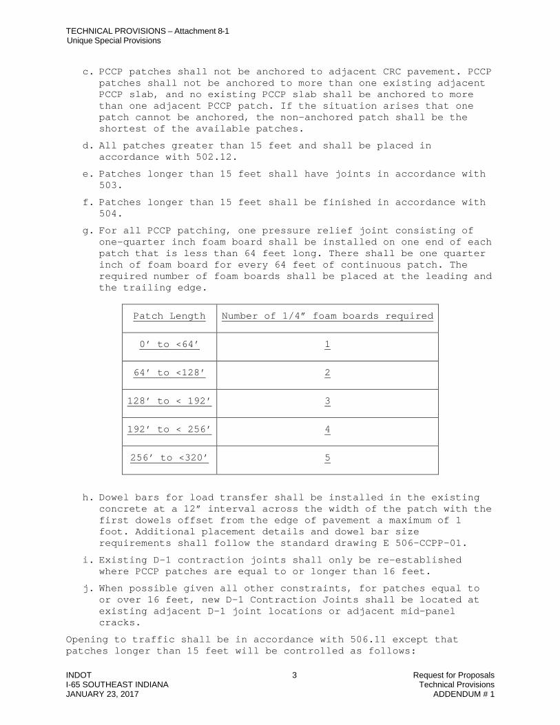
TECHNICAL PROVISIONS – Attachment 8-1 Unique Special Provisions
INDOT 3 Request for Proposals I-65 SOUTHEAST INDIANA Technical Provisions JANUARY 23, 2017 ADDENDUM # 1
c. PCCP patches shall not be anchored to adjacent CRC pavement. PCCP patches shall not be anchored to more than one existing adjacent PCCP slab, and no existing PCCP slab shall be anchored to more than one adjacent PCCP patch. If the situation arises that one patch cannot be anchored, the non-anchored patch shall be the shortest of the available patches.
d. All patches greater than 15 feet and shall be placed in accordance with 502.12.
e. Patches longer than 15 feet shall have joints in accordance with 503.
f. Patches longer than 15 feet shall be finished in accordance with 504.
g. For all PCCP patching, one pressure relief joint consisting of one-quarter inch foam board shall be installed on one end of each patch that is less than 64 feet long. There shall be one quarter inch of foam board for every 64 feet of continuous patch. The required number of foam boards shall be placed at the leading and the trailing edge.
Patch Length Number of 1/4” foam boards required
0’ to <64’ 1
64’ to <128’ 2
128’ to < 192’ 3
192’ to < 256’ 4
256’ to <320’ 5
h. Dowel bars for load transfer shall be installed in the existing concrete at a 12” interval across the width of the patch with the first dowels offset from the edge of pavement a maximum of 1 foot. Additional placement details and dowel bar size requirements shall follow the standard drawing E 506-CCPP-01.
i. Existing D-1 contraction joints shall only be re-established where PCCP patches are equal to or longer than 16 feet.
j. When possible given all other constraints, for patches equal to or over 16 feet, new D-1 Contraction Joints shall be located at existing adjacent D-1 joint locations or adjacent mid-panel cracks.
Opening to traffic shall be in accordance with 506.11 except that patches longer than 15 feet will be controlled as follows:

TECHNICAL PROVISIONS – Attachment 8-1 Unique Special Provisions
INDOT 4 Request for Proposals I-65 SOUTHEAST INDIANA Technical Provisions JANUARY 23, 2017 ADDENDUM # 1
a. Construction vehicles, equipment, or traffic may be allowed on the PCCP containing HES concrete, when a flexural strength of 425 psi is achieved. The flexural strength shall be determined by averaging two beams cast from each of the job control samples cast for that purpose.
b. Concrete meeting the mix criteria requirement of 502.04(a) shall be in accordance with 502.18 except that the modulus of rupture value shall be 425 psi or greater for all cases.
c. Any construction vehicle or equipment that may damage the PCCP shall not be used on the PCCP unless adequate protection is provided. Approved joint cutting saws may be operated on the PCCP as determined by the Contractor.

TECHNICAL PROVISIONS – Attachment 8-2 IRI for Smoothness Testing
INDOT Request for Proposals I-65 SOUTHEAST INDIANA PROJECT Technical Provisions JANUARY 23, 2017 ADDENDUM # 1
ATTACHMENT 8-2
IRI for Smoothness Testing

TECHNICAL PROVISIONS – Attachment 8-2 IRI for Smoothness Testing
INDOT Request for Proposals I-65 SOUTHEAST INDIANA PROJECT Technical Provisions JANUARY 23, 2017 ADDENDUM # 1
INDIANA DEPARTMENT OF TRANSPORTATION OFFICE OF MATERIALS MANAGEMENT
INERTIAL PROFILERS
ITM No. 917-15T 1.0 SCOPE.
1.1 This test method covers the requirements for acceptance of smoothness with an inertial profiler, calibration and operation of an inertial profiler to evaluate the smoothness of HMA and PCC pavements, and the operator approval process for use of the inertial profiler equipment.
1.2 This ITM may involve hazardous materials, operations, and equipment and may not
address all of the safety problems associated with the use of the test method. The user of the ITM is responsible for establishing appropriate safety and health practices and determining the applicability of regulatory limitations prior to use.
2.0 TERMINOLOGY. Definitions for terms and abbreviations shall be in accordance with
the Department’s Standard Specifications, Section 101 and as follows.
2.1 High-Pass Filtering. A process that reduces the effect of long wavelengths that are associated with gradual elevation changes such as hills.
2.2 International Roughness Index (IRI). A statistic used to determine the amount of
roughness in a measured longitudinal profile. The IRI is computed from a single longitudinal profile using a quarter-car simulation at 50 mph.
2.3 Line Laser. A line laser obtains a series of data points along a line, which is typically
perpendicular to the travel direction, with the line typically being 4 in. long. A single, bridged elevation is computed from this data.
2.4 Longitudinal Profile. The vertical deviations of the pavement surface taken along a line in
the direction of travel referenced to a horizontal datum.
2.5 Report Interval. The longitudinal distance between the outputs of a profile index value.
2.6 Sample Interval. The longitudinal distance between data capture points. The data include location height, and accelerometer values. These data points are combined to create one profile data point. These points, in turn, may be combined to create a final value in the reported profile.
3.0 SIGNIFICANCE AND USE. The IRI is used to assess pay factors for smoothness of HMA and PCCP
pavements. Areas of pavement that are required to be corrected to comply with specification smoothness requirements are also determined.

TECHNICAL PROVISIONS – Attachment 8-2 IRI for Smoothness Testing
INDOT Request for Proposals I-65 SOUTHEAST INDIANA PROJECT Technical Provisions JANUARY 23, 2017 ADDENDUM # 1
4.0 EQUIPMENT.
4.1 Inertial Profiler. The inertial profiler shall meet the requirements and specifications of AASHTO M 328. The equipment may be lightweight, low-speed, high-speed, full-size, motor vehicle mounted profilers. There shall be two sensors, spaced at the location of the pavement wheelpaths, that are mounted on the vehicle to measure the smoothness of the pavement. Wheelpaths are located parallel to the centerline of the pavement and approximately 3.0 ft inside all lane edges, measured transversely. The inertial profiler software shall calculate and report the IRI in in./mile from the corresponding measured true profile and permit the operator to automatically trigger the start of data collection at the designated location. The inertial profiler shall provide the measured true profiles in ProVAL electronic text files following the format in AASHTO R 57. These profile data are necessary to evaluate profiler accuracy and repeatability and to verify the height and distance measurements.
5.0 EQUIPMENT CALIBRATION VERIFICATION
5.1 General. The inertial profiler shall be calibrated on a Department test track prior to use on a project. Approval is valid for one year provided no equipment, operator, or software changes are made. Re-approval of the inertial profiler will be required if there are any changes to the equipment, operator, or software. The Contractor’s operator(s) shall operate the equipment during the test track runs. The equipment supplier may be present during the inertial profiler approval.
5.2 Longitudinal Verification
5.2.1 The distance measurement index (DMI) for longitudinal verification is done by
navigating the inertial profiler over a measured test section of at least 528 ft. A proper lead-in distance for the vehicle to attain a constant speed before the start of the section and a safe stopping distance after the end of the section will be provided. The inertial profiler will be checked at the lower limit and upper limit of the manufacturer’s recommended operational speeds.
5.2.2 The starting and ending points of the test section will be clearly marked and
measured. The length will be accurately measured to within 0.05 percent using a measuring tape.
5.2.3 The tire and electronic warm-up of the inertial profiler shall be done in
accordance with the manufacturer’s recommendations.
5.2.4 At least three auto-triggered runs at the lowest and highest test speeds of the inertial profiler shall be made. At the end of each run, the reading from the profiler’s DMI shall be recorded.

TECHNICAL PROVISIONS – Attachment 8-2 IRI for Smoothness Testing
INDOT Request for Proposals I-65 SOUTHEAST INDIANA PROJECT Technical Provisions JANUARY 23, 2017 ADDENDUM # 1
5.2.5 The absolute difference between the DMI readings and the known distance of the path tested for each run is required to be less than 0.15 percent to pass.
5.3 Block Test
5.3.1 Vertical height sensor block check tests are run after the inertial profiler has
reached operational stability as specified by the manufacturer.
5.3.2 The vertical measurement standard shall be flat plates or gauge blocks of known thickness and low thermal expansion. The blocks will be measured with a device capable of measuring the thickness to the nearest 0.001 in. Three measurements will be taken on each side of the block and the average of the measurements will be determined. The blocks shall be marked with the known average thickness and the blocks certified as being accurate to within 0.001 in. As a minimum, a smooth base plate and both 1-in. and a 2-in. gauge blocks are required. Additional 0.25-in. and 0.50 in. blocks shall be supplied if there is a failure with the 1.00 in. or 2.00 in. blocks. The owner of the inertial profiler shall furnish the base plates and blocks.
5.3.3 The block test is conducted on a relatively flat and level area. The inertial
profiler shall not be moved in any way and under windy conditions the block test shall be performed indoors.
5.3.4 The smooth base plate is placed under the height sensor of the inertial profiler
and the height measurements are obtained by the system.
5.3.5 The 1.00-in. block is placed underneath the height sensor on top of the base plate and ten height measurements are obtained by the system and averaged.
5.3.6 The 1.00-in. block is carefully removed from the base plate and replaced with
the 2.00-in. block. Another set of ten height measurements are obtained and averaged.
5.3.7 The absolute difference between the computed block thickness and the known
average block thickness for the 1-in. and 2-in. blocks shall be less than or equal to 0.01 in. to pass.
5.3.8 If the equipment fails the block test for the 1.00-in. or 2.00-in. tests, the full
range of tests with the 0.25-in., 0.50-in., 1.00-in., and 2.00 in. blocks shall be performed.
5.3.9 The operator of the profiler shall tabulate the measurements and record the
measurements in a calibration log.

TECHNICAL PROVISIONS – Attachment 8-2 IRI for Smoothness Testing
INDOT Request for Proposals I-65 SOUTHEAST INDIANA PROJECT Technical Provisions JANUARY 23, 2017 ADDENDUM # 1
5.4 Bounce Test
5.4.1 Vertical height sensor bounce check tests are run after the inertial profiler has reached operational stability as specified by the manufacturer.
5.4.2 The inertial profiler shall be placed on a surface as flat and level as possible.
5.4.3 A thin, smooth, flat, non-glossy material plate is centered under each sensor.
5.4.4 Using the equipment’s normal data collection software, a data collection run is
done using a simulated travel speed at the midpoint of the manufacturer’s recommended operational speed range. (Note 1)
Note 1: The only difference between a bounce test and a normal data collection run is that there is an artificial longitudinal travel signal supplied and the vehicle is not actually traveling along the road. The bounce test utilizes the same data collection software and routines used during normal data collection.
5.4.5 The bounce test will require a profile collection run with a minimum simulated
travel distance of 2184 ft.
5.4.6 The inertial profiler shall collect a minimum of 828 ft of static profile with the equipment as motionless as possible.
5.4.7 The sensor(s) shall be moved vertically for a total displacement of approximately
1 to 2 in. while keeping the sensors as close to perpendicular to the surface as possible during the movement (Note 2). This movement is required to be continued until a minimum of 528 ft of simulated longitudinal distance has been covered.
Note 2: A yardstick may be helpful until the operator is familiar with this procedure. The typical method for full-size, high-speed profilers is to push the mounting system (bumper) down an inch or so and let the vehicle suspension rebound to create the total vertical travel of 1 to 2 in. The typical method for lightweight, slow-speed profilers is to stand toward the center of the vehicle platform and move up and down such that all four corners of the vehicle suspension travel approximately 1 to 2 in. vertically.
5.4.8 After a minimum of 528 ft of bounce profile is collected, the inertial profiler shall
collect an additional minimum of 828 ft of static profile.

TECHNICAL PROVISIONS – Attachment 8-2 IRI for Smoothness Testing
INDOT Request for Proposals I-65 SOUTHEAST INDIANA PROJECT Technical Provisions JANUARY 23, 2017 ADDENDUM # 1
5.4.9 The profiles shall be analyzed using the ProVAL software to compute the continuous IRI with a 528-ft base length for each profile collected. The first and last 300 ft of the profile shall not be included in the analysis as these distances are the lead-in and lead-out distances.
5.4.10 The static portion IRI results shall be less than 3 in./mile and the bounce portion
IRI shall be less than 8 in./mile for the profiler to pass. The two static IRI portions shall be approximately the same. These requirements apply to each sensor of the inertial profiler.
5.4.11 The operator of the inertial profiler shall tabulate the measurements and record
the measurements in a calibration log.
5.5 Test Track Verification
5.5.1 The test track shall be the same test section used for the DMI verification.
5.5.2 Test track approval will consist of two sets of five runs of the inertial profiler device.
5.5.3 Electronic copies of all road profiles collected on the two sets of five runs,
including lead in and lead out distance, shall be submitted to the Department in ProVAL compatible format.
5.5.4 The Department will select up to four subsections within the two sets and
establish reference values for IRI. All indices will be generated using ProVAL software.
5.5.5 For IRI, each of the five reported run values will be within 5.0 percent of the
average of those values for each subsection to demonstrate repeatability of the equipment.
5.5.6 The average of the five reported run values shall be within 5 percent of the
reference value or within 5 in./mile for each subsection, whichever is greater, to demonstrate reproducibility of the equipment.
5.5.7 The Department will allow one additional set of five runs if there is a problem
with the verification of the inertial profiler. 6.0 CERTIFICATION OF INERTIAL PROFILERS.
6.1 The Office of Research and Development will certify all inertial profilers.
6.2 The inertial profiler will be certified once per calendar year and prior to use on a contract in the same year.

TECHNICAL PROVISIONS – Attachment 8-2 IRI for Smoothness Testing
INDOT Request for Proposals I-65 SOUTHEAST INDIANA PROJECT Technical Provisions JANUARY 23, 2017 ADDENDUM # 1
6.3 A certificate of compliance will be issued to the Contractor for the inertial profiler being calibrated. The certification of compliance will include the following information:
6.3.1 Manufacturer Name
6.3.2 Model
6.3.3 Serial Number
6.3.4 Owner Identification
6.3.5 Inspection and Inactive Date
6.3.6 Calibration Settings
6.3.7 Software Version and Release
6.3.8 Operator Name
6.3.9 Filter Settings
6.3.10 Sampling Interval
6.4 Modifications to the inertial profiler will require a recertification in accordance with 5.0.
7.0 EQUIPMENT OPERATOR APPROVAL.
7.1 All operators of the inertial profilers shall demonstrate the ability to successfully perform the following on the equipment being certified on the Department test track:
7.1.1 Distance Measurement Instrument calibration
7.1.2 Static height sensors calibration
7.1.3 Bounce test
7.1.4 Road profiles in a ProVAL compatible electronic format
7.1.5 Smoothness indices using ProVAL software
7.1.6 Smoothness indices in Excel format for pay adjustment
7.1.7 Profile log sheet for profiles collected on the test track

TECHNICAL PROVISIONS – Attachment 8-2 IRI for Smoothness Testing
INDOT Request for Proposals I-65 SOUTHEAST INDIANA PROJECT Technical Provisions JANUARY 23, 2017 ADDENDUM # 1
7.2 Each operator will be given an approval letter indicating that the operator is approved to operate that particular inertial profiler. The operator approval is valid for one year.
7.3 Operators may be removed from approval for failure to follow the requirements for
equipment operation, failure to perform site verification and testing as required, failure to produce accurate and timely roadway profiles, or any other failure to follow the requirements for surface smoothness measurements.
8.0 PROCEDURE FOR PROJECT OPERATION OF INERTIAL PROFILERS.
8.1 The inertial profiler shall be operated by a Contractor Technician that is approved by the Department.
8.2 The inertial profiler shall be certified and calibrated in accordance with sections 5.0 and
6.0. The Engineer may request a demonstration of distance, height, and bounce measurement accuracy and verify computer settings at any time. If the inertial profiler does not meet the verification requirements or there are equipment changes noted by the Engineer, the inertial profiler shall not be used on the project.
8.3 The certificate of compliance shall be presented to the Engineer prior to use of the
inertial profiler on the project. The Engineer will check the distance, height, and bounce measurements of the inertial profiler on the project.
8.4 An agreed known distance measurement on the project will be checked in accordance
with 5.2 to verify the DMI. The tolerance for the distance measurement will be 0.15 percent.
8.5 The height measurement using the block test will be checked in accordance with 5.3.
The Contractor shall provide a caliper accurate to 0.001 in. for verifying the gauge block dimensions. The tolerance for the height measurement will be 0.01 in.
8.6 The bounce test will be done in accordance with 5.4. The IRI for the bounce test will be
less than or equal to 8 in./mile.
8.7 The inertial profiler shall be operated in accordance with the following:
8.7.1 The roadway shall be cleaned of all debris and other loose material. Data shall be collected on a dry pavement. Collecting data on damp pavements without any standing water may be acceptable if approved by the Engineer.

TECHNICAL PROVISIONS – Attachment 8-2 IRI for Smoothness Testing
INDOT Request for Proposals I-65 SOUTHEAST INDIANA PROJECT Technical Provisions JANUARY 23, 2017 ADDENDUM # 1
8.7.2 The inertial profiler shall be operated at a relatively constant speed within the manufacturer’s recommended operational speed range. All data collected outside this speed range is not valid and re-measuring these pavement sections will be required.
8.7.3 A lead-in length of roadway of at least 300 ft. is required. Shorter lead-in
sections may be considered if the physical constraints require a shorter length and other contract conditions make a shorter length acceptable.
8.7.4 Two longitudinal traces are required in the wheelpaths. The inertial profiler shall
be operated 3.0 ± 0.5 ft from and parallel to both edges of the lane.
8.7.5 Measurements shall be taken in the direction of traffic. If this is not practical and data is collected in the other direction, the direction will be noted in the report. For lanes utilized by traffic in either direction, the inertial profiler shall be operated in the direction of increasing station numbers.
8.7.6 Data shall be collected at the end of the paving operation or staged as required
by the Engineer.
8.7.7 The data shall be submitted to the Engineer in a format readable by ProVAL. The Checklist for Verification of the Inertial Profiler (Appendix A) will be completed by the Engineer.
8.7.8 The areas exempt from measurement are as follows:
1. The first and last 50 ft within the paving limits
2. From 50 ft before through 50 ft after each paving exception
3. From 50 ft before through 50 ft after each at-grade railroad crossing
4. From 50 ft before through 50 ft after each casting located within 4.0 ft
measured laterally from the edge of lane. 9.0 REPORTS.
9.1 The Engineer will report the IRI for each section to the Contractor within seven calendar days from the date the ProVAL data was received.
9.2 The Engineer will notify the Contractor of the sections that do not comply with the
smoothness specifications and require correction.
9.3 The ProVAL(s) data will be maintained with the final construction file.
CHECKLIST FOR VERIFICATION OF INERTIAL PROFILERS [ ] Profile Operator submitted a Certification Letter for the inertial profiler and the operator issued by

TECHNICAL PROVISIONS – Attachment 8-2 IRI for Smoothness Testing
INDOT Request for Proposals I-65 SOUTHEAST INDIANA PROJECT Technical Provisions JANUARY 23, 2017 ADDENDUM # 1
the Office of Research and Development [ ] Engineer confirmed the operation of the inertial profiler equipment as follows:
Verification Test Actual Measured Difference Tolerance Height Sensor Block Test ≤ 0.01 in. Bounce Test < 8 in./mi. DMI calibration Test < 0.15 %
[ ] Engineer given copy of data to include raw data files, cropped data files, smoothness data, localized
smoothness deficiencies and data collection log sheet [ ] Engineer reviewed the procedure for correcting the profile of non-complying pavement in the Quality
Control Plan [ ] Post corrective action profile data received indicating that corrective action repaired violations. Remarks:__________________________________________________________________________ __________________________________________________________________________________ __________________________________________________________________________________ __________________________________________________________________________________ __________________________________________________________________________________ Verified By:_________________________________________ Date:________________________

TECHNICAL PROVISIONS – Attachment 8-2 IRI for Smoothness Testing
INDOT Request for Proposals I-65 SOUTHEAST INDIANA PROJECT Technical Provisions JANUARY 23, 2017 ADDENDUM # 1
SECTION 501.25, BEGIN LINE 375, DELETE AND INSERT AS FOLLOWS: 501.25 Pavement Smoothness
Pavement smoothness will be accepted by means of a profilograph inertial profiler, a 16 ft long straightedge, or a 10 ft long straightedge as described below. (a) Profilograph Inertial Profiler with Smoothness Pay Adjustments When a pay item for Profilograph Inertial Profiler, PCCP is included in the contract, the Contractor shall furnish, calibrate, and operate an approved profilograph inertial profiler in accordance with ITM 912 917 for the acceptance of longitudinal smoothness on the mainline traveled way and ramps, including adjacent acceleration or deceleration lane, where both of the following conditions are met: 1. The design speed is greater than 45 mph.
2. The traveled way or ramp lane width and slope is constant and is 0.5 mi in length or longer.
The profilogram profiles,International Roughness Index (IRI) results including smoothness histograms and areas of localized roughness, and fixed interval IRI results shall become the property of the Department. The profilograph inertial profiler shall remain the property of the Contractor. The project area, less paving exceptions and areas exempt from profilograph inertial profiler operation will be in accordance with ITM 9127., will be divided into individual smoothness sections measuring 0.1 mi in length for each lane. Partial length smoothness sections adjacent to project limits, paving exceptions, or areas exempt from profilograph operation will be considered in accordance with ITM 912. If the posted speed limit for an entire smoothness section is less than or equal to 45 mph, the section will be exempt from profilograph inertial profiler operation and the smoothness within the section will be accepted by a 16 ft straightedge. If the posted speed limit is greater than 45 mph for a portion of a smoothness section and is less than or equal to 45 mph for the remainder, the section smoothness acceptance will be as follows:
1. By profilograph inertial profiler for the portion of the section with a posted speed limit greater than 45 mph.
2. By 16 ft straightedge In accordance with 501.25(b) or (c) for the
portion of the section with a posted speed limit less than or equal to 45 mph.
At locations where the profilograph inertial profiler is required, all high or low point deviations which are greater than 0.3 in. with an IRI greater than 150 in./mile utilizing a 25 ft

TECHNICAL PROVISIONS – Attachment 8-2 IRI for Smoothness Testing
INDOT Request for Proposals I-65 SOUTHEAST INDIANA PROJECT Technical Provisions JANUARY 23, 2017 ADDENDUM # 1
window shall be corrected. Corrections shall be made in accordance with 501.25(cd)
b) Inertial Profiler without Smoothness Pay Adjustments For contracts which include the Inertial Profiler, PCCP pay item, the Inertial Profiler will be used to simulate the 16 ft long straightedge to accept longitudinal smoothness at the following locations:
1. All mainline traveled way lanes longer than 0.1 mi and shorter than 0.5 mi.
2. All mainline traveled way lanes within smoothness sections with posted speed limits less than or equal to 45 mph throughout the entire section length.
3. All turn lanes, including bi-directional left turn lanes longer than 0.1 mi.
4. All ramps
5. All acceleration and deceleration lanes associated with ramps with design speeds of
45 mph or less and longer than 0.1 mi. (b c) 16 ft Straightedge and 10 ft Straightedge The Department will furnish and operate 16 ft and 10 ft straightedges as described below. The 16 ft straightedge is used to accept smoothness along the direction of mainline traffic and the 10 ft straightedge is used to accept smoothness transverse to the direction of mainline traffic. This includes longitudinal smoothness on public road approaches and median crossovers. For contracts which include the profilograph, Inertial Profiler, PCCP pay item, the 16 ft long straightedge will be used to accept longitudinal smoothness at the following locations:
1. All mainline traveled way lanes shorter than 0.1 mi.
2. All mainline traveled way lanes at locations exempted from profilograph inertial profiler operation in accordance with ITM 912 917.
3. All tapers.
4. All turn lanes, including bi-directional left turn lanes shorter than 0.1 mi.
5. All acceleration and deceleration lanes associated with ramps with
design speeds of 45 mph or less and shorter than 0.1 mi. 6. All shoulders.

TECHNICAL PROVISIONS – Attachment 8-2 IRI for Smoothness Testing
INDOT Request for Proposals I-65 SOUTHEAST INDIANA PROJECT Technical Provisions JANUARY 23, 2017 ADDENDUM # 1
For contracts where the profilograph inertial profiler is not used for smoothness acceptance, the 16 ft straightedge will be used to accept longitudinal smoothness at the above locations and on all mainline traveled way lanes and ramps with design speeds greater than 45 mph. Smoothness acceptance on ramp acceleration or deceleration lanes will also be accepted by the 16 ft straightedge. The 10 ft long straightedge shall be used for transverse slopes, approaches, and crossovers. As soon as the PCCP has cured sufficiently, the smoothness may be checked. The Department may direct that the pavement profile be evaluated within 24 h following placement. When profile testing is consistently outside pavement surface tolerances the paving operation shall be discontinued until an amended QCP is submitted.

TECHNICAL PROVISIONS – Attachment 8-2 IRI for Smoothness Testing
INDOT Request for Proposals I-65 SOUTHEAST INDIANA PROJECT Technical Provisions JANUARY 23, 2017 ADDENDUM # 1
(cd) Smoothness Correction Pavement smoothness variations outside specified tolerances shall be corrected by grinding with a groove type cutter or by replacement. Grinding will not be allowed until the PCCP is 10 days old or the flexural strength test is 550 psi or greater. The grinding of the pavement to correct the profile shall be accomplished in either the longitudinal or the transverse direction. The PCCP texture after grinding shall be uniform. If the grinding operation reduces the tining grooves to a depth of less than 1/16 in. and the longitudinal length of the removal area exceeds 15 ft, or two or more areas are within 30 ft of each other, the PCCP shall be re-textured in accordance with 504.03. At locations where the profilograph inertial profiler is used, all areas having a high or low point deviation in excess of 0.3 in. 150 in./mile in 25 ft shall be corrected. After the corrective action is complete, the profilograph inertial profiler shall be operated throughout the entire affected smoothness section to verify the adequacy of the corrective action. At locations where the 16 ft straightedge is used, the pavement variations shall be corrected to 1/4 in. or less. At locations where the 10 ft straightedge is used, the pavement variations shall be corrected to 1/8 in. or less. SECTION 501.28, BEGIN LINE 619, DELETE AND INSERT AS FOLLOWS: (d) Smoothness When the pavement smoothness is tested with an profilograph inertial profiler, pavement payment will be based on a zero blanking band on the final profile index continuous IRI smoothness histograms. A Quality Assurance Pay Factor, PFs, for smoothness will apply to the planned thickness of the PCCP. The quality assurance adjustment for each section will include the total area of each pavement lane measured by the profilograph inertial profiler for 0.1 mi long section represented by the profile index IRI histograms calculated by the following formula: qs = (PFs – 1.00) x A x U where: qs = quality assurance adjustment for smoothness for one section PFs = pay factor for smoothness A = area of the section, sq yd U = unit price for the material $/sq yd.
x U Ax 5.0K =
)Z (Y * 1) - (PF *KQ ii
n
1i
si s +∑
=
=
where: Qs = quality assurance adjustment for smoothness
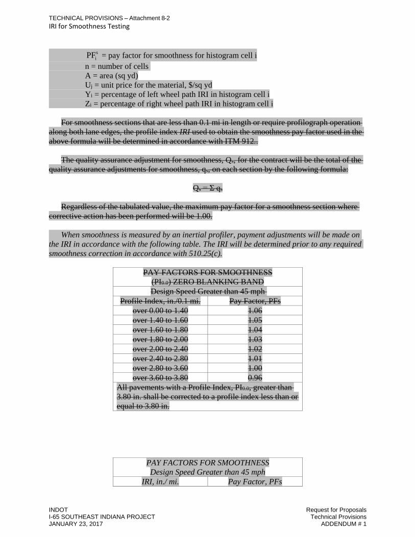
TECHNICAL PROVISIONS – Attachment 8-2 IRI for Smoothness Testing
INDOT Request for Proposals I-65 SOUTHEAST INDIANA PROJECT Technical Provisions JANUARY 23, 2017 ADDENDUM # 1
siPF = pay factor for smoothness for histogram cell i
n = number of cells A = area (sq yd) Uj = unit price for the material, $/sq yd Yi = percentage of left wheel path IRI in histogram cell i Zi = percentage of right wheel path IRI in histogram cell i For smoothness sections that are less than 0.1 mi in length or require profilograph operation along both lane edges, the profile index IRI used to obtain the smoothness pay factor used in the above formula will be determined in accordance with ITM 912.. The quality assurance adjustment for smoothness, Qs, for the contract will be the total of the quality assurance adjustments for smoothness, qs, on each section by the following formula:
Qs = Σ qs
Regardless of the tabulated value, the maximum pay factor for a smoothness section where corrective action has been performed will be 1.00. When smoothness is measured by an inertial profiler, payment adjustments will be made on the IRI in accordance with the following table. The IRI will be determined prior to any required smoothness correction in accordance with 510.25(c).
PAY FACTORS FOR SMOOTHNESS (PI0.0) ZERO BLANKING BAND Design Speed Greater than 45 mph
Profile Index, in./0.1 mi. Pay Factor, PFs over 0.00 to 1.40 1.06 over 1.40 to 1.60 1.05 over 1.60 to 1.80 1.04 over 1.80 to 2.00 1.03 over 2.00 to 2.40 1.02 over 2.40 to 2.80 1.01 over 2.80 to 3.60 1.00 over 3.60 to 3.80 0.96
All pavements with a Profile Index, PI0.0, greater than 3.80 in. shall be corrected to a profile index less than or equal to 3.80 in.
PAY FACTORS FOR SMOOTHNESS Design Speed Greater than 45 mph
IRI, in./ mi. Pay Factor, PFs

TECHNICAL PROVISIONS – Attachment 8-2 IRI for Smoothness Testing
INDOT Request for Proposals I-65 SOUTHEAST INDIANA PROJECT Technical Provisions JANUARY 23, 2017 ADDENDUM # 1
over 0 to 35 1.08 over 35 to 40 1.07 over 40 to 45 1.05 over 50 to 55 1.02 over 55 to 60 1.01 over 60 to 70 1.00 over 70 to 75 0.99 over 75 to 80 0.98 over 80 to 85 0.96 over 85 to 90 0.95
SECTION 501.31, BEGIN LINE 716, INSERT AND DELETE AS FOLLOWS: 501.31 Basis of Payment The accepted quantities of QC/QA-PCCP will be paid for at the contract unit price per square yard for the thickness specified, complete in place. Payment for furnishing, calibrating, and operating the profilograph inertial profiler, and furnishing profile IRI information will be made at the contract lump sum price for profilograph inertial profiler, PCCP. Adjustments to the contract payment with respect to flexural strength, thickness, air content, range and smoothness will be included in a quality assurance adjustment pay item in accordance with 109.05.1. Milled shoulder corrugations will be paid for in accordance with 606.03. Payment for pavement thickness determinations will be made at the contract lump sum price for coring, PCCP. A change order in accordance with 109.05 will be developed to adjust the cost of coring when the final QC/QA-PCCP quantity differs from the bid quantity by more than 2,400 sq yd. This adjustment covers the cost of cores for the adjusted quantity of QC/QA-PCCP. The adjustment, plus or minus, will be based on the difference in the number of sublots, rounded to the nearest full sublots, times $100. Payment will be made under: Pay Item Pay Unit Symbol Coring, PCCP .......................................................................... LS Profilograph Inertial Profiler, PCCP ...................................... LS QC/QA-PCCP, __________ in. ........................................... SYS thickness The cost of trial batch demonstrations shall be included in the cost of PCCP. The price of profilograph inertial profiler, PCCP will be full compensation regardless of how
TECHNICAL PROVISIONS – Attachment 8-2 IRI for Smoothness Testing
INDOT Request for Proposals I-65 SOUTHEAST INDIANA PROJECT Technical Provisions JANUARY 23, 2017 ADDENDUM # 1
often the profilograph inertial profiler is used or how many profilograms are produced often the IRI is determined.
502.03 The cost of corrections for pavement smoothness and re-texturing shall be included in the cost of QC/QA-PCCP. The cost of coring and refilling of the pavement holes for appeals shall be included in the cost of QC/QA-PCCP. Traffic control for appeals shall be supplied with no additional payment. Removal and replacement of QC/QA-PCCP damaged by freezing shall be with no additional payment. SECTION 502.20, LINE 362, INSERT AND DELETE AS FOLLOWS: 502.20 Pavement Smoothness Pavement smoothness will be in accordance with 501.25 except profilograph inertial profiler requirements will not apply.

TECHNICAL PROVISIONS – Attachment 8-3 Certified HMA Producer Program
INDOT Request for Proposals I-65 SOOTHEAST INDIANA PROJECT Technical Provisions JANUARY 23, 2017 ADDENDUM # 1
ATTACHMENT 8-3
CERTIFIED HMA PRODUCER PROGRAM
TECHNICAL PROVISIONS – Attachment 8-3 Certified HMA Producer Program
INDOT 1 Request for Proposals I-65 SOUTHEAST INDIANA PROJECT Technical Provisions JANUARY 23, 2017 ADDENDUM # 1
INDIANA DEPARTMENT OF TRANSPORTATION OFFICE OF MATERIALS MANAGEMENT
CERTIFIED HOT MIX ASPHALT PRODUCER PROGRAM
ITM 583-16P
1.0 SCOPE.
1.1 This procedure covers the requirements for a HMA plant to become a Certified Hot Mix Asphalt Producer. Mixtures produced shall be QC/QA HMA in accordance with 401, HMA in accordance with 402, and Stone Matrix Asphalt (SMA) in accordance with 410.
1.2 This procedure may involve hazardous materials, operations and equipment and may
not address all of the safety problems associated with the use of the test method. The user of this ITM is responsible for establishing the appropriate safety and health practices and determining the applicability of regulatory limitations prior to use.
2.0 REFERENCES. Documents required by the Program may be maintained electronically or
by hard copy.
2.1 AASHTO Standards. R 30 Mixture Conditioning of Hot Mix Asphalt R 35 Superpave Volumetric Design for Hot Mix Asphalt (HMA) R 46 Designing Stone Matrix Asphalt (SMA) T 2 Sampling of Aggregates T 11 Materials Finer Than 75-µm (No. 200) Sieve in Mineral Aggregates
by Washing T 27 Sieve Analysis of Fine and Coarse Aggregates T 30 Mechanical Analysis of Extracted Aggregate R 66 Sampling Bituminous Materials T 166 Bulk Specific Gravity of Compacted Hot Mix Asphalt (HMA)
Using Saturated Surface-Dry Specimens. T 209 Theoretical Maximum Specific Gravity and Density of Hot Mix
Asphalt Paving Mixtures T 248 Reducing Samples of Aggregate to Testing Size T 255 Total Evaporable Moisture Content of Aggregate by Drying T 269 Percent Air Voids in Compacted Dense and Open Asphalt Mixtures T 275 Bulk Specific Gravity of Compacted Hot Mix Asphalt (HMA) Using
Paraffin-Coated Specimens T 305 Determination of Draindown Characteristics in Uncompacted Asphalt
Mixtures T 312 Preparing and Determining the Density of Hot Mix Asphalt (HMA)
Specimens by Means of the Superpave Gyratory Compactor

TECHNICAL PROVISIONS – Attachment 8-3 Certified HMA Producer Program
INDOT 2 Request for Proposals I-65 SOUTHEAST INDIANA PROJECT Technical Provisions JANUARY 23, 2017 ADDENDUM # 1
T 331 Bulk Specific Gravity and Density of Compacted Asphalt Mixtures Using Automatic Vacuum Sealing Method
T 344 Evaluation of Superpave Gyratory Compactor (SGC) Internal Angle of Gyration Using Simulated Loading
2.2 ASTM Standards.
D 5821 Determining the Percentage of Fractured Particles in Coarse
Aggregate
2.3 ITM Standards. 207 Sampling Stockpiled Aggregates 220 Class AS Aggregate for Use in SMA Mixture 571 Quantitative Extraction of Asphalt/Binder and Gradation of
Extracted Aggregate from HMA Mixtures 572 Drying HMA Mixtures 580 Sampling HMA 581 Performance Graded Binder Approved Supplier Certification (ASC) Program 584 Bulk Specific Gravity of Aggregate Blends with Recycled
Aggregate 586 Binder Content by Ignition 587 Reducing HMA Samples to Testing Size 588 Percent Within Limits (PWL) 590 Total Aggregate Bulk Specific Gravity Determination from
Extracted HMA or SMA Mixture 591 Delta Pb (ΔPb) Determination for Dense Graded HMA or SMA
Mixture 902 Verifying Sieves 903 Verifying Ovens 905 Verifying Vacuum Systems 906 Verifying Mechanical Shakers
908 Verifying Calibrations Settings for Superpave Gyratory Compactors
909 Verifying Thermometers 910 Verifying Balances 916 Verification of Calipers
2.4 A Certified HMA plant laboratory shall have the following current documents on file:
2.4.1 Indiana Department of Transportation Standard Specifications
(Includes applicable Supplemental Specifications)
2.4.2 Pertinent contract Special Provisions

TECHNICAL PROVISIONS – Attachment 8-3 Certified HMA Producer Program
INDOT 3 Request for Proposals I-65 SOUTHEAST INDIANA PROJECT Technical Provisions JANUARY 23, 2017 ADDENDUM # 1
2.4.3 Indiana HMA Quality Assurance Certified Technician Program
Manual
2.4.4 All applicable ITM, AASHTO, and ASTM Test Methods
2.4.5 Testing equipment calibrations or verifications
2.4.6 Mix design, DMF, for each Mixture
2.4.7 Fines correction data for the mixture and recycled materials for each DMF 2.4.8 Type A certifications for the PG 58-28 and PG 64-22 binder materials
2.4.9 Type A certifications for the SBR polymer latex
2.4.10 PG 64-28 and PG 70-22 binder test reports from an AASHTO accredited
laboratory whenever PG 58-28 and PG 64-22 are in-line blended with SBR polymer latex
2.4.11 Process control test results
2.4.12 Type D certifications issued to active Department contracts
2.5 A Certified HMA plant shall have the following current documents on file:
2.5.1 The Quality Control Plan (QCP) for the HMA plant
2.5.2 Bill of ladings of the binder from each Supplier for a minimum period of
three years
2.5.3 Weigh tickets from most current date of production of HMA
2.5.4 Instructions from the Supplier concerning storage and handling of the binder
2.5.5 Flow meter calibration reports and flow computer printouts whenever in-line blending with SBR polymer latex
2.5.6 The IDEM Legitimate Use Approval letter from the post-consumer asphalt
shingle processing company
2.5.7 HMA plant calibrations for each DMF
2.5.8 Daily diary
2.5.9 Annual calibration of HMA plant scales and verification of meters

TECHNICAL PROVISIONS – Attachment 8-3 Certified HMA Producer Program
INDOT 4 Request for Proposals I-65 SOUTHEAST INDIANA PROJECT Technical Provisions JANUARY 23, 2017 ADDENDUM # 1
2.5.10 Fiber certification from the manufacturer
2.5.11 Instructions from the manufacturer concerning storage and handling of fibers
3.0 TERMINOLOGY. Definitions for terms and abbreviations will be in accordance with the Department’s Standard Specifications Section 101 and the following:
3.1 Addenda. Any addition or deletion to the QCP
3.2 Addenda Summary Sheet. A page of the QCP that is used to record a brief description of addenda until such time that the revisions are incorporated into the QCP
3.3 Actual Binder Content. The binder content determined in accordance with ITM 586
or the total of the binder content determined in accordance with ITM 571 and the binder absorption percent from the DMF
3.4 Certified Asphalt Technician. An individual who has successfully completed the
requirements of the Department Hot Mix Asphalt QA/QC Certified Technician Training Program
3.5 Certified HMA Plant. A HMA plant that meets the requirements of the Program,
continues to be under the same ownership, and is approved by the Department 3.6 Corrective Action. Corrective action shall include, but is not limited to,
investigation for cause, correction of known cause, or re-testing 3.7 Coarse Aggregate. Aggregate that has a minimum of 20 percent retained on the No.
4 sieve 3.8 District. The Department District Office responsible for administrating the materials
and tests function in a local area of the state
3.9 Fine Aggregate. Aggregate that is 100 percent passing the 3/8 in. sieve and a minimum of 80 percent passing the No. 4 sieve
3.10 Mixture. QC/QA HMA, HMA, or SMA produced for the Department’s use in accordance with ITM 583 and the Specifications 3.11 Moving Average. Average of the last four or five tests as stated in the QCP 3.12 National Institute of Standards and Technology (NIST). A federal technology
agency that develops and applies technology, measurements, and standards

TECHNICAL PROVISIONS – Attachment 8-3 Certified HMA Producer Program
INDOT 5 Request for Proposals I-65 SOUTHEAST INDIANA PROJECT Technical Provisions JANUARY 23, 2017 ADDENDUM # 1
3.13 Office of Materials Management. An office of the Indiana Department of Transportation, located at 120 S. Shortridge Rd. in Indianapolis, Indiana 46219-0389
3.14 Producer. A company or owner who shall assume responsibility for a Certified
HMA Plant. A Producer, in accordance with ITM 581, may modify a PG binder from a Supplier by in-line blending SBR polymer latex at the HMA plant for immediate use.
3.15 Program. ITM 583, Certified Hot Mix Asphalt Producer Program 3.16 QCP Annex. A page of the QCP, located in the Appendix, that is used to record
revisions for HMA Plant major components, Certified Asphalt Technicians, and movement of the HMA Plant
3.17 Qualified Technician. An individual who has successfully completed the written
and proficiency testing requirements of the Department Qualified Laboratory and Technician Program
3.18 Supplier. A Supplier shall be a refinery or terminal that produces modified or
unmodified PG binders in accordance with ITM 581. 3.19 Water-Injection Foaming. Water-injection foaming is a technology that allows a
reduction in the temperature at which mixtures are produced and placed. 4.0 SIGNIFICANCE AND USE. The Certified Hot Mix Asphalt Producer Program is a
program whereby the Producer takes responsibility for the production of quality mixture in accordance with contract requirements, and the Department monitors the Producers production, sampling, and testing procedures.
5.0 PRODUCER PERSONNEL. The Producer personnel shall include a Management
Representative, Certified Asphalt Technician, and a Qualified Technician, if applicable.
5.1 Management Representative. The Management Representative shall be responsible for all aspects of mixture production and control at the HMA plant and on the pavement as required by the Program.
5.2 Certified Asphalt Technician. The Certified Asphalt Technician shall compact
and analyze the mixture specimens, and perform the maximum specific gravity test. The technician shall supervise all other sampling and testing of materials, the maintenance of control charts, and the maintenance of the diary.
5.3 Qualified Technician. The Qualified Technician shall conduct all sampling and
testing used for acceptance of materials produced in accordance with 402. The tests required to determine the air void content in the HMA shall be conducted by a Certified Asphalt Technician.

TECHNICAL PROVISIONS – Attachment 8-3 Certified HMA Producer Program
INDOT 6 Request for Proposals I-65 SOUTHEAST INDIANA PROJECT Technical Provisions JANUARY 23, 2017 ADDENDUM # 1
6.0 LABORATORY.
6.1 Process control testing shall be performed at the HMA Plant or as permitted in 6. 3. The Producer shall provide and maintain a laboratory for process control testing. The laboratory shall have the necessary space, equipment, and supplies for the tests to be performed.
6.2 The laboratory testing equipment shall meet the requirements of the test methods
identified for the required sampling and testing, except that an electronic balance shall be provided. The electronic balance shall be readable to 0.1 g and accurate to 0.2 g or 0.1 percent of the test load, whichever is greater, at any point within the range of use. The gyratory compactor shall tilt the specimen mold at an average internal angle of 1.16 ± 0.02° as determined in accordance with AASHTO T 344. The gyratory compactor shall be on the Department’s List of Approved Superpave Gyratory Compactors.
6.3 Performance of process control tests at laboratory facilities other than at the HMA
Plant will be permitted provided the laboratory facilities are owned by the Producer, all test procedure criteria are satisfied in accordance with 6.2, and the test results are furnished in writing to the HMA Plant within two working days.
6.4 The Engineer shall be permitted access to inspect any laboratory used for process
control testing, and witness process control activities during production of mixtures. 7.0 TEST EQUIPMENT CALIBRATION.
7.1 The test equipment furnished by the Producer shall be properly calibrated or verified and maintained within the limits described in the applicable test method.
7.2 The Producer shall calibrate or verify equipment at the frequency indicated. 7.3 The equipment calibration or verification documentation shall be kept on file for a
minimum period of three years and include:
7.3.1 A description of the equipment calibrated or verified including Model and Serial Number
7.3.2 Name of the person performing the calibration or verification
7.3.3 Identification of the calibration equipment used, if any (namely, standard
weights, proving rings, thermometers, etc.)
7.3.4 Last date calibration or verification was performed and next due date
7.3.5 A reference to the procedure used

TECHNICAL PROVISIONS – Attachment 8-3 Certified HMA Producer Program
INDOT 7 Request for Proposals I-65 SOUTHEAST INDIANA PROJECT Technical Provisions JANUARY 23, 2017 ADDENDUM # 1
7.3.6 Detailed records showing the results of the calibration or verification performed
7.4 The testing equipment shall be calibrated or verified in accordance with the
following:
Equipment Requirement Minimum Frequency Procedure
Balances Standardize 12 mo. ITM 910
Gyratory Compactor
Verify Ram Pressure, Angle of Gyration, Frequency of Gyration, LVDT
1 mo. ITM 908
Gyratory Compactor Internal Angle Verification 12 mo. AASHTO T 344
Gyratory Mold and Plate Dimensions Verification 12 mo. AASHTO T 312
Ignition Oven Conduct Lift Test Weekly Operators Manual
Ignition Oven Balance Standardize 12 mo. ITM 910
Mechanical Shakers Verify Sieving Thoroughness 12 mo. ITM 906
Ovens Verify Temperature Settings 12 mo. ITM 903
Sieves Verify Physical Condition 12 mo. ITM 902
Thermometers Verification 12 mo. ITM 909 Vacuum Chamber Verification 3 mo. ITM 905
7.5 The equipment used to calibrate or verify the testing equipment shall be NIST
traceable and shall be calibrated or verified in accordance with the following frequencies:
Calibration Equipment Testing Equipment Minimum
Frequency
Bore Gauge Gyratory Compactor Molds – AASHTO T 312 12 mo.
Calipers Gyratory Compactor Molds – AASHTO T 312 12 mo.
Dynamometer or Load Cell & Proving Ring Gyratory Compactor – AASHTO T 312 24 mo.
Height Gage Blocks Gyratory Compactor – AASHTO T 312 24 mo. Height Billet Gyratory Compactor – AASHTO T 312 24 mo. Vacuum Gage Vacuum Systems – ITM 905 12 mo. Weights, Min. Class 3 Balances – ITM 910 12 mo.

TECHNICAL PROVISIONS – Attachment 8-3 Certified HMA Producer Program
INDOT 8 Request for Proposals I-65 SOUTHEAST INDIANA PROJECT Technical Provisions JANUARY 23, 2017 ADDENDUM # 1
8.0 DIARY
8.1 The Producer shall maintain a diary at the HMA Plant. The diary shall be an open format book with at least one page devoted to each day mixture is produced.
8.2 The Producer shall keep the diary on file for a minimum period of three years.
8.3 Entries in the diary shall as a minimum include:
8.3.1 The type of mixture produced and quantity, DMF number, and the contract or purchase order number for each mixture
8.3.2 The time the sample was obtained and the time the test was completed
8.3.3 Non-conforming tests and the resulting corrective action taken
8.3.4 Any significant events or problems
8.4 The Certified Asphalt Technician or Management Representative shall sign the entry in the
diary. On occasion the diary may be signed by another person; however, the diary is required to be counter-signed by the Certified Asphalt Technician or Management Representative.
9.0 MATERIALS SAMPLING AND TESTING. The Producer shall designate the sampling and sample reduction procedures, test methods, sampling locations, and size of samples necessary for the quality control. Mixture shall be sampled in accordance with ITM 580. Testing of the samples shall be completed within two working days. Test values shall be reported to the nearest 0.1 percent, except as follows:
a) Coarse aggregate angularity shall be reported to the nearest 1 percent
b) Mixture temperature shall be reported to the nearest 1°F
c) Mixture moisture content and draindown shall be reported to the nearest 0.01
percent
Rounding shall be in accordance with 109.01(a). The Producer shall keep the test results on file for a minimum period of three years.
The VMA shall be calculated in accordance with AASHTO R 35 using the actual binder content from the most recent binder content determination. The maximum specific gravity shall be mass determined in water in accordance with AASHTO T 209. Gyratory specimens shall be compacted at 300 ± 9°F for dense graded mixtures and SMA, and 260 ± 9°F for open graded mixtures. The volume of effective binder, Vbe, in the mixture shall be calculated as the mixture VMA minus the mixture Air Voids.

TECHNICAL PROVISIONS – Attachment 8-3 Certified HMA Producer Program
INDOT 9 Request for Proposals I-65 SOUTHEAST INDIANA PROJECT Technical Provisions JANUARY 23, 2017 ADDENDUM # 1
9.1 QC/QA HMA and SMA Mixtures. The following items shall be addressed in the QCP as a minimum:
9.1.1 Aggregates
a) Stockpile b) Blended
9.1.2 Binder
9.1.3 Recycled Materials
a) Actual Binder Content
b) Gradation
c) Moisture Content
d) Coarse Aggregate Angularity
e) Bulk Specific Gravity of Recycled Aggregate
9.1.4 Mixture Sampled at the HMA plant
a) Actual Binder Content
b) Gradation
c) Aggregate degradation value (for SMA mixtures only) – once per lot
d) Moisture Content
e) Temperature
f) Draindown (for open graded and SMA mixtures only)
9.1.5 Mixture Sampled from the Pavement
a) Air Voids
b) VMA
c) Actual Binder Content
d) Gradation
e) Dust/calculated effective binder ratio
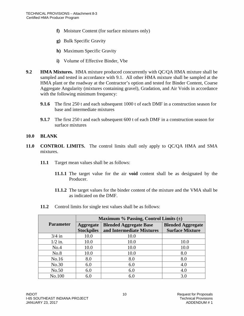
TECHNICAL PROVISIONS – Attachment 8-3 Certified HMA Producer Program
INDOT 10 Request for Proposals I-65 SOUTHEAST INDIANA PROJECT Technical Provisions JANUARY 23, 2017 ADDENDUM # 1
f) Moisture Content (for surface mixtures only)
g) Bulk Specific Gravity
h) Maximum Specific Gravity
i) Volume of Effective Binder, Vbe 9.2 HMA Mixtures. HMA mixture produced concurrently with QC/QA HMA mixture shall be
sampled and tested in accordance with 9.1. All other HMA mixture shall be sampled at the HMA plant or the roadway at the Contractor’s option and tested for Binder Content, Coarse Aggregate Angularity (mixtures containing gravel), Gradation, and Air Voids in accordance with the following minimum frequency:
9.1.6 The first 250 t and each subsequent 1000 t of each DMF in a construction season for
base and intermediate mixtures
9.1.7 The first 250 t and each subsequent 600 t of each DMF in a construction season for surface mixtures
10.0 BLANK 11.0 CONTROL LIMITS. The control limits shall only apply to QC/QA HMA and SMA
mixtures.
11.1 Target mean values shall be as follows:
11.1.1 The target value for the air void content shall be as designated by the Producer.
11.1.2 The target values for the binder content of the mixture and the VMA shall be
as indicated on the DMF.
11.2 Control limits for single test values shall be as follows:
Parameter Maximum % Passing, Control Limits (±)
Aggregate Stockpiles
Blended Aggregate Base and Intermediate Mixtures
Blended Aggregate Surface Mixture
3/4 in 10.0 10.0 1/2 in. 10.0 10.0 10.0 No.4 10.0 10.0 10.0 No.8 10.0 10.0 8.0 No.16 8.0 8.0 8.0 No.30 6.0 6.0 4.0 No.50 6.0 6.0 4.0 No.100 6.0 6.0 3.0

TECHNICAL PROVISIONS – Attachment 8-3 Certified HMA Producer Program
INDOT 11 Request for Proposals I-65 SOUTHEAST INDIANA PROJECT Technical Provisions JANUARY 23, 2017 ADDENDUM # 1
No.200 2.0 2.0 2.0 Parameter Control Limits
Binder Content of Mixture and RAP, % ± 0.7 Binder Content of RAS, % ± 3.0 VMA @ Ndes, % (QC/QA HMA) ± 1.0 VMA @ N75, Minimum % (9.5 mm SMA) 17.0 VMA @ N75, Minimum % (12.5 mm SMA) 16.0 Target Air Voids % (Dense Graded Mixtures, SMA) ± 1.0 Target Air Voids % (Open Graded Mixtures) ± 3.0
12.0 RESPONSE TO TEST RESULTS.
12.1 The Producer shall take corrective action when the control limits for QC/QA HMA and SMA or specification limits for HMA Mixtures are exceeded for the appropriate properties of Mixture Binder Content, Air Voids, or VMA.
12.2 The Producer shall document the action taken to restore the 2.36 mm sieve %
passing gradation for a 9.5 mm HMA surface mixture when it is determined to be greater than the PCS control point value of 47%.
12.3 The Producer shall document the action taken to restore the aggregate degradation
value for SMA mixture in accordance with ITM 220 when it is determined to be greater than 3.0%.
12.4 The Producer shall document the action taken to restore the dust/calculated effective
binder ratio when it is determined to be greater than 1.4. 12.5 The Producer shall document the action taken to restore the volume of effective
binder, Vbe, when it is determined to be less than the design minimum as follows:
Mixture Designation Minimum Vbe, % 9.5 mm SMA 13.0 12.5 mm SMA 12.0
4.75 mm 12.0 9.5 mm 11.0 12.5 mm 10.0 19.0 mm 9.0 25.0 mm 8.0
12.6 Moisture Content. The Producer shall take corrective action when the
moisture content of the mixture sampled at the HMA Plant exceeds 0.30 percent or when the moisture content of the surface mixture sampled from the pavement exceeds 0.10 percent.

TECHNICAL PROVISIONS – Attachment 8-3 Certified HMA Producer Program
INDOT 12 Request for Proposals I-65 SOUTHEAST INDIANA PROJECT Technical Provisions JANUARY 23, 2017 ADDENDUM # 1
12.7 The Producer in-line blending SBR latex at the HMA plant shall take corrective action if the latex solids content is more than 0.2% below the lower target limit for more than 15 minutes of production.
12.8 Documentation. All corrective action shall be documented in the diary.
13.0 QUALITY CONTROL PLAN.
13.1 Each Producer providing mixture under the Program shall have a written QCP which shall be HMA plant specific and be the basis of control. The QCP shall contain, but not be limited to, the methods of sampling, testing, calibration, verification, inspection, and anticipated frequencies.
13.2 If applicable, the QCP shall include the following information for each HMA Plant:
13.2.1 The location of the HMA Plant site, including the county and reference to
the nearest identifiable points such as highways and towns.
13.2.2 The name, telephone number, fax number, email address, duties, and employer of the Management Representative, Certified Asphalt Technician(s), and Qualified Technician(s), if applicable. The duties of all other personnel responsible for implementation of the QCP shall be included.
13.2.3 A list of test equipment that is calibrated or verified, the test methods and
frequency of calibration or verification of the equipment, and a statement of accessibility of the laboratory to Department personnel.
If the laboratory is not located at the HMA Plant, the location of the laboratory shall be designated, and the procedure for transporting the mixture to the laboratory included.
13.2.4 A HMA plant site layout diagram which shall include the location of the
stockpile area, binder tanks, fuel tank, fiber supply, anti-adhesive supply, field laboratory, visitor parking area, and major components of the mixing HMA plant.
13.2.5 A plan for controls of the aggregate and recycled material stockpiles.
Controls for identification of stockpiles by signing or other acceptable methods, techniques for construction of proper stockpiles, and cold bin loading procedures to prevent overflow of material from one bin into another shall be included.

TECHNICAL PROVISIONS – Attachment 8-3 Certified HMA Producer Program
INDOT 13 Request for Proposals I-65 SOUTHEAST INDIANA PROJECT Technical Provisions JANUARY 23, 2017 ADDENDUM # 1
13.2.6 A plan for the identification of the grade of binder in each storage tank and the use of more than one binder grade in a binder tank. The sampling location shall be indicated.
13.2.7 A plan for in-line blending SBR polymer latex at the HMA plant to include
a QCP in accordance with ITM 581 as an addendum to the plant QCP
13.2.8 A plan for the production of HMA produced with a water-injection foaming device. The necessary plant modifications, plant production start-up process, planned mixture production temperature ranges, and moisture testing on mixtures sampled at the plant for each DMF shall be included.
13.2.9 The procedure for the consistent uniform addition of baghouse fines when
returned into the HMA plant.
13.2.10 The procedure for the consistent uniform addition of fibers into the HMA plant.
13.2.11 The procedure for using an anti-adhesive agent for the truck bed, and a
statement that the agent is on the Department’s List of Approved Anti-Adhesive Materials.
13.2.12 The procedure for sealing the surge bin when used for extended storage of
the mixture up to one working day, and the method to prevent the discharge when the mixture falls below the top of the cone.
13.2.13 The procedure for loading mixture into the trucks.
13.2.14 A sampling plan that includes locations, test methods, devices, techniques,
frequencies, and sample reduction procedures.
13.2.15 A testing plan that includes the types of tests, and test methods. 13.2.16 A description of any other process control techniques that may be used.
These controls may include, but are not limited to:
a) Different types of material testing
b) Visual checks, and monitoring of HMA plant production
13.2.17 A statement of the procedure for handling addenda to the QCP including a time schedule for submittal.
13.2.18 A documentation plan with details on control charting, test data, and the
diary. Copies of the forms may be included.

TECHNICAL PROVISIONS – Attachment 8-3 Certified HMA Producer Program
INDOT 14 Request for Proposals I-65 SOUTHEAST INDIANA PROJECT Technical Provisions JANUARY 23, 2017 ADDENDUM # 1
13.3 The last page of the QCP shall contain two signatures. One signature shall be the Producer Management Representative. The date of submittal and the corporate title of the Producer Management Representative making the signature shall be included. The other signature shall be for approval by the Manager, Office of Materials Management.
13.4 Production of mixture shall not begin before the QCP has been approved. The
Producer shall submit two copies of the QCP to the Department for review. One copy shall be submitted to the District Testing Engineer, and one copy to the Office of Materials Management. Acceptance or rejection of the QCP will be made within 15 days of receipt of the QCP. One approved copy will be returned to the Producer.
13.5 The Producer shall transmit all applicable process control changes to the District
Testing Engineer for approval. This shall be done in the format of addenda to the QCP. Each page of the QCP that is revised shall include the HMA plant number, date of revision, and means of identifying the revision. The addenda shall be signed and dated by the Management Representative and subsequently signed and dated when approved by the District Testing Engineer.
Revisions for HMA plant major components, Certified Asphalt Technicians, and movement of the HMA plant shall be submitted in the format of a QCP Annex as they occur, and upon approval by the District Testing Engineer shall be included in the Appendix of the QCP. Revisions, other than items on the QCP Annex, shall be maintained on the Addenda Summary sheet in the QCP Appendix.
Addenda may be submitted at the audit close-out meeting or within the first two months of each calendar year. The addenda shall include items on the QCP Annex, items on the Addenda Summary Sheet, and any other necessary revisions at the time of submittal. Upon incorporation into the QCP as addenda, the QCP Annex and items on the Addenda Summary Sheet shall be removed from the QCP Appendix.
13.6 Movement of the HMA Plant to a new location will require an addendum to the
QCP. Verification of the calibration of all meters, scales and other measuring devices in accordance with 14.3 shall be completed.
14.0 CERTIFICATION.
14.1 Each Producer requesting to establish a Certified Plant shall do so in writing to the Manager, Office of Materials Management.
14.2 Upon receipt of the request for certification, the District Testing Engineer will be
notified to inspect the plant and laboratory. 14.3 A plant inspection, including the correction of any deficiencies and calibration of all
meters, scales and other measuring devices to an accuracy within 0.5% throughout their range, shall be completed prior to certification.

TECHNICAL PROVISIONS – Attachment 8-3 Certified HMA Producer Program
INDOT 15 Request for Proposals I-65 SOUTHEAST INDIANA PROJECT Technical Provisions JANUARY 23, 2017 ADDENDUM # 1
14.4 Each HMA plant meeting the requirements of the Program will be certified upon the
approval of the QCP. 14.5 The Producer, in accordance with ITM 581, shall submit a written request to the
Asphalt Engineer, Office of Materials Management, to in-line blend SBR polymer latex at the HMA plant.
14.6 In the event of a change in ownership of the Certified HMA Plant, the certification
shall expire on the date of such change. The new ownership may avoid expiration by submitting a statement to the Manager, Office of Materials Management indicating recognition of the details of the Program, the existing QCP, and a clear pronouncement of intent to operate in accordance with the requirements of both documents prior to providing mixture for the Program.
15.0 DEPARTMENT RESPONSIBILITIES.
15.1 The Department will conduct annual audits on a random basis of each HMA Plant.
15.2 The Department will maintain the List of Approved Certified Hot Mix Asphalt Producers. Producers meeting the requirements of the ASC program for in-line blending of SBR polymer latex will be indicated as a Performance-Graded Asphalt Binder Approved Supplier on the List.
15.3 The Department will administer a Certified Asphalt Technician Training Program
for those Asphalt Technicians that perform the required duties for the Certified HMA Plant. Certification of the Technicians will be provided by the Department upon passing a certification test and becoming a Qualified Technician for the test methods designated in the Certified Asphalt Technician Program Procedures and Policies Manual.
15.4 The removal of a Producer from the Department’s List of Approved Certified Hot
Mix Asphalt Producers will be the responsibility of the Office of Materials Management. The Producer shall have the right to appeal the removal from the Department’s List of Approved Certified Hot Mix Asphalt Producers to the Director, Construction Management Division.
HMA QCP ANNEX
Company ___________________________________________________ Plant No. ______________ PLANT MAJOR COMPONENT REVISION

TECHNICAL PROVISIONS – Attachment 8-3 Certified HMA Producer Program
INDOT 16 Request for Proposals I-65 SOUTHEAST INDIANA PROJECT Technical Provisions JANUARY 23, 2017 ADDENDUM # 1
Revision: _____________________________________________________________________ ________________________________________________________________________ ________________________________________________________________________ CERTIFIED ASPHALT TECHNICIAN REVISION Delete Technician from QCP ______________________________________________________ Add Technician to QCP ______________________________________________________ PLANT MOVEMENT Existing Location: ______________________________________________________________ ________________________________________________________________________ New Location: _________________________________________________________________ ________________________________________________________________________ ________________________________________________________________________ _____________________ ________ ______________________ _______ District Testing Engineer Date Management Representative Date
INDIANA DEPARTMENT OF TRANSPORTATION
HOT MIX ASPHALT (HMA) TYPE D CERTIFICATION CONTRACT NUMBER _________________ DATE____________ CERTIFIED HMA PRODUCER ______________________________________________________________ CERTIFIED HMA PLANT NUMBER _____________ DMF NUMBER ________________

TECHNICAL PROVISIONS – Attachment 8-3 Certified HMA Producer Program
INDOT 17 Request for Proposals I-65 SOUTHEAST INDIANA PROJECT Technical Provisions JANUARY 23, 2017 ADDENDUM # 1
PG BINDER SOURCE _______________ PG BINDER GRADE________________ MIXTURE TYPE AND SIZE ________________________________________________________________ DESIGN ESAL __________________ Air Voids _________ (from DMF) Binder Content _________ (from DMF) This is to certify that the test results for Air Voids and Binder Content represent the HMA mixture supplied to this contract. Air Voids ______ (± 1.5 % from DMF) Binder Content _______ (± 0.7% from DMF) * [ ] Test results are not available for submittal. A production sample shall be taken within the first 250 t (250 Mg) and each subsequent 1000 t (1000 Mg) for base and intermediate mixtures and each subsequent 600 t (600 Mg) for surface mixtures. * If Applicable __________________________________________ Signature of HMA Producer Official __________________________________________ Title of Official FOR PE/PS USE ONLY PAY ITEM(S) _____________________________________ BASIS FOR USE NO. C999998 SPECIFICATION REFERENCE __ 304.04 - Patching __ 402.07(c) - Temporary HMA __ 610 - Approaches __ 304.05 - Widening __ 503.03(e) - Terminal Joints __ 610 - Crossovers __ 402.04 - HMA Pavements __ 507.05(b) - Partial Depth Patching __ 718.04 - Underdrains __ 402.07(a) - Rumble Strips __ 604.07(c) – Sidewalk __ 801.11- Temp. Crossovers __ 402.07(b) - Wedge & Leveling __ 605.07(c) – Curbing

TECHNICAL PROVISIONS – Attachment 8-3 Certified HMA Producer Program
INDOT 18 Request for Proposals I-65 SOUTHEAST INDIANA PROJECT Technical Provisions JANUARY 23, 2017 ADDENDUM # 1
INDIANA DEPARTMENT OF TRANSPORTATION OFFICE OF MATERIALS MANAGEMENT
DELTA Pb (ΔPb) DETERMINATION
FOR DENSE GRADED HMA OR SMA MIXTURES
ITM No. 591-16T 1.0 SCOPE.
1.1 This test method covers the procedure to determine the delta Pb, (ΔPb), which is the difference between the estimated total binder content of the mixture, (Pb)EST, and the total binder content as reported on the DMF, (Pb)DMF.
The (Pb)EST is derived from the effective binder content of the mixture, Pbe, and an estimate of asphalt binder absorption, (Pba)EST.
1.2 The ΔPb determination begins by obtaining the aggregate bulk specific gravity list
and instructions as well as any applicable addendums. The mixture type, the aggregate and recycled materials blend percentages, the total binder content and the mixture bulk specific gravity value must also be obtained from the DMF mix-design cover sheet.
1.3 This ITM may involve hazardous materials, operations, and equipment and may not
address all of the safety problems associated with the use of the test method. The user of the ITM is responsible for establishing appropriate safety and health practices and determining the applicability of regulatory limitations prior to use.
2.0 REFERENCED DOCUMENTS.
2.1 AASHTO Standards.
R 35 Superpave Volumetric Design for Hot Mix Asphalt R 46 Designing Stone Matrix Asphalt (SMA)
2.2 ITM Standards.
584 Bulk Specific Gravity of Aggregate Blends with Recycled Aggregate
2.3 Other References. SP-2 Superpave Mix Design by Asphalt Institute Design Mix Formula Cover Sheet 3.0 TERMINOLOGY. Definitions for terms and abbreviations shall be in accordance with the
Department’s Standard Specifications, Section 101.

TECHNICAL PROVISIONS – Attachment 8-3 Certified HMA Producer Program
INDOT 19 Request for Proposals I-65 SOUTHEAST INDIANA PROJECT Technical Provisions JANUARY 23, 2017 ADDENDUM # 1
4.0 SIGNIFICANCE AND USE. This test method covers the procedure to determine the ΔPb
which is the difference between the (Pb)EST and (Pb)DMF. 5.0 APPARATUS. The apparatus shall be as stated in the referenced test methods. 6.0 SAMPLING. Sampling shall be as stated in the referenced test methods. 7.0 PROCEDURE.
7.1 Determine the water absorption of the combined aggregates blend as follows: (ABS)TOTAL = (ABS1)(P1) + (ABS2)(P2) + … + (ABSN)(PN) + (1.00)[(PRAP) + (PRAS)
+ (PBH) + (PMF)] W(ABS)TOTAL=(ABS1)(P1)+(ABS2)(P2)+…+(ABSN)(PN)+(1.000)[(PRAP)+(PRAS)+(PBH)]here:
• (ABS)TOTAL = water absorption of the combined aggregates blend • P1, P2…PN = percentages by weight of aggregates 1, 2…N as shown on the
DMF cover sheet • ABS1, ABS2…ABSN = water absorption of aggregates 1, 2…N • PRAP, PRAS, PBH, PMF = percentages by weight of RAP, RAS, Baghouse Fines
and Mineral Filler as shown on the DMF cover sheet • P1 + P2 + … + PN + PRAP + PRAS + PBH + PMF = 100.0%
7.2 Determine the estimated total binder content as follows:
( )
+
+=
100(Pba) 1
(Pba) (Pbe) PbEST
ESTEST
Where:
=
1.03Gmb
4.0) -(*VMA (Pbe) *use the specification minimum VMA value
(Pba)EST = (0.50) x (ABS)TOTAL when (ABS)TOTAL < 1.25% (Pba)EST = (0.65) x (ABS)TOTAL when 1.25% ≤ (ABS)TOTAL ≤ 2.50% (Pba)EST = (0.80) x (ABS)TOTAL when (ABS)TOTAL > 2.50%
7.3 Determine the ΔPb as follows: ΔPb = (Pb)EST – (Pb)DMF

TECHNICAL PROVISIONS – Attachment 8-3 Certified HMA Producer Program
INDOT 20 Request for Proposals I-65 SOUTHEAST INDIANA PROJECT Technical Provisions JANUARY 23, 2017 ADDENDUM # 1
8.0 REPORT. The ΔPb value is reported to the nearest 0.01.
INDOT Request for Proposals I-65 SOUTHEAST INDIANA PROJECT Page-1 Technical Provisions JANUARY 23, 2017 ADDENDUM # 1
ATTACHMENT 8-4
ADDITIONAL SPECIFICATIONS
A. PCCP Joints………………………………………………………………….…….2 B. Concrete Pavement QC/QA………………………………….…………..5 C. QC/QA-HMA, 4, 64, Intermediate, OG 9.5 mm…………......9 D. Course Aggregate, No. 43, Base………………………..10

INDOT Request for Proposals I-65 SOUTHEAST INDIANA PROJECT Page-2 Technical Provisions JANUARY 23, 2017 ADDENDUM # 1
PCCP JOINTS
The Standard Specifications are revised as follows:
SECTION 503, DELETE LINE 16, INSERT AS FOLLOWS: Hot Pour Joint Material............. 906 02(a)2
SECTION 503, BEGIN LINE 49, DELETE AND INSERT AS FOLLOWS:
Sawed contraction joints shall be cut in two operations. The initial saw cut shall SECTION 503, BEGIN LINE 59, DELETE AND INSERT AS FOLLOWS:
The second saw cut shall be made after the concrete has sufficiently cured, but before opening the pavement to non-construction traffic. The width of the saw cut shall be measured for specification compliance at the time of the sawing operations Slurry or saw residue
SECTION 503, BEGIN LINE 78, DELETE AND INSERT AS FOLLOWS: construction traffic uses the PCCP prior to sealing. The sawed joint shall be cleaned as specified in 503 05(a)
SECTION 503, BEGIN LINE 214, DELETE AS FOLLOWS:
When preformed elastomeric joint seals are used, the material shall be installed in one continuous piece by means of an approved machine. The seal shall not be stretched more than 5% while being placed and show no twisting, rollover, folding, cutting, or excess lubricant-adhesive on the top of the seal. Elastomeric joint seal may be installed in two separate pieces for phased construction with the splice point occurring at the highest point of the joint. The splicing method used shall be in accordance with the seal manufacturer's recommendations.

INDOT Request for Proposals I-65 SOUTHEAST INDIANA PROJECT Page-3 Technical Provisions JANUARY 23, 2017 ADDENDUM # 1

INDOT Request for Proposals I-65 SOUTHEAST INDIANA PROJECT Page-4 Technical Provisions JANUARY 23, 2017 ADDENDUM # 1

INDOT Request for Proposals I-65 SOUTHEAST INDIANA PROJECT Page-5 Technical Provisions JANUARY 23, 2017 ADDENDUM # 1
Quality Control/ Quality Assurance, QC/QA, Portland Cement Concrete Pavement, PCCP
SECTION 501.03, AFTER LINE 32 INSERT THE FOLLOWING:
Silica fume...........................................................................901 04
SECTION 501.04(a), LINE 48, DELETE AND INSERT AS FOLLOWS:
(g) the specific gravity of pozzolan each supplementary cementitious material (SCM)
SECTION 501.04(a), LINE 68, DELETE AND INSERT AS FOLLOWS:
2. pozzolan SCM source or type SECTION 501.04(b), LINES 95 & 96, DELETE AS FOLLOWS:
6. increase in cement content from the amount designated in the original CMDP.
SECTION 501.05, LINES 117-125 DELETE AND INDERT AS FOLLOWS:
The CMD shall contain at least one, but no more than two SCM's, and produce workable concrete mixtures having the following properties:
Minimum portland total cement cementitious content defined by CMDP.......400 500
lbs/cu yd Allowable amount of single SCM defined by CMDP, % of total cementitious, by weight 20 0
- 40 0%* Allowable amount of two SCM's defined by CMDP, % of total cementitious, by weight 25 0
- 40 0%** Minimum portland cement content defined by CMDP.............350 lbs/cu
yd Allowable amount of silica fume SCM defined by CMDP, % of total cementitous
content. 3 0 - 7 0% Maximum allowable water/cementitious ratio of concrete mixture with fly ash SCM ...0.450 0 440

INDOT Request for Proposals I-65 SOUTHEAST INDIANA PROJECT Page-6 Technical Provisions JANUARY 23, 2017 ADDENDUM # 1
Maximum allowable water cementitious ratio of concrete mixture with ggbfs SCM.....0 450
Minimum portland cement/fly ash ratio ......................3.2 by weight Minimum portland cement/GGBFS ratio ....................2.3 by weight Target air content defined by CMDP .................................. 6.5 7 0% Minimum flexural strength, third point loading .....570 psi at 7 days
*For binary binder system that contains fly ash or ggbfs combined with cement
**For ternary mixes, the amount of fly ash or ggbfs in the binder system shall not be less than
15 0% of the total cementitious defined by the CMDP Silica fume may be a SCM component of a ternary binder system
SECTION 501.05, LINES 146 TO 151, DELETE AND INSERT THE FOLLOWING:
Fly ash or GGBFS used as an additive, or blended cements may only be incorporated in the concrete mix between April 1 and October 15 of the same calendar year. If type IP, type IP-A, type IS or type IS-A cements are to be used, the minimum portland cement content shall be increased to 500 lbs/cu yd. The use of fly ash or GGBFS as an additive will not be allowed when blended cement types IP, IP-A, IS, or IS-A are used. SCM's may be used in concrete for slip- form paving operations without calendar restriction If a Type IP, IP-A, IS, or ISA blended cement is used in the concrete, the additional use of a SCM, other than silica fume, is not allowed
In formed paving operations, fly ash or ggbfs SCM's may only be used in concrete that is placed between April 1 and October 15 of the same calendar year
Silica fume SCM may be used in slip-formed and formed PCCP without calendar restriction If a Type IP, IP-A, IS of ISA blended cement is used in the concrete, the additional use of a
SCM, other than silica fume, is not allowed SECTION 501.06, LINES 166 – 169, DELETE AND INSERT THE FOLLOWING: conduct the air content test. The air content shall be 5.0 5 5% to 10.0%. The plastic unit weight shall be within ± 3.0% from the target plastic unit weight of the CMDS. The water/cementitious ratio shall be within ± 0.030 0 015 of the target value of the CMDS and shall not exceed 0.450 the maximum amount allowed for the appropriate mix in accordance with 501 05. The flexural strength shall be determined by averaging a
SECTION 501.15, LINES 288-289, DELETE AND INSERT THE FOLLOWING:

INDOT Request for Proposals I-65 SOUTHEAST INDIANA PROJECT Page-7 Technical Provisions JANUARY 23, 2017 ADDENDUM # 1
when the ambient temperature is 35°F and above, unless procedures outlined in the QCP for lower temperatures are followed. If the local forecast predicts an average minimum temperature below 40 °F for 10 consecutive days, the QCP shall provide details prior to the cold weather to address changes in materials, concrete batching and mixing processes, construction methods, curing, and protection of the in situ concrete to insure that the necessary quality characteristics will not be compromised as a result of the cold weather Prior to attaining opening to traffic
SECTION 501.23(a). LINES 356-357, DELETE AND INSERT THE FOLLOWING:
Construction vehicles or equipment will be allowed on the PCCP after 10 days or when flexural tests indicate a modulus of rupture of 550 psi or greater. ITM 402 SECTION 501.23(b), LINES 364-367, DELETE AND INSERT THE FOLLOWING:
The PCCP may be opened to traffic after 14 days. The PCCP may be opened earlier if the test beams of ITM 402 when flexural tests indicate a modulus of rupture of 550 psi or greater. ITM 402 may be used as an alternate method to determine the flexural strength If adequate strengths are not met within 14 days achieved, an investigation by the Engineer and Contractor will be conducted to determine if the PCCP is deficient. Resolutions for
SECTION 501.27(b), LINE 518, DELETE AND INSERT THE FOLLOWING:
0.030 of the target value or exceed 0.450 the maximum allowed for the appropriate mixture in accordance with 501 05. A stop paving order will be issued if the
SECTION 501.27(d), LINES 533 – 534, DELETE AND INSSERT THE FOLLOWING:
The average lot air content values shall not vary more than - 0.8 1 2% to + 2.4 2 2% from the 6.5 7.0% target air content. The range of sublot air content values shall not SECTION 501.28(b)1., LINE 606, DELETE AND INSERT THE FOLLOWING:

INDOT Request for Proposals I-65 SOUTHEAST INDIANA PROJECT Page-8 Technical Provisions JANUARY 23, 2017 ADDENDUM # 1
LOT AVERAGE AIR CONTENT Percent, % Pay Factors
> 9.8 * 9.7 - 9.8 0.80 0 85 9.5 - 9.6 0.90 0 95 9.3 - 9.4 0.95 0 99
9.0 5 8 - 9.2 0.99 1 00 5.7 - 8.9 1.00 0 93
5.6 0.93 0 90 5.5 0.90 0 85 5.4 0.85 0 79 5.3 0.79
< 5.3 5 4 * * The PCCP will be adjudicated as a failed material in accordance
with normal Department practice as listed in 105.03. The PCCP may be subject to removal and replacement or left in place with reduced or no payment.
LOT RANGE FOR AIR CONTENT
Percent, % Pay Factors 0.0 - 2.5 1.00 2.6 - 3.0 0.99 3.1 - 3.5 0.97
> 3.5 * * The PCCP will be adjudicated as a failed material in accordance
with normal Department practice as listed in 105.03. The PCCP may be subject to removal and replacement or left in place with reduced or no payment.
SECTION 501.28(b)2., LINE 609, DELETE AND INSERT THE FOLLOWING: If a sublot value is less than 5.0 5 5% or greater than 10.0%, the PCCP will be

INDOT Request for Proposals I-65 SOUTHEAST INDIANA PROJECT Page-9 Technical Provisions JANUARY 23, 2017 ADDENDUM # 1
QC/QA-HMA, 4, 64, INTERMEDIATE, OG 9.5 mm
The OG 9.5 mm intermediate mixture shall be in accordance with 401 for use as a bond breaking layer for a PCCP overlay. The OG 9.5 mm intermediate volumetric mix design shall be in accordance with 401.05 with the following exceptions:
1. The single percentage of aggregate passing each required sieve shall be within the following limits: 12.5 mm sieve (100% passing); 9.5 mm sieve (75.0% – 100% passing); 4.75 mm sieve (10.0% – 35.0% passing); 2.36 mm sieve (0 – 15.0% passing) and 75 micron sieve (0 – 6.0% passing).
2. The optimum binder content for dense graded mixtures shall produce between 10.0% - 15.0% air voids at Ndes = 20 gyrations.
3. VMA and VFA shall not be applicable.
The finished thickness of this mixture shall be at least 1.5 times but not more than 6 times the maximum particle size as shown on the DMF or JMF. Feathering may be less than the minimum thickness requirements. All pavement smoothness requirements from 401.18 are waived for this HMA mixture.

INDOT Request for Proposals I-65 SOUTHEAST INDIANA PROJECT Page-10 Technical Provisions JANUARY 23, 2017 ADDENDUM # 1
COARSE AGGREGATE, NO. 43, BASE
Description This work shall consist of furnishing and placing a coarse aggregate base to serve as a drainage layer.
Materials Coarse Aggregate, No. 43, Base shall be in accordance with 904.
Construction Requirements The construction requirements shall be in accordance with 301, except that in order to prevent segregation, the use of a spreader box to place the base is required. The transportation, placing, compacting, and all necessary incidentals are included in the fixed price. Compaction shall be in accordance with 302.6 (b).
Method of Measurement The coarse aggregate base will be measured in accordance with 301.

INDOT Request for Proposals I-65 SOUTHEAST INDIANA PROJECT Technical Provisions JANUARY 23, 2017 ADDENDUM # 1
ATTACHMENT 8-5
PATCHING LOCATIONS

TECHNICAL PROVISIONS - Attachment 8-5 Patching Locations
INDOT Request for Proposals I-65 SOUTHEAST INDIANA PROJECT Technical Provisions JANUARY 23, 2017 1 ADDENDUM # 1
PATCHING WORKSHEET
NORTHBOUND I-65 PATCHING TABLE
STA. DIR. LANE TYPE WIDTH LENGTH
Partial Depth PCCP
Full Depth PCCP
D-1 CONTR. JOINT
RETROFIT TIE BARS
(FT) (FT) (SYS) (SYS) (LFT) (LFT) 2411+14 NB Passing Partial 0.83 2 0.19 2411+29 NB Passing Partial 0.83 2 0.19 2411+74 NB Passing Partial 0.83 2 0.19 2412+03 NB Passing Partial 0.83 1 0.09 2412+63 NB Passing Partial 1.00 4 0.44 2412+78 NB Passing Partial 1.00 2 0.22 2413+09 NB Passing Partial 0.83 2 0.19 2413+23 NB Passing Partial 1.00 2 0.22 2413+38 NB Passing Partial 0.83 2 0.19 2413+53 NB Passing Partial 1.00 4 0.44 2413+68 NB Passing Partial 0.83 1 0.09 2413+83 NB Passing Partial 1.00 2 0.22 2414+13 NB Passing Partial 1.00 1 0.11 2414+28 NB Passing Partial 1.00 1 0.11 2414+43 NB Passing Partial 1.00 1 0.11 2432+92 NB Driving Full 14 6 9.33 2433+46 NB Passing Partial 0.83 1 0.09 2436+69 NB Driving Full 14 6 9.33 2437+42 NB Passing Partial 0.83 1 0.09 2437+59 NB Passing Partial 0.83 1 0.09 2437+64 NB Driving Full 12 10 13.33 2438+43 NB Driving Full 12 10 13.33 2438+98 NB Driving Full 14 6 9.33 2439+87 NB Both Full 26 6 17.33 2441+22 NB Both Partial 1.00 1 0.11 2442+21 NB Both Full 26 6 17.33 2442+39 NB Driving Full 14 6 9.33 2442+58 NB Driving Full 14 6 9.33 2442+74 NB Driving Full 12 12 16.00 2442+78 NB Passing Full 12 6 8.00 2443+05 NB Passing Partial 0.83 1 0.09 2443+58 NB Both Full 12 6 8.00 2443+76 NB Passing Partial 0.83 1 0.09 2443+85 NB Both Full 26 6 17.33 2444+42 NB Passing Full 12 6 8.00

TECHNICAL PROVISIONS - Attachment 8-5 Patching Locations
INDOT Request for Proposals I-65 SOUTHEAST INDIANA PROJECT Technical Provisions JANUARY 23, 2017 2 ADDENDUM # 1
PATCHING WORKSHEET (continued)
NORTHBOUND I-65 PATCHING TABLE
STA. DIR. LANE TYPE WIDTH LENGTH
Partial Depth PCCP
Full Depth PCCP
D-1 CONTR. JOINT
RETROFIT TIE BARS
(FT) (FT) (SYS) (SYS) (LFT) (LFT) 2444+61 NB Passing Full 12 6 8.00 2444+67 NB Driving Full 12 12 16.00 2444+98 NB Passing Full 12 6 8.00 2445+68 NB Passing Full 12 6 8.00 2445+68 NB Driving Full 12 24 32.00 24 8 2445+97 NB Driving Full 14 6 9.33 2446+61 NB Both Full 26 6 17.33 2446+77 NB Both Full 26 6 17.33 2447+79 NB Both Partial 0.83 2 0.19 2447+89 NB Both Full 26 6 17.33 2448+04 NB Both Full 26 6 17.33 2448+23 NB Driving Full 14 6 9.33 2448+70 NB Both Partial 0.83 2 0.19 2449+49 NB Both Full 26 6 17.33 2451+12 NB Both Full 26 6 17.33 2451+28 NB Both Full 26 6 17.33 2452+49 NB Passing Partial 0.83 1 0.09 2452+58 NB Driving Full 14 6 9.33 2452+76 NB Both Full 26 6 17.33 2452+92 NB Both Full 26 6 17.33 2453+11 NB Both Full 26 6 17.33 2453+29 NB Both Full 26 6 17.33 2453+47 NB Both Full 26 6 17.33 2453+67 NB Driving Full 14 6 9.33 2454+37 NB Both Full 26 6 17.33 2454+56 NB Passing Full 12 6 8.00 2454+76 NB Both Full 26 6 17.33 2454+87 NB Passing Partial 0.83 1 0.09 2455+59 NB Driving Partial 0.83 1 0.09 2455+76 NB Passing Partial 2.00 1 0.22 2455+83 NB Both Full 26 6 17.33 2456+40 NB Both Full 26 6 17.33 2457+12 NB Both Full 26 6 17.33 2457+31 NB Both Full 26 6 17.33 2457+86 NB Both Full 26 6 17.33

TECHNICAL PROVISIONS - Attachment 8-5 Patching Locations
INDOT Request for Proposals I-65 SOUTHEAST INDIANA PROJECT Technical Provisions JANUARY 23, 2017 3 ADDENDUM # 1
PATCHING WORKSHEET (continued)
NORTHBOUND I-65 PATCHING TABLE
STA. DIR. LANE TYPE WIDTH LENGTH
Partial Depth PCCP
Full Depth PCCP
D-1 CONTR. JOINT
RETROFIT TIE BARS
(FT) (FT) (SYS) (SYS) (LFT) (LFT) 2458+13 NB Passing Partial 0.83 1 0.09 2459+23 NB Both Partial 0.83 1 0.09 2459+34 NB Both Full 26 6 17.33 2460+26 NB Both Full 26 6 17.33 2461+19 NB Passing Full 12 6 8.00 2469+29 NB Passing Partial 0.83 1 0.09 2478+76 NB Passing Partial 2.00 1 0.22 2479+04 NB Driving Full 12 40 53.33 36 13 2480+86 NB Driving Full 12 40 53.33 36 13 2484+70 NB Both Full 24 6 16.00 2485+22 NB Driving Full 12 22 29.33 12 7 2485+50 NB Driving Partial 1.00 1 0.11 2485+69 NB Both Partial 0.83 4 0.37 2492+23 NB Driving Partial 0.83 4 0.37 2492+79 NB Driving Partial 0.83 4 0.37 2493+04 NB Driving Partial 0.83 4 0.37 2495+64 NB Driving Full 12 6 8.00 2496+08 NB Passing Full 12 6 8.00 2496+26 NB Passing Full 12 6 8.00 2497+80 NB Driving Partial 0.83 4 0.37 2498+12 NB Driving Partial 0.83 4 0.37 2498+42 NB Passing Full 12 6 8.00 2499+31 NB Passing Full 12 6 8.00 2499+86 NB Driving Full 12 6 8.00 2500+22 NB Driving Full 12 6 8.00 2501+34 NB Driving Full 12 6 8.00 2501+53 NB Aux&Driving Full 20 8 17.78 2501+78 NB Driving Full 12 6 8.00 2501+96 NB Both Full 24 6 16.00 2502+53 NB Both Full 24 6 16.00 2502+72 NB Both Full 24 6 16.00 2502+90 NB Driving Full 12 6 8.00 2503+09 NB Driving Full 12 6 8.00 2503+28 NB Driving Full 12 6 8.00 2503+47 NB Both Full 24 6 16.00

TECHNICAL PROVISIONS - Attachment 8-5 Patching Locations
INDOT Request for Proposals I-65 SOUTHEAST INDIANA PROJECT Technical Provisions JANUARY 23, 2017 4 ADDENDUM # 1
PATCHING WORKSHEET (continued)
NORTHBOUND I-65 PATCHING TABLE
STA. DIR. LANE TYPE WIDTH LENGTH
Partial Depth PCCP
Full Depth PCCP
D-1 CONTR. JOINT
RETROFIT TIE BARS
(FT) (FT) (SYS) (SYS) (LFT) (LFT) 2503+67 NB Both Full 24 6 16.00 2503+84 NB Both Full 24 6 16.00 2504+02 NB Driving Full 12 6 8.00 2504+23 NB Both Full 24 6 16.00 2504+41 NB Both Full 24 6 16.00 2504+59 NB Both Full 24 6 16.00 2504+69 NB Driving Partial 0.83 4 0.37 2504+81 NB Both Full 24 6 16.00 2505+05 NB Both Full 24 6 16.00 2505+24 NB Driving Full 12 6 8.00 2505+44 NB Driving Full 12 6 8.00 2507+06 NB Passing Full 12 6 8.00 2507+24 NB Passing Full 12 6 8.00 2507+42 NB Passing Full 12 6 8.00 2508+15 NB Driving Full 12 6 8.00 2508+38 NB Driving Full 12 6 8.00 2508+57 NB Driving Full 12 6 8.00 2510+22 NB Driving Full 12 6 8.00 2510+41 NB Driving Full 12 6 8.00 2510+59 NB Driving Full 12 6 8.00 2510+75 NB Driving Full 12 6 8.00 2511+32 NB Driving Full 12 6 8.00 2511+50 NB Driving Full 12 6 8.00 2512+26 NB Driving Partial 0.83 4 0.37 2524+31 NB Passing Partial 0.83 4 0.37 2525+97 NB Passing Partial 0.83 1 0.09 2529+21 NB Driving Partial 0.83 1 0.09 2531+33 NB Passing Partial 0.83 1 0.09 2531+83 NB Passing Partial 0.83 12 1.11 2531+98 NB Passing Partial 0.83 12 1.11
SUBTOTAL 11 1216 108 41

TECHNICAL PROVISIONS - Attachment 8-5 Patching Locations
INDOT Request for Proposals I-65 SOUTHEAST INDIANA PROJECT Technical Provisions JANUARY 23, 2017 5 ADDENDUM # 1
PATCHING WORKSHEET (continued)
SOUTHBOUND I-65 PATCHING TABLE
STA. DIR. LANE TYPE WIDTH LENGTH
Partial Depth PCCP
Full Depth PCCP
D-1 CONTR. JOINT
RETROFIT TIE BARS
(FT) (FT) (SYS) (SYS) (LFT) (LFT) 2432+89 SB Passing Full 12 6 8.00 2412+41 SB Both Partial 0.83 4 0.37 2413+19 SB Both Partial 0.83 1 0.09 2413+99 SB Both Partial 0.83 1 0.09 2414+78 SB Both Partial 0.83 1 0.09 2415+59 SB Both Partial 0.83 2 0.19 2439+41 SB Passing Partial 0.83 1 0.09 2443+53 SB Both Full 26 6 17.33 2444+44 SB Passing Full 12 6 8.00 2446+97 SB Both Full 26 6 17.33 2447+14 SB Both Full 26 6 17.33 2447+31 SB Driving Full 14 6 9.33 2448+41 SB Driving Full 14 6 9.33 2448+95 SB Passing Full 12 6 8.00 2449+51 SB Both Full 26 6 17.33 2450+39 SB Both Full 26 6 17.33 2451+14 SB Both Full 26 6 17.33 2452+04 SB Both Full 26 6 17.33 2452+76 SB Passing Full 12 6 8.00 2453+47 SB Both Full 26 6 17.33 2453+66 SB Both Full 26 6 17.33 2454+41 SB Both Full 26 6 17.33 2455+13 SB Driving Full 14 6 9.33 2455+33 SB Passing Full 12 6 8.00 2455+33 SB Driving Full 14 12 18.67 2460+03 SB Both Full 26 6 17.33 2461+30 SB Passing Full 12 6 8.00 2461+87 SB Passing Full 12 6 8.00 2473+86 SB Driving Partial 0.83 2 0.19 2481+98 SB Driving Partial 0.83 2 0.19

TECHNICAL PROVISIONS - Attachment 8-5 Patching Locations
INDOT Request for Proposals I-65 SOUTHEAST INDIANA PROJECT Technical Provisions JANUARY 23, 2017 6 ADDENDUM # 1
PATCHING WORKSHEET (continued)
SOUTHBOUND I-65 PATCHING TABLE
STA. DIR. LANE TYPE WIDTH LENGTH
Partial Depth PCCP
Full Depth PCCP
D-1 CONTR. JOINT
RETROFIT TIE BARS
(FT) (FT) (SYS) (SYS) (LFT) (LFT) 2482+36 SB Driving Partial 0.83 3 0.28 2485+56 SB Both Full 26 6 17.33 2486+51 SB Both Full 26 6 17.33 2486+70 SB Both Full 26 6 17.33 2486+86 SB Driving Full 12 6 8.00 2487+25 SB Both Full 26 6 17.33 2487+44 SB Both Full 26 6 17.33 2487+99 SB Driving Full 12 6 8.00 2488+18 SB Driving Full 12 6 8.00 2489+52 SB Aux Partial 0.83 12 1.11 2489+93 SB Aux Partial 0.83 2 0.19 2490+03 SB Driving Full 12 6 8.00 2490+33 SB Aux Partial 0.83 1 0.09 2490+43 SB Driving Full 12 6 8.00 2492+43 SB Driving Full 12 6 8.00 2492+71 SB Aux Partial 0.83 1 0.09 2492+81 SB Driving Full 12 6 8.00 2493+03 SB Driving Full 12 6 8.00 2494+32 SB Driving Full 12 6 8.00 2494+74 SB Driving Partial 0.83 2 0.19 2494+80 SB Passing Partial 0.83 2 0.19 2495+17 SB Aux&Driving Partial 0.83 1 0.09 2496+63 SB Both Full 26 6 17.33 2496+93 SB Passing Full 12 6 8.00 2497+10 SB On Ramp Full 16 6 10.67 2497+21 SB Passing Partial 0.83 2 0.19 2503+56 SB Passing Partial 1.00 4 0.44 2504+22 SB Driving Full 12 6 8.00 2504+80 SB Driving Full 12 6 8.00 2505+34 SB Passing Full 12 6 8.00

TECHNICAL PROVISIONS - Attachment 8-5 Patching Locations
INDOT Request for Proposals I-65 SOUTHEAST INDIANA PROJECT Technical Provisions JANUARY 23, 2017 7 ADDENDUM # 1
PATCHING WORKSHEET (continued)
SOUTHBOUND I-65 PATCHING TABLE
STA. DIR. LANE TYPE WIDTH LENGTH
Partial Depth PCCP
Full Depth PCCP
D-1 CONTR. JOINT
RETROFIT TIE BARS
(FT) (FT) (SYS) (SYS) (LFT) (LFT) 2505+53 SB Driving Full 12 6 8.00 2505+91 SB Driving Full 12 6 8.00 2506+09 SB Both Full 26 6 17.33 2506+29 SB Both Full 26 6 17.33 2506+45 SB Both Full 26 6 17.33 2506+65 SB Both Full 26 6 17.33 2506+89 SB Passing Full 12 6 8.00 2506+89 SB Driving Partial 0.83 4 0.37 2507+06 SB Passing Full 12 6 8.00 2507+67 SB Both Full 26 6 17.33 2507+67 SB Aux Full 14 22 34.22 14 7 2507+83 SB Passing Full 12 6 8.00 2508+01 SB Passing Full 12 6 8.00 2508+58 SB Passing Full 12 6 8.00 2508+97 SB Both Partial 0.83 1 0.09 2510+74 SB Passing Full 12 6 8.00 2511+31 SB Aux Full 14 6 9.33 2513+14 SB Passing Full 12 6 8.00 2513+49 SB Passing Full 12 6 8.00 2516+92 SB Driving Full 14 6 9.33 2517+20 SB Both Partial 0.83 1 0.09 2518+03 SB Both Partial 0.83 2 0.19 2522+21 SB Driving Partial 0.83 4 0.37 2522+57 SB Passing Partial 0.83 2 0.19 2529+89 SB Driving Partial 0.83 1 0.09 2529+94 SB Both Partial 0.83 1 0.09
SUBTOTAL 6 731 14 7

TECHNICAL PROVISIONS – Attachment 9-1 UNIQUE SPECIAL PROVISIONS
INDOT Request for Proposals I-65 SOUTHEAST INDIANA PROJECT Technical Provisions JANUARY 23, 2017 ADDENDUM # 1
ATTACHMENT 9-1
UNIQUE SPECIAL PROVISIONS
Drainage
A. Cured-in-Place Thermosetting Resin Pipe Liner (CIPP)

TECHNICAL PROVISIONS – Attachment 9-1 Unique Special Provisions
INDOT Request for Proposals I-65 SOUTHEAST INDIANA PROJECT Technical Provisions JANUARY 23, 2017 1 ADDENDUM # 1
CURED-IN-PLACE THERMOSETTING RESIN PIPE LINER (CIPP)
Description This work shall consist of the fabrication, installation, and curing of
a tight-fitting, resin-impregnated fabric, cured-in-place pipe liner, hereinafter referred to as CIPP, into existing circular or deformed pipe structures in accordance with 105.03.
Materials CIPP shall be in accordance with ASTM D 5813, Type III, grade 1, 2, or
3, and shall be UV and abrasion resistant. The manufacturer shall determine the proper grade of the CIPP to be used under the installation and operation conditions that will exist for the location in which the CIPP is to be used. CIPP shall be designed in accordance with ASTM F 1216 and appendix X1 for a fully deteriorated condition.
Construction Requirements
Maintenance of Drainage Drainage shall be maintained during the installation and curing
operations in a manner that does not damage adjacent property.
Pre-Installation Requirements Before beginning the CIPP installation operation, three copies of
design calculations shall be submitted to INDOT. The design calculations shall be sealed by a registered professional engineer in the state of Indiana and shall certify:
the proposed CIPP thickness was determined in accordance with ASTM F 1216;
the required curing pressure; and
the proposed waterway opening is in accordance with the plans.
Prior to installing the CIPP, a video inspection of the structure shall be performed. This inspection is to identify cavities in the structure that need to be repaired, identify connecting structures that shall be perpetuated, etc. The video shall become the property of the Department. Cavities adjacent to the existing structure shall be filled in accordance with 725.05. Existing jagged edges or other deformities that impact the CIPP operation or function shall be repaired in accordance with the manufacturer’s recommended procedures. All foreign material shall be removed from the existing structure in accordance with the ASTM specifications for the installation method and disposed of in accordance with 203.10.
Installation Requirements CIPP shall be installed by the inversion method or the pulled-in-
place method. Inversion installation of the CIPP shall be in accordance with ASTM F 1216. Pulled-in-place installation of the CIPP shall be in accordance with ASTM F 1743.
If the Design-Build Contractor elects to use polyester resin, all condensate water and all water in contact with the inside or outside of the CIPP during the curing process and until the CIPP has cooled to ambient temperature shall be collected and tested for styrene

TECHNICAL PROVISIONS – Attachment 9-1 Unique Special Provisions
INDOT Request for Proposals I-65 SOUTHEAST INDIANA PROJECT Technical Provisions JANUARY 23, 2017 2 ADDENDUM # 1
concentration levels. If the level of styrene concentration is equal to or greater than 100 parts per billion (0.1 mg/L), the contaminated water shall be disposed of at an appropriate disposal facility.
Cured CIPP shall be inspected and videotaped for workmanship. Defects in workmanship as defined in ASTM D 5813 section 6.2 shall be repaired or the CIPP shall be replaced so it meets the requirements of these specifications. The repaired or replaced CIPP shall be re-videotaped. The video tape shall become the property of the Department. The installed CIPP shall be tested for delamination in accordance with the appropriate ASTM specification. The cured CIPP shall be cut within 6 inches of the ends of the existing structure. Where beveled inlets are required, the details shown in the plans shall be followed. Existing connections, including underdrains or another pipe structure, to the structure to be lined shall be perpetuated through the CIPP.
The CIPP shall be permanently marked with a stainless steel label with a minimum thickness of 0.080 inch located above the structure low water elevation and within 6 inches of the structure end. The information shown on the label shall be at least ½ inch tall and include the month and year of installation, the CIPP source, and the ASTM material specifications.
QC/QA Procedure For each existing structure lined, a Type A certification in
accordance with 916 and a test report in accordance with ASTM D 5813, section 7.3 shall be submitted.
An independent laboratory shall test field-cured samples from each CIPP installation. Appropriate documentation for the independent laboratory shall be provided prior to installation of the CIPP. Testing results shall be provided to INDOT within 7 days of receipt.
At each structure to be lined, two flat plate samples shall be field cured and submitted for testing. The samples shall be taken directly from the wet out tube, clamped between flat plates and cured in the downstream end of the tube. As an alternative, two restrained end samples may be used for CIPPs installed in pipes between 8 and 18 inches in diameter, or equivalent. The field-cured samples shall be submitted to the laboratory within 3 days of the completion of the installation.
The field-cured samples shall be conditioned, prepared, and tested in accordance with ASTM D 5813. The wall thickness and flexural tests need only be performed on the structural portion of the CIPP only.

TECHNICAL PROVISIONS – Attachment 9-3 PIPE RATINGS
INDOT Request for Proposals I-65 SOUTHEAST INDIANA PROJECT Technical Provisions JANUARY 23, 2017 ADDENDUM # 1
ATTACHMENT 9-3
PIPE RATINGS

TECHNICAL PROVISIONS – Attachment 9-3 Unique Special Provisions
INDOT Request for Proposals I-65 SOUTHEAST INDIANA Technical Provisions JANUARY 23, 2017 1 ADDENDUM # 1
Large Culvert No. Location (RP)
Barrel Rating
Rise (FT)
Span (FT)
Material Shape Exist. Liner
50+0.3 7 3.5 3.5 Corrugated Metal Circular No I65-36-50.80 50+0.8 5 4 4 Corrugated Metal Circular No 50+0.9 5 3 3 Corrugated Metal Circular No I65-36-51.70 51+0.69 6 5 5 Structural Plate Circular No I65-36-52.85 52+0.60 5 4.5 4.5 Corrugated Metal Circular No I65-36-53.20 53+0.23 8* 6 6 Corrugated Metal Circular No 53+0.29 6 3 3 Corrugated Metal Circular No I65-36-55.45 55+0.4 5 3.33 5 Corrugated Metal Twin Arch No I65-03-56.55 56+0.55 8 6 6 CMP Circular No I65-03-57.10NB 57+0.1 6 6 6 Corrugated Metal Circular No I65-03-57.10SB 57+0.1 6 6 6 Corrugated Metal Circular No I65-03-57.65NB 57+0.6 5 3.33 5 Corrugated Metal Arch No I65-03-57.65SB 57+0.6 5 3.33 5 Corrugated Metal Arch No I65-03-58.02 58+0.0 9 2.6 4.2 HDPE Lined Arch HDPE I65-03-58.50 58+0.52 5 5.5 5.5 Corrugated Metal Circular No I65-03-59.47 59+0.47 5* 9.9 16.4 Corrugated Metal Arch No I65-03-60.28 60+0.25 9** 9.1 14.8 Corrugated Metal Arch Paved I65-03-60.98 60+0.98 9 5 6 Corrugated Metal Arch HDPE 62+0.11 5 3 3 Corrugated Metal Circular No I65-03-62.40 62+0.45 9 4.5 4.5 Corrugated Metal Circular CIPP I65-03-63.30 63+0.3 9 5 5 Corrugated Metal Circular HDPE I65-03-63.60 63+0.6 9 3 4 HDPE Lined Arch HDPE
Notes: * See Des. No. 1297018 for Paved Invert Option ** Invert Paved under Des. No. 1297018

TECHNICAL PROVISIONS – Attachment 10-1 Unique Special Provisions
INDOT Request for Proposals I-65 SOUTHEAST INDIANA PROJECT Technical Provisions JANUARY 23, 2017 ADDENDUM # 1
ATTACHMENT 10-1
UNIQUE SPECIAL PROVISIONS
Traffic
A. Indiana Logo Signs B. Radio Interconnect Using Spread Spectrum Radio Modems

TECHNICAL PROVISIONS – Attachment 10-1 Unique Special Provisions
INDOT 1 Request for Proposals I-65 SOUTHEAST INDIANA PROJECT Technical Provisions JANUARY 23, 2017 ADDENDUM 1
INDIANA LOGO SIGNS
Description This work shall consist of coordinating with the Indiana Logo Sign Group
and relocating existing Indiana Logo Sign Group panel signs on an as-needed basis. The Indiana Logo Sign Group panel signs are the blue specific information panel signs that have a separately attached sign consisting of a single or multicolored symbolic design unique to a product, business, or service facility located on wide flange structures within the I-65 right-of-way. They are used to identify traveler services that are available on a crossroad at or near an interchange or an intersection. The Design-Build Contractor shall coordinate with the Indiana Logo Sign Group regarding the timeline for the relocation of the signs. The Design-Build Contractor shall remove, store and relocate the existing panel sign, remove the existing wide flange foundations and install new wide flange foundations for the signs at its new location.
Materials Foundation removal shall be performed with standard construction
equipment and per the requirements of the 2016 INDOT Standard Specifications.
Construction Requirements The Design-Build Contractor shall contact the Office Administrator of the
Indiana Logo Sign Group at the address below a minimum of five business days prior to the preconstruction meeting for this project and a minimum of five business days before relocation of the signs begins.
Indiana Logo Sign Group 600 East 96th Street Indianapolis, IN 46240 Contact: Lulu Rose, Office Administrator (317) 202-1690, Ext. 7012 Toll Free: 1-800-950-1093, Ext. 7012 Fax:(317) 495-9883
Throughout the course of the project, the Design-Build Contractor shall supply monthly updates to the Indiana Logo Sign Group Office Administrator updating on the projected timeliness of the sign relocations.

TECHNICAL PROVISIONS – Attachment 10-1 Unique Special Provisions
INDOT 2 Request for Proposals I-65 SOUTHEAST INDIANA PROJECT Technical Provisions JANUARY 23, 2017 ADDENDUM 1
Radio Interconnect Using Spread Spectrum Radio Modems
Spread spectrum radio modems for communications between local controllers and the system master controller shall be on the Department’s list of approved Traffic Signal and ITS Control Equipment and shall be in accordance with ASTM E 2158, and as set out herein.
The spread spectrum radio modems shall provide all the needed features to communicate with NEMA TS2 type 1 and type 2 traffic signal controllers in a coordinated closed loop system. The radio modems shall be software configurable to be either a master, repeater, repeater/slave, or slave radio. The radio modem shall require no user license from the FCC; operate in the 900 MHz range, and be of frequency hopping spread spectrum, FHSS, technology; support data rates from 1.2 kbps to 115.2 kbps asynchronous; have a receiver sensitivity of at least -110 dBm; have a minimum RF output level of 1 watt; have a minimum of 50 user-selectable hopping patterns and a minimum of 50 RF non-overlapping channels allowing multiple systems to operate in the same line-of-sight path; operate as a transparent RS232, or RS422/RS485, or FSK 1200 baud types of links for use in a point-to-multipoint system; have an external SMA female type or N- female RP-TNC female antenna connector; and be supplied with power supply for 120V AC operation. The modems shall be rack or shelf mounted in standard NEMA TS2 type 1 or type 2 cabinets. The modems shall have an operation temperature of -40 to 176°F (-40 to 80°C), have a maximum current draw of 500 mA for the transmission of 1 watt of RF output power, while operating on 12V DC. Lighting and transient protection on all data lines and antenna connector, and AC/DC power distribution, shall be provided with the system.
The spread spectrum radio modems must include a Windows based, configuration software package, which will include a graphical user interface, GUI, allowing for ease of programming, through pre-written drivers for all Department approved traffic controllers and have the ability to automatically determine, and connect, at their radios baud, stop and parity settings. The configuration software must allow for signal level, RSSI, data integrity, message polling, and spectral analysis testing. The software must also permit all the radios within a system to be configured from a single location. All radio equipment and cables shall be delivered preconfigured and ready for field operation.
The manufacturer, or vendor, shall supply with each modem, the operational manual containing procedures for all features incorporated in the modem.
Transient Protection Transient protection shall be installed between the radio modem and the
field antenna. The transient protection shall be flange mounted in the cabinet and have a minimum transient current of 40 kA for 8 x 20 µs pulse, an insertion loss or < 0.1 dB, have an operating frequency in the 900 MHz range, allow throughput energy to be < 220 µJ for 6 kV /3 kA @ 8/20 µs waveform, have throughput voltage ≤ 144 Vpk, and turn-on voltage shall be ± 600 volts. The unit impedance shall be 50 Ω.
Antennas The antenna for the radio modem at the system master/local controllers
shall be capable of providing a transmission range adequate for communication with all radio modems or repeaters in the system and must be configured as a

TECHNICAL PROVISIONS – Attachment 10-1 Unique Special Provisions
INDOT 3 Request for Proposals I-65 SOUTHEAST INDIANA PROJECT Technical Provisions JANUARY 23, 2017 ADDENDUM 1
single omni, single-yagi, or dual-yagi (2 single-yagi antennas on differing alignments) for each radio as described below.
(1) Omni Antennas All omni antennas shall be capable of producing between 6 dBd and 10
dBd (8.15 dBi and 12.15 dBi) of gain while operating in, and covering the entire 902-930 MHz frequency range. The voltage standing wave ratio, VSWR, of the omni antenna shall be 1.5:1 or less when the antenna coax feed impedance is 50 Ω. Omni antennas shall be fabricated of fiberglass, brass, copper, and/or aluminum and shall be rated for wind velocities of at least 100 mph. The minimum length of the omni antenna shall be 60 in. and it shall be designed and fabricated with a fiberglass radome with a minimum diameter of 2 in. to prevent ice from collecting directly on the driven element. All omni antennas shall have a cableless N-female connector directly affixed and sealed to the antenna body. All hardware and fastenings devices shall be fabricated from stainless steel.
(2) Yagi / Dual-Yagi Antennas All yagi antennas shall be capable of producing between 10 dBd and 13
dBd (12.15 dBi and 15.15 dBi) of gain while operating in, and covering the entire 902-930 MHz frequency range. The voltage standing wave ratio, VSWR, of the omni antenna shall be 1.5:1 or less when the antenna coax feed impedance is 50 Ω. The front to back ratio must be at least 20 dB for each yagi antenna. Yagi-directional antennas shall be fabricated of either anodized or powder coated 6061/T6 aluminum rod and seamless drawn pipe and shall be rated for wind velocities of at least 100 mph. All yagi antennas shall have a cableless N-female connector directly affixed and sealed to the antenna body. The yagi antenna shall be designed and fabricated so that polarization changes (vertical to horizontal) can be made on the antenna mount without adjusting the mast.
Single yagis shall be connected by a low loss N-female “T” splitter/coupler and LMR-400 cable to form dual-yagi systems. All hardware and fastenings devices shall be fabricated from stainless steel.
Antennas Cable and Hardware The coaxial cable used as the transient protection to antenna lead shall
have no greater than 3.8 dB loss per 100 ft of length and shall be LMR-400.
All LMR-400 connections are to be stripped, deburred, and crimped using the ST-400-EZ LMR-400 stripping tool, DBT-01 LMR-400 deburring tool, and a 0.429 in. hex crimp die for solderless LMR-400 connections respectively. All connections shall be completely sealed by heat shrinking double walled, adhesive lined shrink tubing for weather proofing and strain relief.
Cables shall be included to interface the radio equipment to the transient protection. The antenna mounting hardware shall securely attach the antenna to the strain pole/cantilever arm. The coaxial cable fitting on the antenna shall not support the weight of the coaxial cable run to the base of the strain pole/cantilever arm.
Data Cables Cables shall be included to interface the radio equipment to the
system master, co- located secondary controller, remote secondary controllers and any communication interface panels as needed. Cables shall include strain relief back shells designed to mate and lock with the

TECHNICAL PROVISIONS – Attachment 10-1 Unique Special Provisions
INDOT 4 Request for Proposals I-65 SOUTHEAST INDIANA PROJECT Technical Provisions JANUARY 23, 2017 ADDENDUM 1
telemetry connector on the system master and local controllers. All radio equipment and cables shall be delivered preconfigured and ready for field operation.
All miscellaneous equipment necessary to complete the installation shall be as specified by the radio modem manufacturer.

TECHNICAL PROVISIONS – Attachment 11-1 Unique Special Provisions
INDOT Request for Proposals I-65 SOUTHEAST INDIANA PROJECT Technical Provisions JANUARY 23, 2017 ADDENDUM # 1
ATTACHMENT 11-1
UNIQUE SPECIAL PROVISIONS
Maintenance of Traffic
A. Automated Work Zone Information System

TECHNICAL PROVISIONS – Attachment 11-1 Unique Special Provisions
INDOT 1 Request for Proposals I-65 SOUTHEAST INDIANA Technical Provisions JANUARY 23, 2017 ADDENDUM # 1
AUTOMATED WORK ZONE INFORMATION SYSTEM
Description This item shall consist of furnishing, installing, relocating,
operating, servicing, and removing various components of a temporary automated, quickly deployable, portable, real time work zone information system, WZIS, in accordance with 105.03 and as specified herein. Design-Build Contractor shall also provide the maintenance of the complete system for the duration of the Project or as directed by the Engineer.
Materials Materials shall be in accordance with 801.02 and as follows: All
materials used shall meet the manufacturer’s specifications and recommendations. Design-Build Contractor shall maintain an adequate inventory of parts to support maintenance and repair of the WZIS.
Design-Build Contractor shall maintain this system and shall be locally available to service and maintain system components, move portable devices as necessary and respond to emergency situations. Design-Build Contractor shall have oversight responsibility for directing placement of devices in the project area. Design-Build Contractor shall be accessible seven days a week and twenty-four hours a day while the system is deployed. Design-Build Contractor shall provide contact information for the system coordinator and others responsible for maintenance of the system prior to installation of the system. Design-Build Contractor shall furnish an on-site System Coordinator for monitoring the WZIS throughout all periods of deployment.
Design-Build Contractor shall furnish a system capable of providing advance traffic information to motorists when there is a slowing of traffic due to congestion resulting from lane reductions or other conditions. The condition-responsive notification to the motorist occurs with the use of Portable Changeable Message Signs, PCMS, in accordance with 801.15, activated through real-time traffic data collected downstream of the PCMS location. This equipment shall be a packaged system that operates as a stand-alone WZIS meeting this specification. Conditions might exist that require multiple deployments of this system at a given time. The Department reserves the right to terminate this item at any time if it determines this WZIS is not performing in accordance with this specification or Design-Build Contractor has not met the responsibilities identified in this specification.
Design-Build Contractor shall provide a WZIS that consists of the following field equipment: portable vehicle detection devices and PCMS’s. Design-Build Contractor shall provide a system capable of withstanding inclement weather conditions while continuing to provide adequate battery power. The system must calculate and notify drivers via PCMS’s of the traffic delay conditions ahead. All message dialogs are to be approved by the Engineer prior to use. The number and location of detection, and message trailers are defined in the plans and as directed by the Engineer. The decision to deploy or relocate field equipment is made by the Engineer and instrumented through the System Coordinator. The decision for equipment removal is made by the Engineer after Work is complete.
The detector shall be capable of collecting traffic speed data. The processed data is used to remotely control PCMS’s to display user definable, Engineer approved and locally stored messages. The message trigger state thresholds are user configurable. The PCMS shall be in accordance with

TECHNICAL PROVISIONS – Attachment 11-1 Unique Special Provisions
INDOT 2 Request for Proposals I-65 SOUTHEAST INDIANA Technical Provisions JANUARY 23, 2017 ADDENDUM # 1
801.15, with the additional capability of supporting communications via modem/radio/CDMA/GPRS for remote message management.
Construction Requirements All communication costs including cellular telephone service, FCC
licensing, wireless data networks, satellite and internet subscription charges, and battery charging and maintenance. Additional to these requirements, Design-Build Contractor shall assume all responsibility for any and all damaged equipment due to crashes, vandalism, and adverse weather that may occur during the contract period.
The WZIS shall operate continuously when deployed on the project. The system is in a constant “data collection” mode. Design-Build Contractor shall provide technical support for the WZIS for all periods of operation.
In the event that communication with any field equipment is lost; provide a means and staff to manually program a PCMS message. If communication is lost for more than 10 consecutive minutes, the system shall revert to a fail-safe ROAD/WORK/AHEAD message displayed on the PCMS(s) until communications is restored.
System Operator local control functions and remote management operations must be password protected.
The WZIS shall be capable of acquiring traffic information and selecting messages automatically without operator intervention after system initialization. The lag time between changes in threshold ranges and the posting of the appropriate PCMS message(s) shall be no greater than 60 seconds. The system operation and accuracy must not be appreciably degraded by inclement weather or degraded visibility conditions including precipitation, fog, darkness, excessive dust, and road debris.
The system shall be capable of storing ad-hoc messages created by the System Coordinator and logging this action when overriding any default or automatic advisory message.
The WZIS communication system shall incorporate an error detection/correction mechanism to insure the integrity of all traffic conditions data and motorist information messages. Any required configuration of the WZIS communication system shall be performed automatically during system initialization.
Pre-deployment system acceptance is based on the successful performance demonstration of WZIS for a 5-day continuous period in accordance to this specification and as set forth in the plans. Ensure compliance to all FCC and Department specifications.
Equipment Maintenance Design-Build Contractor shall maintain system components in good
working condition at all times. Design-Build Contractor shall repair or replace damaged or malfunctioning components, at no cost to the Department, as soon as possible and within 12 hours of notification by the Engineer. Design-Build Contractor shall periodically clean PCMS.

TECHNICAL PROVISIONS – Attachment 11-1 Unique Special Provisions
INDOT 3 Request for Proposals I-65 SOUTHEAST INDIANA Technical Provisions JANUARY 23, 2017 ADDENDUM # 1
Method of Measurement Automated Work Zone Information System including detectors, data
communications system and all supporting field equipment will be measured by each detector for the WZIS installed, maintained and removed.
Portable changeable message signs will be measured in accordance with 801.17.
Basis of Payment Automated Work Zone Information System including detectors, data
communications systems and all supporting field equipment, including portable changeable message signs, are incidental to the contract lump sum price. This shall include furnishing all labor, equipment and materials for the installation, maintenance and removal of detectors and supporting field equipment.

TECHNICAL PROVISIONS – Attachment 13-1 Unique Special Provisions for Structures
INDOT Request for Proposals I-65 SOUTHEAST INDIANA PROJECT Technical Provisions JANUARY 23, 2017 ADDENDUM # 1
ATTACHMENT 13-1
UNIQUE SPECIAL PROVISIONS
Structures
A. Existing Overlay Removal, Hydrodemolition and Concrete Overlay for Bridge Deck . 1 B. Silica Fume Modified Structural Concrete Bridge Deck Overlay ................................. 4 C. Structural Mass Pour Concrete ................................................................................... 8 D. Embedded Galvanic Anodes ..................................................................................... 13 E. Noise Barrier Fire Hydrant Access Door Features .................................................... 17

TECHNICAL PROVISIONS – Attachment 13-1 Unique Special Provisions for Structures
INDOT 1 Request for Proposals I-65 SOUTHEAST INDIANA PROJECT Technical Provisions JANUARY 23, 2017 ADDENDUM # 1
EXISTING OVERLAY REMOVAL, HYDRODEMOLITION AND CONCRETE OVERLAY FOR BRIDGE DECK
Description This work shall consist of the removal of the existing bridge deck overlay followed by preparation of the exposed bridge deck surface in accordance with 722, and shall involve milling and the use of hydrodemolition. Subsequent to the deck preparation, the work shall consist of constructing a new concrete overlay. Materials Materials shall be in accordance with 722.02 and as follows. Evaporation retardant shall be one of the products listed below. A Type D certification in accordance with 916 shall be furnished to the Engineer prior to use. 1. MasterKure ER 50, manufactured by BASF 2. Sika-Film, manufactured by Sika Corporation 3. Eucobar, manufactured by Euclid Chemical Company Storage and Handling of Materials Storage and handling of materials shall be in accordance with 722.03. Construction Requirements Removal of Existing Concrete Overlay When an existing deck overlay is to be removed, the removal shall be performed with a milling machine. Removal in areas that are inaccessible to the milling machine, shall be done by chipping hammers or handchipping. Deck Scarification The deck surface shall be scarified by surface milling to an initial depth of 1/2 in. The milling operation shall be limited to the portion of the deck that is closed to traffic at any one time. After the initial surface milling, additional milling may be required as directed. Surface milling shall be performed with a milling machine capable of removal to the required depth. The equipment shall be self-propelled with sufficient power, traction and stability to maintain accurate depth of cut and slope. The equipment shall be capable of accurately and automatically establishing profile grades along each edge of the machine by referencing the existing bridge deck by means of a ski or matching shoe. If the milling operation results in the snagging of the top mat of steel reinforcement, the milling operation shall be stopped and the depth of removal adjusted. Any damaged reinforcing bars shall be repaired as directed at no additional cost. Hydrodemolition Hydrodemolition shall be used to remove all unsound concrete in accordance with 722.05(a)2. The hydrodemolition equipment shall consist of a self-propelled computerized machine that utilizes a high pressure water jet stream capable of removing concrete as specified herein, as well as removing rust and concrete particles from exposed reinforcing bars. The hydrodemolition equipment shall be calibrated and approved prior to use. Prior to hydrodemolition, the equipment shall be calibrated on an area of sound original deck concrete as designated by the Engineer. The initial settings shall be verified on an area of unsound concrete.

TECHNICAL PROVISIONS – Attachment 13-1 Unique Special Provisions for Structures
INDOT 2 Request for Proposals I-65 SOUTHEAST INDIANA PROJECT Technical Provisions JANUARY 23, 2017 ADDENDUM # 1
The initial settings may need to be adjusted in order to achieve total removal of unsound concrete. Calibration of the hydrodemolition equipment shall be conducted for every day of operation and, if necessary, re-calibrated to ensure removal of known areas of delaminated concrete as well as to guard against removal of sound concrete. The Engineer shall be notified of the final equipment settings resulting from the calibration process. After calibration of the equipment, concrete removal by hydrodemolition shall be conducted on the bridge deck. The removal will be verified as necessary, every 30 ft along the cutting path. Handchipping shall be used in areas that are inaccessible to the self-propelled hydrodemolition equipment. Handchipping tools may be hand or mechanically driven and operated. The Contractor shall submit a waste water control and disposal plan for approval prior to commencing hydrodemolition activities. The waste water control and disposal plan shall detail how all waste water generated by the hydrodemolition activities shall be contained, tested for pH, stored and transported to a disposal facility in accordance with 202. The Contractor shall provide shielding to ensure containment of all dislodged concrete during hydrodemolition operations to prevent damage to surrounding property and from flying debris both on and under the work site. Cleaning of the hydrodemolition debris and slurry shall be performed with a vacuum system equipped with fugitive dust control devices and capable of removing wet debris and water in the same pass. The vacuum equipment shall be capable of washing the deck with pressurized water during the vacuum operation to dislodge all debris and slurry from the bridge deck surface. Debris and slurry shall not be allowed to dry prior to vacuuming. Additional Unsound Concrete Removal After Hydrodemolition After hydrodemolition has been completed, the deck will undergo sounding to identify remaining areas of unsound concrete. The deck surface shall be completely dry prior to sounding. Additional concrete removal will be directed by the Engineer and shall be performed by handchipping or hydrodemolition. Only handchipping tools shall be used when removing concrete within 1 in. of reinforcement. Where the deck is sound for less than half of its original depth, the concrete shall be removed full depth except for limited areas as determined by the Engineer. Forms for areas of up to 4 sq ft may be suspended from wires attached to the reinforcing bars. For areas greater than 4 sq ft, the forms shall be supported from the structural members of the superstructure or by shoring from below. Where reinforcing bars have been exposed and the bond between the existing concrete and the reinforcing bars has been destroyed, the concrete adjacent to the reinforcement shall be removed to a minimum clearance of 1 in. around the circumference of the exposed reinforcement. Where reinforcing bars have been exposed and the concrete in contact with reinforcing bars is sound, the additional removal of 1 in. around the circumference of the exposed reinforcement may be waived by the Engineer. Any damaged reinforcing bars shall be repaired as directed at no additional cost. The removal area shall be cleaned of all dirt, foreign materials and loose concrete to the extent necessary to produce a firm solid surface for adherence of the new concrete. A minimum 1 in. vertical surface

TECHNICAL PROVISIONS – Attachment 13-1 Unique Special Provisions for Structures
INDOT 3 Request for Proposals I-65 SOUTHEAST INDIANA PROJECT Technical Provisions JANUARY 23, 2017 ADDENDUM # 1
shall remain, or be cut 1 in., outside and around the entire periphery of each full depth removal area after removal of all loose and unsound concrete. The 1-in. vertical cut may be waived if it is determined that a cut will damage the reinforcement. Preparation of Bridge Floor Prior to Overlay Placement After completion of hydrodemolition and any additional concrete removal, the deck shall be sounded to ensure that all unsound concrete has been removed. Not more than 24 h prior to the placement of the overlay, the deck shall be cleaned in accordance with 722.05(b) and as follows. Water blasting may be used in lieu of sandblasting. The sandblasting or water blasting shall be performed using two passes with the second pass being at a right angle to the first pass or a cross-blasting technique. The minimum pressure of the water blast shall be 7,500 psi. Patching of the Bridge Floor Full depth patching of the bridge floor shall be in accordance with 722.06(a). Proportioning and Mixing Proportioning and mixing of the latex modified concrete shall be in accordance with 722.04 and 722.08, respectively. Proportioning and mixing of the Microsilica overlay shall be in accordance with Silica Fume Modified Structural Concrete Bridge Deck Overlay provision. Placing and Finishing Placement and finishing of the latex modified concrete overly shall be in accordance with 722.09 except that a bond coat shall not be applied to surfaces where the removal was accomplished by hydrodemolition. Evaporation retardant shall be applied in accordance with the evaporation retardant manufacturer’s recommendations to the surface of the latex modified concrete immediately after every second transverse pass of the burlap or pan drag on the finishing machine is completed. Reapplication of the evaporation retardant shall be performed to all areas where the surface has been disturbed after the application of the evaporative retardant, such as from bull floating or hand finishing, or when drying of the surface is observed. The evaporation retardant shall be used as such and not as a finishing aid. Excessive amounts shall not be applied and worked into the latex modified concrete surface. Placement and finishing of the Microsilica overlay shall be in accordance with Silica Fume Modified Structural Concrete Bridge Deck Overlay provision Texturing and Curing Texturing and curing shall be in accordance with 722.10 and 722.11, respectively. When a portion of the grooving or tining, not to exceed 5 ft longitudinally, is complete, the evaporative retardant shall be re-applied to the freshly textured surface. Calibration of Continuous Mixers Calibration of continuous mixers shall be in accordance with 722.12. Overlay Dam Overlay dams shall be in accordance with 722.07 except that removal of the existing material shall be performed using hydrodemolition.

TECHNICAL PROVISIONS – Attachment 13-1 Unique Special Provisions for Structures
INDOT 4 Request for Proposals I-65 SOUTHEAST INDIANA PROJECT Technical Provisions JANUARY 23, 2017 ADDENDUM # 1
SILICA FUME MODIFIED STRUCTURAL CONCRETE BRIDGE DECK OVERLAY The Standard Specifications are revised as follows: SECTION 736, BEGIN LINE 1, INSERT AS FOLLOWS:
SECTION 736 - SILICA FUME MODIFIED STRUCTURAL CONCRETE BRIDGE DECK OVERLAY
736.1 Description This work shall consist of placing silica fume modified concrete,
SFMC, for structures and incidental construction in accordance with 105.03. The Contractor may select to place a Latex Modified Concrete Bridge Deck Overlay in accordance with 722 or a Silica Fume Modified Structural Concrete Bridge Deck Overlay in accordance with the provision
MATERIALS
736.2 Materials Materials shall be in accordance with 702.03 and the following:
Coarse Aggregate, Class A or Higher, Size No. 11*904 PCC Sealer/Healers ............................. 901.06 Silica Fume .................................... 901.04
* Crushed stone only
736.3 Shipping and Storage Shipping and storage shall be in accordance with 702.04 for portland
cement. Liquid silica fume slurry or dry condensed silica fume shall be shipped and stored as recommended by the manufacturer.
736.4 Proportioning The proportioning of ingredients for each batch of SFMC shall be in accordance with 702.05 except as modified below and shall meet the mix design, trial batch demonstration, and job-use requirements as specified herein.
The portland cement content shall be 658 lb/cu yd. Silica fume shall be added at 50 lb/cu yd.
The SFMC shall utilize an approved type F or G admixture to be combined with an air entraining admixture, AEA, a HRWR admixture system or a HRWRR admixture system shall be selected from the Department’s list of approved PCC admixtures and admixture systems.
The water/cementitious ratio shall be no less than 0.370 and shall not exceed 0.400, as measured in accordance with Departmental procedures. Portland cement and silica fume shall be included in the total amount of cementitious material.
The same brand of cement and silica fume shall be used throughout the structure. The HRWR or HRWRR admixture system shall not be changed during any individual contiguous pour.
The Contractor shall obtain a written statement from each admixture manufacturer stating the compatibility of the HRWR admixture system and satisfactory performance in SFMC.
The SFMC shall have a relative yield and air content as specified in 702.05. The slump will be tested in accordance with AASHTO T 119 at the time of placement and shall be 4.5 to 7.5 in. The SFMC shall have the

TECHNICAL PROVISIONS – Attachment 13-1 Unique Special Provisions for Structures
INDOT 5 Request for Proposals I-65 SOUTHEAST INDIANA PROJECT Technical Provisions JANUARY 23, 2017 ADDENDUM # 1
ability to hold the profile grade and cross slope shown on the plans. The SFMC shall have a minimum compressive strength of 4,500 psi at 7 days and 5,500 psi at 28 days. The compressive strength shall be in accordance with 702.24.
An acceptable mix design shall be submitted at least 40 days prior to initiating the work. All material sources for components of the SFMC shall be identified in the mix design. Specific gravities shall be provided for the cement and silica fume along with SSD bulk specific gravity and absorptions for the fine and coarse aggregate. Values will be checked against source records maintained by the Office of Materials Management for accuracy. A discrepancy beyond the D2S range for multi-laboratory precision shall be resolved by testing the aggregates according to 904 and AASHTO T 84, whichever is applicable to substantiate absorption and bulk specific gravity for the mix design. The manufacturer of the AEA, and the chemical admixtures included in the HRWR or HRWRR admixture systems shall furnish data that relates the recommended addition rates to ambient temperature. The design addition rates shall be based on this data and the anticipated ambient and concrete temperature at time of placement.
736.5 Trial Batch A trial batch is required to verify that the mix design will
produce concrete complying with the physical properties specified, as well as simulating the placement properties unique to the conditions of the contract such as profile grade, cross slope, delivery time, discharge rate, and slump loss with time. The Contractor’s American Concrete Institute, ACI, certified concrete field-testing technician, grade 1, shall perform all testing of the trial batch concrete.
The demonstration shall include a meeting between the Contractor, material suppliers, and Department to discuss SFMC, batching, mixing, delivery, placement, finishing, and curing. Representatives from the silica fume and chemical admixture manufacturer shall be present for trial batch demonstrations and the start-up for initial bridge deck placement. The Engineer may waive the required attendance for these representatives if the Contractor provides sufficient evidence of adequate experience with producing and placing SFMC.
736.6 Batching Batching shall be in accordance with 702.06 except the minimum batch
shall be 4 cu yd and the maximum shall not exceed 80% of the trucks rated capacity. Dry condensed silica fume shall be either sacked or bulk and it shall be batched in accordance with the requirements for cement as specified in 702.06. However, no partial sack of dry condensed silica fume shall be used in a batch of SFMC. Dry condensed silica fume is typically added after the initial water and aggregates, with premixing prior to the addition of cement and fly ash, to facilitate dispersion. An alternate batching sequence will be allowed as recommended by the manufacturer of the silica fume and approved by the Engineer. Liquid silica fume slurry shall be batched as required by the manufacturer and as approved by the Engineer. The AEA shall be added initially with either the 1st portion of mix water or the fine aggregate. If a type A or D chemical admixture is used as part of the approved HRWR admixture system: it shall be added separately with a portion of the mix water, after the AEA is premixed in the concrete. A type F or G chemical admixture shall be added separately at the end of the batching sequence with some mix water held in reserve to aid dispersion.
A change in the sequence of batching will be approved if it is in

TECHNICAL PROVISIONS – Attachment 13-1 Unique Special Provisions for Structures
INDOT 6 Request for Proposals I-65 SOUTHEAST INDIANA PROJECT Technical Provisions JANUARY 23, 2017 ADDENDUM # 1
accordance with the chemical admixture and silica fume manufacturer’s recommendations, and is agreed to in writing prior to any trial batch demonstration.
736.7 Mixing Mixing shall conform to 702.09(a), 702.09(b), and 702.09(c), except
mixing time shall be a minimum of 84 s. Retempering SFMC by adding water or by other means will not be permitted after 30 minutes from initial batching and mixing. When concrete is delivered in transit mixers, additional water may be permitted to increase a marginally low slump. Water shall not be added once 10% of the load has been discharged. Additional mixing shall be performed as directed and all operations completed within the time limits in accordance with 702.09(c). The amount of water shall be determined accurately and noted on the batch ticket. Such addition of water will not be permitted as a continuing operation. The total of all water included in the mix shall not exceed the maximum allowable water/cementitious ratio.
CONSTRUCTION REQUIREMENTS
736.8 General Construction operations as applicable shall be in accordance with 722. 736.9 Patching of the Bridge Floor
Patching shall be in accordance with 722.06 except that in lieu of Latex Modified material, microsilica bridge deck concrete may be used. Preparation shall be in accordance with the process for using Bridge Deck Patching Concrete.
736.10 Placing and Finishing The concrete shall not be placed unless the ambient temperature is
45°F and rising, unless otherwise approved in writing. Placement may be required during early morning hours, at night, or during other limited work periods if the prevailing daytime temperature exceeds 85°F. The concrete shall not be placed if rain is expected within 4 h. Adequate precautions shall be taken to protect freshly placed concrete material from sudden or unexpected rain. Damaged material shall be removed and replaced with no additional payment.
An evaporation retardant shall be applied to the exposed SFMC surface immediately after finishing or texturing and in accordance with the manufacturer’s recommendation. Reapplication of the retardant shall be performed whenever the surface is disturbed, or when drying of the surface is observed. The evaporation retardant system shall be provided from products listed on the Department’s list of approved Evaporation Retardants.
A type C certification in accordance with 916 for the evaporative retardant shall be submitted to the Engineer prior to use.
The rate of water evaporation shall be determined during placement in accordance with ACI 308, Section 1.2.1 or the following equation: E = (Tc2.5-rTa2.5)(1+0.4V)x10-6 where:
E = Evaporation rate, lb/sq

TECHNICAL PROVISIONS – Attachment 13-1 Unique Special Provisions for Structures
INDOT 7 Request for Proposals I-65 SOUTHEAST INDIANA PROJECT Technical Provisions JANUARY 23, 2017 ADDENDUM # 1
ft/h Tc = Concrete temperature, °F Ta = Ambient temperature, °F r = (RH %)/100 V = Wind velocity, mph
Measurement of Ta, r, and V shall be obtained on-site from readings
made by the local weather bureau or Contractor measurements made on site. Measurement of Tc shall be determined from the concrete on site at the point of placement. Fog misting, as recommended by the silica fume manufacturer, shall be performed after the finishing operation and prior to the wet cure, if the evaporation rate exceeds 0.10 lb/sq ft/h. Fog misting shall keep the environment above the concrete surface at high humidity to protect against plastic shrinkage cracks and shall not be used to apply water directly to the surface to facilitate finishing. Membrane forming curing compounds shall not be used to cure the bridge deck. The curing period shall be seven calendar days and a minimum compressive strength of 4,500 psi. Strength requirements and making and forming of cylinders shall be in accordance with 702.24. The 7-day curing period will not be waived based on strength gain. After texturing, the surface of the overlay shall be protected from shrinkage cracking with a single layer of well-drained wet burlap. This layer of wet burlap shall be placed as soon as the overlay surface will support it without deformation. Approximately 1 h after placing the first layer of wet burlap, a second layer shall be placed and the entire covering shall be maintained in a wet condition for a minimum of 96 h through the use of soaker hoses. Polyethylene sheeting may be used in lieu of the second layer of wet burlap.
After seven calendar days have elapsed, all layers of curing material shall be removed. If the ambient temperature falls below 50°F, the time that the temperature is below 50°F shall not be considered as part of the curing period.
Immediately after the cure period, the surface will be checked for cracks. If cracks are found to be greater than 0.02 in. in width, the cracks shall be sealed with an approved sealer/healer. The sealant shall be fed by gravity into the crack. Material shall be contained by the use of dams, or by routing a groove or slot over the crack.
736.11 Frequency of Sampling and Testing Acceptance sampling and testing of the SFMC will be completed according
to the frequencies defined herein. The water/cementitious ratio shall be determined soon after the pour begins for each day of placement, or if there is a significant change in the aggregate moisture content. Absorptions for water/cementitious ratio determination will be measured from the actual stockpiles of aggregates used. As a minimum, the relative yield, air content, slump, and compressive strength will be determined on the first load accepted for placement. Air content, slump, and compressive strength will be determined on every third load delivered thereafter. Evaporation rate will be monitored throughout placement.

TECHNICAL PROVISIONS – Attachment 13-1 Unique Special Provisions for Structures
INDOT 8 Request for Proposals I-65 SOUTHEAST INDIANA PROJECT Technical Provisions JANUARY 23, 2017 ADDENDUM # 1
STRUCTURAL MASS POUR CONCRETE
Description This Work shall consist of furnishing and placing a concrete structural
element, of large cross section, that is free of cracks resulting from thermal gradients created by the heat of hydration during the curing process in accordance with 105.03, the Design Documents, and as described herein. This shall be accomplished through appropriate mix design and management of the concrete temperature and temperature differential. Structural mass pour concrete is defined as any concrete placements with a least dimension greater than 5 feet and as indicated on the Design Documents. This specification shall not apply to concrete placed in drilled shafts.
Materials The mass pour concrete structural element shall utilize Class A
concrete in accordance with 702.02 and 702.03, except as follows:
The coarse aggregate shall be size No. 5 or No. 8. An AASHTO M 43 size coarse aggregate meeting the gradation requirements of #467, #4 or #357 may be used if approved by INDOT. In addition, the minimum clearance between reinforcing bars shall be at least 1.5 times the nominal maximum size of the coarse aggregate.
Cooling of materials prior to addition to the mixer will be allowed to reduce the temperature of the concrete in its plastic state. The normal practices as identified in ACI 207.4R – 05 are considered acceptable for pre-cooling materials prior to and at the time of concrete batching.
Concrete designated as sulfate resistant on the Design Documents shall incorporate one of the following options for materials and proportioning.
a. Use a Type V portland cement meeting the requirements of
AASHTO M 85, from a source on the Department’s list of approved cement sources. Proportioning of the Class A mix shall be in accordance with 702.02 and 702.05 except that cement reduction and replacement with a pozzolan is not allowed.
b. Use a Type II portland cement. Proportioning of the Class A mix shall be in accordance with 702.02 and 702.05 except that the water/cementitious ratio shall not exceed 0.450.
c. A Type I Portland cement and a fly ash may be used. Proportioning of the Class A mix shall be in accordance with 702.02 and 702.05 except that the water/cementitious ratio shall not exceed 0.440. In addition, the cement shall be tested in combination with the fly ash to establish sulfate resistance according to Procedure A, in Table 4 of AASHTO M 295. The tested material shall meet the requirements for moderate sulfate resistance. Approval will be based on a Type A Certification in accordance with 916.02, except that the samples of cement and fly ash do not have to be from material shipped to the contract. The cement and fly ash used to evaluate sulfate resistance shall be tested for compliance with AASHTO M 85 and M 295, respectively; and the results reported with the Type A certification.

TECHNICAL PROVISIONS – Attachment 13-1 Unique Special Provisions for Structures
INDOT 9 Request for Proposals I-65 SOUTHEAST INDIANA PROJECT Technical Provisions JANUARY 23, 2017 ADDENDUM # 1
Cement used in the job concrete shall have a C3A content that does not exceed the amount determined for the cement sample tested for sulfate resistance or 10 percent, whichever is lower.
Thermal Control The maximum concrete temperature at time of placement shall not exceed
70 degrees Fahrenheit and shall not be less than 40 degrees Fahrenheit. The maximum concrete temperature during the period of heat dissipation shall not exceed 150 degrees Fahrenheit. The temperature differential between the interior of the section and the outside surface of the section shall not exceed the limits specified in the following table:
Hours After
Placement
Hours
Maximum Temperature Differential
°F
0-24 20 24-48 30 48-72 40 >72 50
Thermal control of each placement shall be maintained until the
temperature of the interior is within 50 degrees Fahrenheit of the average outside air temperature. The average outside air temperature shall be determined by averaging the daily high and low temperature of the preceding seven calendar days.
Thermal Control Plan A thermal control plan shall be written to describe the procedures used
during the period of heat dissipation following concrete placement. The thermal control plan shall describe the procedures used to ensure that the maximum temperature and temperature differential between the interior of the section and the outside surface of the section do not exceed the restrictions specified. The thermal control plan shall be submitted to INDOT at least 30 days before the first intended structural mass pour concrete placement. Compliance with this specification may result in long cooling times. Therefore, consideration shall be given to options that control heat of hydration that are compatible with the desired construction schedule and erection procedures.
Mass pour concrete shall not be placed until the thermal control plan has been approved by INDOT, and the equipment and materials necessary to facilitate the plan are on site and ready for use.
For mass pour concrete placements, the thermal control plan shall be developed by a Registered Professional Engineer in the State of Indiana who is competent in the modeling, design, and temperature control of mass pour concrete in structural elements. The Registered Professional Engineer shall be known as the Thermal Control Engineer (TCE). The TCE shall be knowledgeable of Section 207.02R-95 of the ACI Manual of Concrete Practice entitled “Effect of Restraint, Volume Change and Reinforcement on Cracking of Mass Concrete“. The TCE shall follow the guidelines outlined in Section 207.4R-05 of the ACI Manual of Concrete Practice entitled “Cooling and Insulating Systems for Mass Concrete” to formulate, implement, administer, and monitor a thermal control plan.

TECHNICAL PROVISIONS – Attachment 13-1 Unique Special Provisions for Structures
INDOT 10 Request for Proposals I-65 SOUTHEAST INDIANA PROJECT Technical Provisions JANUARY 23, 2017 ADDENDUM # 1
The TCE shall have administered at least three mass pour concrete projects of similar dimension and thermal control requirements to those shown on the Design Documents and the projects shall have been completed within the past three years. The TCE shall be responsible for making adjustments as necessary to ensure compliance with these specifications.
The thermal control plan shall include, but is not limited to the following:
The mix design for the mass pour concrete.
The adiabatic heat generation for the mix design being used. This shall be determined by laboratory testing in accordance with ASTM C186.
Identification of any modeling software used to predict maximum temperature and temperature differential resulting from the heat of hydration generated in mass pour concrete.
Methods to monitor and control the maximum temperature and the temperature differential temperature within the concrete to prevent thermal cracking. Method(s) of curing and a remedial action plan shall be defined.
List at least three mass pour concrete projects of similar dimension and thermal control requirements to those shown on the Design Documents. The projects must have been administered by the TCE and must have been completed within the past three years. The list of projects shall include the names and phone numbers of the owner’s representative who can verify the TCE’s participation on those projects.
Qualifications of all technicians employed to inspect or monitor mass pour concrete placements.
If necessary, design of a post-cooling system consisting of non-corrosive piping to be embedded in the structural mass. Details of the grouting operations shall be provided. The grout shall be a pre- packaged material and shall be identified in the plan.
Provide information on the temperature sensing and recording equipment to be used and the details of the installation and location of the temperature probes for each planned mass pour concrete placement.
Details of mass pour concrete placement to ensure prevention of cold joints during placement.
Temperature Sensing and Recording For each placement of structural mass pour concrete, two temperature
sensors shall be installed at each of the following five locations (for a total of ten temperature sensors). Additional sensors may be installed at other locations within the concrete placement, as required and detailed in the thermal control plan.
• Center of the placement.
• Midpoint of the side which is the shortest distance from the

TECHNICAL PROVISIONS – Attachment 13-1 Unique Special Provisions for Structures
INDOT 11 Request for Proposals I-65 SOUTHEAST INDIANA PROJECT Technical Provisions JANUARY 23, 2017 ADDENDUM # 1
center, having 2 to 3 inches of cover.
• Midpoint of the top surface, having 2 to 3 inches of cover.
• Corner of the placement which is furthest distance from the center, having 2 to 3 inches of cover.
• Air temperature.
The purpose of the two sensors at each location is to provide a primary sensor and secondary back up sensor. A back-up readout device for the sensors shall also be provided. The back-up system is intended to be used to complete the monitoring of a placement should the primary system fail.
Temperatures shall be electronically recorded automatically by a recorder furnished by Developer. The equipment shall be capable of continuously recording at least one reading every 30 minutes for the duration of the mass concrete temperature monitoring period. The sensors and recorder shall be accurate to within ± 2 degrees Fahrenheit in the temperature range of the 32 degrees Fahrenheit to 212 degrees Fahrenheit.
Production The TCE, or qualified technician employed by the TCE, shall personally
inspect and approve the installation of monitoring devices and verify that the process for recording temperature data is effective for the first placement of each size and type of mass pour concrete component. Recording of temperature data shall begin when the mass pour concrete placement is complete and shall continue past the maximum temperature differential (not maximum temperature) and a decreasing temperature differential is confirmed for compliance with these specifications. For placements other than the first, a qualified technician may inspect and monitor the temperature sensing and recording system for the purpose of:
Reviewing temperature data.
Being in contact with the TCE should adjustments be made as a result of the temperature differential being exceeded.
Implement adjustments to temperature control measure as directed by the TCE.
If conditions change, such as a drop in the ambient temperature or a change in insulation resulting in an increase in the temperature differential, the recording of the temperature data shall be resumed. A copy of all recorded temperature data shall be furnished to INDOT as they are determined.
The TCE or qualified technician shall report temperature data at intervals not exceeding four hours. The TCE shall furnish INDOT a final report within three days of completion of monitoring of each structural element. The report shall include all recorded temperature data and pertinent information and actions taken to implement the thermal control plan.
If the maximum concrete temperature or differential temperature within the structural mass pour concrete placement exceeds the specified limits, immediate corrective action as directed by Developer or the TCE shall be taken. Future placement of structural mass pour concrete will be suspended and a revised thermal control plan shall be submitted to INDOT. Further

TECHNICAL PROVISIONS – Attachment 13-1 Unique Special Provisions for Structures
INDOT 12 Request for Proposals I-65 SOUTHEAST INDIANA PROJECT Technical Provisions JANUARY 23, 2017 ADDENDUM # 1
placement of mass pour concrete shall not occur without written notice from INDOT.
Acceptance Application of loads and acceptance of concrete shall be in
accordance with 702.24, except that sulfate resistant concrete will be tested for compliance based on flexural strength of beam specimens. ITM 402 may be used as an alternate method to determine flexural strength.
If the maximum temperature of the mass pour concrete after placement exceeds 150 degrees Fahrenheit, but is less than 160 degrees Fahrenheit, the concrete will be accepted if no cracking or other unacceptable defects are identified. If cracking or unacceptable defects are identified, the mass pour concrete will be adjudicated as a failed material in accordance with 105.03. If the maximum concrete temperature equals or exceeds 160 degrees Fahrenheit, the mass pour concrete will be adjudicated as a failed material in accordance with 105.03.
If a temperature differential between the internal center of concrete placement and the concrete 2 to 3 inches from the exposed surface exceeds the specified amount, the concrete will be accepted if no cracking or other unacceptable defects are identified. If cracking or unacceptable defects are identified, the mass pour concrete will be adjudicated as a failed material in accordance with 105.03.
The concrete shall be inspected for cracks after the temperature monitoring is discontinued. Developer shall provide access for inspection. Developer shall be responsible for repair of cracks identified. A clear concrete sealer shall be applied in accordance with 709 to a crack that is less than 0.007 inches in width. A crack that is 0.007 inch or greater in width shall be repaired by epoxy injection in accordance with 727.

TECHNICAL PROVISIONS – Attachment 13-1 Unique Special Provisions for Structures
INDOT 13 Request for Proposals I-65 SOUTHEAST INDIANA PROJECT Technical Provisions JANUARY 23, 2017 ADDENDUM # 1
EMBEDDED GALVANIC ANODES
Description This Work shall consist of the installation of galvanic anodes directly
to the existing cleaned reinforcing bars as a means of corrosion protection. The galvanic anodes shall be installed along the concrete deck widening interface as described herein, or by the manufacturer. This Work includes furnishing all labor, tools, materials, equipment and services necessary to properly install embedded galvanic anodes.
Embedded galvanic anodes are designed to provide localized corrosion protection. When placed at the appropriate spacing along the perimeter of concrete patches or along the interface between new/existing concrete, the anodes mitigate active corrosion and the formation of new corrosion sites in the adjacent existing concrete.
Reference shall be made to the following:
ACI/ICRI Concrete Repair Manual
ACI Guideline No. 222 – Corrosion of Metals in Concrete
ACI Repair Application Procedure (RAP) Bulletin 8 – Installation of Embedded Galvanic Anodes (2010)
ICRI Guideline 310.1R-2008 Guide for Surface Preparation for the Repair of Deteriorated Concrete resulting from Reinforcing Steel Corrosion
ASTM B418-12 – Standard Specification for Cast and Wrought Galvanic Zinc Anodes
Materials
Embedded Galvanic Anodes Embedded galvanic anodes shall be Anode “Type 1A Class C” with the
following approximate dimensions: 3 inches long by 3 inches wide by 2 inches deep. The anodes shall be pre-manufactured with a minimum 100 grams of zinc in compliance with ASTM B418 Type II cast around a pair of uncoated, non-galvanized steel tie wires and encased in a highly alkaline cementitious shell.
The galvanic anodes shall be alkali-activated and shall contain no intentionally added chloride, bromide or other constituents that are corrosive to reinforcing bars as per ACI 562-13. Anode units shall be supplied with integral unspliced wires for directly tying to the reinforcing bars. Embedded galvanic anodes shall be one of the following:
Galvashield® XP2 available from Vector Corrosion Technologies (www.vector-corrosion.com) USA. Contact: Eric Thorpe, (720) 236-5910.
SENTINEL SILVER® available from Euclid Chemical (www.euclidchemical.com) 19218 Redwood Road, Cleveland, OH 44110. Phone: (800) 321-7628.

TECHNICAL PROVISIONS – Attachment 13-1 Unique Special Provisions for Structures
INDOT 14 Request for Proposals I-65 SOUTHEAST INDIANA PROJECT Technical Provisions JANUARY 23, 2017 ADDENDUM # 1
EMACO CP® Intact 105G from BASF North America http://www.master- builders-solutions.basf.com/en-basf/Pages/ContactForm.aspx Phone: (800) 526-1072.
Application for approved equals shall be requested in writing. Application for galvanic anode approved equals shall include verification of the following information:
The zinc anode shall be alkali-activated with an alkaline cementitious shell.
The galvanic anode shall contain no intentionally added constituents corrosive to reinforcing bars, e.g. chloride, bromide, etc.
The anode manufacturer shall provide documented test results from field installations showing that the anodes have achieved a minimum of 10 years in service.
The galvanic anode shall have been used in a minimum of ten projects of similar size and application.
The galvanic anode units shall be supplied with solid zinc core (ASTM B418) cast around uncoated, non-galvanized, non-spliced steel tie wires for wrapping around the reinforcing bars and twisting to provide a durable steel to steel connection between the tie wire and the reinforcing bars.
The anode manufacturer shall provide third party product evaluation, such as from Concrete Innovations Appraisal Service, BBA, etc.
Repair Materials Anodes shall be embedded in fresh concrete. If repair mortars,
concrete or bonding agents should become necessary, they shall be portland cement-based materials with suitable electrical conductivity less than 15,000 ohm-cm. Non-conductive repair materials such as epoxy, urethane, or magnesium phosphate shall not be permitted. Repair materials with significant polymer modification and/or silica fume content may have high resistivity. Insulating materials such as epoxy bonding agents shall not be used unless otherwise called for in the design.
If higher resistance repair materials are used other than concrete, the Design-Build Contractor shall use an embedding mortar or as otherwise directed by manufacturer to create a conductive bridge to the substrate prior to repair material installation.
Storage The Design-Build Contractor shall deliver, store, and handle all
materials in accordance with manufacturer’s instructions. Anode units shall be stored in dry conditions in the original unopened containers in a manner to avoid exposure to extremes of temperature and humidity.
Construction Requirements
Concrete Removal The Design-Build Contractor shall remove concrete areas in accordance
with Plans and 202.

TECHNICAL PROVISIONS – Attachment 13-1 Unique Special Provisions for Structures
INDOT 15 Request for Proposals I-65 SOUTHEAST INDIANA PROJECT Technical Provisions JANUARY 23, 2017 ADDENDUM # 1
The Design-Build Contractor shall undercut all exposed reinforcing bars by removing concrete from the full circumference of the bars as per ICRI R310.1R. The minimum clearance between the concrete substrate and reinforcing bars shall be ¾ inch (19 mm) or ¼ inch (6 mm) larger than the top size aggregate in the repair material, whichever is greater.
Cleaning and Repair of Reinforcing Bars The Design-Build Contractor shall clean exposed reinforcing bars of
rust, mortar, etc. to provide sufficient electrical connection and mechanical bond.
If significant reduction in the cross section of the reinforcing bar has occurred, the Design-Build Contractor shall replace or install supplemental reinforcement as directed by the engineer of record.
The Design-Build Contractor shall secure loose reinforcing bars by tying tightly to other bars with steel tie wire.
The Design-Build Contractor shall verify electrical continuity of all reinforcing bars, including supplemental bars, as per Section 9.3.3.c.5) below.
If the reinforcing bars are to receive a barrier coating, the Design-Build Contractor shall not coat the reinforcing bars within 1inch (25mm) of the anode and shall not apply coating to any surface of the anode or the steel tie wires.
Galvanic Anode Installation The Design-Build Contractor shall install anode units and repair
material immediately following preparation and cleaning of the reinforcing bars.
Galvanic anodes shall be installed along the interface between new and old concrete in a pattern alternating between top and bottom bars throughout the entire structure length. Spacing shall be as recommended by manufacturer but not to exceed 30 inches.
The Design-Build Contractor shall place the galvanic anodes as close as possible to the concrete interface while still providing sufficient clearance between anodes and existing concrete to allow the new concrete to fully encase the anode with a minimum concrete or mortar cover over the anode of 1 inch (25mm).
The Design-Build Contractor shall place the anode such that the unit fits along a single bar or at the intersection between two bars and secure to each clean bar.
If less than 1 inch (25 mm) of concrete cover is expected, the Design-Build Contractor shall place anode beneath the bar and secure to clean reinforcing steel.
The tie wires shall be wrapped around the exposed cleaned reinforcing bars at least one full turn in opposite directions and then twisted tight to create a secure electrical connection and allow no anode movement during concrete placement.

TECHNICAL PROVISIONS – Attachment 13-1 Unique Special Provisions for Structures
INDOT 16 Request for Proposals I-65 SOUTHEAST INDIANA PROJECT Technical Provisions JANUARY 23, 2017 ADDENDUM # 1
Electrical Continuity The Design-Build Contractor shall confirm electrical connection between
anode tie wire and reinforcing bars by measuring DC resistance (ohm) or DC potential (mV) with a multi-meter.
The Design-Build Contractor shall confirm electrical continuity of the exposed reinforcing bars within the repair area. If necessary, electrical continuity shall be established by tying discontinuous bars to continuous bars using steel tie wire.
Electrical continuity acceptance levels shall be in accordance with manufacturer’s recommendations.
Manufacturer Corrosion Technician The Design-Build Contractor shall enlist and pay for a technical
representative employed by the galvanic anode manufacturer to provide training and on-site technical assistance during the initial installation of the galvanic anodes.
The qualified corrosion technician shall have verifiable experience in the installation and testing of embedded galvanic protection systems for reinforced concrete structures.
The Design-Build Contractor shall coordinate its Work with the designated corrosion technician to allow for site support during Project startup and initial anode installation. The corrosion technician shall provide Design-Build Contractor training and support for development of application procedures, verification of electrical continuity, and Project documentation.

TECHNICAL PROVISIONS – Attachment 13-1 Unique Special Provisions for Structures
INDOT 17 Request for Proposals I-65 SOUTHEAST INDIANA PROJECT Technical Provisions JANUARY 23, 2017 ADDENDUM # 1
NOISE BARRIER FIRE HYDRANT ACCESS DOOR FEATURES
Description This Work shall consist of designing, furnishing and installing doors,
handles, signs, and raised pavement markers (RPMs).
Materials The door shall have no locks. The handle shall be of the lever type.
Signs and RPMs shall meet the requirements of 919.01 and 921.02 respectively. The door shall have a plunging type deadbolt that is controlled by the highway side lever handle with no key or locking mechanism. An exterior grade closing mechanism shall be included to cause the door to close automatically.
Construction Requirements One handle shall be placed on the highway side of the fire hydrant
access door to make it accessible from the highway side only. The right-of-way side shall not have a handle. The gap between the door’s threshold and the bottom of the door shall have enough clearance to accommodate vegetation growth, snow and ice, or any other potential obstructions.
There shall be three signs for each door, mounted on the highway side. The first sign above the door frame shall state, “Fire Hydrant Access”. The legend of the second sign, mounted just below the first sign, shall be the street name or highway number of the roadway the hydrant is accessed from. The third sign shall be positioned on the door itself, and shall indicate the perpendicular distance in feet between the nearest point on the highway edge line to the fire hydrant.
A blue RPM shall be installed in the shoulder edge line at the nearest point perpendicular to the door. If existing RPMs are available when the noise barrier is being installed, the nearest shoulder RPM will have the reflector changed to blue.

TECHNICAL PROVISIONS – Attachment 16-1 Unique Special Provisions
INDOT Request for Proposals I-65 SOUTHEAST INDIANA PROJECT Technical Provisions JANUARY 23, 2017 ADDENDUM # 1 1
ATTACHMENT 16-1
UNIQUE SPECIAL PROVISIONS:
Intelligent Transportation Systems (ITS)
A. Traffic Detectors .................................................................................................... 1 B. Closed-Circuit Television Cameras ....................................................................... 6 C. Intelligent Transportation Systems Field Cabinets .............................................. 22 D. ITS Communications System .............................................................................. 24 E. Intelligent Transportation System Field Ethernet Switch, Managed .................... 27 F. Padlocks .............................................................................................................. 28 G. Intelligent Transportation System Electrical Power ............................................. 29 H. Intelligent Transportation System Conduit........................................................... 33 I. Standardized WIM/VWIM/ATR/PCC(DCS) Rebuild Criteria ................................ 35 J. Signs ................................................................................................................... 38

TECHNICAL PROVISIONS – Attachment 16-1 Unique Special Provisions
INDOT Request for Proposals I-65 SOUTHEAST INDIANA PROJECT Technical Provisions JANUARY 23, 2017 2 ADDENDUM # 1
TRAFFIC DETECTORS
Microloops Except as otherwise provided herein, magnetic microloop vehicle
detectors shall be installed under pavement. Design-Build Contractor shall provide handholes and cross-roadway conduit at detector locations to provide convenient access to the microloops for maintenance.
Two detectors shall be provided at each location for a speed trap configuration. Magnetic microloops shall be installed under pavement. Design-Build Contractor shall provide handholes and cross-roadway conduit at detector locations to provide convenient access to the microloops for maintenance.
Materials Design-Build Contractor shall be responsible for furnishing, insuring,
and transporting all materials associated with the microloop detector assembly and the controller cabinets.
All materials shall be furnished in accordance with the material requirements as stipulated under Project Standards, including probe sensors, lead-in cables, conduits, pullboxes, home-run cables and splice enclosure kits, traffic monitoring controllers, controller cabinets, and all communication interfaces between the controllers to the lane probes and to the center.
Materials shall be as follows or Department approved equivalent:
Canoga 922 2-Channel Vehicle Detector Card
Canoga Vehicle Detector Card Power Supply
3M Scotchcast 3831 Buried Service Wire Splice Installation Kit
Canoga 3003 Home Run Cable
Design Criteria The microloop detectors shall be designed and installed in and
protected by conduits. Design-Build Contractor shall coordinate the design and installation of microloop detectors with the pavement design and construction.
Construction Requirements The microloop detectors shall be inserted into 3-inch PVC conduit
placed below the pavement surface as specified by the manufacturer. For multiple lanes, multiple microloop probes shall be placed and interconnected in a series to obtain required lane coverage and to remove magnetic-induced noises. All lead-in cables shall be spliced into the home-run cables in splice enclosures in pullboxes along the roadside, which shall be sealed and insulated from water damage in accordance with manufacturer’s specifications.
The traffic monitoring controller shall be configured to communicate with field probes to detect vehicle volumes along with user-defined classifications, speeds, and occupancies by lane in user-defined intervals (typically 2 minutes to 15 minutes) with accuracy levels in accordance with manufacturer’s specifications. For any time interval the maximum error rate

TECHNICAL PROVISIONS – Attachment 16-1 Unique Special Provisions
INDOT Request for Proposals I-65 SOUTHEAST INDIANA PROJECT Technical Provisions JANUARY 23, 2017 3 ADDENDUM # 1
shall not exceed ±5 percent compared with ground truth vehicle data obtained visually over a 15-minute period for every detector installation. The error rate shall be determined using visual counts and speeds measured with a radar gun. The test shall be performed by the Contractor in the presence of the Engineer. If detector sensitivity or calibration settings are adjusted in order to meet this test, the new settings shall be recorded on the wiring diagram in the cabinet.
For vehicle counts, use the following standard Department form:
RTMS ID # NOTES LOCATION FINE TUNE SENSITIVITY SAVED FILE NAME When verifying counts a minimum of 50 vehicles
must be counted
BARRIER/TYPE YES/NO BETWEEN LANES
ZONE 1 2 3 4 5 6 7 8
DIRECTION
LANE (FAST MID SLOW)
MANUAL COUNT
RTMS Lap Top COUNT
% ERROR
MESSAGE PERIOD____ POLL MODE ___ TECH INIT APPROVED [SECS]
All interface cables and communication ports shall be connected and configured to complete the communications and control from center to field cabinet and from field cabinet to lane probes.
At a minimum, the detector shall provide the following vehicle classes on Table 4-A-1, FHWA Traffic Monitoring Guide:
Vehicle Class Recommended Length Passenger vehicles (PV): <13 feet Single unit trucks (SU): 13 - 35 feet Combination trucks (CU): 35 - 61 feet Multi-trailer trucks (MU): 61 - 120 feet
The microloop detectors shall also be configured to detect and report stopped or dysfunctional vehicles in the direction of travel. Application-specific software shall also be provided to enable traffic data reporting and Incident detection in the TMC.
Design-Build Contractor shall provide power and communications connections to the control cabinet to which the microloop detectors report to transmit traffic data to the TMC for traffic management and Incident detection.

TECHNICAL PROVISIONS – Attachment 16-1 Unique Special Provisions
INDOT Request for Proposals I-65 SOUTHEAST INDIANA PROJECT Technical Provisions JANUARY 23, 2017 4 ADDENDUM # 1
Microwave Radar Detectors Microwave radar detectors shall be used where conditions are not
appropriate for the installation of microloop detectors. These locations shall be approved by INDOT.
Materials Design-Build Contractor shall be responsible for furnishing, insuring,
and transporting all materials associated with the microwave radar detector assembly and the controller cabinets. The Microwave Detector shall include the following items:
Microwave Detector Unit with mounting plate installed
Mounting ball-joint bracket and l-inch lynch-pin
Matching MS plug and back-shell, D-Type 9-pin RS-232 connector and back-shell
Ready-made 8-zone cable (cable length as required)
Calibration and operating software and software licenses for all locations
All mounting hardware, conduit, conduit bushings, conduit straps, cables, serial converter, power converter, surge suppressor, wires, connectors, support attachment arms, grounding wires, ground rods, grounding cables, weather heads, etc. necessary to complete the Microwave Detector as specified herein shall be supplied and installed as recommended by the manufacturer.
Design Criteria The microwave radar detectors shall be designed, furnished, and
installed side-fired on equipment poles or structures (e.g., overhead sign supports). The detectors and equipment cabinets shall be roadside-mounted and continuous along roadways, with a maximum spacing of 0.3 miles. Pending Engineer approval, spacing may be adjusted slightly when in the vicinity of a CCTV camera installation site, such that detectors are co-located with the nearby CCTV camera sites.
The microwave ranging radar detectors shall be installed on all newly constructed roadways and interchanges to provide traffic monitoring and travel-time detection. For highway installations, the detectors shall provide the following traffic data measurements with the accuracy stipulated by Department TMC:
Vehicle volumes by lane
Travel speeds by lane
Vehicular occupancy by lane
A field controller shall be provided to process the field data collected from the detector and transmit to INDOT TMC. Design-Build Contractor shall be responsible to install and align each detector with adequate setback distance in accordance with the manufacturer’s requirements to provide radar coverage over the entire detection zones. In any case that a detector’s location is within the clear zone, safety guide railings or traffic barriers shall be provided for protecting ITS devices and their

TECHNICAL PROVISIONS – Attachment 16-1 Unique Special Provisions
INDOT Request for Proposals I-65 SOUTHEAST INDIANA PROJECT Technical Provisions JANUARY 23, 2017 5 ADDENDUM # 1
supports as required by state and Occupational Safety and Health Administration (OSHA) standards.
Construction Requirements Design-Build Contractor shall be responsible for the design and
installation of the microwave radar detectors. The microwave radar detectors shall be aligned and aimed to the target roadway, with clear coverage of traffic without the interference of any other microwave devices or vertical surfaces such as bridges. The setback distance and mounting height shall be site-surveyed and approved in accordance with the manufacturer’s requirements to allow maximum detection coverage over all lanes.
Design-Build Contractor shall provide power and communications connections to the control cabinet connecting to microwave radar detectors. The composite power and data cable shall meet the manufacturer’s specifications on communications protocol requirements and shall be continuous without splices between the cabinet and the detector assembly. Cable ends shall be kept sealed at all times during installation using an approved end cap until connectors are installed. Tapes shall not be used to cap the cable end at any time.
Wireless Sensor Detection System Wireless sensor detection shall be used where conditions are not
appropriate for the installation of microloop detectors. These locations shall be approved by INDOT.
Materials Design-Build Contractor shall be responsible for furnishing, insuring,
and transporting all materials associated with the wireless sensor detection system.
Wireless sensors shall be rugged and designed to fully operate in the outdoor, in-pavement environment. The sensor housing shall meet NEMA Type 6P enclosure rating and IP68 ingress protection.
Sensors shall have multi-axis magnetic field sensing and shall self-calibrate automatically. The sensors shall have a battery life of at least 10 years. Sealant shall be a fast-drying epoxy suitable to withstand the long-term, harsh conditions of the roadway.
Access point shall provide bi-directional wireless communications with the sensors. It shall enable the unique addressing and configuring of each sensor and the wireless upgrading of firmware. Operating software and software licenses for all locations shall be provided to the Department.
Repeaters and radios shall be provided if required to ensure reliable communications between the in-pavement sensors and the access point controller. The repeaters and radios shall be from the same manufacturer as the wireless sensors and designed specifically for this function.
All mounting hardware, straps, cables, power supplies, surge suppressor, wires, connectors, support attachments, grounding wires, ground rods, grounding cables, weather heads, etc. necessary to complete the wireless sensor detection system as specified herein shall be supplied and installed as recommended by the manufacturer.

TECHNICAL PROVISIONS – Attachment 16-1 Unique Special Provisions
INDOT Request for Proposals I-65 SOUTHEAST INDIANA PROJECT Technical Provisions JANUARY 23, 2017 6 ADDENDUM # 1
Design Criteria The wireless sensor detection system access points and repeaters shall
be designed, furnished, and installed on equipment poles or structures (e.g., overhead sign supports). The installation and spacing of in-pavement wireless sensors, repeaters, access points and radios shall be in accordance with the manufacturer’s instructions.
The wireless sensor detection system shall be installed on newly constructed roadways and interchanges to provide traffic data monitoring. For highway installations, the detectors shall provide the following traffic data measurements with the accuracy stipulated by Department TMC:
Vehicle volumes by lane
Travel speeds by lane
Vehicular occupancy by lane
A field controller shall be provided to process the field data collected from the detector and transmit to INDOT TMC. Design-Build Contractor shall be responsible to install each sensor at the proper depth and sealing in accordance with the manufacturer’s requirements to provide optimal readings and performance. In any case that a support structure for wireless sensor detection equipment is within the clear zone, safety guide railings or traffic barriers shall be provided for protecting ITS devices and their supports as required by state and Occupational Safety and Health Administration (OSHA) standards.
Construction Requirements Design-Build Contractor shall be responsible for the design and
installation of the wireless sensor detection system. The in-pavement wireless sensors shall be centered in each lane and installed at the proper depth and sealing for optimal performance in accordance with manufacturer’s instructions. Each lane shall have a pair of sensors installed for speed measurements. The distance between pairs of sensors shall be a preset distance and configured in the software according to the manufacturer’s instructions. At each site, a wireless sensor shall be installed in each lane and configured in the system.

TECHNICAL PROVISIONS – Attachment 16-1 Unique Special Provisions
INDOT Request for Proposals I-65 SOUTHEAST INDIANA PROJECT Technical Provisions JANUARY 23, 2017 7 ADDENDUM # 1
CLOSED-CIRCUIT TELEVISION CAMERAS
Materials Camera dome with PTZ shall be manufactured by: Honeywell ACUIXTM PTZ
Dome model HDXGNWACW
The contact information for the cameras and associated equipment is as follows:
Mr. Perry Wolfe P.T. Wolfe Associates Inc. 2017 Garey Rd. NE Junction City, OH 43748 Telephone: 740-987-2550 Fax: 740-987-2477 Mobile Phone: 740-503-2148
Design-Build Contractor is responsible for maintaining current contact information after the publish Setting Date.
Design Criteria CCTVs shall be designed to mount on camera poles/towers in open-space
areas. Special connections shall be provided to mount CCTVs on bridge structure, and locations shall be approved by INDOT as part of the Design Review process. All cameras shall be located within the Project ROW.
Design-Build Contractor shall be responsible for CCTV assembly and camera composite cable. Design-Build Contractor shall be responsible to provide an ARIES Field Processors (AFPs) for video encoding, decoding, and pan-tilt-zoom (PTZ) control between the field and TMC or a Treehaven CCTV Field Controller, or approved equal, for video encoding, decoding, and pan-tilt-zoom (PTZ) control between the field and TMC. Camera towers shall be used. Towers shall be designed in compliance with the Project Standards on pole sizes, foundations, concrete paving, and lightning protection, and shall be located in areas where access to equipment shall not require traffic control. Otherwise, the towers shall be protected by safety guide railings or traffic barriers. Each tower shall have a foundation and a concrete work pad for maintenance.
Design-Build Contractor shall be responsible for design, structural calculations, fabrication, installation of the CCTV camera assembly, AFPs or CCTV field boxes, camera pole/tower, lowering device assembly, pole foundation and other Incidentals including fence and gate, tower grounding and lightning protection. Final camera locations shall be coordinated with the roadway design and shall be submitted to INDOT for approval. Design-Build Contractor shall be responsible for all testing of video transmission between cameras and the TMCs in Indianapolis and Gary to provide a fully functional CCTV subsystem.
CCTV Assembly CCTV assembly shall have the following components:
One camera dome with PTZ
One camera lowering system as necessary
CCTV composite cable

TECHNICAL PROVISIONS – Attachment 16-1 Unique Special Provisions
INDOT Request for Proposals I-65 SOUTHEAST INDIANA PROJECT Technical Provisions JANUARY 23, 2017 8 ADDENDUM # 1
Construction Requirements All installation services shall comply with all manufacturer’s
instructions and warranty provisions and warranty contract maintenance services and Department electrical codes. All wiring entry to the camera dome shall use watertight fittings. All materials shall be installed in a neat and professional manner. All wiring entry and exits shall be made at the side or underneath components; no exposed top entry or exits are permitted. This requirement extends to all enclosures, junction boxes, support arms, or any other externally exposed devices.
Camera Lowering System
Materials The camera lowering system shall be designed to support and lower a
standard closed-circuit television camera, lens, housing, pan-tilt-zoom (PTZ) mechanism, cabling, connectors, and other supporting components without damage or causing degradation of camera operations. The camera lowering device and the tower are interdependent upon each other and thus, must be considered a single unit or system. The lowering system shall consist of a coax contact unit, self-aligning divided support arm, an adapter for attachment to a tower, and a camera connection box. The divided support arm and receiver brackets shall be designed to self-align the contact unit during installation and insure the contact unit cannot twist under high wind conditions. The camera-lowering device shall withstand wind forces of 100 mph with a 30 percent gust factor using a 1.65 safety factor. The lowering device shall effectively operate within a temperature range of –40 to 191°F. The lowering device manufacturer shall furnish independent laboratory testing documents certifying adherence to the stated wind force criteria utilizing, as a minimum effective projected area EPA, the actual EPA or an EPA greater than that of the camera system to be attached. The camera-lowering device to be furnished shall be the product of manufacturers with a minimum of 2 years of experience in the successful manufacturing of such systems. The lowering device provider shall be able to identify a minimum of 3 previous projects where the purposed system has been installed successfully. Camera lowering system shall be provided by one of the following manufacturers or Department approved equivalent:
[MG]2 Inc.
Camera Lowering Systems, Inc. The lowering device manufacturer shall furnish a factory representative
to assist with the assembly and testing of the first lowering system onto the tower assembly. The Contractor shall ensure the Camera Lowering System Vendor coordinates with the Camera Tower Vendor to ensure proper integration of the Camera Lowering System and Camera Tower. At the time of future installation of the lowering device, the manufacturer shall furnish the Department documentation certifying that the Contractor has been instructed on the installation, operation and safety features of the lowering device.
All pulleys for the camera lowering tool shall have sealed, self-lubricated bearings, oil tight bronze bearing, or sintered bronze bushings. The lowering cable shall be a minimum 1/8-inch-diameter stainless steel aircraft cable with a minimum breaking strength of 1,740 pounds with seven strands of 19 gauge wire each.
The camera lowering system shall be capable of lowering the camera to the ground without contacting the pole/tower structure or anything attached

TECHNICAL PROVISIONS – Attachment 16-1 Unique Special Provisions
INDOT Request for Proposals I-65 SOUTHEAST INDIANA PROJECT Technical Provisions JANUARY 23, 2017 9 ADDENDUM # 1
to the tower structure. A guide cable shall be provided to prevent interference with the tower structure. The guide cable shall be 5/32 inch diameter stainless steel and shall be a manufacturer provided component. The cable guide shall be installed per manufacturer’s recommendations. The guide cable shall be mounted to minimize the impact on the camera’s view of the roadway, and shall have the ability to be disconnected from the ground mounting point to maximize the camera’s view.
All electrical and video coaxial connections between the fixed and lowerable portion of the contact block shall be protected from exposure to the weather by a waterproof seal to prevent degradation of the electrical contacts. The electrical connections between the fixed and movable lowering device components shall be designed to conduct 56,000 bps RS422/485 or RS-232 data and one volt peak-to-peak video signals as well as the power requirements for operation of dome environmental controls.
The interface and locking components shall be made of stainless steel and/or aluminum. All external components of the lowering device shall be made of corrosion-resistant materials, powder coated, galvanized, or otherwise protected from the environment by industry-accepted coatings to withstand exposure to a corrosive environment. A weephole with screen shall be included on the underside of the weight box.
The lowering system shall include the following basic components:
Coaxial contact unit
Self-aligning divided support arm
Adapter for attachment to tower
CCTV control cable junction box at the top of the tower
Permanent mount lowering tool
Coax contact unit The suspension contact unit shall have a load capacity 200 pounds with
a 4 to 1 safety factor. There shall be a locking mechanism between the fixed and movable components of the lowering device. The movable assembly shall have a minimum of two latches. This latching mechanism shall securely hold the device and its mounted equipment. The latching mechanism shall operate by alternately raising and lowering the assembly using the winch and lowering cable. When latched, all weight shall be removed from the lowering cable. The fixed unit shall have a heavy-duty cast tracking guide and means to allow latching in the same position each time. The contact unit housing shall be weatherproof, with a gasket provided to seal the interior from dust and moisture.
The prefabricated components of the lift unit support system shall be designed to preclude the lifting cable from contacting the power or video cabling. Design-Build Contractor shall supply a means of separating the power and video cabling from the lowering cable if required by the Design Documents or Engineer. The only cable permitted to move during lowering or raising shall be the stainless steel lowering cable. All other cables shall remain stable and secure during lowering and raising operations.
TECHNICAL PROVISIONS – Attachment 16-1 Unique Special Provisions
INDOT Request for Proposals I-65 SOUTHEAST INDIANA PROJECT Technical Provisions JANUARY 23, 2017 10 ADDENDUM # 1
The coax connector block consists of DIN Housing containing thermoplastic insulation bodies that hold the individual contacts. Guide pins and guide bushings shall prevent misconnections and provide accurate mating without relying on the contact pins to provide alignment. There shall be a minimum of 12 -.06-in. contacts and 1-75 Ohm contact. The max current rating for each pin shall be at least 13 amps. The signal and power wires shall be crimped using an industry standard 8-point crimp tool. The video cable shall be 75 ohm coax not to exceed a length of 1,000 feet. The cable loss with the connectors shall not exceed 0.8 decibels per 100 feet at 5 megahertz. The camera cable shall be made up with the coax connector block in the factory and sealed with electrical insulating. The entire coax connector block shall be sealed from external dust and moisture when in the mated condition by means of a gasket.
Divided support arm The divided support arm and receiver brackets shall be designed to
self-align the contact unit during installation and ensure the contact unit cannot twist under high wind conditions.
Lowering tool The camera-lowering device shall be operated by use of a permanent
mount lowering tool. The lowering tool shall be provided with an adapter for operating the lowering device by a portable drill using a clutch mechanism. The clutch mechanism, but not the portable drill, shall be provided for each site. The lowering tool shall be equipped with a positive locking mechanism to secure the cable reel during raising and lowering operations. The lowering tool shall be made of durable and corrosion-resistant materials, powder coated, galvanized, or otherwise protected from the environment by industry-accepted coating to withstand exposure to a corrosive environment. Lowering tool shall be installed in the stainless steel, or aluminum enclosure, rated 3R, mounted to the tower.
Construction Requirements
Installation The Camera Lowering System shall be installed in accordance with the
manufacturer’s instructions. All materials shall be installed in a neat and professional manner. All installation services shall comply with all warranty provisions and warranty contract maintenance services. All installation services shall comply with all local and state electrical codes, and Motorola R-56 requirements. Installation of the Camera Lowering System shall be coordinated with INDOT to determine actual mounting height and azimuth. Typically, the camera lowering system azimuth will be perpendicular to the mainline lanes.
Manufacturer Testing Prior to the delivery of the camera lowering system, the manufacturer
will test for the following:
Electrical continuity.
Direct connectivity to ground for an open circuit of 120 volts
The results of these tests will be supplied to INDOT with each camera lowering system upon delivery.

TECHNICAL PROVISIONS – Attachment 16-1 Unique Special Provisions
INDOT Request for Proposals I-65 SOUTHEAST INDIANA PROJECT Technical Provisions JANUARY 23, 2017 11 ADDENDUM # 1
Certification Design-Build Contractor shall provide a 916.02(c) Type C certification
from the vendor verifying the CCTV control cable was properly installed and tested before delivery to Design-Build Contractor.
Warranty Design-Build Contractor shall provide a manufacturer’s warranty against
defects in material and workmanship for a period of five years after Final Acceptance of each complete installation. Design-Build Contractor shall include labor for removal and reinstallation of a failed unit. Warranty shall include complete connector assembly replacement for contacts failing due to water ingress and corrosion damage.
Composite Cable
Materials CCTV composite cable shall be provided by manufacturers including
Treehaven Technologies or Department approved equivalent. CCTV composite cable shall conform to specifications of UL/NEC/CEC CATV or CM with Flame Resistance of Underwriters Laboratories (UL) 1581 Vertical Tray.
CCTV control cables shall be a composite cable consisting of one RG59 coax video cable and an appropriate number and size of copper conductors to meet the needs of the camera. Design-Build Contractor shall coordinate with the camera manufacturer to ensure proper connectivity.
Construction Requirements Design-Build Contractor shall coordinate the cable installation as
required to suit field conditions in accordance with the manufacturer’s instructions and as approved by INDOT. All materials shall be installed in a neat and professional manner. All installation services shall comply with all warranty provisions and warranty contract maintenance services. Cables shall be a suitable length to allow installation between equipment without exceeding the minimum bend radius as specified by the manufacturer. Connectors shall be installed as necessary, and shall match the connector interface requirements for the equipment being connected. Adapters are not acceptable.
Aries Field Processor
Description The AFP is an interfacing device installed in the cabinet or other
enclosure to perform as a terminal server. It provides software-based digital video encoding/decoding for video transmission from field CCTV camera to the applicable TMC and transfer PTZ control commands from TMC to camera site. In addition, AFP has options to provide interface between TMC network and all field devices such as DMS, and field processing of vehicle detectors such as microwave and microloop.
Materials The AFP products have been chosen as main component in TMC. Refer to
INDOT-approved materials list for material details.
The contact information is as follows:
Mr. Richard Anderson

TECHNICAL PROVISIONS – Attachment 16-1 Unique Special Provisions
INDOT Request for Proposals I-65 SOUTHEAST INDIANA PROJECT Technical Provisions JANUARY 23, 2017 12 ADDENDUM # 1
Iron Mountain Systems, Inc. 31540 Pio Pico Road Temecula, CA 92592 Telephone: (951) 491-0153 Fax: (951) 491-0193 Email: [email protected]
Construction Requirements Design-Build Contractor shall install all AFPs in the cabinets and
connect them to the network. Design-Build Contractor shall provide environmental testing results, bench testing results, and field test results per NTCIP and Department standards. The AFPs shall be installed in accordance with the manufacturer’s instructions. All materials shall be installed in a neat and professional manner. All installation services shall comply with all warranty provisions and warranty contract maintenance services.
Modem Description
The modem provides communication between the AFP and the TMC.
Materials
The modem shall be a Cradlepoint IBR 100LPE 4GLTE modem with GPS. An AT&T unlimited data plan shall be provided until project completion.
Antenna Description
The antenna transmits and receives radio waves between the AFP and TMC.
Materials
The antenna shall be an Antenna Group AG60T Transit Series 4 & 5 element transit antenna configured for 2x cellular 3G 4G LTE AWS XLTE/ GPS GLONASS/ 2x WiFi 2.4 5 GHz concurrent, or similar INDOT approved antenna.
Camera Tower, Foundations, and Concrete Paving
Description This Work shall consist of designing, furnishing, and erecting self-
supporting camera towers, including the tower foundations and the concrete tower pad, for the type and height specified herein. All Work shall be accomplished in accordance with the PPA Documents including the Technical Provisions, Section 711 , and any other applicable sections of INDOT Standard Specifications, including 701, 702, and 703. The tower shall be supplied complete with all parts, fittings, and foundations; completely erected; lighted (as required); painted (as required); and ready for use by INDOT. Design-Build Contractor shall comply with all applicable Federal and Indiana

TECHNICAL PROVISIONS – Attachment 16-1 Unique Special Provisions
INDOT Request for Proposals I-65 SOUTHEAST INDIANA PROJECT Technical Provisions JANUARY 23, 2017 13 ADDENDUM # 1
Occupational Safety and Health Agencies (OSHA) regulations for this type of structure.
The towers will be used to support CCTV and microwave detectors for expressway surveillance along the Project ROW. The towers are located along I-65 Mainline. Camera towers shall be designed in accordance with the design data detailed below. Design-Build Contractor shall provide INDOT with structural designs and engineering Design Documents signed and sealed by a registered professional engineer in the State of Indiana for the camera towers, including the tower foundations. Included in the design of the foundations shall be a Geotechnical Design Report where the Design-Build Contractor is required to drill at least one structural boring at each foundation and provide a report signed and sealed by a registered geotechnical engineer in the State of Indiana with foundation recommendations. The design of the foundations shall be in accordance with the Project Standards. Basic tower components shall include the following:
Concrete base, piers, and foundation
Stone base
Structural members
Conduit(s), cables, cable supports, NEMA 34 enclosure and winch drive enclosures per design schedules
Transmission line ladder and hangers
Lightning rod and grounding cable
Grounding system
Safety climb devices – horizontal members, welded climbing loops, ladder, or bolt-type climb pegs for climbing and stainless steel cable type safety climb system
Trolley with removable traveler
Tower-mounted camera cabinets as required by this Project
The design shall comply with ANSI/EIA/TIA 222-G specifications.
The tower shall have a straight face design, such that the face width is uniform from the base to the top of the tower. The size of the steel rods shall be the only difference between successive tower sections.
During the construction and erection process and until completion of the tower, it is to be understood that all liability, either property damage or personal injury, connected with this project shall be the direct responsibility of the Design-Build Contractor.
The Design-Build Contractor shall warranty the complete tower against structural failure due to defective material or improper design or installation for a period of five years from the accepted completion date. This warranty shall include rust or any other mechanical defect in the tower, footings or anchors that would affect the normal life of the tower.

TECHNICAL PROVISIONS – Attachment 16-1 Unique Special Provisions
INDOT Request for Proposals I-65 SOUTHEAST INDIANA PROJECT Technical Provisions JANUARY 23, 2017 14 ADDENDUM # 1
Design Data The design criteria for camera towers shall conform to the EIA Bulletin
ANSI/EIA/TIA-222-G or the latest edition.
Each tower shall be designed per American National Standards Institute/Electronic Industries Alliance/Telecommunications Industry Association (ANSI/EIA/TIA) -222-G structure class 2 and exposure class C. The ANSI/EIA/TIA-222-G topographic feature shall be designed per the most conservative topographic feature. The topographic feature for the towers shall be based on the latitude and longitude of each tower. The total load specified shall be applied to the structure in the direction that will cause the maximum stress in the various members.
The dead weight of the structure and all materials attached thereto shall be considered in the design.
The tower and footings shall be designed and constructed to maintain tower twist or sway limits as specified in EIA Bulletin ANSI/EIA/TIA-222-G or the latest edition. The twist and sway limits shall conform to a 90-mile-per-hour wind with no ice load. Design-Build Contractor shall verify with the manufacturer that specifications for selected antennas do not conflict with the tower deflection specification.
The tower shall support beacon(s), sidelights, and lighting equipment in accordance with the Federal Aviation Administration (FAA) requirements for each site.
An integral climbing device shall be furnished for the full length of the tower. The device steps shall be evenly spaced no further than 18 inches apart. This device shall be compatible with the safety climbing equipment described herein. The climbing device shall be part of the tower, not an external structure attached to the tower. The climbing device shall include a stainless steel cable climb safety device for the full length of the tower. The climb safety device shall use stainless steel mounting hardware. A solid climbing ladder may be considered as an alternate bid if an integral device is not available from the tower vendor. All applicable federal and Indiana OSHA regulations for climbing devices shall be complied with.
Towers shall be designed to incorporate an integral cable support system, enabling the use of snap-in hangers such as Andrew type 206706 snap-in cable support hanger.
Plans and Marking Complete Plans and working drawings shall be supplied showing all of
the necessary details to permit proper installation. All drawings shall show the tower and its equipment as it is to be constructed and approved by the Department.
Plans are to include the tower base and anchors, concrete tower foundation, cubic yards of concrete, concrete finishing techniques, tower section details, torque stabilizer details, hardware, parts lists, and electrical wiring data.
All steel, except hardware, shall be marked with stenciled markings on metal tags wired to the members. The markings shall have a height of not less

TECHNICAL PROVISIONS – Attachment 16-1 Unique Special Provisions
INDOT Request for Proposals I-65 SOUTHEAST INDIANA PROJECT Technical Provisions JANUARY 23, 2017 15 ADDENDUM # 1
than 5/8 of an inch. The markings shall correspond with the markings on the manufacturer’s erection diagrams (assembly drawings).
Materials Solid steel rod members shall be used for tower construction to reduce
drag coefficients, minimize wind and ice loading and high-corrosion resistance properties. In-factory welded construction shall be used as practical for easy in-field installation. Solid steel rod members shall be factory-painted as required or treated for corrosion protection in the factory.
All towers shall be labeled with a unique identification tag. The tag shall identify the manufacturer. In addition to the tower requirements above, the following items are required for specific tower locations, as referenced below. Design-Build Contractor shall provide a written certification that the manufacturer has designed the self-supporting tower and foundations in accordance with EIA/TIA standards. A Registered Professional Engineer in the State of Indiana shall stamp the tower and foundation designs. Design Documents shall be submitted in accordance with Design Quality Assurance, Quality Control and Oversight standards. Structural steel, cast steel, and steel forgings and bolts shall conform to specifications listed in "Specifications for the Design, Fabrication, and Erection of Structural Steel for Buildings," issued by the American Institute of Steel Construction (AISC), latest edition. Bolts and locking devices furnished shall be of high-strength steel and shall conform to the AISC specifications.
Steel tubes and/or pipe shall not be acceptable as construction material for this tower. Tower design shall include the following basic criteria:
Self-supporting lattice tower structure with triangular base. Camera towers shall have straight vertical legs to the top.
Solid steel rod members (i.e., no hollow components that can trap water).
Tower codes per current EIA/TIA standards.
Camera Tower Loading:
a. Two cameras (maximum of one camera per tower face).
b. Two cameras with lowering systems (maximum of one (1) per tower face). Camera lowering arms shall be designed at 70 feet from the base of the tower, with a maximum total equipment dead load of 600 pounds per camera.
c. Two 4-foot parabolic antennas (designed such that, regardless of tower height, the tower will be able to support the antennas mounted 2 feet from the top of a 120-foot tower to accommodate future expansion of towers less than 120 feet in height).
d. Two 30-inch by 30-inch by 48-inch tower-mounted camera cabinets mounted 5 feet above the base of the tower (conduit and 0.5-inch antenna cabling as necessary).
For friction-type connections, all high-strength bolts shall be installed in accordance with American Institute of Steel Construction (AISC)

TECHNICAL PROVISIONS – Attachment 16-1 Unique Special Provisions
INDOT Request for Proposals I-65 SOUTHEAST INDIANA PROJECT Technical Provisions JANUARY 23, 2017 16 ADDENDUM # 1
publication “Specifications for Structural Joints Using ASTM A325 or A490 Bolts,” latest edition. All bolts shall require a nut locking device.
Solid steel members shall be used for tower construction to provide high-corrosion-resistance properties. In-factory welded construction shall be used for easy in-field installation. Solid steel members shall be factory primed and painted as required or treated for corrosion protection in the factory. All cotter pins used shall be made of a high-quality stainless steel to ensure long life. No substitutes shall be accepted.
Leveling of the tower at the base shall be done using only a steel plate of a suitable area and thickness.
All towers shall be labeled with a unique identification tag. The tag shall identify the manufacturer and shall include the tower identification address used in the Design Documents.
Manufacture and Workmanship All manufacturing and workmanship shall be in accordance with commonly
accepted standards of the structural steel fabricating industry.
All welding procedures shall be in accordance with the requirements of the appropriate AISC or AISI specifications.
Galvanizing Process All steel material shall be galvanized after fabrication as described
in the Electronics Institute Alliance (EIA) Bulletin ANSI/EIA/TIA-222-G or the latest edition as of the Setting Date.
Safety Climb System A 3/8-inch, minimum, safety climb stainless steel cable system shall be
installed on the tower, which meets EIA/TIA-222-G and OSHA-approved safety climb system standards, latest edition. A “trolley” attachment device or safety sleeve (a device that safely attaches to the safety cable with an emergency brake) with all necessary hardware and safety devices shall be furnished by Design-Build Contractor. The system shall include a removable traveler as well as all end-sleeves, connections, and standoffs (if Design-Build Contractor’s proposed system is compatible with the Rohn Safety Climb). The climb safety system shall extend above the top of the tower, a minimum of 3 feet, to allow for continuous attachment of the climber while inspecting or performing maintenance on the top beacon light assembly.
If a rail system is used in lieu of a cable system, there shall not be a significant void or gap between sections of the rail to allow the trolley to fall out of the rail track or be hung up at the gaps or voids.
Foundation and Anchors Pad and stem foundations and anchors shall be designed, taking into
consideration the actual soil pressure from the geotechnical report for this specific site. The design shall take into account the resultant of all dead- and live-load reactions. Foundations and anchors shall be designed for the maximum combined dead and live loading expected.
In uplift, it shall be assumed that the base of the standard foundations or anchors with an undercut or toe engages the frustum of an inverted pyramid or cone of earth whose sides form an angle of 30 degrees

TECHNICAL PROVISIONS – Attachment 16-1 Unique Special Provisions
INDOT Request for Proposals I-65 SOUTHEAST INDIANA PROJECT Technical Provisions JANUARY 23, 2017 17 ADDENDUM # 1
with the vertical. Earth shall be considered to weigh 120 pounds per cubic foot (unless the soil analysis report dictates otherwise) and concrete 150 pounds per cubic foot. Weights of other materials shall be considered at the established values. The weight of all materials used to resist the uplift shall be calculated, and 50 percent of the actual value is added in order to provide a minimum safety factor of 2.
Foundation plans shall ordinarily show standard foundations and anchors as defined in this section. Where some modifications of the Project Standards are necessary because soil conditions are not normal, the manufacturer shall furnish a foundation design and Plan based on the actual soil conditions.
The concrete strength shall be in accordance with ASTM C94 and ACI 318 (latest edition) and shall test 4,000 pounds per square inch minimum in 28 days. Reinforcing bars shall be of intermediate grade 60 and in accordance with ASTM-A-615. All exposed concrete surfaces not formed shall be chamfered. Concrete tests shall be in accordance with ACI 301. Test two cylinders at the age of seven days and two cylinders at the age of 28 days. Reserve one cylinder for 56 days if the 28-day test does not meet the requirements. Three copies of the concrete test results, in report form, shall be supplied to INDOT.
Erection of the tower may begin 14 days after the concrete has been poured, provided the concrete test results are acceptable.
The tower base shall be carefully formed and poured so that the portion above grade level will present a neat and finished appearance. At least 6 inches of the base shall be above the final grade level. This base shall contain adequate reinforcing bars, neatly spaced, to provide adequate strength within the dictates of good engineering practices.
Construction Requirements Prior to installation, Design-Build Contractor shall verify with INDOT
the exact location, coordinates, and orientation of the CCTV camera before the placing of the foundations. The top of foundation for each tower shall be placed at the elevation indicated on the Plans. The tower orientation typically will permit mounting of the camera lowering system perpendicular to the mainline travel lanes such that it does not conflict with the microwave detector installation.
Grounding connections shall be made as soon as the first section is installed.
Concrete Paving Design-Build Contractor shall pave the interior of the fenced area with
6 inches of non-reinforced Portland cement concrete (PCC). Paving shall be slightly sloped to drain water away from shelter. The cost of this PCC pavement shall be incidental to the tower construction and shall be included in the cost of the tower.
Site Preparation Design-Build Contractor shall provide a staked layout of the tower base
and anchors, for the review and approval by INDOT three days prior to construction.
TECHNICAL PROVISIONS – Attachment 16-1 Unique Special Provisions
INDOT Request for Proposals I-65 SOUTHEAST INDIANA PROJECT Technical Provisions JANUARY 23, 2017 18 ADDENDUM # 1
Design-Build Contractor shall be responsible for field adjustments of the tower location, including foundation and anchors. Any alteration to the locations on the Plans shall be submitted to INDOT for approval. Design-Build Contractor shall document changes on the Plans and submit revisions to INDOT.
Care shall be taken by Design-Build Contractor to preserve the lawn area around the tower construction area to the extent possible to minimize lawn restoration. Design-Build Contractor shall restore the grounds to their original condition. Upon completion and before the final inspection, all debris from the construction shall be removed and the site left in a neat and presentable manner.
Drilled Shaft Submittals If drilled shaft foundations are selected by Design-Build Contractor
then Design-Build Contractor shall be in accordance with INDOT RSP 728-B-203.
Tower Site Access Design-Build Contractor shall provide driveway access to sites in
excess of 15 feet from the edge of shoulder. This access shall be in accordance with a modified Class II driveway, with 12 inches of #53 stone, and appropriate pipe and end sections per the IDM.
Fence and Gate for Tower Sites
Description This Work shall consist of installing a barbed wire fence around the
field tower sites and a gate for access into the fenced area.
Material and Construction Requirements Fencing surrounding the field tower, including the barbed wire and gate
shall be installed in accordance with 603. The fence height shall be minimum six feet and gate shall be sized to accommodate the largest equipment or vehicle requiring access. Gates shall be supplied with a gate latch capable of being padlocked when in the closed position. One padlock shall be provided per gate. Padlocks are to be as described elsewhere in these provisions. The fence, barbed wire, and gate shall be grounded according to these provisions. Gates shall be positively grounded to the grounding system.
Grounding Assembly
Description This work shall consist of furnishing, assembling, and installing a
grounding system as shown on the Plans and in accordance with these provisions and Motorola Standards and Guidelines for Communications Sites 2000 (R-56). Design-Build Contractor shall use a Registered Professional Engineer in the state of Indiana experienced in ground system design to design the grounding assembly and ensure that it is compatible with the site’s ground system. Proof of such shall be submitted with the Final Design Documents in the form of a design drawing sealed by a Registered Professional Engineer in the state of Indiana. The ground system of each site shall achieve a resistance to earth of 4 Ohms or less, verified by three-point/fall-of-potential testing. An instrument designed specifically to measure the resistance of a point to each ground shall be used, and the instructions provided with the instrument shall be followed for proper measurement method. All measurements shall be recorded along with the location of each ground rod and submitted to INDOT.

TECHNICAL PROVISIONS – Attachment 16-1 Unique Special Provisions
INDOT Request for Proposals I-65 SOUTHEAST INDIANA PROJECT Technical Provisions JANUARY 23, 2017 19 ADDENDUM # 1
Materials The grounding assembly includes all items and incidentals necessary to
successfully ground the tower sites, the surrounding chain-link fence, communication shelter, ITS equipment cabinets, generators, and panel boards as shown on the Plans.
Ground rods shall be copper-clad steel or solid copper as approved by INDOT. The rods shall have a minimum length of 10 feet and minimum diameter of 5/8 inch or greater, as otherwise required by National Fire Protection Act (NFPA) 70, Article 250-52. The actual diameter (greater than minimum diameter), length (greater than minimum length), and number of rods required may vary with site dimensions and/or as determined by an engineering study based on the soil resistivity profile and soil pH of the site. Electrolytic ground rods maybe used, if required by soil conditions, with the approval of INDOT. Refer to “Soil Resistivity Measurements” NFPA 70, Article 250-52, and NFPA 780, Section 3-13, for more information. The method of bonding grounding conductors to ground rods shall be compatible with the types of metals being bonded.
General Ground rods shall be buried to a minimum depth of 30 inches below
finished grade, where possible, or buried below the freeze line, whichever depth is greater. Where practical, ground rods shall be buried below permanent moisture level (NFPA 70, Article 250-52). Ground rods that cannot be driven straight down due to contact with rock formations may be driven at an oblique angle of not greater than 45 degrees from the vertical, or may be buried horizontally and perpendicular to the building, in a trench at least 30 inches deep. Refer to NFPA 70, Article 250-52 and NFPA 780, Section 3-13.1.5 for more information.
Ground rods shall not be installed more than 20 feet apart (or twice the length of the rod) and not less than 6 feet apart, per NFPA 70, Article 250-56.
The method of bonding grounding conductors to ground rods shall be compatible with the types of metals being bonded. Ground rods shall be free of paint or other nonconductive coatings. See NFPA 70, Article 250-52 and NFPA 780, Section 3-13.1.
All grounding conductors outside of the communication shelters shall be bare tinned solid #2/ AWG copper wire or as shown on the Plans and shall meet the size requirements of NFPA 70, Article 250-66. Solid wire is required below grade to prolong longevity. For areas highly prone to lightning and/or areas with highly acidic soil, larger conductors shall be used, per Motorola R-56. Solid straps or bars may be used as long as the cross-sectional area equals or exceeds that of the specified grounding conductor.
Tower Grounding A ground ring containing at least three equally spaced ground rods
shall encircle the tower. The ground rod spacing shall not exceed 20 feet for 10-foot ground rods. The tower ground ring shall have a minimum diameter of 18 feet.
Self-supporting towers exceeding 5 feet in base width shall have at least four ground rods (ANSI T1.313-1997 and ANSI/EIA/TIA-222f). The ground

TECHNICAL PROVISIONS – Attachment 16-1 Unique Special Provisions
INDOT Request for Proposals I-65 SOUTHEAST INDIANA PROJECT Technical Provisions JANUARY 23, 2017 20 ADDENDUM # 1
rod spacing shall not exceed 20 feet for 10-foot ground rods. The tower ground ring shall have a minimum diameter of 23 feet.
Each leg of the towers shall be bonded to the tower ground ring using grounding conductors of #2 AWG minimum, bare tinned solid copper conductor. The vertical wire from the tower leg to the ring shall be insulated from earth contact for the first 12 inches or more by passing it through a polyvinyl chloride (PVC) pipe. This is to reduce the step voltage in the immediate vicinity of the tower.
In addition, a top-mounted lightning rod, extending above the topmost appurtenance, connected to a full tower length "down conductor" grounding cable shall be installed to provide a non-destructive path to ground for lightning contact with the tower structure. The down conductor shall consist of a #2 stranded copper cable attached and exothermically bonded to the uppermost tip of one tower leg, extending downward in a continuous run, exothermically bonded to the lower end of the same leg, then exothermically bonded to the grounding ring at the tower base. The down conductor shall be securely fastened, using two wraps of stainless steel banding, to the tower leg on which it is installed to prevent movement. The lightning rod shall be bonded to this down conductor. The tower ground bus bars shall be bonded to the “down conductor.”
Construction Requirements All tower grounding Work shall be coordinated with the tower erection,
fence construction, and other electrical Work associated with energizing the panel board within the communication shelter. All electrical components installed on the tower shall be electrically connected to the grounding system, including the PTZ mechanisms, cameras, and cable shielding. All construction and testing work shall conform to National Electrical Code (NEC) requirements, as well as these provisions. Design-Build Contractor shall provide INDOT with all test data and results.
The pH (hydrogen ion concentration) of the soil where a grounding electrode system is to be installed shall be tested before the system is installed. Acidic soils (pH below 7) can have a destructive effect on copper and other metals. In strongly acidic soils (pH of 5 or below), an electrolytic ground rod system shall be installed to maintain the life expectancy of the system. The electrolytic ground rod system shall be by Harger or an equivalent.
The following requirements apply when installing grounding conductors:
Grounding conductors shall be run as short, straight, and smoothly as possible, with the fewest possible number of bends and curves. Refer to NFPA 70, Articles 800-40, 810-21, and 820-40.
A minimum bending radius of 8 inches shall be maintained, applicable to grounding conductors of all sizes, per NFPA 780, Section 3-9.5 and ANSI T1.313-1997. A diagonal run is preferable to a bend even though it does not follow the contour or run parallel to the supporting structure. All bends, curves, and connections shall be toward the ground location, rod, or ground bar (grounded end) of the conductor.
Grounding conductors attached to the tower, communication shelter, and above-ground structures, especially copper straps, are exposed to movement by

TECHNICAL PROVISIONS – Attachment 16-1 Unique Special Provisions
INDOT Request for Proposals I-65 SOUTHEAST INDIANA PROJECT Technical Provisions JANUARY 23, 2017 21 ADDENDUM # 1
wind and other physical forces that can lead to damage or breakage over time. The following requirements shall apply when installing grounding conductors on these structures:
The grounding conductor or its enclosure shall be securely fastened to the surface on which it is carried.
Grounding conductors shall be attached using the method recommended by the equipment manufacturer.
The fasteners shall not be subject to breakage and shall be of the same material as the conductor or of a material equally resistant to corrosion as that of the conductor.
Approved bonding techniques shall be observed for the connection of dissimilar metals.
Grounding conductors shall be securely fastened at intervals not exceeding 3 feet. Refer to NFPA 70, Articles 250-64(b), 810-21(c), and NFPA 780, Section 3-10.
All earthwork preparation and grading necessary for installation of the tower grounding system will be considered incidental to this Work. When the installation is completed, all disturbed portions of the construction area will be cleaned, and any excess excavation or other materials shall be disposed of in a timely manner. All final cleanup will also be considered incidental to this Work.
Lightning Protection
Description Lightning protection shall include all devices necessary to provide
safety for the equipment, cabinets, and service personnel by preventing damage caused by lightning. All poles and towers that are connected to an external power source (i.e., non-solar) and that exceed 15 feet in height shall be equipped with appropriate lightning protection. All ground wires shall be tinned copper.
Design-Build Contractor shall design a lightning protection system for each tower site and submit Plans in the form of a design drawing for approval by INDOT. The design shall be stamped by a Registered Professional Engineer in the state of Indiana. Submitted lighting protection plans must include a scaled tower site elevation view that shows all elements within the zone-of-protection provided by the lightning protection installed on the tower.
The system shall be an effective, aesthetically acceptable by INDOT, streamer-delaying lightning protection system designed to the standards of UL96 and UL96A. The system shall be designed in such a manner that it affords protection to the structure upon which it is installed in the event a direct lightning strike to the structure does occur. The system shall require no external power and shall require no extraordinary maintenance.
The following contain requirements that relate to this section:
Underwriters Laboratories, Inc., Lightning Protection Components, UL 96 and UL 96A

TECHNICAL PROVISIONS – Attachment 16-1 Unique Special Provisions
INDOT Request for Proposals I-65 SOUTHEAST INDIANA PROJECT Technical Provisions JANUARY 23, 2017 22 ADDENDUM # 1
NFPA, Standard for the Installation of Lightning Protection Systems, NFPA 780
Motorola R-56, Motorola Standards and Guidelines for Communications Sites 2000, Chapter 6, External Grounding.
Where conflicts exist between the above-referenced documents and this document, the more stringent requirement shall prevail.
Materials Subject to compliance with requirements, manufacturers offering
products that may be incorporated in the Work include Alltec Corporation, in Canton, North Carolina; Lightning Masters Corporation, in Clearwater, Florida; or East Coast Lightning Equipment, Inc., in Winsted, Connecticut.
The lightning protection system shall be the standard product of a manufacturer regularly engaged in the production of lightning protection equipment and shall be the manufacturer’s latest approved design. The manufacturer shall have a proven track record of successful lightning protection system performance. The equipment shall be UL listed and properly UL labeled.
The manufacturer or its authorized representative shall provide product and technical support.
All equipment shall be new and of a design and construction to suit the application where it is used in accordance with accepted industry standards and UL and NFPA requirements.
All lightning protection materials and components shall comply in weight, size, and composition with UL96 and NFPA780 lightning protection material requirements for the structure being protected. Components shall be constructed of material as specified by UL96 and UL96A for a system employing copper components, unless otherwise directed by INDOT or as necessary to prevent dissimilar metals from coming into contact. Class II materials shall be used on throughout the system.
Construction Requirements Installation shall be accomplished by an experienced installation
company that is listed with UL for lightning protection installation.
If installed on a metallic or an otherwise electrically conductive structure, the system shall be electrically bonded to the structure upon which it is installed through its mounting clamps and brackets, with additional bonding jumpers to grounded objects and to the structure, as required.
Design-Build Contractor shall coordinate its Work in such a manner as to not interfere with the normal operation of the structure upon which the installation is performed. Design-Build Contractor shall ensure a sound bond to the grounding system.

TECHNICAL PROVISIONS – Attachment 16-1 Unique Special Provisions
INDOT Request for Proposals I-65 SOUTHEAST INDIANA PROJECT Technical Provisions JANUARY 23, 2017 23 ADDENDUM # 1
INTELLIGENT TRANSPORTAION SYSTEMS FIELD CABINETS
Design-Build Contractor shall furnish and install ITS controller cabinets per INDOT Standard Specifications and Standard Drawings. Design-Build Contractor shall design and install an appropriate foundation for the ITS controller cabinet in accordance with the applicable Department foundation design standard. Each cabinet foundation shall have a concrete footpad surrounding the foundation and shall be a minimum width of three feet.
Materials Design-Build Contractor shall be responsible for furnishing, insuring,
transporting, and storing (for the interim) all materials associated with the ITS equipment cabinet, including power supply unit, equipment racks, circuit breakers, interface cables, and conduit entries.
Design Criteria Each ITS equipment cabinet shall meet the required NEMA rating and
shall be fabricated with approved material in accordance with pertinent Department standards.
Design-Build Contractor shall be responsible for the design and installation of work pads for maintenance and repairs, and guide railings or traffic barriers if within clear zones, as required by OSHA, INDOT TMC standards.
Concrete work pads shall be furnished and installed at each cabinet site to provide a level and dry maintenance platform for maintenance and repair activities. This Work shall also include excavation, gravel base, backfilling, and soil grading to support the concrete work pad at the cabinet site.
ITS equipment cabinets shall be designed for access by a single agency, unless joint access is explicitly agreed to by all involved stakeholders.
Construction Requirements Design-Build Contractor shall be responsible for the design and
installation of ITS equipment cabinets, concrete bases (for ground-mounted only), and concrete work pads.
The concrete work pads shall be level. Design-Build Contractor shall install conduit entries for fiber-optic communication drop cables from ITS backbone handholes and power conductors from power suppliers. All cables shall be labeled accurately to allow for future identification. Conduit stubs shall be provided and the number shall be configured for future power and communications usage in accordance with Department standards and requirements of the PPA Documents.

TECHNICAL PROVISIONS – Attachment 16-1 Unique Special Provisions
INDOT Request for Proposals I-65 SOUTHEAST INDIANA PROJECT Technical Provisions JANUARY 23, 2017 24 ADDENDUM # 1
ITS COMMUNICATIONS SYSTEM
Materials All fiber optics used in this Project shall be single-mode fiber. The
general material elements are as follows:
Provide fiber-optic cables and fiber-optic cable splices as required to connect each ITS equipment cabinet and ITS elements to the existing backbone communication system in the final condition.
ITS field Ethernet switches shall support a minimum of 24 10/100 Ethernet ports. Provide two 10/100/1000/SFP-gigabit ports. Additionally, the switches shall support the following:
SFP support: SX, LX, XD, ZX, CWDM, 100FX, and T1
Resilient Stacking: up to 8 units/192 ports per stack
Stacking ports: 2 built-in HiStack ports per switch
Total stacking capacity: 320 gigabits per second
Individual switch packet throughput: 6.6 megapulses per second
Individual switch capacity: 48.8 gigabits per second
Concurrent VLANs: 256
Jumbo frame support on gigabit ports
Maximum MAC addresses: 8,000
All materials shall be furnished in accordance with the material requirements as stipulated under Department standards.
Design Criteria Design-Build Contractor shall design drops off the existing fiber optic
backbone to the ITS cabinets for connection to ITS elements. General design criteria elements are as follows:
Provide an Internet protocol (IP)-based system with a fully redundant architecture, allowing automatic failover of data flow to a secondary path or segment in the case of a primary equipment failure or fiber break. The ITS communication system backbone shall be rated for a 10-gigabit transfer rate, minimum. ITS field switches shall be rated for a 1-gigabit uplink transfer rate, minimum. Downlink ports at the field switches shall be 10/100BaseT.
Where required, Design-Build Contractor shall provide a field processor to act as terminal server, video encoder, and/or to perform data field processing.
The maximum number of elements assigned to a network path shall not exceed one-third of the path’s throughput capacity. Design-Build Contractor shall be responsible for providing any modifications to the existing communication networks required to integrate new devices.

TECHNICAL PROVISIONS – Attachment 16-1 Unique Special Provisions
INDOT Request for Proposals I-65 SOUTHEAST INDIANA PROJECT Technical Provisions JANUARY 23, 2017 25 ADDENDUM # 1
The fiber optic network topology shall not include daisy chain as an option. All sites shall be home run to an existing core switch located at a communications hub.
Construction Requirements All equipment and components shall be installed in accordance with the
manufacturer’s recommended procedures. All fiber-optic terminations shall be labeled with an approved naming convention.
Testing Requirements Design-Build Contractor shall conduct installation testing as part of
the design and construction process, and component/subsystem testing during construction, to ensure that the devices perform per the manufacturer's specifications. Vendor-unique software or hardware used to verify proper operation of a component or used to troubleshoot a component may be used by Design-Build Contractor. Design-Build Contractor shall provide this vendor-unique software or hardware to INDOT as part of the test equipment package.
Design-Build Contractor shall also furnish INDOT with any special or unique test equipment that is required to maintain and/or test the system after Final Acceptance. The test equipment shall be identified in the associated Design Review submittal.
At the option of INDOT, certain items of support equipment shall be tested by being installed in place of a similar item of equipment in a field or central location that has already passed acceptance testing. Testing shall be witnessed by INDOT.
Tests shall be scheduled to allow a representative from INDOT to witness the test. INDOT shall be notified a minimum of 72 hours prior to the commencement of each test. All test plans and the test procedures for the component and/or subsystem being tested shall be approved by INDOT before any testing is conducted. Additionally, Design-Build Contractor shall provide INDOT 72 hours notification of an anticipated disruption of any services. Concealed Work (including underground) shall be tested by Design-Build Contractor and witnessed by INDOT prior to covering.
Instruments used by Design-Build Contractor shall be regularly and accurately calibrated and maintained in good working condition. Test reports shall include copies of documentation (calibration reports or tags) demonstrating calibration within one year of the start of testing. Design-Build Contractor shall provide all test instruments.
ITS Vaults and Handholes Description Design-Build Contractor shall provide handholes and vaults to support
the cable and conduit installation of this Project.
Provide a vault at each planned fiber-optic cable splice location. Also provide a vault at one end of each bored conduit section. Space ITS vaults at no more than 2,000-feet intervals. Handholes may be proposed at interim locations to facilitate cable installation or relocations, with locations to be determined based on construction staging requirements.
Provide a communications handhole within 6 feet of each ITS location to facilitate the installation of cabling to the cabinet.

TECHNICAL PROVISIONS – Attachment 16-1 Unique Special Provisions
INDOT Request for Proposals I-65 SOUTHEAST INDIANA PROJECT Technical Provisions JANUARY 23, 2017 26 ADDENDUM # 1
Materials All handholes and vaults shall be in conformance with the Project
Standards.
Construction Requirements Handhole and vault covers shall be horizontally stamped as “TRAFFIC
MANAGEMENT SYSTEM” across the center of the lid.
All conduit between handholes shall be complete and continuous. All connections between sections of conduit shall be made to be watertight and shall be tested with compressed air prior to installing cables. Grouting fill surrounding conduit entries at the handholes shall be made watertight.
Handholes shall be precast with the top of the handhole sloped to match the final grade.

TECHNICAL PROVISIONS – Attachment 16-1 Unique Special Provisions
INDOT Request for Proposals I-65 SOUTHEAST INDIANA PROJECT Technical Provisions JANUARY 23, 2017 27 ADDENDUM # 1
INTELLIGENT TRANSPORTATION SYSTEM FIELD ETHERNET SWITCH, MANAGED
Description The ITS field Ethernet managed switch is used to connect communications
equipment and the AFP at camera sites, as well as provide relay communications to the ATMS network.
Materials Provide materials conforming to the following specifications: Avaya
4526-T
Construction Requirements Design-Build Contractor shall install the ITS field relay Ethernet
switch in accordance with the manufacturer’s instructions. Installation shall include all cables, mounting hardware, power supplies and associated equipment required to mount and interface the spur low-speed communications subsystem. Document all installation activities, including the quantity, brand, model/part numbers, test results of all materials used. Provide an installer-signed list of the materials installed with the required documentation.

TECHNICAL PROVISIONS – Attachment 16-1 Unique Special Provisions
INDOT Request for Proposals I-65 SOUTHEAST INDIANA PROJECT Technical Provisions JANUARY 23, 2017 28 ADDENDUM # 1
PADLOCKS
Description This Work shall consist of furnishing and installing padlocks for all
cabinets, fence gates, box truss ladder gates, and enclosures specified in these Technical Provisions.
Materials The padlock shall be classified as a high-security padlock with
hardened shackle, laminated body, and 4-pin cylinder (minimum), and shall come complete with a weather cover to protect the lock body and cylinder from sand, dirt, water and ice. A wafer cylinder shall not be used. Keys shall be provided to INDOT with each padlock supplied. All padlocks shall be keyed alike and identical to the keys currently in use by INDOT. The main body width of the padlock shall not exceed 3 inches and shall have a shackle length of 2.25 inches to 3.75 inches and a shackle diameter of 0.3125 inches.
Construction Requirements For padlock information, contact the ITS Field Engineer, Indiana
Department of Transportation, at 8620 East 21st Street, Indianapolis, Indiana 46219, (317) 899-8606. The contact person for the Gary TMC is Marc Antich, (219) 938-2016.

TECHNICAL PROVISIONS – Attachment 16-1 Unique Special Provisions
INDOT Request for Proposals I-65 SOUTHEAST INDIANA PROJECT Technical Provisions JANUARY 23, 2017 29 ADDENDUM # 1
INTELLIGENT TRANSPORTATION SYSTEM ELECTRICAL POWER Power Service Drop
Description
Work under this item shall include furnishing and installing all equipment necessary to provide a complete service point power entry. Electrical service, where required, shall be provided by the appropriate Utility Owner. A 100 Amp, 240/120 volts alternating current, 1-phase, 3-wire service shall be provided at power service drop locations. The service point locations shall be coordinated with the appropriate Utility Company. Work under this item includes overhead and underground service power drops for 120/240 volt. Design-Build Contractor shall pay for all costs required by the utility for service installation.
After coordination with the power company’s representative, Design-Build Contractor shall submit a connection request form to INDOT. The Department shall forward this form to the power company, and INDOT will be responsible for paying bills after service is connected. The service drops shall be in accordance with these provisions and with 807.15.
Materials The service drops shall be sized and equipped to support the electrical
loads of the equipment. Meter sockets shall be installed in accordance with the requirements of the utility. Grounding shall be in accordance with 807.12 and shall be part of the service installation.
The outdoor rated disconnect switch shall be a NEMA 3R enclosure with multi-position (4 or 6) circuit breaker panel with 100 amp main circuit breaker, 3 pole, 600 volts. The enclosure shall be lockable with a padlock. Padlocks are to be in accordance with the padlock provisions.
In the event that the service point and cabinet are separated by mainline roadway lanes, collector/distributor lanes, ramp lanes or a distance greater than 500 feet (as measured along the electrical wire from the service point to the cabinet), an additional 3R rated electrical disconnect shall be installed within 25 feet of the ITS controller cabinet/DMS as a safety disconnect device.
Construction Requirements All electrical Work associated with the service power drop
installations shall be in accordance with the Design Documents, Construction Documents, Project Standards, and the manufacturer’s written instructions.
As identified in the Plans or per INDOT request, where the proposed service point is more than 500 feet from the ATMS remote site, a second disconnect shall be provided at the ATMS site.
Wires and Cables
Description This section shall consist of furnishing and installing wires and
cables, and making all connections. The following sections of the Standard Specifications relate specifically to this section: 807; n 805; 920.01(c.
Deliver wire and cable according to NEMA WC-26.

TECHNICAL PROVISIONS – Attachment 16-1 Unique Special Provisions
INDOT Request for Proposals I-65 SOUTHEAST INDIANA PROJECT Technical Provisions JANUARY 23, 2017 30 ADDENDUM # 1
Materials Subject to compliance with requirements, manufacturers offering
products that may be incorporated in the Work include the following:
American Insulated Wire Corp., Leviton Manufacturing Co.
Brand-Rex Cable Systems, Brintec Corp.
Carol Cable Company, Inc.
Senator Wire & Cable Co.
Southwire Co.
Connector vendors for wires and cables:
Teledyne Penn-Union
ILSCO
Thomas & Betts Corp.
Electrical Products Division, 3M Co.
O-Z/Gedney Unit, General Signal
All conductors shall have insulation rated at 600 volts alternating current, with conductor temperatures not to exceed 194 degrees Fahrenheit (90 degrees Celsius) in dry locations and 167 degrees Fahrenheit (75 degrees Celsius) in wet locations.
Service Entrance: Type XHHW, copper conductor, in raceway
Branch Circuits: Type XHHW, copper conductor, in conduit at ATMS equipment cabinets/enclosures.
Connectors and Splices: UL-listed factory fabricated wiring connectors of size, ampacity rating, material, and type and class for application and for service indicated. Select to comply with this Project’s installation requirements.
Construction Requirements Coordinate layout and installation of cable with other installations.
Revise locations and elevations from those indicated as required to suit field conditions and as approved by INDOT.
All components and installation shall comply with NFPA 70, NEC. Provide products specified in this section that are listed and labeled as defined in the NEC, Article 100.
The Design-Build Contractor shall install wires and cables as indicated, according to the manufacturer's written instructions and the National Electrical Contractors Association Standard of Installation.
The Design-Build Contractor shall pull conductors into raceway simultaneously where more than one is being installed in same raceway.
TECHNICAL PROVISIONS – Attachment 16-1 Unique Special Provisions
INDOT Request for Proposals I-65 SOUTHEAST INDIANA PROJECT Technical Provisions JANUARY 23, 2017 31 ADDENDUM # 1
The Design-Build Contractor shall use pulling compound or lubricant where necessary; compound used shall not deteriorate conductor or insulation.
The Design-Build Contractor shall use pulling means; including fish tape, cable, rope, and basket weave wire/cable grips that will not damage cables or raceway.
The Design-Build Contractor shall minimize conductor splices where possible.
All splices and connections shall comply with 807.
The Design-Build Contractor shall install splices and covers that possess equivalent or better mechanical strength and insulation ratings than conductors being spliced.
The Design-Build Contractor shall use splice and tap connectors that are compatible with conductor material.
The Design-Build Contractor shall examine conduits to receive wires and cables for compliance with installation tolerances and other conditions. Do not proceed with installation until unsatisfactory conditions have been corrected.
Testing Upon installation of wires and cables and before electrical circuitry
has been energized, the Design-Build Contractor shall demonstrate product capability and compliance with requirements.
Procedures The Design-Build Contractor shall perform each visual and mechanical
inspection and electrical test stated in InterNational Electrical Testing Association Standard ATS, Section 7. Certify compliance with test parameters.
The Design-Build Contractor shall correct malfunctioning products at site, where possible, and retest to demonstrate compliance; otherwise, remove and replace with new units and retest.
Power Vaults and Handholes
Materials All handholes and vaults shall be in conformance with the Project
Standards for construction.
Design Criteria Design-Build Contractor shall provide handholes and vaults to support
the cable and conduit installation of this Project.
The Design-Build Contractor shall provide a power handhole within 6 feet of each ITS location to facilitate the installation of cabling to the cabinet.
Construction Requirements Handhole and vault covers shall be stamped as “TRAFFIC MANAGEMENT
POWER” horizontally, across the center of the lid.

TECHNICAL PROVISIONS – Attachment 16-1 Unique Special Provisions
INDOT Request for Proposals I-65 SOUTHEAST INDIANA PROJECT Technical Provisions JANUARY 23, 2017 32 ADDENDUM # 1
All conduits between handholes and/or vaults shall be complete and continuous. All connections between sections of conduit shall be made to be watertight and shall be tested with compressed air prior to installing cables. Grouting fill surrounding conduit entries at the handholes shall be made watertight.
Handholes shall be precast with the top of the handhole sloped to match the final grade. Vaults shall be installed such that the top is level and grading surrounding the vault shall be made level. Design-Build Contractor shall provide retaining walls as necessary to support the grading requirement.

TECHNICAL PROVISIONS – Attachment 16-1 Unique Special Provisions
INDOT Request for Proposals I-65 SOUTHEAST INDIANA PROJECT Technical Provisions JANUARY 23, 2017 33 ADDENDUM # 1
INTELLIGENT TRANSPORTATION SYSTEM CONDUIT Materials
Conduit materials shall be in accordance with the Project Standards.
Design Criteria Design-Build Contractor shall provide a minimum of one 2-inch HDPE
Schedule 80 conduit for electrical power and three 1.25-inch conduits of different colors (blue, orange, and green) for fiber communications. Provide additional conduit and larger conduit where required to meet the needs of this Project. Conduit installed for this Project shall support 100 percent expansion of the ITS. To support system expansion, maximum conduit fill for all new conduits shall not exceed 0.5 of the fill percentage recommended by Table 1, Chapter 9, of the NEC.
Wherever possible, conduit shall be installed in common trenches.
Bored conduit shall be installed perpendicular to roadway or other paved crossings.
All conduits shall be locatable, either by installing a tonable pull tape, armored fiber optic cable, or copper wire within the conduit wall.
Construction Requirements Design-Build Contractor shall be responsible to repair any pavement or
concrete that is damaged by boring operations. Design-Build Contractor shall install trenched, bored, or structurally mounted conduit in accordance with the Project Standards.
During trench backfilling, for exterior underground power, signal, and communications lines, Design-Build Contractor shall install continuous underground plastic line marker, located directly above line at 6 inches to 8 inches below finished grade. Where multiple lines are installed in a common trench or concrete envelope, do not exceed an overall width of 16 inches; install a single line marker.

TECHNICAL PROVISIONS – Attachment 16-1 Unique Special Provisions
INDOT Request for Proposals I-65 SOUTHEAST INDIANA PROJECT Technical Provisions JANUARY 23, 2017 34 ADDENDUM # 1
STANDARDIZED WIM/VWIM/ATR/PCC(DCS) REBUILD CRITERIA
If the road surface is altered in any way (chip seal, overlay, repaved) at any WIM/VWIM, ATR or PCC(DCS) site the following criteria must be met;
Help and Assistance:
a. All questions regarding design or replacement of existing WIM/VWIM, ATR or PCC(DCS) sites shall be submitted via email to: Marc Antich ([email protected]) and Konstantin Veygman ([email protected])
b. Typical drawings and a Google Earth .kmz file showing all ITS assets including WIM/VWIM, ATR, PCC(DCS) & ITS sites are available upon request from either Marc Antich ([email protected]) or Konstantin Veygman [email protected])
c. Upon completion of design work which includes the replacement or modification of an existing WIM/VWIM, ATR or PCC(DCS) site, a copy shall be forwarded to: Marc Antich ([email protected]) and Konstantin Veygman ([email protected]) for review prior to finalizing.
d. INDOT/ITS must be notified via email to: Marc Antich ([email protected]) and Konstantin Veygman ([email protected]) a minimum of 10 days in advance of the project starting date and again when the project is completed prior to acceptance.
General Provisions:
a. Pavement
1. Chip Sealing/Fog Coating a. Sensors and loops must be cut out and replaced in existing
cut locations. 2. Overlay/Paving/Resurfacing
a. The pavement must be milled a minimum depth of 4 inches throughout the site area to insure that all sensors and loops are completely removed.
b. The pavement must be replaced with either HMA or PCCP continuously for a minimum of 400 feet. A minimum of 200 feet leading into the first sensor location and a distance of 200 feet beyond the last sensor location in each lane of the entire site.
3. Joints and Transitions 4. There shall be no joints or transitions directly within
200 feet prior to the site or directly within 200 feet beyond the site.
5. All joints and transitions must be ground smooth.
b. Shallers 1. Shallers must be repaved throughout the sensor array area. 2. Chip sealing or fog coating is not acceptable.
1. Detector Housings / Hand Holes
3. Detector Housings shall be replaced if they are removed, damaged or paved over.
4. If Detector Housings are replaced they shall be a. Located or relocated to a minimum distance of 3 feet from

TECHNICAL PROVISIONS – Attachment 16-1 Unique Special Provisions
INDOT Request for Proposals I-65 SOUTHEAST INDIANA PROJECT Technical Provisions JANUARY 23, 2017 35 ADDENDUM # 1
the edge of the lane b. In a paved shaller whenever possible c. Cannot be buried or obstructed, must be accessible
5. Hand holes must not be buried, they shall be brought up level to the pavement or ground in which they are located.
6. Avoid placing hand holes and Detector Housings in lanes of traffic whenever possible.
7. An adequate number of detector housings and hand holes shall be placed to avoid crossing lanes unnecessarily with sensor and loop lead cuts.
c. Loops
1. Chip Sealing / Fog Coating a. Loops must be replaced using the existing cuts in the road.
2. In HMA a. All existing loops must be completely removed by milling
to a minimum depth of 4 inches or greater as necessary. b. New loops must be installed. c. All new loops must be round.
3. In PCCP a. If the concrete is milled or replaced, loops must
be completely removed by milling to a minimum depth of 4 inches or greater as necessary.
b. New loops must be installed. c. All new loops must be round.
4. Loop Lead-in wire must not be directly encased in HMA or PCCP, it must be placed in a continuous saw cut sealed with an approved sealing. No section of any Loop Lead-in wire can be direct buried.
5. Loop Lead-in wire from the roadway to the cabinet shall not be directly encased in HMA or PCCP they must be in conduit, no section of any lead-in wire can be direct buried.
6. An approved 3M cold sealant or hot sealant shall be used to seal all loops and lead-in wires.
7. Loop splices shall conform to ITS Loop Splicing guidelines. 8. In design, loop wires shall not cross lanes of traffic
unless absolutely unavoidable, additional hand holes and or detector housings shall be placed to avoid crossing lanes. This is done to preserve pavement integrity, longevity and to avoid unnecessary lane closures during future maintenance replacement.
9. All designs shall include two (2) round loops per lane, one (1) loop leading into the senor array and one (1) loop exiting the sensor array arranged per the provided typical drawing.
d. Sensors
1. Replacement Sensors a. All replacement sensors must be approved by INDOT/ITS,
be of current technology, capable of meeting INDOT/ITS accuracy requirements and compatible with the existing WIM or ATR equipment.
b. All replacement sensors for WIM & VWIM sites shall use two (2)1.75 meter (5.74-6 foot) ½ lane quartz sensors with appropriate lead lengths (typical lead lengths are 40 meter, 131 foot and 100 meter, 328 foot lead lengths) to extend to the cabinet without any splices or extensions placed in a

TECHNICAL PROVISIONS – Attachment 16-1 Unique Special Provisions
INDOT Request for Proposals I-65 SOUTHEAST INDIANA PROJECT Technical Provisions JANUARY 23, 2017 36 ADDENDUM # 1
staggered single threshold configuration in each lane unless the site is a designated LTPP site. LTPP WIM & LTPP VWIM sites shall use either 2 sets of ½ lane quartz sensors (4) with appropriate lead lengths to extend to the cabinet without any splices or extensions placed in a staggered double threshold configuration per lane or 2 full length quarts sensors with appropriate lead lengths to extend to the cabinet without any splices or extensions placed in a parallel double threshold configuration per lane. (NOTE: Konstantin Veygman or Marc Antich shall be contacted to determine the type of site and site specific sensor array layout requirements prior to design.)
c. All replacement ATR and PCC site sensors shall be approved eleven foot (11’) class-1 piezo sensors with an appropriate lead length to extend to the cabinet without any splices or extensions.
2. Leads and sensor wires a. Quartz and Piezo sensor leads can not be spliced and can not
contain any extension cables. The leads must be continuous from the sensor to the termination in the cabinet.
b. Sensor Lead-in wire must not be directly encased in HMA or PCCP, it must be placed in a continuous saw cut sealed with an approved grout or cold sealing compound. Optionally sensor lead-in wires may be placed in conduit. No section of any lead-in wire can be direct buried.
c. Sensor Lead-in wire from the roadway to the cabinet shall not be directly encased in HMA or PCCP they must be in conduit, no section of any lead-in wire can be direct buried.
d. Sensor wires can not be spliced; they must have the factory BNC connector attached. Sensors with the appropriate lead length shall be ordered prior to installation.
3. Sensor leads shall be sealed with 3M cold sealant. Hot Sealant is not to be used on Sensor leads.
4. Manufacture approved or supplied grout must be used to install all sensors. No other grout will be accepted.
5. In design, sensor lead wires shall not cross lanes of traffic unless absolutely unavoidable, additional hand holes and or detector housings shall be placed to avoid crossing lanes. This is done to preserve pavement integrity, longevity and to avoid unnecessary lane closures during future maintenance replacement.
6. Chip Sealing / Fog Coating a. Sensors must be replaced in the existing locations utilizing
the existing cuts. 7. Overlay/Paving/Resurfacing
a. WIM/VWIM Sites • All sensors must be removed completely by milling to a
minimum depth of 4 inches or greater as necessary. • Replacement sensors must be Quartz(Kistler type)
sensors. Arranged as shown in the typical site drawings available from INDOT/ITS on request.
b. ATR and PCC(DCS) Sites • All sensors must be completely removed by milling to a
minimum depth of 4 inches or greater as necessary. • Replacement sensors must be approved Class-1 Piezo
sensors arranged as shown in the typical site drawings available from INDOT/ITS upon request.

TECHNICAL PROVISIONS – Attachment 16-1 Unique Special Provisions
INDOT Request for Proposals I-65 SOUTHEAST INDIANA PROJECT Technical Provisions JANUARY 23, 2017 37 ADDENDUM # 1
e. Conduits 1. All new and existing conduits must be checked for obstructions
or damage. 2. Any blocked conduits must be cleaned, repaired or replaced as
necessary to remove any obstructions. 3. All conduits must be PVC unless specifically noted. 4. Conduits terminating in hand holes or detector housings shall be
sealed using an approved removable duct sealing compound, temporary cap or an adequate amount of steel wool and duct tape to prevent rodents and debris from entering and obstructing the conduit.
5. Conduits terminating in cabinets shall be sealed using an approved removable duct sealing compound, temporary cap or an adequate amount of steel wool to prevent rodents and debris from entering and obstructing the conduit.
6. Conduits terminating outside above ground shall be sealed using a temporary cap to prevent rodents and debris from entering and obstructing the conduit.
7. The entrances to all conduits in use must be packed with a minimum of 2 inches of steel wool securely surrounding any and all wires within the conduit entrance to prevent rodent damage and debris from entering the conduits.
INDOT/ITS Contact Information Marc M. Antich Manager, INDOT Intelligent Traffic Systems (ITS) Technology Deployment Division 7701 East Melton Road Gary, Indiana 46403 Office: (219) 938-2016 Cell: (219) 781-8024 c. Email: [email protected] Konstantin Veygman Field Engineer, INDOT Intelligent Traffic Systems (ITS) Technology Deployment Division 8620 E. 21st Street Indianapolis, IN 46219 Office: 317-899-8606 Mobile: 317-503-4020 Fax: 317-898-0754 d. Email: [email protected]
ATR Typical Drawings can be found in the Reference Information Documents. The provided Typical Drawings are for reference only. The Design Build Contractor shall contact INDOT ITS for site specific requirements prior to construction.

TECHNICAL PROVISIONS – Attachment 16-1 Unique Special Provisions
INDOT Request for Proposals I-65 SOUTHEAST INDIANA PROJECT Technical Provisions JANUARY 23, 2017 38 ADDENDUM # 1
SIGNS Dynamic Message Signs The DMS shall meet the Project Standards by Department (refer to
Traffic Management Strategic Deployment Plan, Final Report, Indiana Department of Transportation, 2008) for the signs located on this Project. All overhead DMSs shall be mounted perpendicular to and centered over the travel lanes for the best line of sight. Design-Build Contractor shall design the DMS installations to meet the pertinent state standards, MUTCD standards, on DMS controller and communications, maintenance with safe access, and operation on 24/7 schedules.
The overhead DMSs are LED (light emitting diode) displayed, full-matrix signs capable of displaying three lines of up to 21 characters each, with support structures and foundations in accordance with the AASHTO standards and pertinent State standards for DMSs.
The sign display shall have a minimum width of 127 pixels and a minimum height of 27 pixels.
Design-Build Contractor shall be fully responsible for design, structural calculations, fabrication, the installation of the DMSs, and sign structure and supporting foundations. Design-Build Contractor shall be responsible for the design, furnishing and installation of maintenance platforms, guide railings, or traffic barriers if within clear zones, as required by OSHA, Department TMC. Design-Build Contractor shall be responsible for all testing of DMSs, per NTCIP standards, to provide a fully functional DMS subsystem.
Design-Build Contractor shall furnish and install a permanent DMS mounted on a new structure. This Work will be done in accordance with Project Standards, except as modified herein. The sign messages shall be initiated by the advanced traffic management system (ATMS) software, or by a portable field control computer at the sign site for local diagnostics. Commands from the ATMS software shall be transmitted over Department communications infrastructure or a standard cellular connection using a wireless modem and service. Cellular communication is allowable for temporary communications. However, fiber communication is required as a final condition. All DMS equipment shall be housed within the sign housing; no external cabinets will be used. The DMS shall be NTCIP compliant as currently defined by the NTCIP Object Definitions for Dynamic Message Signs Publication 1203 (including subsequent revisions).
Description This Work shall consist of furnishing and installing a permanent DMS,
complete with all components as shown on the Plans and as described herein.
The DMS shall be a full matrix LED sign with a walk-in enclosure housing using all modular, controller, electrical, and communication equipment. The DMS shall include the following basic components:
DMS
Walk-in enclosure
DMS controller, firmware, and software
Electrical end-equipment

TECHNICAL PROVISIONS – Attachment 16-1 Unique Special Provisions
INDOT Request for Proposals I-65 SOUTHEAST INDIANA PROJECT Technical Provisions JANUARY 23, 2017 39 ADDENDUM # 1
Mounting hardware
Overhead DMS Box Truss, per Department Standard Drawings
General Requirements The Design-Build Contractor shall furnish, install, and test all
equipment and components necessary to provide full and complete ITS functionality in all respects, without additional expense to INDOT.
The Design-Build Contractor shall furnish one controller as an integral part of each DMS. The controller is to be mounted inside the DMS and connected to the AFP (provided by Design-Build Contractor) for communications back to the TMC.
The Design-Build Contractor shall demonstrate that the DMS functions and meets the requirements in these specifications.
The Design-Build Contractor shall provide all equipment required for testing of the DMS and DMS components included as part of the Work as an appurtenance to the electronic equipment included within this Project at no additional expense to INDOT.
National Transportation Communication for ITS Protocol Standards NTCIP Definitions
NTCIP Definition Terms
DMS
A DMS includes the sign display, controller, housing, and other associated field equipment. NTCIP standards (defined in two distinct sub-requirements, as below): If the access of the object is read-write, a management system shall be able to set the object to any valid value as defined by the syntax and description fields (except that the value of “other” need not be supported when such a value is defined) and the indicated functionality shall be provided. The value indicated by the object (e.g., in response to a “get”), regardless of the access, shall reflect the current condition per the rules specified in the object’s description.
Management System
A computer system used to control a DMS. This includes any laptop software used for field control as well as the central control software.
NTCIP Component A DMS or a management system
NTCIP System A management system, plus the various DMSs controlled by the management system
Dynamic Message Sign Manufacturing and Design Standards DMS manufacturers shall comply with the Project Standards including the
most current version, as of the Setting Date, of the following standards:
High-voltage wiring: High-voltage components and circuits (120 volts alternating current) shall be wired and color-coded per the NEC.

TECHNICAL PROVISIONS – Attachment 16-1 Unique Special Provisions
INDOT Request for Proposals I-65 SOUTHEAST INDIANA PROJECT Technical Provisions JANUARY 23, 2017 40 ADDENDUM # 1
Environmental: The display and all display components shall conform to NEMA TS-2 Section 2 Environmental Standards.
Shock/Vibration: The display and all display components shall conform to NEMA TS-2 Section 2 shock/vibration tests.
NTCIP: Refer to NTCIP Section.
NEMA TS 4 Hardware Standards for DMS with NTCIP Requirements.
Materials All electrical equipment shall operate within the range of
environmental conditions specified herein and come with warranties. The warranties shall receive the approval of INDOT prior to the use of the respective equipment.
Weight and Dimensions The maximum static weight of the DMS, including all internal and
external components and mounting devices and members shall not exceed 4,500 pounds. In addition to the static weight, a live load of 600 pounds for maintenance personnel and equipment is to be accounted for in the structural analysis. The approximate outside dimension of the DMS enclosure shall not exceed 28 feet wide by 9 feet 10 inches high by 4 feet 1 inch deep.
Display Characteristics The DMS shall consist of interchangeable LED modules arranged to
provide a full matrix display. The full matrix display shall provide three character lines each 20 characters long, separated vertically by three blank pixel rows. Horizontal spacing between characters shall be a minimum of one pixel column. Each display module shall consist of one or more pixel matrices. Each pixel matrix shall form characters that are 18 inches in height.
The sign display shall have a minimum width of 127 pixels and a minimum height of 27 pixels.
The width of the borders on the display shall be equal and not less than 12 inches. Legibility of displays shall include daylight hours with direct sunlight on the face and behind the DMS.
Minimum clear visibility and legibility distance for the sign shall be 900 feet at an eye height of 3.5 feet within a 10o cone of vision about the optical axis under all weather conditions, except heavy rain, fog, or snow.
The display shall not perceivably brighten due to stray headlights shining on the photocells at night.
Basic Dynamic Message Sign Functions A character set shall be provided and shall consist of at least the
following:
All 26 capital letters of the alphabet
All digits 0 through 9
Arrows pointing to the eight primary compass points

TECHNICAL PROVISIONS – Attachment 16-1 Unique Special Provisions
INDOT Request for Proposals I-65 SOUTHEAST INDIANA PROJECT Technical Provisions JANUARY 23, 2017 41 ADDENDUM # 1
Punctuation marks ($ + - = . , ‘ & / \ ( ) * ! ; : “ ” % # ? < > @ ~ ^ [ ] | )
Sequential arrow
Standard font (7x5 pixels per character)
Double stroke font (7x7 pixels per character)
Condensed font (7x4 pixels per character)
Expanded font (7x6 pixels per character)
Two additional user-defined fonts for a total of six fonts (standard, double stroke, condensed, expanded, two user defined)
Each sign shall be able to display static, multi-frame, or flashing messages:
Static Message: The chosen message shall be displayed constantly on the sign face until the sign controller is instructed to do otherwise.
Multi-frame Message: The chosen message shall display up to four different frames alternately at durations separately controllable in 0.1-second increments from 0.1 seconds to 25.5 seconds.
Flashing Message: A flashing capability shall be possible by blanking the LEDs. The parameters controlling the flashing rate shall be operator-selectable from 0.1 seconds to 9.9 seconds, in increments of 0.1 seconds.
Display Modules The sign display shall be created by interconnecting several individual
and interchangeable display modules. Each display module shall be capable of displaying a minimum of one 18-inch character, but not more than three 18-inch characters. The replacement of a complete display module shall be possible from the interior of the sign enclosure without the use of any special tools. Display modules shall be identical and interchangeable in all signs provided for this Project. Interconnection of modules shall be through connectors only. Each pixel shall have its optic axis oriented perpendicular to the sign face. Pixels shall be attached to the display module with a secure fastening system.
Pixels Pixel columns and rows shall be perpendicular. The horizontal and
vertical spacing (the pitch) of the pixels on center shall be identical on each display module and between all display modules in the DMS.
Each pixel shall contain either one or two strings of LEDs. Pixels containing only one string shall have a minimum of six LEDs and be designed such that the failure of one LED shall not affect the operation of the rest of that string or any other string. Pixels containing two strings shall contain a minimum of three LEDs per string and be designed such that the failure of an LED in one string shall not affect the operation of any other string or pixel.

TECHNICAL PROVISIONS – Attachment 16-1 Unique Special Provisions
INDOT Request for Proposals I-65 SOUTHEAST INDIANA PROJECT Technical Provisions JANUARY 23, 2017 42 ADDENDUM # 1
Each pixel shall have a total brightness of 40 candelas per pixel at 20 milliampere as the sum from all LEDs in each individual pixel. The total on-axis (0 degrees horizontal, 0 degrees vertical) luminance intensity of the sign will be a minimum of 8,000 candelas per square meter. All pixels shall have equal color and on-axis intensity. The method used to provide the brightness, equal color, and intensity shall be included in the shop drawing submittals and approved by INDOT. Pixel brightness shall be tested and documented by a third-party lab. This documentation shall be submitted to INDOT for approval prior to shipping the sign.
Each pixel shall have a device attached to the printed circuit board (PCB) to hold and protect the LEDs. These devices shall do the following:
Hold the LEDs to within 0.5 degrees of being perpendicular to the display modules.
Prevent the LEDs from being crushed or bent during handling.
The LEDs shall be protected such that there is no contact with them when the display module is handled or dropped.
Protect the LEDs from damage when the display module is laid on the front surface (the side on which the LED lamps are located).
Be easily removable from the display module PCB without any specialized tools.
Not put any stress on the LEDs due to differentials of expansion and contraction between the device and the LEDs over the temperature range herein specified.
Not become loose or fall off during handling or due to vibration.
Not block airflow over the leads of the LEDs.
Not block the light output of the LEDs at the required viewing angle.
Be black in color to maximize contrast.
LEDs The LEDs shall be amber in color and manufactured by Avago
Technologies, Nicha Corporation, Sander, Agilent, or Toshiba Corporation, and be of the same make and model and all traceable to the manufacturer. LEDs will have a 30-degree viewing angle. LEDs shall have a typical luminous intensity of 4.2 to 7.2 candelas per individual discrete LED when driven at 20 milliamperes. The light emitted by the LED display shall be an amber color, with a peak wavelength centered at approximately 590 nanometers +2 nanometers. LEDs in an individual sign will be from no more than two consecutive “bins” for either color or light intensity levels. The DMS manufacturer will perform the color/intensity sorting of individual LEDs, and they will be distributed consistently from pixel to pixel. The luminous intensity of the highest- and lowest-appearing pixels will be measured, and the intensity ratio (L1/L2 where L1 > L2) between the two shall be less than 3:1. LEDs shall have no less than 50 percent of the normalized intensity at their respective 30 degree viewing angle.

TECHNICAL PROVISIONS – Attachment 16-1 Unique Special Provisions
INDOT Request for Proposals I-65 SOUTHEAST INDIANA PROJECT Technical Provisions JANUARY 23, 2017 43 ADDENDUM # 1
Each LED shall be individually soldered to the boards. Each LED shall be mechanically inserted onto the appropriate LED matrix module and wave-soldered. A conformal coating shall then be applied to both sides of each PCB to provide moisture and mildew resistance. LEDs that are surface mounted or through-hole with standoffs will not be allowed.
LEDs shall be nominally rated for 100,000 hours of operation under field conditions, which shall include operating temperatures between 29.2 degrees Fahrenheit and 165.2 degrees Fahrenheit.
The brightness of each LED shall be measured in accordance with the International Lighting Commission (CIE) Test Method A, as described with the CIE 127-2007, Technical Report: Measurement of LEDs. The LED brightness and color bins that are used in each pixel shall be provided to INDOT for approval.
Certification shall be provided with the shop drawing submittals from the LED manufacturer that demonstrates the LEDs were tested and binned in accordance with CIE Test Method A. This certification shall be provided to INDOT prior to site delivery.
Optical Performance Operating contrast values between 6 and 25 shall be demonstrated for
each lighting condition given the following definitions:
Luminance = The luminous intensity of the 35 pixels The area of the block containing the 35 pixels including the background
Daytime Contrast = (Luminance On - Luminance Off)/Luminance Off
Where the ambient light is simulated by a solar source simulator placed 10 degrees off the horizontal axis in front of the sign when measured on-axis to the center of the sign face giving a luminance of 40,000 lux on the sign face.
Electronics All DMS electronics shall be solid state technology and, with the
exception of the PCBs, shall be commercially available, easily accessible, replaceable, and removable using conventional electronic repair methods. Moving parts shall be minimized where practical. All electronic and electrical components used in the LED display or DMS controller or other digital control devices shall be UL or Electronic Testing Laboratories (ETL) listed. This includes power supplies, wiring, and wiring accessories. Copies of UL or ETL product cards shall be provided to INDOT prior to site delivery to document the listings. All data and low power connections will be accomplished via positive locking devices.
All workmanship shall comply with ANSI/IPC A-610D Class 2 titled, “Acceptability of Electronic Assemblies,” and ANSI/IPC-7711/21B titled, “Rework Modification and Repair Electronic Assemblies.”
All PCBs, except for the LED motherboard, power supply PCBs, and controller PCBs, shall be completely conformal coated with 0.010-inch minimum thickness silicone resin. The LED motherboard shall be completely conformal

TECHNICAL PROVISIONS – Attachment 16-1 Unique Special Provisions
INDOT Request for Proposals I-65 SOUTHEAST INDIANA PROJECT Technical Provisions JANUARY 23, 2017 44 ADDENDUM # 1
coated, except at the pixels on the front of the PCBs, with 0.010-inch minimum thickness silicone resin. The material used for the PCB coating shall meet the military specification MIL-I-46058C Type SR.
The LED pixels shall be directly driven using pulse width modulation (PWM) of the drive current to control the display intensity. This LED driver circuitry shall vary the current pulse width to achieve the proper display intensity levels for all ambient light conditions. The drive current pulse shall be modulated at a frequency high enough to provide flicker-free operation and a minimum of 200 brightness levels. The power supplies shall be designed such that one supply may fail and the sign display will still be supplied with sufficient power to run 100 percent of the pixels at 100 percent duty at 60 degrees Celsius. The power distribution system shall connect each display module to all power supplies and shall minimize voltage drop over the face of the sign. Multiplexing drive circuits shall not be used. The LED display manufacturer shall supply the schematic of the display to document the LED drive mode used.
The current provided at maximum brightness shall be easily adjustable between 15 milliampere and 30 milliampere in 1 percent increments. This adjustment will be altered occasionally over the life of the sign to offset the dimming of the LEDs as they age. LED brightness shall be controlled or adjusted in three ways: locally using the sign controller, remotely from the ATMS using the sign controller’s serial communications port, and automatically via a closed-loop ambient light monitoring circuit. Once the LED brightness is set or adjusted, intensity shall not fluctuate or flicker due to sudden ambient light level changes caused by weather (i.e., moving cloud cover) or vehicle headlights. It is not necessary that maximum brightness be remotely controlled. Upon installation, Design-Build Contractor shall set the maximum brightness current to 20 milliampere.
The sign controller shall continuously measure all LED module power supply voltages. The sign controller shall provide these voltage readings to the ATMS or remote laptop when polled.
Maintenance All DMS equipment components, modular assemblies, and other materials
located in the DMS housing shall be removable, transportable, and capable of being installed by a single technician accessing the sign from inside the walk-in enclosure.
Miscellaneous Requirements The presence of ambient magnetic or electromagnetic fields, including
those created by any components of the DMS subsystem, shall not interfere with the performance of the signs.
The rated life of all components, except LEDs, fans, filters, and equipment not normally furnished with the DMS, shall be a minimum of 20 years under 24-hour-a-day operation.
Equipment and accessories shall be, essentially, the standard cataloged products and of the latest design of manufacturers regularly engaged in production of such equipment and accessories for at least five years.
Differential expansion of the sign enclosure, sign face, and the display panel shall not cause damage to any of the components.

TECHNICAL PROVISIONS – Attachment 16-1 Unique Special Provisions
INDOT Request for Proposals I-65 SOUTHEAST INDIANA PROJECT Technical Provisions JANUARY 23, 2017 45 ADDENDUM # 1
Walk-In Enclosure The DMS walk-in enclosure (housing) shall be furnished and installed in
this Project and be designed integral to the DMS. The DMS housing, including its front-face panels, shall be a NEMA type 3R, as described in the latest edition of the NEMA Standards Publication 250. The bottom of the sign shall be horizontal, and all sides shall be vertical. The top shall slope to the rear to completely drain rainwater from the roof. Sign housings shall be constructed of aluminum alloy 3003-HI4 or 5052-H32, and shall not be less than 0.125 inches thick. Seams shall be continuously welded. Framing structural shapes shall be constructed of aluminum alloy 6061-T6 or 6063-T52. Non-corrosive materials shall be used where possible and corrosion protection shall be provided between dissimilar metals. Sign housings shall be cleaned and de-oxidized after welding.
To allow for the vacuum effect of the passage of large trucks, the sign face shall be designed for and shall withstand a negative (outward) pressure of 50 percent of the design inward wind pressure. Gasket material, where needed, shall be impervious to moisture, smog, and salt spray. If neoprene is used, the mating surface shall be covered with a silicon lubricant to prevent sticking to the mating metal surface.
The walk-in enclosure shall be designed such that the top of the display face (the surface that faces approaching traffic) is tilted 3 degrees toward traffic. The top plane of the housing shall be sloped 0.5 degrees toward the back of the housing. The rear plane of the housing shall remain vertical, and the interior walkway surface shall remain level (horizontal).
The manufacturer’s name, month, and year of manufacture shall appear on the inside of the DMS housing. No logos or names of manufacturers shall appear on the outside of the housing.
Painting The front of the sign enclosure will be coated with a semi-gloss black
polyvinylidene fluoride (PVDF) protective coating. This coating will be designed to have a minimum of 10-year color retention and chalk resistance. All finish coatings shall be resistant to chipping, impacts, weather, scuffs, corrosion, and bacteria for a minimum of 10 years. All other surfaces shall be left their natural finish or unfinished aluminum.
Environmental The sign shall be constructed to present a clean, neat appearance, and
the equipment located therein shall be protected from moisture, dust, dirt, and corrosion. Sign enclosures shall contain small weep holes for draining moisture that accumulates in the signs from condensation. Weep holes shall be designed to prevent the entrance of insects and shall have snap-in drain filter plug inserts. The filter plug inserts shall be replaceable.
Sign Attachment Members The sign shall be attached to the sign structure with I-beams or Z-bar
extrusions. The number of I-beams or Z-bars needed and the method of attaching the I-beams or Z-bars to the sign housing and sign structure shall be as required to conform to the Project Standards. The housing shall be designed to accommodate mounting on the rear vertical plane. All structural hardware and mounting bracket hardware will be stainless steel or galvanized high-strength steel and appropriately sized for the application. Mounting brackets will be attached to the DMS using direct-tension indicators to verify that mounting hardware is tightened with the proper amount of force.

TECHNICAL PROVISIONS – Attachment 16-1 Unique Special Provisions
INDOT Request for Proposals I-65 SOUTHEAST INDIANA PROJECT Technical Provisions JANUARY 23, 2017 46 ADDENDUM # 1
The attachment method shall be certified by a Registered Professional Engineer. The DMS shall be furnished with all required hardware for attachment to the sign structure. Alternative mounting methods will be considered, and Design-Build Contractor shall submit final mounting plans to INDOT for Design Review.
Lifting eyes or the equivalent shall be provided for moving and mounting signs. The DMS housing shall be designed such that the DMS can be shipped and temporarily stored without damage or undue stresses prior to installation on the overhead support structure.
Maintenance and Repair Design and construct the walk-in housing so that all maintenance and
repair is performed from within the DMS housing, with the exception of structural members and components thereof. The minimum clear distance from the interior rear wall of the DMS housing to the closest display components shall be 2 feet. This free space shall be maintained across the entire interior of the sign housing. Structural members shall be designed and positioned so as to not be an obstruction to free movement of maintenance technicians throughout the interior of the housing.
Include in the housing an internal incandescent lighting system of at least six fixtures to provide maintenance personnel with a minimum of 35 foot-candles of light measured at the floor, evenly distributed, provided by ceiling or top of wall mounted incandescent or compact fluorescent lights utilizing a cold-weather ballast within each sign housing. Locate two 3-circuit control switches inside the DMS housing for the lighting system, within easy reach from outside the DMS housing through the entryway. The sign housing and display panel shall be designed to be sufficiently “light tight,” such that during night-time maintenance activities, no internal lighting shall be visible or distracting to motorists.
The DMS housing shall include a minimum of three 15 Amp, 120 volts alternating current duplex electrical outlets, with ground fault circuit interrupters, for use by maintenance personnel. The duplex outlets are to be mounted on the back wall of the DMS, distributed evenly within the housing. All power runs inside the housing shall be protected in intermediate metallic conduits attached to the inside of the sign case.
Interior Walkway The interior of the walk-in enclosure shall provide a minimum clear
width of 2 feet and a minimum clear height of 6 feet through the length of the walkway to allow maintenance personnel free movement and working space. The interior walkway of the DMS shall be non-slip and able to support a minimum of a 500-pound load per linear foot and will be constructed of multiple removable panels. The walkway’s top surface shall be free of obstructions that would present a tripping hazard to maintenance personnel.
Personnel Access The DMS housing shall have two vertically hinged doors, one on each end
of the sign. The DMS housing doors shall be rain-tight/dust-tight. Doorway openings shall be a minimum of 6.5 feet in height and a minimum of 2 feet in width. The doors shall use a Corbin Lock Number 2 and shall be furnished with a minimum of one number 2 key. The DMS doors shall open to the exterior of the DMS and have a stop to retain the door in its fully open position while workers are inside the sign.

TECHNICAL PROVISIONS – Attachment 16-1 Unique Special Provisions
INDOT Request for Proposals I-65 SOUTHEAST INDIANA PROJECT Technical Provisions JANUARY 23, 2017 47 ADDENDUM # 1
The latching/locking mechanism shall include two handles: one on the interior of the housing such that a person with no key and no tools cannot become entrapped inside the housing and another on the exterior of the housing with a key lock.
Cable Access Provide a cable entrance for AC power as described herein. Conduit
shall enter the rear exterior wall (facing away from traffic) of the sign case through a 90-degree bend in the conduit. The attachment point between the conduit and sign case shall be sealed on both sides of the sign case with a neoprene gasket or other approved material such that no moisture, condensation, or light can penetrate the seal.
Attach two junction boxes to the interior wall of the sign case: one to receive the AC power and one the communications cables. The junction box for the communications cable shall be 6 inches by 6 inches by 2 inches and labeled on the outside “COMM.” The junction box for the power cable shall be labeled on the outside “AC POWER.” All entries and exits from the junction boxes will be made via conduit. Approximately 2 feet of cable slack shall be coiled in the junction boxes. Conduits leading from the junction boxes to the lighting panel and the AFP shall also be provided.
Sign Display Cover The sign display cover is attached to the front of each sign case and
is a weatherproof assembly that presents an unobstructed view of the sign display.
The DMS shop drawings submitted by Design-Build Contractor shall demonstrate the technique employed to minimize glare, reduce solar heat gain on the LEDs, and increase sign contrast in all ambient lighting conditions.
Compose the sign display cover of a series of clear-formed segments that, when placed side by side, form a complete face. Each display cover segment shall be of a size and weight that can easily be handled by maintenance personnel for replacement or cleaning. The sign display covers and display modules shall be constructed to allow all service operations from inside the sign case. The cover shall not be damaged by sign vibration or the positive and negative pressures resulting from changes in atmospheric conditions or the passing of large trucks.
This includes cleaning the outside of the window by tipping the modules and sign face inward. The removal of any combination of windows shall not alter the structural integrity of the sign case.
The clear lens panels shall be made of polycarbonate. Polycarbonate shall contain an ultraviolet (UV) light inhibitor, which protects the LED display matrix from the effects of UV light exposure and prevents premature aging of the polycarbonate itself. Polycarbonate sheets shall have the following characteristics:
Tensile Strength, Ultimate: 9,000 pounds per square inch
Tensile Strength, Yield: 9,300 pounds per square inch
Tensile Strain at Break: 125 percent
Tensile Modulus: 330,000 pounds per square inch

TECHNICAL PROVISIONS – Attachment 16-1 Unique Special Provisions
INDOT Request for Proposals I-65 SOUTHEAST INDIANA PROJECT Technical Provisions JANUARY 23, 2017 48 ADDENDUM # 1
Flexural Modulus: 330,000 pounds per square inch
Impact Strength, Izod (1/8 inch, notched): 17 foot-pounds per inch of notch
Rockwell Hardness: M75, R118
Heat Deflection Temperature Under Load: 264 pounds per square inch at 270 degrees Fahrenheit and 66 pounds per square inch at 288 degrees Fahrenheit
Coefficient of Thermal Expansion: 3.9X10⁻⁵ in/in/F
Specific Heat: 0.30 British thermal unit per pound per degree Fahrenheit
Initial Light Transmittance: 85 percent minimum
Change in Light Transmittance, 5 years exposure in a southern latitude: less than 5 percent
Change in Yellowness Index, 5 years exposure in southern latitude: less than 5 percent
The display cover and all associated parts, such as fasteners, shall be captive so that they cannot fall to the roadway. The windows shall be dust-proof and shall not leak when sprayed with water from any angle by a garden hose at a pressure equivalent to rain in a 90-mile-per-hour wind. The window frame(s) shall have a continuous closed-cell neoprene gasket around the entire perimeter. Horizontal portions of the gasket shall be supported by a channel. The gasket shall be at least 1 inch wide and 0.375 inches thick. The mating surface of the gasket shall be treated with silicone lubricant so that it does not stick. The sign face display cover shall be designed to minimize bowing.
Heaters and Fans Signs shall contain thermostatically controlled fans and electric
heating elements to prevent condensation on the inside of the display windows. A humidistat and thermostat shall also be included to activate the fans and electric heaters at user-selectable settings to control temperature and humidity for the display window and sign case. The defogging system shall be capable of substantially removing condensation from a completely fogged window within five minutes.
Vented thermostatically controlled fans shall be used to circulate the air inside the enclosures for cooling. Cooling fans shall turn on when the internal DMS air temperature reaches 30 degrees Celsius. Fans shall keep the back side of the display modules below 60 degrees Celsius when the outdoor temperature is 40 degrees Celsius, the face of the sign is in full sun, and 50 percent of the pixels are illuminated, drawing 20 milliamperes of current. The ventilation system shall achieve this performance despite the failure of any single fan. The fans shall be installed so as to either “blow” air into or out of the sign case. Air inlets shall have louvers to keep out rain, rustproof screens to keep out insects, and replaceable 2-inch air filters to keep out dust. The filters shall be available from multiple manufacturers and shall be located to facilitate replacement. Exhaust vents shall be screened and have movable louvers that are closed when the fans are not running.

TECHNICAL PROVISIONS – Attachment 16-1 Unique Special Provisions
INDOT Request for Proposals I-65 SOUTHEAST INDIANA PROJECT Technical Provisions JANUARY 23, 2017 49 ADDENDUM # 1
The LED modules and electric equipment shall be protected by a fail-safe, back-up fan control system in the event of an electronic fan control failure or shutdown of the DMS controller.
Heaters shall operate from a 240-volt, 60-hertz, single-phase AC power. Fans shall operate from 120-volt, 60-hertz, single-phase AC power.
Fire Extinguisher Furnish and install a 5-pound standard BC powder fire extinguisher by
the rear door. The fire extinguisher shall have squeeze grip operation. The fire extinguisher shall be supplied complete with a wall bracket and shall be mounted on the internal wall of the sign enclosure within easy reach of the door opening.
The fire extinguisher shall include positive on/off operation, pull-pin safety locks, a waterproof stainless steel gauge, and an anodized aluminum valve.
Interference The dimming circuit and DMS power system shall have electrical devices
installed to minimize radio frequency interference (RFI) noise generated by the DMS both on the power line and radiated by sign circuitry.
DMS Controller, Firmware, and Software Furnish, test, and install a DMS controller, firmware, and software
compatible with the communications protocol provided by INDOT, at each DMS site shown on the Plans. Furnish, test, and install the auxiliary equipment and wiring required to complete the system testing. The DMS shall be capable of receiving communications from the server located at one of Department’s TMCs and displaying messages by illuminating the LEDs to form legible words and graphics. Provide all equipment and materials needed to interconnect and interface the controller to the sign, including cables and connectors. Provide controller software that is consistent with the operational requirements and communications protocols.
DMS controllers shall have the following features:
Communications Ports. The DMS controller shall be able to receive instructions from and provide information to the ATMS network. There will be ports available for both local and remote operation of the DMS.
The DMS sign controller shall contain a minimum of one 10/100Base-T Ethernet communication port. This port shall be available for optional use for communicating from the ATMS to the DMS sign controller when an Ethernet network is available. The Ethernet port shall have a standard RJ45 connector.
The DMS sign controller shall contain a minimum of two NTCIP-compatible RS-232 communications ports. These ports shall support multiple communication interfaces, including direct null-modem (for local laptop control), dial-up and leased-line modems, radio systems, cellular modems, and fiber-optic modems. The RS232 ports shall all have standard DB9M connectors.
Microprocessor. The DMS controller shall be a solid state microprocessor.

TECHNICAL PROVISIONS – Attachment 16-1 Unique Special Provisions
INDOT Request for Proposals I-65 SOUTHEAST INDIANA PROJECT Technical Provisions JANUARY 23, 2017 50 ADDENDUM # 1
Internal Clock. The controller shall have an internal clock that will satisfy the following minimum requirements:
The internal clock shall obtain its timing reference either from a crystal or from the 60-hertz frequency of the power input line. For internal clocks obtaining its timing reference from the 60-hertz power line frequency, the timing reference shall be crystal controlled in the absence of AC power. In either case, the clock shall be accurate to within 15 seconds per month.
The internal clock shall have both permanent and changeable memory. The permanent memory shall be in the form of plug-in programmable read-only memory (PROM) integrated circuits. It shall contain the software for performing the required timing functions. The changeable memory shall be in the form of random access memory (RAM) integrated circuits with a lithium battery back-up that retains the data in memory for a minimum of one year following a power failure.
The changeable memory shall contain the current time in the form of year, month, day of month, hour of day, minute of hour, and second of minute.
The correct time shall be entered into changeable memory as a function of the year, month, day of month, hour of day, minute of hour, and second of minute. Hours of the day shall be entered in 24-hour (military) format.
The internal clock shall automatically compensate for leap years. The dates and times on which daylight-savings-time changes take place shall be user-programmable. The programming for daylight-savings-time changes shall be accomplished in such a manner that reprogramming each year is not necessary. Once set, the internal clock shall automatically adjust the hour of the day for daylight-savings-time changes.
Stored Messages. The DMS controller shall be capable of storing a minimum of 100 messages in non-volatile memory, each message consisting of up to three phrases and each phrase consisting of up to three full lines of text.
Default Message. The DMS controller shall be designed to blank out the sign in the event of a power failure.
Message Speed. The LED display shall update instantaneously with no shifting, scrolling, or other visual disturbance apparent to the motorist.
Controller Failures and Loss of Power. In the event of a controller failure, any displayed message shall be blanked out. The controller’s operating system shall reside in non-volatile memory and shall reinitialize automatically at power-up and run without operator intervention. In the event of power outage, the clock shall re-start with the correct time (e.g., GPS or crystal clock) on the restoration of power.

TECHNICAL PROVISIONS – Attachment 16-1 Unique Special Provisions
INDOT Request for Proposals I-65 SOUTHEAST INDIANA PROJECT Technical Provisions JANUARY 23, 2017 51 ADDENDUM # 1
During the period of time that the controller is attempting to automatically recover from a controller failure, and until such time that the initialization process is complete, no messages shall be displayed on the sign.
Pixel Failures. The controller shall determine how many pixels are not turning on, how many pixels are not turning off, and the number of modules that have failed. This information shall be reported to the DMS controller.
LED Temperature Monitor. The sign controller shall monitor the temperature of the LED circuit board and shall reduce light output (DC forward current) when the temperature exceeds unacceptable thresholds. At least three temperature levels, set via the system interface, shall be supported, which will result in increasingly lower output to the LEDs. The sign controller shall perform an automatic sign shutdown when the temperature exceeds an absolute threshold. The sign controller shall use an analog to digital converter to capture the current LED temperature. Current temperature shall be reportable to the ATMS or portable computer via the sign controller interface. The temperature sensors shall be equally spaced to cover each end and the middle of the sign.
The DMS controller shall continuously measure all LED module power supply voltages and be able to report those voltages both locally and remotely to the ATMS.
Physical The DMS controller and all of its associated equipment, cables,
connectors, and materials shall be designed, constructed, and positioned so that all maintenance and repair is performed from inside the walk-in enclosure.
All DMS controller equipment, components, modular assemblies, and other materials located in the walk-in enclosure shall be removable, transportable, and installable by a single technician.
Provide space inside the walk-in enclosure for the installation of the AFP and junction boxes. The area provided for the installation of this auxiliary equipment shall clearly be shown in Design-Build Contractor’s submittal of the DMS shop drawings. Conduits shall be provided between the DMS controller and equipment racks to the AFP and cabinet interface panel as necessary for a neat and orderly installation of cables and connectors.
The DMS equipment, components, and housing shall be designed and constructed for ease of maintenance. A single technician shall be able to remove and replace any modular assembly under adverse conditions in under 15 minutes. All electronic subassemblies shall be accessible and easily replaced by using plug-in or connector-based subassemblies. Any required configuration jumpers shall be clearly marked.
DMS controller circuit breakers, fuses, switches, and indicators shall be readily visible inside the walk-in enclosure.
All assemblies and panels shall allow air circulation through the top and bottom, unless specifically called out otherwise. Assemblies shall be

TECHNICAL PROVISIONS – Attachment 16-1 Unique Special Provisions
INDOT Request for Proposals I-65 SOUTHEAST INDIANA PROJECT Technical Provisions JANUARY 23, 2017 52 ADDENDUM # 1
fabricated of 0.0625-inch-minimum-thickness aluminum or stainless steel sheet. The metal surface shall be treated with clear chromate.
Software The application software shall be supplied for local operation of the
DMS controller, and it shall be NTCIP compliant. Provide a licensing agreement that facilitates unlimited use within INDOT or authorized maintenance contracts. Provide software with the following minimum capabilities:
Verify, set, and change the time on the internal clock.
Verify, enter, change, and delete dates and times for daylight savings time changes.
View, enter new, edit existing, and delete entries in the event schedule.
Verify, enter, modify, and delete password protection codes.
Diagnostic routines capable of testing full sign operation.
Display tests shall include but not be limited to the following:
All pixels on
All pixels off
All pixels on and off alternately
Sequence through each column
Sequence through each row
Sequence through the entire character set
Display immediate messages on the DMS entered through the portable field control computer’s keyboard.
Mimic both diagnostic and operator-generated messages sent to the DMS display on the portable field control computer’s display in pixel matrix format identical to that of the sign being controlled.
Operator selection of dimming levels.
Exerciser The manufacturer shall supply two compiled, latest versions of the
FHWA, NTCIP exerciser with the manufacturer’s MIB. One copy shall be sent to Jessica Kruger, Indiana Department of Transportation, and one to the manufacturer’s representative. .
Dimming System The DMS controller shall incorporate a means of changing the lighting
level provided by the LEDs automatically in response to ambient lighting conditions at each sign location as detected by the photocell system, and remotely in response to commands received from the software. A light sensing

TECHNICAL PROVISIONS – Attachment 16-1 Unique Special Provisions
INDOT Request for Proposals I-65 SOUTHEAST INDIANA PROJECT Technical Provisions JANUARY 23, 2017 53 ADDENDUM # 1
system shall be used to detect lighting conditions between ranges of 2 to 20,000 lux. Provide photoelectric cells integral to the DMS. These devices shall direct the DMS controller to modify the intensity of the light produced by the pixel elements. Locate the photoelectric cells such that they are easily accessible for maintenance. Seal photoelectric cells using twist-lock-type receptacles or other approved receptacles suitable for this application. Three replaceable photocells shall be located on the DMS enclosure and positioned to sense the ambient light on three axes of the DMS in such a manner to provide the information necessary to allow the controller to adjust the light levels of the DMS to maintain optimum visibility at sunrise, sunset, and other abnormal lighting conditions.
Provide all wiring and equipment necessary for the operation and interconnection of the photocell system and the light level output control circuit. Incorporate the light level output control circuit in the DMS controller. The circuit shall consist of solid state or other approved methods for control of the photoelectric system. The system shall provide a minimum of eight settings that are both locally and remotely settable.
Electrical End-Equipment Design-Build Contractor shall establish electric service accounts in
INDOT’s name, as appropriate. Each DMS sign shall have a lighting panel mounted within the sign case.
Each circuit shall be over-current protected. Each circuit breaker shall be UL or ETL, or an approved equal, switching duty type. The service personnel lighting and convenience receptacle outlets shall be provided with ground fault interrupters.
Power supplies shall operate from 120- or 240-volts-alternating-current power. The LED displays shall be operated at low internal DC voltage not exceeding 24 volts direct current. Power supplies shall be solid state electronic switching regulated output. The display shall be powered with two or more supplies wired in a redundant parallel configuration such that the supplies provide equal amounts of current to the display. When a power supply fails, the remaining supplies shall be capable of providing sufficient power to the sign display (20 milliampere to every LED on the line when the air around the power supply is at 60 degrees Celsius) and electronics.
Power supplies shall operate from -30 degrees Celsius to +60 degrees Celsius. Power supplies shall be short-circuit protected by DC power off and shall reset automatically after 5 seconds of AC power off. Power supplies shall also be protected by a minimum overload allowance of 105 percent and have an efficiency rating of at least 75 percent. The power supply shall be UL or ETL listed. Power supplies may be mounted either above or below the interior walkway of the housing. Units mounted above shall not encroach on the 2-foot-wide, 6-foot-high clear space above the walkway. Units placed beneath the walkway shall be mounted above the bottom surface of the housing with a chair bracket to provide protection against water damage.
All signs shall be unaffected by surges or transient voltages normally experienced on commercial and industrial power lines. Signs will be protected from surges and transient voltages by the incorporation of metal-oxide varistor (MOV) devices at the AC line circuit input utilization of a multi-section L-C filter ahead of the sign electronics power supply. Protection against abnormally low and high voltages will be provided by an electronic

TECHNICAL PROVISIONS – Attachment 16-1 Unique Special Provisions
INDOT Request for Proposals I-65 SOUTHEAST INDIANA PROJECT Technical Provisions JANUARY 23, 2017 54 ADDENDUM # 1
voltage detection circuit controlling the AC input power with a suitably selected contact relay.
An AC line monitor shall be provided to monitor the AC signal entering the sign. If three consecutive positive pulses are not detected, the AC line monitor will relay a signal to the DMS controller indicating power has failed. The DMS controller will then send a signal to the drivers to blank the sign or display the default message.
All signs shall be equipped with lightning protection, including electrical service and telephone service, as appropriate. Protection from lightning shall include gas discharge devices followed by zener diodes for data entry connections to the sign. Proper grounding of the sign housing shall be the responsibility of Design-Build Contractor
Mounting Hardware Mounting hardware shall be supplied with the DMS. The mounting hardware
shall include those devices shown on the Plans and all other appurtenant hardware, connectors, bolts, structural stiffening members, etc., necessary to attach the DMS to the structural supports.
Construction Requirements Installation Upon delivery to a storage location or to the site of installation,
place the DMS in a manufacturer-approved manner, including supports that keep the sign off the ground and in a stable position. Supply all mounting bracket and required hardware for the permanent mounting of the DMS. Supply bolts if the lifting eyebolts are removed from the DMS after installation, to plug and seal the holes to prevent water from entering the DMS housing. If the lifting bolts are to be removed, provide compatible lifting bolts to Department for possible future use.
DMS Testing and Acceptance Requirements Conduct such tests as necessary to ensure each DMS meets the
requirements and specifications. INDOT or Department Representative reserves the right to witness and verify, or to appoint a representative to witness, all product testing during manufacture of the DMS. If the FAT is performed at a location more than 100 miles from the Site, the Design-Build Contractor shall reimburse travel costs for up to four Engineer or Department Representatives.
Factory Acceptance Testing (FAT) The FAT shall be performed at the DMS vendor’s manufacturing facility.
FAT is required prior to shipping of any DMS and shall include the following, at a minimum:
Passage of the NEMA 250 Water Spray Test with no visible signs of water leakage through any of the sign housing seams.
Proof of the 48 hours of continuous operation of the FAT DMS at each of two test conditions: 25 degrees Fahrenheit (first test) and 125 degrees Fahrenheit (second test).
Post-FAT, INDOT will audit and approve all burn-in test logs for each DMS prior to that DMS shipping from the factory.

TECHNICAL PROVISIONS – Attachment 16-1 Unique Special Provisions
INDOT Request for Proposals I-65 SOUTHEAST INDIANA PROJECT Technical Provisions JANUARY 23, 2017 55 ADDENDUM # 1
The physical verification through inspection by INDOT or INDOT Representative that the DMS meets the special provision and the approved submittal and shop drawings.
Post-Delivery Testing and Operation Prior to delivery of the DMS, the site shall have all lightning and
surge suppression and grounding and bonding performed and accepted. Upon the delivery of each DMS to the location designated by INDOT [determine if locations will be supplied in the RID] and as shown on the Plans, provide permanent power for demonstration of the DMS’ functions in accordance with the requirements and specifications and for proof that the DMS has not been damaged during shipment. Maintain the DMS power feed from the day of delivery to Final Acceptance, thereby protecting the interior electronics within the DMS from environmental degradation.
Post-Delivery Test Plan Develop and submit to INDOT a DMS Post-Delivery Test Plan with the
working drawings. The test plan shall demonstrate the complete functionality and integrity of the DMS after shipment and post-delivery. The plan will describe test procedures, detail the features being tested, and the detail the expected values that demonstrate DMS compliance.
Testing Schedule All DMSs will be tested in accordance with the INDOT-approved Post-
Delivery Test Plan. Schedule and conduct the post-delivery tests at a time approved by INDOT.
Reporting Requirements Submit vendor and third-party reports verifying testing procedures,
testing dates, and testing results to INDOT. The report will document the comparison of test results to the specifications detailed herein. The report will clearly identify any failure to conform to the specifications.
Failure to conform to testing procedures will be considered a defect of the equipment, and will thereby be subject to rejection by INDOT. Rejected equipment may be offered again for a retest. The retest shall fully comply with the test procedure, and the DMS is retested by the vendor or third party. Evidence of conformance of the test shall be submitted to INDOT.
Failure of any DMS to conform to the Design Documents, Construction Documents, or the PPA Documents will be considered a Defect, and the DMS is thereby subject to rejection by INDOT. Rejected equipment may be offered again for a retest, provided that all nonconformances have been corrected and retested by the vendor and evidence thereof has been submitted to INDOT.
Final FAT and product test reports showing complete compliance with specifications shall be submitted for review and comment by INDOT before Design-Build Contractor releases the DMS for shipment.
Conduct final inspection and acceptance of the DMS after:
Approval of the product testing report
Approval of the FAT report
Delivery of the DMS to a site designated by INDOT

TECHNICAL PROVISIONS – Attachment 16-1 Unique Special Provisions
INDOT Request for Proposals I-65 SOUTHEAST INDIANA PROJECT Technical Provisions JANUARY 23, 2017 56 ADDENDUM # 1
Proof and verification of the DMS continuous operation post-delivery
Approval of the reports documenting the results of the post-delivery test
Warranty The DMS device and all ancillary equipment shall be covered under full
manufacture warranty for parts for two years after Final Acceptance. The mounting of a radio antenna and/or pole to the DMS shall not void this warranty. The manufacturer shall submit warranty information on company letterhead to INDOT with the authorizing company representative’s signature. Warranty information will include shipping and replacement part procedures that allow INDOT to obtain a warranty replacement of defective parts in a timely manner. Standard warranties will be issued in INDOT’s name.
Supply a DMS factory-trained technician to observe and oversee the DMS and ACP installation process for each sign. The technician is to verify that the installation practices follow the DMS vendor’s standard operating procedure and that DMS vendor’s warranty was not in any way voided or limited during the installation.
Once accepted by INDOT and upon Design-Build Contractor’s request, the DMS warranty will begin.
Warrant that:
All Work furnished pursuant to the contract documents will conform to all professional engineering principles generally accepted as standards of the industry in the state.
The DMS will be free of defects.
Materials and equipment furnished under the PPA Documents will be of good quality and, when installed, will be new.
The Work will meet all of the requirements of the PPA Documents.
The Design Documents and Construction Documents for the DMS devices and ancillary equipment selected and prepared for use during Construction Work are appropriate for their intended use.
The Design-Build Contractor shall document all installation activities, including the quantity, brand, model/part numbers, and test results of all materials used. Provide an installer-signed list of the materials installed with the required documentation.
DMS Box Truss Structure Overhead DMS shall be installed on DMS box trusses, per INDOT Standard
Drawings.
Portable Changeable Message Signs Portable Changeable Message Sign (PCMS) trailers shall be provided to
facilitate traffic management in work zones during the construction and warn travelers to be prepared for construction activities and slowing traffic. The numbers and locations of PCMS trailers shall be determined by construction

TECHNICAL PROVISIONS – Attachment 16-1 Unique Special Provisions
INDOT Request for Proposals I-65 SOUTHEAST INDIANA PROJECT Technical Provisions JANUARY 23, 2017 57 ADDENDUM # 1
staging plans in accordance with INDOT Guidelines for PCMS, MOT, Haul Routes and Access.
The Design-Build Contractor shall coordinate with the Department to request the appropriate installation locations message(s) to display on the PCMS.