requirement specification for a universal space … · requirement specification for a universal...
TRANSCRIPT
Requirement Specification For A Universal Space Interface Standard - Draft Fb
1
PRELIMARY REQUIREMENT
SPECIFICATION FOR A UNIVERSAL
SPACE INTERFACE STANDARD
Requirement Specification For A Universal Space Interface Standard - Draft Fb
2
REQUIREMENT SPECIFICATION FOR A UNIVERSAL SPACE
INTERFACE STANDARD
Written Mark Hempsell Date 28 April 2014 Issue Draft Fa
Contact Hempsell Astronautics Ltd 10 Silver Birch Avenue, Stotfold, Herts SG5 4AR
email [email protected] Phone +44 (0) 7973 228889
Status A strawman issue prepared for the USIS Association Proposal
This is ot a Formally Controlled Document
Change Log C Issue used by the S-ELSO Study
D Changes resulting from consultation with Qinetiq Space
1.1 Add clarification as to role of the specification
1.3 Axes definition moved from 3.2
2 Add fluid and solid object transfer to scope of the interface
3.1a Table 1 reworded to be generic (and not duplicate values specified later)
3.2b Deleted. Repeated 3.1c
3.3.1 Permanent Connection exterior connection requirement added.
3.3.1 Permanent Connection loads defined separately
3.3.2.b Removed rotational requirement which is believed to be unnecessary
3.3.2.c Mating forces external to the USIS raised to be consistent with new soft capture
values
3.3.2d A shock load requirement added
3.3.2e added to define maximum force required to make the mated connection.
3.3.3b tension load added and moment load reduced. Commentary expanded.
3.3.3c and d A failure tolerance for unpressurised loads has been added.
3.3.3e Dual operation requirement added
3.4 and 3.5 Capture requirements for hard docking and soft docking are combined.
3.4.2 Linear Misalignment reduced to 110 mm
3.4.3 Maximum closing speed reduced
3.4.4 Loads increased and moment requirement added
3.7.3 USIS Control Connection added
3.7.4 Fluid Connections place holder added
3.8.1 Passive Protrusion Allowance reworded
Compatibility With Other Interfaces section deleted (3.9.2 in Draft C)
3.8.2 reconfiguration of soft capture allowed added
Section 4 outlining design requirements is added.
E 1.2 A revision of background wording to reflect changes in situation mostly on Orion.
3.1a A revision of table and discussion
F Revised front sheet for proposal
Single Use Connection Requirement Added (section 3 number revised)
Some tidying up of Section 3
(b) revise Logo and some minor changes on cover for website release
Requirement Specification For A Universal Space Interface Standard - Draft Fb
3
Contents
1 INTRODUCTION
1.1 Scope
1.2 Background
1.3 Axes Definition
2 PURPOSE AND OBJECTIVES
3 FUNCTIONAL REQUIREMENTS
3.1 Type of Connection
3.2 USIS Interconnectivity
3.3 Load Bearing Connections
3.3.1 Permanent Connection
3.3.2 One Use Connection
3.3.3 Mating Connection
3.3.4 Load Carrying Requirements
3.4 Capture Systems
3.4.1 Soft Capture System
3.4.2 Capture Misalignment
3.4.3 Relative Motion
3.4.4 Maximum Applied Forces
3.5 Alignment Requirements
3.5.1 Alignment System
3.5.2 Alignment System Range
3.5.2 Alignment System Accuracy
3.6 Separation System
3.7 Utility Connection Requirements
3.7.1 Power Connection
3.7.2 Data Connection
3.7.3 USIS Control Connection
3.7.4 Fluid Connections
3.8 Through Access Requirements
3.8.1 Unpressurised Through Access Requirements
3.8.2 Pressurised Main Passageway
3.8.3 Secondary Hatch Opening
4 DESIGN REQUIREMENTS
4.1 Load safety factors
Requirement Specification For A Universal Space Interface Standard - Draft Fb
4
Acronyms
APAS Androgynous Peripheral Attach System
CBM Common Berthing Mechanism
IDSS International Docking System Standard
ISS International Space Station
kN kiloNewtons
m metres
Mbps Mega bits per second
mm millimeters
N Newtons
RF Radio Frequency
S second
TBD To Be Determined
USB Universal Serial Bus
USIS Universal Space Interface Standard
Requirement Specification For A Universal Space Interface Standard - Draft Fb
5
REQUIREMENT SPECIFICATION FOR A UNIVERSAL SPACE
INTERFACE STANDARD
1 INTRODUCTION
1.1 Scope
This specification outlines the technical requirements of a Universal Space Interface Standard
(USIS). This acts as a universal physical interface between all medium and large space systems
whether manned or unmanned.
The purpose of this specification is to act as a focus for a technical debate as to the USIS
requirements. It is not, at this stage, frozen and all requirements, and the rationale and
assumptions behind them, are open for debate and change.
The Specification relates to the maximum implementation of the USIS in order to define
technical features of the USIS that define the standard. Where required it will also define
minimum values. The USIS technical definition will be supported by a feasibility design
establishing that the standard defines a realisable system. Customers using the USIS will then
produce implementations of the USIS with the functionality and performance needed to meet
their requirements. The implementations only need to meet the USIS technical definition and
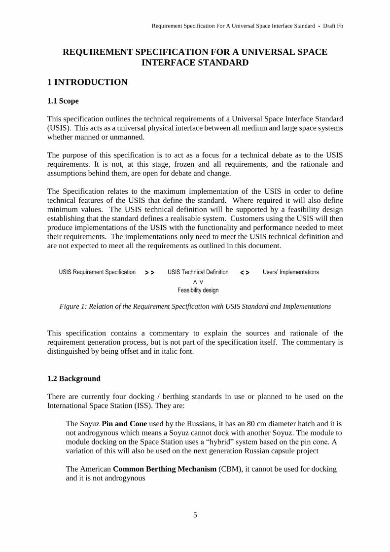
are not expected to meet all the requirements as outlined in this document.
USIS Requirement Specification > > USIS Technical Definition < > Users’ Implementations
˄ ˅
Feasibility design
Figure 1: Relation of the Requirement Specification with USIS Standard and Implementations
This specification contains a commentary to explain the sources and rationale of the
requirement generation process, but is not part of the specification itself. The commentary is
distinguished by being offset and in italic font.
1.2 Background
There are currently four docking / berthing standards in use or planned to be used on the
International Space Station (ISS). They are:
The Soyuz Pin and Cone used by the Russians, it has an 80 cm diameter hatch and it is
not androgynous which means a Soyuz cannot dock with another Soyuz. The module to
module docking on the Space Station uses a “hybrid” system based on the pin cone. A
variation of this will also be used on the next generation Russian capsule project
The American Common Berthing Mechanism (CBM), it cannot be used for docking
and it is not androgynous
Requirement Specification For A Universal Space Interface Standard - Draft Fb
6
The Androgynous Peripheral Attach System (APAS), A system of Russian origin
(but not used by them) it was used by the Shuttle to dock to the ISS, it has an 80 cm
diameter hatch.
The International Docking System Standard (IDSS) (also known as the Nasa
Docking System, the Low Impact Docking System and the Advanced Docking System)
this American design is going to replace the APAS on the American ISS segment. It
has the same outer connection as the APAS but a different and incompatible docking
system. The standard allows hatch diameters to 80 cm after stowing of the capture
guidance vanes. This is system is expected to be used by the US commercial suppliers
of crew delivery to the ISS.
There are two other known docking and berthing systems currently in planning or in use.
The Chinese Docking System (its official name is not known) is used on the Shenzhou
spacecraft and Tiangong 1 space station. It is a variation on the APAS but the actual
degree of compatibility with APAS is not known.
The Boeing Soft Impact Mating Attenuation Concept (SIMAC) which has replaced
the IDSS system on the Orion Spacecraft. Its design is not public but it “post docking
passageway, or tunnel connecting the two joined spacecraft and through which
astronauts and cargo pass; as well as weight and cost considerations” (AW&ST 26 Dec
2012).
None of these standards meet both of the two critical USIS requirements for both androgynous
operation and a large enough hatch size and it also clear that none of them are fully accepted
as a universal international standard although all ISS partners have agreed the IDSS in the
context of the International Space Station and the space exploration initiative although in most
cases the developments even in this area are not using it.
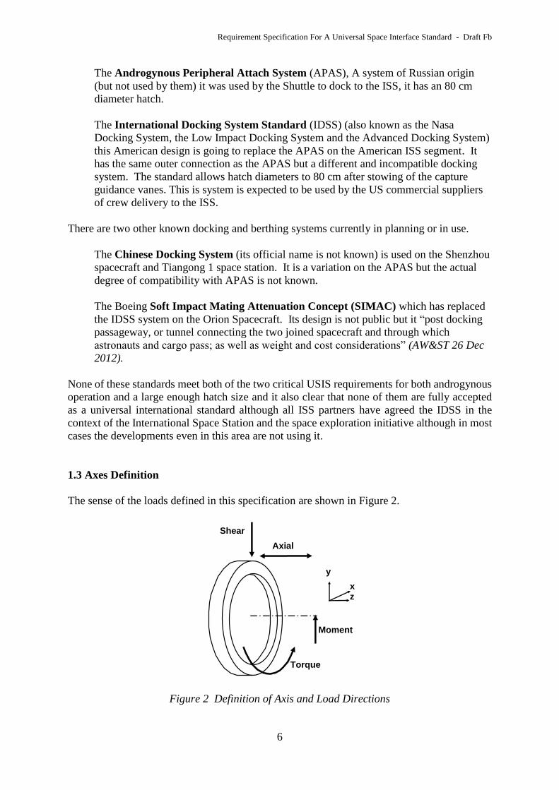
1.3 Axes Definition
The sense of the loads defined in this specification are shown in Figure 2.
Figure 2 Definition of Axis and Load Directions
Shear
Torque
Moment
Axial
zx
y
Requirement Specification For A Universal Space Interface Standard - Draft Fb
7
2 PURPOSE AND OBJECTIVES
The purpose of the Universal Space Interface Standard is
to be a standard connection that maximises the interconnectivity between independent
systems in both the open space (orbital) and celestial body surface environments.
To serve this purpose the USIS shall meet the following objectives:
i. to provide a make and breakable connection between space systems in orbit
ii. to provide an interface for the connection of payloads to transport systems suitable for
both ground to space and in orbit launch systems
iii. to provide a pressurised access path between systems suitable for a universal human
presence in space
The Purpose’s reference to celestial bodies will require some restriction but must include the
Moon, Mars. It is intended to include all bodies without atmosphere’s and a surface gravity
below 1 earth gravity, and exceptions to this in the Solar System will need to be identified
during the USIS definition activity. It includes earth for training and system test purposes. It
can exclude Venus and Titian and all gas giants.
In iii a “universal human presence” means a presence of any human i.e. not restricted to trained
astronauts. This should include for example all age groups, all anthropometric ranges and
disabled people covered by terrestrial access rights.
The connection shall be structural, electric and electronic and include provisions for fluid and
solid object transfer as defined by this specification.

Requirement Specification For A Universal Space Interface Standard - Draft Fb
8
3 FUNCTIONAL REQUIREMENTS
3.1 Type of Connection
3.1.a The USIS shall be able for support four different types of connection as defined in Table
1
Description Contact
Velocity
Contact forces Misalignment
Level I -
Integrated
Ground made
connection either
permanent or
breakable
Negligible Ground handling Millimetres
Level II -
Berthing
In orbit connection
with a manipulator
Nominally zero
Below .01 m/s
Around 100 N centimetres
Level III-
Hard Docking
In orbit connection
between two free
flying spacecraft Tenths of a m/s kNs
Tens of
centimetres
+ a few degrees
Level IV-
Soft Docking
As hard docking with
active control to
reduce impact loads
Table 1: USI Functional Levels
Level I is intended for use a launch vehicle / spacecraft interface or a permanent connection
between modules during ground integration before launch.
Level II is intended for the permanent (or long term) connection of spacecraft modules in orbit –
a current example is the Common Berthing Mechanism on the ISS.
Level III and Level IV are for the temporary connection of space systems. The values are typical
of the definition of these terms form past standards. Hard docking is suitable for small robust
spacecraft (for example Soyuz) and uses simple mechanical shock attenuation during the capture
process. Soft docking is defined as the active control of the capture process to reduce loads and
is required when large or delicate systems are involved. Indeed there is not a hard boundary
between these two levels as capture technology can range from simple springs and shock
absorbers through extendable platforms through to fully control capture. The specification for
two levels is intended to capture this range and thus allow users to employ the technology most
suitable for their requirements.
3.1.b All the USIS levels shall have versions that can be pressurised and version that cannot be
pressurised. This requirement is a consequence of the third objective.
3.1.c All USIS functionality with the exclusion of redundancy shall be possible with only one
side of the interface active (powered). This enables USIS to connect to unpowered system such as satellites during launch, or dead
spacecraft.
Requirement Specification For A Universal Space Interface Standard - Draft Fb
9
3.2 USIS Interconnectivity
3.2.a The USIS shall be fully androgynous. That is any USIS implementation can connect at
its own connection level with any other USIS regardless of the second USIS’s connection level.
For clarification it means different levels can be connected together at functionality of the lower
of levels of the two interfaces. Thus a spacecraft with a Level 4 USIS could be integrated by that
interface on to a launch system with a Level 1 USIS. The ability of space systems to be able to
connect to any other, even copies of itself demands an androgynous technical solution and this
is an already widely accepted principle e.g.it is part of the IDSS philosophy.
3.3 Load Bearing Connections
3.3.0 Nothing in this section requires the permanent, one use and mated connections to be
separate systems nor that they have to be combined into a single system.
3.3.1 Permanent Connection
3.3.1.a All levels of USIS shall have provision for a permanent (or semi-permanent) connection
(called a permanent connection) which does not require an active mechanism to be made (e.g.
a bolted connection).
This requirement allows for a cheaper USIS option when the need is for a permanent connection
which does not need to made and unmade during its operational life in space. It corresponds to
a Level I capability. An example would be the ground integration of two modules before launch.
3.3.1.b The Permanent Connection shall be able to made manually both during terrestrial
ground integration facilities and by astronauts in orbit. The connection shall be on the exterior
of the USIS.
The exterior connection requirement stems from the most likely in orbit application where two
systems are held together by manipulators while the connection is made. In this case only the
exterior of the USIS would be accessible. It is also most likely to be the most convenient for
ground integration.
3.3.1.c The Permanent Connection shall be able to carry the following loads
Axial Compressive 1,180 kN
Axial Tension 600 kN
Shear 200 kN
Moment 1,000 kN m
Torque 80 kN m
Each axial load in turn and both the shear/moment loads and torque loads shall be assumed to
be applied simultaneously (i.e. compressive+shear+moment+torque or tension+shear
+moment +torque).
The compressive tension and moment loads are double the values for the mated
connection which would be the case if two connected USISs both activate their mated
connections.
Requirement Specification For A Universal Space Interface Standard - Draft Fb
10
3.3.2 One Use Connection
3.3.2.a The USIS at Levels II, III and IV shall have a capture mechanism capable of being
integrated Level I with the requirements defined in section 3.3.1 but breaking in operation
called the One Use Connection.
This requirement is needed to enable both docking and berthing operations. Used alone it
provides the Level 2 capability. Used in conjunction with a capture system (defined in 3.4) it
provides a docking capability Level III and level IV.
3.3.2.b During separation operations the maximum shock force generated by the One Use
Connection shall be ?? N in any direction.
A place holder requirement.
3.3.3 Mating Connection
3.3.3.a The USIS at Levels II, III and IV shall have a capture mechanism capable of making
and breaking a load carrying connection (called a Mating Connection).
This requirement is needed to enable both docking and berthing operations. Used alone it
provides the Level 2 capability. Used in conjunction with a capture system (defined in 3.4) it
provides a docking capability Level III and level IV.
3.3.3.b The USIS Mating Connection mechanism shall be able to accommodate lateral
misalignments of 30 mm.
The lateral numerical value is similar to the misalignment capability of the ISS Common Berthing
Mechanism and corresponds to the placement accuracy of the ISS Manipulator.
3.3.3.c During the mating operation the maximum force generated by the Mating Connection
System external to the USIS (excluding shock) shall be 150 N in any direction. After mating
the static forces created by the mating connection shall be contained within the USIS.
The 150 N requirement is to be consistent with the Forces that can be generated by the ISS
manipulator.
3.3.3.d During the mating operation the maximum shock force generated by the Mating
Connection System external to the USIS shall be ??? N in any direction.
A place holder requirement.

Requirement Specification For A Universal Space Interface Standard - Draft Fb
11
3.3.3.e The maximum axial force required to make the USIS Mated Connection shall be below
150 N.
The 150 N requirement is to be consistent with the Forces that can be generated by the ISS
manipulator.
3.3.4 Load Carrying Requirements
3.3.4.a For Unpressurised operation the One Use Connection and the Mating connections shall
be able to support the following loads.
Axial Compressive 590 kN
Axial Tension 300 kN
Shear 200 kN
Moment 500 kN m
Torque 80 kN m
Each axial load in turn and both the shear/moment loads and torque loads shall be assumed to
be applied simultaneously (i.e. compressive+shear+moment+torque or tension+shear
+moment +torque).
These requirements were derived from consideration of a 10 tonne payload with a Centre
of Mass 2.5 m above the interface ring on Falcon 9, Ariane 5 and Reaction Engines’
Skylon launch systems with acceleration values taken from their respective User
Manuals, the worst case forming the specification value, as shown in the table below.
Case Ariane 5 Falcon 9 Skylon
Compressive 4.55 + 1 = 5.55 g 6g 0.5g
Tension 0g 2g 3g
Lateral (shear) 0.25+0.8 = 1.05g 2g 2g Skylon values assumes payload is mounted rear facing
Other case looked at were 2 Vinci engines assumed on an in orbit stage (as used on the
Reactions engines Flyut Stage) would give a compressive load of 350 kN. Also a 100
tonne payload accelerated at an orbit manoeuvring acceleration of 1/3 g would give a
compressive load 300 kN. All these other cases were scoped by the cases shown in the
table.
The torque requirements comes from a Skylon firing two of its forward thrusters 2 x 1 kN
taken as 40 metres from connection axis gives 80 kN m.
3.3.4.b The pressurised Mating Connection shall be able to support the following loads while
the mating is pressurised to a design pressure load of 200 kPa.
Axial Compressive 100 kN
Axial Tension 100 kN
Shear 120 kN
Moment 300 kN m
Torque 80 kN m
All the defined loads shall be assumed to be applied simultaneously with the pressure load.
Requirement Specification For A Universal Space Interface Standard - Draft Fb
12
This assumes that the connection will not be pressurised during launch or other high
acceleration situations.
The pressure load is above the value assumed by the IDSS. It would allow the USIS to
be used in a system at hyperbaric pressures. Another logic for the higher value is to
ensure that the design is acceptable when the USIS is certified for public access use at 1
bar.
Compression and tension loads are derived from a 100 tonne system such as the Space
Shuttle, a connection in the middle of a large human spaceflight system which is
accelerated at 1/10 g. If the Centre of Mass is assumed tonne 3 m off axis then the
moment 300 kN m.
Shear load is generated from a 30 tonne module cantilevered off a Martian human
facility.
The Torque requirement is a nominal value repeating the logic used for the pressurised
connection requirements. Defined below in section 3.3.3.c
3.3.4.c The Mating Connection mechanism shall have redundancy and be able to operate and
carry the above unpressurised loads (that is those defined in 3.3.3.b) with one mechanism
failures.
The requirement for failure tolerance applied to the unpressurised connection on the
assumption this will not always we safety critical so one failure tolerance will be
acceptable. Further when used as a launch system interface (when the full loads are
most likely to be seen) the operation of all latches and hence their load carrying
capability can be confirmed before launch.
The permanent connection is assumed to be structural an exempt from this reliability
related safety requirements (i.e. safety requirements would be covered in the
connection’s stress analysis).
3.3.4.d The Mating Connection mechanism shall have redundancy and be able to operate and
carry the above pressurised loads (that is those defined in 3.3.3.c) with two mechanism failures.
It has been assumed that when mated and pressurised the connection becomes a safety
critical item requiring two failures before a hazardous condition is created.
3.3.4.e When two USIS are connected both USIS shall be able to activate their mated
connections at the same time.
This requirement is both a safety requirement in that inadvertent operation of a USIS
mated connection when the other is already active should not introduce forces that break
the USIS. It also added to the load carrying capability when two active USIS are
connected without any significant mass impact.
3.4 Capture System

Requirement Specification For A Universal Space Interface Standard - Draft Fb
13
3.4.1 Capture System
3.4.1.a The USIS implementations at Level III and IV shall have a provision for a soft capture
system that enables two systems to physically connect and orientate such that the mating
connection defined in Section 3.3.2 can function.
This requirement is simply stating a consequence of the need to dock large systems (Shuttle size)
and delicate system (such as communications satellites).
3.4.2 Capture Misalignment
3.4.2.a The capture system shall be able to connect systems that at the point of first contact
have a misalignment in any direction in the x y plane (Figure 1) of 110 mm together with a
rotational misalignment about any axis in the x y plane of 5 degrees round the Z axis of 5
degrees.
These requirements are identical to the stated performance of the IDSS.
3.4.3 Relative Motion
3.4.3.a In the case of one of the docking systems having infinite mass and inertias and the other
system has a mass of 100 tonnes, with a Centre of Mass offset from the axis of 2 m and with
an inertia about each axis of 2,000,000 kg m2. The soft capture mechanism shall be able to
operate when the relative speed of the two docking systems is 0.1 m/s along Z axis, 0.04 m/s
around any axis in the x y plane and rotational speeds of 0.4 degrees/s. about Z axis and 0.15
degrees/s about vector sum of X and Y axes.
This requirement is based on an assumption of a large 100 tonne system with dimensions
of 10s of metres. It corresponds to a system like the Shuttle or Skylon - but a little larger.
The closing conditions are taken from the IDSS requirements
3.4.4 Maximum Applied Forces
3.4.4.a During operation (from impact to capture) the soft capture system shall operate not
generate loads greater 10 kN in compression and than 4 kN in all other directions. Maximum
moments shall be less than 3 kN m.
This value is derived from, but not copied, from the IDSS values; they are slightly higher.
3.5 Alignment Requirements
3.5.1 Alignment System
The USIS shall have a provision for guidance sensors that can measure linear range and angular
misalignment between two USIS implementations at Level III or Level IV (i.e. equipped for
docking). The system shall work with active sensor elements on only one (active) USIS. The
passive side shall have only passive targets.
Requirement Specification For A Universal Space Interface Standard - Draft Fb
14
The active/passive requirement is to enable the USIS to dock with passive (unpowered) variants
in accordance with requirement 3.1.c.
3.5.2 Alignment System Range
3.5.2.a The USIS alignment shall operate with a maximum separation between USIS
implementations of 20 metres.
It is assumed that GPS or other navigation systems would enable the two spacecraft to know their
relative positions to within 2 meters. Therefore 20 meters means a factor of 10 overlap between
other navigations and the terminal guidance.
3.5.3 Alignment System Accuracy
3.5.3.a The range (z axies separation) shall be measured with an accuracy of 0.01 m or smaller.
The rate of range (relative velocity) shall be measured to an accuracy of lower than 0.01 m/sec.
The range accuracy has no functional derivation and is determined by available technology. The
velocity requirement is 5% of the assumed maximum closing speed in a hard dock operation.
3.5.3.b The linear misalignment in the x/y plane shall be measured to better than 0.01 m or
smaller.
3.5.3.c The rotational misalignments shall be measured to 0.25 degrees or smaller.
The linear, roll, pitch and yaw misalignment accuracies are 5% of the alignment accuracy
required for the docking capture mechanism.
3.6 Separation System
3.6.a The USIS shall be able to break the mating system in a controlled manner.
A functional requirement derived from the first objective.
3.6.b The USIS separation system shall provide a maximum separation force of 10 kN.
The 10 kN means a means 1 g acceleration for a 1 tonne payload and 0.1 g acceleration
for a 10 tonne payload. The force is three times the 3.4 kN specified by the IDSS.
There may be a case for an intelligent separation system which can vary the force but fix
the travel and speed of the mechanism.
3.7 Utility Connection Requirements
3.7.1 Power Connection
Requirement Specification For A Universal Space Interface Standard - Draft Fb
15
3.7.1.a The USIS shall have the provision to supply electrical power in either direction from
one connected system to the other. The provision shall be capable of transferring a maximum
current of 17 Amperes at 28Volts.
28 Volts is an aeronautical DC supply standard also widely used in space. 17 Amperes
current corresponds to around 0.5 Kilowatts and matches the capability of the APAS.
3.7.2 Data Connection
3.7.2.a Once connected the docking port shall have provision for a full duplex data link with a
capacity of at least 20 Mbps in each direction with an error rate below 1 in 1013.
3.7.2.b The data link shall have a handshake protocol upon connection that shall work
independent of the power system status on one of the connected systems (i.e. one of the systems
can be electrically dead).
3.7.2.c The handshake shall include as a minimum:
- System identification
- Hazard warnings (propellant type, high pressure systems, hazardous materials, explosive
systems)
- Emergency Alarm status i.e. is the system in an emergency condition and the type of
emergency
- System status as held by the flight recorder (e.g. Power status, cabin pressure and
contamination, system mass properties)
The intention is to establish a temporary system to system data link (i.e. while connected) that
does not use RF bandwidth. Its purpose is to enable the exchange of system status and other
telemetry information, real time crew communication (audio and video), computer files (e.g.
emails, documents etc) and commands (where appropriate). The minimum speed of 20 Mbps was
established for the following reasons:
- It has been judge suitable for temporary Spacewire links
- It exceeds the capability of non-High Speed USB (i.e. v1.0 and v1.1) of 12 Mbps
- It is a typical speed offered to home broadband and therefore it is consistent with
audio and low definition video.
The handshake is primarily intended for emergency docking situations, including with dead
systems, to provide the rescue spacecraft with minimum information to plan further activity after
the connection has been made.
3.7.3 USIS Control Connection
3.7.3.a The USIS shall have a connection that provides power and command capability to
control another unpowered active USIS to which it is attached to it.
Requirement Specification For A Universal Space Interface Standard - Draft Fb
16
This is a safety requirement to enable a system to separate from another dead space
system that has its mating connection closed.
3.7.4 Fluid Connections
Fluid Connections are to be determined.
3.8 Through Access Requirements
3.8.1 Passive Protrusion Allowance
3.8.1.a The USIS shall be compatible with a rocket engine nozzle through the USIS Z axis as
defined by Figure 1 with a diameter of at least 900 mm and a protrusion beyond the x y plane
of the passive side of the USIS system of at least 150 mm.
Satellite apogee engines have a smaller diameter the largest is probably the 1.1 kN Ampac High
thrust apogee engines under development with ESA with an exit diameter of around 500mm
Satellite apogee engines tend to exploit the space below the separation plane. The protrusion
allowance on the Ariane 5 interfaces are:
Interface Minimum diameter Depth
917 440 mm 683 mm
1194 754 mm 590 mm
1663 1054 mm 686 mm
However the depth values are judged too large for practical implementations of the USIS and 150
mm was selected as a value realistic for USIS based on early concept design but achieving the
objective to project the rocket engine exit beyond the vehicle.
3.8.2 Pressurised Main Passageway
3.8.2.a The USIS shall provide free access to a pressurised transfer passageway that shall have
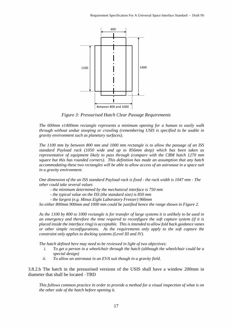
an opening that accommodates the two rectangles defined in Figure 3. The 800mm to 1000mm
dimension express a desirable range with 800mm being the minimum acceptable and up to
1000 mm being better. Some reconfiguration of the capture system is acceptable to
accommodate the 1100 by 800 to 1000 rectangle.
Requirement Specification For A Universal Space Interface Standard - Draft Fb
17
Figure 3: Pressurised Hatch Clear Passage Requirements
The 600mm x1400mm rectangle represents a minimum opening for a human to easily walk
through without undue stooping or crawling (remembering USIS is specified to be usable in
gravity environment such as planetary surfaces).
The 1100 mm by between 800 mm and 1000 mm rectangle is to allow the passage of an ISS
standard Payload rack (1050 wide and up to 856mm deep) which has been taken as
representative of equipment likely to pass through (compare with the CBM hatch 1270 mm
square but this has rounded corners). This definition has made an assumption that any hatch
accommodating these two rectangles will be able to allow access of an astronaut in a space suit
in a gravity environment.
One dimension of the an ISS standard Payload rack is fixed - the rack width is 1047 mm - The
other could take several values
- the minimum determined by the mechanical interface is 750 mm
- the typical value on the ISS (the standard size) is 850 mm
- the largest (e.g. Minus Eight Laboratory Freezer) 966mm
So either 800mm 900mm and 1000 mm could be justified hence the range shown in Figure 2.
As the 1100 by 800 to 1000 rectangle is for transfer of large systems it is unlikely to be used in
an emergency and therefore the time required to reconfigure the soft capture system (if it is
placed inside the interface ring) is acceptable. This is intended to allow fold back guidance vanes
or other simple reconfigurations. As the requirements only apply to the soft capture the
constraint only applies to docking systems (Level III and IV).
The hatch defined here may need to be reviewed in light of two objectives:
i. To get a person in a wheelchair through the hatch (although the wheelchair could be a
special design)
ii. To allow an astronaut in an EVA suit though in a gravity field.
3.8.2.b The hatch in the pressurised versions of the USIS shall have a window 200mm in
diameter that shall be located –TBD
This follows common practice in order to provide a method for a visual inspection of what is on
the other side of the hatch before opening it.
600
14001100
Between 800 and 1000
Requirement Specification For A Universal Space Interface Standard - Draft Fb
18
3.8.3 Secondary Hatch Opening
3.8.3.a The pressurised versions of USIS shall have a secondary sealable opening (or openings
up to a maximum of 4) in additional to the main hatch and suitable for permanent system to
system utility connection.
3.8.3.b. The secondary hatch provision shall provide a cross section of a minimum of 0.05 m2.
The purpose of this secondary utility opening provision is so air flow ducting and other utility
connections such as power, data, or fluids can be made between modules of stations and bases
which do not involve the main hatch being permanently open or interfere with the clear passage
requirements defined in paragraph 3.6.3a. The value is based on the Russian intermodule
through hatch air ducting scales at around 0.25 m diameter giving an area of .049m2. (a
reference for the size of this has not been found). Another comparison point is the SpaceX Dragon
has a 5 inch diameter inter module air vent (area .0126 m2) (Brenda J. Hernandez1, Siarhei
Piatrovich, and Mauro Prina, “SpaceX Dragon Air Circulation System”). Any wiring and fluid
connections (e.g. water) were assumed to be negligible compared with the likely air circulation
requirements in defining this requirement.
Requirement Specification For A Universal Space Interface Standard - Draft Fb
19
4 DESIGN REQUIREMENTS
4.1 Load Safety Factors
4.1.a Safety factors on design loads shall be at least 1.5 on ultimate failure and 1.25 on yield.
The factors are a little higher than have been normal for space systems to reflect that it
is an interface and account should be made that the other side of the interface is not in
the control of the system. It is also expected that some USIS will have long service life
and higher safety factor more appropriate.