rescue tools daily care & preventive maintenance · rescue tools daily care & preventive...
TRANSCRIPT

Rescue Tools Daily Care & Preventive
Maintenance
How to keep your LUKAS Tools in perfect condition

PT Hydraulics Australia Pty Ltd Page 2 Sep 2014
Contents Contents ..................................................................................................................................................... 2 Introduction ................................................................................................................................................ 3 Maintenance for Hydraulic Pumps ............................................................................................................. 4
Introduction ............................................................................................................................................ 4 Visual & User check after each use ........................................................................................................ 6 Pump unit ............................................................................................................................................... 6 Petrol Engine .......................................................................................................................................... 6 Electric Motor ......................................................................................................................................... 6 Handpump .............................................................................................................................................. 6 Hydraulic hoses ...................................................................................................................................... 6 Function and Load Test .......................................................................................................................... 7
Maintenance for spreaders ........................................................................................................................ 8 Introduction ............................................................................................................................................ 8 Visual & User check after each use ........................................................................................................ 9 Spreader arms and tips ........................................................................................................................... 9 Spreader Body ........................................................................................................................................ 9 Hydraulic hoses ...................................................................................................................................... 9 Function and Load Test .......................................................................................................................... 9
Maintenance for cutters ........................................................................................................................... 10 Introduction .......................................................................................................................................... 10 Visual & User check after each use ...................................................................................................... 11 Cutter blades ........................................................................................................................................ 11 Cutter Body ........................................................................................................................................... 11 Tensioning the Centre Bolt ................................................................................................................... 11 Method for Checking Centre Bolt Tension ........................................................................................... 12 Hydraulic hoses .................................................................................................................................... 12 Function and Load Test ........................................................................................................................ 12
Maintenance for combination tools ......................................................................................................... 13 Introduction .......................................................................................................................................... 13
Table 1: Tightening torques for central bolts on cutters and combination tools ..................................... 14 Maintenance for rescue rams................................................................................................................... 15
Introduction .......................................................................................................................................... 15 Visual & User check after each use ...................................................................................................... 16 Claws on cylinder bottom and piston ................................................................................................... 16 Rescue ram body .................................................................................................................................. 16 Hydraulic hoses .................................................................................................................................... 16 Function and Load Test ........................................................................................................................ 16
Maintenance for Hoses & Hose Reels ...................................................................................................... 17 Introduction .......................................................................................................................................... 17 Visual & User check after each use ...................................................................................................... 17 Examples of possible defects of hose ................................................................................................... 17 Safety Instruction ................................................................................................................................. 18 Taking Care of Hoses ............................................................................................................................ 19
Streamline couplings…………………………………………………………………………………………………………………………….18 Adjustable Ram support……………………………………………………………………………………………………………………….18 Frequently Asked Questions ..................................................................................................................... 21
PT Hydraulics Australia Pty Ltd Page 3 Sep 2014
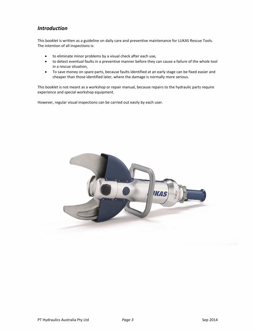
Introduction This booklet is written as a guideline on daily care and preventive maintenance for LUKAS Rescue Tools. The intention of all inspections is:
to eliminate minor problems by a visual check after each use,
to detect eventual faults in a preventive manner before they can cause a failure of the whole tool in a rescue situation,
To save money on spare parts, because faults identified at an early stage can be fixed easier and cheaper than those identified later, where the damage is normally more serious.
This booklet is not meant as a workshop or repair manual, because repairs to the hydraulic parts require experience and special workshop equipment. However, regular visual inspections can be carried out easily by each user.

PT Hydraulics Australia Pty Ltd Page 4 Sep 2014
Maintenance for Hydraulic Pumps
Introduction The daily care and maintenance of pumps is the same irrespective of the model. A selection of the current range of pumps available is pictured below:
Model
P620OG Compact
• Super compact pump – only 15 kg • High mobility through compact design • Designed for long run times • Operated by high-quality HONDA engine • Low noise level
GS-2 L & P620SG Compact Simo
• Weight only 24.8 kg for simultaneous operation of all LUKAS Rescue Tools
• High mobility through compact design • Designed for long run times • Operated by high-quality HONDA engine • Low noise level
P620SD Diesel Simo
• 4 stroke diesel engine • Weight 54 kg • simultaneous operation of all LUKAS
Rescue Tools
P620SE Electric Simo
• Electric motor • Weight 32 kg • simultaneous operation of all LUKAS
Rescue Tools
P630SG Compact Simo
• Weight only 23.9 kg for simultaneous operation of all LUKAS Rescue Tools
• High mobility through compact design • Designed for long run times • Operated by high-quality HONDA engine • Low noise level • Turbo function (double oil flow)
PT Hydraulics Australia Pty Ltd Page 5 Sep 2014
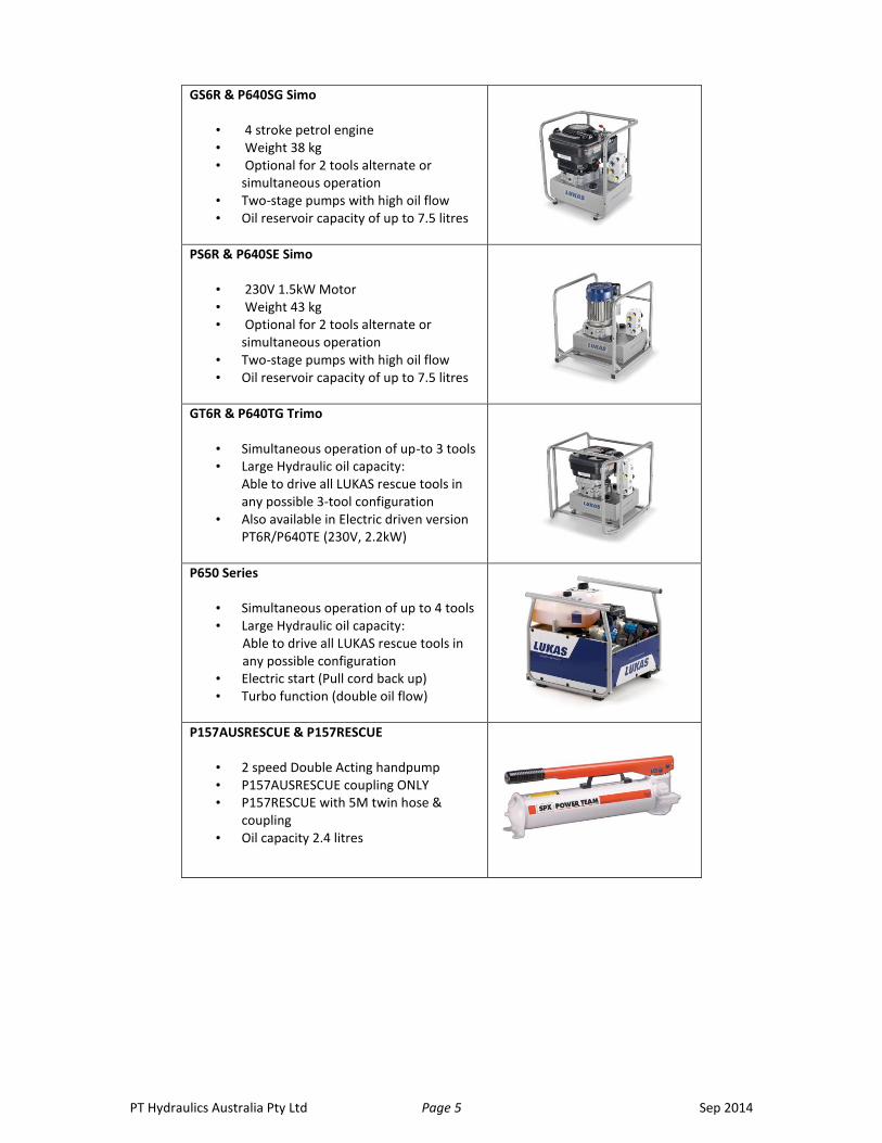
GS6R & P640SG Simo
• 4 stroke petrol engine • Weight 38 kg • Optional for 2 tools alternate or
simultaneous operation • Two-stage pumps with high oil flow • Oil reservoir capacity of up to 7.5 litres
PS6R & P640SE Simo
• 230V 1.5kW Motor • Weight 43 kg • Optional for 2 tools alternate or
simultaneous operation • Two-stage pumps with high oil flow • Oil reservoir capacity of up to 7.5 litres
GT6R & P640TG Trimo
• Simultaneous operation of up-to 3 tools • Large Hydraulic oil capacity:
Able to drive all LUKAS rescue tools in any possible 3-tool configuration
• Also available in Electric driven version PT6R/P640TE (230V, 2.2kW)
P650 Series
• Simultaneous operation of up to 4 tools • Large Hydraulic oil capacity:
Able to drive all LUKAS rescue tools in any possible configuration
• Electric start (Pull cord back up) • Turbo function (double oil flow)
P157AUSRESCUE & P157RESCUE
• 2 speed Double Acting handpump • P157AUSRESCUE coupling ONLY • P157RESCUE with 5M twin hose &
coupling • Oil capacity 2.4 litres

PT Hydraulics Australia Pty Ltd Page 6 Sep 2014
Visual & User check after each use A visual & user check should be carried out after each use of the pump. The pump, engine and the hydraulic hoses should be checked for the following:
Pump unit
correct hydraulic oil level
oil leakage on the seal of oil container and valve block
condition of carrying frame
Petrol Engine
any visible external damage
condition of the rope starter
electric start battery charged (P650 series)
correct motor oil level
any Oil or Petrol leaks
Diesel Engine
any visible external damage
condition of the rope starter
correct motor oil level
any Oil or Diesel leaks
Electric Motor
any visible external damage
condition of electric cable and plug, including cable entry into the motor and cable strain relief
proper function of the on/off-switch
Handpump
correct hydraulic oil level
oil leakage from filler plug and valve block
any visible external damage
pump handle firmly fixed to piston assembly
Hydraulic hoses
condition of the end fittings
leakage on the connection to the valve block
visible surface defects such as cracks, kinks, abrasions or bubbles
condition and smooth operation of quick couplers
presence and condition of dust caps
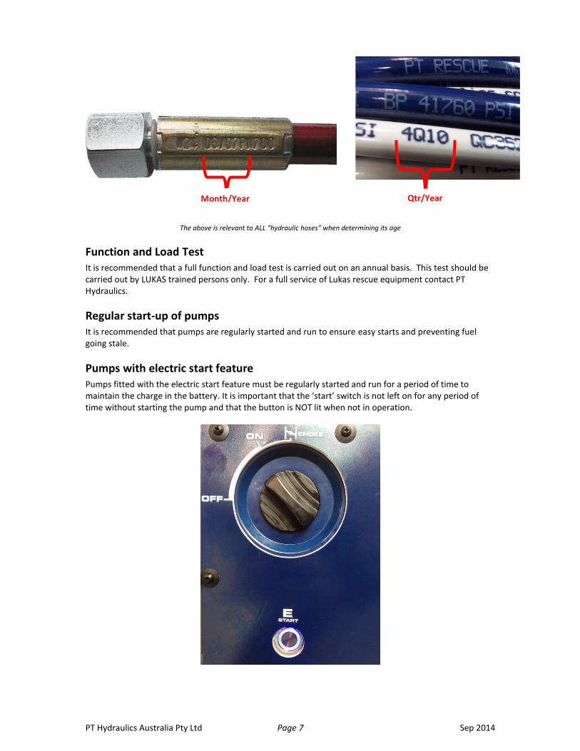
Hoses not older than 10 years? The date of manufacture (quarter / year) is printed on the hose surface.
PT Hydraulics Australia Pty Ltd Page 7 Sep 2014
The above is relevant to ALL “hydraulic hoses” when determining its age
Function and Load Test It is recommended that a full function and load test is carried out on an annual basis. This test should be carried out by LUKAS trained persons only. For a full service of Lukas rescue equipment contact PT Hydraulics.
Regular start-up of pumps It is recommended that pumps are regularly started and run to ensure easy starts and preventing fuel going stale.
Pumps with electric start feature Pumps fitted with the electric start feature must be regularly started and run for a period of time to maintain the charge in the battery. It is important that the ‘start’ switch is not left on for any period of time without starting the pump and that the button is NOT lit when not in operation.
Month/Year Qtr/Year

PT Hydraulics Australia Pty Ltd Page 8 Sep 2014
Maintenance for spreaders
Introduction The daily care and maintenance of spreaders is the same irrespective of the model. A selection of the current range of spreaders available is pictured below:
Model
SP300
• 17 kg operating weight • 605 mm spreading distance • Spreading force 34 – 112 kN
LSP40EN & SP310
• 19.6 kg operational weight • 720 mm spreading distance • Spreading force up to 256 kN
LSP60EN & SP510
• 24.9 kg operational weight • 800 mm spreading distance • Spreading force up to 230 kN
LSP80EN & SP512
• operational weight 25.9 kg • Spreading distance 610 mm • Spreading force at tips (closed arm
position) 128 kN • Spreading force up to 540 kN
PT Hydraulics Australia Pty Ltd Page 9 Sep 2014
Visual & User check after each use A visual & user check should be carried out after each use of the spreader. The spreader Arms, body and hoses should be checked for the following
Spreader arms and tips
visible external damage
condition of bearing bolts and securing rings
serration of spreader tips clean and sharp
fixing mechanism of spreader tips in sound condition
Spreader Body
oil leakage on cylinder body or control valve
protection cover for lever arms in good condition
carry and pipe handles in good condition and properly tightened
control valve returns to centre position smoothly when released (dead man function)
Hydraulic hoses
condition of the end fittings
leakage on the connection to the valve block
visible surface defects such as cracks, kinks, abrasions or bubbles
condition and smooth operation of quick couplers
presence and condition of dust caps
Hoses not older than 10 years? The date of manufacture (quarter / year) is printed on the hose surface.
Protection Cover
the area behind the protection cover should be checked and cleared of any debris, liquids and solutions.
Stowage
the tool should be stowed with the spreader tips slightly open (not under pressure)
Function and Load Test It is recommended that a full function and load test is carried out on an annual basis. This test should be carried out by LUKAS trained persons only. For a full service of Lukas rescue equipment contact PT Hydraulics.
PT Hydraulics Australia Pty Ltd Page 10 Sep 2014
Maintenance for cutters
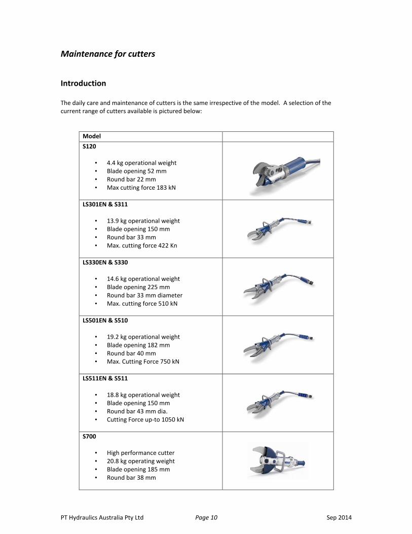
Introduction The daily care and maintenance of cutters is the same irrespective of the model. A selection of the current range of cutters available is pictured below:
Model
S120
• 4.4 kg operational weight • Blade opening 52 mm • Round bar 22 mm • Max cutting force 183 kN
LS301EN & S311
• 13.9 kg operational weight • Blade opening 150 mm • Round bar 33 mm • Max. cutting force 422 Kn
LS330EN & S330
• 14.6 kg operational weight • Blade opening 225 mm • Round bar 33 mm diameter • Max. cutting force 510 kN
LS501EN & S510
• 19.2 kg operational weight • Blade opening 182 mm • Round bar 40 mm • Max. Cutting Force 750 kN
LS511EN & S511
• 18.8 kg operational weight • Blade opening 150 mm • Round bar 43 mm dia. • Cutting Force up-to 1050 kN
S700
• High performance cutter • 20.8 kg operating weight • Blade opening 185 mm • Round bar 38 mm
PT Hydraulics Australia Pty Ltd Page 11 Sep 2014
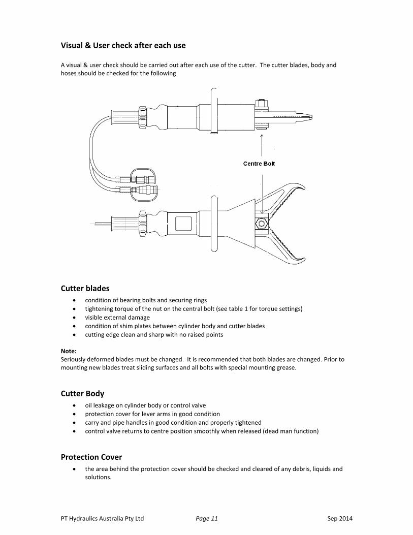
Visual & User check after each use A visual & user check should be carried out after each use of the cutter. The cutter blades, body and hoses should be checked for the following
Cutter blades
condition of bearing bolts and securing rings
tightening torque of the nut on the central bolt (see table 1 for torque settings)
visible external damage
condition of shim plates between cylinder body and cutter blades
cutting edge clean and sharp with no raised points
Note: Seriously deformed blades must be changed. It is recommended that both blades are changed. Prior to mounting new blades treat sliding surfaces and all bolts with special mounting grease.
Cutter Body
oil leakage on cylinder body or control valve
protection cover for lever arms in good condition
carry and pipe handles in good condition and properly tightened
control valve returns to centre position smoothly when released (dead man function)
Protection Cover
the area behind the protection cover should be checked and cleared of any debris, liquids and solutions.
PT Hydraulics Australia Pty Ltd Page 12 Sep 2014
Stowage
the tool should be stowed with the cutter tips slightly overlapping
Tensioning the Centre Bolt The centre bolt should be tensioned on a regular basis to ensure the correct operation of the cutter. The actual frequency of checking the tension is dependent on use. For normal road crash rescue operations and training the torque setting should be checked every 3 months. Where the tool has been subject to heavy operational use they should be checked on completion of the work
Method for Checking Centre Bolt Tension
Visually inspect nut and bolt for damage.
Loosen nut by 1/4 of turn. NOTE: S700 cutter requires grub screw in nut to be loosened before adjusting nut tension. Remember to re-tighten grub screw.
Adjust torque wrench to correct setting and tighten nut.
Torque settings for all tools are listed in the table 1.
Hydraulic hoses
condition of the end fittings
leakage on the connection to the valve block
visible surface defects such as cracks, kinks, abrasions or bubbles
condition and smooth operation of quick couplers
presence and condition of dust caps
Hoses not older than 10 years? The date of manufacture (quarter / year) is printed on the hose surface.
Function and Load Test It is recommended that a full function and load test is carried out on an annual basis. This test should be carried out by LUKAS trained persons only. For a full service of Lukas rescue equipment contact PT Hydraulics.

PT Hydraulics Australia Pty Ltd Page 13 Sep 2014
Maintenance for combination tools
Introduction The daily care and maintenance of Combi-tools is the same irrespective of the model. A selection of the current range of Combi-tools available is pictured below:
Model
LKS21EN & SC150
• Cutting Force up to 192 kN • Round Steel up to 22 mm • Spreading Force up to 113 kN • Spreading Distance 265 mm • Weight 10.3 kg
LKS35EN & SC350
• Cutting Force up to 380 kN • Round steel up to 30 mm • Spreading force up to 113 kN • Spreading distance 360 mm • Weight 13.9 kg
SC357
• Cutting force up to 387 kN • Round steel up to 32 mm • Spreading • Spreading distance 365 mm • Weight 14.8 kg
LKS55EN, SC550 & SC557
• Cutting Force up to 535 kN • Round steel up to 37mm • Spreading force 225 kN • Spreading distance 430 mm • Weight 20 kg
The combination tool is a combination of a spreader and a cutter. Carry out the visual and user checks as described above for the spreader and cutter. The torque settings for the combination tool centre bolt can be found in table 1.
Stowage
the tool should be stowed with the tips slightly open (not under pressure)
PT Hydraulics Australia Pty Ltd Page 14 Sep 2014
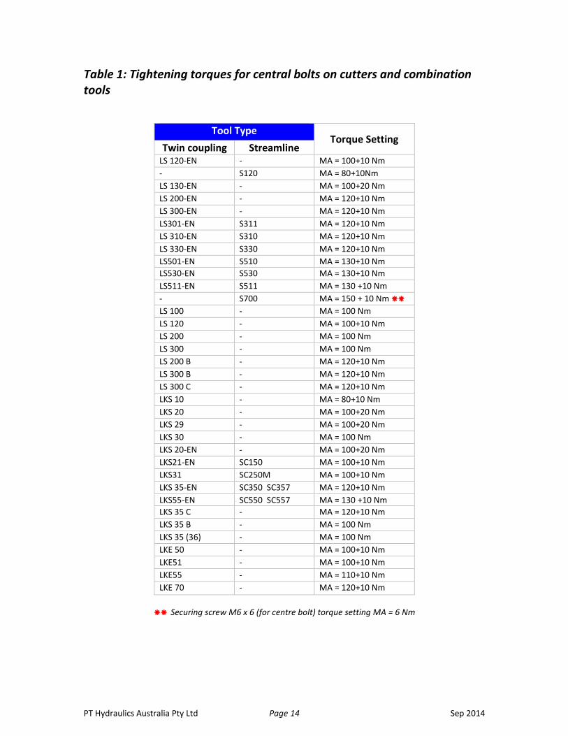
Table 1: Tightening torques for central bolts on cutters and combination tools
Tool Type Torque Setting
Twin coupling Streamline LS 120-EN - MA = 100+10 Nm
- S120 MA = 80+10Nm
LS 130-EN - MA = 100+20 Nm
LS 200-EN - MA = 120+10 Nm
LS 300-EN - MA = 120+10 Nm
LS301-EN S311 MA = 120+10 Nm
LS 310-EN S310 MA = 120+10 Nm
LS 330-EN S330 MA = 120+10 Nm
LS501-EN S510 MA = 130+10 Nm
LS530-EN S530 MA = 130+10 Nm
LS511-EN S511 MA = 130 +10 Nm
- S700 MA = 150 + 10 Nm
LS 100 - MA = 100 Nm
LS 120 - MA = 100+10 Nm
LS 200 - MA = 100 Nm
LS 300 - MA = 100 Nm
LS 200 B - MA = 120+10 Nm
LS 300 B - MA = 120+10 Nm
LS 300 C - MA = 120+10 Nm
LKS 10 - MA = 80+10 Nm
LKS 20 - MA = 100+20 Nm
LKS 29 - MA = 100+20 Nm
LKS 30 - MA = 100 Nm
LKS 20-EN - MA = 100+20 Nm
LKS21-EN SC150 MA = 100+10 Nm
LKS31 SC250M MA = 100+10 Nm
LKS 35-EN SC350 SC357 MA = 120+10 Nm
LKS55-EN SC550 SC557 MA = 130 +10 Nm
LKS 35 C - MA = 120+10 Nm
LKS 35 B - MA = 100 Nm
LKS 35 (36) - MA = 100 Nm
LKE 50 - MA = 100+10 Nm
LKE51 - MA = 100+10 Nm
LKE55 - MA = 110+10 Nm
LKE 70 - MA = 120+10 Nm
Securing screw M6 x 6 (for centre bolt) torque setting MA = 6 Nm

PT Hydraulics Australia Pty Ltd Page 15 Sep 2014
Maintenance for rescue rams
Introduction The daily care and maintenance of Rams is the same irrespective of the model. A selection of the current range of Rams available is pictured below:
Model
LZR 12 Series & R410, R412, R414 Single stage
• Lifting Force up to137 kN • LZR 12/300EN – 300mm Stroke • LZR 12/500EN – 500mm Stroke • LZR 12/700EN – 700mm Stroke • R410 – 300mm Stroke (13T) • R412 – 500mm Stroke (13T) • R414 – 700mm Stroke (13T)
LTR3,5/820 & R430 3-stage telescopic ram
• Extended length: 1305 mm • Retracted length: 480 mm • Unique 3-stage telescopic ram • Pushing force up to 267 kN • Weight 17.5 kg
LTR12/575EN & R420, R422, R424 2-stage telescopic ram
• Extended length: 1505 mm • Retracted length: 480 mm • Pushing force up to 267 kN • 24 tons lifting capacity • Weight up to 20.9 kg
PT Hydraulics Australia Pty Ltd Page 16 Sep 2014
Visual & User check after each use A visual & user check should be carried out after each use of the ram. The ram claws, body and hoses should be checked for the following
Claws on cylinder bottom and piston
Visible external damage
Gripping edges clean and sharp?
Piston clean with no score mark or dents
Rescue ram body
oil leakage on cylinder body or control valve
protection cover for lever arms in good condition
control valve returns to centre position smoothly when released (dead man function)
pipe handle in good condition and properly tightened
Hydraulic hoses
condition of the end fittings
leakage on the connection to the valve block
visible surface defects such as cracks, kinks, abrasions or bubbles
condition and smooth operation of quick couplers
presence and condition of dust caps
Hoses not older than 10 years? The date of manufacture (quarter / year) is printed on the hose surface.
Stowage
the tool should be stowed with the ram slightly extended (not under pressure)
Function and Load Test It is recommended that a full function and load test is carried out on an annual basis. This test should be carried out by LUKAS trained persons only. For a full service of Lukas rescue equipment contact PT Hydraulics.

PT Hydraulics Australia Pty Ltd Page 17 Sep 2014
Maintenance for Hoses & Hose Reels
Introduction The daily care and maintenance of hoses and hose reels is the same irrespective of the model. A selection of the current range of Reels available is pictured below:
Model
DSH20 & DHR20 Dual hose reel
• Mechanical brake for both hose pairs • Hose length: 2 x 20 m • Weight: 42 kg (DSH20) & 34kg (DHR20)
ESH15, SHR15 & SHR20 Single Hose Reel
• Hose length: up to20 m • Weight: 23 kg (ESH15) & 16.8 kg (SHR20)
Visual & User check after each use A visual & user check should be carried out after each use of the Hose reel paying particular attention to the state of the hoses. Check the body of the hose reel for the following:
Brake system, if fitted working correctly
No oil leaks are present on the hub of the hose reel
No oil leeks present at the hose ends or around the couplings
Reels turn easily
Check condition of the hose
Carry handles firmly affixed
Age of hose
Hoses not older than 10 years? The date of manufacture (quarter / year) is printed on the hose surface.
Month/Year Qtr/Year

PT Hydraulics Australia Pty Ltd Page 18 Sep 2014
Examples of possible defects of hose
Marks, cuts or splits on the surface of the hose
Outer layer brittle and cracking
Kinks and bends that are not normally part of the hose system
Leaks at any point in the hose
Hose end fittings damaged, parting or leaking
Brittle outer layer Major kink & exposure of wire braid Slit in outer layer of hose
Heat damage from exhaust Major kink Brittle outer layer of hose
Damaged or leaking hoses are hazardous and can cause serious injury to the user of the equipment. There is also a possibility of combustion of the fluid if subject to a heating source if the fluid within escapes under pressure. Any hose that is damaged should be withdrawn from service and replaced. The manufacturer of the hoses states that Irrespective of condition all hoses must be replaced 10 years from the date of manufacture.
Safety Instruction Rescue Hose must never be exposed to the following aggressive fluids as the outer layers of the hose could be damaged:
Brake and Automatic Transmission Fluid
Acid or Solvent
Alcohol or Fuel
Phosphate Ester If the hose is subject to any of the above it should be cleaned immediately with water and detergent.

PT Hydraulics Australia Pty Ltd Page 19 Sep 2014
Taking Care of Hoses
In order to ensure the safe use of hoses and to keep them in good working condition the following should be adhered to:
Never exceed the maximum working pressure of the hose.
Do not over tension the hose (See Fig 1).
Never exceed the minimum bend radius (See fig 2).
Do not allow the hose to make contact with sharp or rough edges (see Fig 3).
Avoid excessive twisting of the hose (see fig 4).
Protect your hose from vehicles, lay hose barrier as fig 5 or prevent vehicles from driving in the working area.
Prevent your hose from coming into contact with hot areas such as mufflers or engine parts.

PT Hydraulics Australia Pty Ltd Page 20 Sep 2014
Streamline Couplings
The ‘Streamline’ coupling was developed with other leading hydraulic rescue tool manufacturers. This standardisation across various hydraulic rescue equipment suppliers offers enormous advantages for rescue agencies & organisations.
Characteristics of the Streamline coupling system are:
Inspection of both the pressure and return lines is possible at any time;
Burst pressure of both hoses exceed 3100 bar;
Connects with or without pressure;
No need for manual pressure release;
Rotation of 360 Degrees;
Quick and easy operation even when wearing gloves;
Robust design reduces risk of malfunction due to debris invading the coupling;
Up to 50 mtr hose lengths without appreciable loss of speed or force; and
Retrofit to any existing twin hose system – no need to buy new models.
Cleaning of the Streamline Coupling When rescue operation or training is completed cleaning of the streamline coupling requires couplings to be
wiped down and dust caps cleared of debris and capped onto couplings. Hoses and couplings checked for any
damage – stored as required in appliance.
Adjustable Ram Support LRS-C
The basic care and maintenance procedures and checks for the Lukas Adjustable Ram Support LRS-C are:
Check for visible deformation;
Check for material or weld seam tears;
Check for jammed or damaged rig pin;
Check for jammed movement of lower part in upper part of ram support LRS-C; and
Check for serious corrosion.
Continued use of the ram support LRS-C is not permitted if any of the following types of damage are present:
Abrasion caused by the bottom jaw of the rescue ram as well as impressions of up to approx 3mm depth;
Minimal warps and deformation of materials in the area of the jaw tips; and
Other minimal damage of the zinc surface protection. On completion of checking the ram support LRS-C keep the device protected from corrosion by lightly oiling it. The rig pin should be greased approximately every 3 months or when movement becomes restricted.
Repairs Use only original Lukas spare parts. Servicing must only be carried out by manufacturer or their agent PT Hydraulics.
PT Hydraulics Australia Pty Ltd Page 21 Sep 2014
Hydraulic & Engine Oils
Hydraulic Oil recommendation
Mineral DIN ISO 6743-4 for Lukas hydraulic equipment
Oil temperature range Oil code Viscosity rating
-20 …. +55°C HM10 VG10
PT Rescue stocks relevant hydraulic oil to the above specification and is available for purchase
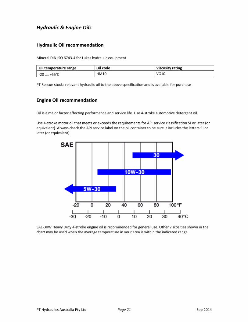
Engine Oil recommendation
Oil is a major factor effecting performance and service life. Use 4-stroke automotive detergent oil. Use 4-stroke motor oil that meets or exceeds the requirements for API service classification SJ or later (or equivalent). Always check the API service label on the oil container to be sure it includes the letters SJ or later (or equivalent)
SAE-30W Heavy Duty 4-stroke engine oil is recommended for general use. Other viscosities shown in the chart may be used when the average temperature in your area is within the indicated range.
PT Hydraulics Australia Pty Ltd Page 22 Sep 2014
Frequently Asked Questions
1. LUKAS twin couplings seem to be leaking?
No, the small amount of hydraulic fluid that may be seen is normal. The LUKAS safety coupling prevents pressure increase inside the tool due to change of temperatures. (+ 1°C = 9bar pressure increase).
2. Is it allowed to cut hinges on vehicles?
Yes it is, however care should be taken during this operation.
3. Is it possible to disconnect and connect twin couplings under load?
Yes. Built-in check valves let the tool remain in position.
To Disconnect: Ensure the pump flow is OFF Release the pressure line first, then the return line (blue)
To Re-Connect: Ensure there is no pressure flow Connect the return line (blue) first, then pressure line
The tool can then be used as normal
4. Why is the maximum spreading force of LSP40 and LSP60 the same?
This was decided upon during the design stage. The important factor about the spreaders is their spreading force within 25mm of the end of the tip. The difference at this point is: LSP40EN: 43.2kN LSP60EN: 62.4kN
5. When and how often should the hydraulic oil be replaced?
There is no hard and fast rule for this. But if the oil is dirty it should be replaced as soon as possible. Most rescue agencies are having their pumps serviced annually and the oil is changed as part of this service.
6. What happens if the mono-coupling is disconnected while the equipment is running?
The mono-coupling permits fast and easy coupling while the equipment is in operation. For this reason it does not have a mechanical interlock. If the mono-coupling is disconnected while the equipment is running, it will immediately seal itself. No oil can leak out and the load maintenance function causes the attached rescue equipment to remain stationary at the point at which it was operating. To continue working with the rescue equipment, simply reconnect the two halves of the coupling.
19 Ricketts Road Mount Waverley Victoria 3195 P: 03 9562 8800 F: 03 9562 8080 Email: [email protected] Website: pthydraulics.com.au

PT Hydraulics Australia Pty Ltd Page 23 Sep 2014
Notes