research article channelmodellingformultiprobeover...
TRANSCRIPT

Hindawi Publishing CorporationInternational Journal of Antennas and PropagationVolume 2012, Article ID 615954, 11 pagesdoi:10.1155/2012/615954
Research Article
Channel Modelling for Multiprobe Over-the-Air MIMO Testing
Pekka Kyosti, Tommi Jamsa, and Jukka-Pekka Nuutinen
Elektrobit Corporation, Wireless Business Segment, Tutkijantie 8, 90590 Oulu, Finland
Correspondence should be addressed to Pekka Kyosti, [email protected]
Received 28 December 2011; Accepted 20 March 2012
Academic Editor: Moray Rumney
Copyright © 2012 Pekka Kyosti et al. This is an open access article distributed under the Creative Commons Attribution License,which permits unrestricted use, distribution, and reproduction in any medium, provided the original work is properly cited.
This paper discusses over-the-air (OTA) test setup for multiple-input-multiple-output (MIMO) capable terminals with emphasison channel modelling. The setup is composed of a fading emulator, an anechoic chamber, and multiple probes. Creation ofa propagation environment inside an anechoic chamber requires unconventional radio channel modelling, namely, a specificmapping of the original models onto the probe antennas. We introduce two novel methods to generate fading emulator channelcoefficients; the prefaded signals synthesis and the plane wave synthesis. To verify both methods we present a set of simulationresults. We also show that the geometric description is a prerequisite for the original channel model.
1. Introduction
To meet the increased consumer demand on high datarate applications—such as music and video downloading,web browsing, and multimedia sharing—multiantenna tech-nology will be widely utilized in mobile terminals nearfuture. New standards such as the 3rd Generation Partner-ship Project (3 GPP) High Speed Downlink Packet Access(HSDPA), Long Term Evolution (LTE), LTE-Advanced, andIEEE 802.16 m specify multiple antenna technology also atmobile terminal, and IEEE 802.11 n and 802.11 ac specifymultiple antennas in Wireless Local Area Network (WLAN)devices. Multiple-input-multiple-Output (MIMO) technol-ogy in wide sense covers any multi antenna technique,such as spatial multiplexing, beam forming, and spatialdiversity. MIMO offers significant increases in data through-put, quality of service (QoS), and cell coverage withoutadditional bandwidth or transmit power. Communicationperformance is improved by exploiting the characteristics ofthe propagation channel in which the device is operating.
In MIMO systems, spatial correlation plays a key role.It depends on both antenna and propagation characteristics.Neither can determine the correlation alone. Therefore, it isnecessary to include both antenna and propagation effectsat the same time when testing multiantenna terminals.MIMO over-the-air (OTA) testing provides solution for thatdemand. Due to the complexity of multiple antenna setups,
flexible, fast, and accurate testing solution is needed to speedup the development process and to ensure the real perfor-mance of the terminal. Foegelle [1] identified the need for anew approach for OTA testing of multiantenna terminals tocomplement the existing OTA test methodologies for singleantenna terminals.
Recently, several different MIMO OTA test methodolo-gies have been proposed in research and standardizationforums. European Cooperation in Science and Technology(COST) action COST2100 [2] has been finished and the finalreport will be published soon [3]. Follower of COST2100,new COST IC1004 action continues the work, and the finalresults are expected in year 2015 [4]. 3GPP MIMO OTAStudy Item is almost finished, and the work will potentiallycontinue in a Work Item [5]. CTIA [6] discusses MIMOOTA as well. In all of these groups, three fundamentallydifferent categories of methodologies have been proposed.The methodologies in the first category are based onanechoic chamber and a number of probe antennas, inwhich the signals are controlled by for example a fadingemulator. The second category provides angular dispersionof multipath signals via a reverberation chamber. The powerangular spectrum is 3D uniform. By using an externalfading emulator, longer delay spread can be achieved.Third, multistage methodology is based on a number ofmeasurement steps to evaluate the OTA performance. In thefirst stage the complex antenna pattern is measured by a

2 International Journal of Antennas and Propagation
traditional anechoic chamber-based antenna measurementsystem, single-input-single-output (SISO) OTA. The secondstage combines the antenna pattern information and thechannel model to calculate the MIMO correlation matricesand antenna power imbalances, which are implemented ina channel emulator to make a conductive measurement ortheoretical capacity calculation. The two first MIMO OTAmethodologies provide a possibility to measure the truemobile terminal performance without using artificial cablingin the test setup. On the contrary, conductive test requiresan RF cable connection, which affect the terminal RF andantenna performance.
MIMO OTA testing based on an anechoic chamber and afading emulator (the first methodology) enables true evalu-ation of the end-user experience of the final product againstrealistic radio channel conditions. It also makes it possibleto change the channel model (scenario) flexibly via software,for example signal angle-of-arrival (AoA) and angle spreadare controllable. All critical parts of the mobile terminaldesign (antennas, RF front end, baseband processing) aretested at once. In traditional conductive testing, as in LTEconformance tests, only certain baseband processing is testedwith predefined correlation characteristics, which omits theantenna effect in testing.
Anechoic chamber-based MIMO OTA enables to testoff-the-shelf products (i.e., end products) in equivalentradio propagation conditions to provide unquestionablecomparisons between the devices under test. In practice, theperformance differences between “golden samples” and massproducts may be large, thus there is a need for end device testsystem that can be used for mass production device testingwithout any cable connections.
This paper describes the anechoic chamber and fadingemulator-based MIMO OTA test methodology. In Section 2the overall system is described. Section 3 discusses and pro-poses channel models for MIMO OTA. Section 4 describeshow the desired channel model is mapped onto the limitednumber of probe antennas. Two novel methods, namely,prefaded signals synthesis and plane wave synthesis, areexplained. Section 5 shows simulation results, and Section 6concludes this paper.
2. Anechoic Chamber and FadingEmulator-Based System
The MIMO OTA test setup, originally described in [7],is based on a fading emulator, an anechoic chamber anda number of OTA antennas. The purpose of the setup isto reproduce time variant electromagnetic field around thedevice under test (DUT) imitating the target MIMO radiochannel model, as accurately as possible. The idea is toapply widely approved channel models like TGn model [8],SCM(E) [9], WINNER [10], or IMT-Advanced [11] on aradiated testing of DUT performance.
The components of OTA performance test setup areillustrated in Figure 1. DUT is in the centre of the anechoicchamber, in an area called test zone or test area, andtransmitting antennas are arranged, for example, uniformly
Uplink signal
BSemulator
Fadingemulator
Anechoic chamber
DUT
OTAantennas
Figure 1: Fading emulator and anechoic chamber based MIMOOTA test set-up.
......
...
Fading emulator
BS emulator
Tx signal
Convolution
Convolution
Convolution
Channel impulseresponse data
OTAantennas
Figure 2: Convolution of Tx signal and radio channel impulseresponse data in the fading emulator.
around the DUT in two or three dimensions. Each of thetransmitting antennas is connected to an output port ofthe fading emulator. Typically a power amplifier, betweena fading emulator output and an OTA probe, is requiredto compensate path loss between the OTA probe and DUT.The communication tester (BS emulator) creates the testsignal, which is fed to the multichannel fading emulator. Theemulator creates the multipath environment including pathdelays, Doppler spread and fast fading. A fading emulatorperforms convolution of Tx signals with channel modelimpulse responses as described in Figure 2. The channelmodels containing directions of departures and arrivals aremapped to emulator so that model allocation correspondsto physical antenna installation in the chamber. Phantomheads, hands, and so forth can be easily added to themeasurement. DUT is assumed to be in the far field regionof the OTA antenna radiation.
In the actual MIMO OTA test of a multiantenna terminalan appropriate performance metric, for example throughput,is collected as a figure of merit. DUT may be rotatedaround one, two, or three rotation axis and the finalperformance may be the average performance over differentDUT orientations. The performance averaged over a numberof DUT orientations is effectively different to, for example,the performance in 3D isotropic scattering environment of areverberation chamber. From mathematics it is well knownthat in general case an average of function values is differentto a function value of averaged function argument.

International Journal of Antennas and Propagation 3
D A1V
A1H
A2V
A3V
A4V
A5V
A6V
A7V
A8V
A2H
A3H
A4H
A5H
A6H
A7H
A8H
Test area
Ring ofOTA antennas
Δθ
Figure 3: Ring of OTA antennas and the test zone.
Typically both downlink and uplink transmissions arerequired in the measurement. An uplink communicationantenna is located inside the anechoic chamber so that itdoes not cause interference problems to downlink. A properuplink antenna would be a circularly polarized antenna withhigh directivity. The antenna is connected to a base station(BS) emulator with a coaxial cable. In the simplest caseno fading or multipath effects are emulated in the uplink.In time division duplex (TDD) systems the uplink radiochannel should be reciprocal to downlink, but TDD caseis not discussed in this paper. A system diagram for TDDMIMO OTA test setup is presented in [12].
OTA antennas must be dual-polarized if also polarizationdimension of the radio channel is considered. Both elementsof a single OTA antenna, radiating orthogonally polarizedsignals, have to be connected to different fading emulatoroutputs. This will guarantee independent fading on differentpolarizations as specified, for example in SCM and WINNERchannel models [10, 13]. An example layout of eight dual-polarized OTA antennas is illustrated in Figure 3 withuniformly spaced probes on a circle, resulting to angularspacing Δθ = 45◦.
The example layout in Figure 3 is of 2D setup. Most of thestandardized radio channel models are two dimensional (2D)in the sense that they use only geometrical xy-coordinates(azimuth plane) [14]. Elevation dimension has been left outbecause the power angular spectrum is typically confinedclose to the horizon. The MIMO OTA setup can be extendedto 3D by installing antennas on, for example, cylindricalor spherical formation. A 3D addendum for IMT-advancedchannel models is given in [14].
The number of required OTA antennas has been dis-cussed in [15, 16] and in various COST 2100 contributions.The final formula is still missing, but the number depends onthe DUT size, the centre frequency, the channel model, the
OTA antenna locations, and the acceptable error level. Thefollowing rule of thumb is given in [15]:
K = 2⌈πD
λ
⌉+ 1, (1)
where K is a number of OTA antennas, [·] denotes round upoperation, D is diameter of the test area as in the Figure 3,and λ is the wavelength.
In a practical setup there may be unintentional reflec-tions of transmitted downlink signals from other OTAantennas. Preliminary measurements of [17] indicate thatthe reflections are not a serious problem for the fieldsynthesis. The average scattering level was 35 dB below theline-of-sight path power with a directive Vivaldi type ofOTA antenna design. In the measurement the observedfrequency range was 1.35–7.25 GHz and the distance fromOTA antenna to the centre of the test area was at minimum 1metre.
3. Geometric Channel Models
There exists a high variety of different kinds of MIMOradio channel models. An overview of models is given in[18]. MIMO radio channel models typically have to coverall the four dimensions of the radio channel, namely, time,frequency, space, and polarization. Thus the models are timevariant, wideband, double directional, and polarimetric. Thetwo most popular classes of MIMO channel models are so-called geometry-based models and correlation matrix basedmodels. Models for example in [10, 11, 13] belong to thegeometric family and in [8] to the family of correlationmatrix based models. In many cases also the correlationmatrix based models have geometric description as an initialstarting point. This is the case also in TGn model.
Geometry based modelling enables separation of propa-gation and antennas. Antenna geometries and field patternscan be defined independent of propagation parameters.Channel realisations are generated with the geometricalprinciple by summing contributions of rays (plane waves)with specific small scale parameters like for example delay,power, angle of arrival (AoA), and angle of departure(AoD). Superposition results to correlation between antennaelements and temporal fading with geometry-dependentDoppler spectrum [10].
A widely approved concept in spatial channel modellingis the concept of “cluster.” A number of rays constitute acluster. In a common terminology the cluster is understoodas a propagation path diffused in space, either or both indelay and angle domains. Typically a cluster is composed of afixed number of rays (sub paths) and has a specific shapedpower angular spectrum, for example, Laplacian function,defined by nominal AoA/AoD and angular spread of arrivaland departure (ASA/ASD). A physical propagation mecha-nism creating clusters is reflection, scattering, or diffractionon a limited sized object in the physical environment, forexample on a corner of a building. A cluster can be composedof, for example, a high number of scattering points onsurface of a building. Each scatterer has characteristics likeAoA, AoD, and complex attenuation coefficients. A single

4 International Journal of Antennas and Propagation
ray of geometric model represents scattering (or reflectionor diffraction) on a single scattering point.
A geometry-based channel model can be composedfrom the following propagation parameters: cluster powers,delays, nominal arrival and departure angles, and anglespreads of clusters on both arrival and departure ends, andcluster cross-polarization power ratios (XPRs). In addition,information of the receiver and transmitter antenna arraysincluding both array geometry and antenna field patterns isrequired. (Note that Rx antennas are not specified in MIMOOTA.) Also either the terminal velocity vector or the clusterDoppler frequency components have to be defined.
In the following we define a system model for horizontalplane (2D) MIMO radio channel based on [10, 13]. Transfermatrix of the MIMO channel is
H(t, τ) =L∑l=1
Hl(t, τ). (2)
It is composed of antenna array response matrices Ftx(Tx),Frx(Rx), and impulse response matrices hl for rays l asfollows:
Hl(t, τ) =∫∫
FTrx
(ϕ)
hl(t, τ,φ,ϕ
)Ftx(φ)dϕdφ. (3)
The channel impulse response of the lth ray is a 2 × 2polarimetric matrix
hl(t, τ,φ,ϕ
)
=⎡⎣α
VVl (t) αVH
l (t)
αHVl (t) αHH
l (t)
⎤⎦δ(τ − τl)δ
(φ − φl
)δ(ϕ− ϕl
).
(4)
Now we introduce the clustered structure of a propagationchannel and replace ray index l with cluster index n andcluster sub path index m. The channel coefficient for achannel from Tx antenna element s to Rx antenna elementu for the cluster n can be modelled as
Hu,s,n(t, τ)
=M∑
m=1
⎡⎣Frx,u,V (ϕn,m)
Frx,u,H(ϕn,m)
⎤⎦T
A
⎡⎣Ftx,s,V
(φn,m
)Ftx,s,H
(φn,m
)⎤⎦
· exp(j2πνn,mt
)δ(τ − τn),
(5)
where νn,m is the Doppler shift of sub path n,m and 2 × 2polarization matrix of scattering coefficients is
A =⎡⎣αVV
n,m αVHn,m
αHVn,m αHH
n,m
⎤⎦. (6)
For example, the coefficient αHVn,m contains phase rotation
and attenuation for vertically polarized incident wave andhorizontally polarized scattered wave of ray m of clustern. Coefficients α are modelled as time invariant in clusterbased geometric models. Phases are typically random andamplitudes are determined by the XPR. Random phases
result always to elliptical polarization. For a line-of-sight pathwith linear polarization the off-diagonal elements of A arezeros and diagonal elements have equal phase.
The presented 2D model can be extended to 3D, byinterpreting angles ϕ and φ as composed of azimuth andelevation components like, for example, ϕ = (ϕaz, ϕel).Elevation angular parameters to extend the model are;elevation angle of arrival (EoA) and departure (EoD), andelevation angle spread of arrival (ESA) and departure (ESD).
Cross-polarization power ratio (XPR) has different def-initions. Here we follow and clarify the definition of [10],where XPR is a pure propagation parameter. XPR forvertically polarized Tx signals is
XPRV = SVV
SHV=∣∣αVV
∣∣2
|αHV |2 , (7)
respectively, XPR for horizontally polarized Tx signals is
XPRH = SHH
SVH=∣∣αHH
∣∣2
|αVH |2 , (8)
where
(a) SVV is the coefficient for scattered power on V-polarization and incident power on V-polarization ofan interacting object (cluster),
(b) SVH is the coefficient for scattered power on V-polarization and incident power on H-polarizationof an interacting object (cluster),
(c) SHV is the coefficient for scattered power on H-polarization and incident power on V-polarization ofan interacting object (cluster),
(d) SHH is the coefficient for scattered power on H-polarization and incident power on H-polarizationof an interacting object (cluster).
Even though XPRV and XPRH are defined separately, it isoften assumed that XPRV = XPRH . This is the assumption,for example, in [10, 11].
3.1. Channel Model Prerequisites for MIMO OTA. Geometricdescription of the propagation and the separation of anten-nas and propagation are essential requirements for the basicradio channel model to be reconstructed to a MIMO OTAtest setup. Pure correlation matrix models are not realizablewith a MIMO OTA setup, because they don not fulfil theseprerequisites. At least the DUT end of the channel modelhas to be specified by angular propagation parameters. Ifsome antenna characteristics are embedded to the channelmodel, which is the case in pure correlation matrix-basedmodel, the model itself assumes some DUT antennas. Thus itis not feasible to measure the real DUT antenna performanceanymore.
TGn channel model [8] is a correlation matrix-basedmodel, but it contains also geometric description. It is pos-sible to reconstruct TGn model to MIMO OTA environmentwith specified Tx (base station) antenna correlation matricesand specified, nongeometry-based, Doppler spectra. This

International Journal of Antennas and Propagation 5
can be done with the method of prefaded signals, but notwith the method of plane wave synthesis. Both methods arediscussed in the next section.
The clustered modelling principle of many MIMOchannel models is a benefit for the method of prefadedsignals. It is not a prerequisite, but it makes the method moreefficient. With clustered channel models the individual raysare not essential, but the clusters they compose. In otherwords, it is not necessary to create a high number of rayswith specific characteristics, but instead to model the sumeffects, like spatial correlation, Doppler spectrum, powerdelay profile, XPR, and so forth, accurately.
4. Synthesis of Propagation Environment
This section describes two alternative methods to generatechannel impulse response data (see Figure 2), to a fadingemulator, to create desired radiated propagation environ-ment within the test volume. The methods are prefadedsignals synthesis and plane wave synthesis. Both methods cancreate statistically equal radiated propagation environmentwithin the test volume. The plane wave synthesis has a pointof view in individual rays (plane waves) while the prefadedsignals synthesis focuses on clusters. The basic componentcreated by the plane wave synthesis is a single plane wave witha specific angle of arrival, Doppler shift and magnitude. Withthe prefaded signals synthesis the basic component is a singlecluster with parameters like nominal AoA, ASA, Dopplerspectrum, and XPR. Methods are described in details in thefollowing sub-sections.
4.1. Prefaded Signals Synthesis. Idea of the prefaded signalssynthesis is to transmit Rayleigh or any other kind offaded signals separately from multiple OTA antennas. Fadingsequences are created independently for each cluster. Clustersare mapped to OTA antennas based on cluster power angularspectrum (PAS) and OTA antenna directions. A single clusteris composed by a number of OTA antennas. Each OTAantenna contributing to the cluster has independent fadingcoefficient sequences with identical statistics. For exampleDoppler spectra of fading patterns of different OTA antennasare identical for a single cluster. Discrete PAS of the singlecluster is formed by allocating power weights on top of OTAantennas i.i.d. fading patterns.
As a summary, Doppler spectrum, amplitude distribu-tion, and Tx antenna and directional characteristics arecreated to the prefaded sequences. XPR and Rx direc-tional characteristics are created by allocating i.i.d. prefadedsequences to a set of OTA antennas with specific powerweights.
The principle of creating clusters, applying a numberof OTA antennas, by superposition of independent fad-ing patterns with direction-dependent powers approximatephysical reality. We may consider OTA antennas as subareasof an scattering object creating the cluster. It is assumed thateach subarea contributes to the cluster fading patterns withidentical statistics. Assuming uncorrelated scattering (US)the subareas create independent fading patterns. Thus we
can create the cluster effect with a set of spatially separatedOTA antennas as far as the DUT antenna aperture is smallwith respect to the OTA antenna angular distance. Moreprecisely, the angular resolution of DUT antenna array hasto be smaller than Δθ in Figure 3.
This approach has at least one unrealistic element. Ina real environment the Doppler spectrum should be angledependent within the cluster. With the proposed methodthe Doppler spectrum is equal on all the OTA antennascomposing the cluster. This effect may be observed by aDUT with directional antenna in the case of cluster with ahigh angular spread. We assume that this effect has negligibleeffect on DUT performance.
Details of creating fading patterns and power weights aredescribed in the following. Here we present purely geometry-based method of creating Rayleigh fading coefficients. Any-how it is possible to apply some other method too, as faras the Rx side directional and polarization characteristicsare known. For example, noise filtering method can beapplied for Rayleig fading. Also, for example, fluorescentlight effects of TGn model can be included in the prefadedcoefficients. The Doppler spectrum may be based on someother definition than geometric.
4.1.1. Per Antenna Fading Patterns. On the prefaded signalssynthesis the fading coefficients are generated based on (5).Now the Rx antenna is unknown, thus Frx is substituted byan ideal OTA antenna pattern. The approximation is validif we use OTA antennas with a high polarization isolationand a flat radiation pattern to the direction of the test zone.A Rayleigh fading pattern for cluster n for a channel fromTx (BS) antenna s to vertically polarized element of OTAantenna k is
HVk,s,n(t, τ)
= γn
M∑m=1
⎡⎣1
0
⎤⎦T
A
⎡⎣Ftx,s,V
(φn,m
)Ftx,s,H
(φn,m
)⎤⎦
· exp(j2πνn,mt
)δ(τ − τn)
√gk,n,
(9)
where γn is an amplitude of cluster n, A is a polarizationmatrix and, gk,n is an antenna power weight. The fadingpattern for the horizontally polarized element is obtainedby changing Rx antenna pattern of (9) to [Frx,k,V Frx,k,H] =[0 1] as
HHk,s,n(t, τ)
= γn
M∑m=1
⎡⎣0
1
⎤⎦T
A
⎡⎣Ftx,s,V
(φn,m
)Ftx,s,H
(φn,m
)⎤⎦
· exp(j2πνn,mt
)δ(τ − τn)
√gk,n.
(10)
Antenna power weights determine, together with OTAantenna directions, a discrete power angular spectrum to the
6 International Journal of Antennas and Propagation
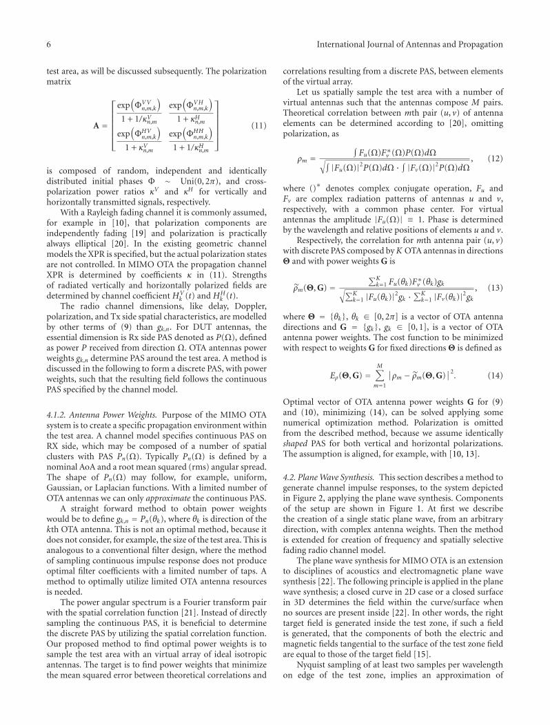
test area, as will be discussed subsequently. The polarizationmatrix
A =
⎡⎢⎢⎢⎢⎢⎣
exp(ΦVV
n,m,k
)
1 + 1/κVn,m
exp(ΦVH
n,m,k
)
1 + κHn,m
exp(ΦHV
n,m,k
)
1 + κVn,m
exp(ΦHH
n,m,k
)
1 + 1/κHn,m
⎤⎥⎥⎥⎥⎥⎦
(11)
is composed of random, independent and identicallydistributed initial phases Φ ∼ Uni(0, 2π), and cross-polarization power ratios κV and κH for vertically andhorizontally transmitted signals, respectively.
With a Rayleigh fading channel it is commonly assumed,for example in [10], that polarization components areindependently fading [19] and polarization is practicallyalways elliptical [20]. In the existing geometric channelmodels the XPR is specified, but the actual polarization statesare not controlled. In MIMO OTA the propagation channelXPR is determined by coefficients κ in (11). Strengthsof radiated vertically and horizontally polarized fields aredetermined by channel coefficient HV
k (t) and HHk (t).
The radio channel dimensions, like delay, Doppler,polarization, and Tx side spatial characteristics, are modelledby other terms of (9) than gk,n. For DUT antennas, theessential dimension is Rx side PAS denoted as P(Ω), definedas power P received from direction Ω. OTA antennas powerweights gk,n determine PAS around the test area. A method isdiscussed in the following to form a discrete PAS, with powerweights, such that the resulting field follows the continuousPAS specified by the channel model.
4.1.2. Antenna Power Weights. Purpose of the MIMO OTAsystem is to create a specific propagation environment withinthe test area. A channel model specifies continuous PAS onRX side, which may be composed of a number of spatialclusters with PAS Pn(Ω). Typically Pn(Ω) is defined by anominal AoA and a root mean squared (rms) angular spread.The shape of Pn(Ω) may follow, for example, uniform,Gaussian, or Laplacian functions. With a limited number ofOTA antennas we can only approximate the continuous PAS.
A straight forward method to obtain power weightswould be to define gk,n = Pn(θk), where θk is direction of thekth OTA antenna. This is not an optimal method, because itdoes not consider, for example, the size of the test area. This isanalogous to a conventional filter design, where the methodof sampling continuous impulse response does not produceoptimal filter coefficients with a limited number of taps. Amethod to optimally utilize limited OTA antenna resourcesis needed.
The power angular spectrum is a Fourier transform pairwith the spatial correlation function [21]. Instead of directlysampling the continuous PAS, it is beneficial to determinethe discrete PAS by utilizing the spatial correlation function.Our proposed method to find optimal power weights is tosample the test area with an virtual array of ideal isotropicantennas. The target is to find power weights that minimizethe mean squared error between theoretical correlations and
correlations resulting from a discrete PAS, between elementsof the virtual array.
Let us spatially sample the test area with a number ofvirtual antennas such that the antennas compose M pairs.Theoretical correlation between mth pair (u, v) of antennaelements can be determined according to [20], omittingpolarization, as
ρm =∫Fu(Ω)F∗v (Ω)P(Ω)dΩ√∫ |Fu(Ω)|2P(Ω)dΩ · ∫ |Fv(Ω)|2P(Ω)dΩ
, (12)
where ()∗ denotes complex conjugate operation, Fu andFv are complex radiation patterns of antennas u and v,respectively, with a common phase center. For virtualantennas the amplitude |Fu(Ω)| ≡ 1. Phase is determinedby the wavelength and relative positions of elements u and v.
Respectively, the correlation for mth antenna pair (u, v)with discrete PAS composed byK OTA antennas in directionsΘ and with power weights G is
ρm(Θ, G) =∑K
k=1 Fu(θk)F∗v (θk)gk√∑Kk=1 |Fu(θk)|2gk ·
∑Kk=1 |Fv(θk)|2gk
, (13)
where Θ = {θk}, θk ∈ [0, 2π] is a vector of OTA antennadirections and G = {gk}, gk ∈ [0, 1], is a vector of OTAantenna power weights. The cost function to be minimizedwith respect to weights G for fixed directions Θ is defined as
Eρ(Θ, G) =M∑
m=1
∣∣ρm − ρm(Θ, G)∣∣2. (14)
Optimal vector of OTA antenna power weights G for (9)and (10), minimizing (14), can be solved applying somenumerical optimization method. Polarization is omittedfrom the described method, because we assume identicallyshaped PAS for both vertical and horizontal polarizations.The assumption is aligned, for example, with [10, 13].
4.2. Plane Wave Synthesis. This section describes a method togenerate channel impulse responses, to the system depictedin Figure 2, applying the plane wave synthesis. Componentsof the setup are shown in Figure 1. At first we describethe creation of a single static plane wave, from an arbitrarydirection, with complex antenna weights. Then the methodis extended for creation of frequency and spatially selectivefading radio channel model.
The plane wave synthesis for MIMO OTA is an extensionto disciplines of acoustics and electromagnetic plane wavesynthesis [22]. The following principle is applied in the planewave synthesis; a closed curve in 2D case or a closed surfacein 3D determines the field within the curve/surface whenno sources are present inside [22]. In other words, the righttarget field is generated inside the test zone, if such a fieldis generated, that the components of both the electric andmagnetic fields tangential to the surface of the test zone fieldare equal to those of the target field [15].
Nyquist sampling of at least two samples per wavelengthon edge of the test zone, implies an approximation of

International Journal of Antennas and Propagation 7
rm
β
v
θκ
ϕ
Figure 4: A single plane wave from AoA ϕ observed in location rm.
required probe numbers [15]. A waveform, observed withina test zone as a single plane wave from an arbitrary direction(angle of arrival AoA), can be created if the angular samplingby OTA antennas is dense enough. This is approximated bythe rule of thumb of (1).
4.2.1. Single Static Plane Wave. As in Figure 4 a plane wavefrom an arbitrary AoA ϕ is created by setting appropriatecomplex antenna weights gk to the CW (continuous waveon carrier frequency) transmitted from OTA antenna k, k =1, . . . ,K . Each OTA antenna may contribute by radiatingwaves. Superposition of waves within the test area is thenobserved as a single plane wave with a specific AoA ϕ.Weights gk can be obtained, for example, by a numericaloptimization. The numerical optimization may, for example,minimize the difference between the target field and theresulting field on the edge of the test area or some othersampling points within the test area. There are variousprocedures to perform the optimization. Here we present amethod based on matrix inversion. The presented method isfor vertically polarized (z-polarized) fields only, but it can beextended to any polarizations.
Weights gk for a single plane wave can be obtained bysolving OTA antenna weight vector G from the followingmatrix equation
FG = T, (15)
where:
(a) F = {αm,k} ∈ CM×K is a transfer matrix ofcoefficients from kth OTA antenna to mth locationrm;
(b) G = {gk} ∈ CK×1 is a vector of OTA antenna complexweights;
(c) T = {ez(rm)} ∈ CM×1 is a vector of complex targetfield values in locations rm (of a plane wave with AoAϕ);
(d) rm is a location vector, pointing from the origin tomth sample point.
The transfer coefficient from kth OTA antenna to mthlocation rm is composed of path loss term L and a phase termas
αm,k = L(dk,m
)exp(− j∥∥∥β∥∥∥dk,m
), (16)
where dk,m = ‖θk + rm‖ is the distance from the kth OTAantenna to mth location, θk is a vector from kth OTA antennato centre of the test area, β is the wave vector pointing fromAoA direction as in Figure 4, ‖β‖ = 2π/λ0, and λ0 is thewavelength at fc. The target field for a plane wave is
ez(rm) = E0 exp(− jβ • rm
), (17)
where field strength E0 ≡ 1 for the target field and • denotesthe scalar product operation.
When both F and T are constructed the vector G can besolved. If M = K , the solution can be computed by matrixinversion
G = F−1T. (18)
In some cases M > K sample points within the test area maybe specified. This leads to an overdetermined optimizationproblem. In this case the target is to minimize squared L2norm [23]
minG‖FG− T‖, (19)
which results to solving G by the pseudo inverse
G =(
FHF)−1
FHT. (20)
Creation of vertical polarizations in 2D MIMO OTAconfiguration can be done with the discussed principles. Forother polarizations or 3D environment the coefficient G haveto be determined for three orthogonal polarizations insteadof just one polarization. The mathematics to derive the costfunction and the optimization for the multipolarized case isexcluded from this paper.
4.2.2. Doppler Shift. In the previous we described how to findchannel coefficients to create a single static plane wave withan arbitrary AoA. Now we introduce Doppler shift to theplane wave to enable time variant radio channels. A virtualmotion of DUT creates Doppler shifts to plane waves. TheDoppler shift to a plane wave with AoA ϕ resulting fromvirtual motion to direction ν, as illustrated in Figure 4, is
ωd = −β • ν. (21)
The Doppler shift can be introduced to the plane wave bymultiplying Doppler frequency component ωd (= 2π fd) tothe complex weights. That is by making the complex weightstime dependent as follows:
wk(t) = gk exp(− jtωd
). (22)

8 International Journal of Antennas and Propagation
Now the received field on an arbitrary location m within thetest area, neglecting the path loss, is
Ez(t, rm)
=K∑k=1
wk(t) exp(− j
(∥∥∥β∥∥∥dk,m + tωc
))
=K∑k=1
gk exp(− j
∥∥∥β∥∥∥dk,m
)exp(− jt(ωd + ωc)
).
(23)
Even though the complex weights wk(t) are time depen-dent, the AoA dependent part (gk) has to be determined onlyonce. Temporal behaviour is generated by multiplying fixedweight with rotating phasor as in (22).
4.2.3. Power Angular Spectrum. A specific power angulardensity function can be formed within the test zone byintroducing a number of plane waves with an appropriateAoA and magnitude. The AoA range may be, for example,sampled uniformly, as in Figure 5(a), with Q plane waves.Appropriate powers Pq, q = 1, . . . ,Q, can be allocated toplane waves according to the target PAS. Another option is tofix powers and sample the angular space nonuniformly suchthat the target PAS is created as illustrated in Figure 5(b). Inboth cases each plane wave q has a specific AoA ϕq and powerPq. Also the Doppler shift ωd,q will be unique for each planewave depending on AoA and velocity vector of the virtualmotion, as specified in (21).
Now the the complex weight of kth OTA antenna will bea sum of contributions to Q plane waves as follows:
wk(t) =Q∑q=1
√Pq gk,q exp
(− jtωd,q
), (24)
where gk,q is solved separately for each plane wave q byminimization of (19).
4.2.4. Delay Dispersion. Delay dispersion is straightforwardto implement in the fading emulator-based setup. Assuminguncorrelated scattering (UC) the fading of each discrete delaycomponent is independent. Thus channel coefficients fordifferent delay taps are generated applying same principlesas when creating a single plane wave and an arbitrary powerangular spectrum.
Polarization characteristics, Tx (base station) antennaeffects, and Tx side spatial characteristics can be includedin the channel impulse responses generated with the planewave synthesis. Description of the method to model thementioned effects is excluded from this paper, but theprinciple is similar to the prefaded signals synthesis.
5. Simulation Results
Measurement and simulation results to verify the conceptof anechoic chamber and fading emulator-based multiprobeMIMO OTA setup are reported in numerous COST 2100,COST IC1004 and 3GPP contributions. Paper [24] presents
experimental and simulated results applying the prefadedsignals method. Verification of a created radio channelwith all its dimensions and characteristics is an extensivetask. Here we show only a selection of simulation figuresto demonstrate the two channel synthesis methods. Thesimulated characteristics are spatial correlation function(SCF), XPR, Doppler power spectrum (DPS), and temporalcorrelation function (TCF). Power delay profile (PDP) isexcluded from the simulations, because creation of PDP is atrivial task with a digital fading emulator. Although the XPRsimulation result illustrates a special case of a PDP.
In the simulations we had 16 uniformly spaced OTAantennas with 22.5◦ angular spacing. OTA antennas wereassumed as omnidirectional vertically polarized probeswith an isotropic radiation pattern. Additional horizontallypolarized probes, co-located with vertically polarized OTAprobes, were present in the XPR simulation. Transmitterantenna (base station) was assumed as ideal omnidirectionalvertically polarized element. In XPR case the target channelmodel contained nine equal power clusters, with 200 nsspacing in delay, and XPRs from −20 dB to + 20 dB with a5 dB increment. In the other cases the channel model was asingle cluster model with AoA = 10◦ and ASA = 15◦. Thedirection of travel was 40◦ and sampling was four samplesper wavelength. At total 50, 000 samples was simulated. Anexception was the Doppler power spectrum and the temporalcorrelation, where 20 samples per wavelength and 250, 000samples was used to make the curves smoother.
5.1. Spatial Correlation. Figure 6 depicts the theoreticalspatial correlation function for a Laplacian function shapedPAS and SCF calculated from channel impulse responsesgenerated with the plane wave synthesis (PWS) and theprefaded signals synthesis (PFS). A time series of channelimpulse responses for each OTA antenna was generated withthe both methods. Then the field Ez(t, rm) over time, alonga segment of line of locations rm was composed. Correlationbetween locations was calculated as the correlation betweenfield coefficients Ez(t, rm) in different locations over time.The examined correlation is an absolute value of a complexcorrelation coefficient. The simulation setup was similar tothe measurement reported in [24].
Spatial correlation is an appropriate measure of thespatial dimension. Power angular spectrum observed by aDUT is inherently discontinuous and any power cannot bereceived from directions in between probes. Thus AoA orPAS estimation is not necessarily a meaningful techniqueto evaluate the created PAS. On the other hand, spatialcorrelation, as a fourier transform pair of PAS [21], is acontinuous function and a good metric to assess the createdspatial field.
The PWS curve (solid red) follows well the theoreticalcurve (blue circles) up to the simulated 1.5 wavelength spatialseparation, as we can observe from the Figure 6. The PFScurve (solid green) follows the theoretical curve up to thesimulated 1.2 wavelength spatial separation and deviatesslightly after that. Anyhow the theoretical correlation on thearea of deviation is low, 0.2, or below, and the deviation

International Journal of Antennas and Propagation 9
Pow
er (
lin.)
−100 −50 0 50 100
AoA (deg)
(a)
Pow
er (
lin.)
−100 −50 0 50 100
AoA (deg)
(b)
Figure 5: Uniform (a) and non-uniform (b) sampling of Laplacian function shaped PAS.
SCF, 16 OTA ant, AoA= 10◦, AS = 15◦
Theor.PWSPFS
Antenna separation (λ)
0 0.5 1 1.50
0.2
0.4
0.6
0.8
1
|corr
elat
ion|
Figure 6: Simulated spatial correlations with 16 probes, AoA = 10◦,and ASA = 15◦.
should have only marginal effect on, for example, channelcapacity. We may conclude that the both channel mappingmethods are capable of creating spatial radio channelcharacteristics according to the target model in the simulatedcase.
5.2. XPR. The polarization dimension is evaluated by inves-tigating XPR values. With this type of geometric modelsthe exact polarization state is not specified, as discussedearlier. Thus it is not feasible to simulate and comparepolarization states. In the simulation a nine-cluster targetmodel was defined, with different per cluster XPR values. The
average power, received by an ideal vertically polarized DUTantenna, is the simulation result. Because Tx (base station)antenna was also vertically polarized ideal element, we getthe simulated XPR directly by observing the Rx power andcompensating out the path loss.
The simulated XPR values, achieved with the PFSmethod, and the target values are presented in the Figure 7.Also the deviation between target and simulation per clusterXPR values is shown. The maximum deviation in thissimulation was below 0.2 dB. In practical measurementthe antenna nonidealities typically preclude this accurateresults. The PWS method was excluded from the polarizationsimulation.
5.3. Doppler and Temporal Correlation. Simulated Dopplerspectra from channel fading patterns generated with the PWSmethod (solid red) and the PFS method (solid green) areshown in Figure 8. The both spectra have similar spiky shape.Due to the nature of ray based geometric modelling it isdifficult to compare the Doppler spectra directly. Especiallyany numerical comparison is practically impossible. Equiv-alent to the angular dimension, it is beneficial to transformspiky Doppler spectrum to a continuous domain of temporalcorrelation function.
TCF is a Fourier transform pair with the Dopplerspectrum [21]. The transformation results to continuousfunction, which can be directly compared to a theoreticalTCF. Such a comparison is depicted in the Figure 9, wherereal values of the complex temporal correlation coefficientare plotted. Temporal separation (delay) Δτ in the figure hasa normalized unit of 1/2 fmax, where fmax is the maximumDoppler frequency component of the fading pattern. We canobserve that the main lobe of the correlation resulting fromboth PWS (solid red) and PFS (solid green) methods followsalmost perfectly the theoretical correlation (blue circles).PWS curve starts to deviate at the second peak of TCF while

10 International Journal of Antennas and Propagation
XPR targetXPR simulated
XP
R (
dB)
−20
0
20
0 500 1000 1500
Delay (ns)
(a)
XPR error
XP
R e
rror
(dB
)
−0.2
0
0.2
0 500 1000 1500
Delay (ns)
(b)
Figure 7: Simulated XPR with prefaded signals synthesis, target XPR is from −20 to +20 dB with 5 dB increments.
DPS, AoA= 10◦, AS = 15◦, = 40◦
−25
−20
−15
−10
−5
0
−2 −1 0 1 2
Mag
nit
ude
(dB
)
PWSPFS
Doppler shift ( f / fmax)
vθ
Figure 8: Simulated Doppler power spectra with 16 probes, AoA =10◦, and ASA = 15◦.
PFS curve has excellent match over the range of simulatedΔτ.
In the simulation we created clusters by a set of plainwaves having uniform arrival angles. Arrival angles deter-mine Doppler shifts by relation ν = fmax cos(ϕ − θv). Theselection of 1◦ uniform angular sampling was probably notthe optimal choice for creating accurate TCF. Some otherangular sampling may have been better. Anyhow, the exactDoppler modelling is not the main focus of our contribution.The topic of defining parameters for a sum of rays basedon temporal modelling is widely investigated by Patzold, forexample, in [25].
6. Discussion
In this paper we discussed the multiprobe MIMO OTA testsystem. We presented two alternatives to create radio prop-agation environment to MIMO OTA system, (1) prefadedapproach and (2) plane wave approach. Both approaches
TCF, AoA= 10◦, AS = 15◦, = 40◦
Theor.PWSPFS
−1
−0.5
0
0.5
1
0 1 2 3 4 5
vθ
(1/Nyquist frequency)
(cor
rela
tion
)
Δt
R
Figure 9: Simulated temporal correlations with 16 probes, AoA =10◦, and ASA = 15◦.
are feasible to generate given radio propagation environmentand we conclude the paper to highlight the pros and cons ofeach approach.
Benefits of the prefaded signals synthesis are; phasecalibration is not required, simplicity, and possibility tocreate non-geometrical Doppler spectra. We recommendprefaded signals synthesis for standard models with wideclusters and Rayleigh fading or Ricean fading with a singleLOS component. The LOS component, typically with a linearpolarization state, can be created by rounding its AoA tothe nearest dual polarized OTA probe. For that purpose theorthogonally polarized OTA antenna elements have to becolocated.
Main benefits of the plane wave synthesis for MIMO OTAcompared to the prefaded signals synthesis are; support forLOS paths between OTA antennas, support for controlledpolarization of paths (e.g., linear, circular, elliptic), andpossibly more flexible support for dynamic (non stationary)

International Journal of Antennas and Propagation 11
channel models. Plane wave synthesis may also compensatedistortion effect resulting from limited physical dimensionsof an OTA antenna ring. These effects are, for example,distortion due to varying path loss and curved phase fronts,as discussed in [26]. A drawback of the plane wave synthesisis the requirement of phase calibration.
Complex weights gk for the plane wave synthesis arefunction of AoA and OTA antenna configuration only. Fora fixed OTA antenna configuration it is possible to pre-calculate weights gk, for example, for one degree grid ofAoA values. In the actual generation of impulse responsedata the weights could be taken from a table and it wouldnot be necessary to calculate them again. This would bea remarkable reduction of computing time in the case ofdynamic channel models with time variant AoA and otherpropagation parameters.
Simulation results indicate that the spatial, polarimetric,and temporal dimensions of a target channel model can becreated with the both methods. Delay dimension is a trivialmodelling with a digital fading emulator applying either ofPWS or PFS methods.
Acknowledgments
The research was partly conducted in the framework theCELTIC Project CP5-026 WINNER+ and partly of a researchproject, abbreviated MIMOTA, funded by the Finnish Fund-ing Agency for Technology and Innovation (Tekes). Theauthors would like to acknowledge the contributions of theircolleagues, especially Mr. Lassi Hentila.
References
[1] M. D. Foegelle, “Over-the-air performance testing of wirelessdevices with multiple antennas,” RF Design, pp. 44–52, 2006.
[2] http://www.cost2100.org/.[3] R. Verdone and A. Zanella, Eds., Pervasive Mobile and Ambient
Wireless Communications: COST Action 2100, Springer, 2012.[4] http://ic1004.org/.[5] Vodafone, “Proposed SID revision for study item: measure-
ment of radiated performance for MIMO and multi-antennareception for HSPA and LTE terminals,” 3GPP TSG-RAN 54,RP-111754, Berlin, Germany, 2011.
[6] http://www.ctia.org/.[7] P. Kyosti, J. Nuutinen, J. Kolu, and M. Falck, “Channel
modelling for radiated testing of MIMO capable terminals,” inProceedings of the ICT-Mobile Summit, Santander, Spain, June2009.
[8] V. Erceg, L. Schumacher, P. Kyritsi et al., “TGn channel models,IEEE P802.11 wireless LANs, http://www.802wirelessworld.com:8802/,” Tech. Rep., IEEE, 2004.
[9] D. S. Baum, J. Hansen, G. del Galdo, M. Milojevic, J. Salo,and P. Kyosti, “An interim channel model for beyond-3Gsystems: extending the 3GPP spatial channel model (SCM),”in Proceedings of the IEEE 61st Vehicular Technology Conference(VTC ’05), vol. 5, pp. 3132–3136, Stockholm, Sweden, May2005.
[10] P. Kyosti, J. Meinila, L. Hentila et al., “IST-4-027756 WINNERII deliverable 1.1.2. v.1.2, WINNER II channel models,” Tech.Rep. IST-WINNER2, 2007.
[11] “Guidelines for evaluation of radio interface technologies forIMTAdvanced, ITU-R Report M.2135,” Tech. Rep., 2008, ITU-R.
[12] J. P. Nuutinen, P. Kyosti, Y. Gao, and M. D. Foegelle, “On theMIMO OTA test system,” in Proceedings of the 5th InternationalICST Conference on Communications and Networking in China(ChinaCom ’10), Beijing, China, August 2010.
[13] 3GPP/3GPP2 TR 25.996 V6.1.0, “Spatial channel model formultiple input multiple output (MIMO) simulations,” Tech.Rep., 2003, 3rd Generation Partnership Project.
[14] L. Hentila, P. Kyosti, and J. Meinila, “Elevation extensionfor a geometry-based radio channel model and its influenceon MIMO antenna correlation and gain imbalance,” inProceedings of the 5th European Conference on Antennas andPropagation (EUCAP ’11), pp. 2175–2179, Rome, Italy, April2011.
[15] T. Laitinen, P. Kyosti, and J. Nuutinen, “On the numberof OTA antenna elements for plane-wave synthesis,” in Pro-ceedings of the 4th European Conference on Antennas andPropagation (EuCAP ’10), Barcelona, Spain, April 2010.
[16] T. Imai, Y. Okano, K. Koshiro, K. Saito, and S. Miura,“Theoretical analysis of adequate number of probe antennasin spatial channel emulator for mimo performance evaluationof mobile terminals,” in Proceedings of the 4th European Con-ference on Antennas and Propagation (EuCAP ’10), Barcelona,Spain, April 2010.
[17] M. Sonkki, V. Hovinen, D. Sanchez-Escuderos, E. Salonen,and M. Ferrando-Bataller, “Scattering properties of widebanddual-polarized vivaldi antenna for MIMO OTA,” in COSTIC1004 TD(12) 03058, Barcelona, Spain, 2012.
[18] P. Almers, E. Bonek, A. Burr et al., “Survey of channeland radio propagation models for wireless MIMO systems,”Eurasip Journal on Wireless Communications and Networking,vol. 2007, Article ID 19070, 2007.
[19] S. R. Saunders, Antennas and Propagation for Wireless Commu-nication Systems, John Wiley & Sons, Chichester, UK, 1999.
[20] R. Vaughan and J. B. Andersen, Channels, Propagation andAntennas for Mobile Communications, IET, London, UK, 2003.
[21] M. Patzold, “System function and characteristic quantitiesof spatial deterministic Gaussian uncorrelated scattering pro-cesses,” in Proceedings of the 57th IEEE Semiannual VehicularTechnology Conference (VTC ’03), pp. 256–261, April 2003.
[22] W. A. T. Kotterman, A. Heuberger, and R. S. Thoma, “On theaccuracy of synthesised wave-fields in MIMO-OTA set-ups,”in Proceedings of the 5th European Conference on Antennas andPropagation (EUCAP ’11), pp. 2560–2564, Rome, Italy, April2011.
[23] G. H. Golub and C. F. van Loan, Matrix Computations, TheJohns Hopkins University Press, Baltimore, Md, USA, 3rdedition, 1996.
[24] P. Kyosti, J. P. Nuutinen, and T. Jamsa, “MIMO OTA testconcept with experimental and simulated verification,” inProceedings of the 4th European Conference on Antennas andPropagation (EuCAP ’10), Barcelona, Spain, April 2010.
[25] M. Patzold, Mobile Fading Channels, John Wiley & Sons,Chichester, UK, 2002.
[26] P. Kyosti and L. Hentila, “Criteria for physical dimensions ofMIMO OTA multi-probe test setup,” in Proceedings of the 6thEuropean Conference on Antennas and Propagation (EuCAP’12), Prague, Czech Republic, March 2012.

International Journal of
AerospaceEngineeringHindawi Publishing Corporationhttp://www.hindawi.com Volume 2010
RoboticsJournal of
Hindawi Publishing Corporationhttp://www.hindawi.com Volume 2014
Hindawi Publishing Corporationhttp://www.hindawi.com Volume 2014
Active and Passive Electronic Components
Control Scienceand Engineering
Journal of
Hindawi Publishing Corporationhttp://www.hindawi.com Volume 2014
International Journal of
RotatingMachinery
Hindawi Publishing Corporationhttp://www.hindawi.com Volume 2014
Hindawi Publishing Corporation http://www.hindawi.com
Journal ofEngineeringVolume 2014
Submit your manuscripts athttp://www.hindawi.com
VLSI Design
Hindawi Publishing Corporationhttp://www.hindawi.com Volume 2014
Hindawi Publishing Corporationhttp://www.hindawi.com Volume 2014
Shock and Vibration
Hindawi Publishing Corporationhttp://www.hindawi.com Volume 2014
Civil EngineeringAdvances in
Acoustics and VibrationAdvances in
Hindawi Publishing Corporationhttp://www.hindawi.com Volume 2014
Hindawi Publishing Corporationhttp://www.hindawi.com Volume 2014
Electrical and Computer Engineering
Journal of
Advances inOptoElectronics
Hindawi Publishing Corporation http://www.hindawi.com
Volume 2014
The Scientific World JournalHindawi Publishing Corporation http://www.hindawi.com Volume 2014
SensorsJournal of
Hindawi Publishing Corporationhttp://www.hindawi.com Volume 2014
Modelling & Simulation in EngineeringHindawi Publishing Corporation http://www.hindawi.com Volume 2014
Hindawi Publishing Corporationhttp://www.hindawi.com Volume 2014
Chemical EngineeringInternational Journal of Antennas and
Propagation
International Journal of
Hindawi Publishing Corporationhttp://www.hindawi.com Volume 2014
Hindawi Publishing Corporationhttp://www.hindawi.com Volume 2014
Navigation and Observation
International Journal of
Hindawi Publishing Corporationhttp://www.hindawi.com Volume 2014
DistributedSensor Networks
International Journal of