research article characteristics of helium gas with high
TRANSCRIPT

Research ArticleCharacteristics of Helium Gas with High Temperatureand High Pressure Flowing through a 90-Degree Elbow
Beibei Feng1 Yanfei Sun1 Xingtuan Yang1 Shengqiang Li1
Jiyuan Tu12 and Shengyao Jiang1
1 Key Laboratory of Advanced Reactor Engineering and Safety Ministry of Education Institute of Nuclear and New Energy TechnologyTsinghua University Beijing 100084 China
2 School of Aerospace Mechanical amp Manufacturing Engineering RMIT University Plenty Road Bundoora VIC 3083 Australia
Correspondence should be addressed to Beibei Feng fengbeibeitsinghuaeducn
Received 27 November 2013 Accepted 6 January 2014 Published 14 April 2014
Academic Editors A R Beig and H Zhang
Copyright copy 2014 Beibei Feng et al This is an open access article distributed under the Creative Commons Attribution Licensewhich permits unrestricted use distribution and reproduction in any medium provided the original work is properly cited
There exists a certain 90∘ elbow structures in the helium circulation ofHTGR-10 In terms of energy-saving and design simplificationof reactorrsquos primary loop 90∘ elbow can be used to measure the helium flow and the content of water vapor both of which aresignificant in an accident It is necessary to make an in-depth research of the flow characteristics of helium flowing 90∘ elbowSimulation results indicate that fluidrsquos motion in the elbow is under the control of the centrifugal forces Static pressure near theextrados is higher than that near the intrados Boundary layer separation occurs at the latter half intrados of the elbow The vortexemerges during the separation process and increases the energy dissipation Velocity in the near-intrados region is higher than thatin the near-extrados region which is opposite to the pressure distribution trend Under the action of the centrifugal forces thesecondary flow emerges in the latter half of the elbow and complicates the flow field by generating two vortexes which rotate in adifferent direction
1 Introduction
High temperature gas-cooled reactor (HTGR) which isdeveloped from gas-cooled reactor and advanced gas-cooledreactor is an advanced type of reactor in nuclear powerreactors High temperature gas-cooled reactor has a lot ofadvantages over traditional rectors such as higher inherentsafety better economy and higher power generation effi-ciency and also the process heat generated by HTGR can beapplied in nuclear hydrogen production [1] and some otherfields The HTGR has the potential to become one of theadvanced reactors which will be upgraded preferentially [2]The primary circuit of high temperature gas-cooled reactorworks with helium as the cooling medium The helium flowthrough the gap between the spherical fuel elements takesaway the heat generated by the fission of U-235 and thentransfers the heat to the steam generator Then the workingfluid of the secondary circuit absorbs the heat energy and
moves the steam turbine workThe system figure of a 10-MWHTGR is shown in Figure 1
The integrality and resistance characteristic of the pri-mary circuit has a significant influence on the safety andeconomy of HTGR The accurate measurement of theheliumrsquos flow and pressure is the precondition for safe andstable operation of the HTGR especially in an accident Atpresent these critical parameters are measured by additionallocal resistance component But additional local resistancecomponents engender some serious harm that goes againstthe safety and economy For example additional local resis-tance components make the force conditions of the circuitpipe more complicated which add additional difficulties tothe design of the primary circuit On the other hand addi-tional local resistance components increase the resistanceof the primary circuit This makes the helium circulatorconsume more power to maintain the forced circulation ofhelium and this is bad for the economy Considering that
Hindawi Publishing CorporationISRN Power EngineeringVolume 2014 Article ID 764283 6 pageshttpdxdoiorg1011552014764283
2 ISRN Power Engineering
Figure 1 The primary circuit of the HTGR-10
there inevitably exist some elbow structures in the primarycircuit as shown in Figure 1 we can make use of the elbow asthe sensing element tomonitor the fluctuation of the heliumrsquosflow and pressure even to measure the steam content mixedin the helium The advantage of doing this is simplifying theforce conditions of the primary circuit and decreasing theresistance by which the design of the primary circuit is lessdifficult than before and the economy is improved
In order to apply the bend sensor to measure heliumrsquosparameter in the HTGRrsquos helium circulation loop the flowcharacteristic of helium in an elbow under the conditionof high temperature and high pressure must be analyzedprofoundly and in detail to research the nature of helium flowin an elbow Liangying and Zhengrong [3 4] analysed theinfluence of elbow parameters on flowmeasurement and dis-cussed the practicability and the reliability of elbow flowme-ter Also the PHOENICS software has been used to simulatethe pressure distribution by Liangying and Zhengrong andthe relationship between the flow and the maximum pressuredifference is in accord with the results of experiments Fromthe viewpoint of improving the measuring method by usingelbow flowmeter Sun et al [5] researched the relationshipbetween the stability of pressure measurement value andpressure measuring point Sunrsquos results showed that when thepressure measuring point is located at the position whichconstitutes an angle of 45 degrees with the outlet cross-section the sensitivity of pressure difference measurementwill be improved and the influence of the secondary flowon measurement correspondingly is reduced Guomin andYi [6] analyzed the feasibility of the use of elbow flowmeterin multiphase flow measurement and design some kinds ofmeasuring method by combining the elbow flowmeter anddensimeter Zhi et al [7] put forward a swirling flow theorymodel based on N-S equation numerical solution whichmade an improvement on the theoretical research of elbowflowmeter based on traditional free swirl theory and forcedswirl theory But the disadvantage of this theory is that alarge number of differential equations have to be solved with
P1 P1 (pressure on the extrados)
P2
P2 (pressure on the intrados)
Bend angle (∘)0 10 20 30 40 50 60 70 80 90
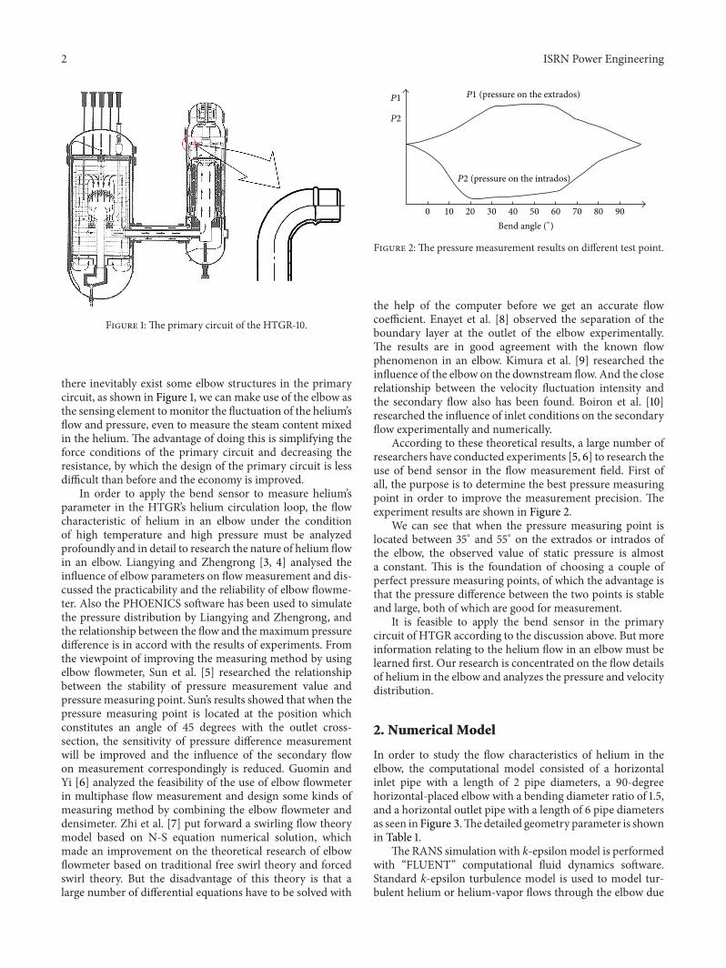
Figure 2 The pressure measurement results on different test point
the help of the computer before we get an accurate flowcoefficient Enayet et al [8] observed the separation of theboundary layer at the outlet of the elbow experimentallyThe results are in good agreement with the known flowphenomenon in an elbow Kimura et al [9] researched theinfluence of the elbow on the downstream flow And the closerelationship between the velocity fluctuation intensity andthe secondary flow also has been found Boiron et al [10]researched the influence of inlet conditions on the secondaryflow experimentally and numerically
According to these theoretical results a large number ofresearchers have conducted experiments [5 6] to research theuse of bend sensor in the flow measurement field First ofall the purpose is to determine the best pressure measuringpoint in order to improve the measurement precision Theexperiment results are shown in Figure 2
We can see that when the pressure measuring point islocated between 35∘ and 55∘ on the extrados or intrados ofthe elbow the observed value of static pressure is almosta constant This is the foundation of choosing a couple ofperfect pressure measuring points of which the advantage isthat the pressure difference between the two points is stableand large both of which are good for measurement
It is feasible to apply the bend sensor in the primarycircuit of HTGR according to the discussion above But moreinformation relating to the helium flow in an elbow must belearned first Our research is concentrated on the flow detailsof helium in the elbow and analyzes the pressure and velocitydistribution
2 Numerical Model
In order to study the flow characteristics of helium in theelbow the computational model consisted of a horizontalinlet pipe with a length of 2 pipe diameters a 90-degreehorizontal-placed elbow with a bending diameter ratio of 15and a horizontal outlet pipe with a length of 6 pipe diametersas seen in Figure 3Thedetailed geometry parameter is shownin Table 1
The RANS simulation with k-epsilonmodel is performedwith ldquoFLUENTrdquo computational fluid dynamics softwareStandard k-epsilon turbulence model is used to model tur-bulent helium or helium-vapor flows through the elbow due
ISRN Power Engineering 3
d
R
L1
L2
Figure 3 The geometry model of the elbow structure
Table 1 The geometry parameter of the structure model
Pipediametermm
Radius ofcurvaturemm 120573 = 119877119889
Inlet pipelength(1198711)
Outletpipelength(1198712)
233 3495 15 3495 10485
Table 2 The results of three refinement solutions
Cell number Dynamic pressurePaMin Max
A 61440 230 4023B 344064 242 4072C 442368 245 4093
Error B to A 56 12C to B 12 05
to its widespread utilization and less consumption and alsogood accuracy
Fully developed turbulent flow is assumed in the horizon-tal inlet section and after the elbow the long outlet pipe canguarantee that the flow of helium will recover to the initialstate A ldquono-sliprdquo boundary condition is employed for thehelium velocity at the wall surface and the thermal conditionsare set in thermal isolation
In order to achieve a good prediction of the flow fieldhexahedralmesh has been used to disperse the computationaldomain The mesh has been refined for many times toeliminate the influence of mesh quality in order to increasethe computational accuracy The three computational resultsof the refinement solution are shown in Table 2
Table 2 tells us that when the cell number of the compu-tational domain changes from 61400 to 344064 the dynamicpressure in the near-wall regionmakes a considerable changeWhile when it changes from 34406 to 442368 the magnitudeof the relative error between the two simulation results is less
(a) Original mesh
(b) Final mesh
Figure 4 The meshing condition of the geometry model
than 2Considering the time-consuming and the acceptablecomputational accuracy the refinement solution of 344064cell number is applied in our simulation
Considering that the pressure gradient varies significantlyin the elbow we refine the mesh again to adapt it to thepressure gradient which is based on the results of preliminarycalculations 10 percent of the maximum of the pressuregradient is set as the refined threshold Then the original andfinal mesh of the symmetry plane both are shown in Figure 4fromwhichwe can see that the nearer to the wall the finer themeshes
The helium has a mass flow of 686 kgs which is setas the inlet boundary condition The temperature is 250centigrade and the global pressure is set as 70 times 106 PaUnder this condition the density of helium is 6442 kgm3and the dynamic viscosity is 2886 times 10minus5 kg(msdots) Standard
4 ISRN Power Engineering
ZX
Y
356e + 01
341e + 01
331e + 01
320e + 01
309e + 01
299e + 01
288e + 01
277e + 01
267e + 01
256e + 01
245e + 01
235e + 01
224e + 01
213e + 01
203e + 01
192e + 01
181e + 01
171e + 01
160e + 01
149e + 01
139e + 01
128e + 01
117e + 01
107e + 01
960e + 00
853e + 00
747e + 00
640e + 00
533e + 00
427e + 00
320e + 00
213e + 00
107e + 00
000e + 00
Figure 5 Velocity contour of helium in the symmetry plane
wall functions have been used in the simulation and the yplus of the near-wall region is between 487 and 2646 underthe condition of the final mesh Reynolds number is about13 times 106 and Dean number is about 75 times 105 both of whichare much larger than that presented in the references
3 Results and Discussion
31 The Velocity Distribution in the Elbow Figure 5 showsthe velocity contour of helium in the symmetry plane Themagnitude of the velocity is shown by colorThe high velocityregion is observed at the intrados of the elbow in the figureand the low velocity region is at the extrados Boundary layerseparation occurred at the latter half intrados of the elbowTo be more precise the separation point exists at the locationjust a little before the elbow outlet (line B) These resultsare qualitatively in good agreement with well-known flowbehavior in the elbow (Enayet et al 1982) [8]
Figures 6 and 7 show the experimental results of Kimuraet al [9] Figure 6 shows the streamline of time averagedvelocity in the cross-section along the center axis of the elbowThe color stands for the magnitude of the velocity which hasbeen normalized by the average velocity in the inlet pipe
Figure 7 shows the time averaged velocity vectors perpen-dicular to the pipe axis at the elbow outlet in the circularcross-section Near the intrados of the pipe (lower side in thefigure) the high velocity region is observed In the circularcross-section the fluid had a component velocity of which thedirection is from the intrados to the extrados of the elbowThe flow corresponds to the high velocity region shown inFigure 6 This flow with high velocity due to the action ofcentrifugal forces originated a biased velocity distributionin the latter pipe Furthermore circumferential flows alongthe pipe wall are also observed These flows resulted in thesecondary flow and biased velocity distribution in the latterpipeThe secondary flow and biased velocity distribution canaffect the flow regime of the latter pipe flow
B998400
A998400
Inlet
Outlet
Outside ofelbow
elbowInside of
minus16
minus10
minus00
A
B VV
m(mdash
)
Figure 6 Time averaged streamline in elbow
Outside of elbow
Inside of elbow
05
00
(V2x + V2
y )05Vm
Figure 7 Time averaged velocity vectors at elbow outlet in circularcross-section
32 The Pressure Distribution in the Elbow Figure 8 showsthe static pressure distribution in the domain Before theelbow the flow is stable and the static pressure is a constantfor all of the cross-section When it comes to the elbow thehelium does a quarter of circular motion due to the restraintof the elbowrsquos inner wall Hence the fluidrsquos motion in theelbow is also under the control of the centrifugal forces
The centrifugal forces are given by the pressure differencebetween two points which are the same in bend radiusdirection but different in bend radius value So we can inferthat static pressure near the extrados is higher than that nearthe intrados The simulation results in Figure 8 rigorouslyconfirm our inference Along the bend radius direction
ISRN Power Engineering 5
7000722
7000447
7000172
6999897
6999622
6999347
6999072
6998797
6998522
6998247
Pres
sure
Figure 8 Pressure contours in the elbow
7000722
7000447
7000172
6999897
6999622
6999347
6999072
6998797
6998522
6998247
Pres
sure
A
B
Figure 9 Pressure contours on the symmetry plane
the static pressure becomes higher with the increase of theradius value The maximum of local static pressure is about7000945 Pa which is located at the extrados of the elbow andthe minimum is about 6998247 Pa located at the intradosThe difference between the two values reaches 2700 Pa
Figure 9 shows the static pressure distribution in thesymmetry plane of the domain We can find that from cross-section A to cross-section B the color of the static pressurecontour varies with the value of bend radius and the biggestfluctuation of static pressure distribution also exists in thisregion because the color difference of the pressure contourwhich stands for pressure difference is at its maximum Asthe influence of the elbow the starting point of flow fieldtransformation of helium emerges before the elbow inletnamely cross-section A as shown in Figure 9 And afterthe elbow outlet namely cross-section B the static pressure
A
B
A
B
Figure 10 The forming process of the second flow
begins to recover to a relatively stable state gradually But dueto the energy dissipation induced by viscous forces and localresistance of elbow the static pressure cannot recover to itsoriginal state So the color near the outlet of the pipe is lighterthan that of the inlet which indicates that the static pressurehas decreased irreversibly
33 The Secondary Flow in the Elbow According to thesimulation the secondary flow has been observed Theforming process of the secondary flow can be illustrated bythe transverse velocity gradient The process is shown inFigure 10 A stands for intrados and B represents extrados
When fluid flows in an elbow as we know velocity fieldnear the intrados is stronger than that near the extradosWhen the fluid does a circular motion effects on near-intrados fluid made by centrifugal forces are more significantthan those on near-extrados Then the core fluid will flowfrom the near-intrados region to the near-extrados regionunder the driving of the centrifugal forces In the near-extrados region the pressure is higher than that of the near-intrados region Hence under the driving of the pressuredifference the fluid will flow back from the near-extradosregion to the near-intrados region Then the secondary flowoccurs and exists in the elbow flow or some other curved-pipe flow Because of this in the elbow pipe flow themain flow along the axis will be overlaid by a secondaryflow which is perpendicular to the axis In the center ofthe pipe the secondary flow direction is from the near-intrados region to the near-extrados region and in the near-wall region the direction is contrary to the former Thesecondary flow complicates the flow field by generating twovortexes which rotate in a different direction Velocity on thecircular cross-section fluctuated greatly due to the secondaryflow The elbow can cause biased velocity distribution andlarge velocity fluctuation with low frequency The formationof the secondary flow needs two foundation conditionsnamely the centrifugal forces field and the shear stressgradient In the elbow pipe flow the formation conditionsare automatically satisfied So the pressure field we measurehas been influenced by the secondary flow In considerationof the significance of accuracy in measurement of nuclear
6 ISRN Power Engineering
engineering the influence of the secondary flow must betaken into account
34 Boundary Layer Separation at the Latter Half Intradosof the Elbow Boundary layer is a thin layer close to objectsurface in which there exist a very large velocity gradient androtation along the normal direction Boundary layer separa-tion has been observed at the latter half intrados of the elbowThe separation process can be described as follows whenfluid flows through a curved surface along the flow directionthe flow field near the wall can be divided into three regionsnamely favorable pressure gradient region zero-pressure-gradient region and the adverse pressure gradient region Infavorable pressure gradient region the fluid element near thewall goes forward by the driving of the pressure differenceThen when it goes into the zero-pressure-gradient regionthe fluid element overcomes the viscous drag by consumingits own kinetic energy and continues to flow forward Andthen the fluid element ingresses the adverse pressure gradientin which the element will decelerate under the action ofviscous force and adverse pressure difference The kineticenergy will be consumed up and the velocity turns to be zeroThen the element will depart from the wall and the spacewill be filled by the retral fluid Vortex emerges during theseparation process and increases the energy dissipation Alsothe pressure field in the elbow is disturbed The boundarylayer separation has a great influence on the flow fieldespecially on the downstream flow field So if the elbowsensor is applied in the measurement system of HTGR-10the boundary layer separation process must be researchedprofoundly
4 Conclusions
An investigation of the flow characteristics of helium flowsafter a 90-degree horizontal elbow under conditions of 70 times106 Pa and 250 centigrade is carried out numerically by usingthe standard k-epsilon turbulence model The simulationresults show that the fluidrsquos motion in the elbow is underthe control of the centrifugal forces The static pressure nearthe extrados is higher than that near the intrados Alongthe bend radius direction the static pressure becomes higherwith the increase of the radius value When the pressuremeasuring point is located between 35∘ and 55∘ on theextrados or intrados the observed value of static pressure isalmost a constant Boundary layer separation occurs at thelatter half intrados of the elbow and has a great influenceon the downstream flow field Vortexes emerge during theseparation process and increase the energy dissipation Thevelocity in the near-intrados region is higher than that inthe near-extrados region which is opposite to the pressuredistribution trend Under the action of the centrifugal forcesthe secondary flow emerges in the latter half of the elbowand complicates the flow field by generating two vortexeswhich rotate in a different direction Velocity on the circularcross-section fluctuated greatly due to the secondary flowThe elbow can cause biased velocity distribution and largevelocity fluctuation with low frequency
So the elbow sensor can be applied to measure heliumrsquosparameter in aHTGR according to the research above But wemust make an in-depth research on the flow characteristicsof helium in an elbow Further study is needed to searchthe nature of helium flow in an elbow Considering thatthere may be a little water vapor existing in helium theflow characteristics of the mixture through the elbow shouldalso be investigated from the viewpoint of two-phase flow toanalyze the influence of the water vapor content on the flowcoefficients and the pressure fluctuation at test point
Conflict of Interests
The authors declare that they have no conflict of interestsregarding the publication of this paper
Acknowledgments
This project is supported by the National Science and Tech-nologyMajor Project (Grant no ZX06901) andTheTribologyScience Fund of State Key Laboratory of Tribology (Grant noSKLTKF12B16)
References
[1] P Zhang Y Bo J Chen and J Xu ldquoNuclear hydrogen pro-duction and high temperature gas-cooled rectorrdquo Journal ofChemical Industry and Engineering vol 55 2004
[2] F Xiaoming and W Jie ldquoThe development of high temperaturegas-cooled reactor in ChinardquoModern Electric Power vol 23 no5 pp 70ndash75 2006
[3] W Liangying and Z Zhengrong ldquoCharacteristics of curvedpipe and their applications in the flowmeasurementrdquo IndustrialHeating vol 4 pp 39ndash41 2000
[4] W Liangying and Z Zhengrong ldquoThe theoretical analysis andexperimental research of the application of elbow flowmeter inthe flow measurementrdquoMeasurement Technique vol 9 pp 32ndash34 2003
[5] Z-Q Sun J-M Zhou and H-J Zhang ldquoNumerical simulationand experimental research on measurement characteristics ofelbow meterrdquo Chinese Journal of Sensors and Actuators vol 20no 6 pp 1412ndash1415 2007
[6] X Guomin and S Yi ldquoThe experimental research of the appli-cation of elbow flowmeter in the measurement of multiphaseflowrdquo Oil-Gasfield Surface Engineering vol 25 no 10 pp 10ndash112006
[7] L Zhi M Xianju and L Shaofeng ldquoTheoretic research onelbow ducts based on the N-S equationrdquo Journal of HebeiPolytechnic University vol 30 no 1 pp 41ndash45 2008
[8] M M Enayet M M Gibson A M K P Taylor and M Yian-neskis ldquoLaser-Doppler measurements of laminar and turbulentflow in a pipe bendrdquo International Journal of Heat and FluidFlow vol 3 no 4 pp 213ndash219 1982
[9] N Kimura H Ogawa and H Kamide ldquoExperimental studyon fluid mixing phenomena in T-pipe junction with upstreamelbowrdquo Nuclear Engineering and Design vol 240 no 10 pp3055ndash3066 2010
[10] O Boiron V Deplano and R Pelissier ldquoExperimental andnumerical studies on the starting effect on the secondary flow ina bendrdquo Journal of Fluid Mechanics vol 574 pp 109ndash129 2007
International Journal of
AerospaceEngineeringHindawi Publishing Corporationhttpwwwhindawicom Volume 2014
RoboticsJournal of
Hindawi Publishing Corporationhttpwwwhindawicom Volume 2014
Hindawi Publishing Corporationhttpwwwhindawicom Volume 2014
Active and Passive Electronic Components
Control Scienceand Engineering
Journal of
Hindawi Publishing Corporationhttpwwwhindawicom Volume 2014
International Journal of
RotatingMachinery
Hindawi Publishing Corporationhttpwwwhindawicom Volume 2014
Hindawi Publishing Corporation httpwwwhindawicom
Journal ofEngineeringVolume 2014
Submit your manuscripts athttpwwwhindawicom
VLSI Design
Hindawi Publishing Corporationhttpwwwhindawicom Volume 2014
Hindawi Publishing Corporationhttpwwwhindawicom Volume 2014
Shock and Vibration
Hindawi Publishing Corporationhttpwwwhindawicom Volume 2014
Civil EngineeringAdvances in
Acoustics and VibrationAdvances in
Hindawi Publishing Corporationhttpwwwhindawicom Volume 2014
Hindawi Publishing Corporationhttpwwwhindawicom Volume 2014
Electrical and Computer Engineering
Journal of
Advances inOptoElectronics
Hindawi Publishing Corporation httpwwwhindawicom
Volume 2014
The Scientific World JournalHindawi Publishing Corporation httpwwwhindawicom Volume 2014
SensorsJournal of
Hindawi Publishing Corporationhttpwwwhindawicom Volume 2014
Modelling amp Simulation in EngineeringHindawi Publishing Corporation httpwwwhindawicom Volume 2014
Hindawi Publishing Corporationhttpwwwhindawicom Volume 2014
Chemical EngineeringInternational Journal of Antennas and
Propagation
International Journal of
Hindawi Publishing Corporationhttpwwwhindawicom Volume 2014
Hindawi Publishing Corporationhttpwwwhindawicom Volume 2014
Navigation and Observation
International Journal of
Hindawi Publishing Corporationhttpwwwhindawicom Volume 2014
DistributedSensor Networks
International Journal of
2 ISRN Power Engineering
Figure 1 The primary circuit of the HTGR-10
there inevitably exist some elbow structures in the primarycircuit as shown in Figure 1 we can make use of the elbow asthe sensing element tomonitor the fluctuation of the heliumrsquosflow and pressure even to measure the steam content mixedin the helium The advantage of doing this is simplifying theforce conditions of the primary circuit and decreasing theresistance by which the design of the primary circuit is lessdifficult than before and the economy is improved
In order to apply the bend sensor to measure heliumrsquosparameter in the HTGRrsquos helium circulation loop the flowcharacteristic of helium in an elbow under the conditionof high temperature and high pressure must be analyzedprofoundly and in detail to research the nature of helium flowin an elbow Liangying and Zhengrong [3 4] analysed theinfluence of elbow parameters on flowmeasurement and dis-cussed the practicability and the reliability of elbow flowme-ter Also the PHOENICS software has been used to simulatethe pressure distribution by Liangying and Zhengrong andthe relationship between the flow and the maximum pressuredifference is in accord with the results of experiments Fromthe viewpoint of improving the measuring method by usingelbow flowmeter Sun et al [5] researched the relationshipbetween the stability of pressure measurement value andpressure measuring point Sunrsquos results showed that when thepressure measuring point is located at the position whichconstitutes an angle of 45 degrees with the outlet cross-section the sensitivity of pressure difference measurementwill be improved and the influence of the secondary flowon measurement correspondingly is reduced Guomin andYi [6] analyzed the feasibility of the use of elbow flowmeterin multiphase flow measurement and design some kinds ofmeasuring method by combining the elbow flowmeter anddensimeter Zhi et al [7] put forward a swirling flow theorymodel based on N-S equation numerical solution whichmade an improvement on the theoretical research of elbowflowmeter based on traditional free swirl theory and forcedswirl theory But the disadvantage of this theory is that alarge number of differential equations have to be solved with
P1 P1 (pressure on the extrados)
P2
P2 (pressure on the intrados)
Bend angle (∘)0 10 20 30 40 50 60 70 80 90
Figure 2 The pressure measurement results on different test point
the help of the computer before we get an accurate flowcoefficient Enayet et al [8] observed the separation of theboundary layer at the outlet of the elbow experimentallyThe results are in good agreement with the known flowphenomenon in an elbow Kimura et al [9] researched theinfluence of the elbow on the downstream flow And the closerelationship between the velocity fluctuation intensity andthe secondary flow also has been found Boiron et al [10]researched the influence of inlet conditions on the secondaryflow experimentally and numerically
According to these theoretical results a large number ofresearchers have conducted experiments [5 6] to research theuse of bend sensor in the flow measurement field First ofall the purpose is to determine the best pressure measuringpoint in order to improve the measurement precision Theexperiment results are shown in Figure 2
We can see that when the pressure measuring point islocated between 35∘ and 55∘ on the extrados or intrados ofthe elbow the observed value of static pressure is almosta constant This is the foundation of choosing a couple ofperfect pressure measuring points of which the advantage isthat the pressure difference between the two points is stableand large both of which are good for measurement
It is feasible to apply the bend sensor in the primarycircuit of HTGR according to the discussion above But moreinformation relating to the helium flow in an elbow must belearned first Our research is concentrated on the flow detailsof helium in the elbow and analyzes the pressure and velocitydistribution
2 Numerical Model
In order to study the flow characteristics of helium in theelbow the computational model consisted of a horizontalinlet pipe with a length of 2 pipe diameters a 90-degreehorizontal-placed elbow with a bending diameter ratio of 15and a horizontal outlet pipe with a length of 6 pipe diametersas seen in Figure 3Thedetailed geometry parameter is shownin Table 1
The RANS simulation with k-epsilonmodel is performedwith ldquoFLUENTrdquo computational fluid dynamics softwareStandard k-epsilon turbulence model is used to model tur-bulent helium or helium-vapor flows through the elbow due
ISRN Power Engineering 3
d
R
L1
L2
Figure 3 The geometry model of the elbow structure
Table 1 The geometry parameter of the structure model
Pipediametermm
Radius ofcurvaturemm 120573 = 119877119889
Inlet pipelength(1198711)
Outletpipelength(1198712)
233 3495 15 3495 10485
Table 2 The results of three refinement solutions
Cell number Dynamic pressurePaMin Max
A 61440 230 4023B 344064 242 4072C 442368 245 4093
Error B to A 56 12C to B 12 05
to its widespread utilization and less consumption and alsogood accuracy
Fully developed turbulent flow is assumed in the horizon-tal inlet section and after the elbow the long outlet pipe canguarantee that the flow of helium will recover to the initialstate A ldquono-sliprdquo boundary condition is employed for thehelium velocity at the wall surface and the thermal conditionsare set in thermal isolation
In order to achieve a good prediction of the flow fieldhexahedralmesh has been used to disperse the computationaldomain The mesh has been refined for many times toeliminate the influence of mesh quality in order to increasethe computational accuracy The three computational resultsof the refinement solution are shown in Table 2
Table 2 tells us that when the cell number of the compu-tational domain changes from 61400 to 344064 the dynamicpressure in the near-wall regionmakes a considerable changeWhile when it changes from 34406 to 442368 the magnitudeof the relative error between the two simulation results is less
(a) Original mesh
(b) Final mesh
Figure 4 The meshing condition of the geometry model
than 2Considering the time-consuming and the acceptablecomputational accuracy the refinement solution of 344064cell number is applied in our simulation
Considering that the pressure gradient varies significantlyin the elbow we refine the mesh again to adapt it to thepressure gradient which is based on the results of preliminarycalculations 10 percent of the maximum of the pressuregradient is set as the refined threshold Then the original andfinal mesh of the symmetry plane both are shown in Figure 4fromwhichwe can see that the nearer to the wall the finer themeshes
The helium has a mass flow of 686 kgs which is setas the inlet boundary condition The temperature is 250centigrade and the global pressure is set as 70 times 106 PaUnder this condition the density of helium is 6442 kgm3and the dynamic viscosity is 2886 times 10minus5 kg(msdots) Standard
4 ISRN Power Engineering
ZX
Y
356e + 01
341e + 01
331e + 01
320e + 01
309e + 01
299e + 01
288e + 01
277e + 01
267e + 01
256e + 01
245e + 01
235e + 01
224e + 01
213e + 01
203e + 01
192e + 01
181e + 01
171e + 01
160e + 01
149e + 01
139e + 01
128e + 01
117e + 01
107e + 01
960e + 00
853e + 00
747e + 00
640e + 00
533e + 00
427e + 00
320e + 00
213e + 00
107e + 00
000e + 00
Figure 5 Velocity contour of helium in the symmetry plane
wall functions have been used in the simulation and the yplus of the near-wall region is between 487 and 2646 underthe condition of the final mesh Reynolds number is about13 times 106 and Dean number is about 75 times 105 both of whichare much larger than that presented in the references
3 Results and Discussion
31 The Velocity Distribution in the Elbow Figure 5 showsthe velocity contour of helium in the symmetry plane Themagnitude of the velocity is shown by colorThe high velocityregion is observed at the intrados of the elbow in the figureand the low velocity region is at the extrados Boundary layerseparation occurred at the latter half intrados of the elbowTo be more precise the separation point exists at the locationjust a little before the elbow outlet (line B) These resultsare qualitatively in good agreement with well-known flowbehavior in the elbow (Enayet et al 1982) [8]
Figures 6 and 7 show the experimental results of Kimuraet al [9] Figure 6 shows the streamline of time averagedvelocity in the cross-section along the center axis of the elbowThe color stands for the magnitude of the velocity which hasbeen normalized by the average velocity in the inlet pipe
Figure 7 shows the time averaged velocity vectors perpen-dicular to the pipe axis at the elbow outlet in the circularcross-section Near the intrados of the pipe (lower side in thefigure) the high velocity region is observed In the circularcross-section the fluid had a component velocity of which thedirection is from the intrados to the extrados of the elbowThe flow corresponds to the high velocity region shown inFigure 6 This flow with high velocity due to the action ofcentrifugal forces originated a biased velocity distributionin the latter pipe Furthermore circumferential flows alongthe pipe wall are also observed These flows resulted in thesecondary flow and biased velocity distribution in the latterpipeThe secondary flow and biased velocity distribution canaffect the flow regime of the latter pipe flow
B998400
A998400
Inlet
Outlet
Outside ofelbow
elbowInside of
minus16
minus10
minus00
A
B VV
m(mdash
)
Figure 6 Time averaged streamline in elbow
Outside of elbow
Inside of elbow
05
00
(V2x + V2
y )05Vm
Figure 7 Time averaged velocity vectors at elbow outlet in circularcross-section
32 The Pressure Distribution in the Elbow Figure 8 showsthe static pressure distribution in the domain Before theelbow the flow is stable and the static pressure is a constantfor all of the cross-section When it comes to the elbow thehelium does a quarter of circular motion due to the restraintof the elbowrsquos inner wall Hence the fluidrsquos motion in theelbow is also under the control of the centrifugal forces
The centrifugal forces are given by the pressure differencebetween two points which are the same in bend radiusdirection but different in bend radius value So we can inferthat static pressure near the extrados is higher than that nearthe intrados The simulation results in Figure 8 rigorouslyconfirm our inference Along the bend radius direction
ISRN Power Engineering 5
7000722
7000447
7000172
6999897
6999622
6999347
6999072
6998797
6998522
6998247
Pres
sure
Figure 8 Pressure contours in the elbow
7000722
7000447
7000172
6999897
6999622
6999347
6999072
6998797
6998522
6998247
Pres
sure
A
B
Figure 9 Pressure contours on the symmetry plane
the static pressure becomes higher with the increase of theradius value The maximum of local static pressure is about7000945 Pa which is located at the extrados of the elbow andthe minimum is about 6998247 Pa located at the intradosThe difference between the two values reaches 2700 Pa
Figure 9 shows the static pressure distribution in thesymmetry plane of the domain We can find that from cross-section A to cross-section B the color of the static pressurecontour varies with the value of bend radius and the biggestfluctuation of static pressure distribution also exists in thisregion because the color difference of the pressure contourwhich stands for pressure difference is at its maximum Asthe influence of the elbow the starting point of flow fieldtransformation of helium emerges before the elbow inletnamely cross-section A as shown in Figure 9 And afterthe elbow outlet namely cross-section B the static pressure
A
B
A
B
Figure 10 The forming process of the second flow
begins to recover to a relatively stable state gradually But dueto the energy dissipation induced by viscous forces and localresistance of elbow the static pressure cannot recover to itsoriginal state So the color near the outlet of the pipe is lighterthan that of the inlet which indicates that the static pressurehas decreased irreversibly
33 The Secondary Flow in the Elbow According to thesimulation the secondary flow has been observed Theforming process of the secondary flow can be illustrated bythe transverse velocity gradient The process is shown inFigure 10 A stands for intrados and B represents extrados
When fluid flows in an elbow as we know velocity fieldnear the intrados is stronger than that near the extradosWhen the fluid does a circular motion effects on near-intrados fluid made by centrifugal forces are more significantthan those on near-extrados Then the core fluid will flowfrom the near-intrados region to the near-extrados regionunder the driving of the centrifugal forces In the near-extrados region the pressure is higher than that of the near-intrados region Hence under the driving of the pressuredifference the fluid will flow back from the near-extradosregion to the near-intrados region Then the secondary flowoccurs and exists in the elbow flow or some other curved-pipe flow Because of this in the elbow pipe flow themain flow along the axis will be overlaid by a secondaryflow which is perpendicular to the axis In the center ofthe pipe the secondary flow direction is from the near-intrados region to the near-extrados region and in the near-wall region the direction is contrary to the former Thesecondary flow complicates the flow field by generating twovortexes which rotate in a different direction Velocity on thecircular cross-section fluctuated greatly due to the secondaryflow The elbow can cause biased velocity distribution andlarge velocity fluctuation with low frequency The formationof the secondary flow needs two foundation conditionsnamely the centrifugal forces field and the shear stressgradient In the elbow pipe flow the formation conditionsare automatically satisfied So the pressure field we measurehas been influenced by the secondary flow In considerationof the significance of accuracy in measurement of nuclear
6 ISRN Power Engineering
engineering the influence of the secondary flow must betaken into account
34 Boundary Layer Separation at the Latter Half Intradosof the Elbow Boundary layer is a thin layer close to objectsurface in which there exist a very large velocity gradient androtation along the normal direction Boundary layer separa-tion has been observed at the latter half intrados of the elbowThe separation process can be described as follows whenfluid flows through a curved surface along the flow directionthe flow field near the wall can be divided into three regionsnamely favorable pressure gradient region zero-pressure-gradient region and the adverse pressure gradient region Infavorable pressure gradient region the fluid element near thewall goes forward by the driving of the pressure differenceThen when it goes into the zero-pressure-gradient regionthe fluid element overcomes the viscous drag by consumingits own kinetic energy and continues to flow forward Andthen the fluid element ingresses the adverse pressure gradientin which the element will decelerate under the action ofviscous force and adverse pressure difference The kineticenergy will be consumed up and the velocity turns to be zeroThen the element will depart from the wall and the spacewill be filled by the retral fluid Vortex emerges during theseparation process and increases the energy dissipation Alsothe pressure field in the elbow is disturbed The boundarylayer separation has a great influence on the flow fieldespecially on the downstream flow field So if the elbowsensor is applied in the measurement system of HTGR-10the boundary layer separation process must be researchedprofoundly
4 Conclusions
An investigation of the flow characteristics of helium flowsafter a 90-degree horizontal elbow under conditions of 70 times106 Pa and 250 centigrade is carried out numerically by usingthe standard k-epsilon turbulence model The simulationresults show that the fluidrsquos motion in the elbow is underthe control of the centrifugal forces The static pressure nearthe extrados is higher than that near the intrados Alongthe bend radius direction the static pressure becomes higherwith the increase of the radius value When the pressuremeasuring point is located between 35∘ and 55∘ on theextrados or intrados the observed value of static pressure isalmost a constant Boundary layer separation occurs at thelatter half intrados of the elbow and has a great influenceon the downstream flow field Vortexes emerge during theseparation process and increase the energy dissipation Thevelocity in the near-intrados region is higher than that inthe near-extrados region which is opposite to the pressuredistribution trend Under the action of the centrifugal forcesthe secondary flow emerges in the latter half of the elbowand complicates the flow field by generating two vortexeswhich rotate in a different direction Velocity on the circularcross-section fluctuated greatly due to the secondary flowThe elbow can cause biased velocity distribution and largevelocity fluctuation with low frequency
So the elbow sensor can be applied to measure heliumrsquosparameter in aHTGR according to the research above But wemust make an in-depth research on the flow characteristicsof helium in an elbow Further study is needed to searchthe nature of helium flow in an elbow Considering thatthere may be a little water vapor existing in helium theflow characteristics of the mixture through the elbow shouldalso be investigated from the viewpoint of two-phase flow toanalyze the influence of the water vapor content on the flowcoefficients and the pressure fluctuation at test point
Conflict of Interests
The authors declare that they have no conflict of interestsregarding the publication of this paper
Acknowledgments
This project is supported by the National Science and Tech-nologyMajor Project (Grant no ZX06901) andTheTribologyScience Fund of State Key Laboratory of Tribology (Grant noSKLTKF12B16)
References
[1] P Zhang Y Bo J Chen and J Xu ldquoNuclear hydrogen pro-duction and high temperature gas-cooled rectorrdquo Journal ofChemical Industry and Engineering vol 55 2004
[2] F Xiaoming and W Jie ldquoThe development of high temperaturegas-cooled reactor in ChinardquoModern Electric Power vol 23 no5 pp 70ndash75 2006
[3] W Liangying and Z Zhengrong ldquoCharacteristics of curvedpipe and their applications in the flowmeasurementrdquo IndustrialHeating vol 4 pp 39ndash41 2000
[4] W Liangying and Z Zhengrong ldquoThe theoretical analysis andexperimental research of the application of elbow flowmeter inthe flow measurementrdquoMeasurement Technique vol 9 pp 32ndash34 2003
[5] Z-Q Sun J-M Zhou and H-J Zhang ldquoNumerical simulationand experimental research on measurement characteristics ofelbow meterrdquo Chinese Journal of Sensors and Actuators vol 20no 6 pp 1412ndash1415 2007
[6] X Guomin and S Yi ldquoThe experimental research of the appli-cation of elbow flowmeter in the measurement of multiphaseflowrdquo Oil-Gasfield Surface Engineering vol 25 no 10 pp 10ndash112006
[7] L Zhi M Xianju and L Shaofeng ldquoTheoretic research onelbow ducts based on the N-S equationrdquo Journal of HebeiPolytechnic University vol 30 no 1 pp 41ndash45 2008
[8] M M Enayet M M Gibson A M K P Taylor and M Yian-neskis ldquoLaser-Doppler measurements of laminar and turbulentflow in a pipe bendrdquo International Journal of Heat and FluidFlow vol 3 no 4 pp 213ndash219 1982
[9] N Kimura H Ogawa and H Kamide ldquoExperimental studyon fluid mixing phenomena in T-pipe junction with upstreamelbowrdquo Nuclear Engineering and Design vol 240 no 10 pp3055ndash3066 2010
[10] O Boiron V Deplano and R Pelissier ldquoExperimental andnumerical studies on the starting effect on the secondary flow ina bendrdquo Journal of Fluid Mechanics vol 574 pp 109ndash129 2007
International Journal of
AerospaceEngineeringHindawi Publishing Corporationhttpwwwhindawicom Volume 2014
RoboticsJournal of
Hindawi Publishing Corporationhttpwwwhindawicom Volume 2014
Hindawi Publishing Corporationhttpwwwhindawicom Volume 2014
Active and Passive Electronic Components
Control Scienceand Engineering
Journal of
Hindawi Publishing Corporationhttpwwwhindawicom Volume 2014
International Journal of
RotatingMachinery
Hindawi Publishing Corporationhttpwwwhindawicom Volume 2014
Hindawi Publishing Corporation httpwwwhindawicom
Journal ofEngineeringVolume 2014
Submit your manuscripts athttpwwwhindawicom
VLSI Design
Hindawi Publishing Corporationhttpwwwhindawicom Volume 2014
Hindawi Publishing Corporationhttpwwwhindawicom Volume 2014
Shock and Vibration
Hindawi Publishing Corporationhttpwwwhindawicom Volume 2014
Civil EngineeringAdvances in
Acoustics and VibrationAdvances in
Hindawi Publishing Corporationhttpwwwhindawicom Volume 2014
Hindawi Publishing Corporationhttpwwwhindawicom Volume 2014
Electrical and Computer Engineering
Journal of
Advances inOptoElectronics
Hindawi Publishing Corporation httpwwwhindawicom
Volume 2014
The Scientific World JournalHindawi Publishing Corporation httpwwwhindawicom Volume 2014
SensorsJournal of
Hindawi Publishing Corporationhttpwwwhindawicom Volume 2014
Modelling amp Simulation in EngineeringHindawi Publishing Corporation httpwwwhindawicom Volume 2014
Hindawi Publishing Corporationhttpwwwhindawicom Volume 2014
Chemical EngineeringInternational Journal of Antennas and
Propagation
International Journal of
Hindawi Publishing Corporationhttpwwwhindawicom Volume 2014
Hindawi Publishing Corporationhttpwwwhindawicom Volume 2014
Navigation and Observation
International Journal of
Hindawi Publishing Corporationhttpwwwhindawicom Volume 2014
DistributedSensor Networks
International Journal of

International Journal of
AerospaceEngineeringHindawi Publishing Corporationhttpwwwhindawicom Volume 2014
RoboticsJournal of
Hindawi Publishing Corporationhttpwwwhindawicom Volume 2014
Hindawi Publishing Corporationhttpwwwhindawicom Volume 2014
Active and Passive Electronic Components
Control Scienceand Engineering
Journal of
Hindawi Publishing Corporationhttpwwwhindawicom Volume 2014
International Journal of
RotatingMachinery
Hindawi Publishing Corporationhttpwwwhindawicom Volume 2014
Hindawi Publishing Corporation httpwwwhindawicom
Journal ofEngineeringVolume 2014
Submit your manuscripts athttpwwwhindawicom
VLSI Design
Hindawi Publishing Corporationhttpwwwhindawicom Volume 2014
Hindawi Publishing Corporationhttpwwwhindawicom Volume 2014
Shock and Vibration
Hindawi Publishing Corporationhttpwwwhindawicom Volume 2014
Civil EngineeringAdvances in
Acoustics and VibrationAdvances in
Hindawi Publishing Corporationhttpwwwhindawicom Volume 2014
Hindawi Publishing Corporationhttpwwwhindawicom Volume 2014
Electrical and Computer Engineering
Journal of
Advances inOptoElectronics
Hindawi Publishing Corporation httpwwwhindawicom
Volume 2014
The Scientific World JournalHindawi Publishing Corporation httpwwwhindawicom Volume 2014
SensorsJournal of
Hindawi Publishing Corporationhttpwwwhindawicom Volume 2014
Modelling amp Simulation in EngineeringHindawi Publishing Corporation httpwwwhindawicom Volume 2014
Hindawi Publishing Corporationhttpwwwhindawicom Volume 2014
Chemical EngineeringInternational Journal of Antennas and
Propagation
International Journal of
Hindawi Publishing Corporationhttpwwwhindawicom Volume 2014
Hindawi Publishing Corporationhttpwwwhindawicom Volume 2014
Navigation and Observation
International Journal of
Hindawi Publishing Corporationhttpwwwhindawicom Volume 2014
DistributedSensor Networks
International Journal of