research article conformal patch antenna arrays...
TRANSCRIPT

Hindawi Publishing CorporationAdvances in Power ElectronicsVolume 2013, Article ID 960514, 5 pageshttp://dx.doi.org/10.1155/2013/960514
Research ArticleConformal Patch Antenna Arrays Design for Onboard ShipDeployment Using Genetic Algorithms
Stelios A. Mitilineos,1 Symeon K. Symeonidis,1 Ioannis B. Mpatsis,2 Dimitrios Iliopoulos,1
Georgios S. Kliros,3 Stylianos P. Savaidis,1 and Nikolaos A. Stathopoulos1
1 Technologial Educational Institute of Piraeus, Department of Electronics, 250, Petrou Ralli kai Thivon Street, 12244 Aigaleo, Greece2Hellenic Air Force Academy, Dekeleia Air-Force Base, Dekeleia, Greece3 Department of Aeronautical Sciences, Hellenic Air Force Academy, Dekeleia Air-Force Base, Dekeleia, Greece
Correspondence should be addressed to Stelios A. Mitilineos; [email protected]
Received 17 October 2012; Accepted 17 February 2013
Academic Editor: John Prousalidis
Copyright © 2013 Stelios A. Mitilineos et al. This is an open access article distributed under the Creative Commons AttributionLicense, which permits unrestricted use, distribution, and reproduction in any medium, provided the original work is properlycited.
Conformal antennas and antenna arrays (arrays) have become necessary for vehicular communications where a high degree ofaerodynamic drag reduction is needed, like in avionics and ships. However, the necessity to conform to a predefined shape (e.g.,of an aircraft’s nose) directly affects antenna performance since it imposes strict constraints to the antenna array’s shape, elementspacing, relative signal phase, and so forth. Thereupon, it is necessary to investigate counterintuitive and arbitrary antenna shapesin order to compensate for these constraints. Since there does not exist any available theoretical frame for designing and developingarbitrary-shape antennas in a straightforward manner, we have developed a platform combining a genetic algorithm-based design,optimization suite, and an electromagnetic simulator for designing patch antennas with a shape that is not a priori known (thegenetic algorithm optimizes the shape of the patch antenna). The proposed platform is further enhanced by the ability to designand optimize antenna arrays and is intended to be used for the design of a series of antennas including conformal antennas forshipping applications. The flexibility and performance of the proposed platform are demonstrated herein via the design of a high-performance GPS patch antenna.
1. Introduction
Conformal antennas and antenna arrays (arrays) inherit theirname from the fact that they “conform” to the shape of a 2Dyet not planar surface. More specifically, conformal antennasare flat curving antennas that follow or are embedded toan object of predefined shape, like that of an aircraft’snose. Conformal antennas and antenna arrays (arrays) havebecome necessary for vehicular communications (where ahigh degree of aerodynamic drag reduction is needed) due totheir so-called “conformity” to arbitrary surface shape, like inavionics and high-performance ships or submarines.
Conformal antennas were developed in the 1980s in orderto be integratedwith the outermetallic layers of aircrafts, withthe purpose of reducing the aerodynamic drag and improvingaircraft speed, fuel consumption, and gas emissions. Con-formal antennas gradually replaced conventional ones that
project from the aircrafts’ hull. As long as commercial appli-cations are considered (including shipping), the technicallimitations and constraints are similar to avionics, but theapplication of conformal antennas was until recently limiteddue to the high related costs of etching and integration.
However, in the recent years the reduction of these costshas turned conformal antennas to an attractive choice forcivilian applications as well, from train antennas to car radioantennas in order to improve shape and aesthetics as wellas increase vehicle performance, and to cellular base stationantennas to save space and make antennas less visuallyintrusive [1].
Conformal antennas may also be used in maritime com-munications and shipping applications, to not only reduceaerodynamic or—in this case—“hydrodynamic” drag, butalso offer the ability to integrate more antenna elementsin the ship’s hull, offering a very large surface for antenna
2 Advances in Power Electronics
No
Yes
In-housedeveloped GA
Population ofpredefined size
andchromosomes
Is max numberof generation
reached?
In-house codeparses .txt file and
returns fitnessfunction of eachchromosome
performanceresults stored
locally in .txt file
Ramasami’s APIis used to provide
EM models foreach
chromosome
EM solver is usedto provide EM
performance ofeach
chromosome
Optimizationtermination
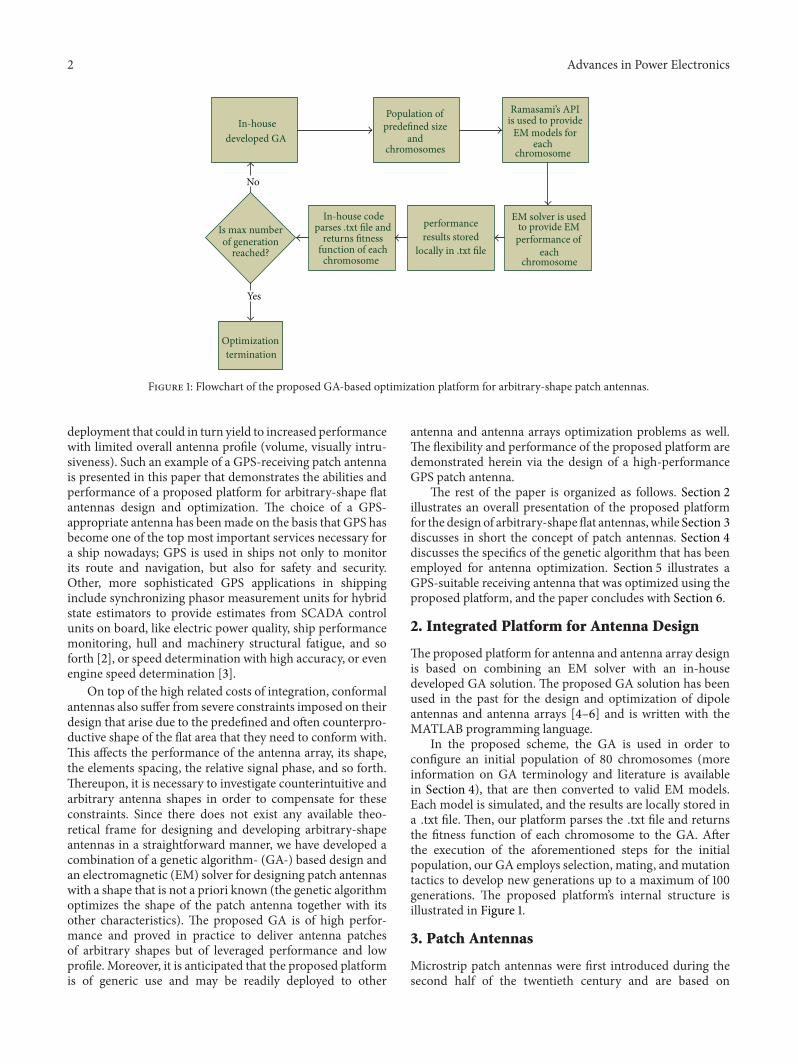
Figure 1: Flowchart of the proposed GA-based optimization platform for arbitrary-shape patch antennas.
deployment that could in turn yield to increased performancewith limited overall antenna profile (volume, visually intru-siveness). Such an example of a GPS-receiving patch antennais presented in this paper that demonstrates the abilities andperformance of a proposed platform for arbitrary-shape flatantennas design and optimization. The choice of a GPS-appropriate antenna has beenmade on the basis that GPS hasbecome one of the top most important services necessary fora ship nowadays; GPS is used in ships not only to monitorits route and navigation, but also for safety and security.Other, more sophisticated GPS applications in shippinginclude synchronizing phasor measurement units for hybridstate estimators to provide estimates from SCADA controlunits on board, like electric power quality, ship performancemonitoring, hull and machinery structural fatigue, and soforth [2], or speed determination with high accuracy, or evenengine speed determination [3].
On top of the high related costs of integration, conformalantennas also suffer from severe constraints imposed on theirdesign that arise due to the predefined and often counterpro-ductive shape of the flat area that they need to conform with.This affects the performance of the antenna array, its shape,the elements spacing, the relative signal phase, and so forth.Thereupon, it is necessary to investigate counterintuitive andarbitrary antenna shapes in order to compensate for theseconstraints. Since there does not exist any available theo-retical frame for designing and developing arbitrary-shapeantennas in a straightforward manner, we have developed acombination of a genetic algorithm- (GA-) based design andan electromagnetic (EM) solver for designing patch antennaswith a shape that is not a priori known (the genetic algorithmoptimizes the shape of the patch antenna together with itsother characteristics). The proposed GA is of high perfor-mance and proved in practice to deliver antenna patchesof arbitrary shapes but of leveraged performance and lowprofile. Moreover, it is anticipated that the proposed platformis of generic use and may be readily deployed to other
antenna and antenna arrays optimization problems as well.The flexibility and performance of the proposed platform aredemonstrated herein via the design of a high-performanceGPS patch antenna.
The rest of the paper is organized as follows. Section 2illustrates an overall presentation of the proposed platformfor the design of arbitrary-shape flat antennas, while Section 3discusses in short the concept of patch antennas. Section 4discusses the specifics of the genetic algorithm that has beenemployed for antenna optimization. Section 5 illustrates aGPS-suitable receiving antenna that was optimized using theproposed platform, and the paper concludes with Section 6.
2. Integrated Platform for Antenna Design
The proposed platform for antenna and antenna array designis based on combining an EM solver with an in-housedeveloped GA solution. The proposed GA solution has beenused in the past for the design and optimization of dipoleantennas and antenna arrays [4–6] and is written with theMATLAB programming language.
In the proposed scheme, the GA is used in order toconfigure an initial population of 80 chromosomes (moreinformation on GA terminology and literature is availablein Section 4), that are then converted to valid EM models.Each model is simulated, and the results are locally stored ina .txt file. Then, our platform parses the .txt file and returnsthe fitness function of each chromosome to the GA. Afterthe execution of the aforementioned steps for the initialpopulation, our GA employs selection, mating, andmutationtactics to develop new generations up to a maximum of 100generations. The proposed platform’s internal structure isillustrated in Figure 1.
3. Patch Antennas
Microstrip patch antennas were first introduced during thesecond half of the twentieth century and are based on
Advances in Power Electronics 3
Feeding line
Patch
Ground plane
𝑧 𝑦
𝑥
𝐿
𝑊
𝑊
ℎ
ℎ
𝑡
𝜀𝑟
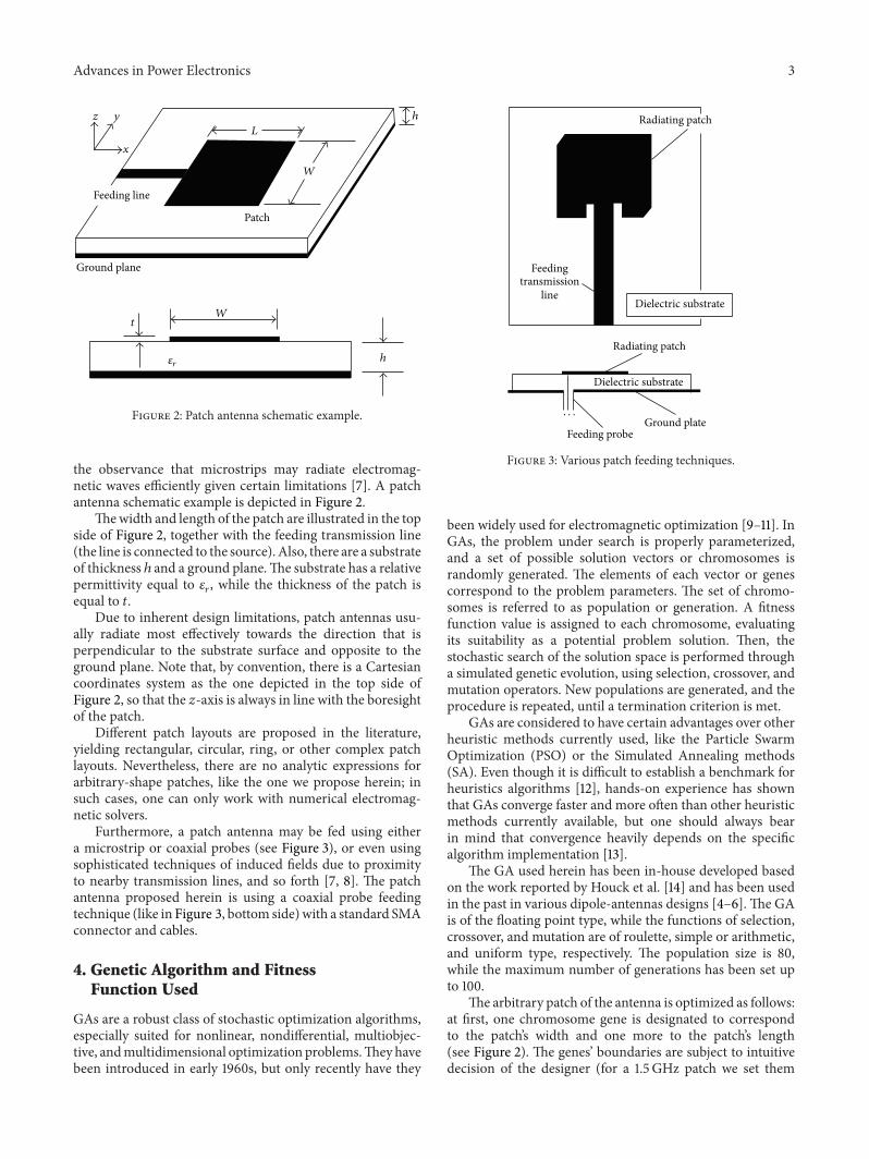
Figure 2: Patch antenna schematic example.
the observance that microstrips may radiate electromag-netic waves efficiently given certain limitations [7]. A patchantenna schematic example is depicted in Figure 2.
Thewidth and length of the patch are illustrated in the topside of Figure 2, together with the feeding transmission line(the line is connected to the source). Also, there are a substrateof thickness ℎ and a ground plane.The substrate has a relativepermittivity equal to 𝜀
𝑟, while the thickness of the patch is
equal to 𝑡.Due to inherent design limitations, patch antennas usu-
ally radiate most effectively towards the direction that isperpendicular to the substrate surface and opposite to theground plane. Note that, by convention, there is a Cartesiancoordinates system as the one depicted in the top side ofFigure 2, so that the 𝑧-axis is always in line with the boresightof the patch.
Different patch layouts are proposed in the literature,yielding rectangular, circular, ring, or other complex patchlayouts. Nevertheless, there are no analytic expressions forarbitrary-shape patches, like the one we propose herein; insuch cases, one can only work with numerical electromag-netic solvers.
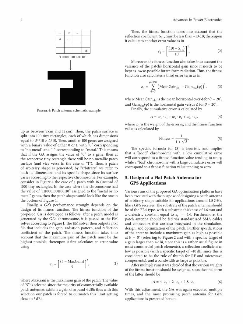
Furthermore, a patch antenna may be fed using eithera microstrip or coaxial probes (see Figure 3), or even usingsophisticated techniques of induced fields due to proximityto nearby transmission lines, and so forth [7, 8]. The patchantenna proposed herein is using a coaxial probe feedingtechnique (like in Figure 3, bottom side)with a standard SMAconnector and cables.
4. Genetic Algorithm and FitnessFunction Used
GAs are a robust class of stochastic optimization algorithms,especially suited for nonlinear, nondifferential, multiobjec-tive, andmultidimensional optimization problems.Theyhavebeen introduced in early 1960s, but only recently have they
Radiating patch
Radiating patch
Feedingtransmission
lineDielectric substrate
Dielectric substrate
Ground plateFeeding probe
· · ·
Figure 3: Various patch feeding techniques.
been widely used for electromagnetic optimization [9–11]. InGAs, the problem under search is properly parameterized,and a set of possible solution vectors or chromosomes israndomly generated. The elements of each vector or genescorrespond to the problem parameters. The set of chromo-somes is referred to as population or generation. A fitnessfunction value is assigned to each chromosome, evaluatingits suitability as a potential problem solution. Then, thestochastic search of the solution space is performed througha simulated genetic evolution, using selection, crossover, andmutation operators. New populations are generated, and theprocedure is repeated, until a termination criterion is met.
GAs are considered to have certain advantages over otherheuristic methods currently used, like the Particle SwarmOptimization (PSO) or the Simulated Annealing methods(SA). Even though it is difficult to establish a benchmark forheuristics algorithms [12], hands-on experience has shownthat GAs converge faster and more often than other heuristicmethods currently available, but one should always bearin mind that convergence heavily depends on the specificalgorithm implementation [13].
The GA used herein has been in-house developed basedon the work reported by Houck et al. [14] and has been usedin the past in various dipole-antennas designs [4–6]. The GAis of the floating point type, while the functions of selection,crossover, and mutation are of roulette, simple or arithmetic,and uniform type, respectively. The population size is 80,while the maximum number of generations has been set upto 100.
The arbitrary patch of the antenna is optimized as follows:at first, one chromosome gene is designated to correspondto the patch’s width and one more to the patch’s length(see Figure 2). The genes’ boundaries are subject to intuitivedecision of the designer (for a 1.5 GHz patch we set them
4 Advances in Power Electronics
1 2
4
16
“1110001001100110”
· · ·
· · ·
Figure 4: Patch antenna schematic example.
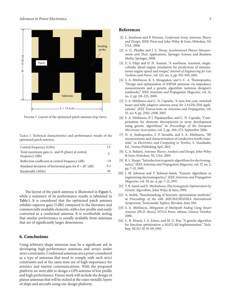
up as between 2 cm and 12 cm). Then, the patch surface issplit into 100 tiny rectangles, each of which has dimensionsequal to𝑊/10 × 𝐿/10. Then, another 100 genes are assignedwith a binary value of either 0 or 1, with “0” correspondingto “no metal” and “1” corresponding to “metal.” This meansthat if the GA assigns the value of “0” to a gene, then atthe respective tiny rectangle there will be no metallic patchsurface (and vice versa in the case of “1”). Thus, a patchof arbitrary shape is generated; by “arbitrary” we refer toboth its dimensions and its specific shape since its surfacevaries according to the respective chromosome. For example,consider in Figure 4 the case of a patch with 16 (instead of100) tiny rectangles. In the case where the chromosome hadthe value of “1110001001100110” assigned to the “metal or nometal” genes, then the patch shape would look like the one inthe bottom of Figure 4.
Finally, a GA’s performance strongly depends on thedesign of its fitness function. The fitness function of theproposed GA is developed as follows: after a patch model isgenerated by the GA’s chromosome, it is passed to the EMsolver according to Figure 1.The EM solver then outputs a.txtfile that includes the gain, radiation pattern, and reflectioncoefficient of the patch. The fitness function takes intoaccount that the maximum gain of the patch must be thehighest possible; thereupon it first calculates an error valueusing
𝑒1= [(5 −MaxGain)5
]
2
, (1)
where MaxGain is the maximum gain of the patch.The valueof “5” is selected since the majority of commercially availablepatch antennas exhibits a gain of around 4 dBi; thus with thisselection our patch is forced to outmatch this limit gettingclose to 5 dBi.
Then, the fitness function takes into account that thereflection coefficient, 𝑆
11, must be less than−10 dB; thereupon
it calculates another error value as in
𝑒2= [(10 − 𝑆
11)
10]
2
. (2)
Moreover, the fitness function also takes into account thevariance of the patch’s horizontal gain since it needs to bekept as low as possible for uniform radiation.Thus, the fitnessfunction also calculates a third error term as in
𝑒3=
𝜙=360∘
∑
𝜙=0∘
(MeanGainphi − Gainphi(𝜙))2
, (3)
whereMeanGainphi is themean horizontal over𝜙 for 𝜃 = 20∘,and Gainphi(𝜙) is the horizontal gain versus 𝜙 for 𝜃 = 20∘.
Finally, the cumulative error is calculated by
𝐴 = 𝑤1⋅ 𝑒1+ 𝑤2⋅ 𝑒2+ 𝑤3⋅ 𝑒3, (4)
where𝑤1is the weight of the error 𝑒
𝑖, and the fitness function
value is calculated by
Fitness = 11 + √𝐴. (5)
The specific formula for (5) is heuristic and impliesthat a “good” chromosome with a low cumulative errorwill correspond to a fitness function value tending to unity,while a “bad” chromosome with a large cumulative error willcorrespond to a fitness function value tending to zero.
5. Design of a Flat Patch Antenna forGPS Applications
Various runs of the proposed GA optimization platform havebeen executed with the purpose of designing a patch antennaof arbitrary shape suitable for applications around 1.5 GHz,like a GPS receiver.The substrate of the patch antenna shouldbe of the FR4 type, with a substrate thickness of 1.6mm anda dielectric constant equal to 𝜀
𝑟= 4.6. Furthermore, the
patch antenna should be fed via standardized SMA cablesand connectors that are also integrated in the simulation,design, and optimization of the patch. Further specificationsof the antenna include a maximum gain as high as possibleat 𝜃 = 0∘ (referring to Figure 2 and with a specific target ofa gain larger than 4 dBi, since this is a rather usual figure inmost commercial patch elements), a reflection coefficient aslow as possible (with a specific target of −10 dB, since this isconsidered to be the rule of thumb for RF and microwavecomponents), and a bandwidth as large as possible.
Aftermultiple runs it was decided that the variousweightsof the fitness function should be assigned, so as the final formof the latter should be
𝐴 = 4 ⋅ 𝑒1+ 2 ⋅ 𝑒
2+ 1.8 ⋅ 𝑒
3. (6)
With this adjustment, the GA was again executed multipletimes, and the most promising patch antenna for GPSapplications is presented herein.
Advances in Power Electronics 5
Patch
Substrate
Feedingprobe
𝑊=13.45
cm
𝐿 = 13.4 cm
Figure 5: Layout of the optimized patch antenna (top view).
Table 1: Technical characteristics and performance results of theoptimized patch antenna.
Central frequency (GHz) 1.5Total maximum gain (e- and H-plane) at centralfrequency (dBi) 5
Reflection coefficient at central frequency (dB) −14Standard deviation of horizontal gain for 𝜃 = 20∘ (dB) 0.3Bandwidth (MHz) 50
The layout of the patch antenna is illustrated in Figure 5,while a summary of its performance results is tabulated inTable 1. It is considered that the optimized patch antennaexhibits superior gain (5 dBi) compared to the literature andcommercially available elements, with a low profile and easilyconverted to a conformal antenna. It is worthwhile notingthat similar performance is usually available from antennasthat are of significantly larger dimensions.
6. Conclusions
Using arbitrary-shape antennas may be a significant aid indeveloping high-performance antennas and arrays understrict constraints. Conformal antennas are a priori consideredas a type of antennas that need to comply with such strictconstraints and at the same time are of high importance foravionics and marine communications. With the proposedplatform we were able to design a GPS antenna of low profileand high performance. Future work will include the design ofplanar antennas that will be etched at the outermetallic layersof ships and aircrafts using our design platform.
References
[1] L. Josefsson and P. Persson, Conformal Array Antenna Theoryand Design, IEEE Press and John Wiley & Sons, Hoboken, NJ,USA, 2006.
[2] A. G. Phadke and J. S. Thorp, Synchronized Phasor Measure-ments and Their Applications, Springer Science and BusinessMedia, Springer, 2008.
[3] Z. S. Filipi and D. N. Assanis, “A nonlinear, transient, single-cylinder diesel engine simulation for predictions of instanta-neous engine speed and torque,” Journal of Engineering for GasTurbines and Power, vol. 123, no. 4, pp. 951–959, 2001.
[4] S. A. Mitilineos, K. S. Mougiakos, and S. C. A. Thomopoulos,“Design and optimization of ESPAR antennas via impedancemeasurements and a genetic algorithm (antenna designer’snotebook),” IEEE Antennas and Propagation Magazine, vol. 51,no. 2, pp. 118–123, 2009.
[5] S. A. Mitilineos and C. N. Capsalis, “A new, low-cost, switchedbeam and fully adaptive antenna array for 2.4GHz ISM appli-cations,” IEEE Transactions on Antennas and Propagation, vol.55, no. 9, pp. 2502–2508, 2007.
[6] S. A. Mitilineos, P. I. Papakanellos, and C. N. Capsalis, “Com-pensation for elements discrepancies in array developmentusing genetic algorithms,” in Proceedings of the EuropeanMicrowave Association, vol. 2, pp. 269–273, September 2006.
[7] N. A. Stathopoulos, S. P. Savaidis, and S. A. Mitilineos, “RFmeasurements and characterization of conductive textile mate-rials,” in Electronics and Computing in Textiles, S. Vassiliadis,Ed., Ventus Publishing ApS, 2012.
[8] C. A. Balanis, AntennaTheory: Analysis and Design, JohnWiley& Sons, Hoboken, NJ, USA, 2005.
[9] R. L.Haupt, “Introduction to genetic algorithms for electromag-netics,” IEEE Antennas and PropagationMagazine, vol. 37, no. 2,pp. 7–15, 1995.
[10] J. M. Johnson and Y. Rahmat-Samii, “Genetic algorithms inengineering electromagnetics,” IEEE Antennas and PropagationMagazine, vol. 39, no. 4, pp. 7–21, 1997.
[11] Y. R. Samii and E.Michielssen, Electromagnetic Optimization byGenetic Algorithms, John Wiley & Sons, 1999.
[12] A. Stefek, “Benchmarking of heuristic optimization methods,”in Proceedings of the 14th MECHATRONIKA InternationalSymposium, Trencianske Teplice, Slovakia, June 2011.
[13] S. A. Mitilineos, Mitigation of Multipath Fading Using SmartAntenas [Ph.D. thesis], NTUA Press, Athens, Greece, October2006.
[14] C. R. Houck, J. A. Joines, and M. G. Kay, “A genetic algorithmfor function optimization: a MATLAB implementation,” Tech.Rep. NCSU-IE 95-09, 1995.

International Journal of
AerospaceEngineeringHindawi Publishing Corporationhttp://www.hindawi.com Volume 2014
RoboticsJournal of
Hindawi Publishing Corporationhttp://www.hindawi.com Volume 2014
Hindawi Publishing Corporationhttp://www.hindawi.com Volume 2014
Active and Passive Electronic Components
Control Scienceand Engineering
Journal of
Hindawi Publishing Corporationhttp://www.hindawi.com Volume 2014
International Journal of
RotatingMachinery
Hindawi Publishing Corporationhttp://www.hindawi.com Volume 2014
Hindawi Publishing Corporation http://www.hindawi.com
Journal ofEngineeringVolume 2014
Submit your manuscripts athttp://www.hindawi.com
VLSI Design
Hindawi Publishing Corporationhttp://www.hindawi.com Volume 2014
Hindawi Publishing Corporationhttp://www.hindawi.com Volume 2014
Shock and Vibration
Hindawi Publishing Corporationhttp://www.hindawi.com Volume 2014
Civil EngineeringAdvances in
Acoustics and VibrationAdvances in
Hindawi Publishing Corporationhttp://www.hindawi.com Volume 2014
Hindawi Publishing Corporationhttp://www.hindawi.com Volume 2014
Electrical and Computer Engineering
Journal of
Advances inOptoElectronics
Hindawi Publishing Corporation http://www.hindawi.com
Volume 2014
The Scientific World JournalHindawi Publishing Corporation http://www.hindawi.com Volume 2014
SensorsJournal of
Hindawi Publishing Corporationhttp://www.hindawi.com Volume 2014
Modelling & Simulation in EngineeringHindawi Publishing Corporation http://www.hindawi.com Volume 2014
Hindawi Publishing Corporationhttp://www.hindawi.com Volume 2014
Chemical EngineeringInternational Journal of Antennas and
Propagation
International Journal of
Hindawi Publishing Corporationhttp://www.hindawi.com Volume 2014
Hindawi Publishing Corporationhttp://www.hindawi.com Volume 2014
Navigation and Observation
International Journal of
Hindawi Publishing Corporationhttp://www.hindawi.com Volume 2014
DistributedSensor Networks
International Journal of