research article dynamic analysis of cable-stayed bridges...
TRANSCRIPT
Hindawi Publishing CorporationMathematical Problems in EngineeringVolume 2013 Article ID 302706 20 pageshttpdxdoiorg1011552013302706
Research ArticleDynamic Analysis of Cable-Stayed Bridges Affected byAccidental Failure Mechanisms under Moving Loads
Fabrizio Greco Paolo Lonetti and Arturo Pascuzzo
Department of Structural Engineering University of Calabria P Bucci Road Cubo39-B Rende 87030 Cosenza Italy
Correspondence should be addressed to Paolo Lonetti lonettiunicalit
Received 21 August 2012 Accepted 14 November 2012
Academic Editor Xiaojun Wang
Copyright copy 2013 Fabrizio Greco et al This is an open access article distributed under the Creative Commons Attribution Licensewhich permits unrestricted use distribution and reproduction in any medium provided the original work is properly cited
Thedynamic behavior of cable-stayed bridges subjected tomoving loads and affected by an accidental failure in the cable suspensionsystem is investigatedThemain aim of the paper is to quantify numerically the dynamic amplification factors of typical kinematicand stress design variables by means of a parametric study developed in terms of the structural characteristics of the bridgecomponents The bridge formulation is developed by using a geometric nonlinear formulation in which the effects of localvibrations of the stays and of large displacements in the girder and the pylons are taken into account Explicit time dependentdamage laws reproducing the failure mechanism in the cable system are considered to investigate the influence of the failure modecharacteristics on the dynamic bridge behavior The analysis focuses attention on the influence of the inertial characteristics of themoving loads by accounting coupling effects arising from the interaction between girder and moving system Sensitivity analysesof typical design bridge variables are proposed In particular the effects produced by the moving system characteristics the towertypologies and the failure mode characteristics involved in the cable system are investigated by means of comparisons betweendamaged and undamaged bridge configurations
1 Introduction
Cable supported bridges are frequently employed in thecontext of long spans leading to slender structures inwhich typically the dead loads are comparable with thoseinvolved in the live load configuration As a consequence theexternal loads are able to produce high amplifications of themain bridge kinematic and stress design parameters leadingto nonstandard excitation modes and unexpected damagemechanisms in the structural components of the bridge Inorder to simulate the actual behavior of the bridge the struc-turalmodeling should be able to reproduce the source of non-linearities in the cable system in the girder or in the pylonsdue to cable sag or beam-column large deformation effectsrespectively Moreover additional complexities arise in theprediction of the bridge behavior in the presence of damagemechanisms which strongly reduce the structural integrity ofthe bridge As amatter of fact cable-supported structures aretypically affected by degradation effects such as corrosionabrasion and fatigue which may cause a reduction of thestiffness properties or in extreme cases the complete failure
of a single or multiple cable elements In the literature manyinvestigations have been developed to analyze the influenceof the moving loads on the dynamic behavior of cable-supported bridges mainly for undamaged bridge structuresActually many models are devoted to predicting dynamicbridge behavior by using refined structural schematizationsas well as accurate descriptions of the moving loads [1ndash4] Inthis framework the bridge behavior is analyzed by means ofanalytical continuum approaches or finite element models inwhich the behavior of the cable suspension system is typicallydescribed by means of linear equations expressed in termsof tangent or secant Dischinger elastic moduli [5ndash8] Thisassumption is frequently supported by experimental evidencefor static analyses [9 10] However in order to reproducethe dynamic behavior correctly especially when the bridgeis subjected to extreme loading conditions local vibrationeffects of the cable elements should be properly taken intoaccount [2 11] Additional complexities in the prediction ofthe dynamic behavior of long span bridges arise from thedescription of the interaction behavior betweenmoving loadsand bridge vibrations At this aim many papers have been
2 Mathematical Problems in Engineering
developed to analyze the influence of the external mass andits motion on the bridge behavior introducing an accuratedescription of the inertial forces between bridge deformationand moving load kinematic [7 8 12] However a brief litera-ture review denotes that the behavior of cable-stayed bridgesis mainly analyzed for undamaged structures whereas theinfluence of cable failure mechanisms produced by loss ofstiffness due to cable degradation or due to an accidentalfailure is rarely analyzed Typically many papers are devotedto investigating the effects on the dynamic behavior of asingle cable element of a localized or a distributed timeindependent damage mechanisms [13] without entering indetail on time dependence characteristics of the failure modeor the coupling behavior between damaged and undamagedelements of the cable system The results proposed in thisframework show how damage phenomena induce tensionloss and sag augmentation of the static undamaged cableprofile
Since cable elements are mostly utilized in supportedbridges studies developed on single cables have been gener-alized to evaluating the influence of damage phenomena onrealistic cable structures In particular damage behavior ofcable-stayed beam has been analyzed by means of numericalapproaches in which the effects of diffused inelastic damageconcerning the intensity and location characteristics havebeen investigated [14] Such results show how the damageeffects produce relevant modifications with respect to theundamaged configuration of the natural frequencies andmode shapes of the structureMoreover further investigationhas been developed in the framework of cable-stayed bridge
It is worth noting that fromadesign point of view existingcodes on cable-stayed bridges that is PTI [15] and SETRA[16] in order to identify the amplification effects providedby the failure mechanism in the cable system recommend toamplify the results obtained in the framework of quasistaticanalyses by using fictitious amplification factors suggested inthe range between 15 and 20 In particular the codes identifythe dynamic characteristics of the failure mode of a genericelement of the cable system introducing a static loadingconfiguration in which the cable failure is reproduced bymeans of compression forces to simulate cable release Thestress distribution arising from such a loading scheme iscombined with the effects of other existing loading schemesby means of proper factored loading combinations Howeverrecent papers have demonstrated that such a simplifiedapproach becomes unsafe in many cases leading to dynamicamplification factors higher than those suggested by existingrecommendations [17ndash19] In particular some parametricstudies have been developed for bridge typologies subjectedto accidental cable failure by using a numerical approachbased on classical standard linear dynamic framework [1819] Such analyses denote that the results obtained by usingsuch code prescriptions are affected by high underestimationsin the prediction of typical design bridge variables relatedto the girder and pylons However in order to correctlyreproduce the bridge behavior additional developments arerequired to be simulate the effect produced by the nonlin-earities and damage mechanisms involved cable system andby the inertial coupling between girder and moving loads
deformations Actually comprehensive analyses that includesuchnon linear dynamic effects are quite rare and thus furtherinvestigations to verify code prescriptions and to quantify theinfluence on the bridge behavior of the dynamic excitationproduced by the failure mode characteristics of the cablesystem are much required
In the present paper the dynamic behavior of cable-stayed bridges subjected to cable failure mechanisms isinvestigated The numerical study consists on a tridimen-sional finite element model in which both A-shaped andH-shaped pylons are investigated The aim of the paper isto propose a parametric study to investigate the influenceon the bridge behavior of the dynamic excitation producedby damage mechanisms in the cable system and the transitof moving loads Differently from existing papers availablein the literature the proposed modeling reproduces theinertial description of the moving loads by means of arefined schematization of the inertial forces produced bythe moving system and girder bridge interaction Moreoverlocal vibrations of the cable elements are taken into accountby reproducing the nonlinearities involved in the cable-sageffect in the cable system as well as large deformations inthe girder and the pylons Finally the stay failure mecha-nism is formulated consistently with a Continuous DamageMechanics approach introducing time dependent damagefunctions which control the constitutive behavior of thefailure mechanism and thus the inertial characteristics of theloss of cable stiffness The outline of the paper is as followsSection 2 presents the general formulation of the cable andthe girder elements the damage description of the cablemodel and the evaluation of the initial configuration thenumerical implementation is reported in Section 3 paramet-ric studies in terms of bridge andmoving loads characteristicsand failure mode typology in the cable system are reported inSection 4
2 Bridge Formulation
In this section the governing equations for the bridgeconstituents as well as the main assumptions concerningthe kinematic modeling are discussed In particular themain assumptions concerning the kinematic modeling ofthe bridge the damage formulation adopted to simulatecable failure and the inertial forces to define the movingloadsgirder interaction are discussed Such governing equa-tions represent the basis for the theoretical formulation ofthe model whose numerical implementation is presented inSection 3
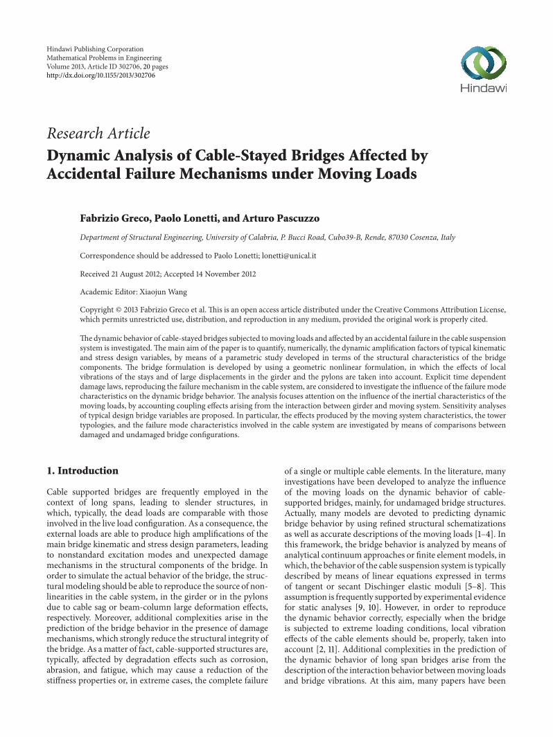
21 Cable System Formulation and Initial Configuration underDead Loading The bridge scheme is based on a tridimen-sional modeling in which both in plane and out of planedeformation modes are considered The structural modelreported in Figure 1 is consistent with a fan-shaped anda self-anchored cable-stayed bridge scheme Moreover thepylons analyzed by the present paper refer to A- or H-shaped typologies Every single cable of the suspensionsystem is simulated by using a sequence of the 119899 truss
Mathematical Problems in Engineering 3
l L l
L
b
ct
sc
X
X
KP
H
A
U1(t)
s
(2l+Lt)
KPA0
P
X
X
b
eH
U1
3
2
1
3
1
P
b b
e
c A0c
c Ac
G
EGAG EGIG2 EGIG2 J
Gt
UG2 (X1 t)
UG1 (X1 t)
minusUG3 (X1 t)
minusUG3 (X1 t)
minusUC3 (st)
ΦG1 (X1 t)
UG1 (minus1 + 12 t)
Sc1A
c
Sc1A
c
α0α0
∆
α(X1)
Cc Sc1
LS(x)
Figure 1 Cable-stayed bridge scheme bridge kinematic pylons girder and cable system characteristics
l L2
ULP
S1C
S2CS3C S4
C
Sn2C
UjG
Uj+1G
UG
H
g
Sj+1C
SjC
Figure 2 Cable-stayed configuration under dead loading internal stresses and kinematic parameters
elements which are connected at the cross-section ends ofthe girder profile and at the top cross-section of the towerThe formulation is consistent with a large deformation theorybased on the Green-Lagrange strain measure and the secondPiola-Kirchhoff stress [20] whereas the material behavior isassumed to be linearly elastic Since the cable behavior ismostly influenced by the preexisting stress and strain statusthe initial configuration under the dead loading must beidentified in advance In particular with respect to the finalstep of a balanced cantilever construction method in whichonly the central segment of the deck is left the geometricshape design of the bridge and the corresponding internalstresses of the cable system are obtained enforcing the deckand the top pylon cross-section kinematic variables to remainin the undeformed configuration that is ldquozero configurationrdquo[10] In order to calculate the initial stress distribution inthe cable system an optimization solving problem should bedeveloped In particular with reference to the cable-stayed
bridge scheme reported in Figure 2 with 119899 number of staysthe objective functions are represented by the displacementvector
˜119880 containing the 119899 minus 2 vertical displacements that
is (1198801198662 119880
119866
119899minus3 119880
119866
119899minus2) excluding those points associated
with the anchor stays at the cablegirder connections andthe horizontal displacements of the top cross-section of thepylons (119880119875
119871 119880
119875
119877)
˜119880119879= [119880
119875
119871 119880
119875
119877 119880
119866
2 119880
119866
119899minus3 119880
119866
119899minus2] (1)
Moreover the design variables which have to be calcu-lated correspond to the internal stress distribution of thecable system that is
˜119878119879= [119878
119862
1 119878119862
2 119878
119862
119899119888minus1 119878119862
119899] Since
the relationships between displacements and cable stressesare essentially nonlinear a specialized solving procedure tocalculate the initial configuration is required In particularstarting from an initial trial distribution in the cable systemthat is
˜1198780 the vertical displacements under the dead loading
4 Mathematical Problems in Engineering
can be expressed to the first order by the Taylor expansion interms of the incremental cable stress distribution by meansof the following linearized equations
˜119880(
˜1198780+ Δ
˜119878 119901) =
˜119880 (
˜1198780 119901) +
119889
˜119880
119889
˜119878
10038161003816100381610038161003816100381610038161003816(
˜1198780119901)
sdot Δ
˜119878 + 119900
10038171003817100381710038171003817Δ
˜119878210038171003817100381710038171003817
(2)
where˜119880(
˜1198780 119901) is a vector containing the displacements
in the self weight loading condition and subjected to thestress distribution
˜1198780 119901 is the loading parameter associated
to the application of the dead loading and (119889˜119880119889
˜119878)|
(
˜1198780119901)
is the directional derivative of˜119880 at
˜1198780coinciding with
the flexibility matrix of the structure In (2) the unknownquantity is represented by the incremental vector related tothe cable stress distribution namelyΔ
˜119878 which is determined
enforcing the displacement vector˜119880(
˜119878 + Δ
˜119878 119901) to be zero
under the action of the dead loading Since the structureis affected by a nonlinear behavior an iterative procedurebased on the Newton-Raphson scheme is adopted Moredetails regarding the solving procedure to calculate the zeroconfiguration are reported in Section 3 which is essentiallydevoted to analyzing the numerical implementation of theproposed modeling
With reference to the structural bridge scheme reportedin Figure 1 it is assumed that the cable system is composed ofundamaged elements and a fixed number of elements whichare affected during the moving loads by an internal cablefailure mechanism In particular the damage formulation isdeveloped by means of explicit time dependence laws whichreproduce the phenomenon of the cable release in a shorttime step due to an accidental failure in the cable systemsuch as the one occurring during a terroristic or vandalismattack and thus is not related to creep damage On thecontrary the remaining stays are assumed to be undamagedand thus the damage function is set to zero The stay failureof the 119894th generic stay is simulated by introducing a damageevolution law in the constitutive relationships In particulara time dependent damage function is utilized which reducesduring the assumed failure time step the elastic materialproperties of the cable as well as the corresponding initialinternal stresses Among the several approaches availablefrom the literature the formulation is assumed to be consis-tent with the ContinuumDamageMechanicsTheory [21 22]In this context degradation functions physically based areintroduced to reproduce a typical damage phenomenon ofthe cable system The definition of the damage function isdeveloped introducing a scalar variable 119863 representative ofthe failure mechanism defined by means of the followingscalar expression
119863(119904 119905) =
119896 (119904 119905) minus 119896119889 (119904 119905)
119896 (119904 119905)
with 119863 isin [0 1] (3)
where 119904 is the curvilinear coordinate used to describe the arclength of the cable 119896 and 119896
119889are the actual and residual stiff-
ness properties for example area or modulus of the cablerespectively In order to reproduce the failure mechanismof the generic cable element a time dependent damage law
G
P
Linear configurationStatic profile
1X
3X
2X
ij
ij
Dynamic configuration
UG2
UP1
UP2
UP3
UG1
UG3
Figure 3 Initial and current configurations of the cable supportmotion due to girder (119866) and pylon (119875) deformation
based on Kachanov or Rabotnov type approach [21 22] isintroduced The damage function is expressed through anexplicit evolution law in the failure time domain definedby the initial (1199050) and the final (119905119891) times of the failuremechanism and the critical value of the damage variable 119863119888by means of the following expression
119863(119904 119905) = 1 minus (1 minus
119905119891minus (119905 minus 119905
0)
119905119891
)
1(1+119898)
(4)
with
119905119891 =
1 minus (1 minus 119863119888)119898+1
119898 + 1
(
119878
1198600
)
minus119898
(5)
where 119898 and 1198600are material damage parameters More
details about the mathematical relationships leading to (4)-(5) can be found in the appendix It is worth noting thatthe critical damage parameter represents the value corre-sponding to the occurrence of the complete failure of thecable element in which the 119894th generic stay does not havethe possibility of transferring any internal stresses fromthe girder and the tower and thus can be considered notto produce any significant effects on the global behaviorof the bridge Moreover the above formulation cannot beconsidered in the creep damage framework since the cablerelease phenomenon is produced in a short time step and it isconcerned to simulate essentially an accidental failure in thecable system
The formulation is presented assuming that the cableelement is deformed in its initial cable configuration underdead loading that isΩ
119888 and thus the deformed configuration
of the cable due to the application of the live loads can bedescribed by the following additive expression (Figure 3)
˜120593 (
˜119883 119905) = (1198831
+ 119880119862
1(
˜119883 119905))
˜1198991+ (119883
2+ 119880
119862
2(
˜119883 119905))
˜1198992
+ (1198833 + 119880119862
3(
˜119883 119905))
˜1198993
(6)
where˜119883 with
˜119883119879= [119883
1 119883
2 119883
3] is the positional vector of
the cable cross-sections119880119862119894with 119894 = 1 3 are the displacement
components in the local reference axis 119883119894described by the
basis 119899119894of the coordinate system The main equations for
Mathematical Problems in Engineering 5
X
2c
R(s) R(s+ds)
ds
s
X3
X1
e
X
ΦG1
ΦG2
ΦG3
UG2
UG1
UG3
RX3X2
UmX3
RX3
RX3
λ λ0
λ λ0
(a) (b)
j
i
Figure 4 Girder kinematic (a) and moving loads description (b)
the generic 119894th stay are described by introducing the damageevolution law defined by (4) in the constitutive law definedin terms of the Green-Lagrange strain and the second Piola-Kirchhoff stress as
119878119862
1(
˜119883 119905) = 119862
119862[1 minus 120575
119894119896119863 (119905)] 119864
119862
1(
˜119883 119905) + 119878
119862
0
119864119862
1(
˜119883 119905) = 119880
119862
11198831
(
˜119883 119905)
+
1
2
[1198802
11198831
(
˜119883 119905) + 119880
2
21198831
(
˜119883 119905) + 119880
2
31198831
(
˜119883 119905)]
119862
(7)
where 119862119862 is the elastic modulus 120575119894119896 is the Kronecker deltafunction 119878119862
1is the second Piola-Kirchhoff axial stress 119864119862
1is
the Green-Lagrange axial strain and 1198781198620is the second Piola-
Kirchhoff axial stress in the zero configurationThegoverningequations of the motion of a single cable are expressed bymeans of the following partial differential equations [23]
119889
1198891198831
[119873119862
1+ 119873
119862
1
119889119880119862
1
1198891198831
] minus 1198871 minus 120583119888119862
1= 0
119889
1198891198831
[119873119862
1
119889119880119862
2
1198891198831
] minus 120583119888119862
2= 0
119889
1198891198831
[119873119862
1
119889119880119862
3
1198891198831
] minus 1198872minus 120583
119888119862
3= 0
with 1198871 = 120583119866119892 cos (1205931)
1198872= 120583
119866119892 sin (120593
2)
(8)
where 1198731198621is the axial force defined as 119873119862
1= 119878
119862
1119860119862 with
119860119862 the area of generic 119894th cable element 120593
1and 120593
2are
the slope angles of the cable along the 11988311198832and 119883
11198833
respectively and 1198871and 119887
2are the body load projections
in the 11988311198832and 119883
11198833 respectively In addition to (8)
boundary conditions on the cable kinematic are needed to
describe the support motion produced by the girder andpylon motion at the corresponding intersection points withthe cable development
˜119880119862(
˜1198830) =
˜119880119875
˜119880
119862
(
˜1198830) =
˜119880
119875
˜119880119862(
˜119883119888) =
˜119880119866
˜119880
119862
(
˜1198830) =
˜119880
119866
(9)
where˜1198830and
˜119883119888correspond to the initial and final cross-
sections of the cable element (˜119880119875
˜119880
119875
) and (˜119880119866
˜119880
119866
) are thedisplacement and speed of the pylon (119875) and girder (119866)respectively at the corresponding intersections with the cabledevelopment
22 Girder and Moving Loads Interaction Girder and towersare described by tridimensional geometric nonlinear beamelements bymeans of a formulation based on Euler-Bernoullikinematic assumptions and a Green-Lagrange strain mea-sureThe girder is connected with the cable system at the endpoints of the cable cross-sections and at the bottom cross-section ends of the towers consistently defined with ldquoH-rdquoor ldquoA-rdquo shaped typologies With reference to Figure 4(a) thedisplacements of the cross-section for a generic point locatedat the (1198831 1198832 1198833) coordinate that is (119880
119866
1 119880
119866
2 119880
119866
3) are
expressed by the following relationships
119880
119866
1(119883
1 119883
2 119883
3 119905) = 119880
119866
1(119883
1 119905) + Φ
119866
2(119883
1 119905) 119883
3
minus Φ119866
3(119883
1 119905) 119883
2
119880
119866
2(119883
1 119905) = 119880
119866
2(119883
1 119905)
119880
119866
3(119883
1 119883
2 119883
3 119905) = 119880
119866
3(119883
1 119905) + Φ
119866
1(119883
1 119905) 119883
2
(10)
where (1198801198661 119880
119866
2 119880
119866
3) and (Φ119866
1 Φ
119866
2 Φ
119866
3) are the displacement
and rotation fields of the centroid axis of the girder withrespect to the global reference system respectively
The external loads are assumed to proceed with constantspeed c from left to right along the bridge development and
6 Mathematical Problems in Engineering
are supposed to be located eccentrically with respect to thegeometric axis of the girder The moving system descrip-tion refers to railway vehicle loads which are reproducedby means equivalent uniformly distributed loads perfectlyconnected to the girder profile As a result the kinematicparameters of the moving system coincide with the onesdefined by the girder neglecting frictional forces arising fromthe external loads roughness effects of the girder profileand local loading distribution produced by railway loadcomponents However these assumptions are quite recurrentin the framework of cable supported bridges with longspans in which typically such interaction forces producedby localized dynamic effects are negligible with respect tothe global bridge vibration [24] Moreover it is assumed thatthe damping energy is practically negligible This hypothesisis verified in the context of long span bridges where it hasbeen proved that the bridge damping effects tend to decreaseas span length increases [25 26] Detailed results about theinfluence of damping effects on DAFs have been presentedin [5 6] from which it transpires that the assumption ofan undamped bridge system leads to greater DAFs Withreference to the structural scheme reported in Figure 4(b)the infinitesimal reaction forces produced by themoving loadon the girder profile can be expressed as a function of timedependent positional variable 119904 with 119904(119905) = 119888119905 by means ofthe balance of linear momentum as follows
1198891198771198833
= 1198891198831
120582119892+
119889
119889119905
[
[
120582
119889119880
119898
3
119889119905
(119904 (119905))]
]
100381610038161003816100381610038161003816100381610038161003816100381610038161003816119904=1198831
= 1198891198831
120582119892+
119889120582
119889119905
119889119880
119898
3
119889119905
(119904 (119905))+120582
1198892 119880
119898
3
1198891199052(119904 (119905))
100381610038161003816100381610038161003816100381610038161003816100381610038161003816119904=1198831
1198891198771198832
= 1198891198831
119889
119889119905
[
[
120582
119889119880
119898
2
119889119905
(119904 (119905))]
]
100381610038161003816100381610038161003816100381610038161003816100381610038161003816119904=1198831
= 1198891198831
119889120582
119889119905
119889119880
119898
2
119889119905
(119904 (119905)) + 120582
1198892 119880
119898
2
1198891199052(119904 (119905))
100381610038161003816100381610038161003816100381610038161003816100381610038161003816119904=1198831
1198891198771198831
= 1198891198831
119889
119889119905
[
[
120582
119889119880
119898
1
119889119905
(119904 (119905))]
]
100381610038161003816100381610038161003816100381610038161003816100381610038161003816119904=1198831
= 1198891198831
119889120582
119889119905
119889119880
119898
1
119889119905
(119904 (119905)) + 120582
1198892 119880
119898
1
1198891199052(119904 (119905))
100381610038161003816100381610038161003816100381610038161003816100381610038161003816119904=1198831
(11)
where 119892 is the gravitational acceleration 120582 is the externalmass per unit length and 119880119898
119894with 119894 = 1 3 are the displace-
ment functions along 119883119894axis of the moving mass identified
by the girder kinematic by using (10) as 119880119898119894= 119880
119894 It
is worth noting that in (11)1 at right hand side the firstterm represents the dead loading contribution whereas thesecond term is produced by the unsteady mass distribution
in the system due to time dependence character of the massfunction arising from the moving loads Finally the thirdterm must be calculated taking into account the relativemotion between bridge and the moving mass as follows [27]
119889119880
119898
119894
119889119905
=
120597119880
119898
119894
120597119905
+
120597119880
119898
119894
120597119904
120597119904
120597119905
=
120597119880
119898
119894
120597119905
+
120597119880
119898
119894
120597119904
119888
(12)
1198892119880
119898
119894
1198891199052=
119889
119889119905
[
120597119880
119898
119894
120597119905
+
120597119880
119898
119894
120597119905
120597119904 (119905)
120597119905
]
=
1205972119880
119898
119894
1205971199052+ 2119888
1205972119880
119898
119894
120597119905120597119904
+ 11988821205972119880
119898
119894
1205971199042
(13)
It is worth noting that the Eulerian description of themoving system introduces in (13) three terms correspondingto standard centripetal and Coriolis acceleration functionsrespectively However the last two contributions in theacceleration function for the transverse and longitudinaldisplacements that is when 119894 = 1 2 are typically negligiblein comparison to the term associated with the standardacceleration and thus they are not considered in the followingcomputations Substituting (10) into (11) with 119880119898
119894= 119880119894
and making the use of (12)-(13) the reaction forces per unitlength produced by the moving system are described by thefollowing expressions
1199011198833
=
1198891198771198833
1198891198831
= 120582119892 +
119889120582
119889119905
[(
120597119880119866
3
120597119905
+ 119890
120597Φ119866
1
120597119905
) + 119888(
120597119880119866
3
1205971198831
+ 119890
120597Φ119866
1
1205971198831
)]
+ 120582[
1205972119880119866
3
1205971199052+ 2119888
1205972119880119866
3
1205971199051205971198831
+ 119888
1205972119880119866
3
1205971198831
2]
+ 120582 sdot 119890 [
1205972Φ119866
1
1205971199052+ 2119888
1205972Φ119866
1
1205971199051205971198831
+ 119888
1205972Φ119866
1
1205971198831
2]
1199011198832
=
1198891198771198832
1198891198831
=
119889120582
119889119905
120597119880119866
2
120597119905
+ 120582
1205972119880119866
2
1205971199052
1199011198831
=
1198891198771198831
1198891198831
=
119889120582
119889119905
[(
120597119880119866
1
120597119905
minus 119890
120597Φ119866
3
120597119905
)] + 120582
1205972119880119866
1
1205971199052minus 120582 sdot 119890
1205972Φ119866
3
1205971199052
=
119889120582
119889119905
[(
120597119880119866
1
120597119905
minus 119890
1205972119880119866
2
1205971199051205971198831
)] + 120582
1205972119880119866
1
1205971199052minus 120582 sdot 119890
1205973119880119866
3
1205971199052120597119883
1
(14)
where 119890 is the eccentricity of the moving loads with respectto the girder geometric axis Moreover in (14) the massfunction during the external load advance can be expressed
Mathematical Problems in Engineering 7
with respect to the global reference system assumed from theleft end of the bridge as
120582 (1199041 119905) = 120582ML119867(1199041 + 119871119901 minus 119888119905)119867 (119888119905 minus 1199041) (15)
where 119867(sdot) is the Heaviside step function 119871119901 is the lengthof the moving loads 1199041 is the referential coordinate locatedat the left end of the girder cross-section that is 1199041 = 119897 +1198712 + 119883
1 and 120582
119872is the mass linear density of the moving
systemThe kinematic model is consistent with the geomet-
ric nonlinear Euler-Bernoulli theory in which moderatelylarge rotations are considered [26] The torsional behaviorowing to eccentric loading is described by means of theclassical De Saint Venant theory In particular the strainsare based on the Green-Lagrange measure in which onlythe square of the terms 1198802119866
1198941198831
representing the rotationsof the transverse normal line in the beam is consid-ered Therefore starting from (10) the following relation-ships between generalized strain and stress variables areobtained
119873119866
1= 119873
0(119866)
1+ 119864119860
119866120576119866
1
= 1198730(119866)
1+ 119864
119866119860119866119880
119866
11198831
+
1
2
[1198802119866
11198831
+ 1198802119866
21198831
+ 1198802119866
31198831
]
119872119866
2= 119872
0(119866)
2+ 119864119868
119866
2120594119866
2
= 1198720(119866)
2+ 119864
119866119868119866
2Φ119866
21198831
= 1198720(119866)
2minus 119864119868
119866
2119880119866
311988311198831
119872119866
3= 119872
0(119866)
3+ 119864119868
119866
3120594119866
3
= 1198720(119866)
3+ 119864
119866119868119866
3Φ119866
31198831
= 1198720(119866)
3+ 119864119868
119866
3119880119866
211988311198831
119872119866
1= 119866119869
119866
119905Θ119866= 119866
119866119869119866
119905Φ119866
11198831
(16)
where 119864119860119866 and 1205761198661are the axial stiffness and strain 120594119866
2and
120594119866
3or 119864119866119868119866
2and 119864119866119868119866
3are the curvatures or the bending
stiffnesses with respect to the 1198832 and 1198833 axes respectivelyΘ119866 and 119866119866119869119866
119905are the torsional curvature and stiffness
respectively1198731198661is the axial stress resultant119872119866
2and119872119866
3are
the bending moments with respect to the 1198832and 119883
3axes
respectively119872119866
1and 119866119866119869119866
119905are torsional moment and girder
stiffness respectively and (sdot)0 represents the superscript con-cerning the variables associatedwith the ldquozero configurationrdquoOn the basis of (16) taking into account of (14)-(15) andnotation reported in Figure 4(a) the following governing
equations are derived by means of the local form of dynamicequilibrium equations
119889
1198891198831
119873119866
1(1 +
119889119880119866
1
1198891198831
) minus 120583119866119866
1+ 119901
1198831
= 0
minus 119864119866119868119866
2
1198894119880119866
3
1198891198834
1
minus
119889
1198891198831
(119873119866
1
119889119880119866
3
1198891198831
)
minus 120583119866119866
3minus Φ
119866
21198831119868119866
02minus 119901
1198833
= 0
119864119866119868119866
3
1198894119880119866
2
1198891198834
1
minus
119889
1198891198831
(119873119866
1
119889119880119866
2
1198891198831
)
minus 120583119866119866
2minus Φ
119866
31198831119868119866
03+ 119901
1198832
= 0
119866119866119869119866
119905
1198892Φ119866
1
1198891198832
1
minus (119868119866
01+ 120582
0
ML) Φ119866
1minus 119901119883
3
119890 = 0
(17)
where 1205820ML is the per unit length torsional girder mass 120583119866
is the girder mass per unit length Additional equationsare required to take into account interelement continuityand initial conditions concerned with solving the dynamicproblem which can be expressed with reference to the 119894thgirder element as follows
119880119866
119896(0) = 0
119866
119896(0) = 0
119880119894(119866)
119896(0) = 119880
119894minus1(119866)
119896(119897119894minus1
119890) 119880
119866
119896(119897119894
119890) = 119880
119894+1
119896(0)
Φ119866
119896(0) = 0 Φ
119866
119896(0) = 0
Φ119894(119866)
119896(0) = Φ
119894minus1(119866)
119896(119897119894minus1
119890) Φ
119866
119896(119897119894
119890) = Φ
119894+1
119896(0)
(18)
where the superscripts 119894 + 1 and 119894 minus 1 indicate the previous orthe next girder elements and the subscript 119896 with 119896 = 1 2 3defines the displacement and rotation directions with respectto the coordinate reference system
3 Finite Element Implementation
The governing equations reported in the previous sectionintroduce a nonlinear partial differential system whoseanalytical solution is quite complex to be extracted Asa consequence a numerical approach based on the finiteelement formulation is utilized In particular starting from(8) and (17) the corresponding weak forms for the 119894th finiteelement related to the girder (119866) and the cable system (119862)respectively are defined by the following expressions
Girder
int
119897119894
119890
119873119866
1(1 + 119880
119866
11198831
)11990811198831
1198891198831minus 120583
119892 int
119897119894
119890
119866
11199081119889119883
1
minus 120582ML int119897119894
119890
[minus1205751+ 120575
2]
119866
11199082119889119883
1minus 120582ML int
119897119894
119890
11986711198672119866
11199082119889119883
1
minus
2
sum
119895=1
119873119866
1119895119880119866
1119895= 0
8 Mathematical Problems in Engineering
int
119897119894
119890
minus119872119866
2119908211988311198831
+ (119873119866
1119880119866
31198831
)11990821198831
1198891198831
minus 120583119892 int
119897119894
119890
119866
311990821198891198831 + 119868
119866
02int
119897119894
119890
119866
31198831
11990821198891198831
minus 120582ML int119897119894
119890
[minus1205751+ 120575
2] (
119866
3+ 119888119880
119866
31198831
)1199082119889119883
1
minus 120582ML int119897119894
119890
11986711198672[(
119866
3+ 2119888
119866
31198831
+ 1198882119880119866
311988311198831
) + 119892]1199082119889119883
1
minus
2
sum
119895=1
119879119866
3119895119880119866
3119895minus
2
sum
119895=1
119872119866
2119895Φ119866
3119895= 0
int
119897119894
119890
119872119866
3119908311988311198831
+ (119873119866
1119880119866
21198831
)11990831198831
1198891198831
minus 120583119892int
119897119894
119890
119866
21199083119889119883
1minus 119868
119866
03int
119897119894
119890
119866
21198831
1199083119889119883
1
minus 120582ML int119897119894
119890
[minus1205751 + 1205752] 119866
211990821198891198831
minus int
119897119894
119890
11986711198672[
119866
2+ 119892 minus 119890
119866
21198831]119908
2119889119883
1
minus 120582ML119890 int119897119894
119890
[minus1205751+ 120575
2]
119866
21198831
1199082119889119883
1
minus
2
sum
119895=1
119879119866
2119895119880119866
2119895minus
2
sum
119895=1
119872119866
3119895Φ119866
2119895= 0
int
119897119894
119890
119872119866
111990841198831
1198891198831minus 119868
01 int
119897119894
119890
Φ119866
11199084119889119883
1
+ 120582ML (119890 +1205820
ML120582ML
)
times int
119897119894
119890
11986711198672 (Φ119866
1+ 2119888Φ
119866
11198831
+ 1198882Φ119866
111988311198831
)11990841198891198831
minus 120582119872119871(119890 +
1205820
ML120582ML
)int
119897119894
119890
[minus1205751+ 120575
2] (Φ
119866
1+ 119888Φ
119866
11198831
)1199084119889119883
1
minus
2
sum
119895=1
119872119866
1119895Φ119866
1119895= 0
(19)
Cable System
int
119897119894
119890
119873119862
1(1 + 119880
119862
11198831)119908
11198831
1198891198831minus 120583
119888 int
119897119894
119890
119862
11199081119889119883
1
minus int
119897119894
119890
119887111990811198891198831 minus
2
sum
119895=1
1198731119895119880119862
1119895= 0
int
119897119894
119890
119873119862
111990821198831
1198891198831minus 120583
119888 int
119897119894
119890
119862
21199082119889119883
1minus
2
sum
119895=1
119879119862
2119895119880119862
2119895= 0
int
119897119894
119890
119873119862
11199083119883
1
1198891198831 minus 120583119888 int
119897119894
119890
119862
311990831198891198831
minus int
119897119894
119890
11988731199083119889119883
1minus
2
sum
119895=1
119879119862
3119895119880119862
3119895= 0
(20)
where 1198671= 119867(119904
1+ 119871
119901minus 119888119905) 119867
2= 119867(119888119905 minus 119904
1) 120575
1=
120575(1199041 + 119871119901 minus 119888119905) 1205752 = 120575(119888119905 minus 1199041) 120575(sdot) represents the delta
Dirac functions (1198731119894 1198792119894 119879311989411987221198941198723119894)119896 with 119896 = 119862 119866 and
119894 = 1 2 represents the internal forces applied at the end node119894 of the generic cable (119862) or girder (119866) element Moreoverthe pylon governing equations can be easily obtained from(19) by removing all the terms related to the moving loadsand changing the relative variables from the superscript (sdot)119866
to (sdot)119875and the parameters concerning the mechanical andmaterial characteristics As a consequence for concisenessthe governing equations concerning the pylon dynamicbehavior are not reported
Finite element expressions are written starting from theweak forms previously reported introducing Hermit cubicinterpolation functions (120585
119894) for the girder and pylon flexures
in the11988311198832and119883
21198833deformation planes and Lagrange lin-
ear interpolation functions (120577119894) for the cable system variables
and the remaining variables of the girder and the pylons
˜119880119862(
˜119903 119905) =
˜119873119862(
˜119903)
˜119902119862(119905)
˜119880119866(
˜119903 119905) =
˜119873119866
˜119902119866(119905)
˜119880119875(
˜119903 119905) =
˜119873119875
˜119902119875(119905)
(21)
where˜119902119862and
˜119902119866are the vectors collecting the nodal degrees
of freedom of the cable girder respectively˜119873119862
˜119873119866 and
˜119873119875
are the matrixes containing the displacement interpolationfunction for cable element (119862) girder (119866) and pylons (119875)and
˜119903 is the local coordinate vector of the 119894th finite element
The discrete equations in the local reference system of the 119894thelement are derived substituting (21) into (19)-(20) leading tothe following equations in matrix notation
(
˜119872119866
119878+
˜119872119866
NS)
˜119880
119866
+ (
˜119862119866
119878+
˜119862119866
NS) ˜
119866
+ (
˜119870119866
119878+
˜119870119866
NS) ˜119880119866=
˜119875119866+
˜119876119866
˜119872119875
˜119880
119875
+
˜119862119875
˜
119875
+
˜119870119875
˜119880119875=
˜119875119875+
˜119876119875
˜119872119862
˜119880
119862
+
˜119862119862
˜
119862
+
˜119870119862
˜119880119862=
˜119880119862+
˜119876119862
(22)
where˜119872119894is the mass matrix
˜119862119894is the damping matrix
˜119870119894is
the stiffnessmatrix˜119875119894is the load vector produced by the dead
and live loading˜119876119894is the unknown force vector collecting
the point sources and the subscripts (sdot)119878or (sdot)NS refer to
standard or nonstandard terms respectively introduced inthe discrete equations Most of the matrixes reported in (22)can be easily recovered from the literature [26] Contrarilythe matrixes
˜119872NS ˜
119862NS and ˜119870NS collect the nonstandard
terms arising from the inertial description of the live loadsand the interaction behavior between moving loads andbridge motion and are defined by the following expressions
(
˜119872119866
NS) = int119897119894
119890
11986711198672(
˜119873119866(119879)
˜Λ1198721 ˜119873119866) 119889119883
1
(
˜119862119866
NS)119894119895= int
119897119894
119890
[(minus1205751+ 120575
2) (
˜119873119866(119879)
˜Λ1198621 ˜119873119866)
+11986711198672(
˜119873119866(119879)
1198831 ˜Λ1198622 ˜119873119866)] 119889119883
1
Mathematical Problems in Engineering 9
(
˜119870119866
NS)119894119895= int
119897119894
119890
[(minus1205751+ 120575
2) (119873
sim
119866(119879)
11198831 ˜Λ1198701 ˜119873119866)
+11986711198672(
˜119873119866(119879)
11988311198831 ˜Λ1198702 ˜119873119866)] 119889119883
1
(23)
where the matrixes˜Λ1198721
˜Λ11986212
and˜Λ11987012
which assemble thecoefficients associated with the inertial contribution arisingfrom the moving loads and girder interaction are defined as
Λ1198721
= diag [120582ML 120582ML 120582ML 120582ML119890 + 1205820
ML 0 0]
Λ1198721
= diag [0 minus119890120582ML 0 0 0 0]
Λ1198621
= diag [120582ML 120582ML 120582ML 120582ML119890 + 1205820
ML 0 minus120582ML119890]
Λ1198622
= diag [0 0 2119888120582ML 2119888 (120582ML119890 + 1205820
ML) 0 0]
Λ1198701
= diag [0 0 119888120582ML 119888 (120582ML119890 + 1205820
ML) 0 0]
Λ1198702
= diag [0 0 1198882120582ML 1198882(120582ML119890 + 120582
0
ML) 0 0]
(24)
In order to reproduce the bridge kinematic correctlyadditional relationships to define the connections betweengirder pylon and cable system are necessary In particularthe cable system displacements should be equal to those ofthe girder and the pylons at the corresponding intersectionpoints thus the bridge kinematic is restricted by means ofthe following constrain equations
119880119866
3(
˜119883119862119894
119905) + Φ119866
1(
˜119883119862119894
119905) 119887 = 119880119862
3(
˜119883119862119894
119905)
119880119866
1(
˜119883119862119894
119905) minus Φ119866
3(
˜119883119862119894
119905) 119887 = 119880119862
1(
˜119883119862119894
119905)
119880119875
1(
˜119883119875 119905) = 119880
119862
1(
˜119883119875 119905)
119880119875
2(
˜119883119875 119905) = 119880
119862
2(
˜119883119875 119905)
119880119875
3(
˜119883119875 119905) = 119880
119862
3(
˜119883119875 119905)
(25)
where˜119883119862119894
and˜119883119875represent the vectors containing the inter-
section positions of the 119894th cable element and the pylon topcross-section respectively Finally starting from (22) takinginto account (25) as well as the balance of secondary variablesat the interelement boundaries the resulting equations of thefinite element model are
˜119872
˜119876 +
˜119862
˜119876 +
˜119870
˜119876 =
˜119875 (26)
where˜119876with
˜119876 =
˜119880119861cup
˜119880119866cup
˜119880119875is the generalized coordinate
vector containing the kinematic variables associated withthe girder the pylons and the cable system
˜119872
˜119862 and
˜119870
are the global mass stiffness and damping matrixes and˜119875
is the loading vector Since the structural behavior of eachelement depends on the deformation state of the membersthe governing equations defined by (26) will change continu-ously as the structure deforms Moreover the external loadsowing to the presence of its own moving mass determinea time dependent mass distribution function on the girder
profile Consequently the discrete equations are affected bynonlinearities in the stiffness matrix and time dependence inthe mass matrix
The governing equations are solved numerically using auser customized finite element program that is COMSOLMultiphysics TM version 41 [27] The analysis is performedby means of two different stages Initially a preliminaryanalysis is devoted to calculating the initial stress distributionin the cable system that is ldquozero configurationrdquo In thiscontext the shape optimization procedure is developedconsistently with a Newton-Raphson iteration scheme Sincethe loading condition refers to the application of dead loadingonly the analysis is developed in the framework of a staticanalysis In particular with reference to (2) at the 119896thiteration the incremental value of the cable system stressesΔ
˜119878119896is determined by neglecting the second order residuum
obtained by the Taylor expansion that is 119900Δ˜1198782
119896 and by
solving the linear equation system enforcing the bridgedeformations to verify the constraint equations given by thezero configuration namely
˜119880(
˜119878119896+ Δ
˜119878119896 120582) = 0 as
Δ
˜119878119896= minus[
119889
˜119880
119889
˜119878
10038161003816100381610038161003816100381610038161003816
minus1
(˜119878119896120582)
]
119896˜119880 (
˜119878119896 120582) (27)
The iterative values of the cable stresses are determinedfrom (27) as
˜119878119896+1
=
˜119878119896+ Δ
˜119878119896 whereas the final quantities
are obtained by means of an incremental-iterative procedurewhich is developed on the basis of a tolerance convergencecriterion In particular the residual norm is checked to belower than a fixed prescribed tolerance that is
˜119880(
˜119878119896+
Δ
˜119878119896 120582) le toll if it is not verified new values of the stresses
are determined by means of an iterative scheme defined onthe basis of (27) Once the initial configuration is determinedin terms of the initial cable stress and strain distribution asequential dynamic analysis is developed Since the governingequations introduce essentially a time dependent nonlinearequation system an incremental and iterative integrationscheme is required The algebraic equations are solved bya direct integration method which is based on an implicittime integration scheme In particular an implicit temporaldiscretization of order two using a Backward DifferentiationFormula (BDF-2) with an adaptative time step is utilizedMoreover a Newton-Raphson scheme in the time stepincrement based on the secant formulation is utilized forthe nonlinearities involved in the governing equations [28]In order to guarantee accuracy in the predicted resultsparticular attention is devoted to the choice of the timeintegration step which assuming small vibrations about thenonlinear equilibrium configuration under dead loads canbe defined as a function of the periods of those vibrationmode shapes having a relevant participation on the responseHowever in the case of moving load excitation the dynamicsolution strongly depends on the speed of themoving systemsince different vibration frequencies are activated for low orlarge transit speeds [27] In the present analyses the initialintegration time step which is automatically reduced due tothe time adaptation procedure is assumed as at least 11000of the observation period defined as the time necessary forthe moving train to cross the bridge This value turns out to
10 Mathematical Problems in Engineering
be always lower than 1100 of the 50th natural period of thebridge structure the first natural period being the largest one
4 Results
Results are proposed to investigate the behavior of cable-stayed bridge subjected to an accidental failure in the cablesystem From the design point of view existing codes on thisargument that is PTI [15] and SETRA [16] recommend toreproduce the effects of such loading scheme by performinga quasistatic analysis and taking into account the dynamicamplification effects by means of amplification factors in therange between 15ndash20 For this reason the purpose of thefollowing results is to identify the dynamic amplificationeffects produced by the cable failure by using a refineddynamical formulation in place of a simplified quasi-staticone In order to quantify the amplification effects producedby themoving loads over the static solution numerical resultsare proposed in terms of dynamic amplification factors forundamaged (UD) and damaged (119863) cable-stayed structuresin terms of the moving loads and the bridge characteristics Itis worth noting that UD cable-stayed configurations refer toa bridge structures in which the stays are not affected by anydamage mechanisms Contrarily damaged (119863) cable-stayedscheme corresponds to bridge configurations in which oneormore stays are subjected to the explicit damagemechanismdefined on the basis of (3) Moreover in the followingresults the cross-section exposed to damage is assumed tobe located at the intersection between the stay and girderThedynamic amplification factors (DAFs) for the generic variable119883 under investigation related to damaged or undamagedstructural configuration namelyΦ119863
119883andΦUD
119883are defined by
the following relationships
Φ119863
119883=
max (119883119863 119905 = 0 sdot sdot sdot 119879)119883119863
ST
ΦUD119883=
max (119883UD 119905 = 0 sdot sdot sdot 119879)
119883UDST
(28)
where 119879 is the observation period and the subscript (sdot)STrefers to the value of the variable determined in a staticanalysis Moreover an additional description of the DAFis proposed to quantify the relationship between damagedand undamaged configurations by means of the followingexpression
Φ119863minusUD119883
=
max (119883119863 119905 = 0 sdot sdot sdot 119879)119883
UDST
(29)
It is worth noting that the formulation of theDAF definedby (30) characterizes the dynamical amplification effects ofthe investigated variable with respect to the static response inthe undamaged structural configuration of the bridge Thisparameter can be useful for design purpose since when thiskind of DAF is known in advance the designer is able tocontrol the amplification effects of a generic bridge variabledue to the combined action produced by the failure mecha-nism and the inertial forces avoiding the analysis suggested
by the existing codes on the argument [15 16] The bridgeandmoving load dimensioning is selected in accordance withthe values utilized in practical applications and due mainlyto both structural and economical reasons The parametricstudy is developed by using dimensionless parameters whichare typically utilized to identify the structural andmechanicalproperties of a long-span bridge and moving loads Inparticular the cross-sectional stay areas are designed insuch a way that the tensile stresses in the cables are alwaysless than a design maximum allowable value namely 120590119886adopted on the basis of fatigue requirements Such value isdefined by the existing codes and it is considered as a knownquantity depending on the cross-section configuration andmaterial technology [9 10] which is typically provided bythe manufactures of the cables and assumed as a fractionof the rupture stress of the steel [29] At first the staydimensioning procedure is defined on the basis of the self-weight configuration The stresses of a generic stay or theanchor stays are assumed to be equal to fixed working stressvalues namely 120590
119892and 120590
1198920 respectively which are defined in
the basis of the ratio between live and self-weight loads theallowable stay stress and the geometric characteristics of thebridges bymeans of the following relationships [7 10 29ndash31]
120590119892=
119892
119892 + 119901
120590119886
1205901198920= 120590
1198861 +
119901
119892
[1 minus (
2119871
119897
)
2
]
minus1
minus1
(30)
It is worth noting that since the stress increments in thestays can be supposed to be proportional to the live loads119901 120590
119892and 120590
1198920 defined on the basis of (28) are able to
control the stress variation in the cable system producedby the live load application avoiding that internal stressesin the stays exceed the allowable stress 120590
119886 Moreover since
the present analysis is devoted to investigate the behavior oflong span bridges it is reasonable to consider the girder aspractically free from bending moments for reduced valuesof the stay spacing step and thus that it is dominated bymeans of a prevailing truss behavior [9 10 29 30] As aconsequence it is possible to regard the deck as a continuousstructure supported by a continuous distribution of stayswhose reaction forces can be calculated by using simple equi-librium relationships able to provide cable dimensioning Inparticular the cross-sectional of the 119894th stay area namely119860119862
119894 is designed in such a way that the dead loads produce
a constant stress level over all the distributed elements equalto 120590
119892 Similarly for the anchor stays the cross-sectional
geometric area1198601198620is designed in such away that the allowable
stress 1205901198920 is obtained for live loads 119901 applied to the centralspan only Therefore the geometric measurement for thecables system can be expressed by the following equations[7ndash10 30]
119860119862
119894=
119892Δ119894
120590119892sin120572
119894
119860119862
0=
119892119897
21205901198920
[1 + (
119897
119867
)
2
]
12
[(
119871
2119897
)
2
minus 1]
(31)
Mathematical Problems in Engineering 11
where 120572119894is the slope of a generic stay element with respect
to the reference system (119871 119897119867) are representative geometriclengths of the bridge structure and Δ is the stay spacing stepMoreover aspect ratio pylon stiffness allowable cable stressand bridge and moving loads characteristics are assumed asequal to the following representative values [7ndash10]
119871
2119867
= 25
ℓ
119867
=
5
3
119871
Δ
=
1
100
119886 = (
12057421198672119864119862
121205903
119892
) (bridge geometry)
119868119866
2
119868119866
3
=
1
10
119868119866
02
119868119866
03
=
1
10
119869119866
119905
1198602= 100
119868119875
2
119868119875
3
=
1
10
119864119866119875
119862119862= 1 (girder and pylon)
120576119865= (
4119868119866
2120590119892
1198673119892
)
14
119870119875
119892
= 50 (girder and pylon)
1205820
ML1205831198661198872= 1
120582ML120583119866
= 1
119901
119892
= 1
119890
119887
= 05 (moving loads)
119860119862
0119864119862
119892119871
= 100 1205910 =
1198881199050
119871
119898 = 1
120590119886
119862119862=
72E821E11
(cable system) (32)
where 119867 is the pylon height 119862119862 is the modulus of elasticityof the cable 119870
119875is the in-plane flexural top pylon stiffness
119887 is half girder cross-section width 1199050is the initial time
in which the damage mechanism starts the degradationeffects 120591
0is the normalized failure time and 119898 is the
parameter which controls the time evolution of the damagecurve
At first the failure condition located at the girdercableintersection is supposed to be produced in one anchorstay located laterally to the longitudinal axis of the girderThe time of the failure mode is assumed to be consistentwith values typically observed in experimental tests whoserepresentative value in the computations is assumed to be0005 sec [16] It is worth noting that additional analyses notreported for the sake of brevity show that the influence ofthe failure time step on the dynamical amplification factorsis practically negligible and within 8 up to very highmoving load speeds that is 119888 = 160ms Moreover in thispreliminary analysis it is assumed that the failure of the staystarts when the moving load front reaches the midspan thatis 119905
119877= 119888(119897 + 1198712) This configuration can be considered as
an average value with respect to the position which assumesthe moving system on the bridge development and will betaken as a reference in the subsequent developments in
0 002 004 006 008 01 012 014
1
15
2
25
3
b b
e
ΘMass
No massΦD
ΦDminusUD
ΦUD
εF = 01 a = 01
ΦU
G 3
Figure 5 Dynamic amplification factors of the midspan verticaldisplacement for a bridge structure with A-shaped tower as afunction of the normalized speed parameter effect of the failuremechanism and moving load schematization
which different instants where failure starts are consideredThe behavior of the bridge is analyzed to investigate therelationship between dynamic amplification factors (DAFs)and the normalized speed parameter of the moving systemthat is Θ = 119888(120583
119866120590119892119864119866119892119867)
12as a function of the towertopology and the moving mass schematization Moreoverthe dynamic response of the bridge is evaluated by meansof comparisons between damaged (119863) or undamaged bridge(UD) structures The results reported in Figures 5 6 7and 8 are defined through the relationships between movingsystem normalized speed and dynamic amplification factorsfor the midspan vertical displacement and bending momentNevertheless the DAF evolution curves denote a tendencyto increase with the speeds of the moving system Theresults show that the DAFs developed for bridge structuresaffected by a failure mechanisms in the cable system aretypically larger than those obtained assuming undamagedbridge configurations Moreover underestimations in theDAF predictions are observed in those cases in whichthe inertial contributions arising from the external movingmass are completely neglected The analyses presented abovein terms of the DAFs Φ119863minusUD
119883for both the damaged and
undamaged configurations point out that bridge structureswith A- or H-shaped typologies undergoing damage arecharacterized by large dynamic amplifications with respectto the undamaged case As a matter of fact the ranges ofmaximum value of the DAFs increase from [147ndash152] in theundamaged configuration to [25ndash36] in the damaged onefor the midspan displacement and similarly from [25ndash45]to [54ndash83] for the midspan bending moment It is worth
12 Mathematical Problems in Engineering
05
1
15
2
25
3
35
4
0 002 004 006 008 01 012 014
Mass
No massΦD
ΦDminusUD
ΦUD
b b
e
εF = 01 a = 01
Θ
ΦU
G 3
Figure 6 Dynamic amplification factors of the midspan verticaldisplacement for a bridge structure with H-shaped tower as afunction of the normalized speed parameter effect of the failuremechanism and moving load schematization
noting that the DAFs from the undamaged bridge configu-ration are affected by large amplifications especially for thevariables concerning the bending moments This behaviorcan be explained in view of the prevailing truss behaviorof the structure and the nonstandard inertial forces arisingfrom the moving load application which produce largerbending moments with respect to the ones obtained in thestatic configuration [8] For all investigated cases the bridgestructures based on H-shaped tower topology are affectedby larger dynamic amplifications than those structures basedon A-shaped tower This behavior can be explained in viewof the differences in the cable stress distribution betweenundamaged and damages structures In particular the H-shaped tower bridges with respect to the A-shaped onesowing to the failure of the lateral anchor stay are affected byan unbalanced distribution of the internal stresses in the cablesystem which produce larger torsional rotations and verticaldisplacements of the tower and the girder respectivelyTo this aim in Figure 9(a) a comparison of A- and H-shaped towers in terms of the DAFs (Φ
Φ119866
1
) and maximumobserved value of the torsional rotation (Φ1) at the midspancross-section is reported These results show how theH-shaped towers are much more affected by the investigatedfailure condition than the A-shaped towers since lagertorsional rotations of the tower and the girder are expectedIn Figure 9(b) a synoptic representation of this deformationscheme affecting H-shaped tower bridges is reported Finallythe influence of the failure mode characteristics on the DAFsconcerning the position which the moving system assumeson the bridge development is investigated In particular fora fixed value of the moving system speed that is 120599 = 0102
0
1
2
3
4
5
6
0 002 004 006 008 01 012 014
Mass
No massΦD
ΦDminusUD
ΦUD
εF = 01 a = 01
Θ
b b
e
ΦM
G 2Figure 7 Dynamic amplification factors of the midspan bendingmoment for a bridge structure with A-shaped tower as a functionof the normalized speed parameter effect of the failure mechanismand moving load schematization
analyses are developed in terms of normalized failure time1205910 The analyzed cases correspond to failure modes in which
the moving load front is located at the entrance the exitconfigurations or at specified positions on the bridge devel-opment that is 119883
1119871 = [119897119871 (119897 + 1198712)119871 (119897 + 119871)119871 (2119897 +
119871)119871] The results reported in Tables 1 and 2 in terms ofDAFs of the midspan vertical displacement and bendingmoment show how the dynamic behavior is quite influencedby 120591
0variable since from a numerical point of view the
values of the DAFs change significantly in the investigatedranges Moreover the results show that DAFs for damagedstructures much more for H-shaped tower bridges aretypically larger than those evaluated for undamaged bridgecases
Additional results are developed to investigate the effectsof the bridge geometry on the DAFs and on the maximumvalues of typical bridge design variables for both damagedand undamaged bridge configurations In particular resultsare proposed in terms of the dimensionless parameter 119886which describes the bridge size characteristics of the struc-ture and refer to a failure mechanism involving the completefailure of one lateral anchor stay of the cable system Theanalyzed structures are consistent with a long-span bridgegeometry whose main span length varies from 500 to 1300mand thus with a total length of the bridge between 900mand 2100m The results reported in Figures 10 11 12 1314 and 15 concerning the undamaged configurations showa tendency to decrease with increasing values of the bridgesize variable Contrarily for damaged structures the DAFs
Mathematical Problems in Engineering 13
0
1
2
3
4
5
6
7
8
9
0 002 004 006 008 01 012 014
Mass
No massΦD
ΦDminusUD
ΦUD
b b
e
εF = 01 a = 01
Θ
ΦM
G 2
Figure 8 Dynamic amplification factors of the midspan bendingmoment for a bridge structure with H-shaped tower as a functionof the normalized speed parameter effect of the failure mechanismand moving load schematization
as well as the maximum values of the investigated kinematicand stress parameters display an oscillating behavior andsome local peaks in curve development The comparisonsbetween damaged or undamaged bridge structures in termsof the tower typology show essentially that H-shaped towerstructures are much more affected by damage failure Asa matter of fact the DAFs defined by the ratios betweendynamic damage value and the corresponding undamagedstatic quantity that is Φ119863minusUD
119883 show that for the analyzed
cases regarding H-shaped tower typology the displacementsor the bending moments are typically greater than the bridgestructures based onA-shaped tower typology Similar conclu-sions can be drawn in terms of the maximum values of theobserved variables In particular the comparisons betweendamaged and undamaged bridge behavior indicate that theA-shaped tower is able to reduce the increments producedby the failure mechanism since the ratios defined in termsof displacements or bending moments are equal to 157and to 166 respectively Contrarily the results concerningH-shaped tower denote that the undamaged variables areamplified with respect to factors equal to 22 and 25 fordisplacement and bendingmoments respectively A differentbehavior is observed with regard to the axial stresses of theundamaged anchor stay In particular the results reported inFigures 14 and 15 show that the H-shaped tower bridges areaffected by higher DAFs but lower maximum stresses withrespect to the bridge structures based on A-shaped towers
Finally the behavior of the cable-stayed bridges is ana-lyzed in terms of the failure mode which affects the bridge
structure In particular for both H- or A-shaped towertypologies different damagemechanisms on the cable systemare supposed on the cable system and the effects on the bridgestructures are examined The failure conditions reported inFigure 16 are supposed to produce the complete collapseof the lateral anchor stay (Mode A) or the last three stayson both sides of the central part of the main span (ModeB) Additional modes of failure concerning the damage toa number of internal stays of the cable system are alsoinvestigatedHowever since they do not produce any relevanteffect on the investigated variables for the sake of brevitythey are not discussed The analyses are developed involvinga typical geometry of the bridge structure which is consistentwith a long-span bridge-based typologyThe results reportedin Figures 17 18 19 20 21 and 22 are proposed by means ofcomparisons of damaged and undamaged behavior in termsof time histories and DAFs of the following cinematic andstress quantities
(i) midspan displacements along 1198833 axis of the girdermidspan torsional rotation of the girder
(ii) bending moment in the11988311198833plane of the girder and
undamaged anchor stay axial stress
The analyses are developed for a fixed transit speed of themoving system whereas the failure mechanism is supposedto begin when the moving system front reaches the midspanof the bridge that is Θ = 0102 and 1205910 = 087 respectivelyThe results show that the larger amplification effects on thevertical midspan displacement are obtained for the case inwhich the mode of failure affects the lateral anchor stay ofthe cable system that is Mode A In this context the verticaldisplacements from the undamaged bridge configuration aresignificantly amplified with respect to a multiplicative factorequal to 148 or to 228 for the A- or H-shaped tower topolo-gies respectively Moreover the DAFs for the investigatedconfigurations are equal to 145 or 194 whereas the DAFsdefined as the ratio between 119863 on the UD quantities thatis Φ119863minusUD
119880119866
3
are equal to 21 or to 32 respectively The resultsconcerning the bending moments indicate that the greatereffects are produced by the damage mechanism affecting thecentral part of the cable system that is Mode B In thiscontext the increments of the bendingmoments with respectto the undamaged values are equal to 32 or 41 for bridgeconfigurations based on H- or A-shaped tower topologyrespectively Moreover the maximumDAFs are equal to 463and 819 for A- and H-shaped tower typologies respectivelyand both of them refer to a damage condition involvingthe failure of the anchor stay It is worth noting that theresults concerning the cases of undamaged bridge structuresbased on A- or H-shaped towers denote essentially thesame prediction on the investigated variables Contrarilywhen damage mechanisms affect the cable system notableamplifications of the investigated parameters are observedIn particular the comparisons developed in terms of towertypologies indicate that H tower-based structures are muchmore affected by the damage mechanisms of the cable systemthan the A-shaped ones This behavior can be explained bythe fact that the failure of the anchor stay (Mode A) or
14 Mathematical Problems in Engineering
002 004 006 008 01 012
0
1
2
3
4
5
b b
e
b b
e
H-st A-st
ΦDminusUDΦUD
Θ
0
02
04
06
08Φ1
ΦΦ
G 1
Φ1
Φ1
(a)
Φ1
(b)
Figure 9 (a) Dynamic amplification factors and maximum value of the midspan torsional rotation as a function of the normalized speedparameter Θ (b) Schematic deformation produced by the failure mechanism
Table 1 DAFs of the midspan bending moments as a function of the normalized time of failure on the bridge development comparisons interms of A and H shaped
1205910
H-shaped tower A-shaped towerΦ119863
Φ119863minusUD
ΦUD
Φ119863
Φ119863minusUD
ΦUD
000 626 948 281 585 684 324050 589 892 281 549 642 324087 752 1139 281 610 713 324125 645 977 281 620 725 324162 482 730 281 584 682 324200 567 858 281 533 623 324250 138 209 281 326 381 324
Table 2 DAFs of the midspan vertical displacements as a function of the normalized time of failure on the bridge development comparisonsin terms of A and H shaped
1205910
H-shaped tower A-shaped towerΦ119863
Φ119863minusUD
ΦUD
Φ119863
Φ119863minusUD
ΦUD
000 1973 3046 1451 162 203 160050 1890 2918 1451 158 198 160087 2032 3137 1451 175 220 160125 2096 3237 1451 172 215 160162 2264 3495 1451 161 202 160200 2238 3456 1451 165 207 160250 0940 1451 1451 126 159 160
the stays in the central part (Mode B) produce unbalancedforces in the cable system and thus on the girder leadingto high rotations of the pylons and the girder along vertical1198833and 119883
3axes respectively This behavior is confirmed
by the results reported in Figures 21 and 22 in which timehistories of the torsional rotation and anchor stay axial forcein terms of the damage mechanism and tower typology arereported The analyses show that bridge structures based
Mathematical Problems in Engineering 15
0025 005 0075 01a
0125 015
1
125
15
175
0014
0012
0012
0008
0006
0004
2
225
D UD
b b
e
UG3 L
eb = 05 a = 01 εF = 01 τ0 = 087
ΦU
G 3
ΦD
ΦDminusUD
ΦUD
UG3 L
UG3 L
Figure 10 Dynamic amplification factors of the midspan verticaldisplacement for a bridge structure with A-shaped tower responseof damaged and undamaged bridge structures as a function of thebridge size parameter 119886
0025 005 0075 01 0125 015
1
15
2
25
3
a
0
0005
001
0015
002
eb = 05 a = 01 εF = 01 τ0 = 087
b b
e
D UD
UG3 L
ΦU
G 3
ΦD
ΦDminusUD
ΦUD
UG3 L
UG3 L
Figure 11 Dynamic amplification factors of the midspan verticaldisplacement for a bridge structure with H-shaped tower responseof damaged and undamaged bridge structures as a function of thebridge size parameter 119886
on A-shaped tower are practically unaffected by the failuremodes since the same prediction on the maximum torsionalrotations is observed On the contrary the H-shaped towerbridges owing to the concurrent rotations of the girder andthe pylons are affected by greater deformations and DAFsMoreover the results shown in terms of the anchor stay axial
1
15
2
25
3
35
4
45
5
0025 005 0075 01a
0125 015
0005
0004
0003
0002
0001
0
D UD
ΦD
ΦDminusUD
MG2
2gL
eb = 05 a = 01 εF = 01 τ0 = 087
b b
e
ΦM
G 2
MG2
2gL
MG2
2gLΦUD
Figure 12 Dynamic amplification factors of the midspan bendingmoment for a bridge structure with A-shaped tower response ofdamaged and undamaged bridge structures as a function of thebridge size parameter 119886
1
2
3
4
5
6
7
8
0
0001
0002
0003
0004
0005
0006
0025 005 0075 01a
0125 015
D UD
eb = 05 a = 01 εF = 01 τ0 = 087
b b
eΦM
G 2
ΦDminusUD
ΦUD
ΦD
MG2
2gL
MG2
2gL
MG2
2gL
Figure 13 Dynamic amplification factors of the midspan bendingmoment for a bridge structure with H-shaped tower response ofdamaged and undamaged bridge structures as a function of thebridge size parameter 119886
stresses reported in Figure 22 denote that ldquoMode Ardquo failuremechanism produces high increments in the axial stressmainly for the A-shaped tower typology This behavior canbe explained by the geometric configuration of the A-shapedpylon and by its ability to redistribute the internal stressesfrom the damaged to the undamaged anchor stay
16 Mathematical Problems in Engineering
08
1
12
14
16
18
2
0
1
2
3
4
5
6
7
8
0025 005 0075 01
a
0125 015
D UD
σ0Lg
eb = 05 a = 01 εF = 01 τ0 = 087
b b
e
times106
Φσ
0
ΦDminusUD
ΦUD
ΦD
σ0Lg
σ0Lg
Figure 14 Dynamic amplification factors of the undamaged anchorstay axial stress for A-shaped tower bridge configurations damagedand undamaged bridge response as a function of the bridge sizeparameter 119886
5 Conclusions
Long-span bridges under moving loads have been ana-lyzed by means of tridimensional deformation modes interms of dynamic impact factors and maximum values oftypical design bridge variables The proposed model takesinto account nonlinearities involved by large displacementseffects whereas in those stays affected by internal damagetime dependent damage functions are introduced in theconstitutive relationships The purpose of this investigationis to analyze the amplification effects of the bridge structureproduced by the moving load application and damage mech-anisms in the cable system The analyses have shown thatthe presence of damage mechanism in the cable system isable to produce larger DAFs then those obtained for undam-aged bridge configurations The DAFs strongly depend onthe moving system speeds and the mass schematizationUnderestimations in prediction of DAFs and maximumdesign bridge variables are noted for the cases in whichthe inertial description of the moving mass is not properlytaken into account The results developed in terms of thedamage mechanism configuration movingmass descriptionand bridge properties have shown that recommendationsprovided by existing codes that is PTI [15] and SETRA [16]become unsafe in many cases As a matter of fact resultsdeveloped in terms of the damage mechanism characteristicshave shown that the damage mode which produces theworse effects on the bridge behavior is that associated withthe failure of the anchor stay In particular the analyseshave pointed out that damage mechanisms involving thefailure of the lateral anchor stay are able to produce large
08
1
12
14
16
18
2
22
24
26
28
3
1
2
3
4
5
6
0025 005 0075 01
a
0125 015
σ0Lg
eb = 05 a = 01 εF = 01 τ0 = 087
times106
D UD
b b
e
Φσ
0
σ0Lg
σ0Lg
ΦD
ΦDminusUD
ΦUD
Figure 15 Dynamic amplification factors of the undamaged anchorstay axial stress for H-shaped tower bridge configurations damagedand undamaged bridge response as a function of the bridge sizeparameter 119886
amplifications in the investigated parameters whose rangeswith respect to the static undamaged value are equal to 25ndash35 for vertical midspan displacement to 55ndash85 for midspanbending moment to 13ndash28 for midspan torsional rotationand to 19ndash23 for the anchor stay axial stress The resultsdeveloped in terms of the damage mechanism characteristicshave shown that the damage mode which produces theworse effects on the bridge behavior is that associated withthe failure of the anchor stay Comparisons developed interms of tower topology have shown that the H-shaped towerbridge is much more affected than the A-shaped one sincethe failure modes produce an unbalanced distribution ofthe internal stresses in the cable system leading to largertorsional rotations and vertical displacements of the towerand the girder respectively It is worth noting that in thepresent paper only the effects produced by moving loadsare considered in the results However in the frameworkof cable-stayed bridges another severe loading condition isthe one related to wind effects As a matter of fact damagemechanisms in the cable system among which a typicalexample is the one considered in the present paper mayamplify the resonance effects related to aeroelastic instabilityphenomena leading to a premature bridge collapseHoweverthe study of the coupled aeroelastic and damage effects isbeyond the scope of the present paper and will be an objectof future investigation
Appendix
The damage description is developed by means of a phe-nomenological approach based on the Continuum Damage
Mathematical Problems in Engineering 17
Failure mode A
MG2
UG3
ΦG1
(a)
σ0
Failure mode B
M2UG
3
ΦG1
(b)
Figure 16 Synoptic representation of the failure modes (a) failure in the lateral anchor stay and (b) failure in the central part of the cablesystem
0 50 100 150 200 250 300minus00125
minus001
minus00075
minus0005
minus00025
0
00025
0005
00075
Failure initiation
StaticDynamic
ctL
UDD-1D-2
UD D1 D2145 174 195
DAFs
b b
e
eb = 05 a = 01 εF = 01 τ0 = 087Θ = 0102
UG 3L
Figure 17 Time history of the dimensionlessmidspan displacementand evaluation of the DAFs comparisons between damaged andundamaged A-shaped bridge configurations
minus002
minus0015
minus001
minus0005
0
0005
001
0 50 100 150 200 250 300
Failure initiation
StaticDynamic
ctL
UDD-1D-2
UD D1 D2144 186 195
DAF
eb = 05 a = 01 εF = 01 τ0 = 087Θ = 0102
UG 3L
b b
e
Figure 18 Time history of the dimensionlessmidspan displacementand evaluation of the DAFs comparisons between damaged andundamaged H-shaped bridge configurations
minus0002
minus0001
0
0001
0002
0003
0004
0005
0 50 100 150 200 250 300
Failure initiation
StaticDynamic
ctL
DDD-1D-2
UD D1 D2219 475 405
DAF
eb = 05 a = 01 εF = 01 τ0 = 087Θ = 0102
MG
22gL
b b
e
Figure 19 Time history of the dimensionless midspan bendingmoment and evaluation of the DAFs comparisons between dam-aged and undamaged A-shaped bridge configurations
minus00045
minus0003
minus00015
0
00015
0003
00045
0006
00075
0 50 100 150 200 250 300
Failure initiation
StaticDynamic
ctL
DDD-1D-2
eb = 05 a = 01 εF = 01 τ0 = 087Θ = 0102
MG
22gL
b b
e
Figure 20 Time history of the dimensionless midspan bendingmoment and evaluation of the DAFs comparisons between dam-aged and undamaged H-shaped bridge configurations
18 Mathematical Problems in Engineering
0 25 50 75 100 125 150 175 200
minus06
minus04
minus02
0
02
04
06
08
UD-HD1-HD2-H
UD-A D1-A D2-A
b b
e
b b
e
ctL
eb = 05 a = 01 εF = 01 τ0 = 087Θ = 0102
ΦG 1
Failure initiation
Figure 21 Time history of the dimensionless midspan torsional rotation comparisons in terms of the failure mode and tower typology
0 25 50 75 100 125 150 175 200
200 175 150 125 100 75 50 25
66 times 107
605 times 107
65 times 107
495 times 107
44 times 107
385 times 107
33 times 107
275 times 107
22 times 107
165 times 107
11 times 107
55 times 106
b b
e
b b
e
ctL ctL
σ0Lg
UD D1 D2114 124 108
DAF
Failure initiation
StaticDynamic
UDD-1D-2
eb = 05 a = 01 εF = 01
τ0 = 087Θ = 0102
Figure 22 Time history of the dimensionless of the undamaged anchor stay axial force comparisons in terms of the failure mode and towertypology
Mechanics The damage evolution is determined by meansof a Kachanov type law based on the following expression[22]
119889119863 (119904 119905)
119889119905
= [
119878
1198600 (1 minus 119863 (119904 119905))
]
119898
(A1)
where1198600and119898 are two characteristic damage coefficients for
the material Introducing the initial condition corresponding
to the undamaged state that is 119863(0) = 0 and integrating(A1) the damage evolution law is obtained as
119863(119904 119905) = 1 minus [minus
119860119898
0119878minus119898
(119898 + 1) 119905 minus 119878minus119898119860119898
0
]
1(119898+1)
(A2)
The time to failure (119905119891) is obtained from (A2) and
enforcing the failure condition defined in terms of
Mathematical Problems in Engineering 19
the critical damage value by means of the followingrelationships
119863(119904 119905119891) = 119863
119888 119905
119891=
1 minus (1 minus 119863119888)119898+1
119898 + 1
(
119878
1198600
)
minus119898
(A3)
Finally substituting (A3) into (A2) the damage law can beexpressed by the following relationship
119863(119904 119905) = 1 minus (1 minus
119905119891minus (119905 minus 119905
0)
119905119891
)
1(1+119898)
(A4)
Nomenclature
(sdot)119866 Stiffening girderproperty
(sdot)119875 Pylon property
(sdot)119862 Cablesystemproperty
(sdot)119898 Movingmassproperty
120572119894 Longitudinal geometric slope of 119894th stay
1205720 Longitudinal anchor stay geometric slope
119860119866 Girder cross sectional area119860119862 Stay cross sectional area of the 119894th stay119860119862
0 Anchor stay cross sectional area
119887 Half girder cross section width119862119862 Stay elastic modulus119888 Moving system speedΔ Stay spacing step119863 Damage variable119863119888 Critical value of the damage variable119864119866 Elasticity modulus of the girder119890 Eccentricity of the moving loads with respect to the
girder geometric axis119892 Girder self-weight per unit length120574 Stay specific weight119867 Pylon height119868119894 Moment of inertia with respect to the 119894-axis1198680119894 Polar moment of inertia around the 119894-axis
119869119905 Factor torsional stiffness119870119875 Flexural top pylon stiffness
119896 Undamaged stiffness of the stay119896119889 Damaged stiffness of the stay
120582ML Moving load mass per unit length1205820
ML Torsional polar mass moment of moving load perunit length
119871 Central bridge span119871119901 Length of the moving loads
119897 Lateral bridge span120583119862 Stay mass per unit length
120583119866 Girder mass per unit length119901 Live loads119880119894 Component of the displacement field along 119894 axisΦ119894 Component of the rotation field around 119894 axis120590119892 Design stay stress under self-weight loading
120590119886 Allowable stay stress119878119894 Stay stress in the ldquozero configurationrdquo1198780 Initial trial stay stress
1205910 Normalized failure time
1199050 Initial time of the failure mechanism119905119891 Final time of the failure mechanism
119905119877 Duration of the failure mechanism119883119894 Component of the positional vectorof the cable cross section
References
[1] Y S Cheng F T K Au and Y K Cheung ldquoVibration of railwaybridges under a moving train by using bridge-track-vehicleelementrdquo Engineering Structures vol 23 no 12 pp 1597ndash16062001
[2] H Zhang and X Xie ldquoDynamic responses of cable-stayedbridges to vehicular loading including the effects of the localvibration of cablesrdquo Journal of Zhejiang University vol 12 no 8pp 593ndash604 2011
[3] F Yang and G A Fonder ldquoDynamic response of cable-stayedbridges under moving loadsrdquo Journal of Engineering Mechanicsvol 124 no 7 pp 741ndash747 1998
[4] H L Wang S F Qin Z Zhang C L Huang and W J XuldquoThe Basic differential equations of self-anchored cable-stayedsuspension bridgerdquoMathematical Problems in Engineering vol2010 Article ID 805195 2010
[5] F T K Au J J Wang and Y K Cheung ldquoImpact study ofcable-stayed bridge under railway traffic using various modelsrdquoJournal of Sound and Vibration vol 240 no 3 pp 447ndash4652001
[6] F T K Au J J Wang and Y K Cheung ldquoImpact study ofcable-stayed railway bridges with random rail irregularitiesrdquoEngineering Structures vol 24 no 5 pp 529ndash541 2002
[7] D Bruno F Greco and P Lonetti ldquoDynamic impact analysis oflong span cable-stayed bridges under moving loadsrdquo Engineer-ing Structures vol 30 no 4 pp 1160ndash1177 2008
[8] D Bruno F Greco and P Lonetti ldquoA parametric study on thedynamic behavior of combined cable-stayed and suspensionbridges under moving loadsrdquo International Journal for Compu-tational Methods in Engineering Science and Mechanics vol 10no 4 pp 243ndash258 2009
[9] M S Troitsky Cable Stayed Bridges Crosby Lockwood StaplesLondon UK 1977
[10] N J Gimsing Cable Supported Bridges Concepts and DesignJohn Wiley amp Sons New York NY USA 1997
[11] P K Chatterjee T K Datta and C S Surana ldquoVibrationof cable-stayed bridges under moving vehiclesrdquo StructuralEngineering International vol 4 pp 116ndash121 1994
[12] T G Konstantakopoulos andG TMichaltsos ldquoAmathematicalmodel for a combined cable system of bridgesrdquo EngineeringStructures vol 32 no 9 pp 2717ndash2728 2010
[13] M Lepidi V Gattulli and F Vestroni ldquoStatic and dynamicresponse of elastic suspended cables with damagerdquo Interna-tional Journal of Solids and Structures vol 44 no 25-26 pp8194ndash8212 2007
[14] J Zhu G R Ye Y Q Xiang and W Q Chen ldquoDynamicbehavior of cable-stayed beam with localized damagerdquo Journalof Vibration and Control vol 17 no 7 pp 1080ndash1089 2011
[15] Post-Tensioning Institute Recommendations for Stay CableDesign Testing and Installation Post-Tensioning InstitutePhoenix Ariz USA 2007
[16] SETRA HaubansmdashRecommandations de la Commission Inter-ministerielle de la Precontrainte Service drsquoEtudes Techniquesdes Routes et Autoroutes Bagneux France 2001
20 Mathematical Problems in Engineering
[17] D Bruno F Greco P Lonetti and O Nevone Blasi ldquoDynamicinteraction of cable supported bridges with traffic loads includ-ing the effect of an accidental failure in the cable system bridgemaintenance safetymanagement resilience and sustainabilityrdquoin Proceedings of the 6th International Conference on BridgeMaintenance Safety and Management pp 2827ndash2834 2012
[18] M Wolff and U Starossek ldquoCable loss and progressive collapsein cable-stayed bridgesrdquo Bridge Structures vol 5 pp 17ndash282009
[19] U Starossek ldquoAvoiding disproportionate collapse of majorbridgesrdquo Structural Engineering International vol 19 no 3 pp289ndash297 2009
[20] PWriggersNonlinear Finite ElementMethods Springer BerlinGermany 2008
[21] J Lemaitre and J L Chaboche Mechanics of Solid MaterialsCambridge University Press Cambridge UK 1994
[22] E J Barbero P Lonetti and K K Sikkil ldquoFinite element contin-uum damage modeling of plain weave reinforced compositesrdquoComposites B vol 37 no 2-3 pp 137ndash147 2005
[23] P Warnitchai Y Fujino and T Susumpow ldquoA non-lineardynamic model for cables and its application to a cable-structure systemrdquo Journal of Sound and Vibration vol 187 no4 pp 695ndash712 1995
[24] H Xia Y L Xu and T H T Chan ldquoDynamic interaction oflong suspension bridges with running trainsrdquo Journal of Soundand Vibration vol 237 no 2 pp 263ndash280 2000
[25] K Kawashima S Unjoh and M Tunomoto ldquoEstimation ofdamping ratio of cable-stayed bridges for seismic designrdquoJournal of Structural Engineering vol 119 no 4 pp 1015ndash10311993
[26] H Yamaguchi and M Ito ldquoMode-dependence of structuraldamping in cable-stayed bridgesrdquo Journal of Wind Engineeringand Industrial Aerodynamics vol 72 no 1ndash3 pp 289ndash300 1997
[27] L FrybaVibration of Solids and Structures UnderMoving LoadsThomas Telford London UK 1999
[28] Comsol Reference Manual Stockholm Comsol AB 2010[29] B Houriet J F Klein W Isler P Moia and R Walther Cable
Stayed Bridges Thomas Telford Publishing 2nd edition 2003[30] M Como A Grimaldi and F Maceri ldquoStatical behaviour of
long-span cable-stayed bridgesrdquo International Journal of Solidsand Structures vol 21 no 8 pp 831ndash850 1985
[31] D Bruno and A Leonardi ldquoNatural periods of long-span cable-stayed bridgesrdquo Journal of Bridge Engineering vol 2 no 3 pp105ndash115 1997
Submit your manuscripts athttpwwwhindawicom
Hindawi Publishing Corporationhttpwwwhindawicom Volume 2014
MathematicsJournal of
Hindawi Publishing Corporationhttpwwwhindawicom Volume 2014
Mathematical Problems in Engineering
Hindawi Publishing Corporationhttpwwwhindawicom
Differential EquationsInternational Journal of
Volume 2014
Applied MathematicsJournal of
Hindawi Publishing Corporationhttpwwwhindawicom Volume 2014
Probability and StatisticsHindawi Publishing Corporationhttpwwwhindawicom Volume 2014
Journal of
Hindawi Publishing Corporationhttpwwwhindawicom Volume 2014
Mathematical PhysicsAdvances in
Complex AnalysisJournal of
Hindawi Publishing Corporationhttpwwwhindawicom Volume 2014
OptimizationJournal of
Hindawi Publishing Corporationhttpwwwhindawicom Volume 2014
CombinatoricsHindawi Publishing Corporationhttpwwwhindawicom Volume 2014
International Journal of
Hindawi Publishing Corporationhttpwwwhindawicom Volume 2014
Operations ResearchAdvances in
Journal of
Hindawi Publishing Corporationhttpwwwhindawicom Volume 2014
Function Spaces
Abstract and Applied AnalysisHindawi Publishing Corporationhttpwwwhindawicom Volume 2014
International Journal of Mathematics and Mathematical Sciences
Hindawi Publishing Corporationhttpwwwhindawicom Volume 2014
The Scientific World JournalHindawi Publishing Corporation httpwwwhindawicom Volume 2014
Hindawi Publishing Corporationhttpwwwhindawicom Volume 2014
Algebra
Discrete Dynamics in Nature and Society
Hindawi Publishing Corporationhttpwwwhindawicom Volume 2014
Hindawi Publishing Corporationhttpwwwhindawicom Volume 2014
Decision SciencesAdvances in
Discrete MathematicsJournal of
Hindawi Publishing Corporationhttpwwwhindawicom
Volume 2014 Hindawi Publishing Corporationhttpwwwhindawicom Volume 2014
Stochastic AnalysisInternational Journal of

2 Mathematical Problems in Engineering
developed to analyze the influence of the external mass andits motion on the bridge behavior introducing an accuratedescription of the inertial forces between bridge deformationand moving load kinematic [7 8 12] However a brief litera-ture review denotes that the behavior of cable-stayed bridgesis mainly analyzed for undamaged structures whereas theinfluence of cable failure mechanisms produced by loss ofstiffness due to cable degradation or due to an accidentalfailure is rarely analyzed Typically many papers are devotedto investigating the effects on the dynamic behavior of asingle cable element of a localized or a distributed timeindependent damage mechanisms [13] without entering indetail on time dependence characteristics of the failure modeor the coupling behavior between damaged and undamagedelements of the cable system The results proposed in thisframework show how damage phenomena induce tensionloss and sag augmentation of the static undamaged cableprofile
Since cable elements are mostly utilized in supportedbridges studies developed on single cables have been gener-alized to evaluating the influence of damage phenomena onrealistic cable structures In particular damage behavior ofcable-stayed beam has been analyzed by means of numericalapproaches in which the effects of diffused inelastic damageconcerning the intensity and location characteristics havebeen investigated [14] Such results show how the damageeffects produce relevant modifications with respect to theundamaged configuration of the natural frequencies andmode shapes of the structureMoreover further investigationhas been developed in the framework of cable-stayed bridge
It is worth noting that fromadesign point of view existingcodes on cable-stayed bridges that is PTI [15] and SETRA[16] in order to identify the amplification effects providedby the failure mechanism in the cable system recommend toamplify the results obtained in the framework of quasistaticanalyses by using fictitious amplification factors suggested inthe range between 15 and 20 In particular the codes identifythe dynamic characteristics of the failure mode of a genericelement of the cable system introducing a static loadingconfiguration in which the cable failure is reproduced bymeans of compression forces to simulate cable release Thestress distribution arising from such a loading scheme iscombined with the effects of other existing loading schemesby means of proper factored loading combinations Howeverrecent papers have demonstrated that such a simplifiedapproach becomes unsafe in many cases leading to dynamicamplification factors higher than those suggested by existingrecommendations [17ndash19] In particular some parametricstudies have been developed for bridge typologies subjectedto accidental cable failure by using a numerical approachbased on classical standard linear dynamic framework [1819] Such analyses denote that the results obtained by usingsuch code prescriptions are affected by high underestimationsin the prediction of typical design bridge variables relatedto the girder and pylons However in order to correctlyreproduce the bridge behavior additional developments arerequired to be simulate the effect produced by the nonlin-earities and damage mechanisms involved cable system andby the inertial coupling between girder and moving loads
deformations Actually comprehensive analyses that includesuchnon linear dynamic effects are quite rare and thus furtherinvestigations to verify code prescriptions and to quantify theinfluence on the bridge behavior of the dynamic excitationproduced by the failure mode characteristics of the cablesystem are much required
In the present paper the dynamic behavior of cable-stayed bridges subjected to cable failure mechanisms isinvestigated The numerical study consists on a tridimen-sional finite element model in which both A-shaped andH-shaped pylons are investigated The aim of the paper isto propose a parametric study to investigate the influenceon the bridge behavior of the dynamic excitation producedby damage mechanisms in the cable system and the transitof moving loads Differently from existing papers availablein the literature the proposed modeling reproduces theinertial description of the moving loads by means of arefined schematization of the inertial forces produced bythe moving system and girder bridge interaction Moreoverlocal vibrations of the cable elements are taken into accountby reproducing the nonlinearities involved in the cable-sageffect in the cable system as well as large deformations inthe girder and the pylons Finally the stay failure mecha-nism is formulated consistently with a Continuous DamageMechanics approach introducing time dependent damagefunctions which control the constitutive behavior of thefailure mechanism and thus the inertial characteristics of theloss of cable stiffness The outline of the paper is as followsSection 2 presents the general formulation of the cable andthe girder elements the damage description of the cablemodel and the evaluation of the initial configuration thenumerical implementation is reported in Section 3 paramet-ric studies in terms of bridge andmoving loads characteristicsand failure mode typology in the cable system are reported inSection 4
2 Bridge Formulation
In this section the governing equations for the bridgeconstituents as well as the main assumptions concerningthe kinematic modeling are discussed In particular themain assumptions concerning the kinematic modeling ofthe bridge the damage formulation adopted to simulatecable failure and the inertial forces to define the movingloadsgirder interaction are discussed Such governing equa-tions represent the basis for the theoretical formulation ofthe model whose numerical implementation is presented inSection 3
21 Cable System Formulation and Initial Configuration underDead Loading The bridge scheme is based on a tridimen-sional modeling in which both in plane and out of planedeformation modes are considered The structural modelreported in Figure 1 is consistent with a fan-shaped anda self-anchored cable-stayed bridge scheme Moreover thepylons analyzed by the present paper refer to A- or H-shaped typologies Every single cable of the suspensionsystem is simulated by using a sequence of the 119899 truss
Mathematical Problems in Engineering 3
l L l
L
b
ct
sc
X
X
KP
H
A
U1(t)
s
(2l+Lt)
KPA0
P
X
X
b
eH
U1
3
2
1
3
1
P
b b
e
c A0c
c Ac
G
EGAG EGIG2 EGIG2 J
Gt
UG2 (X1 t)
UG1 (X1 t)
minusUG3 (X1 t)
minusUG3 (X1 t)
minusUC3 (st)
ΦG1 (X1 t)
UG1 (minus1 + 12 t)
Sc1A
c
Sc1A
c
α0α0
∆
α(X1)
Cc Sc1
LS(x)
Figure 1 Cable-stayed bridge scheme bridge kinematic pylons girder and cable system characteristics
l L2
ULP
S1C
S2CS3C S4
C
Sn2C
UjG
Uj+1G
UG
H
g
Sj+1C
SjC
Figure 2 Cable-stayed configuration under dead loading internal stresses and kinematic parameters
elements which are connected at the cross-section ends ofthe girder profile and at the top cross-section of the towerThe formulation is consistent with a large deformation theorybased on the Green-Lagrange strain measure and the secondPiola-Kirchhoff stress [20] whereas the material behavior isassumed to be linearly elastic Since the cable behavior ismostly influenced by the preexisting stress and strain statusthe initial configuration under the dead loading must beidentified in advance In particular with respect to the finalstep of a balanced cantilever construction method in whichonly the central segment of the deck is left the geometricshape design of the bridge and the corresponding internalstresses of the cable system are obtained enforcing the deckand the top pylon cross-section kinematic variables to remainin the undeformed configuration that is ldquozero configurationrdquo[10] In order to calculate the initial stress distribution inthe cable system an optimization solving problem should bedeveloped In particular with reference to the cable-stayed
bridge scheme reported in Figure 2 with 119899 number of staysthe objective functions are represented by the displacementvector
˜119880 containing the 119899 minus 2 vertical displacements that
is (1198801198662 119880
119866
119899minus3 119880
119866
119899minus2) excluding those points associated
with the anchor stays at the cablegirder connections andthe horizontal displacements of the top cross-section of thepylons (119880119875
119871 119880
119875
119877)
˜119880119879= [119880
119875
119871 119880
119875
119877 119880
119866
2 119880
119866
119899minus3 119880
119866
119899minus2] (1)
Moreover the design variables which have to be calcu-lated correspond to the internal stress distribution of thecable system that is
˜119878119879= [119878
119862
1 119878119862
2 119878
119862
119899119888minus1 119878119862
119899] Since
the relationships between displacements and cable stressesare essentially nonlinear a specialized solving procedure tocalculate the initial configuration is required In particularstarting from an initial trial distribution in the cable systemthat is
˜1198780 the vertical displacements under the dead loading
4 Mathematical Problems in Engineering
can be expressed to the first order by the Taylor expansion interms of the incremental cable stress distribution by meansof the following linearized equations
˜119880(
˜1198780+ Δ
˜119878 119901) =
˜119880 (
˜1198780 119901) +
119889
˜119880
119889
˜119878
10038161003816100381610038161003816100381610038161003816(
˜1198780119901)
sdot Δ
˜119878 + 119900
10038171003817100381710038171003817Δ
˜119878210038171003817100381710038171003817
(2)
where˜119880(
˜1198780 119901) is a vector containing the displacements
in the self weight loading condition and subjected to thestress distribution
˜1198780 119901 is the loading parameter associated
to the application of the dead loading and (119889˜119880119889
˜119878)|
(
˜1198780119901)
is the directional derivative of˜119880 at
˜1198780coinciding with
the flexibility matrix of the structure In (2) the unknownquantity is represented by the incremental vector related tothe cable stress distribution namelyΔ
˜119878 which is determined
enforcing the displacement vector˜119880(
˜119878 + Δ
˜119878 119901) to be zero
under the action of the dead loading Since the structureis affected by a nonlinear behavior an iterative procedurebased on the Newton-Raphson scheme is adopted Moredetails regarding the solving procedure to calculate the zeroconfiguration are reported in Section 3 which is essentiallydevoted to analyzing the numerical implementation of theproposed modeling
With reference to the structural bridge scheme reportedin Figure 1 it is assumed that the cable system is composed ofundamaged elements and a fixed number of elements whichare affected during the moving loads by an internal cablefailure mechanism In particular the damage formulation isdeveloped by means of explicit time dependence laws whichreproduce the phenomenon of the cable release in a shorttime step due to an accidental failure in the cable systemsuch as the one occurring during a terroristic or vandalismattack and thus is not related to creep damage On thecontrary the remaining stays are assumed to be undamagedand thus the damage function is set to zero The stay failureof the 119894th generic stay is simulated by introducing a damageevolution law in the constitutive relationships In particulara time dependent damage function is utilized which reducesduring the assumed failure time step the elastic materialproperties of the cable as well as the corresponding initialinternal stresses Among the several approaches availablefrom the literature the formulation is assumed to be consis-tent with the ContinuumDamageMechanicsTheory [21 22]In this context degradation functions physically based areintroduced to reproduce a typical damage phenomenon ofthe cable system The definition of the damage function isdeveloped introducing a scalar variable 119863 representative ofthe failure mechanism defined by means of the followingscalar expression
119863(119904 119905) =
119896 (119904 119905) minus 119896119889 (119904 119905)
119896 (119904 119905)
with 119863 isin [0 1] (3)
where 119904 is the curvilinear coordinate used to describe the arclength of the cable 119896 and 119896
119889are the actual and residual stiff-
ness properties for example area or modulus of the cablerespectively In order to reproduce the failure mechanismof the generic cable element a time dependent damage law
G
P
Linear configurationStatic profile
1X
3X
2X
ij
ij
Dynamic configuration
UG2
UP1
UP2
UP3
UG1
UG3
Figure 3 Initial and current configurations of the cable supportmotion due to girder (119866) and pylon (119875) deformation
based on Kachanov or Rabotnov type approach [21 22] isintroduced The damage function is expressed through anexplicit evolution law in the failure time domain definedby the initial (1199050) and the final (119905119891) times of the failuremechanism and the critical value of the damage variable 119863119888by means of the following expression
119863(119904 119905) = 1 minus (1 minus
119905119891minus (119905 minus 119905
0)
119905119891
)
1(1+119898)
(4)
with
119905119891 =
1 minus (1 minus 119863119888)119898+1
119898 + 1
(
119878
1198600
)
minus119898
(5)
where 119898 and 1198600are material damage parameters More
details about the mathematical relationships leading to (4)-(5) can be found in the appendix It is worth noting thatthe critical damage parameter represents the value corre-sponding to the occurrence of the complete failure of thecable element in which the 119894th generic stay does not havethe possibility of transferring any internal stresses fromthe girder and the tower and thus can be considered notto produce any significant effects on the global behaviorof the bridge Moreover the above formulation cannot beconsidered in the creep damage framework since the cablerelease phenomenon is produced in a short time step and it isconcerned to simulate essentially an accidental failure in thecable system
The formulation is presented assuming that the cableelement is deformed in its initial cable configuration underdead loading that isΩ
119888 and thus the deformed configuration
of the cable due to the application of the live loads can bedescribed by the following additive expression (Figure 3)
˜120593 (
˜119883 119905) = (1198831
+ 119880119862
1(
˜119883 119905))
˜1198991+ (119883
2+ 119880
119862
2(
˜119883 119905))
˜1198992
+ (1198833 + 119880119862
3(
˜119883 119905))
˜1198993
(6)
where˜119883 with
˜119883119879= [119883
1 119883
2 119883
3] is the positional vector of
the cable cross-sections119880119862119894with 119894 = 1 3 are the displacement
components in the local reference axis 119883119894described by the
basis 119899119894of the coordinate system The main equations for
Mathematical Problems in Engineering 5
X
2c
R(s) R(s+ds)
ds
s
X3
X1
e
X
ΦG1
ΦG2
ΦG3
UG2
UG1
UG3
RX3X2
UmX3
RX3
RX3
λ λ0
λ λ0
(a) (b)
j
i
Figure 4 Girder kinematic (a) and moving loads description (b)
the generic 119894th stay are described by introducing the damageevolution law defined by (4) in the constitutive law definedin terms of the Green-Lagrange strain and the second Piola-Kirchhoff stress as
119878119862
1(
˜119883 119905) = 119862
119862[1 minus 120575
119894119896119863 (119905)] 119864
119862
1(
˜119883 119905) + 119878
119862
0
119864119862
1(
˜119883 119905) = 119880
119862
11198831
(
˜119883 119905)
+
1
2
[1198802
11198831
(
˜119883 119905) + 119880
2
21198831
(
˜119883 119905) + 119880
2
31198831
(
˜119883 119905)]
119862
(7)
where 119862119862 is the elastic modulus 120575119894119896 is the Kronecker deltafunction 119878119862
1is the second Piola-Kirchhoff axial stress 119864119862
1is
the Green-Lagrange axial strain and 1198781198620is the second Piola-
Kirchhoff axial stress in the zero configurationThegoverningequations of the motion of a single cable are expressed bymeans of the following partial differential equations [23]
119889
1198891198831
[119873119862
1+ 119873
119862
1
119889119880119862
1
1198891198831
] minus 1198871 minus 120583119888119862
1= 0
119889
1198891198831
[119873119862
1
119889119880119862
2
1198891198831
] minus 120583119888119862
2= 0
119889
1198891198831
[119873119862
1
119889119880119862
3
1198891198831
] minus 1198872minus 120583
119888119862
3= 0
with 1198871 = 120583119866119892 cos (1205931)
1198872= 120583
119866119892 sin (120593
2)
(8)
where 1198731198621is the axial force defined as 119873119862
1= 119878
119862
1119860119862 with
119860119862 the area of generic 119894th cable element 120593
1and 120593
2are
the slope angles of the cable along the 11988311198832and 119883
11198833
respectively and 1198871and 119887
2are the body load projections
in the 11988311198832and 119883
11198833 respectively In addition to (8)
boundary conditions on the cable kinematic are needed to
describe the support motion produced by the girder andpylon motion at the corresponding intersection points withthe cable development
˜119880119862(
˜1198830) =
˜119880119875
˜119880
119862
(
˜1198830) =
˜119880
119875
˜119880119862(
˜119883119888) =
˜119880119866
˜119880
119862
(
˜1198830) =
˜119880
119866
(9)
where˜1198830and
˜119883119888correspond to the initial and final cross-
sections of the cable element (˜119880119875
˜119880
119875
) and (˜119880119866
˜119880
119866
) are thedisplacement and speed of the pylon (119875) and girder (119866)respectively at the corresponding intersections with the cabledevelopment
22 Girder and Moving Loads Interaction Girder and towersare described by tridimensional geometric nonlinear beamelements bymeans of a formulation based on Euler-Bernoullikinematic assumptions and a Green-Lagrange strain mea-sureThe girder is connected with the cable system at the endpoints of the cable cross-sections and at the bottom cross-section ends of the towers consistently defined with ldquoH-rdquoor ldquoA-rdquo shaped typologies With reference to Figure 4(a) thedisplacements of the cross-section for a generic point locatedat the (1198831 1198832 1198833) coordinate that is (119880
119866
1 119880
119866
2 119880
119866
3) are
expressed by the following relationships
119880
119866
1(119883
1 119883
2 119883
3 119905) = 119880
119866
1(119883
1 119905) + Φ
119866
2(119883
1 119905) 119883
3
minus Φ119866
3(119883
1 119905) 119883
2
119880
119866
2(119883
1 119905) = 119880
119866
2(119883
1 119905)
119880
119866
3(119883
1 119883
2 119883
3 119905) = 119880
119866
3(119883
1 119905) + Φ
119866
1(119883
1 119905) 119883
2
(10)
where (1198801198661 119880
119866
2 119880
119866
3) and (Φ119866
1 Φ
119866
2 Φ
119866
3) are the displacement
and rotation fields of the centroid axis of the girder withrespect to the global reference system respectively
The external loads are assumed to proceed with constantspeed c from left to right along the bridge development and
6 Mathematical Problems in Engineering
are supposed to be located eccentrically with respect to thegeometric axis of the girder The moving system descrip-tion refers to railway vehicle loads which are reproducedby means equivalent uniformly distributed loads perfectlyconnected to the girder profile As a result the kinematicparameters of the moving system coincide with the onesdefined by the girder neglecting frictional forces arising fromthe external loads roughness effects of the girder profileand local loading distribution produced by railway loadcomponents However these assumptions are quite recurrentin the framework of cable supported bridges with longspans in which typically such interaction forces producedby localized dynamic effects are negligible with respect tothe global bridge vibration [24] Moreover it is assumed thatthe damping energy is practically negligible This hypothesisis verified in the context of long span bridges where it hasbeen proved that the bridge damping effects tend to decreaseas span length increases [25 26] Detailed results about theinfluence of damping effects on DAFs have been presentedin [5 6] from which it transpires that the assumption ofan undamped bridge system leads to greater DAFs Withreference to the structural scheme reported in Figure 4(b)the infinitesimal reaction forces produced by themoving loadon the girder profile can be expressed as a function of timedependent positional variable 119904 with 119904(119905) = 119888119905 by means ofthe balance of linear momentum as follows
1198891198771198833
= 1198891198831
120582119892+
119889
119889119905
[
[
120582
119889119880
119898
3
119889119905
(119904 (119905))]
]
100381610038161003816100381610038161003816100381610038161003816100381610038161003816119904=1198831
= 1198891198831
120582119892+
119889120582
119889119905
119889119880
119898
3
119889119905
(119904 (119905))+120582
1198892 119880
119898
3
1198891199052(119904 (119905))
100381610038161003816100381610038161003816100381610038161003816100381610038161003816119904=1198831
1198891198771198832
= 1198891198831
119889
119889119905
[
[
120582
119889119880
119898
2
119889119905
(119904 (119905))]
]
100381610038161003816100381610038161003816100381610038161003816100381610038161003816119904=1198831
= 1198891198831
119889120582
119889119905
119889119880
119898
2
119889119905
(119904 (119905)) + 120582
1198892 119880
119898
2
1198891199052(119904 (119905))
100381610038161003816100381610038161003816100381610038161003816100381610038161003816119904=1198831
1198891198771198831
= 1198891198831
119889
119889119905
[
[
120582
119889119880
119898
1
119889119905
(119904 (119905))]
]
100381610038161003816100381610038161003816100381610038161003816100381610038161003816119904=1198831
= 1198891198831
119889120582
119889119905
119889119880
119898
1
119889119905
(119904 (119905)) + 120582
1198892 119880
119898
1
1198891199052(119904 (119905))
100381610038161003816100381610038161003816100381610038161003816100381610038161003816119904=1198831
(11)
where 119892 is the gravitational acceleration 120582 is the externalmass per unit length and 119880119898
119894with 119894 = 1 3 are the displace-
ment functions along 119883119894axis of the moving mass identified
by the girder kinematic by using (10) as 119880119898119894= 119880
119894 It
is worth noting that in (11)1 at right hand side the firstterm represents the dead loading contribution whereas thesecond term is produced by the unsteady mass distribution
in the system due to time dependence character of the massfunction arising from the moving loads Finally the thirdterm must be calculated taking into account the relativemotion between bridge and the moving mass as follows [27]
119889119880
119898
119894
119889119905
=
120597119880
119898
119894
120597119905
+
120597119880
119898
119894
120597119904
120597119904
120597119905
=
120597119880
119898
119894
120597119905
+
120597119880
119898
119894
120597119904
119888
(12)
1198892119880
119898
119894
1198891199052=
119889
119889119905
[
120597119880
119898
119894
120597119905
+
120597119880
119898
119894
120597119905
120597119904 (119905)
120597119905
]
=
1205972119880
119898
119894
1205971199052+ 2119888
1205972119880
119898
119894
120597119905120597119904
+ 11988821205972119880
119898
119894
1205971199042
(13)
It is worth noting that the Eulerian description of themoving system introduces in (13) three terms correspondingto standard centripetal and Coriolis acceleration functionsrespectively However the last two contributions in theacceleration function for the transverse and longitudinaldisplacements that is when 119894 = 1 2 are typically negligiblein comparison to the term associated with the standardacceleration and thus they are not considered in the followingcomputations Substituting (10) into (11) with 119880119898
119894= 119880119894
and making the use of (12)-(13) the reaction forces per unitlength produced by the moving system are described by thefollowing expressions
1199011198833
=
1198891198771198833
1198891198831
= 120582119892 +
119889120582
119889119905
[(
120597119880119866
3
120597119905
+ 119890
120597Φ119866
1
120597119905
) + 119888(
120597119880119866
3
1205971198831
+ 119890
120597Φ119866
1
1205971198831
)]
+ 120582[
1205972119880119866
3
1205971199052+ 2119888
1205972119880119866
3
1205971199051205971198831
+ 119888
1205972119880119866
3
1205971198831
2]
+ 120582 sdot 119890 [
1205972Φ119866
1
1205971199052+ 2119888
1205972Φ119866
1
1205971199051205971198831
+ 119888
1205972Φ119866
1
1205971198831
2]
1199011198832
=
1198891198771198832
1198891198831
=
119889120582
119889119905
120597119880119866
2
120597119905
+ 120582
1205972119880119866
2
1205971199052
1199011198831
=
1198891198771198831
1198891198831
=
119889120582
119889119905
[(
120597119880119866
1
120597119905
minus 119890
120597Φ119866
3
120597119905
)] + 120582
1205972119880119866
1
1205971199052minus 120582 sdot 119890
1205972Φ119866
3
1205971199052
=
119889120582
119889119905
[(
120597119880119866
1
120597119905
minus 119890
1205972119880119866
2
1205971199051205971198831
)] + 120582
1205972119880119866
1
1205971199052minus 120582 sdot 119890
1205973119880119866
3
1205971199052120597119883
1
(14)
where 119890 is the eccentricity of the moving loads with respectto the girder geometric axis Moreover in (14) the massfunction during the external load advance can be expressed
Mathematical Problems in Engineering 7
with respect to the global reference system assumed from theleft end of the bridge as
120582 (1199041 119905) = 120582ML119867(1199041 + 119871119901 minus 119888119905)119867 (119888119905 minus 1199041) (15)
where 119867(sdot) is the Heaviside step function 119871119901 is the lengthof the moving loads 1199041 is the referential coordinate locatedat the left end of the girder cross-section that is 1199041 = 119897 +1198712 + 119883
1 and 120582
119872is the mass linear density of the moving
systemThe kinematic model is consistent with the geomet-
ric nonlinear Euler-Bernoulli theory in which moderatelylarge rotations are considered [26] The torsional behaviorowing to eccentric loading is described by means of theclassical De Saint Venant theory In particular the strainsare based on the Green-Lagrange measure in which onlythe square of the terms 1198802119866
1198941198831
representing the rotationsof the transverse normal line in the beam is consid-ered Therefore starting from (10) the following relation-ships between generalized strain and stress variables areobtained
119873119866
1= 119873
0(119866)
1+ 119864119860
119866120576119866
1
= 1198730(119866)
1+ 119864
119866119860119866119880
119866
11198831
+
1
2
[1198802119866
11198831
+ 1198802119866
21198831
+ 1198802119866
31198831
]
119872119866
2= 119872
0(119866)
2+ 119864119868
119866
2120594119866
2
= 1198720(119866)
2+ 119864
119866119868119866
2Φ119866
21198831
= 1198720(119866)
2minus 119864119868
119866
2119880119866
311988311198831
119872119866
3= 119872
0(119866)
3+ 119864119868
119866
3120594119866
3
= 1198720(119866)
3+ 119864
119866119868119866
3Φ119866
31198831
= 1198720(119866)
3+ 119864119868
119866
3119880119866
211988311198831
119872119866
1= 119866119869
119866
119905Θ119866= 119866
119866119869119866
119905Φ119866
11198831
(16)
where 119864119860119866 and 1205761198661are the axial stiffness and strain 120594119866
2and
120594119866
3or 119864119866119868119866
2and 119864119866119868119866
3are the curvatures or the bending
stiffnesses with respect to the 1198832 and 1198833 axes respectivelyΘ119866 and 119866119866119869119866
119905are the torsional curvature and stiffness
respectively1198731198661is the axial stress resultant119872119866
2and119872119866
3are
the bending moments with respect to the 1198832and 119883
3axes
respectively119872119866
1and 119866119866119869119866
119905are torsional moment and girder
stiffness respectively and (sdot)0 represents the superscript con-cerning the variables associatedwith the ldquozero configurationrdquoOn the basis of (16) taking into account of (14)-(15) andnotation reported in Figure 4(a) the following governing
equations are derived by means of the local form of dynamicequilibrium equations
119889
1198891198831
119873119866
1(1 +
119889119880119866
1
1198891198831
) minus 120583119866119866
1+ 119901
1198831
= 0
minus 119864119866119868119866
2
1198894119880119866
3
1198891198834
1
minus
119889
1198891198831
(119873119866
1
119889119880119866
3
1198891198831
)
minus 120583119866119866
3minus Φ
119866
21198831119868119866
02minus 119901
1198833
= 0
119864119866119868119866
3
1198894119880119866
2
1198891198834
1
minus
119889
1198891198831
(119873119866
1
119889119880119866
2
1198891198831
)
minus 120583119866119866
2minus Φ
119866
31198831119868119866
03+ 119901
1198832
= 0
119866119866119869119866
119905
1198892Φ119866
1
1198891198832
1
minus (119868119866
01+ 120582
0
ML) Φ119866
1minus 119901119883
3
119890 = 0
(17)
where 1205820ML is the per unit length torsional girder mass 120583119866
is the girder mass per unit length Additional equationsare required to take into account interelement continuityand initial conditions concerned with solving the dynamicproblem which can be expressed with reference to the 119894thgirder element as follows
119880119866
119896(0) = 0
119866
119896(0) = 0
119880119894(119866)
119896(0) = 119880
119894minus1(119866)
119896(119897119894minus1
119890) 119880
119866
119896(119897119894
119890) = 119880
119894+1
119896(0)
Φ119866
119896(0) = 0 Φ
119866
119896(0) = 0
Φ119894(119866)
119896(0) = Φ
119894minus1(119866)
119896(119897119894minus1
119890) Φ
119866
119896(119897119894
119890) = Φ
119894+1
119896(0)
(18)
where the superscripts 119894 + 1 and 119894 minus 1 indicate the previous orthe next girder elements and the subscript 119896 with 119896 = 1 2 3defines the displacement and rotation directions with respectto the coordinate reference system
3 Finite Element Implementation
The governing equations reported in the previous sectionintroduce a nonlinear partial differential system whoseanalytical solution is quite complex to be extracted Asa consequence a numerical approach based on the finiteelement formulation is utilized In particular starting from(8) and (17) the corresponding weak forms for the 119894th finiteelement related to the girder (119866) and the cable system (119862)respectively are defined by the following expressions
Girder
int
119897119894
119890
119873119866
1(1 + 119880
119866
11198831
)11990811198831
1198891198831minus 120583
119892 int
119897119894
119890
119866
11199081119889119883
1
minus 120582ML int119897119894
119890
[minus1205751+ 120575
2]
119866
11199082119889119883
1minus 120582ML int
119897119894
119890
11986711198672119866
11199082119889119883
1
minus
2
sum
119895=1
119873119866
1119895119880119866
1119895= 0
8 Mathematical Problems in Engineering
int
119897119894
119890
minus119872119866
2119908211988311198831
+ (119873119866
1119880119866
31198831
)11990821198831
1198891198831
minus 120583119892 int
119897119894
119890
119866
311990821198891198831 + 119868
119866
02int
119897119894
119890
119866
31198831
11990821198891198831
minus 120582ML int119897119894
119890
[minus1205751+ 120575
2] (
119866
3+ 119888119880
119866
31198831
)1199082119889119883
1
minus 120582ML int119897119894
119890
11986711198672[(
119866
3+ 2119888
119866
31198831
+ 1198882119880119866
311988311198831
) + 119892]1199082119889119883
1
minus
2
sum
119895=1
119879119866
3119895119880119866
3119895minus
2
sum
119895=1
119872119866
2119895Φ119866
3119895= 0
int
119897119894
119890
119872119866
3119908311988311198831
+ (119873119866
1119880119866
21198831
)11990831198831
1198891198831
minus 120583119892int
119897119894
119890
119866
21199083119889119883
1minus 119868
119866
03int
119897119894
119890
119866
21198831
1199083119889119883
1
minus 120582ML int119897119894
119890
[minus1205751 + 1205752] 119866
211990821198891198831
minus int
119897119894
119890
11986711198672[
119866
2+ 119892 minus 119890
119866
21198831]119908
2119889119883
1
minus 120582ML119890 int119897119894
119890
[minus1205751+ 120575
2]
119866
21198831
1199082119889119883
1
minus
2
sum
119895=1
119879119866
2119895119880119866
2119895minus
2
sum
119895=1
119872119866
3119895Φ119866
2119895= 0
int
119897119894
119890
119872119866
111990841198831
1198891198831minus 119868
01 int
119897119894
119890
Φ119866
11199084119889119883
1
+ 120582ML (119890 +1205820
ML120582ML
)
times int
119897119894
119890
11986711198672 (Φ119866
1+ 2119888Φ
119866
11198831
+ 1198882Φ119866
111988311198831
)11990841198891198831
minus 120582119872119871(119890 +
1205820
ML120582ML
)int
119897119894
119890
[minus1205751+ 120575
2] (Φ
119866
1+ 119888Φ
119866
11198831
)1199084119889119883
1
minus
2
sum
119895=1
119872119866
1119895Φ119866
1119895= 0
(19)
Cable System
int
119897119894
119890
119873119862
1(1 + 119880
119862
11198831)119908
11198831
1198891198831minus 120583
119888 int
119897119894
119890
119862
11199081119889119883
1
minus int
119897119894
119890
119887111990811198891198831 minus
2
sum
119895=1
1198731119895119880119862
1119895= 0
int
119897119894
119890
119873119862
111990821198831
1198891198831minus 120583
119888 int
119897119894
119890
119862
21199082119889119883
1minus
2
sum
119895=1
119879119862
2119895119880119862
2119895= 0
int
119897119894
119890
119873119862
11199083119883
1
1198891198831 minus 120583119888 int
119897119894
119890
119862
311990831198891198831
minus int
119897119894
119890
11988731199083119889119883
1minus
2
sum
119895=1
119879119862
3119895119880119862
3119895= 0
(20)
where 1198671= 119867(119904
1+ 119871
119901minus 119888119905) 119867
2= 119867(119888119905 minus 119904
1) 120575
1=
120575(1199041 + 119871119901 minus 119888119905) 1205752 = 120575(119888119905 minus 1199041) 120575(sdot) represents the delta
Dirac functions (1198731119894 1198792119894 119879311989411987221198941198723119894)119896 with 119896 = 119862 119866 and
119894 = 1 2 represents the internal forces applied at the end node119894 of the generic cable (119862) or girder (119866) element Moreoverthe pylon governing equations can be easily obtained from(19) by removing all the terms related to the moving loadsand changing the relative variables from the superscript (sdot)119866
to (sdot)119875and the parameters concerning the mechanical andmaterial characteristics As a consequence for concisenessthe governing equations concerning the pylon dynamicbehavior are not reported
Finite element expressions are written starting from theweak forms previously reported introducing Hermit cubicinterpolation functions (120585
119894) for the girder and pylon flexures
in the11988311198832and119883
21198833deformation planes and Lagrange lin-
ear interpolation functions (120577119894) for the cable system variables
and the remaining variables of the girder and the pylons
˜119880119862(
˜119903 119905) =
˜119873119862(
˜119903)
˜119902119862(119905)
˜119880119866(
˜119903 119905) =
˜119873119866
˜119902119866(119905)
˜119880119875(
˜119903 119905) =
˜119873119875
˜119902119875(119905)
(21)
where˜119902119862and
˜119902119866are the vectors collecting the nodal degrees
of freedom of the cable girder respectively˜119873119862
˜119873119866 and
˜119873119875
are the matrixes containing the displacement interpolationfunction for cable element (119862) girder (119866) and pylons (119875)and
˜119903 is the local coordinate vector of the 119894th finite element
The discrete equations in the local reference system of the 119894thelement are derived substituting (21) into (19)-(20) leading tothe following equations in matrix notation
(
˜119872119866
119878+
˜119872119866
NS)
˜119880
119866
+ (
˜119862119866
119878+
˜119862119866
NS) ˜
119866
+ (
˜119870119866
119878+
˜119870119866
NS) ˜119880119866=
˜119875119866+
˜119876119866
˜119872119875
˜119880
119875
+
˜119862119875
˜
119875
+
˜119870119875
˜119880119875=
˜119875119875+
˜119876119875
˜119872119862
˜119880
119862
+
˜119862119862
˜
119862
+
˜119870119862
˜119880119862=
˜119880119862+
˜119876119862
(22)
where˜119872119894is the mass matrix
˜119862119894is the damping matrix
˜119870119894is
the stiffnessmatrix˜119875119894is the load vector produced by the dead
and live loading˜119876119894is the unknown force vector collecting
the point sources and the subscripts (sdot)119878or (sdot)NS refer to
standard or nonstandard terms respectively introduced inthe discrete equations Most of the matrixes reported in (22)can be easily recovered from the literature [26] Contrarilythe matrixes
˜119872NS ˜
119862NS and ˜119870NS collect the nonstandard
terms arising from the inertial description of the live loadsand the interaction behavior between moving loads andbridge motion and are defined by the following expressions
(
˜119872119866
NS) = int119897119894
119890
11986711198672(
˜119873119866(119879)
˜Λ1198721 ˜119873119866) 119889119883
1
(
˜119862119866
NS)119894119895= int
119897119894
119890
[(minus1205751+ 120575
2) (
˜119873119866(119879)
˜Λ1198621 ˜119873119866)
+11986711198672(
˜119873119866(119879)
1198831 ˜Λ1198622 ˜119873119866)] 119889119883
1
Mathematical Problems in Engineering 9
(
˜119870119866
NS)119894119895= int
119897119894
119890
[(minus1205751+ 120575
2) (119873
sim
119866(119879)
11198831 ˜Λ1198701 ˜119873119866)
+11986711198672(
˜119873119866(119879)
11988311198831 ˜Λ1198702 ˜119873119866)] 119889119883
1
(23)
where the matrixes˜Λ1198721
˜Λ11986212
and˜Λ11987012
which assemble thecoefficients associated with the inertial contribution arisingfrom the moving loads and girder interaction are defined as
Λ1198721
= diag [120582ML 120582ML 120582ML 120582ML119890 + 1205820
ML 0 0]
Λ1198721
= diag [0 minus119890120582ML 0 0 0 0]
Λ1198621
= diag [120582ML 120582ML 120582ML 120582ML119890 + 1205820
ML 0 minus120582ML119890]
Λ1198622
= diag [0 0 2119888120582ML 2119888 (120582ML119890 + 1205820
ML) 0 0]
Λ1198701
= diag [0 0 119888120582ML 119888 (120582ML119890 + 1205820
ML) 0 0]
Λ1198702
= diag [0 0 1198882120582ML 1198882(120582ML119890 + 120582
0
ML) 0 0]
(24)
In order to reproduce the bridge kinematic correctlyadditional relationships to define the connections betweengirder pylon and cable system are necessary In particularthe cable system displacements should be equal to those ofthe girder and the pylons at the corresponding intersectionpoints thus the bridge kinematic is restricted by means ofthe following constrain equations
119880119866
3(
˜119883119862119894
119905) + Φ119866
1(
˜119883119862119894
119905) 119887 = 119880119862
3(
˜119883119862119894
119905)
119880119866
1(
˜119883119862119894
119905) minus Φ119866
3(
˜119883119862119894
119905) 119887 = 119880119862
1(
˜119883119862119894
119905)
119880119875
1(
˜119883119875 119905) = 119880
119862
1(
˜119883119875 119905)
119880119875
2(
˜119883119875 119905) = 119880
119862
2(
˜119883119875 119905)
119880119875
3(
˜119883119875 119905) = 119880
119862
3(
˜119883119875 119905)
(25)
where˜119883119862119894
and˜119883119875represent the vectors containing the inter-
section positions of the 119894th cable element and the pylon topcross-section respectively Finally starting from (22) takinginto account (25) as well as the balance of secondary variablesat the interelement boundaries the resulting equations of thefinite element model are
˜119872
˜119876 +
˜119862
˜119876 +
˜119870
˜119876 =
˜119875 (26)
where˜119876with
˜119876 =
˜119880119861cup
˜119880119866cup
˜119880119875is the generalized coordinate
vector containing the kinematic variables associated withthe girder the pylons and the cable system
˜119872
˜119862 and
˜119870
are the global mass stiffness and damping matrixes and˜119875
is the loading vector Since the structural behavior of eachelement depends on the deformation state of the membersthe governing equations defined by (26) will change continu-ously as the structure deforms Moreover the external loadsowing to the presence of its own moving mass determinea time dependent mass distribution function on the girder
profile Consequently the discrete equations are affected bynonlinearities in the stiffness matrix and time dependence inthe mass matrix
The governing equations are solved numerically using auser customized finite element program that is COMSOLMultiphysics TM version 41 [27] The analysis is performedby means of two different stages Initially a preliminaryanalysis is devoted to calculating the initial stress distributionin the cable system that is ldquozero configurationrdquo In thiscontext the shape optimization procedure is developedconsistently with a Newton-Raphson iteration scheme Sincethe loading condition refers to the application of dead loadingonly the analysis is developed in the framework of a staticanalysis In particular with reference to (2) at the 119896thiteration the incremental value of the cable system stressesΔ
˜119878119896is determined by neglecting the second order residuum
obtained by the Taylor expansion that is 119900Δ˜1198782
119896 and by
solving the linear equation system enforcing the bridgedeformations to verify the constraint equations given by thezero configuration namely
˜119880(
˜119878119896+ Δ
˜119878119896 120582) = 0 as
Δ
˜119878119896= minus[
119889
˜119880
119889
˜119878
10038161003816100381610038161003816100381610038161003816
minus1
(˜119878119896120582)
]
119896˜119880 (
˜119878119896 120582) (27)
The iterative values of the cable stresses are determinedfrom (27) as
˜119878119896+1
=
˜119878119896+ Δ
˜119878119896 whereas the final quantities
are obtained by means of an incremental-iterative procedurewhich is developed on the basis of a tolerance convergencecriterion In particular the residual norm is checked to belower than a fixed prescribed tolerance that is
˜119880(
˜119878119896+
Δ
˜119878119896 120582) le toll if it is not verified new values of the stresses
are determined by means of an iterative scheme defined onthe basis of (27) Once the initial configuration is determinedin terms of the initial cable stress and strain distribution asequential dynamic analysis is developed Since the governingequations introduce essentially a time dependent nonlinearequation system an incremental and iterative integrationscheme is required The algebraic equations are solved bya direct integration method which is based on an implicittime integration scheme In particular an implicit temporaldiscretization of order two using a Backward DifferentiationFormula (BDF-2) with an adaptative time step is utilizedMoreover a Newton-Raphson scheme in the time stepincrement based on the secant formulation is utilized forthe nonlinearities involved in the governing equations [28]In order to guarantee accuracy in the predicted resultsparticular attention is devoted to the choice of the timeintegration step which assuming small vibrations about thenonlinear equilibrium configuration under dead loads canbe defined as a function of the periods of those vibrationmode shapes having a relevant participation on the responseHowever in the case of moving load excitation the dynamicsolution strongly depends on the speed of themoving systemsince different vibration frequencies are activated for low orlarge transit speeds [27] In the present analyses the initialintegration time step which is automatically reduced due tothe time adaptation procedure is assumed as at least 11000of the observation period defined as the time necessary forthe moving train to cross the bridge This value turns out to
10 Mathematical Problems in Engineering
be always lower than 1100 of the 50th natural period of thebridge structure the first natural period being the largest one
4 Results
Results are proposed to investigate the behavior of cable-stayed bridge subjected to an accidental failure in the cablesystem From the design point of view existing codes on thisargument that is PTI [15] and SETRA [16] recommend toreproduce the effects of such loading scheme by performinga quasistatic analysis and taking into account the dynamicamplification effects by means of amplification factors in therange between 15ndash20 For this reason the purpose of thefollowing results is to identify the dynamic amplificationeffects produced by the cable failure by using a refineddynamical formulation in place of a simplified quasi-staticone In order to quantify the amplification effects producedby themoving loads over the static solution numerical resultsare proposed in terms of dynamic amplification factors forundamaged (UD) and damaged (119863) cable-stayed structuresin terms of the moving loads and the bridge characteristics Itis worth noting that UD cable-stayed configurations refer toa bridge structures in which the stays are not affected by anydamage mechanisms Contrarily damaged (119863) cable-stayedscheme corresponds to bridge configurations in which oneormore stays are subjected to the explicit damagemechanismdefined on the basis of (3) Moreover in the followingresults the cross-section exposed to damage is assumed tobe located at the intersection between the stay and girderThedynamic amplification factors (DAFs) for the generic variable119883 under investigation related to damaged or undamagedstructural configuration namelyΦ119863
119883andΦUD
119883are defined by
the following relationships
Φ119863
119883=
max (119883119863 119905 = 0 sdot sdot sdot 119879)119883119863
ST
ΦUD119883=
max (119883UD 119905 = 0 sdot sdot sdot 119879)
119883UDST
(28)
where 119879 is the observation period and the subscript (sdot)STrefers to the value of the variable determined in a staticanalysis Moreover an additional description of the DAFis proposed to quantify the relationship between damagedand undamaged configurations by means of the followingexpression
Φ119863minusUD119883
=
max (119883119863 119905 = 0 sdot sdot sdot 119879)119883
UDST
(29)
It is worth noting that the formulation of theDAF definedby (30) characterizes the dynamical amplification effects ofthe investigated variable with respect to the static response inthe undamaged structural configuration of the bridge Thisparameter can be useful for design purpose since when thiskind of DAF is known in advance the designer is able tocontrol the amplification effects of a generic bridge variabledue to the combined action produced by the failure mecha-nism and the inertial forces avoiding the analysis suggested
by the existing codes on the argument [15 16] The bridgeandmoving load dimensioning is selected in accordance withthe values utilized in practical applications and due mainlyto both structural and economical reasons The parametricstudy is developed by using dimensionless parameters whichare typically utilized to identify the structural andmechanicalproperties of a long-span bridge and moving loads Inparticular the cross-sectional stay areas are designed insuch a way that the tensile stresses in the cables are alwaysless than a design maximum allowable value namely 120590119886adopted on the basis of fatigue requirements Such value isdefined by the existing codes and it is considered as a knownquantity depending on the cross-section configuration andmaterial technology [9 10] which is typically provided bythe manufactures of the cables and assumed as a fractionof the rupture stress of the steel [29] At first the staydimensioning procedure is defined on the basis of the self-weight configuration The stresses of a generic stay or theanchor stays are assumed to be equal to fixed working stressvalues namely 120590
119892and 120590
1198920 respectively which are defined in
the basis of the ratio between live and self-weight loads theallowable stay stress and the geometric characteristics of thebridges bymeans of the following relationships [7 10 29ndash31]
120590119892=
119892
119892 + 119901
120590119886
1205901198920= 120590
1198861 +
119901
119892
[1 minus (
2119871
119897
)
2
]
minus1
minus1
(30)
It is worth noting that since the stress increments in thestays can be supposed to be proportional to the live loads119901 120590
119892and 120590
1198920 defined on the basis of (28) are able to
control the stress variation in the cable system producedby the live load application avoiding that internal stressesin the stays exceed the allowable stress 120590
119886 Moreover since
the present analysis is devoted to investigate the behavior oflong span bridges it is reasonable to consider the girder aspractically free from bending moments for reduced valuesof the stay spacing step and thus that it is dominated bymeans of a prevailing truss behavior [9 10 29 30] As aconsequence it is possible to regard the deck as a continuousstructure supported by a continuous distribution of stayswhose reaction forces can be calculated by using simple equi-librium relationships able to provide cable dimensioning Inparticular the cross-sectional of the 119894th stay area namely119860119862
119894 is designed in such a way that the dead loads produce
a constant stress level over all the distributed elements equalto 120590
119892 Similarly for the anchor stays the cross-sectional
geometric area1198601198620is designed in such away that the allowable
stress 1205901198920 is obtained for live loads 119901 applied to the centralspan only Therefore the geometric measurement for thecables system can be expressed by the following equations[7ndash10 30]
119860119862
119894=
119892Δ119894
120590119892sin120572
119894
119860119862
0=
119892119897
21205901198920
[1 + (
119897
119867
)
2
]
12
[(
119871
2119897
)
2
minus 1]
(31)
Mathematical Problems in Engineering 11
where 120572119894is the slope of a generic stay element with respect
to the reference system (119871 119897119867) are representative geometriclengths of the bridge structure and Δ is the stay spacing stepMoreover aspect ratio pylon stiffness allowable cable stressand bridge and moving loads characteristics are assumed asequal to the following representative values [7ndash10]
119871
2119867
= 25
ℓ
119867
=
5
3
119871
Δ
=
1
100
119886 = (
12057421198672119864119862
121205903
119892
) (bridge geometry)
119868119866
2
119868119866
3
=
1
10
119868119866
02
119868119866
03
=
1
10
119869119866
119905
1198602= 100
119868119875
2
119868119875
3
=
1
10
119864119866119875
119862119862= 1 (girder and pylon)
120576119865= (
4119868119866
2120590119892
1198673119892
)
14
119870119875
119892
= 50 (girder and pylon)
1205820
ML1205831198661198872= 1
120582ML120583119866
= 1
119901
119892
= 1
119890
119887
= 05 (moving loads)
119860119862
0119864119862
119892119871
= 100 1205910 =
1198881199050
119871
119898 = 1
120590119886
119862119862=
72E821E11
(cable system) (32)
where 119867 is the pylon height 119862119862 is the modulus of elasticityof the cable 119870
119875is the in-plane flexural top pylon stiffness
119887 is half girder cross-section width 1199050is the initial time
in which the damage mechanism starts the degradationeffects 120591
0is the normalized failure time and 119898 is the
parameter which controls the time evolution of the damagecurve
At first the failure condition located at the girdercableintersection is supposed to be produced in one anchorstay located laterally to the longitudinal axis of the girderThe time of the failure mode is assumed to be consistentwith values typically observed in experimental tests whoserepresentative value in the computations is assumed to be0005 sec [16] It is worth noting that additional analyses notreported for the sake of brevity show that the influence ofthe failure time step on the dynamical amplification factorsis practically negligible and within 8 up to very highmoving load speeds that is 119888 = 160ms Moreover in thispreliminary analysis it is assumed that the failure of the staystarts when the moving load front reaches the midspan thatis 119905
119877= 119888(119897 + 1198712) This configuration can be considered as
an average value with respect to the position which assumesthe moving system on the bridge development and will betaken as a reference in the subsequent developments in
0 002 004 006 008 01 012 014
1
15
2
25
3
b b
e
ΘMass
No massΦD
ΦDminusUD
ΦUD
εF = 01 a = 01
ΦU
G 3
Figure 5 Dynamic amplification factors of the midspan verticaldisplacement for a bridge structure with A-shaped tower as afunction of the normalized speed parameter effect of the failuremechanism and moving load schematization
which different instants where failure starts are consideredThe behavior of the bridge is analyzed to investigate therelationship between dynamic amplification factors (DAFs)and the normalized speed parameter of the moving systemthat is Θ = 119888(120583
119866120590119892119864119866119892119867)
12as a function of the towertopology and the moving mass schematization Moreoverthe dynamic response of the bridge is evaluated by meansof comparisons between damaged (119863) or undamaged bridge(UD) structures The results reported in Figures 5 6 7and 8 are defined through the relationships between movingsystem normalized speed and dynamic amplification factorsfor the midspan vertical displacement and bending momentNevertheless the DAF evolution curves denote a tendencyto increase with the speeds of the moving system Theresults show that the DAFs developed for bridge structuresaffected by a failure mechanisms in the cable system aretypically larger than those obtained assuming undamagedbridge configurations Moreover underestimations in theDAF predictions are observed in those cases in whichthe inertial contributions arising from the external movingmass are completely neglected The analyses presented abovein terms of the DAFs Φ119863minusUD
119883for both the damaged and
undamaged configurations point out that bridge structureswith A- or H-shaped typologies undergoing damage arecharacterized by large dynamic amplifications with respectto the undamaged case As a matter of fact the ranges ofmaximum value of the DAFs increase from [147ndash152] in theundamaged configuration to [25ndash36] in the damaged onefor the midspan displacement and similarly from [25ndash45]to [54ndash83] for the midspan bending moment It is worth
12 Mathematical Problems in Engineering
05
1
15
2
25
3
35
4
0 002 004 006 008 01 012 014
Mass
No massΦD
ΦDminusUD
ΦUD
b b
e
εF = 01 a = 01
Θ
ΦU
G 3
Figure 6 Dynamic amplification factors of the midspan verticaldisplacement for a bridge structure with H-shaped tower as afunction of the normalized speed parameter effect of the failuremechanism and moving load schematization
noting that the DAFs from the undamaged bridge configu-ration are affected by large amplifications especially for thevariables concerning the bending moments This behaviorcan be explained in view of the prevailing truss behaviorof the structure and the nonstandard inertial forces arisingfrom the moving load application which produce largerbending moments with respect to the ones obtained in thestatic configuration [8] For all investigated cases the bridgestructures based on H-shaped tower topology are affectedby larger dynamic amplifications than those structures basedon A-shaped tower This behavior can be explained in viewof the differences in the cable stress distribution betweenundamaged and damages structures In particular the H-shaped tower bridges with respect to the A-shaped onesowing to the failure of the lateral anchor stay are affected byan unbalanced distribution of the internal stresses in the cablesystem which produce larger torsional rotations and verticaldisplacements of the tower and the girder respectivelyTo this aim in Figure 9(a) a comparison of A- and H-shaped towers in terms of the DAFs (Φ
Φ119866
1
) and maximumobserved value of the torsional rotation (Φ1) at the midspancross-section is reported These results show how theH-shaped towers are much more affected by the investigatedfailure condition than the A-shaped towers since lagertorsional rotations of the tower and the girder are expectedIn Figure 9(b) a synoptic representation of this deformationscheme affecting H-shaped tower bridges is reported Finallythe influence of the failure mode characteristics on the DAFsconcerning the position which the moving system assumeson the bridge development is investigated In particular fora fixed value of the moving system speed that is 120599 = 0102
0
1
2
3
4
5
6
0 002 004 006 008 01 012 014
Mass
No massΦD
ΦDminusUD
ΦUD
εF = 01 a = 01
Θ
b b
e
ΦM
G 2Figure 7 Dynamic amplification factors of the midspan bendingmoment for a bridge structure with A-shaped tower as a functionof the normalized speed parameter effect of the failure mechanismand moving load schematization
analyses are developed in terms of normalized failure time1205910 The analyzed cases correspond to failure modes in which
the moving load front is located at the entrance the exitconfigurations or at specified positions on the bridge devel-opment that is 119883
1119871 = [119897119871 (119897 + 1198712)119871 (119897 + 119871)119871 (2119897 +
119871)119871] The results reported in Tables 1 and 2 in terms ofDAFs of the midspan vertical displacement and bendingmoment show how the dynamic behavior is quite influencedby 120591
0variable since from a numerical point of view the
values of the DAFs change significantly in the investigatedranges Moreover the results show that DAFs for damagedstructures much more for H-shaped tower bridges aretypically larger than those evaluated for undamaged bridgecases
Additional results are developed to investigate the effectsof the bridge geometry on the DAFs and on the maximumvalues of typical bridge design variables for both damagedand undamaged bridge configurations In particular resultsare proposed in terms of the dimensionless parameter 119886which describes the bridge size characteristics of the struc-ture and refer to a failure mechanism involving the completefailure of one lateral anchor stay of the cable system Theanalyzed structures are consistent with a long-span bridgegeometry whose main span length varies from 500 to 1300mand thus with a total length of the bridge between 900mand 2100m The results reported in Figures 10 11 12 1314 and 15 concerning the undamaged configurations showa tendency to decrease with increasing values of the bridgesize variable Contrarily for damaged structures the DAFs
Mathematical Problems in Engineering 13
0
1
2
3
4
5
6
7
8
9
0 002 004 006 008 01 012 014
Mass
No massΦD
ΦDminusUD
ΦUD
b b
e
εF = 01 a = 01
Θ
ΦM
G 2
Figure 8 Dynamic amplification factors of the midspan bendingmoment for a bridge structure with H-shaped tower as a functionof the normalized speed parameter effect of the failure mechanismand moving load schematization
as well as the maximum values of the investigated kinematicand stress parameters display an oscillating behavior andsome local peaks in curve development The comparisonsbetween damaged or undamaged bridge structures in termsof the tower typology show essentially that H-shaped towerstructures are much more affected by damage failure Asa matter of fact the DAFs defined by the ratios betweendynamic damage value and the corresponding undamagedstatic quantity that is Φ119863minusUD
119883 show that for the analyzed
cases regarding H-shaped tower typology the displacementsor the bending moments are typically greater than the bridgestructures based onA-shaped tower typology Similar conclu-sions can be drawn in terms of the maximum values of theobserved variables In particular the comparisons betweendamaged and undamaged bridge behavior indicate that theA-shaped tower is able to reduce the increments producedby the failure mechanism since the ratios defined in termsof displacements or bending moments are equal to 157and to 166 respectively Contrarily the results concerningH-shaped tower denote that the undamaged variables areamplified with respect to factors equal to 22 and 25 fordisplacement and bendingmoments respectively A differentbehavior is observed with regard to the axial stresses of theundamaged anchor stay In particular the results reported inFigures 14 and 15 show that the H-shaped tower bridges areaffected by higher DAFs but lower maximum stresses withrespect to the bridge structures based on A-shaped towers
Finally the behavior of the cable-stayed bridges is ana-lyzed in terms of the failure mode which affects the bridge
structure In particular for both H- or A-shaped towertypologies different damagemechanisms on the cable systemare supposed on the cable system and the effects on the bridgestructures are examined The failure conditions reported inFigure 16 are supposed to produce the complete collapseof the lateral anchor stay (Mode A) or the last three stayson both sides of the central part of the main span (ModeB) Additional modes of failure concerning the damage toa number of internal stays of the cable system are alsoinvestigatedHowever since they do not produce any relevanteffect on the investigated variables for the sake of brevitythey are not discussed The analyses are developed involvinga typical geometry of the bridge structure which is consistentwith a long-span bridge-based typologyThe results reportedin Figures 17 18 19 20 21 and 22 are proposed by means ofcomparisons of damaged and undamaged behavior in termsof time histories and DAFs of the following cinematic andstress quantities
(i) midspan displacements along 1198833 axis of the girdermidspan torsional rotation of the girder
(ii) bending moment in the11988311198833plane of the girder and
undamaged anchor stay axial stress
The analyses are developed for a fixed transit speed of themoving system whereas the failure mechanism is supposedto begin when the moving system front reaches the midspanof the bridge that is Θ = 0102 and 1205910 = 087 respectivelyThe results show that the larger amplification effects on thevertical midspan displacement are obtained for the case inwhich the mode of failure affects the lateral anchor stay ofthe cable system that is Mode A In this context the verticaldisplacements from the undamaged bridge configuration aresignificantly amplified with respect to a multiplicative factorequal to 148 or to 228 for the A- or H-shaped tower topolo-gies respectively Moreover the DAFs for the investigatedconfigurations are equal to 145 or 194 whereas the DAFsdefined as the ratio between 119863 on the UD quantities thatis Φ119863minusUD
119880119866
3
are equal to 21 or to 32 respectively The resultsconcerning the bending moments indicate that the greatereffects are produced by the damage mechanism affecting thecentral part of the cable system that is Mode B In thiscontext the increments of the bendingmoments with respectto the undamaged values are equal to 32 or 41 for bridgeconfigurations based on H- or A-shaped tower topologyrespectively Moreover the maximumDAFs are equal to 463and 819 for A- and H-shaped tower typologies respectivelyand both of them refer to a damage condition involvingthe failure of the anchor stay It is worth noting that theresults concerning the cases of undamaged bridge structuresbased on A- or H-shaped towers denote essentially thesame prediction on the investigated variables Contrarilywhen damage mechanisms affect the cable system notableamplifications of the investigated parameters are observedIn particular the comparisons developed in terms of towertypologies indicate that H tower-based structures are muchmore affected by the damage mechanisms of the cable systemthan the A-shaped ones This behavior can be explained bythe fact that the failure of the anchor stay (Mode A) or
14 Mathematical Problems in Engineering
002 004 006 008 01 012
0
1
2
3
4
5
b b
e
b b
e
H-st A-st
ΦDminusUDΦUD
Θ
0
02
04
06
08Φ1
ΦΦ
G 1
Φ1
Φ1
(a)
Φ1
(b)
Figure 9 (a) Dynamic amplification factors and maximum value of the midspan torsional rotation as a function of the normalized speedparameter Θ (b) Schematic deformation produced by the failure mechanism
Table 1 DAFs of the midspan bending moments as a function of the normalized time of failure on the bridge development comparisons interms of A and H shaped
1205910
H-shaped tower A-shaped towerΦ119863
Φ119863minusUD
ΦUD
Φ119863
Φ119863minusUD
ΦUD
000 626 948 281 585 684 324050 589 892 281 549 642 324087 752 1139 281 610 713 324125 645 977 281 620 725 324162 482 730 281 584 682 324200 567 858 281 533 623 324250 138 209 281 326 381 324
Table 2 DAFs of the midspan vertical displacements as a function of the normalized time of failure on the bridge development comparisonsin terms of A and H shaped
1205910
H-shaped tower A-shaped towerΦ119863
Φ119863minusUD
ΦUD
Φ119863
Φ119863minusUD
ΦUD
000 1973 3046 1451 162 203 160050 1890 2918 1451 158 198 160087 2032 3137 1451 175 220 160125 2096 3237 1451 172 215 160162 2264 3495 1451 161 202 160200 2238 3456 1451 165 207 160250 0940 1451 1451 126 159 160
the stays in the central part (Mode B) produce unbalancedforces in the cable system and thus on the girder leadingto high rotations of the pylons and the girder along vertical1198833and 119883
3axes respectively This behavior is confirmed
by the results reported in Figures 21 and 22 in which timehistories of the torsional rotation and anchor stay axial forcein terms of the damage mechanism and tower typology arereported The analyses show that bridge structures based
Mathematical Problems in Engineering 15
0025 005 0075 01a
0125 015
1
125
15
175
0014
0012
0012
0008
0006
0004
2
225
D UD
b b
e
UG3 L
eb = 05 a = 01 εF = 01 τ0 = 087
ΦU
G 3
ΦD
ΦDminusUD
ΦUD
UG3 L
UG3 L
Figure 10 Dynamic amplification factors of the midspan verticaldisplacement for a bridge structure with A-shaped tower responseof damaged and undamaged bridge structures as a function of thebridge size parameter 119886
0025 005 0075 01 0125 015
1
15
2
25
3
a
0
0005
001
0015
002
eb = 05 a = 01 εF = 01 τ0 = 087
b b
e
D UD
UG3 L
ΦU
G 3
ΦD
ΦDminusUD
ΦUD
UG3 L
UG3 L
Figure 11 Dynamic amplification factors of the midspan verticaldisplacement for a bridge structure with H-shaped tower responseof damaged and undamaged bridge structures as a function of thebridge size parameter 119886
on A-shaped tower are practically unaffected by the failuremodes since the same prediction on the maximum torsionalrotations is observed On the contrary the H-shaped towerbridges owing to the concurrent rotations of the girder andthe pylons are affected by greater deformations and DAFsMoreover the results shown in terms of the anchor stay axial
1
15
2
25
3
35
4
45
5
0025 005 0075 01a
0125 015
0005
0004
0003
0002
0001
0
D UD
ΦD
ΦDminusUD
MG2
2gL
eb = 05 a = 01 εF = 01 τ0 = 087
b b
e
ΦM
G 2
MG2
2gL
MG2
2gLΦUD
Figure 12 Dynamic amplification factors of the midspan bendingmoment for a bridge structure with A-shaped tower response ofdamaged and undamaged bridge structures as a function of thebridge size parameter 119886
1
2
3
4
5
6
7
8
0
0001
0002
0003
0004
0005
0006
0025 005 0075 01a
0125 015
D UD
eb = 05 a = 01 εF = 01 τ0 = 087
b b
eΦM
G 2
ΦDminusUD
ΦUD
ΦD
MG2
2gL
MG2
2gL
MG2
2gL
Figure 13 Dynamic amplification factors of the midspan bendingmoment for a bridge structure with H-shaped tower response ofdamaged and undamaged bridge structures as a function of thebridge size parameter 119886
stresses reported in Figure 22 denote that ldquoMode Ardquo failuremechanism produces high increments in the axial stressmainly for the A-shaped tower typology This behavior canbe explained by the geometric configuration of the A-shapedpylon and by its ability to redistribute the internal stressesfrom the damaged to the undamaged anchor stay
16 Mathematical Problems in Engineering
08
1
12
14
16
18
2
0
1
2
3
4
5
6
7
8
0025 005 0075 01
a
0125 015
D UD
σ0Lg
eb = 05 a = 01 εF = 01 τ0 = 087
b b
e
times106
Φσ
0
ΦDminusUD
ΦUD
ΦD
σ0Lg
σ0Lg
Figure 14 Dynamic amplification factors of the undamaged anchorstay axial stress for A-shaped tower bridge configurations damagedand undamaged bridge response as a function of the bridge sizeparameter 119886
5 Conclusions
Long-span bridges under moving loads have been ana-lyzed by means of tridimensional deformation modes interms of dynamic impact factors and maximum values oftypical design bridge variables The proposed model takesinto account nonlinearities involved by large displacementseffects whereas in those stays affected by internal damagetime dependent damage functions are introduced in theconstitutive relationships The purpose of this investigationis to analyze the amplification effects of the bridge structureproduced by the moving load application and damage mech-anisms in the cable system The analyses have shown thatthe presence of damage mechanism in the cable system isable to produce larger DAFs then those obtained for undam-aged bridge configurations The DAFs strongly depend onthe moving system speeds and the mass schematizationUnderestimations in prediction of DAFs and maximumdesign bridge variables are noted for the cases in whichthe inertial description of the moving mass is not properlytaken into account The results developed in terms of thedamage mechanism configuration movingmass descriptionand bridge properties have shown that recommendationsprovided by existing codes that is PTI [15] and SETRA [16]become unsafe in many cases As a matter of fact resultsdeveloped in terms of the damage mechanism characteristicshave shown that the damage mode which produces theworse effects on the bridge behavior is that associated withthe failure of the anchor stay In particular the analyseshave pointed out that damage mechanisms involving thefailure of the lateral anchor stay are able to produce large
08
1
12
14
16
18
2
22
24
26
28
3
1
2
3
4
5
6
0025 005 0075 01
a
0125 015
σ0Lg
eb = 05 a = 01 εF = 01 τ0 = 087
times106
D UD
b b
e
Φσ
0
σ0Lg
σ0Lg
ΦD
ΦDminusUD
ΦUD
Figure 15 Dynamic amplification factors of the undamaged anchorstay axial stress for H-shaped tower bridge configurations damagedand undamaged bridge response as a function of the bridge sizeparameter 119886
amplifications in the investigated parameters whose rangeswith respect to the static undamaged value are equal to 25ndash35 for vertical midspan displacement to 55ndash85 for midspanbending moment to 13ndash28 for midspan torsional rotationand to 19ndash23 for the anchor stay axial stress The resultsdeveloped in terms of the damage mechanism characteristicshave shown that the damage mode which produces theworse effects on the bridge behavior is that associated withthe failure of the anchor stay Comparisons developed interms of tower topology have shown that the H-shaped towerbridge is much more affected than the A-shaped one sincethe failure modes produce an unbalanced distribution ofthe internal stresses in the cable system leading to largertorsional rotations and vertical displacements of the towerand the girder respectively It is worth noting that in thepresent paper only the effects produced by moving loadsare considered in the results However in the frameworkof cable-stayed bridges another severe loading condition isthe one related to wind effects As a matter of fact damagemechanisms in the cable system among which a typicalexample is the one considered in the present paper mayamplify the resonance effects related to aeroelastic instabilityphenomena leading to a premature bridge collapseHoweverthe study of the coupled aeroelastic and damage effects isbeyond the scope of the present paper and will be an objectof future investigation
Appendix
The damage description is developed by means of a phe-nomenological approach based on the Continuum Damage
Mathematical Problems in Engineering 17
Failure mode A
MG2
UG3
ΦG1
(a)
σ0
Failure mode B
M2UG
3
ΦG1
(b)
Figure 16 Synoptic representation of the failure modes (a) failure in the lateral anchor stay and (b) failure in the central part of the cablesystem
0 50 100 150 200 250 300minus00125
minus001
minus00075
minus0005
minus00025
0
00025
0005
00075
Failure initiation
StaticDynamic
ctL
UDD-1D-2
UD D1 D2145 174 195
DAFs
b b
e
eb = 05 a = 01 εF = 01 τ0 = 087Θ = 0102
UG 3L
Figure 17 Time history of the dimensionlessmidspan displacementand evaluation of the DAFs comparisons between damaged andundamaged A-shaped bridge configurations
minus002
minus0015
minus001
minus0005
0
0005
001
0 50 100 150 200 250 300
Failure initiation
StaticDynamic
ctL
UDD-1D-2
UD D1 D2144 186 195
DAF
eb = 05 a = 01 εF = 01 τ0 = 087Θ = 0102
UG 3L
b b
e
Figure 18 Time history of the dimensionlessmidspan displacementand evaluation of the DAFs comparisons between damaged andundamaged H-shaped bridge configurations
minus0002
minus0001
0
0001
0002
0003
0004
0005
0 50 100 150 200 250 300
Failure initiation
StaticDynamic
ctL
DDD-1D-2
UD D1 D2219 475 405
DAF
eb = 05 a = 01 εF = 01 τ0 = 087Θ = 0102
MG
22gL
b b
e
Figure 19 Time history of the dimensionless midspan bendingmoment and evaluation of the DAFs comparisons between dam-aged and undamaged A-shaped bridge configurations
minus00045
minus0003
minus00015
0
00015
0003
00045
0006
00075
0 50 100 150 200 250 300
Failure initiation
StaticDynamic
ctL
DDD-1D-2
eb = 05 a = 01 εF = 01 τ0 = 087Θ = 0102
MG
22gL
b b
e
Figure 20 Time history of the dimensionless midspan bendingmoment and evaluation of the DAFs comparisons between dam-aged and undamaged H-shaped bridge configurations
18 Mathematical Problems in Engineering
0 25 50 75 100 125 150 175 200
minus06
minus04
minus02
0
02
04
06
08
UD-HD1-HD2-H
UD-A D1-A D2-A
b b
e
b b
e
ctL
eb = 05 a = 01 εF = 01 τ0 = 087Θ = 0102
ΦG 1
Failure initiation
Figure 21 Time history of the dimensionless midspan torsional rotation comparisons in terms of the failure mode and tower typology
0 25 50 75 100 125 150 175 200
200 175 150 125 100 75 50 25
66 times 107
605 times 107
65 times 107
495 times 107
44 times 107
385 times 107
33 times 107
275 times 107
22 times 107
165 times 107
11 times 107
55 times 106
b b
e
b b
e
ctL ctL
σ0Lg
UD D1 D2114 124 108
DAF
Failure initiation
StaticDynamic
UDD-1D-2
eb = 05 a = 01 εF = 01
τ0 = 087Θ = 0102
Figure 22 Time history of the dimensionless of the undamaged anchor stay axial force comparisons in terms of the failure mode and towertypology
Mechanics The damage evolution is determined by meansof a Kachanov type law based on the following expression[22]
119889119863 (119904 119905)
119889119905
= [
119878
1198600 (1 minus 119863 (119904 119905))
]
119898
(A1)
where1198600and119898 are two characteristic damage coefficients for
the material Introducing the initial condition corresponding
to the undamaged state that is 119863(0) = 0 and integrating(A1) the damage evolution law is obtained as
119863(119904 119905) = 1 minus [minus
119860119898
0119878minus119898
(119898 + 1) 119905 minus 119878minus119898119860119898
0
]
1(119898+1)
(A2)
The time to failure (119905119891) is obtained from (A2) and
enforcing the failure condition defined in terms of
Mathematical Problems in Engineering 19
the critical damage value by means of the followingrelationships
119863(119904 119905119891) = 119863
119888 119905
119891=
1 minus (1 minus 119863119888)119898+1
119898 + 1
(
119878
1198600
)
minus119898
(A3)
Finally substituting (A3) into (A2) the damage law can beexpressed by the following relationship
119863(119904 119905) = 1 minus (1 minus
119905119891minus (119905 minus 119905
0)
119905119891
)
1(1+119898)
(A4)
Nomenclature
(sdot)119866 Stiffening girderproperty
(sdot)119875 Pylon property
(sdot)119862 Cablesystemproperty
(sdot)119898 Movingmassproperty
120572119894 Longitudinal geometric slope of 119894th stay
1205720 Longitudinal anchor stay geometric slope
119860119866 Girder cross sectional area119860119862 Stay cross sectional area of the 119894th stay119860119862
0 Anchor stay cross sectional area
119887 Half girder cross section width119862119862 Stay elastic modulus119888 Moving system speedΔ Stay spacing step119863 Damage variable119863119888 Critical value of the damage variable119864119866 Elasticity modulus of the girder119890 Eccentricity of the moving loads with respect to the
girder geometric axis119892 Girder self-weight per unit length120574 Stay specific weight119867 Pylon height119868119894 Moment of inertia with respect to the 119894-axis1198680119894 Polar moment of inertia around the 119894-axis
119869119905 Factor torsional stiffness119870119875 Flexural top pylon stiffness
119896 Undamaged stiffness of the stay119896119889 Damaged stiffness of the stay
120582ML Moving load mass per unit length1205820
ML Torsional polar mass moment of moving load perunit length
119871 Central bridge span119871119901 Length of the moving loads
119897 Lateral bridge span120583119862 Stay mass per unit length
120583119866 Girder mass per unit length119901 Live loads119880119894 Component of the displacement field along 119894 axisΦ119894 Component of the rotation field around 119894 axis120590119892 Design stay stress under self-weight loading
120590119886 Allowable stay stress119878119894 Stay stress in the ldquozero configurationrdquo1198780 Initial trial stay stress
1205910 Normalized failure time
1199050 Initial time of the failure mechanism119905119891 Final time of the failure mechanism
119905119877 Duration of the failure mechanism119883119894 Component of the positional vectorof the cable cross section
References
[1] Y S Cheng F T K Au and Y K Cheung ldquoVibration of railwaybridges under a moving train by using bridge-track-vehicleelementrdquo Engineering Structures vol 23 no 12 pp 1597ndash16062001
[2] H Zhang and X Xie ldquoDynamic responses of cable-stayedbridges to vehicular loading including the effects of the localvibration of cablesrdquo Journal of Zhejiang University vol 12 no 8pp 593ndash604 2011
[3] F Yang and G A Fonder ldquoDynamic response of cable-stayedbridges under moving loadsrdquo Journal of Engineering Mechanicsvol 124 no 7 pp 741ndash747 1998
[4] H L Wang S F Qin Z Zhang C L Huang and W J XuldquoThe Basic differential equations of self-anchored cable-stayedsuspension bridgerdquoMathematical Problems in Engineering vol2010 Article ID 805195 2010
[5] F T K Au J J Wang and Y K Cheung ldquoImpact study ofcable-stayed bridge under railway traffic using various modelsrdquoJournal of Sound and Vibration vol 240 no 3 pp 447ndash4652001
[6] F T K Au J J Wang and Y K Cheung ldquoImpact study ofcable-stayed railway bridges with random rail irregularitiesrdquoEngineering Structures vol 24 no 5 pp 529ndash541 2002
[7] D Bruno F Greco and P Lonetti ldquoDynamic impact analysis oflong span cable-stayed bridges under moving loadsrdquo Engineer-ing Structures vol 30 no 4 pp 1160ndash1177 2008
[8] D Bruno F Greco and P Lonetti ldquoA parametric study on thedynamic behavior of combined cable-stayed and suspensionbridges under moving loadsrdquo International Journal for Compu-tational Methods in Engineering Science and Mechanics vol 10no 4 pp 243ndash258 2009
[9] M S Troitsky Cable Stayed Bridges Crosby Lockwood StaplesLondon UK 1977
[10] N J Gimsing Cable Supported Bridges Concepts and DesignJohn Wiley amp Sons New York NY USA 1997
[11] P K Chatterjee T K Datta and C S Surana ldquoVibrationof cable-stayed bridges under moving vehiclesrdquo StructuralEngineering International vol 4 pp 116ndash121 1994
[12] T G Konstantakopoulos andG TMichaltsos ldquoAmathematicalmodel for a combined cable system of bridgesrdquo EngineeringStructures vol 32 no 9 pp 2717ndash2728 2010
[13] M Lepidi V Gattulli and F Vestroni ldquoStatic and dynamicresponse of elastic suspended cables with damagerdquo Interna-tional Journal of Solids and Structures vol 44 no 25-26 pp8194ndash8212 2007
[14] J Zhu G R Ye Y Q Xiang and W Q Chen ldquoDynamicbehavior of cable-stayed beam with localized damagerdquo Journalof Vibration and Control vol 17 no 7 pp 1080ndash1089 2011
[15] Post-Tensioning Institute Recommendations for Stay CableDesign Testing and Installation Post-Tensioning InstitutePhoenix Ariz USA 2007
[16] SETRA HaubansmdashRecommandations de la Commission Inter-ministerielle de la Precontrainte Service drsquoEtudes Techniquesdes Routes et Autoroutes Bagneux France 2001
20 Mathematical Problems in Engineering
[17] D Bruno F Greco P Lonetti and O Nevone Blasi ldquoDynamicinteraction of cable supported bridges with traffic loads includ-ing the effect of an accidental failure in the cable system bridgemaintenance safetymanagement resilience and sustainabilityrdquoin Proceedings of the 6th International Conference on BridgeMaintenance Safety and Management pp 2827ndash2834 2012
[18] M Wolff and U Starossek ldquoCable loss and progressive collapsein cable-stayed bridgesrdquo Bridge Structures vol 5 pp 17ndash282009
[19] U Starossek ldquoAvoiding disproportionate collapse of majorbridgesrdquo Structural Engineering International vol 19 no 3 pp289ndash297 2009
[20] PWriggersNonlinear Finite ElementMethods Springer BerlinGermany 2008
[21] J Lemaitre and J L Chaboche Mechanics of Solid MaterialsCambridge University Press Cambridge UK 1994
[22] E J Barbero P Lonetti and K K Sikkil ldquoFinite element contin-uum damage modeling of plain weave reinforced compositesrdquoComposites B vol 37 no 2-3 pp 137ndash147 2005
[23] P Warnitchai Y Fujino and T Susumpow ldquoA non-lineardynamic model for cables and its application to a cable-structure systemrdquo Journal of Sound and Vibration vol 187 no4 pp 695ndash712 1995
[24] H Xia Y L Xu and T H T Chan ldquoDynamic interaction oflong suspension bridges with running trainsrdquo Journal of Soundand Vibration vol 237 no 2 pp 263ndash280 2000
[25] K Kawashima S Unjoh and M Tunomoto ldquoEstimation ofdamping ratio of cable-stayed bridges for seismic designrdquoJournal of Structural Engineering vol 119 no 4 pp 1015ndash10311993
[26] H Yamaguchi and M Ito ldquoMode-dependence of structuraldamping in cable-stayed bridgesrdquo Journal of Wind Engineeringand Industrial Aerodynamics vol 72 no 1ndash3 pp 289ndash300 1997
[27] L FrybaVibration of Solids and Structures UnderMoving LoadsThomas Telford London UK 1999
[28] Comsol Reference Manual Stockholm Comsol AB 2010[29] B Houriet J F Klein W Isler P Moia and R Walther Cable
Stayed Bridges Thomas Telford Publishing 2nd edition 2003[30] M Como A Grimaldi and F Maceri ldquoStatical behaviour of
long-span cable-stayed bridgesrdquo International Journal of Solidsand Structures vol 21 no 8 pp 831ndash850 1985
[31] D Bruno and A Leonardi ldquoNatural periods of long-span cable-stayed bridgesrdquo Journal of Bridge Engineering vol 2 no 3 pp105ndash115 1997
Submit your manuscripts athttpwwwhindawicom
Hindawi Publishing Corporationhttpwwwhindawicom Volume 2014
MathematicsJournal of
Hindawi Publishing Corporationhttpwwwhindawicom Volume 2014
Mathematical Problems in Engineering
Hindawi Publishing Corporationhttpwwwhindawicom
Differential EquationsInternational Journal of
Volume 2014
Applied MathematicsJournal of
Hindawi Publishing Corporationhttpwwwhindawicom Volume 2014
Probability and StatisticsHindawi Publishing Corporationhttpwwwhindawicom Volume 2014
Journal of
Hindawi Publishing Corporationhttpwwwhindawicom Volume 2014
Mathematical PhysicsAdvances in
Complex AnalysisJournal of
Hindawi Publishing Corporationhttpwwwhindawicom Volume 2014
OptimizationJournal of
Hindawi Publishing Corporationhttpwwwhindawicom Volume 2014
CombinatoricsHindawi Publishing Corporationhttpwwwhindawicom Volume 2014
International Journal of
Hindawi Publishing Corporationhttpwwwhindawicom Volume 2014
Operations ResearchAdvances in
Journal of
Hindawi Publishing Corporationhttpwwwhindawicom Volume 2014
Function Spaces
Abstract and Applied AnalysisHindawi Publishing Corporationhttpwwwhindawicom Volume 2014
International Journal of Mathematics and Mathematical Sciences
Hindawi Publishing Corporationhttpwwwhindawicom Volume 2014
The Scientific World JournalHindawi Publishing Corporation httpwwwhindawicom Volume 2014
Hindawi Publishing Corporationhttpwwwhindawicom Volume 2014
Algebra
Discrete Dynamics in Nature and Society
Hindawi Publishing Corporationhttpwwwhindawicom Volume 2014
Hindawi Publishing Corporationhttpwwwhindawicom Volume 2014
Decision SciencesAdvances in
Discrete MathematicsJournal of
Hindawi Publishing Corporationhttpwwwhindawicom
Volume 2014 Hindawi Publishing Corporationhttpwwwhindawicom Volume 2014
Stochastic AnalysisInternational Journal of
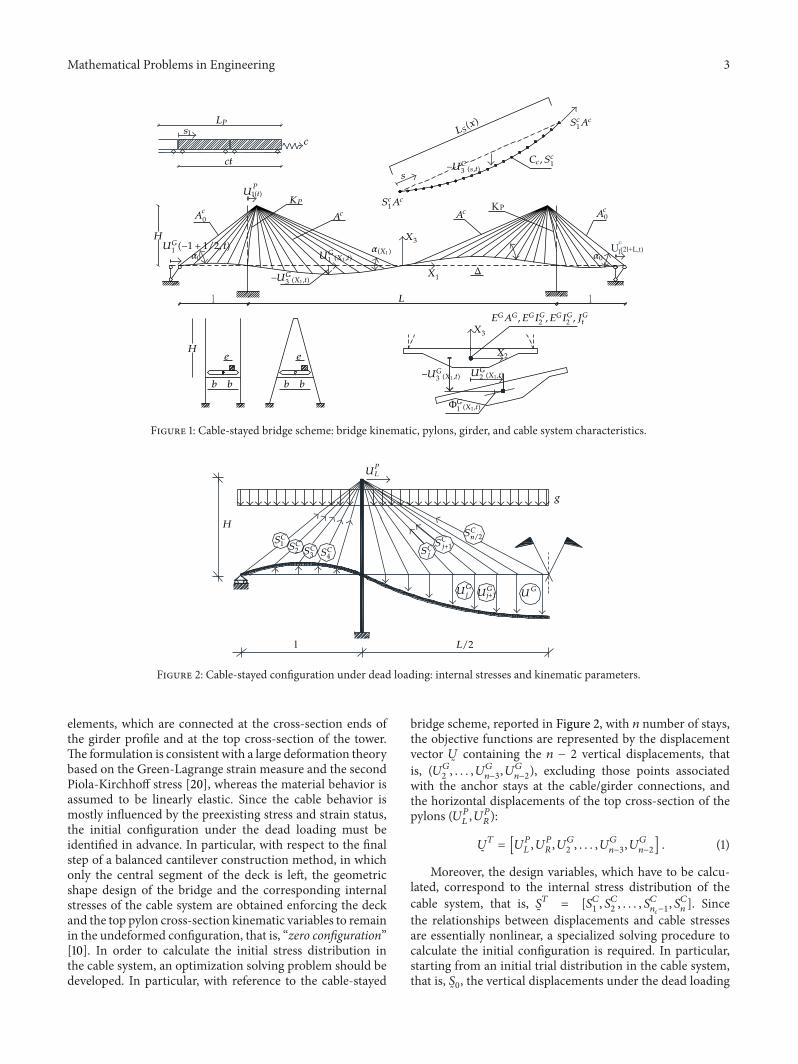
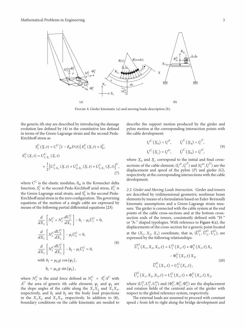
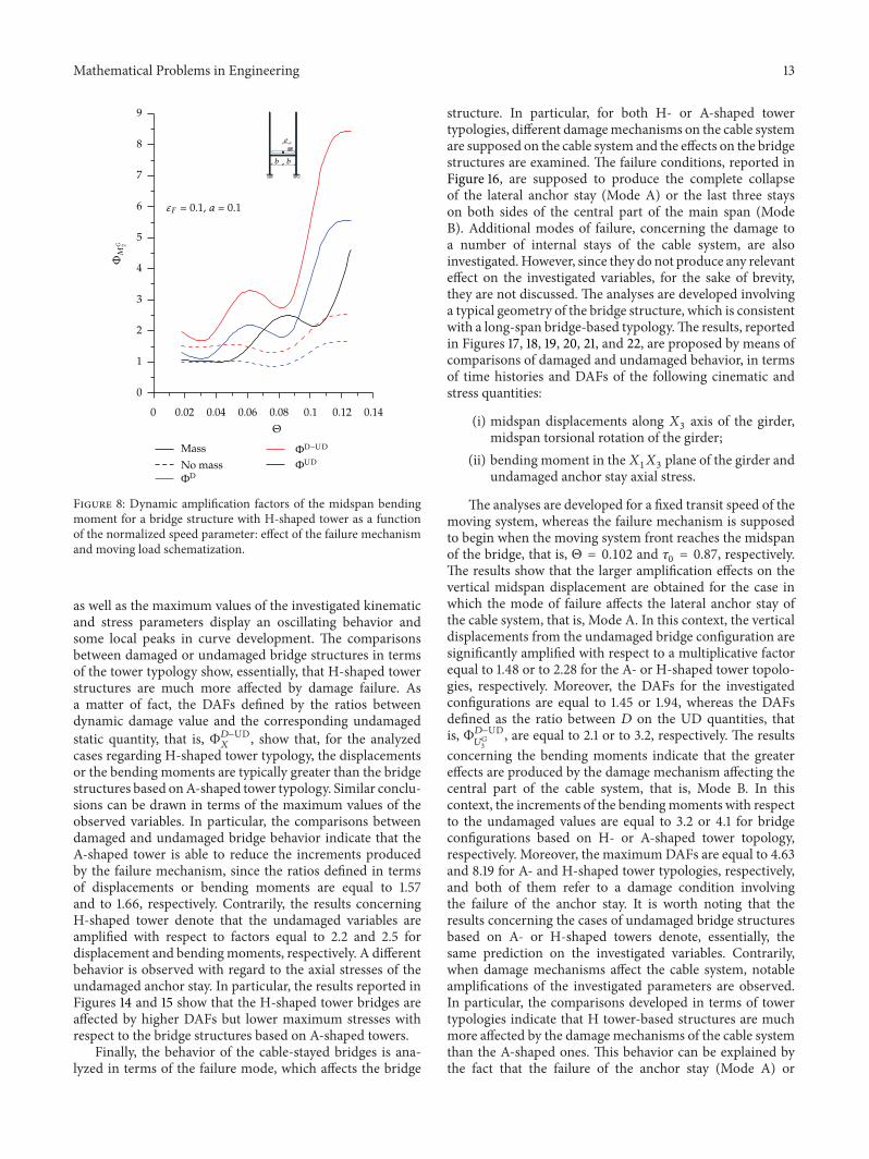
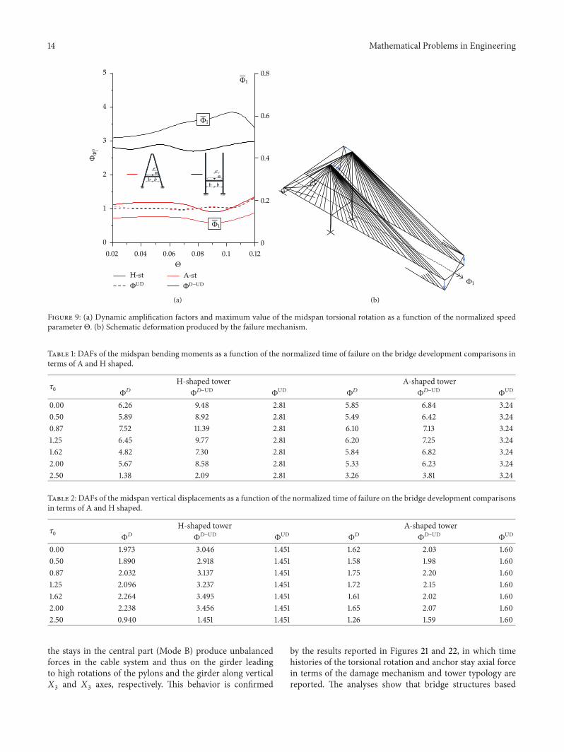
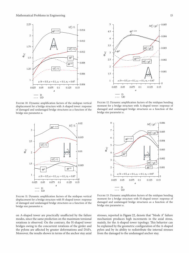
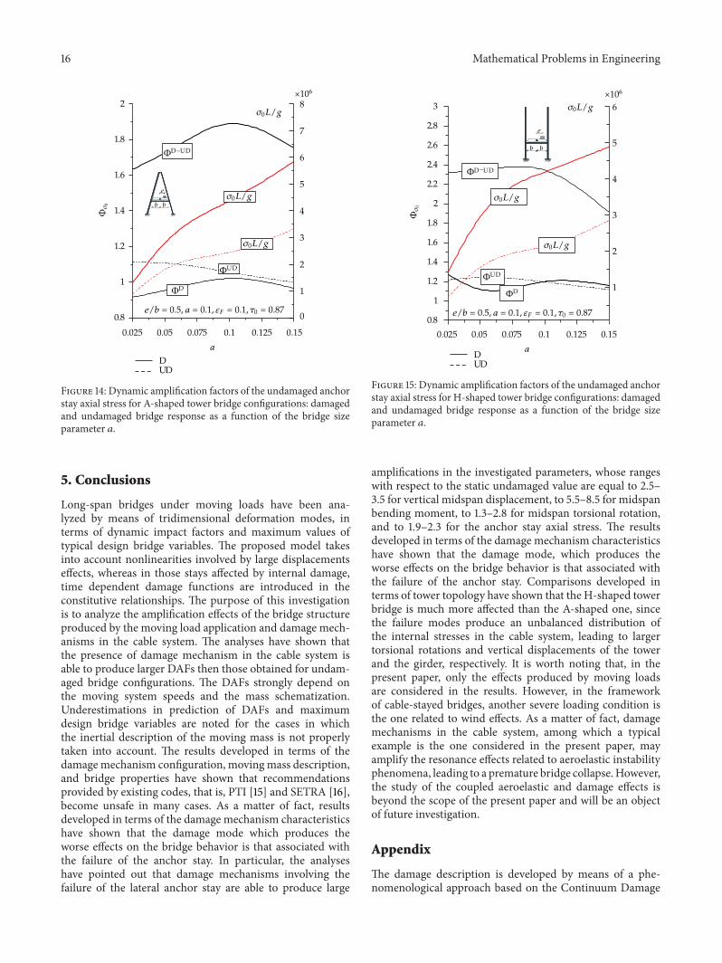