research article effect of the reinforce process on the...
TRANSCRIPT
Research ArticleEffect of the Reinforce Process on the Fatigue FractureProperties of Aeronautical Polymethyl Methacrylate
Wei Shang,1 Xiao-jing Yang,2 Xin-hua Ji,3 and Zhong-xian Liu1
1Key Laboratory of Protection and Retrofitting for Civil Building and Construction of Tianjin, Tianjin Chengjian University,Tianjin 300384, China2School of Materials Science and Engineering, Hebei University of Technology, Tianjin 300130, China3Department of Mechanics, Tianjin University, Tianjin 300072, China
Correspondence should be addressed to Wei Shang; [email protected]
Received 11 March 2016; Accepted 1 August 2016
Academic Editor: Pavel Lejcek
Copyright © 2016 Wei Shang et al. This is an open access article distributed under the Creative Commons Attribution License,which permits unrestricted use, distribution, and reproduction in any medium, provided the original work is properly cited.
Themain purpose of the present work is to investigate fatigue fracturemechanical properties of aeronautical directional polymethylmethacrylate (PMMA) which has been treated by the directional tensile technology. Firstly, the fatigue cracks growth has beentracked in directional PMMA using the stroboscopic method.Then, the digital photoelasticity with a phase-shifting technique wasused to measure the uniformity of the interlaminar stretching. Based on obtained experimental results, the effect of the directionalstretching on fatigue fracture properties of PMMAwas analyzed. Finally, fatigue fracture properties of laminated directional PMMAwere discussed and comparedwith those ofmonolayer directional PMMA.Results of this work show that the lamination technologycan strengthen the interlayer of directional PMMA and enhance its fatigue fracture properties.
1. Introduction
As early as 1949, Sauer and Hsiao [1, 2] began to studythe crazing in the polymer. At that time, it was knownthat stretched areas of polymethyl methacrylate (PMMA)installed on the top of aircraft cockpit canopies had better ant-icraze properties. Thus, researchers from National Instituteof Standards and Technology of United States embarked onthe development of multiaxially and biaxially hot-stretchedPMMA. In 1953, they successfully manufactured apparatusfor the biaxial stretching and production of directionalPMMA sheets. Since then, directional PMMA has beenextensively used in the manufacture of transparent parts ofaircraft canopies. The directional stretching is conducted asfollows: firstly, PMMA sheets are heated to a temperaturewhich is slightly higher than its glass transition temperature.Then, these sheets are immediately put into the stretchingequipment with fixed fixtures and water-cooling devices.After being stretched to the required strain, the stretchingprocess is over and sheets are cooled under the certain tensileforce. Finally, directional PMMA sheets are obtained whose
molecular chains are in an oriented state. Since directionalPMMA has oriented molecular chains, the properties aresignificantly improved to unstretched PMMA.
Fatigue fracture properties of transparent parts of aircraftcanopies play a crucial role in the safe flight performance ofan aircraft. Mukherjee and Burns [3] proposed that fatiguebehaviors of PMMA were determined by three parameters:stress intensity factor amplitude, average stress intensityfactor, and frequency. Cheng et al. [4] studied the influenceof the temperature and frequency on the fatigue crackpropagation behavior of PMMA. Kim [5, 6] proposed thatthe fatigue crack growth rate ofmost polymers increasedwiththe temperature increasing and decreased with the loadingfrequency increasing. Ramsteiner and Armbrust [7] solvedsome fatigue experimental questions of polymers such asthe measurement of the crack propagation, the influenceof the specimen shape and the applied frequency, and themeasurement with the constant or increasing stress intensityamplitude. Yao et al. [8, 9] investigated the dynamic fracturebehavior of thin PMMA plates with the assistance of a high-speed camera. Sahraoui et al. [10] measured the dynamic
Hindawi Publishing CorporationAdvances in Materials Science and EngineeringVolume 2016, Article ID 7126854, 9 pageshttp://dx.doi.org/10.1155/2016/7126854
2 Advances in Materials Science and Engineering
(a) (b)
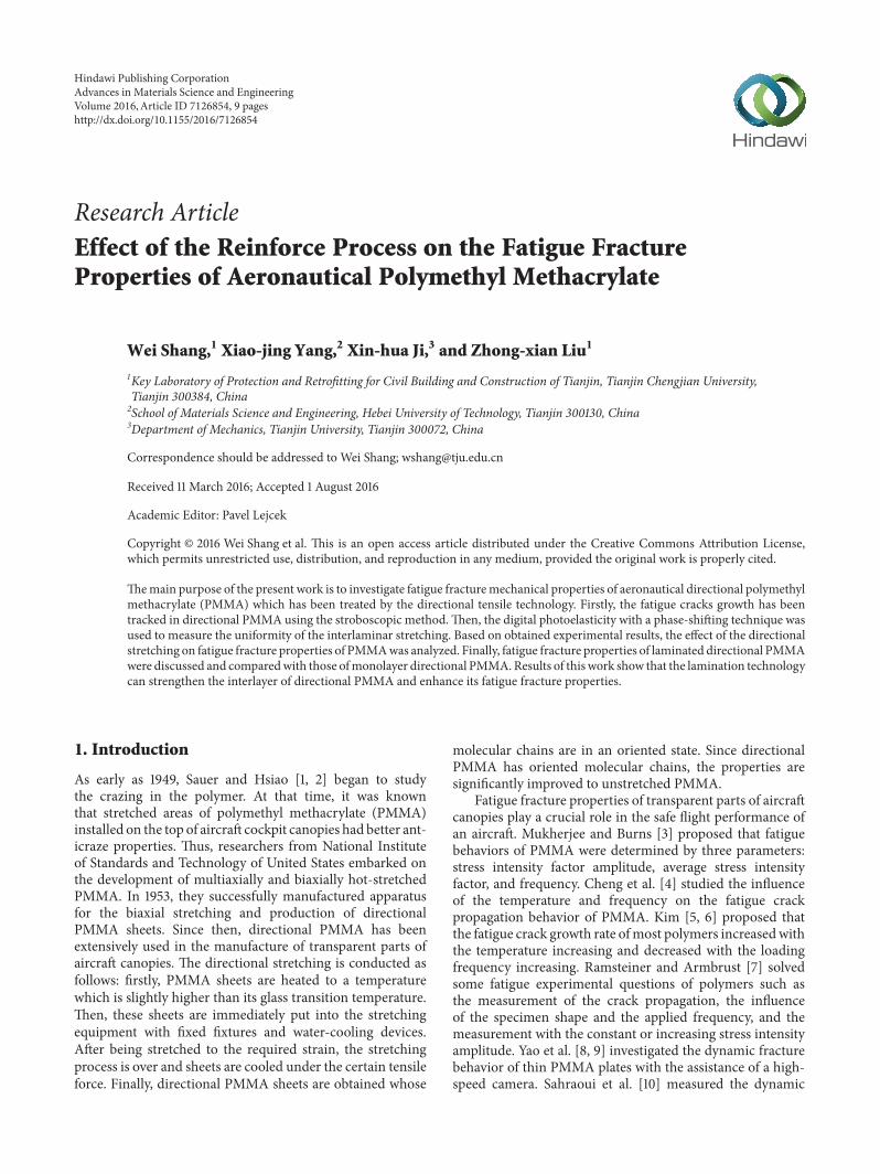
Figure 1: Gray distribution images of the specimen surface. (a) One acquisition; (b) twice light intensity superposition.
fracture toughness of notched PMMA at high impact veloc-ities. The direct measurements of the specimen deflectionare successfully used for the toughness evaluation. Liu et al.[11] investigated evolution of ratcheting strains of PMMA atdifferent temperatures and stress levels by the experiment.
Currently, fatigue properties of PMMA were studiedprimarily based on the isotropic assumption. The author hasproposed an anisotropic mechanical model for directionalPMMA [12]. This research tracked the growth of fatiguecracks in directional PMMAby a stroboscopicmethod.Then,the digital photoelasticitywith a phase-shifting techniquewasused to test the uniformity of the interlaminar stretching.Finally, based on obtained experimental results, the effect ofthe directional stretching on fatigue fracture properties ofdirectional PMMA was analyzed.
2. Test of Fatigue Fracture Properties byStroboscopic Method
The stroboscopic method is based on the following principle.The flash frequency is adjusted to be equal to the motionfrequency of the tested object, so that the same position ofthe tested object is seen every time. For periodic motionspecimens, when they are exposed to the stroboscopic lightwith extremely short duration pulses at a flash frequencyequal to the frequency of the motion, the specimens alwaysreach the same position every time. Therefore, the obtainedpicture is a stationary image (i.e., it is position invariant).When the lighting time is short enough, moving specimenscan only move within a small range and can be regarded asthe stationary. In this way, we can obtain images of specimensat the moment of the movement.
The stroboscopic method does not require a high-speedcamera. A simple charge coupled device (CCD) camera canbe used. The CCD camera generally has exposure times ofapproximately 30ms, so images of moving specimens areblurred and cannot reflect the movement of specimens atthe certain position. The stroboscopic method can be usedto solve this problem. According to the exposure time of theCCD camera, the stroboscopic light flashes for a very shorttime and can be adjusted to the duration of less than 10 𝜇s.
Owing to the short illumination period, the CCD cameracannot acquire the sufficient light to produce clear images ina stroboscopic flash. Therefore, the CCD camera can acquirethe sufficient light to produce clear images after many flashesat the same position. Currently, the stroboscopic methodhas been successfully applied to investigate the vibration ofmicroelectromechanical systems (MEMS) [13–16].
With the increase in number of cycles, positions of thespecimen change under the fatigue load; however, since thetest is conducted over a long time, positions of the specimencan be considered as invariant at the same moment inadjacent cycle periods.Therefore, we can superimpose imagesacquired at the same moment in adjacent cycle periods.According to the above requirements, the image acquisitionsoftware was programmed based on the principle of theintensity superposition. During the illumination process, oneframe image was collected, followed by another frame image.Then, gray values of these two images at correspondingpositions were superimposed. This process was repeatedlyconducted until clear imageswere acquired. Figure 1(a) showsimages obtained through one acquisition, and Figure 1(b)shows twice light intensity superposition. As seen, the graydistribution of the image obtained through two superpositionoperations is clearer than that acquired through one.
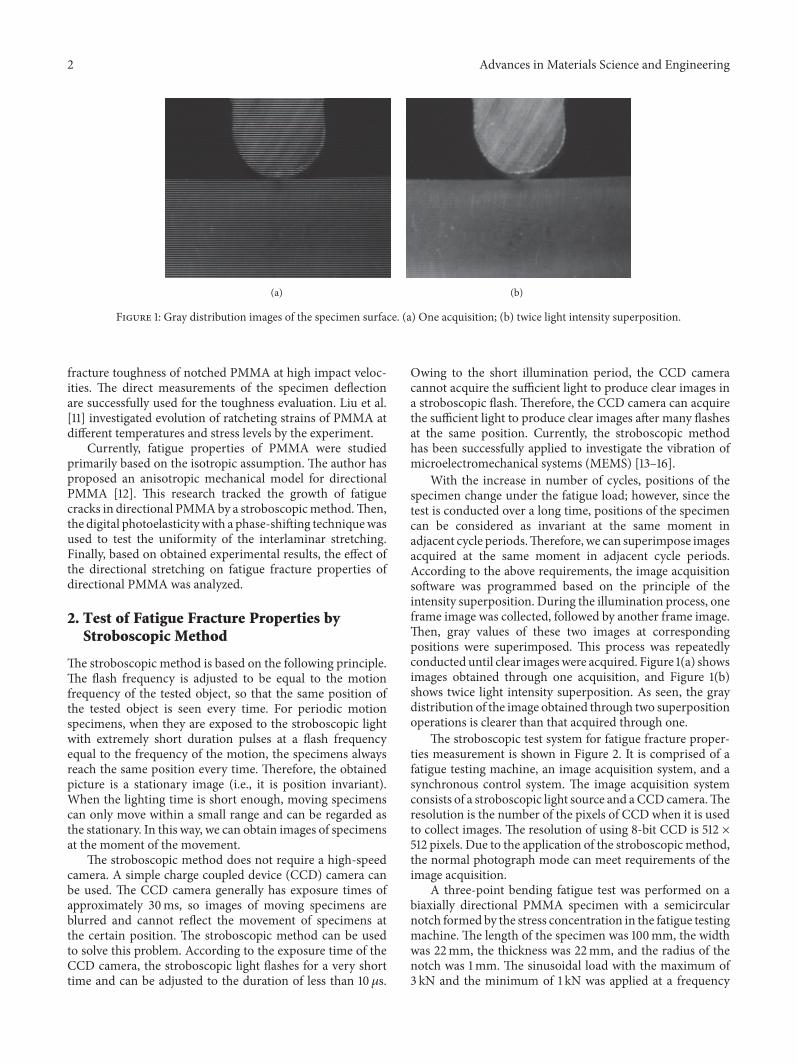
The stroboscopic test system for fatigue fracture proper-ties measurement is shown in Figure 2. It is comprised of afatigue testing machine, an image acquisition system, and asynchronous control system. The image acquisition systemconsists of a stroboscopic light source and aCCDcamera.Theresolution is the number of the pixels of CCD when it is usedto collect images. The resolution of using 8-bit CCD is 512 ×512 pixels. Due to the application of the stroboscopicmethod,the normal photograph mode can meet requirements of theimage acquisition.
A three-point bending fatigue test was performed on abiaxially directional PMMA specimen with a semicircularnotch formed by the stress concentration in the fatigue testingmachine. The length of the specimen was 100mm, the widthwas 22mm, the thickness was 22mm, and the radius of thenotch was 1mm. The sinusoidal load with the maximum of3 kN and the minimum of 1 kN was applied at a frequency
Advances in Materials Science and Engineering 3
Stroboscopic test system
Fatigue testing machine
CCD
Specimen
Stroboscopic light source
Figure 2: Fatigue test system for the stroboscope method.
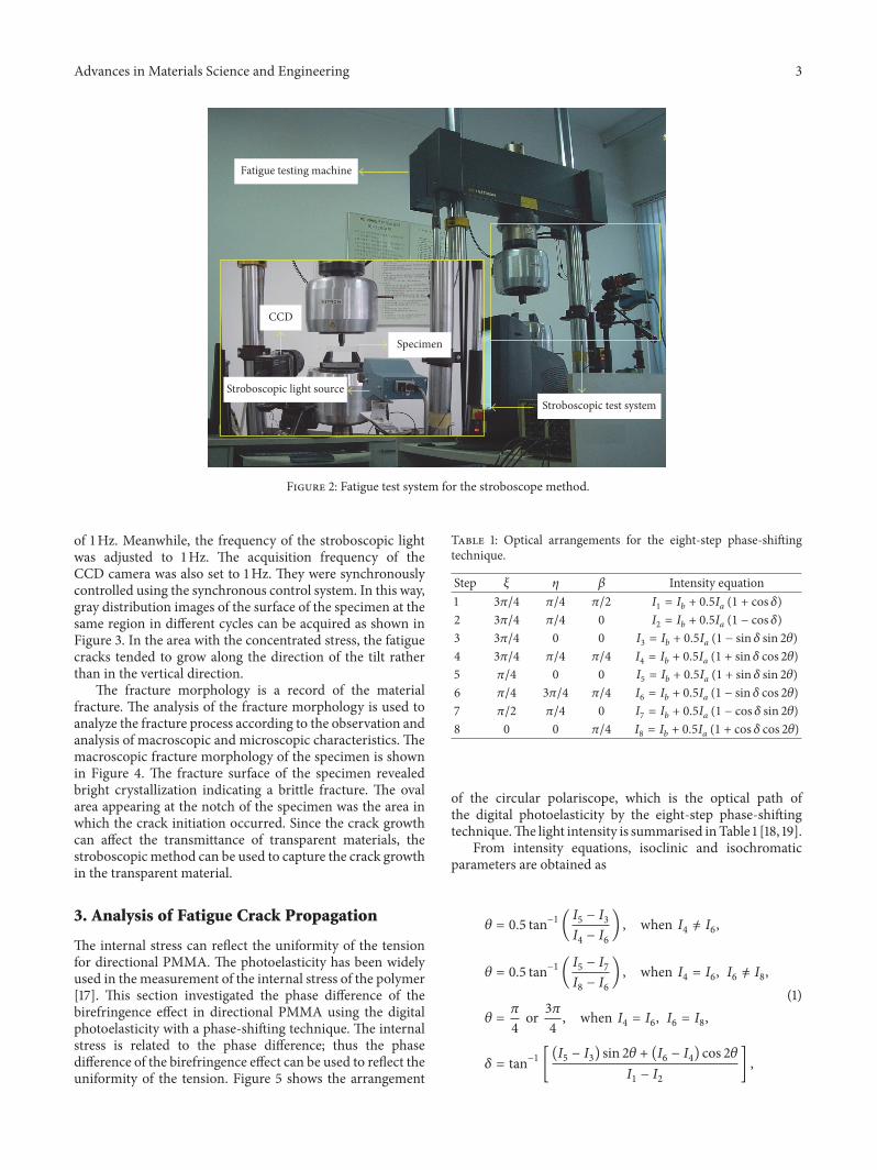
of 1Hz. Meanwhile, the frequency of the stroboscopic lightwas adjusted to 1Hz. The acquisition frequency of theCCD camera was also set to 1Hz. They were synchronouslycontrolled using the synchronous control system. In this way,gray distribution images of the surface of the specimen at thesame region in different cycles can be acquired as shown inFigure 3. In the area with the concentrated stress, the fatiguecracks tended to grow along the direction of the tilt ratherthan in the vertical direction.
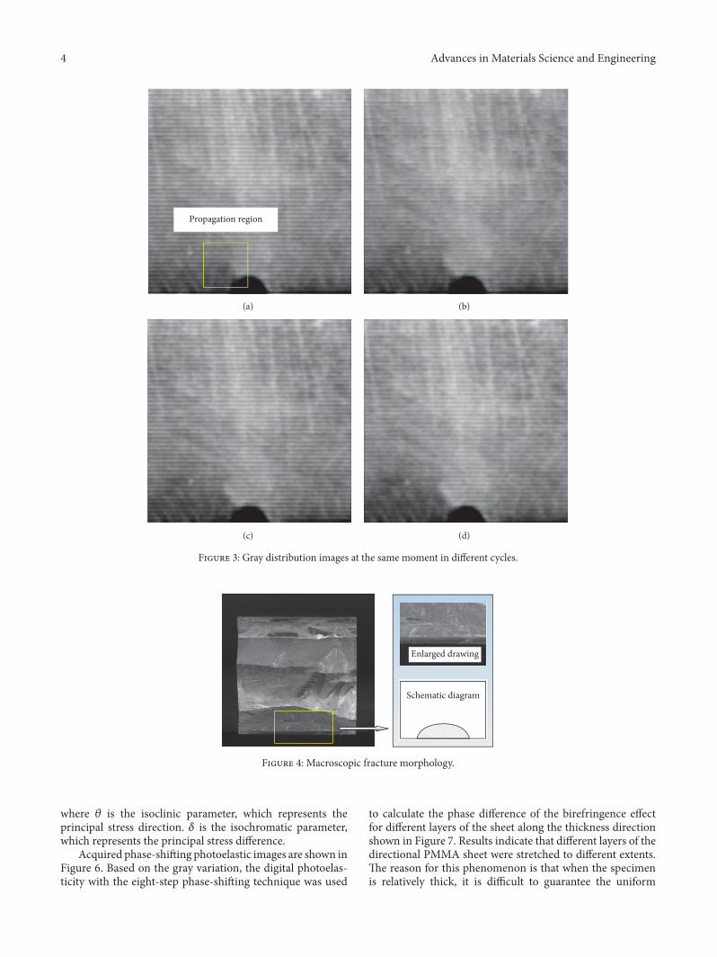
The fracture morphology is a record of the materialfracture. The analysis of the fracture morphology is used toanalyze the fracture process according to the observation andanalysis of macroscopic and microscopic characteristics. Themacroscopic fracture morphology of the specimen is shownin Figure 4. The fracture surface of the specimen revealedbright crystallization indicating a brittle fracture. The ovalarea appearing at the notch of the specimen was the area inwhich the crack initiation occurred. Since the crack growthcan affect the transmittance of transparent materials, thestroboscopicmethod can be used to capture the crack growthin the transparent material.
3. Analysis of Fatigue Crack Propagation
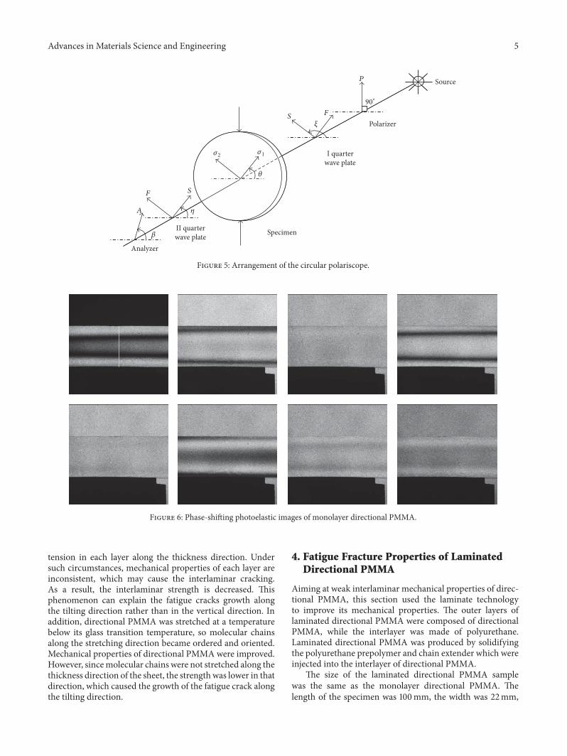
The internal stress can reflect the uniformity of the tensionfor directional PMMA. The photoelasticity has been widelyused in the measurement of the internal stress of the polymer[17]. This section investigated the phase difference of thebirefringence effect in directional PMMA using the digitalphotoelasticity with a phase-shifting technique. The internalstress is related to the phase difference; thus the phasedifference of the birefringence effect can be used to reflect theuniformity of the tension. Figure 5 shows the arrangement
Table 1: Optical arrangements for the eight-step phase-shiftingtechnique.
Step 𝜉 𝜂 𝛽 Intensity equation1 3𝜋/4 𝜋/4 𝜋/2 𝐼1 = 𝐼𝑏 + 0.5𝐼𝑎 (1 + cos 𝛿)2 3𝜋/4 𝜋/4 0 𝐼2 = 𝐼𝑏 + 0.5𝐼𝑎 (1 − cos 𝛿)3 3𝜋/4 0 0 𝐼3 = 𝐼𝑏 + 0.5𝐼𝑎 (1 − sin 𝛿 sin 2𝜃)4 3𝜋/4 𝜋/4 𝜋/4 𝐼4 = 𝐼𝑏 + 0.5𝐼𝑎 (1 + sin 𝛿 cos 2𝜃)5 𝜋/4 0 0 𝐼5 = 𝐼𝑏 + 0.5𝐼𝑎 (1 + sin 𝛿 sin 2𝜃)6 𝜋/4 3𝜋/4 𝜋/4 𝐼6 = 𝐼𝑏 + 0.5𝐼𝑎 (1 − sin 𝛿 cos 2𝜃)7 𝜋/2 𝜋/4 0 𝐼7 = 𝐼𝑏 + 0.5𝐼𝑎 (1 − cos 𝛿 sin 2𝜃)8 0 0 𝜋/4 𝐼8 = 𝐼𝑏 + 0.5𝐼𝑎 (1 + cos 𝛿 cos 2𝜃)
of the circular polariscope, which is the optical path ofthe digital photoelasticity by the eight-step phase-shiftingtechnique.The light intensity is summarised inTable 1 [18, 19].
From intensity equations, isoclinic and isochromaticparameters are obtained as
𝜃 = 0.5 tan−1 (𝐼5 − 𝐼3𝐼4 − 𝐼6) , when 𝐼4 = 𝐼6,
𝜃 = 0.5 tan−1 (𝐼5 − 𝐼7𝐼8 − 𝐼6) , when 𝐼4 = 𝐼6, 𝐼6 = 𝐼8,
𝜃 = 𝜋4 or3𝜋4 , when 𝐼4 = 𝐼6, 𝐼6 = 𝐼8,
𝛿 = tan−1 [(𝐼5 − 𝐼3) sin 2𝜃 + (𝐼6 − 𝐼4) cos 2𝜃𝐼1 − 𝐼2 ] ,
(1)
4 Advances in Materials Science and Engineering
Propagation region
(a) (b)
(c) (d)
Figure 3: Gray distribution images at the same moment in different cycles.
Enlarged drawing
Schematic diagram
Figure 4: Macroscopic fracture morphology.
where 𝜃 is the isoclinic parameter, which represents theprincipal stress direction. 𝛿 is the isochromatic parameter,which represents the principal stress difference.
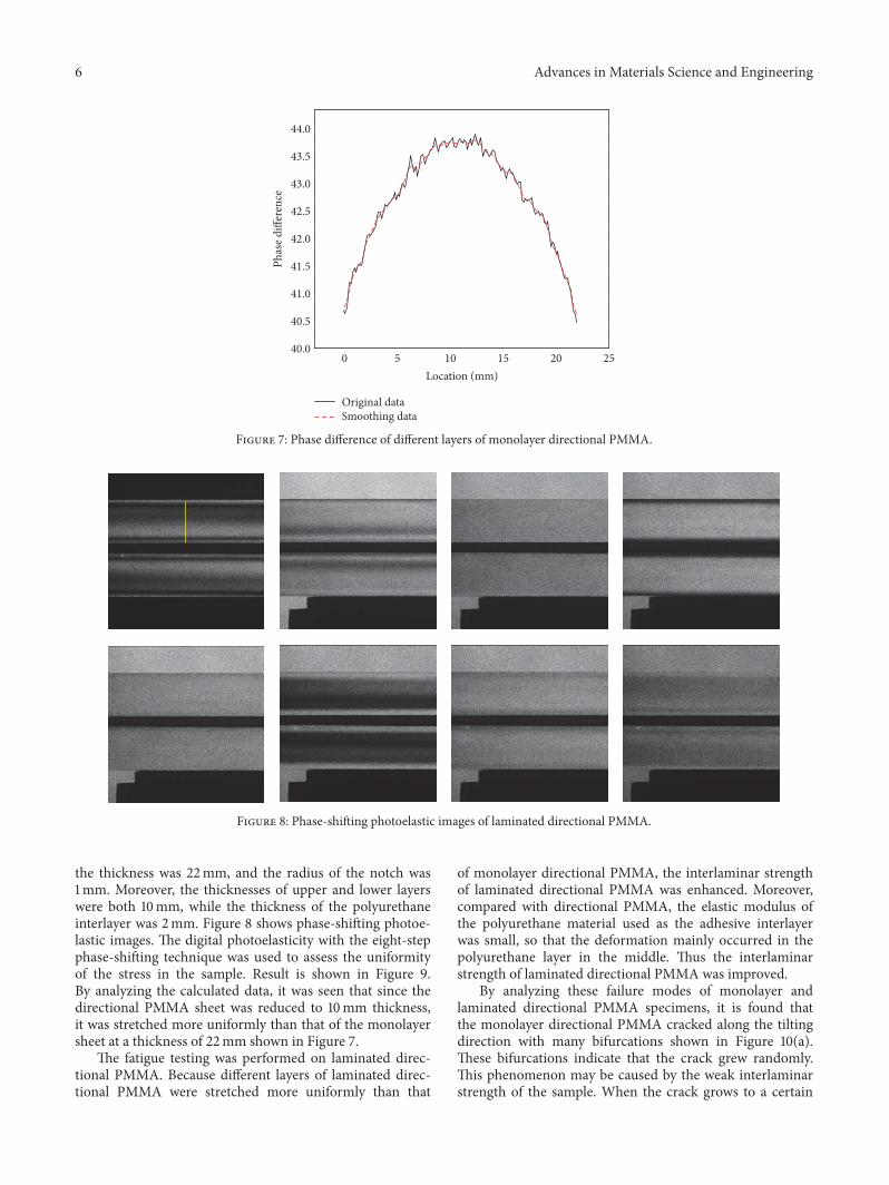
Acquired phase-shifting photoelastic images are shown inFigure 6. Based on the gray variation, the digital photoelas-ticity with the eight-step phase-shifting technique was used
to calculate the phase difference of the birefringence effectfor different layers of the sheet along the thickness directionshown in Figure 7. Results indicate that different layers of thedirectional PMMA sheet were stretched to different extents.The reason for this phenomenon is that when the specimenis relatively thick, it is difficult to guarantee the uniform
Advances in Materials Science and Engineering 5
Analyzer
II quarterwave plate Specimen
I quarterwave plate
Polarizer
Source
𝛽
A
F S
𝜂
𝜎2 𝜎1
𝜃
S F
𝜉
P
90∘
Figure 5: Arrangement of the circular polariscope.
Figure 6: Phase-shifting photoelastic images of monolayer directional PMMA.
tension in each layer along the thickness direction. Undersuch circumstances, mechanical properties of each layer areinconsistent, which may cause the interlaminar cracking.As a result, the interlaminar strength is decreased. Thisphenomenon can explain the fatigue cracks growth alongthe tilting direction rather than in the vertical direction. Inaddition, directional PMMA was stretched at a temperaturebelow its glass transition temperature, so molecular chainsalong the stretching direction became ordered and oriented.Mechanical properties of directional PMMA were improved.However, sincemolecular chains were not stretched along thethickness direction of the sheet, the strengthwas lower in thatdirection, which caused the growth of the fatigue crack alongthe tilting direction.
4. Fatigue Fracture Properties of LaminatedDirectional PMMA
Aiming at weak interlaminar mechanical properties of direc-tional PMMA, this section used the laminate technologyto improve its mechanical properties. The outer layers oflaminated directional PMMA were composed of directionalPMMA, while the interlayer was made of polyurethane.Laminated directional PMMA was produced by solidifyingthe polyurethane prepolymer and chain extender which wereinjected into the interlayer of directional PMMA.
The size of the laminated directional PMMA samplewas the same as the monolayer directional PMMA. Thelength of the specimen was 100mm, the width was 22mm,
6 Advances in Materials Science and Engineering
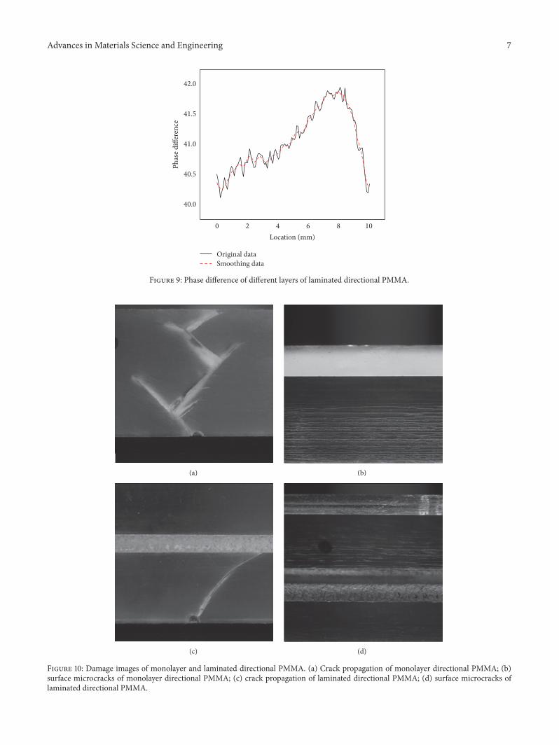
0 5 10 15 20 2540.0
40.5
41.0
41.5
42.0
42.5
43.0
43.5
44.0
Phas
e diff
eren
ce
Location (mm)
Original dataSmoothing data
Figure 7: Phase difference of different layers of monolayer directional PMMA.
Figure 8: Phase-shifting photoelastic images of laminated directional PMMA.
the thickness was 22mm, and the radius of the notch was1mm. Moreover, the thicknesses of upper and lower layerswere both 10mm, while the thickness of the polyurethaneinterlayer was 2mm. Figure 8 shows phase-shifting photoe-lastic images. The digital photoelasticity with the eight-stepphase-shifting technique was used to assess the uniformityof the stress in the sample. Result is shown in Figure 9.By analyzing the calculated data, it was seen that since thedirectional PMMA sheet was reduced to 10mm thickness,it was stretched more uniformly than that of the monolayersheet at a thickness of 22mm shown in Figure 7.
The fatigue testing was performed on laminated direc-tional PMMA. Because different layers of laminated direc-tional PMMA were stretched more uniformly than that
of monolayer directional PMMA, the interlaminar strengthof laminated directional PMMA was enhanced. Moreover,compared with directional PMMA, the elastic modulus ofthe polyurethane material used as the adhesive interlayerwas small, so that the deformation mainly occurred in thepolyurethane layer in the middle. Thus the interlaminarstrength of laminated directional PMMA was improved.
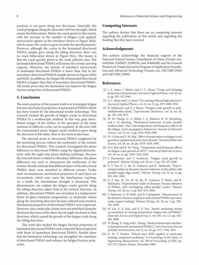
By analyzing these failure modes of monolayer andlaminated directional PMMA specimens, it is found thatthe monolayer directional PMMA cracked along the tiltingdirection with many bifurcations shown in Figure 10(a).These bifurcations indicate that the crack grew randomly.This phenomenon may be caused by the weak interlaminarstrength of the sample. When the crack grows to a certain
Advances in Materials Science and Engineering 7
0 2 4 6 8 10
40.0
40.5
41.0
41.5
42.0
Phas
e diff
eren
ce
Location (mm)
Original dataSmoothing data
Figure 9: Phase difference of different layers of laminated directional PMMA.
(a) (b)
(c) (d)
Figure 10: Damage images of monolayer and laminated directional PMMA. (a) Crack propagation of monolayer directional PMMA; (b)surface microcracks of monolayer directional PMMA; (c) crack propagation of laminated directional PMMA; (d) surface microcracks oflaminated directional PMMA.
8 Advances in Materials Science and Engineering
position, it can grow along two directions. Generally, thecrack propagates along the directionwith less strength, whichcauses the bifurcations. Before the crack grows to this extent,with the increase in the number of fatigue cycle applied,microcracks appear in the interlayer shown in Figure 10(b),which causes the cracks to grow towards the interlamination.However, although the cracks in the laminated directionalPMMA sample grew along the tilting direction, there wasno crack bifurcation shown in Figure 10(c). The reason isthat the crack quickly grows to the weak adhesive area. Thelaminated directional PMMA still retains the certain carryingcapacity. Moreover, the density of interlayer microcracksin laminated directional PMMA is lower than that in themonolayer directional PMMA sample shown in Figures 10(b)and 10(d). In addition, the fatigue life of laminated directionalPMMA is higher than that of monolayer directional PMMA.All results prove that the lamination can improve the fatiguefracture properties of directional PMMA.
5. Conclusion
Themain purpose of the present work is to investigate fatiguefracture mechanical properties of aeronautical PMMAwhichhas been treated by the directional tensile technology. Thisresearch tracked the growth of fatigue cracks in directionalPMMA by a stroboscopic method. In this way, gray distri-bution images of the surface of the specimen at the samemoment in different cycles can be acquired. In the area withthe concentrated stress, fatigue cracks tended to grow alongthe direction of tilt rather than in the vertical direction.
The internal stress in directional PMMA toughened bythe stretching process reflects the uniformity of the tensionfor directional PMMA. This research investigated the phasedifference in directional PMMA using the digital photoelas-ticity with the eight-step phase-shifting technique. Becausethe internal stress is related to the phase difference, the phasedifference was used to characterize the uniformity of thetension. Results indicate that different layers of the directionalPMMA sheet were stretched to different extents. Undersuch circumstances, mechanical properties of each layer areinconsistent, which may cause the interlaminar cracking.As a result, the interlaminar strength is decreased. Thisphenomenon can explain the fatigue cracks growth alongthe tilting direction rather than in the vertical direction. Inaddition, directional PMMA was stretched at a temperaturebelow its glass transition temperature, so molecular chainsalong the stretching direction became ordered and oriented.Mechanical properties of directional PMMA were improved.However, sincemolecular chains were not stretched along thethickness direction of the sheet, the strengthwas lower in thatdirection, which caused the growth of the fatigue crack alongthe tilting direction.
This work also studied the fatigue fracture properties oflaminated directional PMMA and compared these propertieswith those of monolayer directional PMMA. Results showthat the lamination technology can strengthen the interlayerof directional PMMA and enhance its fatigue fracture prop-erties.
Competing Interests
The authors declare that there are no competing interestsregarding the publication of this article and regarding thefunding that they have received.
Acknowledgments
The authors acknowledge the financial support of theNational Natural Science Foundation of China (Grants nos.11402166, 51301057, 51208336, and 51408400) and the GeneralProjects in Tianjin Research Programof Application Founda-tion and Advanced Technology (Grants nos. 13JCYBJC39100and 14JCYBJC21900).
References
[1] J. A. Sauer, J. Marin, and C. C. Hsiao, “Creep and dampingproperties of polystyrene,” Journal of Applied Physics, vol. 20, no.6, pp. 507–517, 1949.
[2] C.C.Hsiao and J. A. Sauer, “On crazing of linear high polymers,”Journal of Applied Physics, vol. 21, no. 11, pp. 1071–1083, 1950.
[3] B. Mukherjee and D. J. Burns, “Fatigue-crack growth in poly-methylmethacrylate,” Experimental Mechanics, vol. 11, no. 10,pp. 433–439, 1971.
[4] W. M. Cheng, G. A. Miller, J. A. Manson, R. W. Hertzberg,and L. H. Sperling, “Mechanical behaviour of poly (methylmethacrylate). Part 2 the temperature and frequency effects onthe fatigue crack propagation behaviour,” Journal of MaterialsScience, vol. 25, no. 4, pp. 1924–1930, 1990.
[5] H.-S. Kim andY.-W.Mai, “Effect of temperature on fatigue crackgrowth in unplasticized polyvinyl chloride,” Journal ofMaterialsScience, vol. 28, no. 20, pp. 5479–5485, 1993.
[6] H. S. Kim and X. M.Wang, “Temperature and frequency effectson fatigue crack growth of uPVC,” Journal of Materials Science,vol. 29, no. 12, pp. 3209–3214, 1994.
[7] F. Ramsteiner and T. Armbrust, “Fatigue crack growth inpolymers,” Polymer Testing, vol. 20, no. 3, pp. 321–327, 2001.
[8] X. F. Yao, G. C. Jin, K. Arakawa, and K. Takahashi, “Experi-mental studies on dynamic fracture behavior of thin plates withparallel single edge cracks,” Polymer Testing, vol. 21, no. 8, pp.933–940, 2002.
[9] X. F. Yao, W. Xu, M. Q. Xu, K. Arakawa, T. Mada, and K.Takahashi, “Experimental study of dynamic fracture behaviorof PMMA with overlapping offset-parallel cracks,” PolymerTesting, vol. 22, no. 6, pp. 663–670, 2003.
[10] S. Sahraoui, A. El Mahi, and B. Castagnede, “Measurement ofthe dynamic fracture toughness with notched PMMA specimenunder impact loading,” Polymer Testing, vol. 28, no. 7, pp. 780–783, 2009.
[11] W. Liu, Z. Z. Gao, and Z. F. Yue, “Steady ratcheting strainsaccumulation in varying temperature fatigue tests of PMMA,”Materials Science and Engineering A, vol. 492, no. 1-2, pp. 102–109, 2008.
[12] W. Shang, X. Yang, and L. Zhang, “Study of anisotropicmechan-ical properties for aeronautical PMMA,” LatinAmerican Journalof Solids and Structures, vol. 11, no. 10, pp. 1777–1790, 2014.
[13] R. W. T. Preater, “Pulsed laser ESPI applied to particularrotating component problems,” in Proceedings of the Optics inEngineering Measurement, vol. 599 of Proceedings of SPIE, pp.174–177, Cannes, France, November 1985.
Advances in Materials Science and Engineering 9
[14] J. P. Sikora, “Deflection of rotating marine propellers usingprojected-grating moire techniques,” Experimental Mechanics,vol. 21, no. 12, pp. 456–460, 1981.
[15] M. R. Hart, R. A. Conant, K. Y. Lau, and R. S. Muller,“Stroboscopic interferometer system for dynamic MEMS char-acterization,” Journal of Microelectromechanical Systems, vol. 9,no. 4, pp. 409–418, 2000.
[16] C. Rembe, B. Tibken, and E. P. Hofer, “Analysis of the dynamicsin microactuators using high-speed cine photomicrography,”Journal of Microelectromechanical Systems, vol. 10, no. 1, pp. 137–145, 2001.
[17] X.-C. Zhang, H.-W. Ji, and Z.-X. Qiao, “Residual stress in self-healing microcapsule-loaded epoxy,”Materials Letters, vol. 137,pp. 9–12, 2014.
[18] W. Shang, X. Ji, and X. Yang, “Study on several problems ofautomatic full-field isoclinic parameter measurement by digitalphase shifting photoelasticity,” Optik, vol. 126, no. 19, pp. 1981–1985, 2015.
[19] P. Pinit and E. Umezaki, “Digitally whole-field analysis ofisoclinic parameter in photoelasticity by four-step color phase-shifting technique,”Optics and Lasers in Engineering, vol. 45, no.7, pp. 795–807, 2007.

Submit your manuscripts athttp://www.hindawi.com
ScientificaHindawi Publishing Corporationhttp://www.hindawi.com Volume 2014
CorrosionInternational Journal of
Hindawi Publishing Corporationhttp://www.hindawi.com Volume 2014
Polymer ScienceInternational Journal of
Hindawi Publishing Corporationhttp://www.hindawi.com Volume 2014
Hindawi Publishing Corporationhttp://www.hindawi.com Volume 2014
CeramicsJournal of
Hindawi Publishing Corporationhttp://www.hindawi.com Volume 2014
CompositesJournal of
NanoparticlesJournal of
Hindawi Publishing Corporationhttp://www.hindawi.com Volume 2014
Hindawi Publishing Corporationhttp://www.hindawi.com Volume 2014
International Journal of
Biomaterials
Hindawi Publishing Corporationhttp://www.hindawi.com Volume 2014
NanoscienceJournal of
TextilesHindawi Publishing Corporation http://www.hindawi.com Volume 2014
Journal of
NanotechnologyHindawi Publishing Corporationhttp://www.hindawi.com Volume 2014
Journal of
CrystallographyJournal of
Hindawi Publishing Corporationhttp://www.hindawi.com Volume 2014
The Scientific World JournalHindawi Publishing Corporation http://www.hindawi.com Volume 2014
Hindawi Publishing Corporationhttp://www.hindawi.com Volume 2014
CoatingsJournal of
Advances in
Materials Science and EngineeringHindawi Publishing Corporationhttp://www.hindawi.com Volume 2014
Smart Materials Research
Hindawi Publishing Corporationhttp://www.hindawi.com Volume 2014
Hindawi Publishing Corporationhttp://www.hindawi.com Volume 2014
MetallurgyJournal of
Hindawi Publishing Corporationhttp://www.hindawi.com Volume 2014
BioMed Research International
MaterialsJournal of
Hindawi Publishing Corporationhttp://www.hindawi.com Volume 2014
Nano
materials
Hindawi Publishing Corporationhttp://www.hindawi.com Volume 2014
Journal ofNanomaterials