research article investigation of stress concentration and
TRANSCRIPT

Research ArticleInvestigation of Stress Concentration and Casing StrengthDegradation Caused by Corrosion Pits
Wei Yan Yun Xu Yi Zhou and Kongyang Wang
State Key Laboratory of Petroleum Resources and Prospecting China University of Petroleum Beijing China
Correspondence should be addressed to Wei Yan yanwei289126com
Received 21 July 2016 Accepted 15 September 2016
Academic Editor Ksenija Babic
Copyright copy 2016 Wei Yan et alThis is an open access article distributed under the Creative Commons Attribution License whichpermits unrestricted use distribution and reproduction in any medium provided the original work is properly cited
Downhole casing and tubing are subjected to corrosion in many cases because of the exposure to corrosive environment A moreserious problem is that pitting corrosion occurs in the casing inner surface Meanwhile downhole strings are subjected to variousforms of mechanical loads for example internal pressure load external collapse load or both These loads acting on the corrosionpits will cause stress concentration and degrade the casing strength Thus it is essential to evaluate the stress concentration degreereasonably The SCF (stress concentration factor) is usually used to characterize the degree of stress concentration induced bycorrosion pits This paper presented a comparison on the SCFs regarding the analytical method for a single pit and experimentalmethod for double pitsThe results show that the SCF of a single pit depends mainly on the depth of the corrosion pit however theSCF of the double pits strongly depends on the pits distance A correction factor of 13 was recommended in the double pits SCFprediction model
1 Introduction
Stress concentration is a stress increasing phenomenon inwhich geometric shapes such as cavities and grooves causestress to change dramatically The magnification of thestress concentration usually is expressed by the elastic stressconcentration factor (SCF) SCF calculation model could bedivided into two types one is considered as a semi-infinitebodyhaving a hemispherical pit located on the planersquos surfaceThis problem was systematically presented by Murakami inthe 1980s [1] and he gave the analytical solution Anothermodel is an infinite diameter cylinder with a spherical cavitywhere at the weakest section (excluding the spherical cavity)Timoshenko theory can be used [2] to calculate the SCFTypical corrosion pits in the tubing inner surface are shownin Figure 1 including double hemispherical pits and multiplepits
Based on the stress distribution calculation model ofspherical defect in infinite radius cylinder as shown inFigure 2 the cross profile diagram is shown in Figure 3
According to the theory of elasticity with the infiniteboundary problem (119887 rarr infin) in 119909-119910 plane excluding thedefect the axial load 120590119911 can be calculated as follows [2]
120590119911 = 120590[1 + 4 minus 5]2 (7 minus 5])11988631199033 +
92 (7 minus 5])
11988651199035 ] (1)
where ] is Poissonrsquos ratio 119886 is the radius of the pit 119903 is thedistance to the center of the corrosion pit
Maximum stress 120590119911max appears on the intersecting cir-cumference between the cross sections through the center ofthe pit and the surface of the pit When 119903 = 119886 the maximumaxial stress is
120590119911max = 27 minus 15]2 (7 minus 5])120590 (2)
The stress concentration factor can be defined as
119870 = 27 minus 15]2 (7 minus 5]) (3)
This is different from the plane stressstrain problems stressis related to Poissonrsquos ratio the relationship between stressconcentration factor and Poissonrsquos ratio is shown in Figure 4However Poissonrsquos ratio of steel is between 025 and 03which has a small influence on stress concentration factor
Researchers divide the spherical corrosion defects intothree categories shallow-spherical exact-hemispherical and
Hindawi Publishing CorporationInternational Journal of CorrosionVolume 2016 Article ID 6930234 6 pageshttpdxdoiorg10115520166930234
2 International Journal of Corrosion
Double pits
Multiple pits
Figure 1 Typical pitting corrosion in tubing inner surface
y
120590
120590
2a
2b
z
x
Figure 2 A circular cylinder with a center spherical cavity
deep-spherical defects The term shallow-spherical refers tothe depth of the pit less than the openings radius of the pitthat is ℎ lt 119886 the term exact-hemispherical refers to ℎ = 119886and the term deep-hemispherical refers to ℎ gt 119886 Sun et al[3] calculated stress concentration factors of three types ofcorrosion pits on the basis of the stress concentration factorcalculation method of hemispherical pit in casing proposedby Wang [4] It needs to be stressed that the three modelsof stress concentration plot curves are similar except fora slight difference in the case of small depth of pits Thispaper used the exact-hemispherical (ℎ = 119886) model to givea demonstration (Figure 5)
The revised model of an exact-hemispherical defect SCFis given as follows [5 6]
119870119888hemisphere = [(27 minus 15]) (14 minus 10])]1 minus 1198961 (11988631199053) minus 1198962 (11988651199055) (4)
where
1198961 = minus27 minus 15]14 minus 10] sdot5 minus 4]2(6 minus 4]) (1 + ]) + 25
1198962 = 27 minus 15]14 minus 10] sdot5 minus 4]2(6 minus 4]) (1 + ]) minus 15
(5)
t
y
Rx
z
Figure 3 Spherical cavity in the casing inner surface
025 035 045 055015Poissonrsquos ratio
1
14
18
22
26
3SC
F
Figure 4 The relationship between the stress concentration factorand Poissonrsquos ratio
R
t
0
a
t
x
y
Figure 5 Exact-hemispherical corrosion pit
International Journal of Corrosion 3
d = 3mmd = 6mmd = 9mm
1 2 3 4 5 6 7 8 9 10 11 120Depth of corrosion defect (mm)
0123456789
10
SCF
Figure 6 SCF change with the depth of corrosion pit
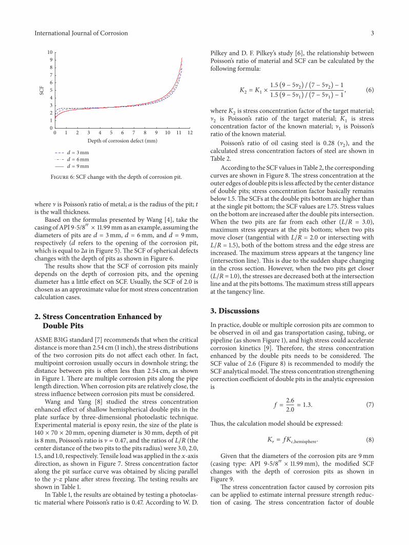
where ] is Poissonrsquos ratio of metal 119886 is the radius of the pit 119905is the wall thickness
Based on the formulas presented by Wang [4] take thecasing ofAPI 9-5810158401015840 times 1199mmas an example assuming thediameters of pits are 119889 = 3mm 119889 = 6mm and 119889 = 9mmrespectively (119889 refers to the opening of the corrosion pitwhich is equal to 2119886 in Figure 5)The SCF of spherical defectschanges with the depth of pits as shown in Figure 6
The results show that the SCF of corrosion pits mainlydepends on the depth of corrosion pits and the openingdiameter has a little effect on SCF Usually the SCF of 20 ischosen as an approximate value for most stress concentrationcalculation cases
2 Stress Concentration Enhanced byDouble Pits
ASME B31G standard [7] recommends that when the criticaldistance is more than 254 cm (1 inch) the stress distributionsof the two corrosion pits do not affect each other In factmultipoint corrosion usually occurs in downhole string thedistance between pits is often less than 254 cm as shownin Figure 1 There are multiple corrosion pits along the pipelength direction When corrosion pits are relatively close thestress influence between corrosion pits must be considered
Wang and Yang [8] studied the stress concentrationenhanced effect of shallow hemispherical double pits in theplate surface by three-dimensional photoelastic techniqueExperimental material is epoxy resin the size of the plate is140 times 70 times 20mm opening diameter is 30mm depth of pitis 8mm Poissonrsquos ratio is ] = 047 and the ratios of 119871119877 (thecenter distance of the two pits to the pits radius) were 30 2015 and 10 respectively Tensile loadwas applied in the 119909-axisdirection as shown in Figure 7 Stress concentration factoralong the pit surface curve was obtained by slicing parallelto the 119910-119911 plane after stress freezing The testing results areshown in Table 1
In Table 1 the results are obtained by testing a photoelas-tic material where Poissonrsquos ratio is 047 According to W D
Pilkey and D F Pilkeyrsquos study [6] the relationship betweenPoissonrsquos ratio of material and SCF can be calculated by thefollowing formula
1198702 = 1198701 times 15 (9 minus 5]2) (7 minus 5]2) minus 115 (9 minus 5]1) (7 minus 5]1) minus 1 (6)
where1198702 is stress concentration factor of the target material]2 is Poissonrsquos ratio of the target material 1198701 is stressconcentration factor of the known material ]1 is Poissonrsquosratio of the known material
Poissonrsquos ratio of oil casing steel is 028 (]2) and thecalculated stress concentration factors of steel are shown inTable 2
According to the SCF values in Table 2 the correspondingcurves are shown in Figure 8 The stress concentration at theouter edges of double pits is less affected by the center distanceof double pits stress concentration factor basically remainsbelow 15The SCFs at the double pits bottom are higher thanat the single pit bottom the SCF values are 175 Stress valueson the bottom are increased after the double pits intersectionWhen the two pits are far from each other (119871119877 = 30)maximum stress appears at the pits bottom when two pitsmove closer (tangential with 119871119877 = 20 or intersecting with119871119877 = 15) both of the bottom stress and the edge stress areincreased The maximum stress appears at the tangency line(intersection line) This is due to the sudden shape changingin the cross section However when the two pits get closer(119871119877 = 10) the stresses are decreased both at the intersectionline and at the pits bottomsThemaximum stress still appearsat the tangency line
3 Discussions
In practice double or multiple corrosion pits are common tobe observed in oil and gas transportation casing tubing orpipeline (as shown Figure 1) and high stress could acceleratecorrosion kinetics [9] Therefore the stress concentrationenhanced by the double pits needs to be considered TheSCF value of 26 (Figure 8) is recommended to modify theSCF analytical modelThe stress concentration strengtheningcorrection coefficient of double pits in the analytic expressionis
119891 = 2620 = 13 (7)
Thus the calculation model should be expressed
119870119903 = 119891119870119888hemisphere (8)
Given that the diameters of the corrosion pits are 9mm(casing type API 9-5810158401015840 times 1199mm) the modified SCFchanges with the depth of corrosion pits as shown inFigure 9
The stress concentration factor caused by corrosion pitscan be applied to estimate internal pressure strength reduc-tion of casing The stress concentration factor of double
4 International Journal of Corrosion
x
R y
e1 e2
1205900
1205900
0
ye1 e2
C
d1 d2
L
P
T
0
z
Figure 7 Shallow-spherical double pits stress concentration photoelastic experiment model
Table 1 Results of photoelastic experiment
Category Center distance ratio Outer edges Pits bottom Junction 119870119900 119870max119871119877 1198701198901 1198701198902 Average 1198701198891 1198701198892 AverageSingle pit 0 122 120 121 193 193
Double pits
10 172 165 168 226 226 226 240 24015 175 172 174 242 237 240 283 28320 155 152 154 222 223 223 279 27930 150 145 148 205 212 209 130 209
Table 2 Double pits stress concentration factor of steel (calculated)
Category Center distance ratio Outer edges Pits bottom Junction 119870119900 119870max119871119877 1198701198901 1198701198902 Average 1198701198891 1198701198892 AverageSingle pit 0 110 109 109 175 175
Double pits
1 156 149 152 204 204 204 217 21715 158 156 157 219 214 217 256 2562 140 137 139 201 202 202 252 2523 136 131 134 185 192 189 118 189
corrosion pits is represented as 119870119903 The revised casing burstpressure prediction model is as follows
119901119887 = 0875 times 2120590119904 ( 11198890)1119870119903 (9)
Taking casing API 9-5810158401015840-N80 as an example theouter diameter is 24447mm the thicknesses are 792mm1003mm and 1199mm respectively and the yield strengthis 552MPa assuming that the opening diameter of corrosionpits in pipe wall is 6mm The stress concentration factorand the casing burst pressure change with the increasingof corrosion pits depth are shown in Figures 10 and 11respectively
The calculation results show that when the pitsrsquo diameteris fixed the degree of stress concentration intensifies withincreasing depth of corrosion pit and when the pit depthreaches half of the wall thickness the SCF factor increasesrapidly Stress concentration has a significant influence on
casing strength In the downhole casing anticorrosion andstrength design stress concentration induced by the doublecorrosion pits needs to be considered reasonably
4 Conclusions
Stress concentration enhanced by double corrosion pits incasing inner surface was studied in this paper The conclu-sions were obtained as follows
(1) The analytical SCF results show that the SCF of ahemispherical corrosion pit is primarily related to thepit depth and the diameter of opening has a littleimpact on SCF The SCF of 20 is used commonly inmost cases
(2) Double or multiple corrosion pits are common inpractice and the distance between the two pits willchange with time during the corrosion process TheSCF strongly depends on pits distance A correction
International Journal of Corrosion 5
Outer edgesPits bottomIntersection line
10
109
175
26
00
05
10
15
20
25
30
SCF
1 2 3 4 5 6 70Pits center distance ratio (LR)
Figure 8 The relationship between stress concentration factor andcavity spacing of steel
Single pitDouble pits
1110 120 21 93 54 86 7Depth of corrosion pits (mm)
0123456789
10
SCF
Figure 9 Modified SCF changing with the depth of corrosion pits(119889 = 9mm)
2 4 6 8 10 120Depth of double corrosion pits (mm)
0
2
4
6
8
10
SCF
t = 792mmt = 1003 mmt = 1199mm
Figure 10 The relationship between pits depth and SCF
2 4 6 8 10 120Depth of pits (mm)
0
10
20
30
40
50
Burs
t pre
ssur
e (M
Pa)
t = 792mmt = 1003 mmt = 1199mm
Figure 11 The relationship between pit depth and burst pressure
factor of 13 was recommended in the double pits SCFprediction model
(3) The stress concentration factor caused by corrosionpits can be applied to estimate internal pressurestrength reduction of casing When the depth of pitreaches half of the wall thickness the SCF factor willincrease faster Stress concentration can degrade thecasing strength obviously
Symbols
] Poissonrsquos ratio]1 Poissonrsquos ratio of the known material]2 Poissonrsquos ratio of the target material119886 Radius of the pit119903 Center distance between the corrosion pits120590119911 Stress at 119911 axis119870 Stress concentration factor119870119888hemisphere SCF of a hemispherical defect model1198701 Stress concentration factor of the known
material1198702 Stress concentration factor of the targetmaterial119870119903 Correction SCF of double pits
Competing Interests
The authors confirm that this articlersquos content has no compet-ing interests
Acknowledgments
This work was financially supported by the National ScienceFoundation of China (Grant no 51504267)
References
[1] YMurakami Stress Intensity FactorHandbook PergamonPressElmsford NY USA 1987
6 International Journal of Corrosion
[2] S P Timoshenko and J M Gere Theory of Elastic StabilityDover Publications 2nd edition 2009
[3] K Sun B Guo and A Ghalambor ldquoCasing strength degrada-tion due to corrosionmdashapplications to casing pressure assess-mentrdquo in Proceedings of the IADCSPE Asia Pacific DrillingTechnology Conference and Exhibition Paper No 88009 Societyof Petroleum Engineers 2004
[4] Q Z Wang ldquoSimple formulae for the stress concentrationfactor for two-and three-dimensional 11 holes in finite domainsrdquoJournal of Strain Analysis vol 37 no 3 pp 259ndash262 2011
[5] Q ZWang ldquoHigh-accuracy expressions of stress concentrationfactor and stress intensity factor in finite domainsrdquo Journal ofMechanical Strength vol 23 no 3 pp 358ndash361 2001 (Chinese)
[6] W D Pilkey and D F Pilkey Petersonrsquos Stress ConcentrationFactors John Wiley amp Sons New York NY USA 3rd edition2008
[7] SME B31G-2009 Manual for Determining the RemainingStrength of Corroded Pipelines American Society ofMechanicalEngineers New York NY USA 2009
[8] J H Wang and T C Yang ldquoStress concentration in slabcaused by two or more shallow spherical hollowsrdquo Journalof Experimeantal Mechanics vol 9 no 3 pp 270ndash274 1994(Chinese)
[9] P Zhu W Yan L Deng and J Deng ldquoThe application ofmechanical-chemical corrosion theory in downhole tubingCO2 corrosion researchrdquo Advances in Materials Science andEngineering vol 2015 Article ID 296278 6 pages 2015
Submit your manuscripts athttpwwwhindawicom
ScientificaHindawi Publishing Corporationhttpwwwhindawicom Volume 2014
CorrosionInternational Journal of
Hindawi Publishing Corporationhttpwwwhindawicom Volume 2014
Polymer ScienceInternational Journal of
Hindawi Publishing Corporationhttpwwwhindawicom Volume 2014
Hindawi Publishing Corporationhttpwwwhindawicom Volume 2014
CeramicsJournal of
Hindawi Publishing Corporationhttpwwwhindawicom Volume 2014
CompositesJournal of
NanoparticlesJournal of
Hindawi Publishing Corporationhttpwwwhindawicom Volume 2014
Hindawi Publishing Corporationhttpwwwhindawicom Volume 2014
International Journal of
Biomaterials
Hindawi Publishing Corporationhttpwwwhindawicom Volume 2014
NanoscienceJournal of
TextilesHindawi Publishing Corporation httpwwwhindawicom Volume 2014
Journal of
NanotechnologyHindawi Publishing Corporationhttpwwwhindawicom Volume 2014
Journal of
CrystallographyJournal of
Hindawi Publishing Corporationhttpwwwhindawicom Volume 2014
The Scientific World JournalHindawi Publishing Corporation httpwwwhindawicom Volume 2014
Hindawi Publishing Corporationhttpwwwhindawicom Volume 2014
CoatingsJournal of
Advances in
Materials Science and EngineeringHindawi Publishing Corporationhttpwwwhindawicom Volume 2014
Smart Materials Research
Hindawi Publishing Corporationhttpwwwhindawicom Volume 2014
Hindawi Publishing Corporationhttpwwwhindawicom Volume 2014
MetallurgyJournal of
Hindawi Publishing Corporationhttpwwwhindawicom Volume 2014
BioMed Research International
MaterialsJournal of
Hindawi Publishing Corporationhttpwwwhindawicom Volume 2014
Nano
materials
Hindawi Publishing Corporationhttpwwwhindawicom Volume 2014
Journal ofNanomaterials

2 International Journal of Corrosion
Double pits
Multiple pits
Figure 1 Typical pitting corrosion in tubing inner surface
y
120590
120590
2a
2b
z
x
Figure 2 A circular cylinder with a center spherical cavity
deep-spherical defects The term shallow-spherical refers tothe depth of the pit less than the openings radius of the pitthat is ℎ lt 119886 the term exact-hemispherical refers to ℎ = 119886and the term deep-hemispherical refers to ℎ gt 119886 Sun et al[3] calculated stress concentration factors of three types ofcorrosion pits on the basis of the stress concentration factorcalculation method of hemispherical pit in casing proposedby Wang [4] It needs to be stressed that the three modelsof stress concentration plot curves are similar except fora slight difference in the case of small depth of pits Thispaper used the exact-hemispherical (ℎ = 119886) model to givea demonstration (Figure 5)
The revised model of an exact-hemispherical defect SCFis given as follows [5 6]
119870119888hemisphere = [(27 minus 15]) (14 minus 10])]1 minus 1198961 (11988631199053) minus 1198962 (11988651199055) (4)
where
1198961 = minus27 minus 15]14 minus 10] sdot5 minus 4]2(6 minus 4]) (1 + ]) + 25
1198962 = 27 minus 15]14 minus 10] sdot5 minus 4]2(6 minus 4]) (1 + ]) minus 15
(5)
t
y
Rx
z
Figure 3 Spherical cavity in the casing inner surface
025 035 045 055015Poissonrsquos ratio
1
14
18
22
26
3SC
F
Figure 4 The relationship between the stress concentration factorand Poissonrsquos ratio
R
t
0
a
t
x
y
Figure 5 Exact-hemispherical corrosion pit
International Journal of Corrosion 3
d = 3mmd = 6mmd = 9mm
1 2 3 4 5 6 7 8 9 10 11 120Depth of corrosion defect (mm)
0123456789
10
SCF
Figure 6 SCF change with the depth of corrosion pit
where ] is Poissonrsquos ratio of metal 119886 is the radius of the pit 119905is the wall thickness
Based on the formulas presented by Wang [4] take thecasing ofAPI 9-5810158401015840 times 1199mmas an example assuming thediameters of pits are 119889 = 3mm 119889 = 6mm and 119889 = 9mmrespectively (119889 refers to the opening of the corrosion pitwhich is equal to 2119886 in Figure 5)The SCF of spherical defectschanges with the depth of pits as shown in Figure 6
The results show that the SCF of corrosion pits mainlydepends on the depth of corrosion pits and the openingdiameter has a little effect on SCF Usually the SCF of 20 ischosen as an approximate value for most stress concentrationcalculation cases
2 Stress Concentration Enhanced byDouble Pits
ASME B31G standard [7] recommends that when the criticaldistance is more than 254 cm (1 inch) the stress distributionsof the two corrosion pits do not affect each other In factmultipoint corrosion usually occurs in downhole string thedistance between pits is often less than 254 cm as shownin Figure 1 There are multiple corrosion pits along the pipelength direction When corrosion pits are relatively close thestress influence between corrosion pits must be considered
Wang and Yang [8] studied the stress concentrationenhanced effect of shallow hemispherical double pits in theplate surface by three-dimensional photoelastic techniqueExperimental material is epoxy resin the size of the plate is140 times 70 times 20mm opening diameter is 30mm depth of pitis 8mm Poissonrsquos ratio is ] = 047 and the ratios of 119871119877 (thecenter distance of the two pits to the pits radius) were 30 2015 and 10 respectively Tensile loadwas applied in the 119909-axisdirection as shown in Figure 7 Stress concentration factoralong the pit surface curve was obtained by slicing parallelto the 119910-119911 plane after stress freezing The testing results areshown in Table 1
In Table 1 the results are obtained by testing a photoelas-tic material where Poissonrsquos ratio is 047 According to W D
Pilkey and D F Pilkeyrsquos study [6] the relationship betweenPoissonrsquos ratio of material and SCF can be calculated by thefollowing formula
1198702 = 1198701 times 15 (9 minus 5]2) (7 minus 5]2) minus 115 (9 minus 5]1) (7 minus 5]1) minus 1 (6)
where1198702 is stress concentration factor of the target material]2 is Poissonrsquos ratio of the target material 1198701 is stressconcentration factor of the known material ]1 is Poissonrsquosratio of the known material
Poissonrsquos ratio of oil casing steel is 028 (]2) and thecalculated stress concentration factors of steel are shown inTable 2
According to the SCF values in Table 2 the correspondingcurves are shown in Figure 8 The stress concentration at theouter edges of double pits is less affected by the center distanceof double pits stress concentration factor basically remainsbelow 15The SCFs at the double pits bottom are higher thanat the single pit bottom the SCF values are 175 Stress valueson the bottom are increased after the double pits intersectionWhen the two pits are far from each other (119871119877 = 30)maximum stress appears at the pits bottom when two pitsmove closer (tangential with 119871119877 = 20 or intersecting with119871119877 = 15) both of the bottom stress and the edge stress areincreased The maximum stress appears at the tangency line(intersection line) This is due to the sudden shape changingin the cross section However when the two pits get closer(119871119877 = 10) the stresses are decreased both at the intersectionline and at the pits bottomsThemaximum stress still appearsat the tangency line
3 Discussions
In practice double or multiple corrosion pits are common tobe observed in oil and gas transportation casing tubing orpipeline (as shown Figure 1) and high stress could acceleratecorrosion kinetics [9] Therefore the stress concentrationenhanced by the double pits needs to be considered TheSCF value of 26 (Figure 8) is recommended to modify theSCF analytical modelThe stress concentration strengtheningcorrection coefficient of double pits in the analytic expressionis
119891 = 2620 = 13 (7)
Thus the calculation model should be expressed
119870119903 = 119891119870119888hemisphere (8)
Given that the diameters of the corrosion pits are 9mm(casing type API 9-5810158401015840 times 1199mm) the modified SCFchanges with the depth of corrosion pits as shown inFigure 9
The stress concentration factor caused by corrosion pitscan be applied to estimate internal pressure strength reduc-tion of casing The stress concentration factor of double
4 International Journal of Corrosion
x
R y
e1 e2
1205900
1205900
0
ye1 e2
C
d1 d2
L
P
T
0
z
Figure 7 Shallow-spherical double pits stress concentration photoelastic experiment model
Table 1 Results of photoelastic experiment
Category Center distance ratio Outer edges Pits bottom Junction 119870119900 119870max119871119877 1198701198901 1198701198902 Average 1198701198891 1198701198892 AverageSingle pit 0 122 120 121 193 193
Double pits
10 172 165 168 226 226 226 240 24015 175 172 174 242 237 240 283 28320 155 152 154 222 223 223 279 27930 150 145 148 205 212 209 130 209
Table 2 Double pits stress concentration factor of steel (calculated)
Category Center distance ratio Outer edges Pits bottom Junction 119870119900 119870max119871119877 1198701198901 1198701198902 Average 1198701198891 1198701198892 AverageSingle pit 0 110 109 109 175 175
Double pits
1 156 149 152 204 204 204 217 21715 158 156 157 219 214 217 256 2562 140 137 139 201 202 202 252 2523 136 131 134 185 192 189 118 189
corrosion pits is represented as 119870119903 The revised casing burstpressure prediction model is as follows
119901119887 = 0875 times 2120590119904 ( 11198890)1119870119903 (9)
Taking casing API 9-5810158401015840-N80 as an example theouter diameter is 24447mm the thicknesses are 792mm1003mm and 1199mm respectively and the yield strengthis 552MPa assuming that the opening diameter of corrosionpits in pipe wall is 6mm The stress concentration factorand the casing burst pressure change with the increasingof corrosion pits depth are shown in Figures 10 and 11respectively
The calculation results show that when the pitsrsquo diameteris fixed the degree of stress concentration intensifies withincreasing depth of corrosion pit and when the pit depthreaches half of the wall thickness the SCF factor increasesrapidly Stress concentration has a significant influence on
casing strength In the downhole casing anticorrosion andstrength design stress concentration induced by the doublecorrosion pits needs to be considered reasonably
4 Conclusions
Stress concentration enhanced by double corrosion pits incasing inner surface was studied in this paper The conclu-sions were obtained as follows
(1) The analytical SCF results show that the SCF of ahemispherical corrosion pit is primarily related to thepit depth and the diameter of opening has a littleimpact on SCF The SCF of 20 is used commonly inmost cases
(2) Double or multiple corrosion pits are common inpractice and the distance between the two pits willchange with time during the corrosion process TheSCF strongly depends on pits distance A correction
International Journal of Corrosion 5
Outer edgesPits bottomIntersection line
10
109
175
26
00
05
10
15
20
25
30
SCF
1 2 3 4 5 6 70Pits center distance ratio (LR)
Figure 8 The relationship between stress concentration factor andcavity spacing of steel
Single pitDouble pits
1110 120 21 93 54 86 7Depth of corrosion pits (mm)
0123456789
10
SCF
Figure 9 Modified SCF changing with the depth of corrosion pits(119889 = 9mm)
2 4 6 8 10 120Depth of double corrosion pits (mm)
0
2
4
6
8
10
SCF
t = 792mmt = 1003 mmt = 1199mm
Figure 10 The relationship between pits depth and SCF
2 4 6 8 10 120Depth of pits (mm)
0
10
20
30
40
50
Burs
t pre
ssur
e (M
Pa)
t = 792mmt = 1003 mmt = 1199mm
Figure 11 The relationship between pit depth and burst pressure
factor of 13 was recommended in the double pits SCFprediction model
(3) The stress concentration factor caused by corrosionpits can be applied to estimate internal pressurestrength reduction of casing When the depth of pitreaches half of the wall thickness the SCF factor willincrease faster Stress concentration can degrade thecasing strength obviously
Symbols
] Poissonrsquos ratio]1 Poissonrsquos ratio of the known material]2 Poissonrsquos ratio of the target material119886 Radius of the pit119903 Center distance between the corrosion pits120590119911 Stress at 119911 axis119870 Stress concentration factor119870119888hemisphere SCF of a hemispherical defect model1198701 Stress concentration factor of the known
material1198702 Stress concentration factor of the targetmaterial119870119903 Correction SCF of double pits
Competing Interests
The authors confirm that this articlersquos content has no compet-ing interests
Acknowledgments
This work was financially supported by the National ScienceFoundation of China (Grant no 51504267)
References
[1] YMurakami Stress Intensity FactorHandbook PergamonPressElmsford NY USA 1987
6 International Journal of Corrosion
[2] S P Timoshenko and J M Gere Theory of Elastic StabilityDover Publications 2nd edition 2009
[3] K Sun B Guo and A Ghalambor ldquoCasing strength degrada-tion due to corrosionmdashapplications to casing pressure assess-mentrdquo in Proceedings of the IADCSPE Asia Pacific DrillingTechnology Conference and Exhibition Paper No 88009 Societyof Petroleum Engineers 2004
[4] Q Z Wang ldquoSimple formulae for the stress concentrationfactor for two-and three-dimensional 11 holes in finite domainsrdquoJournal of Strain Analysis vol 37 no 3 pp 259ndash262 2011
[5] Q ZWang ldquoHigh-accuracy expressions of stress concentrationfactor and stress intensity factor in finite domainsrdquo Journal ofMechanical Strength vol 23 no 3 pp 358ndash361 2001 (Chinese)
[6] W D Pilkey and D F Pilkey Petersonrsquos Stress ConcentrationFactors John Wiley amp Sons New York NY USA 3rd edition2008
[7] SME B31G-2009 Manual for Determining the RemainingStrength of Corroded Pipelines American Society ofMechanicalEngineers New York NY USA 2009
[8] J H Wang and T C Yang ldquoStress concentration in slabcaused by two or more shallow spherical hollowsrdquo Journalof Experimeantal Mechanics vol 9 no 3 pp 270ndash274 1994(Chinese)
[9] P Zhu W Yan L Deng and J Deng ldquoThe application ofmechanical-chemical corrosion theory in downhole tubingCO2 corrosion researchrdquo Advances in Materials Science andEngineering vol 2015 Article ID 296278 6 pages 2015
Submit your manuscripts athttpwwwhindawicom
ScientificaHindawi Publishing Corporationhttpwwwhindawicom Volume 2014
CorrosionInternational Journal of
Hindawi Publishing Corporationhttpwwwhindawicom Volume 2014
Polymer ScienceInternational Journal of
Hindawi Publishing Corporationhttpwwwhindawicom Volume 2014
Hindawi Publishing Corporationhttpwwwhindawicom Volume 2014
CeramicsJournal of
Hindawi Publishing Corporationhttpwwwhindawicom Volume 2014
CompositesJournal of
NanoparticlesJournal of
Hindawi Publishing Corporationhttpwwwhindawicom Volume 2014
Hindawi Publishing Corporationhttpwwwhindawicom Volume 2014
International Journal of
Biomaterials
Hindawi Publishing Corporationhttpwwwhindawicom Volume 2014
NanoscienceJournal of
TextilesHindawi Publishing Corporation httpwwwhindawicom Volume 2014
Journal of
NanotechnologyHindawi Publishing Corporationhttpwwwhindawicom Volume 2014
Journal of
CrystallographyJournal of
Hindawi Publishing Corporationhttpwwwhindawicom Volume 2014
The Scientific World JournalHindawi Publishing Corporation httpwwwhindawicom Volume 2014
Hindawi Publishing Corporationhttpwwwhindawicom Volume 2014
CoatingsJournal of
Advances in
Materials Science and EngineeringHindawi Publishing Corporationhttpwwwhindawicom Volume 2014
Smart Materials Research
Hindawi Publishing Corporationhttpwwwhindawicom Volume 2014
Hindawi Publishing Corporationhttpwwwhindawicom Volume 2014
MetallurgyJournal of
Hindawi Publishing Corporationhttpwwwhindawicom Volume 2014
BioMed Research International
MaterialsJournal of
Hindawi Publishing Corporationhttpwwwhindawicom Volume 2014
Nano
materials
Hindawi Publishing Corporationhttpwwwhindawicom Volume 2014
Journal ofNanomaterials