research article minimum energy demand locomotion on space
TRANSCRIPT

Hindawi Publishing CorporationJournal of RoboticsVolume 2013 Article ID 723535 15 pageshttpdxdoiorg1011552013723535
Research ArticleMinimum Energy Demand Locomotion on Space Station
Wing Kwong Chung1 2 and Yangsheng Xu1 2
1 Department of Mechanical and Automation Engineering The Chinese University of Hong Kong Hong Kong2 Shenzhen Institute of Advanced Integration Technology Chinese Academy of Sciences The Chinese University of Hong KongShenzhen 518067 China
Correspondence should be addressed to Wing Kwong Chung wkchungmaecuhkeduhk
Received 1 June 2012 Accepted 14 December 2012
Academic Editor Ou Ma
Copyright copy 2013 W K Chung and Y Xu This is an open access article distributed under the Creative Commons AttributionLicense which permits unrestricted use distribution and reproduction in any medium provided the original work is properlycited
The energy of a space station is a precious resource and the minimization of energy consumption of a space manipulator is crucialto maintain its normal functionalities This paper first presents novel gaits for space manipulators by equipping a new grippingmechanism With the use of wheels locomotion lower energy demand gaits can be achieved With the use of the proposed gaitswe further develop a global path planning algorithm for space manipulators which can plan a moving path on a space stationwith a minimum total energy demand Different from existing approaches we emphasize both the use of the proposed low energydemand gaits and the gaits composition during the path planning process To evaluate the performance of the proposed gaits andpath planning algorithm numerous simulations are performed Results show that the energy demand of both the proposed gaitsand the resultant moving path is also minimum
1 Introduction
The application of robots in space exploration becomesmore advanced For extravehicular activities (EVA) in lowEarth orbit most of them are designed as a chain-likemanipulator which is suitable in performing tasks such asmechanical assistance capturing operationsmonitoring andsatellitemaintenance [1] Shuttle RemoteManipulator System(SRMS) [2 3] Engineering Test Satellite No 7 (ETS-VII)[4] the main arm (MA) and the small fine arm (SFA) ofModule Remote Manipulator System (JEMRMS) [5] Euro-peanRoboticArm [6] and Space StationRemoteManipulatorSystem (SSRMS) or Canadarm 2 [7] are typical examplesfor space manipulators In addition to manipulation tasksthey are capable of navigating on the exterior of a spacestation For the locomotion on a space station two majorgaits are commonly used which are inchworm gait andturnaround gait Canadarm 2 is a typical example which usesinchworm gait for locomotion Different from the inchwormgait the turn around gait is another commonly used gait inconventional truss climbing robots such as Shady Shady 3Dand Handbot [8ndash10]
For the conventional long limbs design of space manipu-lators a larger joint torque is required to drive the armrsquos swingmotion in conventional gaits As a result these conventionalgaits are regarded as a high power demand motion Since theenergy source of a manipulator is from the attached spacestation the minimization of energy consumption of a spacemanipulator is crucial to maintain normal functionalities ofa space station Without modifying the joint configurationof existing manipulators we propose novel gaits for spacemanipulators by equipping a new grippingmechanismwhichcombines the wheels locomotion in conventional grippersFor linear locomotion it can eliminate the swing motions inconventional gaits For turning motion the range of swingmotions is reduced by the wheels locomotion Differentfrom the Mobile Transporter of Mobile Servicing System(MSS) the proposed concept allows a manipulator to transitbetween trusses In fact several benefits can also be achievedFor example the complexity of docking process during theexchange of gripping base can be simplified As a result thenavigation efficiency can be enhanced Also the additionalredundancy of the manipulatorrsquos mobility allows a finepositioning capability when it moves on a truss
2 Journal of Robotics
Based on our previous research we developed a grippingmechanism Movable Gripper (MovGrip) which combinesthe concepts of active wheels in traditional parallel grippers[11] With the use of MovGrip a frame climbing robotFrambot is also developedwhich illustrates themethodologyof using wheels in truss climbing [12] With the advantages ofMovGrip one of the contributions in this paper is to proposenovel gaits for space manipulators in minimizing the energydemand on a space station To study the energy demandof different gaits we extend the conventional modelingmethod to formulate the dynamic coupling effect duringwheels locomotion Based on the systemrsquos dynamicmodel theproposed gaits are simulated and the corresponding energydemand is analyzed
With the use of the proposed gaits we further develop aglobal path planning algorithm for spacemanipulators whichcan plan a moving path on a space station with a mini-mum total energy demand For conventional path planningalgorithms they are highlighted by many researchers in thecategory of planar mobile robots Fernandez et al proposeda path planning algorithm for mobile robot navigation withthe use of a multicriteria path planar in 1999 [13] In2001 Gemeinder and Gerke proposed a genetic-algorithm-(GA-) based robot path planning algorithm [14] Wang etal developed a path planning algorithm in 2008 which alsoconsiders the lifetime of a mobile robot [15] In 2009 Ooiand Schindelhauer proposed a path planning algorithm tofind a solution path for mobile robots with an optimal energyconsumption for both robotrsquos mobility and communication[16] Liu and Sun proposed a path planning algorithm using119860lowast algorithm with a minimum energy consumption in 2011
[17]For the above algorithms they mainly focus on the path
planning problemswhoseworkspace is limited on a 2DplaneAlthough the properties of a mobile robot and its workingenvironment are studied the robotrsquos orientation after eachmove is not considered For instance space manipulatorspossess a 3D workspace For a given current and targetpoints pair different manipulatorrsquos orientations on a trusscan result in a different energy demand to reach the targetpoint Also most of their works focused on the minimizationof the path length as the energy consumption optimizationHowever two paths with the same path length may havedifferent energy demands In fact it depends on the motionscomposition in reaching a target position Since the energydemand of each individual locomotion of a mobile robot canbe different the search of a solution path should also considerthe composition of motion primitives
Besides the planar mobile robots the optimization prob-lem is also addressed by researchers in climbing robots Forexample Balaguer proposed a path planning algorithm forROMA which is a frame climbing robot developed to travelinto complex metallic-based environments for inspectionassembly and maintenance [18 19] For different climbingaspects such as linear truss climbing turning and transi-tion between surfaces different climbing methodologies areconsidered and the one with a minimum energy demand isselected as the climbing motion for ROMA in that climbingaspect Although the motion primitives are preselected with
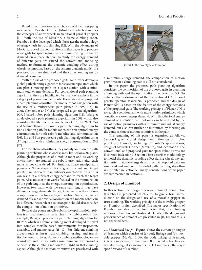
Figure 1 The prototype of Frambot
a minimum energy demand the composition of motionprimitives in a climbing path is still not considered
In this paper the proposed path planning algorithmconsiders the composition of the proposed gaits in planninga moving path and the optimization is achieved by GA Toenhance the performance of the conventional GA a novelgenetic operator Planar-NN is proposed and the design ofPlanar-NN is based on the feature of the energy demandsof the proposed gaits The working principle of Planar-NN isto search a solution path with more motion primitives whichcontribute a lower energy demandWith this the total energydemand of a solution path not only can be reduced by theuse of motion primitives with a minimum individual energydemand but also can further be minimized by focusing onthe composition of motion primitives in the path
The remaining of this paper is organized as followsSection 2 gives a brief design description on our robotprototype Frambot including the robotrsquos specificationsdesign of Movable Gripper (MovGrip) and locomotion Theconventional and proposed gaits for space robotic arms areillustrated in Section 3 Section 4 first describesmethodologyto model the dynamic coupling effect during wheels naviga-tion After that the energy demand of the proposed gaits aresimulated and analyzed The global path planning algorithmis illustrated in Section 5 Finally contributions of this paperare summarized in Section 6
2 Design of Frambot
In this section the design of a novel frame climbing robot(Frambot) is presented which aims to give a brief intro-duction on the design and use of a movable gripper intruss climbingThe working principle of the movable gripperon Frambot is first described The major specifications ofFrambot are also summarized After that the climbingmotions of Frambot are illustrated Details of the design andperformance of Frambot are presented in [11 12] and this isnot repeated here
21 Mechanical Design Figure 1 shows the current prototypeof Frambot which consists of (a) body linkage and (b) mov-able gripper (MovGrip) For the body linkage of Frambotit is a four degree of freedom (DOF) serial robot linkageactuated by digital servomotors Table 1 summaries themajorspecifications of Frambot
Journal of Robotics 3
Table 1 The specifications of frambot
Weight 171 kgDimension (119871119882119867) (725 21 145) cmGripping width (30ndash45) cmMaximum gripping force sim45NSteering angle of wheels 5 degreesDiameter of wheels 2 cmVertical climbing speed 231 cmsHorizontal climbing speed 405 cmsUpside-down climbing speed 62 cms
The structure of MovGrip is composed of two majorparts (a) gripper jaw and (b) parallel gripping mechanism(Figure 2) Different from conventional design each of thegripper jaws is equipped with two wheels actuated by minigeared motors through a spur gears transmission For theparallel gripping mechanism it is actuated by two linearservo motors and the gripping force is generated by thecompression of springs To simplify the design the wheelsrsquotraction of MovGrip is contributed by the gripping force
22 Locomotion on a Truss For the design of conventionalspace manipulators their end effector is mainly designed forgrasping and different locomotion can only be performedby the swing motion of their body linkage With the use ofMovGrip wheels locomotion can be utilized to minimize thearmrsquos swing motion For linear locomotion it is performedby the rotation of wheels in MovGrip and the armrsquos swingmotion in conventional turnaround and inchworm gaits aretherefore eliminated Figures 3 and 4 illustrate the turningand exterior transition of Frambot on a hexagonal aluminumtruss respectively Frambot first lifts up the front gripper byusing the body linkage After that it uses wheels locomotionto move forward until the front gripper can form a graspon the target truss Once a grasp is formed the rear gripperis opened and lifted up Similarly Frambot uses wheelslocomotion to climb forward until there is enough space forit to lower the rear gripper
3 Design of Locomotion
One of the major contributions in this paper is to proposenew gaits for space manipulators with an open chain config-uration For its gripping mechanism it is assumed to be theconcept presented in previous section By this the grippernot only provides a grasp on a truss but also allows a linearlocomotion along the truss by the embedded active wheelsUnder this configuration both conventional and proposedgaits can be realized and compared unbiasedly For simplicitywe focus on the motion of a cubic truss structure which issymmetric about its principal axes With this the moment ofinertia about the three axes is identical which simplifies theenergy demand analysis
31 Joint Configurations Aforementioned a space station isfirst regarded as a cubic truss For the locomotion on a truss
Circuit box
Gripper jaw
Wheel
Battery
Support tail
Figure 2 The design of MovGrip
not all the joints of a seven-DOF space manipulator areinvolved Therefore the body of a space manipulator isdefined as a five-DOF chain-like manipulator with its twoends equipped with MovGrip (Figure 5) It is a Roll-Pitch-Pitch-Pitch-Roll configuration which can be considered as asimplified version of Canadarm 2 and ERA
32 Linear Locomotion For linear locomotion the mostcommonly used gaits are turnaround and inchworm gaits[20] Figure 6 illustrates the turnaround gait and the crossmarked at the upper gripper indicates a closed grip Firstlythe robot forms a grasp on a truss by the upper gripperand the other one is lifted up through the rotation of thethree pitch joints (P2ndashP4) After that the robot arm swingsfrom back to front by using the roll joint (R5) Finally thefree gripper is lowered down and forms a grasp on thetruss The motion continues by repeating the above motionsteps
For inchworm gait it is realized by using the three pitchjoints (Figure 7) Firstly the upper gripper forms a grasp onthe truss and the lower one opens After that the three pitchjoints (P2ndashP4) rotate so that the robot arm folds Then thelower gripper closes and the other one opens Finally thethree pitch joints rotate so that the robot arm unfolds and thefront gripper forms a grasp on the truss
For the proposed locomotion we propose the use ofwheels locomotion to reduce the swing motions of a spacemanipulator Since the manipulator does not move withrespect to the gripper the armrsquos swing motion is eliminatedHence the energy demand is converted to the rotation ofwheels in the grippers
4 Journal of Robotics
(a) (b) (c) (d)
(e) (f) (g) (h)
Figure 3 The turning motion of Frambot
(a) (b) (c)
(d) (e) (f)
Figure 4 The exterior transition of Frambot
33 Turning Figure 8 illustrates the gait for turning Firstlythe robot forms a grip by the front gripper and the other oneis lifted up by the three pitch joints (P2ndashP4) (a) After thatthe robot arm swings clockwise from the back to the left sideby the roll joint (R5)The three pitch joints then rotate whichlowers the free gripper (b) It grips the left truss and the othergripper opens After that the free gripper is lifted by the pitchjoints and the robot arm swings until the free gripper is in
a position above the left truss (c) Finally the free gripper islowered and a closed grasp is formed on the truss (d)
Figure 9 illustrates the proposed turning motion Firstlythe robot forms a grasp by the rear gripper and the other oneis lifted up by the three pitch joints (P2ndashP4) (a) After thatthe robotmoves forward by using wheels locomotion (b)Therobot arm then swings to the left side by the roll joint (R1)Thethree pitch joints rotate which lowers the free gripper (c) It
Journal of Robotics 5
R1
P2
P3
P4
R5
Wheels
P3
Figure 5 The joint configuration of the manipulator
P2
P3
P4
(a)
R5
(b)
P2
P3
P4
(c) (d)
Figure 6 The gait for turn around gait
grips the left truss and the other gripper then opens Afterthat the free gripper is then lifted by the pitch joints andthe robot arm swings until the free gripper is above the lefttruss (d) Finally the robot moves forward by using wheelslocomotion until there is enough space for it to lower the freegripper (e) and (f)
As an alternative of the turning gait space manipulatorscan perform inchworm gait to replace the wheels locomotionin the proposed turning gait Since the notion of inchwormgait is illustrated before the use of inchworm gait in trussturning is not repeated here When compared with theconventional turning gaits there are two common motionsteps which are the target posture of the motion steps (c) and(f) For the proposed turning gait it uses wheels locomotionto reduce the rotation of roll joints in conventional gaits
34 Exterior Transition Figure 10 shows the conventionalgait for exterior transition by using the turnaround gaitFirstly the robot forms a grasp by the upper gripper and theother one is lifted up by the three pitch joints (P2ndashP4) (a)After that the robot arm swings from back to the front bythe roll joint (R5) (b) Then the pitch joints rotate so thatthe free gripper can form a grasp on the exterior of the truss(c) The free gripper closes and the other gripper then opens
(a) (b) (c) (d)
P2
P3
P4 P4
P4
P3
P3
P2P2
Distance
P4
P3
P2
Figure 7 The gait for inchworm gait
Similarly the robot arm swings up by the pitch joints (d)which aims to make the whole robot above the exterior trussAfter that the roll joint (R1) rotates which swings the robotarm forward (e) Finally the free gripper is lowered and aclosed grasp is formed on the truss (f)
Figure 11 shows the proposed gait for exterior transitionFirstly the robot forms a grasp by using the lower gripperand the other one is lifted up by the three pitch joints (P2ndashP4) (a) After that the robot moves forward by using wheelslocomotion (b) Then the pitch joints rotate so that the freegripper can grasp the exterior of the truss (c)The free grippercloses and the other gripper then opens Similarly the robotarm swings up by the pitch joints (d) which aims to make thewhole robot above the exterior truss Finally the robot movesforward by using wheels locomotion until there is enoughspace for it to lower the free gripper (e) and (f)
Similar to the turning gait space manipulators can alsoperform inchworm gait to replace the wheels locomotion inthe proposed transition gait and it is not illustrated here Alsothere are two commonmotion steps for the conventional andproposed transition gaits which are the target posture of themotion steps (Figures 11(c) and 11(f)) For the proposed gaitit minimizes the rotation of roll joints by driving the robotforward using wheels locomotion
4 Analysis of Energy Demand
For the energy demand of a gait it is defined as the energyrequired to perform that gait For the jointrsquos motion theenergy demand ldquo119864
119894rdquo of the 119894th joint can be formulated as
the time integration of the joint torque ldquo120591119894(119905)rdquo and angular
velocity ldquo 119902119894(119905)rdquo multiplication as
119864119894= int 120591119894(119905) sdot 119902119894(119905) 119889119905 (1)
Similarly the energy demand ldquo(1198641015840119894)rdquo for the wheels
locomotion is the time integration of the wheels tractionforce ldquo119865
119894(119905)rdquo and linear velocity ldquo119881
119866(119905)rdquo multiplication as
1198641015840
119894= int119865119894(119905) sdot 119881
119866(119905) 119889119905 (2)
The total energy demand of a gait can be computed asthe sum of all individual energy demands To compare the
6 Journal of Robotics
P2
P3
P4
P2
P4
(a)
R5R5
(b)
R1R1
(c)
P2 P3 P4P2 P3 P4
(d)
Figure 8 The conventional gait for turning
energy demand of different gaits of a space manipulator thekinematics momentums and dynamics of a space roboticsystem provide the fundamental approach Because of thisthis section first presents the modeling of a space roboticsystem After that the energy demand of different gaits isanalyzed
41 Modeling of a Space Robotic System Since the formula-tion of the dynamic coupling effect of a space manipulatorwith one end fixed on a space station is commonly established[21ndash23] this paper only focuses on the approach tomodel thedynamic coupling effects underwheels locomotionA generalmodel for a space robotic system is first described Afterthat the systemrsquos kinematics and momentum relationshipsare presented To determine the systemrsquos dynamic equationsLagrangian formulation is utilized
Figure 12 shows a general model of a space roboticsystem The space manipulator consists of 119899 joints which arenumbered from 1 to 119899 Since the manipulator is mounted ona free floating space station the whole system is regarded asa free flying chain-like system with 119899 + 1 links As the spacestation can translate and rotate freely about the inertial frameaxes the total DOF of the system is 119899 + 6
For the systemmodeling three coordinate frames are firstintroduced which include (a) inertial frame (b) manipulator
frame and (c) base frame For the inertial frame its origin isfixed in the space For the manipulator frame and base frametheir origins are located at themass center of themanipulatorand base respectively During the modeling a number ofnotations are defined as follows
119902 isin 119877119899 joint variable vector (= [119902
1 1199021 119902
119899]119879)
119902 isin 119877119899 joint angular velocity vector
120591 isin 119877119899 joint torque vector (= [120591
1 1205911 120591
119899]119879)
119877119887isin 1198773 position vector of the base
119877119894isin 1198773 position vector of the mass center of link 119894
119877119866isin 1198773 position vector of the manipulatorrsquos mass
center center
119877119894119887isin 1198773 position vector of the link 119894wrt to the base
frame
119877119866119887
isin 1198773 position vector of the manipulatorrsquos mass
center 119894 with respect to the base frame
119881119887isin 1198773 linear velocity of the base
Ω119887isin 1198773 angular velocity of the base
119898119887 mass of the base
Journal of Robotics 7
P4
P3
P2
(a) (b)
R1
(c)
R5
(d) (e)
P2 P3 P4
(f)
Figure 9 The proposed turning motion
119898119879 total mass of the system
119898119866 total mass of the manipulator
119868119866isin 1198773 times 3 inertial tensor matrix of the manipulator
with respect to its mass center
119868119887isin 1198773 times 3 inertial tensor matrix of the base with
respect to its mass center
119880 isin 1198773 times 3 3 times 3 identity matrix
All vectors are described with respect to the inertial coor-dinate system unless another coordinate system is mentioned
and 119894 = 0 1 119899 Here two matrix functions are defined fora vector 119903 = [119903
119909 119903119910 119903119911]119879 as follows
[119903times] equiv [
[
0 minus119903119911119903119910
119903119911
0 minus119903119909
minus119903119910119903119909
0
]
]
[119866 (119903)] equiv [119903times]119879
[119903times]
=[[
[
1199032
119910+ 1199032
119911minus119903119909119903119910
minus119903119909119903119911
minus1199031199091199031199101199032
119909+ 1199032
119911minus119903119910119903119911
minus119903119909119903119911
minus1199031199101199031199111199032
119909+ 1199032
119910
]]
]
(3)
In addition several assumptions are made First of allall links are rigid bodies and there are no external forces
8 Journal of Robotics
P2
P4
P3
(a)
R5
(b)
P2
P4
P3
(c)
P2P3
P4
(d)
R1
Side view
(e)
P2P4
P3
(f)
Figure 10 The conventional gait for exterior transition
P3
P4
P2
(a) (b)
P2
P3
P4
(c)
P2
P3 P4
(d) (e)
P3P2
P4
(f)
Figure 11 The proposed gait for exterior transition
and torques acting on the system As a result the totalpotential energy of the system is equal to zero Duringwheels locomotion it is assumed that the configuration ofthe manipulator is maintained (ie 119902 = 119902 = 0) Also themodeling is with respect to the inertial frame unless othercoordinate frame is specified
42 Kinematics To model the kinematics of the system themanipulator is first visualized as a prismatic joint and the
Space station
Figure 12 A general model of a space robotic system
closed MovGrip is the gripping point on the base Duringwheels locomotion the resultant wheels traction becomes thepushing force of the prismatic joint acting on the base and thegripping point is moving together with wheels locomotionSince the manipulator does not move with respect to thegripper the position vector of the manipulatorrsquos mass centercan be formulated as follows
119877119866= 119877119887+ 119877119866119887 (4)
By taking time derivative on both sides we can derive thesystemrsquos kinematics relationship as follows
119881119866= 119881119887+ Ω119887times 119877119866119887
+ 119907119866 (5)
where 119907119866is the linear velocity of the manipulator under
wheels locomotion 119881119866is the linear velocity of the manipula-
torrsquos mass center with respect to the inertial frame Since thewhole system rotates together underwheels locomotion boththemanipulator and base have the same angular velocity (ieΩ119866= Ω119887)
43 Linear and Angular Momentums Aforementioned it isassumed that there are no external forces and torques actingon the system and the linear and angular momentums of thesystem are conserved as
119875 = 119898119887119881119887+ 119898119866119881119866
119871 =119861
119868119887Ω119887+ 119898119887119877119887times 119881119887+119861
119868119866Ω119887+ 119898119866119877119866times 119881119866
(6)
From the kinematics relationship we express the vari-ables 119877
119866and 119881
119866in terms of 119881
119887 Ω119887and 119907
119866 By rearranging
the variables of themomentum equations they can derive thefollowing momentum relationship
[119875
119871] = [
119872119881119887
119872119881119887Ω119887
119872119879
119881119887Ω119887
119872Ω119887
] [119881119887
Ω119887
] + [119872119881119887119907119866
119872Ω119887119907119866
] 119907119866 (7)
Journal of Robotics 9
where
(i) 119872119881119887equiv Σ119899
119894=0119898119894119880 = 119898
119879119880 isin 119877
3 times 3
(ii) 119872119881119887Ω119887
equiv 119898119866[119877119866119887times] isin 119877
3 times 3
(iii) 119872Ω119887equiv 119868119866+ 119898119866[119866(119877119866119887)] + 119868
119887isin 1198773 times 3
(iv) 119872119881119887119907119866
equiv 119898119866119869119898119879119866
isin 1198773 times 1
(v) 119872Ω119887119907119866
equiv 119898119866[119877119866119887times]119869119898119879119866
isin 1198773 times 1
119869119898119879119866
is the linear Jacobian matrix of the manipulatorunder wheels locomotion and is defined as follows
119869119898119879119866
=119868Rot119866119911119866 (8)
119868Rot119866is the rotation matrix from the manipulator frame
to the inertial frame and 119911119866is the 119911-axis of the manipulator
frame which indicates the direction of gripperrsquos movement Ifthe system is initially at rest the following constraints can beobtained
[119872119881119887
119872119881119887Ω119887
119872119879
119881119887Ω119887
119872Ω119887
] [119881119887
Ω119887
] + [119872119881119887119907119866
119872Ω119887119907119866
] 119907119866= [
0
0] (9)
44 Dynamics For the systemrsquos dynamic modeling theconventional Lagrangian approach is utilized Since the totalpotential energy of the system is zero the total energy of thesystem during wheels locomotion is the sum of translationaland rotational kinetic energy (119870) of all bodies in the systemas
119870 equiv1
2(119898119887119881119879
119887119881119887+ Ω119879
119887119868119887Ω119887+ 119898119866119881119879
119866119881119866+ Ω119879
119887119868119866Ω119887) (10)
Similar to the momentum equations the energy equa-tions can be expressed in terms of 119881
119887 Ω119887 and 119907
119866as
119870 =1
2
120579119879
119872(120579) 120579
119872 (120579) =[[
[
119872119881119887
119872119881119887Ω119887
119872119881119887119907119866
119872119879
119881119887Ω119887
119872Ω119887
119872Ω119887119907119866
119872119879
119881119887119907119866
119872119879
Ω119887119907119866
119872119907119866
]]
]
isin 1198777 times 7
120579119879
= [119881119887Ω119887119907119866]
119872119907119866= 119898119866119869119879
119898119879119866
119869119898119879119866
isin 1198771 times 1
(11)
The matrix 119872(120579) is the system inertial matrix which ispositive definite and symmetric By using the Lagrangianformulation
119889
119889119905(120597119870
120597 120579
) minus120597119870
120597120579= 120591 (12)
the dynamic model of the system can be derived as
119872(120579) 120579 + 119862 (120579 120579) 120579 = 120591 (13)
where 120591 is the generalized force vector and119862(120579 120579) is the non-linear centrifugal and Coriolis forces as
119862 (120579 120579) 120579 = (120579) minus120597
120597120579(1
2
120579119879
119872(120579) 120579) (14)
Table 2 The system parameters for simulations
1198970
05m 119868119887119909119909 119868119887119910119910 119868119887119911119911
13599 kgm2
1198971
05m (1198681119909119909 1198681119910119910 1198681119911119911) (13 13 01) sdot 10
minus4 kgm2
1198972
2m (1198682119909119909 1198682119910119910 1198682119911119911) (04 802 802) sdot 10
minus4 kgm2
1198973
2m (1198683119909119909 1198683119910119910 1198683119911119911) (04 802 802) sdot 10
minus4 kgm2
1198974
05m (1198684119909119909 1198684119910119910 1198684119911119911) (13 01 13) sdot 10
minus4 kgm2
1198975
05m (1198685119909119909 1198685119910119910 1198685119911119911) (13 13 01) sdot 10
minus4 kgm2
119898119887
4837 kg 1198981
15 kg1198982
10 kg 1198983
10 kg1198984
10 kg 1198985
15 kg
45 Simulation Study For the analysis of energy demand ofthe proposed gaits it is assumed that there are no externalforces and torques acting on the system For the space stationit is assumed to be a cubic truss structure which gives asymmetric property for simulations Length of a side of thetruss is 10 meters and the presented system dynamic model isutilized to compute the energy demand
Both the proposed and conventional gaits are simulatedand three different aspects are studied including (a) linearlocomotion (b) turning and (c) exterior transition For eachof the three aspects three gaits are considered including(a) turnaround gait (b) inchworm gait and (c) wheelslocomotion For fair comparison the moving distance ofdifferent gaits in each of the three aspects is equal Also thetime to perform different gaits in each of the three cases isfixed Table 2 lists the system parameters for simulations
Figure 13 shows the definition of the base base frame androbot initial and final configurations For linear locomotionthe robot (marked with dotted line) is initially set at thecorner of the edge A It moves forward by using different gaitsand stops at a distance of 2 meters away from the other end(corner G)
For the turning gaits at a truss corner only the turn leftgait is discussed and it is performed from edge A to edge Bof the space station in Figure 13 The robot is initially set ata position where its front gripper (119891) is at a distance of 2828meters on edgeA away fromcornerG It performs the turningmotion by using different gaits and stops at a position on edgeB where its rear gripper (119903) is at a distance of 6828 metersaway from that corner For the exterior transition at a trusscorner the motions are performed from edge A to edge Cof the space station in Figure 13 The robot is initial set at aposition where its front gripper (119891) is at a distance of 2meterson edgeA away from cornerG It performs exterior transitionand stops at a position on edge C where its rear gripper (119903) isat a distance of 6 meters away from that corner
Figures 14 and 15 show the angular displacement andtorque profile of the inchworm gait respectively Since thedistance travel of an inchworm gait is two meters the tworepeated patterns in Figure 14 indicate the two repetitionsof the arm folding and unfolding motions Also only thethree pitch joints (joints 2ndash4) are involved to perform theinchworm gait Therefore the torque profile of three pitchjoints is nonzero
10 Journal of Robotics
2 mFinal position
Initial position
B
G
A
C
Figure 13 The space station base frame and robot initial and finalconfiguration for wheels locomotion
0 50 100 150 200 250 300 350 400
0
50
100
Time (s)
Join
ts an
gle (
deg)
Joint 1Joint 2Joint 3
Joint 4Joint 5
minus150
minus100
minus50
Figure 14 The jointsrsquo displacement profiles for the inchworm gait
By using (1) the total energy demand of the inchwormgait is 20458 joules per meter (Jm) By using the similarapproach the total energy demand for the other turning andtransition motions can be computed which are summarizedin Table 3
From the nature of the gaits the arm folding and unfold-ing motions of the inchworm gait on the one hand requirethe largest joints movement when compared with the othersOn the other hand the distance travel in one motion step isthe smallest Given a certain operation time to complete thegait the jointsrsquo torque and angular velocity are much larger
0 50 100 150 200 250 300 350 400
0
5
10
15
Time (s)
Join
ts to
rque
(N)
Joint 1Joint 2Joint 3
Joint 4Joint 5
minus5
minus10
minus15
Figure 15 The jointsrsquo torque profiles for the inchworm gait
Table 3 The total energy demand of different gaits
Inchworm Turn around Wheelslocomotion
Linear 20458 Jm 10097 Jm 00424 JmTurning 412473 J 46744 J 31689 JExteriortransition 173267 J 93039 J 37817 J
than the others Under a constraint on the operation time theinchworm gait is regarded as a high power demand motion
For the wheels locomotion the wheelsrsquo traction force isin the same direction as the movement Also all the mass ismoving along a straight line during wheels locomotionWitha long limb design of conventional space manipulator theuse of wheels locomotion can avoid the armrsquos swing motionwhose joints torque is high Therefore the use of wheelslocomotion to reduce the joints movement allows an energyefficiency locomotion on a space station
5 Global Path Planning Algorithm
For the proposedminimumenergy demand-based path plan-ning algorithm the optimization goal is first defined Giventhe robotrsquos initial position and orientation a list of checkpoints (including the target point) and their position withrespect to an inertial frame the objective is to search a pathwhich passes all the check points once and reaches the targetpoint with aminimumenergy demandThis can be visualizedas a space manipulator is commanded to follow the solutionpath and visit a list of points for monitoring or maintenancetasks on a space station Finally it is commanded to reach atarget point for charging or standby
Figure 16 shows the geometry of a space stationThe edgesin the structure are the frame for grasping and the corners are
Journal of Robotics 11
0
20
40
0
20
400
10
20
30
40
Figure 16 The geometry of a space station
Normalvector
Head vector
Check point
D
A
B
C
E
F
Inertial frame
Figure 17 An example illustrating the computation of individualdemand
the possible check points To travel all the check points alongthe solution path a space manipulator is assumed to performthe basic motion primitives
51 Representation of a Chromosome In conventional GA achromosome is the basic element for genetic evolution Forthe proposed algorithm a chromosome represents the pathfor navigation It is composed of 119899 genes and 119899 is equal to thetotal number of check points Each of the genes is labeledwitha unique integer which indicates the visiting orderThereforethe integers in a chromosome describe the order of checkpoints being visited
52 Evaluation Function In GA chromosomes with a higherfitness (lower energy demand) with respect to the optimiza-tion goal are selected for genetic evolution To measure
the fitness of a chromosome an evaluation function shouldbe defined In this algorithm the optimization goal is tosearch an optimal path with a minimum energy demandThe fitness function is therefore defined as the total energydemand of the path Since a chromosome is composed ofgenes representing the order of check points being visitedthe total energy demand of a path is the summation of theindividual energy demand of all consecutive gene pairs alongthe chromosome Figure 17 shows a manipulator climbingon a truss structure as an example It is currently at thecheck point 119894 minus 1 and gripping on the edge A To computethe energy demand for reaching the next check point thecurrent manipulatorrsquos orientation is considered To representthe manipulatorrsquos orientation two vectors are defined Theyare the head and normal vectors which are labeled withorange and red colors respectively For the head vector itindicates the current gripper direction after traveling fromthe point 119894 minus 2 to 119894 minus 1 If 119894 minus 2 is the first point it representsthe initial orientation of the robot gripper For the normalvector it is perpendicular to the truss surface and pointingaway from the robot gripper
For the energy demand of a pair of check points there arethree major possible cases The first one is the case when theline connecting them is parallel to one of the inertial frameaxesThe points pair 119894minus1 and 119894 in Figure 17 shows an examplewith the line jointing them is parallel to the 119911-axis For thesecond case two check points lie on a plane which is parallelto the plane formed by any two of the inertial frame axesThepoints pair 119894 minus 1 and 119894 + 1 shows an example with the planeparallel to the 119909-119911 plane of the inertial frame For the last casethe coordinate values of the two check points are differentThe points pair 119894 minus 1 and 119894 + 2 shows an example that doesnot satisfy the first two cases For simplicity this paper onlyillustrates the computation of individual energy demand of apoints pair in the second case Because a similar techniquecan be used for the other cases it is not repeated here
Assumed that the manipulator is currently at the checkpoint 119894 minus 1 and gripping on the edge E in this case ifits head and normal vectors are initially pointing to thenegative 119910-axis and positive 119911-axis respectively there are twopossible paths to travel from point 119894 minus 1 to 119894 + 1 The firstmotion sequence contains interior transition linear frameclimbing turn left and linear frame climbing The othermotion sequence contains turn left linear frame climbinginterior transition and linear frame climbing Since theenergy demand of both paths is the same the motionsequencing to travel from point 119894 minus 1 to 119894 + 1 is chosenrandomly in order to maintain the global search of a solutionpath in GA The corresponding energy demand is computedas follows
119864119894minus1= 119864interior + 119864left + (Δ119911 + Δ119909) times 119864linear (15)
Δ119909 and Δ119911 are the edge length between the two pointsalong the 119909 and 119911 axes of the inertial frame respectively119864linear 119864left and 119864interior are the energy demand for themanipulator to move one meter forward turn left andperform interior transition respectively After computing themove to the next check point the updated head and normal
12 Journal of Robotics
vectors of the manipulator become the current head andnormal vectors Although there are other possible cases forthe initial condition of the manipulator in all the above threecases similar techniques can be utilized and they are notrepeated here for simplicity Finally the total energy demandto travel along a solution path is the sum of all individualenergy demands and it is formulated as follows
119864Total =119899minus1
sum
119894=1
119864119894 (16)
119864119894is the energy demand for a manipulator to navigate
from the 119894th check point back to the 119894 + 1th point
53 Genetic Operators From the energy demands of themotion primitives in Table 3 the total energy demand ofa path is lower if it is composed of more planar (orlinear) path segments Because of this the proposed pathplanning algorithm focuses on the searching of an optimalpath which consists of more planar path segments Withthe use of GA for optimization we enhance the evolutionprocess by developing a novel exchange mechanism forthe genetic information of a chromosome It is a geneticoperator which promotes the path with planar (or linear)genes segments It is called Planar-NN andNNmeans nearestneighbor
Figure 18 illustrates the working principle of Planar-NNA sample frame structure is shown and the orange dotindicates the initial position of the manipulator The greyand blue dots are the intermediate and final check pointsrespectively An elitist chromosome for genetic evolutionusing Planar-NN is first selected as below Starting from thehead gene (gene with an index 1) the operator searches thefollowing genes if the genes pair satisfies one of the followingcases
(i) The genes pair forms a line which is parallel to one ofthe inertial frame axes
(ii) The genes pair forms a plane which is parallel to theplane formed by any two of the inertial frame axes
From Figure 18 the gene with an index 2 is the firstobserved gene which satisfies the first conditionTherefore itis extracted and adjoined to the current gene After that theextracted gene becomes the current gene and the selectionprocess is repeated until there is no genes left for extractionIf there is no genes matching the above conditions the firstunselected gene which follows the current gene is extractedFrom the remaining genes the second extracted gene is theone with an index 3 since the points pair with gene indexes2 and 3 satisfies the second condition By repeating thethe extraction and adjoining processes the final offspring isobtained
The design of Planar-NN is a greedy search for an optimalsolution To avoid a local optimal solution three conventionalgenetic operators are involved in the evolution process Theyare (a) genes flip (b) genes swap and (c) genes slide Forthe working principle of these conventional operators it isillustrated in [24] and it is not repeated here
1 3 2 5 4 6
1
1 2 3 4 5 6
3 2 5 4 6
1 2 3 5 4 6
1 2 3 5 4 6
1 2 3 4 5 6
Before
1 2
3
4
5
6
Offspring
Figure 18 The idea of the proposed operator Planar-NN
Table 4 The key parameters for the simulations
Robot initial position (4 29 4)Robot initial head vector (1 0 0)Robot initial normal vector (0 0 1)Robot final position (31 26 25)Maximum number of generation 1000Number of experiments 5
54 Simulation Study and Discussion In this section theperformance of the proposed algorithm is evaluated bysimulating a path planning problem on a structural frameTo evaluate the algorithm under different aspects differentsimulations are performed Forty points are first randomlygenerated on a cubic frame structure and the edge length is 40meters It is divided into many smaller cells each with 1 meterlong (0 le 119909 119910 119911 le 40) The genetic operators involved in theevolution process are (a) genes flip (b) genes swap (c) genesslide and (d) Planar-NN The probabilities of selecting themare equal during the evolution process and the maximumnumber of generation is 1000 Table 4 lists some of the keyparameters for the simulations
The first simulation aims to show the effect of differentpopulation sizes on the final solution path The conventional
Journal of Robotics 13
Table 5 A comparison of convergent rate in the first 400 generations
Fitness at 119899 th generation0 th 100 th 200 th 300 th 400 th
Conventional 31478 25457 24146 23754 23442Proposed 31478 23749 23523 23255 22947
20 30 40 50 60 70 80 90 100222
224
226
228
230
232
234
236
Population size
The t
otal
ener
gy d
eman
d (J
)
Flip + swap + slide
Figure 19 The total energy demand of the final solution withdifferent population sizes
genetic operators are utilized during the genetic evolution Atthe same time the maximum population size is varied Thesimulation is repeated five times and the mean total energydemand of the best solution path is shown in Figure 19
In general the total energy demand of the best solu-tion path searched by the algorithm decreases when thepopulation size increases It is reasonable because morechromosomes are involved in searching the global optimalpath From the simulation results the best population size isselected as 80
In the second simulation the proposed genetic operatorPlanar-NN is utilized to search a solution path and the resultis compared with the results of using conventional geneticoperators The simulation is repeated 10 times and the meanof the ten simulation results is shown in Figure 20
From Figure 20 the overall convergent rate is signif-icantly enhanced when the proposed genetic operator isinvolved in the evolution process Also the proposed algo-rithm can search a solution path with a lower total energydemand Table 5 gives a comparison of the convergent ratebetween the use of conventional operators alone and thehybrid use of conventional operators and Planar-NN
When Plannar-NN is involved for genetic evolution thetotal energy demand of a path represented by the currentbest chromosome is decreased below 255 joule in the first100 generation Also the evolution process keeps improvingthe fitness of the current fittest chromosome and the resultis closed to the optimal solution after 400 generations with
0 200 400 600 800 1000220
230
240
250
260
270
280
290
300
310
320
The t
otal
ener
gy d
eman
d (J
)
Flip + swap + slide + planar-NNFlip + swap + slide
Figure 20 The effect of different genetic operators on the best pathgiven by the proposed algorithm
a variation within 11 joule To save the computation timethe evolution process can be terminated if the total energydemand of the current best path is satisfied
To explain these the nature of the Planar-NN and thehybrid use of genetic operators are considered The designof Planar-NN is a greedy local search It groups the geneswith a planar or linear relationships Therefore the useof Planar-NN can result in a solution path with segmentsof planar or linear check points Also the hybrid use ofconventional genetic operators can maintain the conceptsof natural evolution in GA and so local optimums can beavoided Hence the proposed algorithm can facilitate thesearch of a minimum energy demand path Also it verifiesthat the composition of motion primitives in a motion pathis also important in energy demand minimization Based onthe simulation results the total energy demand of the bestsolution path given by the proposed algorithm is 21879 jouleand the corresponding solution path is displayed in Figure 21The green lines represent the edge of the frame structure andthe blue points indicate the randomly generated check pointsThe initial and final robot positions are marked with blackand pink dots respectively
6 Conclusion and Future Work
In this paper we propose the design of new gaits for spacemanipulators with a lower energy demand which is themajor
14 Journal of Robotics
0
20
40
0
20
400
10
20
30
40
Figure 21 The best path given by the proposed algorithm
contribution of this research Based on the system dynamicmodel different gaits are simulated and the correspondingenergy demand is analyzed Results show that the proposedgaits require a lower energy demand when compared withconventional gaits With the use of the proposed gaits aminimum energy demand-based path planning algorithm isalso developed Different from traditional approaches theproposed algorithm considers the composition of motionprimitives in a path for the energy demand minimizationBased on the framework of conventional GA we adoptedthe concept of genetic modification to design a new geneticoperator Planar-NN Based on the simulation results itbenefits the final solution in terms of fast convergent rate andlower energy demand Also it verifies that the compositionof motion primitives in a path is also important in energydemand minimization Although this paper assumes a spacestation as a cubic truss structure which is different fromthe existing space station such as International Space Station(ISS) the geometry of the cubic truss can be modified andthe concept of nonfeasible edges can be introduced by highlyincreasing the energy demand of those edges For the futuredevelopment the proposed algorithm will be able to handleuncertainties such as infeasible path and obstacle avoidance
References
[1] P Acquatella ldquoDevelopment of automation amp robotics in spaceexplorationrdquo Journal of Robotics and Autonomous Systems vol10 no 106 2008
[2] MacDonald Dettwiler Space and Advanced Robotics ldquoCa-nadarmmdashthe SRMS technical detailsrdquo httpwwwieeecamillenniumcanadarmcanadarm technicalhtml
[3] C Sallaberger ldquoCanadian space robotic activitiesrdquo Acta Astro-nautica vol 41 no 4ndash10 pp 239ndash246 1997
[4] K Yoshida ldquoETS-VII flight experiments for space robot dynam-ics and control-theories on laboratory test beds ten years agonow in orbitrdquo in Experimental Robotics VII LNCIS D Rus andS Singh Eds pp 209ndash218 Springer Berlin Germany 2001
[5] N Sato and Y Wakabayashi ldquoJEMRMS design features andtopics from testingrdquo in Proceedings of the 6th InternationalSymposium on Artificial Intelligence and Robotics amp Automationin Space (i-SAIRAS rsquo01) Canadian Space Agency St-HubertQuebec Canada 2001
[6] R Boumans and C Heemskerk ldquoThe European Robotic Armfor the International Space Stationrdquo Robotics and AutonomousSystems vol 23 no 1-2 pp 17ndash27 1998
[7] A Kauderer ldquoNASAmdashCanadarm2 and the Mobile Servic-ing Systemrdquo httpwwwnasagovmission pagesstationstruc-tureelementsmsshtml
[8] M Vona C Detweiler and D Rus ldquoShady robust trussclimbing with mechanical compliancesrdquo in Proceedings of theInternational Symposium on Experimental Robotics 2006
[9] Y Yoon and D Rus ldquoShady3D a robot that climbs 3D trussesrdquoin Proceedings of IEEE International Conference on Robotics andAutomation (ICRA rsquo07) pp 4071ndash4076 April 2007
[10] M Bonani S Magnenat P Retornaz and F Mondada ldquoThehandbot a robot design for simultaneous climbing and manip-ulationrdquo in Proceedings of the 2nd International Conference onIntelligent Robotics and Applications pp 11ndash22 2009
[11] W K Chung J Li Y Chen and Y Xu ldquoA novel designof movable gripper for non-enclosable truss climbingrdquo inProceedings of IEEE International Conference on Robotics andAutomation Shanghai China May 2011
[12] W K Chung and Y Xu ldquoA novel frame climbing robotframbotrdquo in Proceedings of IEEE International Conference onRobotics and Biomimetics pp 2559ndash2566 Phuket Thailand2011
[13] J A Fernandez J Gonzalez L Mandow and J L Perez-de-la-Cruz ldquoMobile robot path planning a multicriteria approachrdquoEngineering Applications of Artificial Intelligence vol 12 no 4pp 543ndash554 1999
[14] M Gemeinder and M Gerke ldquoGA-based search for paths withminimum energy consumption for mobile robot systemsrdquo inProceedings of IEEE International Conference on 7th Fuzzy Dayson Computational Intelligence Theory and Applications vol2206 pp 599ndash607 2001
[15] T Wang B Wang H Wei Y Cao M Wang and Z ShaoldquoStaying-alive and energy-efficient path planning for mobilerobotsrdquo in Proceedings of IEEE International Conference onAmerican Control Conference pp 868ndash873 June 2008
[16] C COoi andC Schindelhauer ldquoMinimal energy path planningfor wireless robotsrdquo Mobile Networks and Applications vol 14no 3 pp 309ndash321 2009
[17] S Liu and D Sun ldquoOptimal motion planning of a mobile robotwith minimum energy consumptionrdquo in Proceedings of IEEEInternational Conference on Advanced Intelligent Mechatronics(AIM rsquo11) pp 43ndash48 2011
[18] C Balaguer A Gimenez J M Pastor V M Padron andM Abderrahim ldquoClimbing autonomous robot for inspectionapplications in 3D complex environmentsrdquoRobotica vol 18 no3 pp 287ndash297 2000
[19] C Balaguer V M Padron A Gimenez J M Pastor and MAbderrahim ldquoPath planning strategy of autonomous climbingrobot for inspection applications in constructionrdquo in Proceed-ings of the International Symposium on Automation amp Roboticsin Construction pp 347ndash352 1999
Journal of Robotics 15
[20] Y Guan L Jiang X Zhang and H Zhang ldquoClimbing gaits ofa modular biped climbing robotrdquo in Proceedings of IEEEASMEInternational Conference on Advanced Intelligent Mechatronics(AIM rsquo09) pp 532ndash537 July 2009
[21] Y Xu Space Robotics Dynamics and Control Kluwer AcademicPublishers 1992
[22] Y Xu ldquoMeasure of dynamic coupling of space robot systemsrdquoin Proceedings of IEEE International Conference on Robotics andAutomation pp 615ndash620 May 1993
[23] M Shibli ldquoUnifiedmodeling approach of kinematics dynamicsand control of a free-flying space robot interacting with a targetsatelliterdquo Journal of Intelligent Control and Automation vol 2pp 8ndash23 2011
[24] W K Chung and Y Xu ldquoA generalized 3-D path planningmethod for robots using Genetic Algorithm with an adaptiveevolution processrdquo in Proceedings of the 8th World Congress onIntelligent Control and Automation (WCICA rsquo10) pp 1354ndash1360Jinan China July 2010
International Journal of
AerospaceEngineeringHindawi Publishing Corporationhttpwwwhindawicom Volume 2014
RoboticsJournal of
Hindawi Publishing Corporationhttpwwwhindawicom Volume 2014
Hindawi Publishing Corporationhttpwwwhindawicom Volume 2014
Active and Passive Electronic Components
Control Scienceand Engineering
Journal of
Hindawi Publishing Corporationhttpwwwhindawicom Volume 2014
International Journal of
RotatingMachinery
Hindawi Publishing Corporationhttpwwwhindawicom Volume 2014
Hindawi Publishing Corporation httpwwwhindawicom
Journal ofEngineeringVolume 2014
Submit your manuscripts athttpwwwhindawicom
VLSI Design
Hindawi Publishing Corporationhttpwwwhindawicom Volume 2014
Hindawi Publishing Corporationhttpwwwhindawicom Volume 2014
Shock and Vibration
Hindawi Publishing Corporationhttpwwwhindawicom Volume 2014
Civil EngineeringAdvances in
Acoustics and VibrationAdvances in
Hindawi Publishing Corporationhttpwwwhindawicom Volume 2014
Hindawi Publishing Corporationhttpwwwhindawicom Volume 2014
Electrical and Computer Engineering
Journal of
Advances inOptoElectronics
Hindawi Publishing Corporation httpwwwhindawicom
Volume 2014
The Scientific World JournalHindawi Publishing Corporation httpwwwhindawicom Volume 2014
SensorsJournal of
Hindawi Publishing Corporationhttpwwwhindawicom Volume 2014
Modelling amp Simulation in EngineeringHindawi Publishing Corporation httpwwwhindawicom Volume 2014
Hindawi Publishing Corporationhttpwwwhindawicom Volume 2014
Chemical EngineeringInternational Journal of Antennas and
Propagation
International Journal of
Hindawi Publishing Corporationhttpwwwhindawicom Volume 2014
Hindawi Publishing Corporationhttpwwwhindawicom Volume 2014
Navigation and Observation
International Journal of
Hindawi Publishing Corporationhttpwwwhindawicom Volume 2014
DistributedSensor Networks
International Journal of
2 Journal of Robotics
Based on our previous research we developed a grippingmechanism Movable Gripper (MovGrip) which combinesthe concepts of active wheels in traditional parallel grippers[11] With the use of MovGrip a frame climbing robotFrambot is also developedwhich illustrates themethodologyof using wheels in truss climbing [12] With the advantages ofMovGrip one of the contributions in this paper is to proposenovel gaits for space manipulators in minimizing the energydemand on a space station To study the energy demandof different gaits we extend the conventional modelingmethod to formulate the dynamic coupling effect duringwheels locomotion Based on the systemrsquos dynamicmodel theproposed gaits are simulated and the corresponding energydemand is analyzed
With the use of the proposed gaits we further develop aglobal path planning algorithm for spacemanipulators whichcan plan a moving path on a space station with a mini-mum total energy demand For conventional path planningalgorithms they are highlighted by many researchers in thecategory of planar mobile robots Fernandez et al proposeda path planning algorithm for mobile robot navigation withthe use of a multicriteria path planar in 1999 [13] In2001 Gemeinder and Gerke proposed a genetic-algorithm-(GA-) based robot path planning algorithm [14] Wang etal developed a path planning algorithm in 2008 which alsoconsiders the lifetime of a mobile robot [15] In 2009 Ooiand Schindelhauer proposed a path planning algorithm tofind a solution path for mobile robots with an optimal energyconsumption for both robotrsquos mobility and communication[16] Liu and Sun proposed a path planning algorithm using119860lowast algorithm with a minimum energy consumption in 2011
[17]For the above algorithms they mainly focus on the path
planning problemswhoseworkspace is limited on a 2DplaneAlthough the properties of a mobile robot and its workingenvironment are studied the robotrsquos orientation after eachmove is not considered For instance space manipulatorspossess a 3D workspace For a given current and targetpoints pair different manipulatorrsquos orientations on a trusscan result in a different energy demand to reach the targetpoint Also most of their works focused on the minimizationof the path length as the energy consumption optimizationHowever two paths with the same path length may havedifferent energy demands In fact it depends on the motionscomposition in reaching a target position Since the energydemand of each individual locomotion of a mobile robot canbe different the search of a solution path should also considerthe composition of motion primitives
Besides the planar mobile robots the optimization prob-lem is also addressed by researchers in climbing robots Forexample Balaguer proposed a path planning algorithm forROMA which is a frame climbing robot developed to travelinto complex metallic-based environments for inspectionassembly and maintenance [18 19] For different climbingaspects such as linear truss climbing turning and transi-tion between surfaces different climbing methodologies areconsidered and the one with a minimum energy demand isselected as the climbing motion for ROMA in that climbingaspect Although the motion primitives are preselected with
Figure 1 The prototype of Frambot
a minimum energy demand the composition of motionprimitives in a climbing path is still not considered
In this paper the proposed path planning algorithmconsiders the composition of the proposed gaits in planninga moving path and the optimization is achieved by GA Toenhance the performance of the conventional GA a novelgenetic operator Planar-NN is proposed and the design ofPlanar-NN is based on the feature of the energy demandsof the proposed gaits The working principle of Planar-NN isto search a solution path with more motion primitives whichcontribute a lower energy demandWith this the total energydemand of a solution path not only can be reduced by theuse of motion primitives with a minimum individual energydemand but also can further be minimized by focusing onthe composition of motion primitives in the path
The remaining of this paper is organized as followsSection 2 gives a brief design description on our robotprototype Frambot including the robotrsquos specificationsdesign of Movable Gripper (MovGrip) and locomotion Theconventional and proposed gaits for space robotic arms areillustrated in Section 3 Section 4 first describesmethodologyto model the dynamic coupling effect during wheels naviga-tion After that the energy demand of the proposed gaits aresimulated and analyzed The global path planning algorithmis illustrated in Section 5 Finally contributions of this paperare summarized in Section 6
2 Design of Frambot
In this section the design of a novel frame climbing robot(Frambot) is presented which aims to give a brief intro-duction on the design and use of a movable gripper intruss climbingThe working principle of the movable gripperon Frambot is first described The major specifications ofFrambot are also summarized After that the climbingmotions of Frambot are illustrated Details of the design andperformance of Frambot are presented in [11 12] and this isnot repeated here
21 Mechanical Design Figure 1 shows the current prototypeof Frambot which consists of (a) body linkage and (b) mov-able gripper (MovGrip) For the body linkage of Frambotit is a four degree of freedom (DOF) serial robot linkageactuated by digital servomotors Table 1 summaries themajorspecifications of Frambot
Journal of Robotics 3
Table 1 The specifications of frambot
Weight 171 kgDimension (119871119882119867) (725 21 145) cmGripping width (30ndash45) cmMaximum gripping force sim45NSteering angle of wheels 5 degreesDiameter of wheels 2 cmVertical climbing speed 231 cmsHorizontal climbing speed 405 cmsUpside-down climbing speed 62 cms
The structure of MovGrip is composed of two majorparts (a) gripper jaw and (b) parallel gripping mechanism(Figure 2) Different from conventional design each of thegripper jaws is equipped with two wheels actuated by minigeared motors through a spur gears transmission For theparallel gripping mechanism it is actuated by two linearservo motors and the gripping force is generated by thecompression of springs To simplify the design the wheelsrsquotraction of MovGrip is contributed by the gripping force
22 Locomotion on a Truss For the design of conventionalspace manipulators their end effector is mainly designed forgrasping and different locomotion can only be performedby the swing motion of their body linkage With the use ofMovGrip wheels locomotion can be utilized to minimize thearmrsquos swing motion For linear locomotion it is performedby the rotation of wheels in MovGrip and the armrsquos swingmotion in conventional turnaround and inchworm gaits aretherefore eliminated Figures 3 and 4 illustrate the turningand exterior transition of Frambot on a hexagonal aluminumtruss respectively Frambot first lifts up the front gripper byusing the body linkage After that it uses wheels locomotionto move forward until the front gripper can form a graspon the target truss Once a grasp is formed the rear gripperis opened and lifted up Similarly Frambot uses wheelslocomotion to climb forward until there is enough space forit to lower the rear gripper
3 Design of Locomotion
One of the major contributions in this paper is to proposenew gaits for space manipulators with an open chain config-uration For its gripping mechanism it is assumed to be theconcept presented in previous section By this the grippernot only provides a grasp on a truss but also allows a linearlocomotion along the truss by the embedded active wheelsUnder this configuration both conventional and proposedgaits can be realized and compared unbiasedly For simplicitywe focus on the motion of a cubic truss structure which issymmetric about its principal axes With this the moment ofinertia about the three axes is identical which simplifies theenergy demand analysis
31 Joint Configurations Aforementioned a space station isfirst regarded as a cubic truss For the locomotion on a truss
Circuit box
Gripper jaw
Wheel
Battery
Support tail
Figure 2 The design of MovGrip
not all the joints of a seven-DOF space manipulator areinvolved Therefore the body of a space manipulator isdefined as a five-DOF chain-like manipulator with its twoends equipped with MovGrip (Figure 5) It is a Roll-Pitch-Pitch-Pitch-Roll configuration which can be considered as asimplified version of Canadarm 2 and ERA
32 Linear Locomotion For linear locomotion the mostcommonly used gaits are turnaround and inchworm gaits[20] Figure 6 illustrates the turnaround gait and the crossmarked at the upper gripper indicates a closed grip Firstlythe robot forms a grasp on a truss by the upper gripperand the other one is lifted up through the rotation of thethree pitch joints (P2ndashP4) After that the robot arm swingsfrom back to front by using the roll joint (R5) Finally thefree gripper is lowered down and forms a grasp on thetruss The motion continues by repeating the above motionsteps
For inchworm gait it is realized by using the three pitchjoints (Figure 7) Firstly the upper gripper forms a grasp onthe truss and the lower one opens After that the three pitchjoints (P2ndashP4) rotate so that the robot arm folds Then thelower gripper closes and the other one opens Finally thethree pitch joints rotate so that the robot arm unfolds and thefront gripper forms a grasp on the truss
For the proposed locomotion we propose the use ofwheels locomotion to reduce the swing motions of a spacemanipulator Since the manipulator does not move withrespect to the gripper the armrsquos swing motion is eliminatedHence the energy demand is converted to the rotation ofwheels in the grippers
4 Journal of Robotics
(a) (b) (c) (d)
(e) (f) (g) (h)
Figure 3 The turning motion of Frambot
(a) (b) (c)
(d) (e) (f)
Figure 4 The exterior transition of Frambot
33 Turning Figure 8 illustrates the gait for turning Firstlythe robot forms a grip by the front gripper and the other oneis lifted up by the three pitch joints (P2ndashP4) (a) After thatthe robot arm swings clockwise from the back to the left sideby the roll joint (R5)The three pitch joints then rotate whichlowers the free gripper (b) It grips the left truss and the othergripper opens After that the free gripper is lifted by the pitchjoints and the robot arm swings until the free gripper is in
a position above the left truss (c) Finally the free gripper islowered and a closed grasp is formed on the truss (d)
Figure 9 illustrates the proposed turning motion Firstlythe robot forms a grasp by the rear gripper and the other oneis lifted up by the three pitch joints (P2ndashP4) (a) After thatthe robotmoves forward by using wheels locomotion (b)Therobot arm then swings to the left side by the roll joint (R1)Thethree pitch joints rotate which lowers the free gripper (c) It
Journal of Robotics 5
R1
P2
P3
P4
R5
Wheels
P3
Figure 5 The joint configuration of the manipulator
P2
P3
P4
(a)
R5
(b)
P2
P3
P4
(c) (d)
Figure 6 The gait for turn around gait
grips the left truss and the other gripper then opens Afterthat the free gripper is then lifted by the pitch joints andthe robot arm swings until the free gripper is above the lefttruss (d) Finally the robot moves forward by using wheelslocomotion until there is enough space for it to lower the freegripper (e) and (f)
As an alternative of the turning gait space manipulatorscan perform inchworm gait to replace the wheels locomotionin the proposed turning gait Since the notion of inchwormgait is illustrated before the use of inchworm gait in trussturning is not repeated here When compared with theconventional turning gaits there are two common motionsteps which are the target posture of the motion steps (c) and(f) For the proposed turning gait it uses wheels locomotionto reduce the rotation of roll joints in conventional gaits
34 Exterior Transition Figure 10 shows the conventionalgait for exterior transition by using the turnaround gaitFirstly the robot forms a grasp by the upper gripper and theother one is lifted up by the three pitch joints (P2ndashP4) (a)After that the robot arm swings from back to the front bythe roll joint (R5) (b) Then the pitch joints rotate so thatthe free gripper can form a grasp on the exterior of the truss(c) The free gripper closes and the other gripper then opens
(a) (b) (c) (d)
P2
P3
P4 P4
P4
P3
P3
P2P2
Distance
P4
P3
P2
Figure 7 The gait for inchworm gait
Similarly the robot arm swings up by the pitch joints (d)which aims to make the whole robot above the exterior trussAfter that the roll joint (R1) rotates which swings the robotarm forward (e) Finally the free gripper is lowered and aclosed grasp is formed on the truss (f)
Figure 11 shows the proposed gait for exterior transitionFirstly the robot forms a grasp by using the lower gripperand the other one is lifted up by the three pitch joints (P2ndashP4) (a) After that the robot moves forward by using wheelslocomotion (b) Then the pitch joints rotate so that the freegripper can grasp the exterior of the truss (c)The free grippercloses and the other gripper then opens Similarly the robotarm swings up by the pitch joints (d) which aims to make thewhole robot above the exterior truss Finally the robot movesforward by using wheels locomotion until there is enoughspace for it to lower the free gripper (e) and (f)
Similar to the turning gait space manipulators can alsoperform inchworm gait to replace the wheels locomotion inthe proposed transition gait and it is not illustrated here Alsothere are two commonmotion steps for the conventional andproposed transition gaits which are the target posture of themotion steps (Figures 11(c) and 11(f)) For the proposed gaitit minimizes the rotation of roll joints by driving the robotforward using wheels locomotion
4 Analysis of Energy Demand
For the energy demand of a gait it is defined as the energyrequired to perform that gait For the jointrsquos motion theenergy demand ldquo119864
119894rdquo of the 119894th joint can be formulated as
the time integration of the joint torque ldquo120591119894(119905)rdquo and angular
velocity ldquo 119902119894(119905)rdquo multiplication as
119864119894= int 120591119894(119905) sdot 119902119894(119905) 119889119905 (1)
Similarly the energy demand ldquo(1198641015840119894)rdquo for the wheels
locomotion is the time integration of the wheels tractionforce ldquo119865
119894(119905)rdquo and linear velocity ldquo119881
119866(119905)rdquo multiplication as
1198641015840
119894= int119865119894(119905) sdot 119881
119866(119905) 119889119905 (2)
The total energy demand of a gait can be computed asthe sum of all individual energy demands To compare the
6 Journal of Robotics
P2
P3
P4
P2
P4
(a)
R5R5
(b)
R1R1
(c)
P2 P3 P4P2 P3 P4
(d)
Figure 8 The conventional gait for turning
energy demand of different gaits of a space manipulator thekinematics momentums and dynamics of a space roboticsystem provide the fundamental approach Because of thisthis section first presents the modeling of a space roboticsystem After that the energy demand of different gaits isanalyzed
41 Modeling of a Space Robotic System Since the formula-tion of the dynamic coupling effect of a space manipulatorwith one end fixed on a space station is commonly established[21ndash23] this paper only focuses on the approach tomodel thedynamic coupling effects underwheels locomotionA generalmodel for a space robotic system is first described Afterthat the systemrsquos kinematics and momentum relationshipsare presented To determine the systemrsquos dynamic equationsLagrangian formulation is utilized
Figure 12 shows a general model of a space roboticsystem The space manipulator consists of 119899 joints which arenumbered from 1 to 119899 Since the manipulator is mounted ona free floating space station the whole system is regarded asa free flying chain-like system with 119899 + 1 links As the spacestation can translate and rotate freely about the inertial frameaxes the total DOF of the system is 119899 + 6
For the systemmodeling three coordinate frames are firstintroduced which include (a) inertial frame (b) manipulator
frame and (c) base frame For the inertial frame its origin isfixed in the space For the manipulator frame and base frametheir origins are located at themass center of themanipulatorand base respectively During the modeling a number ofnotations are defined as follows
119902 isin 119877119899 joint variable vector (= [119902
1 1199021 119902
119899]119879)
119902 isin 119877119899 joint angular velocity vector
120591 isin 119877119899 joint torque vector (= [120591
1 1205911 120591
119899]119879)
119877119887isin 1198773 position vector of the base
119877119894isin 1198773 position vector of the mass center of link 119894
119877119866isin 1198773 position vector of the manipulatorrsquos mass
center center
119877119894119887isin 1198773 position vector of the link 119894wrt to the base
frame
119877119866119887
isin 1198773 position vector of the manipulatorrsquos mass
center 119894 with respect to the base frame
119881119887isin 1198773 linear velocity of the base
Ω119887isin 1198773 angular velocity of the base
119898119887 mass of the base
Journal of Robotics 7
P4
P3
P2
(a) (b)
R1
(c)
R5
(d) (e)
P2 P3 P4
(f)
Figure 9 The proposed turning motion
119898119879 total mass of the system
119898119866 total mass of the manipulator
119868119866isin 1198773 times 3 inertial tensor matrix of the manipulator
with respect to its mass center
119868119887isin 1198773 times 3 inertial tensor matrix of the base with
respect to its mass center
119880 isin 1198773 times 3 3 times 3 identity matrix
All vectors are described with respect to the inertial coor-dinate system unless another coordinate system is mentioned
and 119894 = 0 1 119899 Here two matrix functions are defined fora vector 119903 = [119903
119909 119903119910 119903119911]119879 as follows
[119903times] equiv [
[
0 minus119903119911119903119910
119903119911
0 minus119903119909
minus119903119910119903119909
0
]
]
[119866 (119903)] equiv [119903times]119879
[119903times]
=[[
[
1199032
119910+ 1199032
119911minus119903119909119903119910
minus119903119909119903119911
minus1199031199091199031199101199032
119909+ 1199032
119911minus119903119910119903119911
minus119903119909119903119911
minus1199031199101199031199111199032
119909+ 1199032
119910
]]
]
(3)
In addition several assumptions are made First of allall links are rigid bodies and there are no external forces
8 Journal of Robotics
P2
P4
P3
(a)
R5
(b)
P2
P4
P3
(c)
P2P3
P4
(d)
R1
Side view
(e)
P2P4
P3
(f)
Figure 10 The conventional gait for exterior transition
P3
P4
P2
(a) (b)
P2
P3
P4
(c)
P2
P3 P4
(d) (e)
P3P2
P4
(f)
Figure 11 The proposed gait for exterior transition
and torques acting on the system As a result the totalpotential energy of the system is equal to zero Duringwheels locomotion it is assumed that the configuration ofthe manipulator is maintained (ie 119902 = 119902 = 0) Also themodeling is with respect to the inertial frame unless othercoordinate frame is specified
42 Kinematics To model the kinematics of the system themanipulator is first visualized as a prismatic joint and the
Space station
Figure 12 A general model of a space robotic system
closed MovGrip is the gripping point on the base Duringwheels locomotion the resultant wheels traction becomes thepushing force of the prismatic joint acting on the base and thegripping point is moving together with wheels locomotionSince the manipulator does not move with respect to thegripper the position vector of the manipulatorrsquos mass centercan be formulated as follows
119877119866= 119877119887+ 119877119866119887 (4)
By taking time derivative on both sides we can derive thesystemrsquos kinematics relationship as follows
119881119866= 119881119887+ Ω119887times 119877119866119887
+ 119907119866 (5)
where 119907119866is the linear velocity of the manipulator under
wheels locomotion 119881119866is the linear velocity of the manipula-
torrsquos mass center with respect to the inertial frame Since thewhole system rotates together underwheels locomotion boththemanipulator and base have the same angular velocity (ieΩ119866= Ω119887)
43 Linear and Angular Momentums Aforementioned it isassumed that there are no external forces and torques actingon the system and the linear and angular momentums of thesystem are conserved as
119875 = 119898119887119881119887+ 119898119866119881119866
119871 =119861
119868119887Ω119887+ 119898119887119877119887times 119881119887+119861
119868119866Ω119887+ 119898119866119877119866times 119881119866
(6)
From the kinematics relationship we express the vari-ables 119877
119866and 119881
119866in terms of 119881
119887 Ω119887and 119907
119866 By rearranging
the variables of themomentum equations they can derive thefollowing momentum relationship
[119875
119871] = [
119872119881119887
119872119881119887Ω119887
119872119879
119881119887Ω119887
119872Ω119887
] [119881119887
Ω119887
] + [119872119881119887119907119866
119872Ω119887119907119866
] 119907119866 (7)
Journal of Robotics 9
where
(i) 119872119881119887equiv Σ119899
119894=0119898119894119880 = 119898
119879119880 isin 119877
3 times 3
(ii) 119872119881119887Ω119887
equiv 119898119866[119877119866119887times] isin 119877
3 times 3
(iii) 119872Ω119887equiv 119868119866+ 119898119866[119866(119877119866119887)] + 119868
119887isin 1198773 times 3
(iv) 119872119881119887119907119866
equiv 119898119866119869119898119879119866
isin 1198773 times 1
(v) 119872Ω119887119907119866
equiv 119898119866[119877119866119887times]119869119898119879119866
isin 1198773 times 1
119869119898119879119866
is the linear Jacobian matrix of the manipulatorunder wheels locomotion and is defined as follows
119869119898119879119866
=119868Rot119866119911119866 (8)
119868Rot119866is the rotation matrix from the manipulator frame
to the inertial frame and 119911119866is the 119911-axis of the manipulator
frame which indicates the direction of gripperrsquos movement Ifthe system is initially at rest the following constraints can beobtained
[119872119881119887
119872119881119887Ω119887
119872119879
119881119887Ω119887
119872Ω119887
] [119881119887
Ω119887
] + [119872119881119887119907119866
119872Ω119887119907119866
] 119907119866= [
0
0] (9)
44 Dynamics For the systemrsquos dynamic modeling theconventional Lagrangian approach is utilized Since the totalpotential energy of the system is zero the total energy of thesystem during wheels locomotion is the sum of translationaland rotational kinetic energy (119870) of all bodies in the systemas
119870 equiv1
2(119898119887119881119879
119887119881119887+ Ω119879
119887119868119887Ω119887+ 119898119866119881119879
119866119881119866+ Ω119879
119887119868119866Ω119887) (10)
Similar to the momentum equations the energy equa-tions can be expressed in terms of 119881
119887 Ω119887 and 119907
119866as
119870 =1
2
120579119879
119872(120579) 120579
119872 (120579) =[[
[
119872119881119887
119872119881119887Ω119887
119872119881119887119907119866
119872119879
119881119887Ω119887
119872Ω119887
119872Ω119887119907119866
119872119879
119881119887119907119866
119872119879
Ω119887119907119866
119872119907119866
]]
]
isin 1198777 times 7
120579119879
= [119881119887Ω119887119907119866]
119872119907119866= 119898119866119869119879
119898119879119866
119869119898119879119866
isin 1198771 times 1
(11)
The matrix 119872(120579) is the system inertial matrix which ispositive definite and symmetric By using the Lagrangianformulation
119889
119889119905(120597119870
120597 120579
) minus120597119870
120597120579= 120591 (12)
the dynamic model of the system can be derived as
119872(120579) 120579 + 119862 (120579 120579) 120579 = 120591 (13)
where 120591 is the generalized force vector and119862(120579 120579) is the non-linear centrifugal and Coriolis forces as
119862 (120579 120579) 120579 = (120579) minus120597
120597120579(1
2
120579119879
119872(120579) 120579) (14)
Table 2 The system parameters for simulations
1198970
05m 119868119887119909119909 119868119887119910119910 119868119887119911119911
13599 kgm2
1198971
05m (1198681119909119909 1198681119910119910 1198681119911119911) (13 13 01) sdot 10
minus4 kgm2
1198972
2m (1198682119909119909 1198682119910119910 1198682119911119911) (04 802 802) sdot 10
minus4 kgm2
1198973
2m (1198683119909119909 1198683119910119910 1198683119911119911) (04 802 802) sdot 10
minus4 kgm2
1198974
05m (1198684119909119909 1198684119910119910 1198684119911119911) (13 01 13) sdot 10
minus4 kgm2
1198975
05m (1198685119909119909 1198685119910119910 1198685119911119911) (13 13 01) sdot 10
minus4 kgm2
119898119887
4837 kg 1198981
15 kg1198982
10 kg 1198983
10 kg1198984
10 kg 1198985
15 kg
45 Simulation Study For the analysis of energy demand ofthe proposed gaits it is assumed that there are no externalforces and torques acting on the system For the space stationit is assumed to be a cubic truss structure which gives asymmetric property for simulations Length of a side of thetruss is 10 meters and the presented system dynamic model isutilized to compute the energy demand
Both the proposed and conventional gaits are simulatedand three different aspects are studied including (a) linearlocomotion (b) turning and (c) exterior transition For eachof the three aspects three gaits are considered including(a) turnaround gait (b) inchworm gait and (c) wheelslocomotion For fair comparison the moving distance ofdifferent gaits in each of the three aspects is equal Also thetime to perform different gaits in each of the three cases isfixed Table 2 lists the system parameters for simulations
Figure 13 shows the definition of the base base frame androbot initial and final configurations For linear locomotionthe robot (marked with dotted line) is initially set at thecorner of the edge A It moves forward by using different gaitsand stops at a distance of 2 meters away from the other end(corner G)
For the turning gaits at a truss corner only the turn leftgait is discussed and it is performed from edge A to edge Bof the space station in Figure 13 The robot is initially set ata position where its front gripper (119891) is at a distance of 2828meters on edgeA away fromcornerG It performs the turningmotion by using different gaits and stops at a position on edgeB where its rear gripper (119903) is at a distance of 6828 metersaway from that corner For the exterior transition at a trusscorner the motions are performed from edge A to edge Cof the space station in Figure 13 The robot is initial set at aposition where its front gripper (119891) is at a distance of 2meterson edgeA away from cornerG It performs exterior transitionand stops at a position on edge C where its rear gripper (119903) isat a distance of 6 meters away from that corner
Figures 14 and 15 show the angular displacement andtorque profile of the inchworm gait respectively Since thedistance travel of an inchworm gait is two meters the tworepeated patterns in Figure 14 indicate the two repetitionsof the arm folding and unfolding motions Also only thethree pitch joints (joints 2ndash4) are involved to perform theinchworm gait Therefore the torque profile of three pitchjoints is nonzero
10 Journal of Robotics
2 mFinal position
Initial position
B
G
A
C
Figure 13 The space station base frame and robot initial and finalconfiguration for wheels locomotion
0 50 100 150 200 250 300 350 400
0
50
100
Time (s)
Join
ts an
gle (
deg)
Joint 1Joint 2Joint 3
Joint 4Joint 5
minus150
minus100
minus50
Figure 14 The jointsrsquo displacement profiles for the inchworm gait
By using (1) the total energy demand of the inchwormgait is 20458 joules per meter (Jm) By using the similarapproach the total energy demand for the other turning andtransition motions can be computed which are summarizedin Table 3
From the nature of the gaits the arm folding and unfold-ing motions of the inchworm gait on the one hand requirethe largest joints movement when compared with the othersOn the other hand the distance travel in one motion step isthe smallest Given a certain operation time to complete thegait the jointsrsquo torque and angular velocity are much larger
0 50 100 150 200 250 300 350 400
0
5
10
15
Time (s)
Join
ts to
rque
(N)
Joint 1Joint 2Joint 3
Joint 4Joint 5
minus5
minus10
minus15
Figure 15 The jointsrsquo torque profiles for the inchworm gait
Table 3 The total energy demand of different gaits
Inchworm Turn around Wheelslocomotion
Linear 20458 Jm 10097 Jm 00424 JmTurning 412473 J 46744 J 31689 JExteriortransition 173267 J 93039 J 37817 J
than the others Under a constraint on the operation time theinchworm gait is regarded as a high power demand motion
For the wheels locomotion the wheelsrsquo traction force isin the same direction as the movement Also all the mass ismoving along a straight line during wheels locomotionWitha long limb design of conventional space manipulator theuse of wheels locomotion can avoid the armrsquos swing motionwhose joints torque is high Therefore the use of wheelslocomotion to reduce the joints movement allows an energyefficiency locomotion on a space station
5 Global Path Planning Algorithm
For the proposedminimumenergy demand-based path plan-ning algorithm the optimization goal is first defined Giventhe robotrsquos initial position and orientation a list of checkpoints (including the target point) and their position withrespect to an inertial frame the objective is to search a pathwhich passes all the check points once and reaches the targetpoint with aminimumenergy demandThis can be visualizedas a space manipulator is commanded to follow the solutionpath and visit a list of points for monitoring or maintenancetasks on a space station Finally it is commanded to reach atarget point for charging or standby
Figure 16 shows the geometry of a space stationThe edgesin the structure are the frame for grasping and the corners are
Journal of Robotics 11
0
20
40
0
20
400
10
20
30
40
Figure 16 The geometry of a space station
Normalvector
Head vector
Check point
D
A
B
C
E
F
Inertial frame
Figure 17 An example illustrating the computation of individualdemand
the possible check points To travel all the check points alongthe solution path a space manipulator is assumed to performthe basic motion primitives
51 Representation of a Chromosome In conventional GA achromosome is the basic element for genetic evolution Forthe proposed algorithm a chromosome represents the pathfor navigation It is composed of 119899 genes and 119899 is equal to thetotal number of check points Each of the genes is labeledwitha unique integer which indicates the visiting orderThereforethe integers in a chromosome describe the order of checkpoints being visited
52 Evaluation Function In GA chromosomes with a higherfitness (lower energy demand) with respect to the optimiza-tion goal are selected for genetic evolution To measure
the fitness of a chromosome an evaluation function shouldbe defined In this algorithm the optimization goal is tosearch an optimal path with a minimum energy demandThe fitness function is therefore defined as the total energydemand of the path Since a chromosome is composed ofgenes representing the order of check points being visitedthe total energy demand of a path is the summation of theindividual energy demand of all consecutive gene pairs alongthe chromosome Figure 17 shows a manipulator climbingon a truss structure as an example It is currently at thecheck point 119894 minus 1 and gripping on the edge A To computethe energy demand for reaching the next check point thecurrent manipulatorrsquos orientation is considered To representthe manipulatorrsquos orientation two vectors are defined Theyare the head and normal vectors which are labeled withorange and red colors respectively For the head vector itindicates the current gripper direction after traveling fromthe point 119894 minus 2 to 119894 minus 1 If 119894 minus 2 is the first point it representsthe initial orientation of the robot gripper For the normalvector it is perpendicular to the truss surface and pointingaway from the robot gripper
For the energy demand of a pair of check points there arethree major possible cases The first one is the case when theline connecting them is parallel to one of the inertial frameaxesThe points pair 119894minus1 and 119894 in Figure 17 shows an examplewith the line jointing them is parallel to the 119911-axis For thesecond case two check points lie on a plane which is parallelto the plane formed by any two of the inertial frame axesThepoints pair 119894 minus 1 and 119894 + 1 shows an example with the planeparallel to the 119909-119911 plane of the inertial frame For the last casethe coordinate values of the two check points are differentThe points pair 119894 minus 1 and 119894 + 2 shows an example that doesnot satisfy the first two cases For simplicity this paper onlyillustrates the computation of individual energy demand of apoints pair in the second case Because a similar techniquecan be used for the other cases it is not repeated here
Assumed that the manipulator is currently at the checkpoint 119894 minus 1 and gripping on the edge E in this case ifits head and normal vectors are initially pointing to thenegative 119910-axis and positive 119911-axis respectively there are twopossible paths to travel from point 119894 minus 1 to 119894 + 1 The firstmotion sequence contains interior transition linear frameclimbing turn left and linear frame climbing The othermotion sequence contains turn left linear frame climbinginterior transition and linear frame climbing Since theenergy demand of both paths is the same the motionsequencing to travel from point 119894 minus 1 to 119894 + 1 is chosenrandomly in order to maintain the global search of a solutionpath in GA The corresponding energy demand is computedas follows
119864119894minus1= 119864interior + 119864left + (Δ119911 + Δ119909) times 119864linear (15)
Δ119909 and Δ119911 are the edge length between the two pointsalong the 119909 and 119911 axes of the inertial frame respectively119864linear 119864left and 119864interior are the energy demand for themanipulator to move one meter forward turn left andperform interior transition respectively After computing themove to the next check point the updated head and normal
12 Journal of Robotics
vectors of the manipulator become the current head andnormal vectors Although there are other possible cases forthe initial condition of the manipulator in all the above threecases similar techniques can be utilized and they are notrepeated here for simplicity Finally the total energy demandto travel along a solution path is the sum of all individualenergy demands and it is formulated as follows
119864Total =119899minus1
sum
119894=1
119864119894 (16)
119864119894is the energy demand for a manipulator to navigate
from the 119894th check point back to the 119894 + 1th point
53 Genetic Operators From the energy demands of themotion primitives in Table 3 the total energy demand ofa path is lower if it is composed of more planar (orlinear) path segments Because of this the proposed pathplanning algorithm focuses on the searching of an optimalpath which consists of more planar path segments Withthe use of GA for optimization we enhance the evolutionprocess by developing a novel exchange mechanism forthe genetic information of a chromosome It is a geneticoperator which promotes the path with planar (or linear)genes segments It is called Planar-NN andNNmeans nearestneighbor
Figure 18 illustrates the working principle of Planar-NNA sample frame structure is shown and the orange dotindicates the initial position of the manipulator The greyand blue dots are the intermediate and final check pointsrespectively An elitist chromosome for genetic evolutionusing Planar-NN is first selected as below Starting from thehead gene (gene with an index 1) the operator searches thefollowing genes if the genes pair satisfies one of the followingcases
(i) The genes pair forms a line which is parallel to one ofthe inertial frame axes
(ii) The genes pair forms a plane which is parallel to theplane formed by any two of the inertial frame axes
From Figure 18 the gene with an index 2 is the firstobserved gene which satisfies the first conditionTherefore itis extracted and adjoined to the current gene After that theextracted gene becomes the current gene and the selectionprocess is repeated until there is no genes left for extractionIf there is no genes matching the above conditions the firstunselected gene which follows the current gene is extractedFrom the remaining genes the second extracted gene is theone with an index 3 since the points pair with gene indexes2 and 3 satisfies the second condition By repeating thethe extraction and adjoining processes the final offspring isobtained
The design of Planar-NN is a greedy search for an optimalsolution To avoid a local optimal solution three conventionalgenetic operators are involved in the evolution process Theyare (a) genes flip (b) genes swap and (c) genes slide Forthe working principle of these conventional operators it isillustrated in [24] and it is not repeated here
1 3 2 5 4 6
1
1 2 3 4 5 6
3 2 5 4 6
1 2 3 5 4 6
1 2 3 5 4 6
1 2 3 4 5 6
Before
1 2
3
4
5
6
Offspring
Figure 18 The idea of the proposed operator Planar-NN
Table 4 The key parameters for the simulations
Robot initial position (4 29 4)Robot initial head vector (1 0 0)Robot initial normal vector (0 0 1)Robot final position (31 26 25)Maximum number of generation 1000Number of experiments 5
54 Simulation Study and Discussion In this section theperformance of the proposed algorithm is evaluated bysimulating a path planning problem on a structural frameTo evaluate the algorithm under different aspects differentsimulations are performed Forty points are first randomlygenerated on a cubic frame structure and the edge length is 40meters It is divided into many smaller cells each with 1 meterlong (0 le 119909 119910 119911 le 40) The genetic operators involved in theevolution process are (a) genes flip (b) genes swap (c) genesslide and (d) Planar-NN The probabilities of selecting themare equal during the evolution process and the maximumnumber of generation is 1000 Table 4 lists some of the keyparameters for the simulations
The first simulation aims to show the effect of differentpopulation sizes on the final solution path The conventional
Journal of Robotics 13
Table 5 A comparison of convergent rate in the first 400 generations
Fitness at 119899 th generation0 th 100 th 200 th 300 th 400 th
Conventional 31478 25457 24146 23754 23442Proposed 31478 23749 23523 23255 22947
20 30 40 50 60 70 80 90 100222
224
226
228
230
232
234
236
Population size
The t
otal
ener
gy d
eman
d (J
)
Flip + swap + slide
Figure 19 The total energy demand of the final solution withdifferent population sizes
genetic operators are utilized during the genetic evolution Atthe same time the maximum population size is varied Thesimulation is repeated five times and the mean total energydemand of the best solution path is shown in Figure 19
In general the total energy demand of the best solu-tion path searched by the algorithm decreases when thepopulation size increases It is reasonable because morechromosomes are involved in searching the global optimalpath From the simulation results the best population size isselected as 80
In the second simulation the proposed genetic operatorPlanar-NN is utilized to search a solution path and the resultis compared with the results of using conventional geneticoperators The simulation is repeated 10 times and the meanof the ten simulation results is shown in Figure 20
From Figure 20 the overall convergent rate is signif-icantly enhanced when the proposed genetic operator isinvolved in the evolution process Also the proposed algo-rithm can search a solution path with a lower total energydemand Table 5 gives a comparison of the convergent ratebetween the use of conventional operators alone and thehybrid use of conventional operators and Planar-NN
When Plannar-NN is involved for genetic evolution thetotal energy demand of a path represented by the currentbest chromosome is decreased below 255 joule in the first100 generation Also the evolution process keeps improvingthe fitness of the current fittest chromosome and the resultis closed to the optimal solution after 400 generations with
0 200 400 600 800 1000220
230
240
250
260
270
280
290
300
310
320
The t
otal
ener
gy d
eman
d (J
)
Flip + swap + slide + planar-NNFlip + swap + slide
Figure 20 The effect of different genetic operators on the best pathgiven by the proposed algorithm
a variation within 11 joule To save the computation timethe evolution process can be terminated if the total energydemand of the current best path is satisfied
To explain these the nature of the Planar-NN and thehybrid use of genetic operators are considered The designof Planar-NN is a greedy local search It groups the geneswith a planar or linear relationships Therefore the useof Planar-NN can result in a solution path with segmentsof planar or linear check points Also the hybrid use ofconventional genetic operators can maintain the conceptsof natural evolution in GA and so local optimums can beavoided Hence the proposed algorithm can facilitate thesearch of a minimum energy demand path Also it verifiesthat the composition of motion primitives in a motion pathis also important in energy demand minimization Based onthe simulation results the total energy demand of the bestsolution path given by the proposed algorithm is 21879 jouleand the corresponding solution path is displayed in Figure 21The green lines represent the edge of the frame structure andthe blue points indicate the randomly generated check pointsThe initial and final robot positions are marked with blackand pink dots respectively
6 Conclusion and Future Work
In this paper we propose the design of new gaits for spacemanipulators with a lower energy demand which is themajor
14 Journal of Robotics
0
20
40
0
20
400
10
20
30
40
Figure 21 The best path given by the proposed algorithm
contribution of this research Based on the system dynamicmodel different gaits are simulated and the correspondingenergy demand is analyzed Results show that the proposedgaits require a lower energy demand when compared withconventional gaits With the use of the proposed gaits aminimum energy demand-based path planning algorithm isalso developed Different from traditional approaches theproposed algorithm considers the composition of motionprimitives in a path for the energy demand minimizationBased on the framework of conventional GA we adoptedthe concept of genetic modification to design a new geneticoperator Planar-NN Based on the simulation results itbenefits the final solution in terms of fast convergent rate andlower energy demand Also it verifies that the compositionof motion primitives in a path is also important in energydemand minimization Although this paper assumes a spacestation as a cubic truss structure which is different fromthe existing space station such as International Space Station(ISS) the geometry of the cubic truss can be modified andthe concept of nonfeasible edges can be introduced by highlyincreasing the energy demand of those edges For the futuredevelopment the proposed algorithm will be able to handleuncertainties such as infeasible path and obstacle avoidance
References
[1] P Acquatella ldquoDevelopment of automation amp robotics in spaceexplorationrdquo Journal of Robotics and Autonomous Systems vol10 no 106 2008
[2] MacDonald Dettwiler Space and Advanced Robotics ldquoCa-nadarmmdashthe SRMS technical detailsrdquo httpwwwieeecamillenniumcanadarmcanadarm technicalhtml
[3] C Sallaberger ldquoCanadian space robotic activitiesrdquo Acta Astro-nautica vol 41 no 4ndash10 pp 239ndash246 1997
[4] K Yoshida ldquoETS-VII flight experiments for space robot dynam-ics and control-theories on laboratory test beds ten years agonow in orbitrdquo in Experimental Robotics VII LNCIS D Rus andS Singh Eds pp 209ndash218 Springer Berlin Germany 2001
[5] N Sato and Y Wakabayashi ldquoJEMRMS design features andtopics from testingrdquo in Proceedings of the 6th InternationalSymposium on Artificial Intelligence and Robotics amp Automationin Space (i-SAIRAS rsquo01) Canadian Space Agency St-HubertQuebec Canada 2001
[6] R Boumans and C Heemskerk ldquoThe European Robotic Armfor the International Space Stationrdquo Robotics and AutonomousSystems vol 23 no 1-2 pp 17ndash27 1998
[7] A Kauderer ldquoNASAmdashCanadarm2 and the Mobile Servic-ing Systemrdquo httpwwwnasagovmission pagesstationstruc-tureelementsmsshtml
[8] M Vona C Detweiler and D Rus ldquoShady robust trussclimbing with mechanical compliancesrdquo in Proceedings of theInternational Symposium on Experimental Robotics 2006
[9] Y Yoon and D Rus ldquoShady3D a robot that climbs 3D trussesrdquoin Proceedings of IEEE International Conference on Robotics andAutomation (ICRA rsquo07) pp 4071ndash4076 April 2007
[10] M Bonani S Magnenat P Retornaz and F Mondada ldquoThehandbot a robot design for simultaneous climbing and manip-ulationrdquo in Proceedings of the 2nd International Conference onIntelligent Robotics and Applications pp 11ndash22 2009
[11] W K Chung J Li Y Chen and Y Xu ldquoA novel designof movable gripper for non-enclosable truss climbingrdquo inProceedings of IEEE International Conference on Robotics andAutomation Shanghai China May 2011
[12] W K Chung and Y Xu ldquoA novel frame climbing robotframbotrdquo in Proceedings of IEEE International Conference onRobotics and Biomimetics pp 2559ndash2566 Phuket Thailand2011
[13] J A Fernandez J Gonzalez L Mandow and J L Perez-de-la-Cruz ldquoMobile robot path planning a multicriteria approachrdquoEngineering Applications of Artificial Intelligence vol 12 no 4pp 543ndash554 1999
[14] M Gemeinder and M Gerke ldquoGA-based search for paths withminimum energy consumption for mobile robot systemsrdquo inProceedings of IEEE International Conference on 7th Fuzzy Dayson Computational Intelligence Theory and Applications vol2206 pp 599ndash607 2001
[15] T Wang B Wang H Wei Y Cao M Wang and Z ShaoldquoStaying-alive and energy-efficient path planning for mobilerobotsrdquo in Proceedings of IEEE International Conference onAmerican Control Conference pp 868ndash873 June 2008
[16] C COoi andC Schindelhauer ldquoMinimal energy path planningfor wireless robotsrdquo Mobile Networks and Applications vol 14no 3 pp 309ndash321 2009
[17] S Liu and D Sun ldquoOptimal motion planning of a mobile robotwith minimum energy consumptionrdquo in Proceedings of IEEEInternational Conference on Advanced Intelligent Mechatronics(AIM rsquo11) pp 43ndash48 2011
[18] C Balaguer A Gimenez J M Pastor V M Padron andM Abderrahim ldquoClimbing autonomous robot for inspectionapplications in 3D complex environmentsrdquoRobotica vol 18 no3 pp 287ndash297 2000
[19] C Balaguer V M Padron A Gimenez J M Pastor and MAbderrahim ldquoPath planning strategy of autonomous climbingrobot for inspection applications in constructionrdquo in Proceed-ings of the International Symposium on Automation amp Roboticsin Construction pp 347ndash352 1999
Journal of Robotics 15
[20] Y Guan L Jiang X Zhang and H Zhang ldquoClimbing gaits ofa modular biped climbing robotrdquo in Proceedings of IEEEASMEInternational Conference on Advanced Intelligent Mechatronics(AIM rsquo09) pp 532ndash537 July 2009
[21] Y Xu Space Robotics Dynamics and Control Kluwer AcademicPublishers 1992
[22] Y Xu ldquoMeasure of dynamic coupling of space robot systemsrdquoin Proceedings of IEEE International Conference on Robotics andAutomation pp 615ndash620 May 1993
[23] M Shibli ldquoUnifiedmodeling approach of kinematics dynamicsand control of a free-flying space robot interacting with a targetsatelliterdquo Journal of Intelligent Control and Automation vol 2pp 8ndash23 2011
[24] W K Chung and Y Xu ldquoA generalized 3-D path planningmethod for robots using Genetic Algorithm with an adaptiveevolution processrdquo in Proceedings of the 8th World Congress onIntelligent Control and Automation (WCICA rsquo10) pp 1354ndash1360Jinan China July 2010
International Journal of
AerospaceEngineeringHindawi Publishing Corporationhttpwwwhindawicom Volume 2014
RoboticsJournal of
Hindawi Publishing Corporationhttpwwwhindawicom Volume 2014
Hindawi Publishing Corporationhttpwwwhindawicom Volume 2014
Active and Passive Electronic Components
Control Scienceand Engineering
Journal of
Hindawi Publishing Corporationhttpwwwhindawicom Volume 2014
International Journal of
RotatingMachinery
Hindawi Publishing Corporationhttpwwwhindawicom Volume 2014
Hindawi Publishing Corporation httpwwwhindawicom
Journal ofEngineeringVolume 2014
Submit your manuscripts athttpwwwhindawicom
VLSI Design
Hindawi Publishing Corporationhttpwwwhindawicom Volume 2014
Hindawi Publishing Corporationhttpwwwhindawicom Volume 2014
Shock and Vibration
Hindawi Publishing Corporationhttpwwwhindawicom Volume 2014
Civil EngineeringAdvances in
Acoustics and VibrationAdvances in
Hindawi Publishing Corporationhttpwwwhindawicom Volume 2014
Hindawi Publishing Corporationhttpwwwhindawicom Volume 2014
Electrical and Computer Engineering
Journal of
Advances inOptoElectronics
Hindawi Publishing Corporation httpwwwhindawicom
Volume 2014
The Scientific World JournalHindawi Publishing Corporation httpwwwhindawicom Volume 2014
SensorsJournal of
Hindawi Publishing Corporationhttpwwwhindawicom Volume 2014
Modelling amp Simulation in EngineeringHindawi Publishing Corporation httpwwwhindawicom Volume 2014
Hindawi Publishing Corporationhttpwwwhindawicom Volume 2014
Chemical EngineeringInternational Journal of Antennas and
Propagation
International Journal of
Hindawi Publishing Corporationhttpwwwhindawicom Volume 2014
Hindawi Publishing Corporationhttpwwwhindawicom Volume 2014
Navigation and Observation
International Journal of
Hindawi Publishing Corporationhttpwwwhindawicom Volume 2014
DistributedSensor Networks
International Journal of
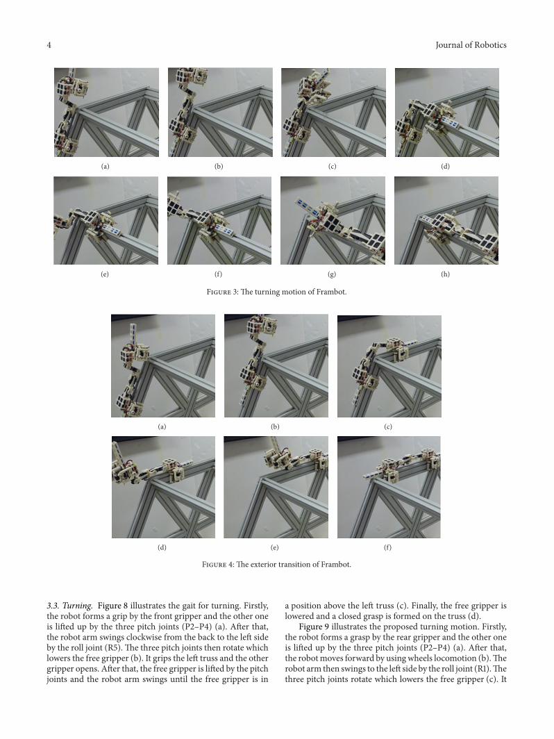
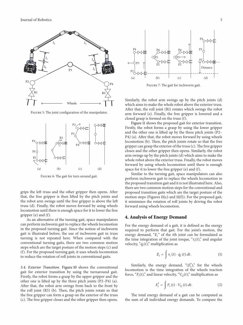
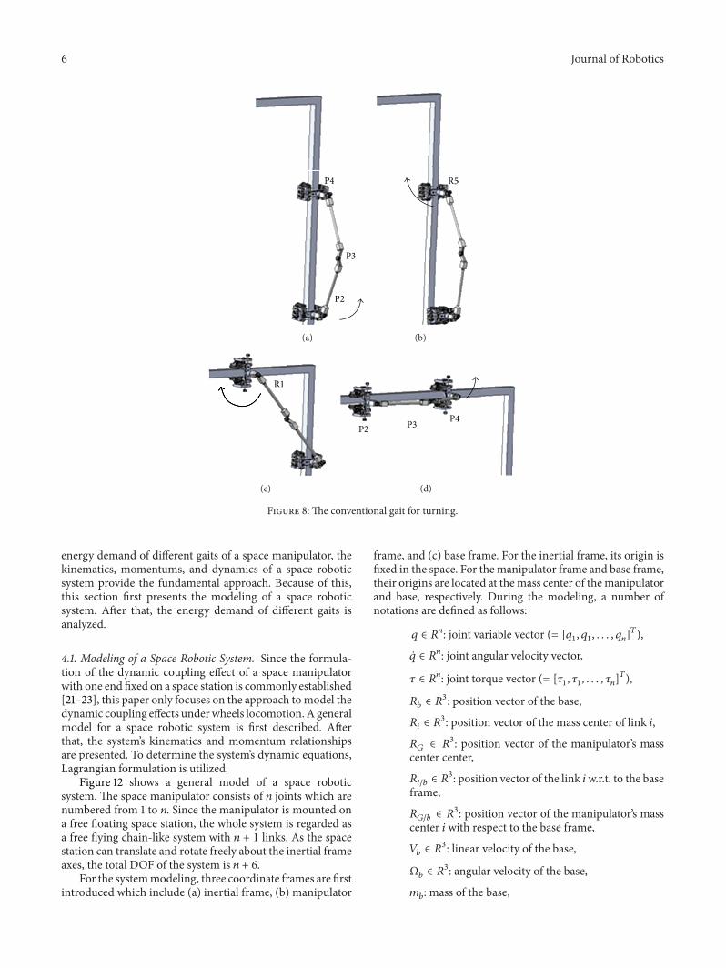

International Journal of
AerospaceEngineeringHindawi Publishing Corporationhttpwwwhindawicom Volume 2014
RoboticsJournal of
Hindawi Publishing Corporationhttpwwwhindawicom Volume 2014
Hindawi Publishing Corporationhttpwwwhindawicom Volume 2014
Active and Passive Electronic Components
Control Scienceand Engineering
Journal of
Hindawi Publishing Corporationhttpwwwhindawicom Volume 2014
International Journal of
RotatingMachinery
Hindawi Publishing Corporationhttpwwwhindawicom Volume 2014
Hindawi Publishing Corporation httpwwwhindawicom
Journal ofEngineeringVolume 2014
Submit your manuscripts athttpwwwhindawicom
VLSI Design
Hindawi Publishing Corporationhttpwwwhindawicom Volume 2014
Hindawi Publishing Corporationhttpwwwhindawicom Volume 2014
Shock and Vibration
Hindawi Publishing Corporationhttpwwwhindawicom Volume 2014
Civil EngineeringAdvances in
Acoustics and VibrationAdvances in
Hindawi Publishing Corporationhttpwwwhindawicom Volume 2014
Hindawi Publishing Corporationhttpwwwhindawicom Volume 2014
Electrical and Computer Engineering
Journal of
Advances inOptoElectronics
Hindawi Publishing Corporation httpwwwhindawicom
Volume 2014
The Scientific World JournalHindawi Publishing Corporation httpwwwhindawicom Volume 2014
SensorsJournal of
Hindawi Publishing Corporationhttpwwwhindawicom Volume 2014
Modelling amp Simulation in EngineeringHindawi Publishing Corporation httpwwwhindawicom Volume 2014
Hindawi Publishing Corporationhttpwwwhindawicom Volume 2014
Chemical EngineeringInternational Journal of Antennas and
Propagation
International Journal of
Hindawi Publishing Corporationhttpwwwhindawicom Volume 2014
Hindawi Publishing Corporationhttpwwwhindawicom Volume 2014
Navigation and Observation
International Journal of
Hindawi Publishing Corporationhttpwwwhindawicom Volume 2014
DistributedSensor Networks
International Journal of