research article new numerical solution of von...
TRANSCRIPT

Research ArticleNew Numerical Solution of von Karman Equation ofLengthwise Rolling
Rudolf Pernis1 and Tibor Kvackaj2
1Alexander Dubcek University of Trencın Pri Parku 19 911 06 Trencın-Zablatie Slovakia2Technical University of Kosice Faculty of Metallurgy 042 00 Kosice Slovakia
Correspondence should be addressed to Tibor Kvackaj tiborkvackajtukesk
Received 10 June 2015 Accepted 16 August 2015
Academic Editor SutasnThipprakmas
Copyright copy 2015 R Pernis and T Kvackaj This is an open access article distributed under the Creative Commons AttributionLicense which permits unrestricted use distribution and reproduction in any medium provided the original work is properlycited
The calculation of average material contact pressure to rolls base on mathematical theory of rolling process given by Karmanequation was solved by many authors The solutions reported by authors are used simplifications for solution of Karman equationThe simplifications are based on two cases for approximation of the circular arch (a) by polygonal curve and (b) by parabolaThe contribution of the present paper for solution of two-dimensional differential equation of rolling is based on description ofthe circular arch by equation of a circle The new term relative stress as nondimensional variable was defined The result fromderived mathematical models can be calculated following variables normal contact stress distribution front and back tensionsangle of neutral point coefficient of the arm of rolling force rolling force and rolling torque during rolling process Laboratory coldrolled experiment of CuZn30 brass material was performed Work hardening during brass processing was calculated Comparisonof theoretical values of normal contact stress with values of normal contact stress obtained from cold rolling experiment wasperformed The calculations were not concluded with roll flattening
1 Introduction
It is likely that the author Karman [1] in the year 1925 wasthe first to submit equation of power balance in the rollgap and derived the two-dimensional differential equationwhich described lengthwise rolling process The followingsimplifications were received
(i) Rolled material has rectangular cross section withinitial thickness ℎ
0and is deformed by cylindrical
rolls to final thickness ℎ1without any action of front
and back tensions(ii) Spread is negligible(iii) Friction coefficient between rolls and rolled material
is constant(iv) Rolls are rigid without any elastic deformation and
bending(v) Rolled material is homogenous and without any
elastic deformation
(vi) Tresca condition of plasticity 1205901minus 1205903= 120590119886
(vii) Flow stress of material in rolling gap is constant(viii) Rolling speed is constant
Geometrical description of roll gap is given in Figure 1and essential formulas are presented in the appendix Fromgraphical scheme of roll gap the result is that all forceshave to be at balance which was the base for derivationtwo-dimensional differential equation describing lengthwiserolling process The procedure of derivation of the two-dimensional differential equation can be found in the classicalliterature of rolling for example Avitzur [2] Hensel andSpittel [3] and Mielnik [4] More recent literatures are thepublications Hajduk and Konvicny [5] and Kollerova etal [6] The stress state in rolling gap describes differentialequation
119889120590119909
119889119909minus120590119899minus 120590119909
119910sdot119889119910
119889119909plusmn120591
119910= 0 (1)
Hindawi Publishing CorporationJournal of Applied MathematicsVolume 2015 Article ID 843720 20 pageshttpdxdoiorg1011552015843720
2 Journal of Applied Mathematics
Y
120572ld R
B dx x
A0
X
2(y+dy
)
2y 1
h1h0
R
120593d120593
Figure 1 Determination of geometric relationships
where plus sign (+) is for forward slip zone minus sign (minus)is for backward slip zone 120590
119899is normal contact stress on rolls
120591 is the shear stress between rolls and rolling material and119909 119910 are the coordinates of the cylinder touching the rolledmaterial
The Tresca condition of plasticity is used for solution of(1)
minus120590119909minus (minus120590
119899) = 120590119899minus 120590119909= 120590119886 (2)
where 120590119910
≐ 120590119899is the maximal principal stress (vertical
direction) 120590119909is the minimal principal stress (horizontal
direction) 120590119886is the flow stress [7ndash9] and 120591 is the shear stress
that is proportional to normal contact stress 120590119899according to
formula
120591 = 119891 sdot 120590119899 (3)
where 119891 is the friction coefficient between rolls and rolledmaterial
Substituting (2) into (3) the following formula will beobtained with only one stress variable 119889120590
119899
119889120590119899
119889119909minus120590119886
119910sdot119889119910
119889119909plusmn119891
119910sdot 120590119899= 0 (4)
Flow stress and friction coefficient are as a constant in (4)If differential equation (4) is divided by flow stress 120590
119886it is
possible to obtain relative normal contact stress 120590119899
120590119899=120590119899
120590119886
(5)
where 120590 is a function
Substituting (5) into (4) the following form is obtained
119889120590119899
119889119909minus1
119910sdot119889119910
119889119909plusmn119891
119910sdot 120590119899= 0 (6)
The application equation (5) can be excluded from (4) mate-rial constant (flow stress 120590
119886) Thus (6) become independent
from the rolled material This differential equation is a lineardifferential equation of first order with the right side andhas a general transcription 120590
119899= 120590119899(119909 119910) The coordinates
119909 and 119910 are defining the geometry of the cylinder which isconnected to the rolling materialThe variable 119910 is a functionof the 119909 coordinate If equation of a circle is substitutinginto (6) so differential equation is obtained which has noanalytical solution till nowThe authorOrowan [10] presentedthe solution of differential equation (1) based on analytical-graphical principle He defined procedure for calculationrolling force rolling torque and electric input for hot andcold rolling processes In the literature [11] showed solutionof differential equation (1) by simulation on analog computerThe authors of [12] solved this case with the use of the circulararc but the result is purely numerical solution The author of[13] presented simplified analytical solution with acceptanceof material work hardening during cold rolling process Thedevelopment in computational software allowed to solve thistask by using finite element method as was given in theliterature [14]
2 Experimental Material and Methods
The investigated material was annealed brass CuZn30 withchemical composition corresponding to standardDIN 17660WNo 20265 The sample sizes before rolling were ℎ times 119887 times 119897
= 34 times 30 times 150mm The samples were laboratory rolledusing duo mill (the diameter of rolls 119863 = 210mm) withconstant circumferential speed of rolls Vroll = 066ms atambient temperatures The temperature of a sample surfaceimmediately after rolling was measured using a thermovisioncamera and was from interval 119879 isin ⟨20 40⟩ [∘C] The coldrolling reductions of thickness were made in an interval120576cold isin ⟨0 30⟩[] as one pass deformation Deformationforces during samples processing by cold rolling were mea-sured by tensometric elements with signal registration inSpider apparatus The static tensile test was performed inaccordance with STN EN 10 002-1 standard
The differential equation of lengthwise rolling processgiven by formula (1) has no analytical solution when contactarc is described with the equation of the circle For solutionof this problem a new combined analytical and numericalapproach is presented
3 Analysis and Results
31 Analysis of the Present Solution of Differential EquationDescribing Stress Condition in Rolling Gap The presentsolutions of differential equation of rolling were based onthe same simplifications because the form of equation is
Journal of Applied Mathematics 3
S1
R120572
120572n
B
N A
h0 h1
xn
ld
Figure 2 The contact arc according to Korolev
complicated More than twenty solutions of differential equa-tion are described in the literature The present solutions ofdifferential equation (1) can be divided into following groups
(i) Geometry of cylinder the circular arc of the cylin-der is being approximated by simplifying curves asstraight line polygonal line and parabola or in somecases using equation of a circle
(ii) Friction conditions between rolls and rolled material
(a) The shear stress between rolls and rolling mate-rial is constant 120591 = 119891 sdot 120590
119886
(b) The shear stress between rolls and rolling mate-rial is changing 120591 = 119891 sdot 120590
119899
(c) Friction coefficient is 119891 = 0
(iii) Mathematical methods of solution analytical analyt-ical-graphical analytical-numerical numerical andsemiempirical
(iv) Work hardening of rolled material most of the solu-tion is based on assumption that material during pro-cessing is without work hardening In a few isolatedcases solution with work hardening of rolled materialwas used
In the following part most frequently ways for calculation of120590 function which are fall to first group will be analyzed
311 The Solution according to Korolev The author Korolev[15] presented solution based on approximation of circulararch by parallel step function which is shown in Figure 2Thecircular arch (BA) is approximated by polygonal line Neutralpoint N divides space of rolling gap on parts backward slipzone (BN) and forward slip zone (NA) Position of neutralpoint is determined by coordinate 119909
119899
119909119899
119897119889
=ℎ1
ℎ0+ ℎ1
(7)
The distribution functions describing relative normal contactstress in rolling gap were divided separately for backward andforward slip zone
The distribution function describing relative normal con-tact stress 120590
119899119861in backward slip zone of rolling gap is as
follows
120590119899119861
= 1198901198980(1minus119909119897119889) (8)
where
1198980= 2119891 sdot
119897119889
ℎ0
(9)
The distribution function describing relative normal contactstress 120590
119899119865in forward slip zone of rolling gap is as follows
120590119899119865
= 1198901198981 sdot(119909119897119889) (10)
where
1198981= 2119891 sdot
119897119889
ℎ1
(11)
The author of [15] on the basis of the previous distributionfunction derived an equation for calculation 120590 function asfollows
120590Kor =1
119898Kor(119890119898Kor minus 1) (12)
where119898Kor is constant
119898Kor = 119891 sdot119897119889
ℎav (13)
312The Solution according to Tselikov The authors Tselikovet al [16] presented solution based on approximation ofcircular arch by straight line function which is shown inFigure 3 The circular arch (BA) is approximated by straightline Neutral point N divides space of rolling gap on partsbackward slip zone (BN) and forward slip zone (NA)Position of neutral point is determined by coordinate 119909
119899and
thickness in neutral section ℎ119899was derived as follows
ℎ119899
ℎ1
= [1
119898 + 1sdot (1 + radic1 + (1198982 minus 1) sdot (
ℎ0
ℎ1
)
119898
)]
1119898
(14)
where119898 is constant
119898 equiv 119898Tsel =2119891 sdot 119897119889
ℎ0minus ℎ1
(15)
The distribution functions describing relative normal contactstress 120590
119899119865in forward slip zone and 120590
119899119861in backward slip zone
of rolling gap are as follows
120590119899119861
=1
119898[(119898 minus 1) sdot (
ℎ0
2119910)
119898
+ 1]
120590119899119865
=1
119898[(119898 + 1) sdot (
2119910
ℎ1
)
119898
minus 1]
(16)
4 Journal of Applied Mathematics
S1
R120572
120572n
B
N A
h0 h1
hn
xn
ld
Figure 3 The contact arc according to Tselikov
S1
R120572
120572n
B
N A
h0 h1
xn
ld
Figure 4 The contact arc approximated by a parabola
The authors of [16] on the basis of the previous distributionfunctions derived an equation for calculation 120590 function asfollows
120590Tsel =2 (1 minus 120576)
120576 (119898 minus 1)sdotℎ119899
ℎ1
sdot [(ℎ119899
ℎ1
)
119898
minus 1] (17)
From (17) the result is that for condition119898 = 1 120590 function isdiscontinuous
313 The Solution according to Bland and Ford The authorsBland and Ford [17] presented solution based on approxima-tion of circular arch by parabolic function which is shownin Figure 4 The circular arch (BA) is approximated by partof parabola Neutral point N divides space of rolling gapon parts backward slip zone (BN) and forward slip zone
(NA) The authors defined neutral angle 120572119899according to the
following formula
120572119899
= radicℎ1
119877
sdot tg[
[
1
2sdot arctg(radic 119877
ℎ1
sdot 120572) minus1
4119891sdot radic
ℎ1
119877sdot ln
ℎ0
ℎ1
]
]
(18)
The distribution functions describing relative normal contactstress 120590
119899119865in forward slip zone and 120590
119899119861in backward slip zone
of rolling gap are as follows
120590119899119861
=ℎ1+ 1198771205932
ℎ0
sdot 119890119891(119867∙
0minus119867∙)
120590119899119865
=ℎ1+ 1198771205932
ℎ1
sdot 119890119891sdot119867∙
(19)
where
119867∙= 2radic
119877
ℎ1
arctg(radic 119877
ℎ1
sdot 120593)
119867∙
0= 2radic
119877
ℎ1
arctg(radic 119877
ℎ1
sdot 120572)
(20)
The authors of [17] on the basis of the previous distributionfunctions derived an equation for calculation 120590 function asfollows
120590Bland-Ford = radic1 minus 120576
120576119898[(1 minus 120576) sdot 119890
2119898sdotarctg(radic120576(1minus120576))
sdot int
119905120572
119905119899
(1 + 11989821199052) sdot 119890minus2119898sdotarctg(119898119905)
sdot 119889119905
+ int
119905119899
0
(1 + 11989821199052) sdot 1198902119898sdotarctg(119898119905)
sdot 119889119905]
(21)
where 119898 is constant and 119905119899 119905120572are limits of integration 119905 =
120593119891
119898 equiv 119898Bland-Ford = 119891 sdot radic119877
ℎ1
(22)
119905119899=120572119899
119891 (23)
119905120572=
1
119898sdot radic
120576
1 minus 120576 (24)
314 The Solution according to Sims The author Sims [18]presented solution of differential equation without consid-eration of friction coefficient Roll radius is considered with
Journal of Applied Mathematics 5
elastic flattening 119877 = 1198771015840 The ratio ℎ
119899ℎ1was derived from
the following formula
ℎ119899
ℎ1
= 1 +2119877
ℎ1
(1 minus cos120572119899) (25)
where
120572119899= radic
ℎ1
119877sdot tg( 120587
16sdot radic
ℎ1
119877sdot ln (1 minus 120576)
+1
2arctg(radic 119877
ℎ1
sdot 120572))
(26)
The distribution functions describing relative normal contactstress 120590
119899119865in forward slip zone and 120590
119899119861in backward slip
zone of rolling gap were calculated according to the followingformulae
120590119899119861
= 1 +120587
4ln((1 minus 120576) (1 +
119877
ℎ1
1205932))
+ 2radic119877
ℎ1
(arctg(radic 119877
ℎ1
sdot 120572) minus arctg(radic 119877
ℎ1
sdot 120593))
120590119899119865
= 1 +120587
4ln(1 + 119877
ℎ1
1205932) + 2radic
119877
ℎ1
sdot arctg(radic 119877
ℎ1
sdot 120593)
(27)
The author of [18] on the basis of the previous distributionfunctions derived an equation for calculation 120590 function asfollows
120590Sim =120587
2radic1 minus 120576
120576arctg(radic 120576
1 minus 120576) minus
120587
4minus radic
1 minus 120576
120576
sdot radic119877
ℎ1
sdot lnℎ119899
ℎ1
+1
2radic1 minus 120576
120576sdot radic
119877
ℎ1
sdot ln 1
1 minus 120576
(28)
315 The Modification Smiryagin Solution by Pernis Theauthors of [19] for solution of (1) presented modification ofTselikov solution using a parabolic approximation functionof the circular arc as is shown in Figure 4 The distributionfunctions describing relative normal contact stress 120590
119899119865in
forward slip zone and 120590119899119861
in backward slip zone of rollinggap were calculated according to the following formulae
120590119899119861
= [1 minus (1199060
119898minus
1
1198982)] 119890119898(1199060minus119906) + 2 (
119906
119898minus
1
1198982)
120590119899119865
= (1 +1
1198982) 119890119898119906
minus 2 (119906
119898+
1
1198982)
(29)
where119898 1199060are constants
119898 equiv 119898Smir-Per =2119891 sdot 119897119889
radicℎ1sdot (ℎ0minus ℎ1)
(30)
1199060= arctg(radic 120576
1 minus 120576) (31)
At this point the Tselikov solution of differential equation(1) was completed The function for calculation of neutralangle and average relative normal contact stress has not beendetermined Additional calculations were carried out by theauthor of [20] which are derived by additional equationsdescribing neutral angle and average relative normal contactstress Location of the neutral point was determined throughusing the value 119906
119899(dimensionless number) and is expressed
by an explicit equation
(051198982 minus 119898 sdot 1199060+ 1) sdot 119890
119898(1199060minus119906119899) minus (051198982 + 1) sdot 119890119898sdot119906119899
+ 2119898 sdot 119906119899= 0
(32)
The neutral point can be obtained from the following for-mula
sin120572119899= radic
1 minus 120576
120576sdot tg119906119899sdot sin120572 (33)
The authors of [20] on the basis of the previous distributionfunctions derived an equation for calculation 120590 function asfollows
120590Smir-Per =2
119898 sdot 1199060
sdot [(1 +2
1198982) sdot (119890119898sdot119906119899 minus 1) +
1199062
0
2
minus 119906119899sdot (119906119899+
2
119898)]
(34)
32 New Approach for Solution of von Karman DifferentialEquation The following approach represents analytic andnumerical solution of (1) where for description of the circulararc equation of circle is applied as is shown in Figure 5 Equa-tion (6) can be classified as the first-order linear differentialequation with right side
119889120590119899
119889119909plusmn119891
119910120590119899=1
119910sdot119889119910
119889119909 (35)
Many authors [21ndash23] have dealt with the solution of this typeof differential equation Firstly (35) will be solved as equationwithout right side
119889120590119899
119889119909plusmn119891
119910120590119899= 0 (36)
which can be divided into the two following differentialequations
119889120590119899119861
119889119909+119891
119910120590119899119861
= 0 (37)
119889120590119899119865
119889119909minus119891
119910120590119899119865
= 0 (38)
6 Journal of Applied Mathematics
S1
R120572
120572n
B
N A
h0 h1
xn
ld
Figure 5 The contact arc described by equation of circle
The following solution of (37) is valid for backward slip zone
int119889120590119899119861
120590119899119861
= minus119891 sdot int119889119909
119910 (39)
The calculation of integral of the left side of the equation canbe carried out as follows
ln (120590119899119861) = minus119891 sdot int
119889119909
119910 120590119899119861
= 119888 sdot 119890minus119891sdotint(119889119909119910)
(40)
If the integral is the exponent and also is a known function1198651(119909) so it is possible to write
1198651(119909) = int
119889119909
119910
respectively 1198891198651(119909)
119889119909=1
119910
(41)
Equation (40) is representing general form of (37) and 119888 isfunction of variable 119909
120590119899= 119888 (119909) sdot 119890
minus119891sdot1198651(119909) (119888 = 119888 (119909)) (42)
Differentiating the equation is obtained from119889120590119899
119889119909=119889119888 (119909)
119889119909sdot 119890minus119891sdot1198651(119909) minus 119888 (119909) sdot
1198891198651(119909)
119889119909sdot 119890minus119891sdot1198651(119909) (43)
Equations (42) and (43) are substituting into (35)119889119888 (119909)
119889119909sdot 119890minus119891sdot1198651(119909) minus 119888 (119909) sdot
1198651(119909)
119889119909sdot 119890minus119891sdot1198651(119909) + 119888 (119909)
sdot1198651(119909)
119889119909sdot 119890minus119891sdot1198651(119909) =
1
119910sdot119889119910
119889119909
(44)
from which function 119888(119909) can be determined as follows119889119888 (119909)
119889119909sdot 119890minus119891sdot1198651(119909) =
1
119910sdot119889119910
119889119909
119888 (119909) = int 119890119891sdot1198651(119909) sdot
119889119910
119910+ 119862
(45)
where 119862 is an integration constant that must be determinedfrom the boundary conditions for each segment separately(backward and forward slip zone)
Substituting (45) into (42) will obtain the general form of(35) for backward slip zone
120590119899119861
= 119890minus119891sdot1198651(119909) sdot (119862
119861+ int 119890119891sdot1198651(119909) sdot
119889119910
119910) (46)
Determination of ratio 119889119910119910 and function 1198651(119909) can be done
using the equation of the circle
1199092+ (119910 minus 119910
0)2= 1198772 (47)
1199100= 119877 +
ℎ1
2 (48)
Separating the variable 119910 from (47) and its differentiation isobtained
119910 = 119877 +ℎ1
2plusmn radic1198772 minus 1199092
119889119910 =119909 sdot 119889119909
radic1198772 minus 1199092
(49)
The next solution is apparent from the description
119889119910
119910=
119909radic1198772 minus 1199092
119877 + ℎ12 minus radic1198772 minus 1199092
119889119909
=119909119877
radic1 minus (119909119877)2
sdot119889119909
119877 (119898 minus radic1 minus (119909119877)2)
(50)
where the constant values are included in one constant119898
119898 = 1 +ℎ1
2119877 (51)
The simplification of (50) can be obtained with transforma-tion fromCartesian coordinates to polar coordinates with useof the following substitution with respect to Figure 6
119909
119877= sin120593
respectively 119889119909 = 119877 cos120593 sdot 119889120593
(52)
Substituting (52) into (50) will obtain the form
119889119910
119910=
sin120593
radic1 minus sin2120593sdot
119877 cos120593 sdot 119889120593
119877(119898 minus radic1 minus sin2120593)
=sin120593
119898 minus cos120593sdot 119889120593 = 119865
2(120593) sdot 119889120593
(53)
where a new function 1198652(120593) is expressed as follows
1198652(120593) =
sin120593119898 minus cos120593
(54)
Journal of Applied Mathematics 7
S
120593R
LK
B
h0
y xA
h1
Figure 6 Definition of the point K[119909 119910]
The function 1198651(120593) can be expressed from (41) according to
the solution defined in work [24] as follows
1198651 (119909) = int
119889119909
119910= int
119889119909
1199100minus radic1198772 minus 1199092
= int119889119909119877
119898 minus radic1 minus (119909119877)2
(55)
Transformation of function1198651(119909) fromCartesian coordinates
to function 1198651(120593) in polar coordinates will be obtained
1198651(120593) = int
cos120593 sdot 119889120593
119898 minus radic1 minus sin2120593= int
cos120593119898 minus cos120593
sdot 119889120593 (56)
where
1198681= int
cos120593119898 minus cos120593
sdot 119889120593 (57)
using the following substitutions
tg120593
2= 119911
cos120593 =1 minus 1199112
1 + 1199112
119889120593 =2119889119911
1 + 1199112
(58)
which are inserted into (57) and the integral is obtained
1198681=
2
119898 + 1int
1 minus 1199112
(1 + 1199112) sdot (119886 + 1199112)sdot 119889119911 (59)
where
119886 =119898 minus 1
119898 + 1 (60)
By decomposition of the integral of (59) to partial fractionsthe following formula is obtained
1198681=
2
119898 + 1(
2
119886 minus 1int
119889119911
1 + 1199112+1 + 119886
1 minus 119886int
119889119911
119886 + 1199112) (61)
0 005 010 015 020 025 030120593 (mdash)
0
10
20
30
40
F1
(mdash)
300
51020
50
100
150
200
Rh
1(mdash
)
Figure 7 Graphical visualization of function 1198651(120593)
and calculation of subintegrals in (61) enters to the form
1198681=
2
119898 + 1(
2
119886 minus 1arctg119911 + 1 + 119886
1 minus 119886sdot1
radic119886arctg 119911
radic119886) (62)
Substituting (60) into (62) will obtain the form
1198681= minus2arctg119911 + 2119898
radic1198982 minus 1arctg(radic119898 + 1
119898 minus 1sdot 119911) (63)
and also substituting (58) into (63) integral 1198681will be in the
form
1198681=
2119898
radic1198982 minus 1arctg(radic119898 + 1
119898 minus 1sdot tg
120593
2) minus 120593 (64)
Integral 1198681represents the analytical form of the function
1198651(120593)
1198651(120593) =
2119898
radic1198982 minus 1sdot arctg(radic119898 + 1
119898 minus 1sdot tg
120593
2) minus 120593 (65)
Transformation Cartesian coordinate 119909 to polar coordinate 120593in (46) and substituting function 119865
2(120593) are obtained from the
form
120590119899119861
= 119890minus119891sdot1198651(120593) sdot (119862
119861+ int 119890119891sdot1198651(120593) sdot 119865
2(120593) sdot 119889120593) (66)
Limits of integration in (66) are ⟨120593 120572⟩ Solution of (38)describing the forward slip process can be obtained by theanalogical way as reported for solving (37)The final solutionof (38) of relative normal contact stress in forward slip zonewill be as follows
120590119899119865
= 119890119891sdot1198651(120593) sdot (119862
119865+ int 119890minus119891sdot1198651(120593) sdot 119865
2(120593) sdot 119889120593) (67)
Limits of integration are ⟨120593 120572⟩ From (66) and (67) the resultis that the relative normal contact stress is proportional to theproduct of two functions 120590
119899asymp 119890119891sdot1198651 sdot 119865
2
Graphical visualization of function 1198651(120593) depending on
angle coordinate and ratio 119877ℎ1is given in Figure 7 Func-
tions 1198651(120593) throughout the observed interval are monotoni-
cally increasing With increasing of ratio 119877ℎ1also functions
8 Journal of Applied Mathematics
0 005 010 015 020 025 030120593 (mdash)
0
5
10
15
20
25
F2
(mdash)
5
1020
50
100
150200
300
500Rh
1(mdash
)
Figure 8 Graphical visualization of function 1198652(120593)
1198651(120593) are rising The function 119865
1(120593) during rolling process
represents wrapping angle of roll 120573 by rolled material (120573is not gripping angle) Graphical visualization of function1198652(120593) depending on angle coordinate is given in Figure 8
Local maximum of functions 1198652(120593) increases with increasing
ratio 119877ℎ1 Location point expressing the maximum value
of the function 1198652(120593) is determined from the condition
1198891198652(120593)119889120593 = 0
cos1205930=
1
119898 (68)
where 1205930is coordinate in maximum and 119898 is constant of
differential equation given by (51)Maximal value of function 119865
2(120593) can be determined from
(54) for coordinate 1205930as follows
1198652max (1205930) =
1
radic1198982 minus 1 (69)
The broken line in Figure 8 shows the positions of themaximal values The integration constants in (66) and (67)must be determined fromTresca condition of plasticity Stressstate according to Figure 1 can be described for point A(output of material from rolling gap) and for point B (inputof material to rolling gap) using the following formulae
0 minus (minus120590119899119861) = 120590119899119861
= 120590119886
0 minus (minus120590119899119865) = 120590119899119865
= 120590119886
(70)
Equations (70) are normalized according to flow stress
120590119899119861
120590119886
=120590119886
120590119886
997904rArr 120590119899119861
= 1 (120593 = 120572)
120590119899119865
120590119886
=120590119886
120590119886
997904rArr 120590119899119865
= 1 (120593 = 0)
(71)
The determination of integration constants is performedwith assumption without work hardening of material duringrolling process without forward and backward stretchingand without roll flattening In the input and output plane ofrolling material the stress is 120590
119909= 0 The integration constant
119862119861for the backward slip zone (120593 = 120572) is found from (66) as
follows
119862119861= 119890119891sdot1198651(120572) (72)
where 1198651(120572) is a known function given by (65) The integra-
tion constant 119862119865for the forward slip zone (120593 = 0) is found
from (67) as follows
119862119865= 1 (73)
The total form of equation for the calculation of the relativenormal contact stress 120590
119899119861for the backward slip zone can be
written as follows
120590119899119861
= 119890minus119891sdot[(2119898radic119898
2minus1)sdotarctg(radic(119898+1)(119898minus1)sdottg(1205932))minus120593]
sdot (119890119891sdot[(2119898radic119898
2minus1)sdotarctg(radic(119898+1)(119898minus1)sdottg(1205722))minus120572]
+ int
120572
120593
119890119891sdot[(2119898radic119898
2minus1)sdotarctg(radic(119898+1)(119898minus1)sdottg(1205932))minus120593]
sdotsin120593
119898 minus cos120593sdot 119889120593)
(74)
and the equation for the calculation of the relative normalcontact stress 120590
119899119865for the forward slip zone can be written as
follows
120590119899119865
= 119890119891sdot[(2119898radic119898
2minus1)sdotarctg(radic(119898+1)(119898minus1)sdottg(1205932))minus120593]
sdot (1
+ int
120593
0
119890minus119891sdot[(2119898radic119898
2minus1)sdotarctg(radic(119898+1)(119898minus1)sdottg(1205932))minus120593]
sdotsin120593
119898 minus cos120593sdot 119889120593)
(75)
The analytical solution of (74) and (75) is problematic becausethe integrals are very complicated and has no primitivefunction Therefore it is necessary to solve integrals 119868
119865and
119868119861using numerical methods
119868119861= int
120572
120593
119890119891sdot1198651(120593) sdot 119865
2(120593) sdot 119889120593
respectively 119868119865= int
120593
0
119890minus119891sdot1198651(120593) sdot 119865
2(120593) sdot 119889120593
(76)
In (6) the first integral is calculated analytically from (36)and second integral is calculated numerically from (45) Thiscombined method for solving differential equations can becalled as analytical-numerical method for solving differentialequation of the rolling process described in (1)
33 Calculation of Neutral Section The two auxiliary con-stants 119886
0and 1198861were used for reducing of calculated time of
function 1198651(120593)
1198860=
2119898
radic1198982 minus 1
1198861= radic
119898 + 1
119898 minus 1
(77)
Journal of Applied Mathematics 9
00 02 04 06 08 1000
05
10
15
20
25
xld (mdash)
120590n
(mdash)
A B
120590nF
N1
N2
N3
1205761
1205762
1205763
120590nB
f = 03 R = 105mm h0 = 7mm1205761 = 10 1205762 = 20 1205763 = 30
Figure 9 The distribution of the relative normal contact stress inrolling gap
Equation (65) is considerably simplified after the introduc-tion of constants
1198651(120593) = 119886
0sdot arctg(119886
1sdot tg
120593
2) minus 120593 (78)
The numerical integration was used for calculation of definiteintegrals described by (74) and (75)
Graphical visualization of the distribution of the relativenormal contact stress in rolling gap depends on relativecoordinate 119909119897
119889and relative deformation is given in Figure 9
From graphical dependence the result is that neutral pointN is significantly dependent on the relative deformationMaterial output from the rolling gap is represented by a pointA and the angle coordinate120593 = 0Material input to the rollinggap is represented by a point B and the angle coordinate120593 = 120572 The influence of friction coefficient on position ofneutral point and distribution of the relative normal contactstress in rolling gap is given in Figure 10 with constant valueof relative deformation (120576 = 20) If the friction coefficient isincreased the peak value of relative normal contact stress israising but weak changes were observed in shifting of neutralpoint depending on relative coordinate 119909119897
119889 The influence
of roll radius on position of neutral point and distributionof the relative normal contact stress in rolling gap is givenin Figure 11 with constant value of relative deformation andfriction coefficient Significant influence of the roll radiusto the peak value of the relative normal contact stress wasobserved but weak effect was observed in shifting of neutralpoint depending on relative coordinate 119909119897
119889
Determination of the neutral point N described by coor-dinate 120572
119899is based on equality of the relative normal contact
stress in backward and forward slip zone as follows
120590119899119865(120572119899) = 120590119899119861(120572119899) (79)
Substituting (74) and (75) into (79) will obtain the formula
119890119891sdot1198651(120572119899) sdot (1 + int
120572119899
0
119890minus119891sdot1198651(120593) sdot 119865
2(120593) sdot 119889120593)
= 119890minus119891sdot1198651(120572119899) sdot (119890
119891sdot1198651(120572) + int
120572
120572119899
119890119891sdot1198651(120593) sdot 119865
2(120593) sdot 119889120593)
(80)
00 02 04 06 08 10xld (mdash)
00
05
10
15
20
120590n
(mdash)
120590nFN1
N2
N3
f1
f2
f3
120590nB
120576 = 20 R = 105mm h0 = 7mmf1 = f2 = f3 =
A B
01 02 03
Figure 10 The distribution of the relative normal contact stress inrolling gap
08
10
12
14
16
18
20
R3
R2
R1
f = 120576 = 30
R1 = 30mmR2 = 100mmR3 = 300mm
00 02 04 06 08 10xld (mdash)
120590nF
N1
N2
N3
120590nB
120590n
(mdash)
A B
010
Figure 11 The distribution of the relative normal contact stress inrolling gap
where function 1198651(120593) is given by (65) and function 119865
2(120593) is
given by (66)The coordinate of neutral angle120572119899is integration
limit The analytical determination of the angle of neutralpoint 120572
119899resulting from (80) is practically impossible and
therefore must be used numerical solution The numericalsolution is based on the step method where interval 120593 isin
⟨0 120572⟩ is scanned with the step Δ119909 The general solution isrepresented with the change of variables as follows 120593 rarr 119909
and 120590 rarr 119910 The conception of numerical solution is shownin Figure 12
The curves of the relative normal contact stress in thesurrounding of pointN are substituted by equation of straightlines in the form119910 = 119896119909+119902 If119909 = 0 then coordinates of pointswill be [119910
1198611 0] and [119910
1198651 0] The slope of the straight lines (119891
and 119887) in interval ⟨119909 119909 + Δ119909⟩ can be described as follows
119896119865=1199101198652minus 1199101198651
Δ119909
119896119861=1199101198612minus 1199101198611
Δ119909
(81)
10 Journal of Applied Mathematics
Table 1 The convergence of calculation of neutral angle 120572119899
119894Δ120593119894
120572119899119894
120572119899119894minus 120572119899119894minus1
120590119899119861119894
120590119899119865119894
120590119899119865119894
minus 120590119899119861119894
(rad) (rad) (rad) (mdash) (mdash) (mdash)1 005 0069 778 523 mdash 2491 510 075 2515 040 042 0023 529 9662 004 0069 753 994 0000 024 530 2492 286 403 2514 257 232 0021 970 8303 003 0069 524 688 0000 229 306 2499 555 775 2506 948 744 0007 392 9694 002 0069 483 702 0000 040 985 2500 857 391 2505 644 227 0004 786 8375 001 0069 413 549 0000 070 153 2503 086 943 2503 412 591 0000 325 6486 0005 0069 410 604 0000 002 946 2503 180 603 2503 318 922 0000 138 3207 0001 0069 408 614 0000 001 990 2503 243 873 2503 255 651 0000 011 7788 00005 0069 408 458 0000 000 156 2503 248 840 2503 250 683 0000 001 8439 00001 0069 408 429 0000 000 001 2503 249 743 2503 249 781 0000 000 038
0
Y
x x + Δx
Δx
Δxn
yB2
b
N
fyB1
yF1
yF2
Figure 12 The neutral point
Equations of the straight lines in interval ⟨119909 119909 + Δ119909⟩ can bedescribed as follows
119910119865=1199101198652minus 1199101198651
Δ119909sdot 119909 + 119910
1198651
119910119861=1199101198612minus 1199101198611
Δ119909sdot 119909 + 119910
1198611
(82)
By comparing the equations of the straight lines 119910119865= 119910119861are
obtained refined local coordinate of the neutral point Δ119909119899
Δ119909119899=
1199101198611minus 1199101198651
1199101198652minus 1199101198612+ 1199101198611minus 1199101198651
sdot Δ119909 (83)
The improved value of the angle of neutral point N (120572119899) will
be obtained from formula
119909119899= 119909 + Δ119909
119899 (84)
The calculation of the neutral angle according to thedescribed algorithm was performed for the following rollingconditions roll radius 119877 = 105mm thickness of materialbefore rolling ℎ
0= 7mm relative deformation 120576 =
30 and friction coefficient 119891 = 03 Result convergence of
0 10 20 30 40 50
120576 ()
000
005
010
015
020
120572n
(mdash)
f =5
10
20
50100200500
Rh1 (mdash)
000
286
573
859
114
120572n
(∘)
010
Figure 13 The dependence of angle of neutral point on relativedeformation and ratio 119877ℎ
1
calculation of neutral angle is given in Table 1 The precisionof calculation is evaluated by difference of values (120590
119899119865119894minus
120590119899119861119894
) Graphical visualization of the angle of neutral pointin dependence on relative deformation and ratio 119877ℎ
1is
given in Figure 13 Work hardening of rolled material is notconsideredThe neutral angle increases with rising of relativedeformation and decreasing of the ratio 119877ℎ
1 Approximate
formula for ratio 120572119899120572 ≐ 05 was presented by the authors of
[16]The validity of formula 120572
119899120572 ≐ 05 is shown in Figure 14
where ratio 120572119899120572 depends on relative deformation and ratio
119877ℎ1 The local maximum is significantly dependent on the
ratio 119877ℎ1
Thematerial thickness in neutral point can be determinedby the neutral angle as follows
ℎ119899= ℎ1+ 2119877 (1 minus cos120572
119899) (85)
Dividing (85) by output thickness ℎ1the ratio ℎ
119899ℎ1can be
obtained in the formℎ119899
ℎ1
= 1 +2119877
ℎ1
(1 minus cos120572119899) (86)
Graphical visualization ratio ℎ119899ℎ1in dependence on relative
deformation and ratio 119877ℎ1for friction coefficient 119891 = 01 is
shown in Figure 15 The ratio ℎ119899ℎ1increases with rising of
relative deformation and decreasing of the ratio 119877ℎ1
Journal of Applied Mathematics 11
0 10 20 30 40 6050
120576 ()
5
10
20
50
100
200
500
Rh
1(mdash
)
f =
040
045
050
055
060
120572n120572
(mdash)
010
Figure 14 Dependence of ratio angle of neutral point and grippingangle on relative deformation and ratio 119877ℎ
1
0 10 20 30 40 50
120576 ()
5 102050100200500
Rh
1(mdash
)
f = 010
100
105
110
115
120
125
hnh
1(mdash
)
Figure 15 Graphical visualization of ratio ℎ119899ℎ1
If the coefficient of friction 119891 = 0 so the status canbe named as the ideal rolling This condition can be usedfor simplified solution of differential equation (4) when it ispossible to continue in solving (80) as follows
int
120572119899
0
1198652(120593) sdot 119889120593 = int
120572
120572119899
1198652(120593) sdot 119889120593 (87)
The value of variable of neutral angle 120572119899is one of integration
limit of function 1198652(120593)-equation (54) The calculation of
integral using substitution and their differential will be asfollows
119905 = 119898 minus cos120593
119889119905 = sin120593 sdot 119889120593
119868 = intsin120593
119898 minus cos120593sdot 119889120593 = int
119889119905
119905= ln (119905)
= ln (119898 minus cos120593)
(88)
0 10 20 30 40 50
120576 ()
510
20
100200500
Rh
1(mdash
)
50
f = 0
000
005
010
015
020
120572n
(mdash)
Figure 16 Neutral angle dependence on deformation and ratio119877ℎ1
Integration in limits 0 le 120593 le 120572119899for forward slip zone obtains
the form
119868119865= int
120572119899
0
sin120593119898 minus cos120593
sdot 119889120593 = [ln (119898 minus cos120593)]1205721198990
= ln (119898 minus cos120572119899) minus ln (119898 minus cos 0)
= ln119898 minus cos120572
119899
119898 minus 1
(89)
and for backward slip zone in limits 120572119899le 120593 le 120572
119868119861= int
120572
120572119899
sin120593119898 minus cos120593
sdot 119889120593 = [ln (119898 minus cos120593)]120572120572119899
= ln (119898 minus cos120572) minus ln (119898 minus cos120572119899)
= ln 119898 minus cos120572119898 minus cos120572
119899
(90)
The neutral angle of ideal rolling process can be calculatedfrom comparison of (89) and (90) as follows
cos120572119899= 119898 minus radic(119898 minus 1) sdot (119898 minus cos120572) (91)
Substituting (51) to (91) and using simplification cos120572 asymp 119877ℎ1
the next formula will be obtained
120572119899= arccos(1 + (1 minus
1
radic1 minus 120576)ℎ1
2119877) (92)
Graphical visualization equation (92) is given in Figure 16The neutral angle is increased with rising of relative defor-mation and decreasing of ratio 119877ℎ
1 From comparison of
dependences shown in Figure 13 (119891 = 01) Figure 16 (119891 = 0)is the result that neutral angle is slightly higher if frictioncoefficient119891 = 0 Equation (92) can be considered as simplestform for direct calculation of neutral angle with satisfyingresults
34 Calculation of Average Normal Contact Stress The dis-tribution of relative normal contact stress to rolls in plasticdeformation zone is shown in Figures 9 10 and 11 by the
12 Journal of Applied Mathematics
N
120590nF(120593) 120590nB(120593)
F
GO
E
A B
120590n
av120590max
120590a=1
120590a=1
120572n
120572
Figure 17 The average relative normal contact stress 120590
curves ANB The rolling force can be calculated from theaverage relative normal contact stress 120590
119899av along grippingangle 120572 (surface of rectangular OEFGO) as is given inFigure 17
It is supposed the egality of surfaces OANBGO equiv
OEFGO If it is valid that 120590 = 120590119899av then the following can
be written
120590 =1
120572 minus 0sdot int
120572
0
120590119899(120593) sdot 119889120593 (93)
The calculation of 120590 must be done independently for back-ward and forward slip zone according to the followingformula
120590 =1
120572sdot [int
120572119899
0
120590119899119865(120593) sdot 119889120593 + int
120572
120572119899
120590119899119861(120593) sdot 119889120593] (94)
Substituting (74) and (75) to (94) is obtained in the followingform
120590 =1
120572sdot [int
120572119899
0
(119890119891sdot1198651(120593)
sdot (1 + int
120593
0
119890minus119891sdot1198651(120593) sdot 119865
2(120593) sdot 119889120593)) sdot 119889120593
+ int
120572
120572119899
(119890minus119891sdot1198651(120593)
sdot (119890119891sdot1198651(120572) + int
120572
120593
119890119891sdot1198651(120593) sdot 119865
2(120593) sdot 119889120593)) sdot 119889120593]
(95)
The limits of integration for a forward slip zone are definedby interval 120593 isin ⟨0 120572
119899⟩ and calculation of 120590
119899119865is performed
according to (75) Identically it is valid for backward slip zonewhere120593 isin ⟨120572
119899 120572⟩ and calculation of120590
119899119861is performed accord-
ing to (74)The definite integrals in (95) can be performed bysome numerical mathematical method Graphical visualiza-tion of (1) is given in Figure 18 Function 120590 throughout theobserved interval is monotonically increasing The relativenormal contact stress is increased with rising of relative
0 10 20 30 40 50
120576 ()
1020
7550
150
100
200
300
Rh
1(mdash
)
f = 010
10
12
14
16
18
20
120590(mdash
)
Figure 18 The dependence of function 120590 on relative deformation 120576and ratio 119877ℎ
1
00 05 10 15 20 25 30ldhav (mdash)
10
12
14
16
18
120590(mdash
)
f = 040
10203040
10203040
10203040
120576(
)
f = 025
f = 010
Figure 19The dependence of function 120590 on ratio 119897119889ℎav and relative
deformation
deformation and decreasing of ratio 119877ℎ1 Dependence of
relative normal contact stress on ratio 119897119889ℎav and relative
deformation for three groups of friction coefficient are givenin Figure 19 From dependence the result is that the strongesteffect on relative normal contact stress has friction coefficient
For numerical integration of (95) Simpsonrsquos quadraturerule can be used The author of [24] presented Weddleformula which is more effective than Simpsonrsquos quadraturerule for numerical calculation of general function 119891(119909) Theadvantage of this numerical method is faster convergenceof calculation The continuous function 119891(119909) is numericallyintegrated in interval 119909 isin ⟨119886 119887⟩ where 119887 gt 119886 which is dividedon final number of subinterval with step ℎ as follows
ℎ =119887 minus 119886
119899 (96)
where 119899 is the whole positive number
int
119887
119886
119891 (119909) sdot 119889119909 =3
10ℎ (1199100+ 51199101+ 1199102+ 61199103+ 1199104+ 51199105
+ 21199106+ 51199107+ 1199108+ 61199109+ 11991010+ 511991011+ 211991012+ 511991013
+ 11991014+ sdot sdot sdot + 6119910
119899minus3+ 119910119899minus2
+ 5119910119899minus1
+ 119910119899)
(97)
where 1199100= 119891(119886) 119910
1= 119891(119886 + ℎ) 119910
2= 119891(119886 + 2ℎ) 119910
3=
119891(119886 + 3ℎ) 119910119894= 119891(119886 + 119894 sdot ℎ) and 119910
119899= 119891(119887) 119894 is the
Journal of Applied Mathematics 13
Table 2 The convergence of calculation of 120590 function according toWeddle formula
119894 119899 120590119899119861119894
120590119899119861119894
minus 120590119899119861119894minus1
1 6 4116 857 469 mdash2 12 4116 875 359 minus0000 017 8893 18 4116 875 502 minus0000 000 1434 24 4116 875 512 minus0000 000 0105 30 4116 875 514 minus0000 000 0026 36 4116 875 514 0000 000 000
whole positive number (119894 = 1 2 3 119899) The calculation ofrelative normal contact stress in backward slip zone-equation(66) according to Weddle formula is given in Table 2 Theprecision of calculation is evaluated according to differenceof values 120590
119899119861119894minus 120590119899119861119894minus1
The satisfied precision of calculation120590119899119861119894
is obtained after 119899 = 18 where (120590119899119861119894
minus 120590119899119861119894minus1
) asymp 110minus6
Boundary conditions of rolling process were given asfollows relative deformation 120576 = 60 ratio 119877ℎ
1= 10
friction coefficient119891 = 02 and angle coordinate 120593 = 005 radFrom comparison of numerical calculations the result is thatnumerical integration according to Weddle formula is fourtimes faster than numerical integration realized according toSimpsonrsquos quadrature rule
The previous calculations were carried out providedwithout work hardening of material during rolling process
In the next part the rolling process with acceptanceof isotropic work hardening of material will be describedAlexander [25] mentions Swift described work hardeningcurves according to formula
119884119878 = 1198841198780sdot (1 + 119861 sdot 120576)
119899 (98)
where 119884119878 is the uniaxial yield stress from static tensile testdepending on true strain 120576 = ln(ℎ
0ℎ1) 1198841198780is the uniaxial
yield stress from static tensile test resulting from annealingstate of material and 119861 119899 is the material constants
The average value of flow stress can be calculated asfollows
120590119886av =
1
1205762minus 1205761
int
1205762
1205761
120590119886119889120576 (99)
where 1205761is the true strain before actual rolling and 120576
2is the
final true strain after rollingFor calculation of flow stress the author of [25] used the
formula inwhich effective stress and effective strain are given
120590119886=
2
radic3sdot 1198841198780sdot (1 +
2
radic3sdot 119861 sdot 120576)
119899
(100)
Substituting (100) into (99) the following is obtained
120590119886av =
1
1205762minus 1205761
int
1205762
1205761
2
radic3sdot 1198840sdot (1 +
2
radic3sdot 119861 sdot 120576)
119899
sdot 119889120576 (101)
00 02 04 06 08
120576 (mdash)
0
100
200
300
400
500
600
YS
(MPa
)
CuZn30
YS = 156(1 + 5008356 middot 120576)034971
R2 = 09912
Figure 20 Uniaxial stress-strain curve for brass CuZn30
and after integration average value of flow stress has a form
120590119886av =
1198841198780
(119899 + 1) sdot (1205762 minus 1205761) sdot 119861
[(1 +2
radic3sdot 119861 sdot 1205762)
119899+1
minus (1 +2
radic3sdot 119861 sdot 1205761)
119899+1
]
(102)
Let us assume that material is processing by rolling fromannealed state for which 120576
1= 0 is valid and transform upper
limit of integral 1205762= 120576 (102) is simplified to form
120590119886av =
1198841198780
(119899 + 1) sdot 120576 sdot 119861[(1 +
2
radic3sdot 119861 sdot 120576)
119899+1
minus 1] (103)
The measurements values of yield stress depending on truestrain of laboratory cold rolling experiment are given inFigure 20 For approximation of measurement values ofstress-strain curve (98) was used Final regression equationof stress-strain curve for brass CuZn30 has a form
119884119878 = 156 sdot (1 + 5008356 sdot 120576)034971 (104)
Graphical visualization of (104) is given in Figure 20Substituting (104) into (103) the following formula is
obtained
120590119886av =
230775120576
[(1 + 5783152 sdot 120576)134971 minus 1] (105)
Measured and calculated data from experimental cold rollingschedule are given in Table 3 The calculation of deformationresistance was carried out according to formula
120590119863=119865119903
119878 (106)
where 119865119903is the rolling force and 119878 is the contact surface of
rolled material with rollThe average relative normal contact stress calculated from
measurement data is given as follows
120590meas =120590119863
120590119886av
(107)
14 Journal of Applied Mathematics
Table 3 Measured and calculated data from experimental cold rolling schedule
Number 120576 120576 119877ℎ1
119878 119865119903
120590119863
120590119886av 120590meas 120590 120590meas minus 120590
() (mdash) (mdash) (mm2) (kN) (MPa) (MPa) (mdash) (mdash) (mdash)1 1039 01097 3477 15710 65 41376 27941 1431 1251 01802 1746 01918 3763 23018 110 47789 32540 1423 1371 00523 2269 02573 4054 24776 137 55296 35538 1512 1468 00444 2738 03199 4303 28069 165 58784 38055 1506 1560 minus00545 3006 03575 4468 31700 178 56151 39441 1390 1617 minus0226
120576 (mdash)
120590m
eas120590
(mdash)
120590meas
120590
010 015 020 025 030 035 04010
12
14
16
18
20
h0 = 337mm = 066msR = 105mm
CuZn30
Figure 21 Uniaxial stress-strain curve for brass CuZn30
Average value of flow stress is calculated according to (105)Theoretical value of 120590 function is calculated according to(95) with friction coefficient 119891 = 02 Numeric comparisonof measured and theoretically calculated values of 120590 functionis given in Table 3 and graphical comparison is shown inFigure 21
The differences between measured and calculated valuesof the average relative normal contact stress are from intervalΔ isin ⟨3 14⟩[] These deviations are resulting from thecalculation which does not take into account the flatteningrolls
35 Calculation of Front and Back Tensions Back tension isactuating in direction of119909-axis andmarked by label120590
1199090 Front
tension is actuating in direction of 119909-axis andmarked by label1205901199091 According to Figure 1 point B is valid 119909 = 119897
119889and tension
stress 120590119909
= 1205901199090 The tension stresses 120590
1199090and 120590
1199091can be
described by using flow stress as follows
1205901199090
= 1205850sdot 120590119901
1205901199091
= 1205851sdot 120590119901
(108)
where 1205850and 120585
1are coefficient for back and front tensions
0 le 1205850lt 1 (for without the back tension 120585
0= 0 and for
maximal back tension have to be valid 1205850lt 1) and 0 le 120585
1lt 1
(for without the front tension 1205851= 0 and for maximal front
tension have to be valid 1205851lt 1)
Using the Tresca condition of plasticity formulae of plas-ticity of material for backward and forward slip zones will beobtained as follows
120590119899119861minus (minus120590
1199090) = 120590119899119861+ 1205901199090
= 120590119901
120590119899119865
minus (minus1205901199091) = 120590119899119865
+ 1205901199091
= 120590119901
(109)
Editing of (109) is received
120590119899119861
120590119886
=120590119886
120590119886
minus1205850120590119886
120590119886
(110)
997904rArr 120590119899119861
= 1 minus 1205850 (111)
120590119899119865
120590119886
=120590119886
120590119886
minus1205851120590119886
120590119886
(112)
997904rArr 120590119899119865
= 1 minus 1205851 (113)
The integration constants 119862119861and 119862
119865which are describing
front and back tensions can be determined from limitconditions given by (111) and (113) The integration constant119862119865for forward slip zone and for 120593 = 0 resulting from (67)
will be as follows
119862119865= 1 minus 120585
1 (114)
The integration constant 119862119861for backward slip zone and for
120593 = 120572 resulting from (66) will be as follows
119862119861= (1 minus 120585
0) sdot 119890119891sdot1198651(120572) (115)
The formula for calculation of relative normal contact stressat forward slip zone with consideration of front tension willbe as follows
120590119899119865
= 119890119891sdot1198651(120593)
sdot ((1 minus 1205851) + int
120593
0
119890minus119891sdot1198651(120593) sdot 119865
2(120593) sdot 119889120593)
(116)
And for calculation of relative normal contact stress atbackward slip zone with consideration of back tension willbe as follows
120590119899119861
= 119890minus119891sdot1198651(120593)
sdot ((1 minus 1205850) sdot 119890119891sdot1198651(120572) + int
120572
120593
119890119891sdot1198651(120593) sdot 119865
2(120593) sdot 119889120593)
(117)
Journal of Applied Mathematics 15
00 02 04 06 08 10xld (mdash)
00
05
10
15
20
25120590
(mdash)
1205851 = 0
120576 = 20 R = 105mmf = 03
AN6
N4
N2
N0120590nF 120590nB
B0
B2
B4
B6
B0B2B4B6
12058500 = 0
12058502 = 02
12058504 = 04
12058506 = 06
h0 = 7mm
rarr
rarr
rarr
rarr
Figure 22 The dependence of function 120590 on ratio 119909119897119889and back
tension
00 02 04 06 08 10xld (mdash)
00
05
10
15
20
25
120590(mdash
)
1205850 = 0
120576 = 20 R = 105mmf = 03h0 = 7mm
N6
N4
N2
N0
A0
A2
A4
A6
A0
A2
A4
A6
12058510 = 0
12058512 = 02
12058514 = 04
12058516 = 06
B
rarr
rarr
rarr
rarr
Figure 23 The dependence of function 120590 on ratio 119909119897119889and front
tension
The function 1198651(120593) was described by (65) and function 119865
2(120593)
by (64) The distribution of the relative normal contact stressin rolling gap depends on relative coordinate 119909119897
119889and back
tension is given in Figure 22 From graphical dependence theresult is that neutral point N is significantly dependent onthe back tension If coefficient of front tension is 120585
1= 0
then front tension stress will be 1205901199091
= 0 The back tensionstress described by flow stress will be given by coefficient 120585
0
The value of back tension is characterizing by point B Forexample for point B
4being 12058504 = 04 it means that back
tension will be as follows 1205901199090
= 04120590119886
If the back tension increases then average relative normalcontact stress is decreased The front and back tensions arenot active in neutral pointN
0 The neutral point is shifting to
exit side of rolling gap with increase of back tensionThe distribution of the relative normal contact stress in
rolling gap depends on relative coordinate 119909119897119889and front
tension is given in Figure 23 From graphical dependence theresult is that neutral point N is significantly dependent onthe front tension If coefficient of back tension is 120585
0= 0
then back tension stress will be 1205901199090
= 0 The front tensionstress described by flow stress will be given by coefficient 120585
1
The value of front tension is characterized by point A Forexample for point A
4being 12058514 = 04 it means that back
tension will be as follows 1205901199091
= 04120590119886
00 02 04 06 08 10xld (mdash)
00
05
10
15
20
25
120590(mdash
)
12058510 = 0
12058512 = 02
12058514 = 04
12058516 = 06
12058500 = 012058502 = 0212058504 = 0412058506 = 06
120590nF 120590nB
N60
N66
N06
N00
1205850 = 1205851
120576 = 20 R = 105mm f = 03h0 = 7mm
B0
B2
B4
B6
A0
A2
A4
A6
Figure 24 The dependence of function 120590 on ratio 119909119897119889back and
front tension
0 01 02 03 04 05f (mdash)
10
15
20
25
30
35
40
120590(mdash
)
5
10
15
20304050120576 ()
Rh1 = 100
Figure 25 The dependence of function 120590 on friction coefficient
The common action of back and front tension on thedistribution of the relative normal contact stress in rolling gapdepends on relative coordinate 119909119897
119889that is given in Figure 24
The indexing of pointN119909119910
is as follows 119909 is the tension stresson enter side of material to rolling gap 119910 is the tension stresson exit side of material from rolling gapThis means thatN
00
is representing intersection point of curves without action offront and back tension 120585
0= 1205851= 0 forN
66it is for maximal
values of front and back tension 1205850= 1205851= 06
36 Calculation of Friction Coefficient The simple deter-mination of friction coefficient can be used with graphicaldependence given in Figure 25 for constant ratio 119877ℎ
1=
100 More precisely determination of friction coefficientdepends on deformation resistance of rolled material Thedeformation resistance of rolled material 120590
119863is characterized
by three-axial stress state and depends on friction coefficientbetween rolls and rolled material In the case of actiononly one-axial stress state is function of friction eliminatedand stress is defined as flow stress 120590
119886 If ratio 119877ℎ
1and
deformation 120576 are constant then the relative normal contactstress in rolling gap depends only on friction coefficientMathematical expression describing relationship between 120590
119863
and 120590119886can be given as follows
120590119863= 120590119886sdot 1205900 (118)
16 Journal of Applied Mathematics
0 01 02 03 04 05f2
f (mdash)
minus10
minus05
00
05
10
15
Δ120590(f
)(mdash
)
1205900 = 1506
120576 = 2738
f0 = 0fmax
= 0577
Rh1 = 4303
Figure 26 The dependence of function Δ120590 on friction coefficient
From (118) the following can be determined
1205900=120590119863
120590119886
(119)
Substituting (119) into (95) and subtraction of (119) from (95)is obtained
Δ120590 = 120590 (119891) minus 1205900 (120)
Graphical dependence of Δ120590 is given in Figure 26 Intersec-tion point of curve describing Δ120590 function with zero valueof 119909-axis is the determining value of friction coefficient 119891
2
The value of friction coefficient 1198912valid for given conditions
of rolling process For numerical calculation of frictioncoefficient Regula Falsi method was used Maximal value offriction coefficient results from
(i) Tresca condition of plasticity 1198911= 05
(ii) HMH condition of plasticity 1198911= 0577
The first approximation for calculation of friction coefficient1198912using Regula Falsi method will be as follows
1198912=1198910sdot Δ120590 (119891
1) minus 1198911sdot Δ120590 (119891
0)
Δ120590 (1198911) minus Δ120590 (119891
0)
(121)
The calculation of friction coefficient 1198912using Regula Falsi
method for rolling conditions given in Table 3 line number4 (1205900= 1506 ratio 119877ℎ
1= 4303 120576 = 2738) is shown
in Table 4 Calculation precision on three decimal positions(1198912= 0182) was obtained after 119899 = 7 steps
37 Calculation of Coefficient of the Arm of Rolling Force Therolling torque of rolling process depends on the coefficientof the arm of rolling force 120595 and the rolling force 119865
119903 The
coefficient of the arm of rolling force is calculated accordingto the following formula
120595 =119886
119897119889
(122)
where 119886 is the arm of rolling force and 119897119889is the length of
contact arc
Table 4The calculation of friction coefficient 1198912using Regula Falsi
method
1198991198910
1198911
Δ120590(1198910) Δ120590(119891
1) 119891
2Δ120590(1198912)
(mdash) (mdash) (mdash) (mdash) (mdash) (mdash)0 0 05 minus044 1968 1433 027 0117 858 minus0174 4441 0117 858 05 minus0174 444 1433 027 0159 329 minus0064 8072 0159 329 05 minus0064 807 1433 027 0174 069 minus0023 1843 0174 069 05 minus0023 184 1433 027 0179 258 minus0008 1764 0179 258 05 minus0008 176 1433 027 0181 077 minus0002 8695 0181 077 05 minus0002 869 1433 027 0181 715 minus0001 0056 0181 715 05 minus0001 005 1433 027 0181 938 minus0000 3527 0181 938 05 minus0000 352 1433 027 0182 016 minus0000 1238 0182 016 05 minus0000 123 1433 027 0182 043 minus0000 043
The development of the relative normal contact stress incoordinates 120590
119899minus 120593 is shown in Figure 17 from which the
result is that surface is delimited by pointsOANBGO on theinterval 120593 isin ⟨0 120572⟩
The resultant of the force is determined from the anglegravity centre120593 = 120572
119886inwhich the force actsThe angle gravity
centre120572119886of the stress surfaceOANBGO is defined as the ratio
of static moment119872119878and the stress surface 119878
120590
120572119886=119872119878
119878120590
(123)
The stress surface 119878120590can be determined as follows
119878120590= 120572 sdot 120590 (124)
where 120572 is the gripping angle and 120590119899av is the average relative
normal contact stressThe static moment119872
119878then can be determined as follows
119872119878= int
120572
0
120593 sdot 120590119899(120593) sdot 119889120593 (125)
Result from Figure 27 can be described forward slip zoneby curve with points AN and angle coordinate 120593 isin ⟨0 120572
119899⟩
backward slip zone by curve with points NB and anglecoordinate 120593 isin ⟨120572
119899 120572⟩ The solution of integral equation
(125) is performed by numerical integration separately forbackward and forward slip zone as follows
119872119878= int
120572119899
0
120593 sdot 120590119899119865(120593) sdot 119889120593 + int
120572
120572119899
120593 sdot 120590119899119861(120593) sdot 119889120593 (126)
where 120590119899119865(120593) is described by (75) and 120590
119899119861(120593) is described by
(74)The calculation of integrals is carried out by Weddle
formulae [24] Length of arm of force action is calculatedusing the following formula
119886 = 119877 sdot sin120572119886 (127)
The numerical calculation and visualization of the coefficientof arm of rolling force 120595 depends on the relative deformation
Journal of Applied Mathematics 17
120590n
120590nF(120593)
A
N
120590nB(120593)
B
120593
120590a=1
120590a=1
Fr
120590ni(120593i)
Δ120593
120593i
120572n
120572a
120572
GO
Figure 27 The determination of angle gravity centre 120572119886as a point
of rolling force 119865119903
0 10 20 30 40 50
120576 ()
047
048
049
050
051
Ψ(mdash
)
f = 010
500
200
100
50
20105
Rh
1(mdash
)
Figure 28The dependence of the coefficient of arm of rolling force120595 on relative deformation
and ratio 119877ℎ1is shown in Figure 28 From graphical depen-
dence the result is that the coefficient of the arm of rollingforce is decreased with increase of relative deformation andration 119877ℎ
1
The coefficient of arm of rolling force can be determinedalso from the following formula [3]
120595 =120572119886
120572 (128)
The authors of [3] introduce calculation of 120595 the followingapproximated formula 120595 = 120572
119886120572 ≐ 05 From the graphical
dependence in Figure 28 the result is that value can beobtained only if deformation 120576 = 0
38 Calculation of Rolling Force and Rolling Torque Thecalculation of rolling force can be performed by the followingformula
119865119903= 120590119886sdot 120590 sdot 119897119889sdot 119887av (129)
f
120572
120576
Rh1
Figure 29 Rolling gap parameters
and rolling torque of two rolls can be performed by thefollowing formula
119872119903= 2119865119903sdot 119886 (130)
The arm of rolling force resulting from (122) can be expressedas follows
119886 = 120595 sdot 119897119889 (131)
Substituting (129) and (131) into (130) formula for calculationof rolling torque is obtained
119872119903= 2119877 sdot 120590
119886sdot 120590 sdot 120595 sdot Δℎ sdot 119887av (132)
The value of coefficient of arm of rolling force 120595 is given inFigure 28
4 Discussion
The solution of difference equation (1) realized by the authorsof [15ndash18] was based on determining only one constant119898 which consists of product of friction coefficient andgeometrical characteristics of rolling gap
The constant according to Korolev [15] 119898Kor describedby (13) is depending on product of friction coefficient andratio 119897
119889ℎav The constant according to Tselikov et al [16]
119898Tsel described by (15) is depending on product of frictioncoefficient and ratio 2119897
119889(ℎ0minus ℎ1) The constant according to
Bland-Ford [17] 119898Bla-For described by (22) is depending onproduct of friction coefficient and ratioradic119877ℎ
1 The constant
according to Smiryagin-Pernisov [19] 119898Smir-Per described by(30) is depending on product of friction coefficient and ratio2119897119889radicℎ1(ℎ0minus ℎ1)
In the new solution of difference equation (1) presented bythis paper from calculation of 119898 constant is separating fric-tion coefficient and is described by (51) which is dependingonly on geometry of rolling gap given by ratio 119877ℎ
1
Each of constants is described by (13) (15) and (22)Equation (30) contains deformation in some form butthe deformation does not directly include (74) and (75)The interrelationship characteristics of rolling gap can beschematically shown in Figure 29
18 Journal of Applied Mathematics
Table 5 The calculations 120590 function according to (95) and 120590Kor function by a Korolev
ℎ0
ℎ1
120576 119877 119877ℎ1
119897119889ℎav 119891 119898Kor 120590Kor 120590 120590Kor120590
(mm) (mm) (mdash) (mm) (mdash) (mdash) (mdash) (mdash) (mdash) (mdash) (mdash)20 15259 02371 105 68813 4000 01 0400 12296 12742 0965050 41935 01613 105 25038 2000 02 0400 12296 12586 0977070 62550 01064 105 16786 13334 03 0400 12296 12482 09851
Table 6 The calculations 120590 function according to (95) and 120590Tsel function by Tselikov
ℎ0
ℎ1
120576 119877 119877ℎ1
119897119889ℎav 119891 119898Tsel 120590Tsel 120590 120590Tsel120590
(mm) (mm) (mdash) (mm) (mdash) (mdash) (mdash) (mdash) (mdash) (mdash) (mdash)20 15338 02331 105 68455 3957 01 3000 12024 12705 0946350 31416 03717 105 33422 3424 02 3000 13930 15299 0910670 28416 05941 105 36951 4225 03 3000 19655 25319 07763
Table 7 The calculations 120590 function according to (95) and 120590Bla-For function by Bland-Ford
ℎ0
ℎ1
120576 119877 119877ℎ1
119897119889ℎav 119891 119898Bla-For 120590Bla-For 120590 120590Bla-For120590
(mm) (mm) (mdash) (mm) (mdash) (mdash) (mdash) (mdash) (mdash) (mdash) (mdash)0328 02625 02 105 400 8888 01 2000 15573 17177 090661500 10500 03 105 100 5388 02 2000 17075 20049 085173938 23625 04 105 44444 4075 03 2000 18295 23162 07897
Table 8 The calculations 120590 function according to (95) and 120590Sim function by Sims
ℎ0
ℎ1
120576 119877 119877ℎ1
119897119889ℎav 119891 119898Sim 120590Sim 120590 120590Sim120590
(mm) (mm) (mdash) (mm) (mdash) (mdash) (mdash) (mdash) (mdash) (mdash) (mdash)60 42 03 105 25 2690 01 5000 14380 12493 1151060 42 03 105 25 2690 02 5000 14380 14540 0989060 42 03 105 25 2690 03 5000 14380 17011 08453
From Figure 29 and the Appendix the result is thepossibility of mutual replacement of one parameter by theother but friction coefficient does not depend on any ofthese parameters The new solution of differential equation(1) based on calculation of the relative normal contactstress 120590 depending on two functions can be compared withcalculation of 120590 functions according to the authors of [15ndash18] The examples of calculations of 120590 functions accordingto the authors of [15ndash18] with comparison of calculation 120590
function according to (95) are given in Tables 5 6 7 and 8Graphical comparison of calculations of differential equation(1) resulting from various approaches defined by the authorsof [15ndash17] and calculation given by (95) is shown in Figure 30
The length of rolling gap is defined by relative coordinate119909119897119889 Entry side to rolling gap is marked by point B and exit
side from rolling gap by point A The maximal values of therelative normal contact stress 120590 were obtained by using (95)
5 Conclusion
The solutions of von Karman two-dimensional differentialequation of lengthwise rolling process were based on cer-tain simplifications which are describing the geometry ofsurface of circular cylinder Circular arch of roll gap was so
00 01 02 03 04 05 06 07 08 09 10xld (mdash)
120590(mdash
)
10
12
14
16
18
20
A B
f = R = 105mm120576 = 30h0 = 7mm
120572 = 01415
Pernis-KvackajKorolev
TselikovBland-Ford
02
Figure 30 The distribution of the relative normal contact stress inrolling gap
far approximated by simplified curves (polygonal curve orparabola) because his accurate description using the equationcircle did not create an analytical solution of the differential
Journal of Applied Mathematics 19
equation (1) Use of any approximated formulas leads toinaccuracy of calculations relative to normal contact stressalong the length of the contact arc Attempts have been madeto describe the contact arc of a circle by the equation ofthe circle but the exact solution of (1) has been replaced byapproximate solution using numerical simulation in softwareDeform
The proposed solution presents a new approach to thedescription of the circular arch of rolling gap by equation of acircle For this approach which is describing the circular archof rolling gap by equation of a circle the classical analyticalsolution of deferential equation cannot be used Thereforenew solution of deferential equation based on interactiontwo methods was suggested and realizedThe authors namedthis solution with term analytic numerical solution Also theappropriate solutionwas the transformation of the coordinatesystem from rectangular to polar coordinates The distribu-tion of the relative normal contact stress to rolls is dependenton two independent functions 120590
119899asymp 1198651sdot1198652The first function
has exponential form 1198651
= 119890119865(119891120593) and is describing the
influence of the friction between roll and rollingmaterialThesecond function has trigonometric form 119865
2= 1198652(119898 120593) and
is describing geometry of rolling gap and is independent onfriction coefficient
The results from the numerical calculations are carriedout geometric visualizations for neutral section normal con-tact stress distribution front and back tensions coefficient ofthe arm of rolling force rolling force and rolling torque independ on rolling conditions
Result from laboratory cold rolled experiment of CuZn30material was derived equation describing work hardening ofobserved material This equation was used for calculationof the relative normal contact stress 120590 with consideration ofwork hardening during material processing Comparison oftheoretical values of 120590 function calculated according to (95)with values of 120590 function calculated based on experimentalresults from cold rolled was performed The solution of (1)was not concluded with roll flattening
Appendix
Absolute deformation is as follows
Δℎ = ℎ0minus ℎ1 (A1)
Relative deformation is as follows
120576 =ℎ0minus ℎ1
ℎ0
(A2)
True strain is as follows
120576 = ln(ℎ0
ℎ1
) (A3)
respectively
120576 = minusln (1 minus 120576) (A4)
Ratio ℎ1ℎ0rarr ℎ
1ℎ0= 1 minus 120576
Average thickness is as follows
ℎav =ℎ0+ ℎ1
2 (A5)
Gripping angle is as follows
cos120572 = 1 minusΔℎ
2119877 (A6)
respectively
cos120572 = 1 minus120576
1 minus 120576sdotℎ1
2119877 (A7)
Length of contact arc is as follows
119897119889= radic119877Δℎ minus
Δℎ2
4 (A8)
respectively
119897119889≐ radic119877Δℎ (A9)
Ratio 119897119889ℎav rarr 119897
119889ℎav = 2(radic119877Δℎ(ℎ
0+ ℎ1))
Ratio 119877ℎ1rarr 119877ℎ
1= (2 minus 120576)
24120576(1 minus 120576) sdot (119897
119889ℎav)2
respectively 119877ℎ1= 1205762(1 minus 120576) sdot 1(1 minus cos120572)
Relative deformation is as follows
120576 =1
1 + ℎ12119877 sdot 1 (1 minus cos120572)
(A10)
Nomenclature
119886 Arm force [m]119887av Average width [m]119862119861 Integration constant (Backward slip zone)
[minus]
119862119865 Integration constant (Forward slip zone)
[minus]
119889119909 119889119910 Coordinate differentials 119909 and 119910 [minus]
119891 Friction coefficient [minus]119865119903 Rolling force [N]
ℎav Average thickness [m]ℎ119899 Thickness in neutral section [m]
ℎ0 ℎ1 Thickness before and after deformation
[m]119897119889 Length of contact arc [m]
119898 Constant of differential equation [minus]119872119903 Rolling torque [Nm]
119877 Radius of rollers [m]119909 119910 Rectangular coordinates [m]119884119878 Uniaxial yield stress [MPa]120572 Gripping angle [rad]
20 Journal of Applied Mathematics
120572119886 Angle of arm coefficient [rad]
120572119899 Neutral angle [rad]
Δℎ Absolute reduction [m]120576 Relative reduction [minus]120576 True strain [minus]120593 Angle coordinate [rad]120590 Sigma function (average relative normal
contact stress) [minus]120590119886 Flow stress [MPa]
120590119886av Average flow stress [MPa]120590119863 Deformation resistant [MPa]
120590119899 Normal contact stress [MPa]
120590119899 Relative normal contact stress [minus]
120590119899119861 Relative normal contact stress (Backward
slip zone) [minus]120590119899119865 Relative normal contact stress (Forward
slip zone) [minus]1205901199090 Relative back tension [minus]
1205901199091 Relative front tension [minus]
120590119909 120590119910 Principal normal stress (120590
3 1205901) [MPa]
120591 Shear stress [MPa]1205850 Coefficient back tension [minus]
1205851 Coefficient front tension [minus]
120595 Arm force coefficient [minus]
Conflict of Interests
The authors declare that there is no conflict of interestsregarding the publication of this paper
Acknowledgments
This work was financially supported by the VEGA 1032514project and the project ldquoTechnological Preparation of Elec-trotechnical Steels with High Permeability for Electro-drives with Higher Efficiencyrdquo which is supported by theOperational Program ldquoResearch and Developmentrdquo ITMS26220220037 financed through European Regional Develop-ment Fund
References
[1] T Karman ldquoBeitrag zurTheorie desWalzvorgangesrdquo Zeitschriftfur Angewandte Mathematik und Mechanik vol 5 no 2 pp139ndash141 1925 (German)
[2] B AvitzurMetal Forming Processes andAnalysisMcGraw-HillNew York NY USA 1968
[3] A Hensel and T Spittel The Force and Energy Consumption inMetal Forming Processes Deutscher Verlag fur Grundstoffind-ustrie Leipzig Germany 1978 (German)
[4] EMMielnikMetalworking Science and Engineering McGraw-Hill New York NY USA 1991
[5] M Hajduk and J Konvicny Power Requirements for Hot RolledSteel SNTL Prague Czech Republic 1983 (Czech)
[6] M Kollerova M Zıdek B Pocta and V Dedek The RollingALFA Bratislava Slovakia 1991 (Slovak)
[7] T Kubina J Boruta and I Schindler ldquoNew possibilities ofevaluation of the degree of softening from torsion plastometrictestrdquo Acta Metallurgica Slovaca vol 13 no 4 pp 610ndash617 2007
[8] R Pernis J Kasala and J Boruta ldquoHigh temperature plasticdeformation of CuZn30 brassmdashcalculation of the activationenergyrdquoKovove MaterialymdashMetallic Materials vol 48 no 1 pp41ndash46 2010
[9] T Kvackaj I Pokorny and M Vlado ldquoSimulacie procesovtvarnenia pomocou krutovej plastometrierdquo Acta MetallurgicaSlovaca vol 6 no 3 pp 242ndash248 2000
[10] E Orowan ldquoThe calculation of roll pressure in hot and cold flatrollingrdquo Proceedings of the Institution of Mechanical Engineersvol 150 no 1 pp 140ndash167 1943
[11] HITACHI Analog Analysis of Rolling Theory by Analog Com-puter Karmanrsquos Differential Equation Hybrid Computer Tech-nical Information Series No 8 Hitaschi 1968
[12] O Harrer and I Pokorny ldquoThe course of stresses and velocitiesin billet rollingrdquo Acta Metallurgica Slovaca vol 9 no 1 pp 34ndash40 2003
[13] S I Gubkin Plastic Deformation of Metals MetallurgizdatMoscow Russia 1960 (Russian)
[14] R Kocisko J Bacso J Bidulska A Kovacova P Bella and MMolnarova ldquoInfluence of deformation degree on local deforma-tion heterogeneity during thin sheet rollingrdquo Chemicke Listyvol 105 no 17 pp s822ndashs823 2011
[15] A A Korolev The Machines and Equipments of Rolling of Fer-rous and Nonferrous Metallurgy Metallurgiya Moscow Russia1976 (Russian)
[16] A I Tselikov G S Nikitin and S E Rokotyan The Theory ofLengthwise Rolling MIR Publishers Moscow Russia 1981
[17] D R Bland and H Ford ldquoThe calculation of roll force andtorque in cold strip rolling with tensionrdquo Proceedings of theInstitution of Mechanical Engineers vol 159 no 1 pp 144ndash1631948
[18] R B Sims ldquoCalculation of roll force and torque in hot rollingmillsrdquoProceedings of the Institution ofMechanical Engineers vol168 no 6 pp 191ndash200 1954
[19] A P Smirjagin N Z Dnestrovskij A D Landichov et alProcessing Manual for Non-Ferrous Metals and Alloys Metallur-gizdat 1961 (Russian)
[20] R Pernis ldquoThe new hypothesis of normal stress distribution forcontact arc in rollingrdquo Acta Metallurgica Slovaca vol 17 no 2pp 68ndash76 2011
[21] L Matejıcka ldquoOn an open problem posed in the paperlsquoinequalities of power-exponential functionsrsquordquo Journal ofInequalities in Pure and Applied Mathematics vol 9 no 3article 75 5 pages 2008
[22] I S Gradshteyn and I M Ryzhik Table of Integrals Series andProducts Academic Press London UK 7th edition 2007
[23] L Matejıcka ldquoOn approximate solutions of degenerate inte-grodifferential parabolic problemsrdquo Mathematica Slovaca vol45 no 1 pp 91ndash103 1995
[24] AAngotComplement deMathematiques a lrsquousage des Ingenieursde lrsquoElectrotechnique et des Telecommunications MASSONParis France 1957
[25] J M Alexander ldquoOn the theory of rollingrdquo Proceedings of theRoyal Society of London A vol 326 pp 535ndash563 1972
Submit your manuscripts athttpwwwhindawicom
Hindawi Publishing Corporationhttpwwwhindawicom Volume 2014
MathematicsJournal of
Hindawi Publishing Corporationhttpwwwhindawicom Volume 2014
Mathematical Problems in Engineering
Hindawi Publishing Corporationhttpwwwhindawicom
Differential EquationsInternational Journal of
Volume 2014
Applied MathematicsJournal of
Hindawi Publishing Corporationhttpwwwhindawicom Volume 2014
Probability and StatisticsHindawi Publishing Corporationhttpwwwhindawicom Volume 2014
Journal of
Hindawi Publishing Corporationhttpwwwhindawicom Volume 2014
Mathematical PhysicsAdvances in
Complex AnalysisJournal of
Hindawi Publishing Corporationhttpwwwhindawicom Volume 2014
OptimizationJournal of
Hindawi Publishing Corporationhttpwwwhindawicom Volume 2014
CombinatoricsHindawi Publishing Corporationhttpwwwhindawicom Volume 2014
International Journal of
Hindawi Publishing Corporationhttpwwwhindawicom Volume 2014
Operations ResearchAdvances in
Journal of
Hindawi Publishing Corporationhttpwwwhindawicom Volume 2014
Function Spaces
Abstract and Applied AnalysisHindawi Publishing Corporationhttpwwwhindawicom Volume 2014
International Journal of Mathematics and Mathematical Sciences
Hindawi Publishing Corporationhttpwwwhindawicom Volume 2014
The Scientific World JournalHindawi Publishing Corporation httpwwwhindawicom Volume 2014
Hindawi Publishing Corporationhttpwwwhindawicom Volume 2014
Algebra
Discrete Dynamics in Nature and Society
Hindawi Publishing Corporationhttpwwwhindawicom Volume 2014
Hindawi Publishing Corporationhttpwwwhindawicom Volume 2014
Decision SciencesAdvances in
Discrete MathematicsJournal of
Hindawi Publishing Corporationhttpwwwhindawicom
Volume 2014 Hindawi Publishing Corporationhttpwwwhindawicom Volume 2014
Stochastic AnalysisInternational Journal of
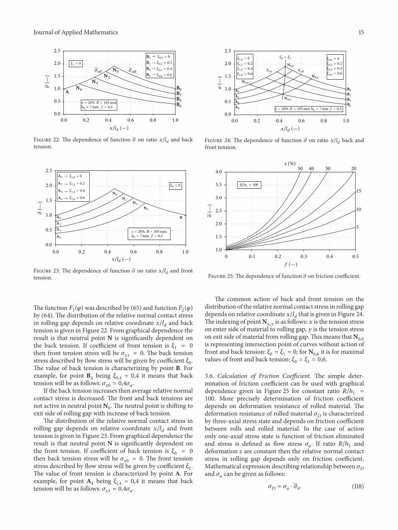