research article stability optimization of a disc brake system …downloads.hindawi.com › journals...
TRANSCRIPT

Research ArticleStability Optimization of a Disc Brake System withHybrid Uncertainties for Squeal Reduction
Hui Lü and Dejie Yu
State Key Laboratory of Advanced Design and Manufacturing for Vehicle Body, Hunan University, Changsha, Hunan 410082, China
Correspondence should be addressed to Dejie Yu; [email protected]
Received 2 November 2015; Revised 28 January 2016; Accepted 28 January 2016
Academic Editor: Tai Thai
Copyright © 2016 H. Lu and D. Yu. This is an open access article distributed under the Creative Commons Attribution License,which permits unrestricted use, distribution, and reproduction in any medium, provided the original work is properly cited.
A hybrid uncertain model is introduced to deal with the uncertainties existing in a disc brake system in this paper. By the hybriduncertain model, the uncertain parameters of the brake with enough sampling data are treated as probabilistic variables, while theuncertain parameters with limited data are treated as interval probabilistic variables whose distribution parameters are expressedas interval variables. Based on the hybrid uncertain model, the reliability-based design optimization (RBDO) of a disc brake withhybrid uncertainties is proposed to explore the optimal design for squeal reduction. In the optimization, the surrogate model ofthe real part of domain unstable eigenvalue of the brake system is established, and the upper bound of its expectation is adoptedas the optimization objective. The lower bounds of the functions related to system stability, the mass, and the stiffness of designcomponent are adopted as the optimization constraints. The combinational algorithm of Genetic Algorithm and Monte-Carlomethod is employed to perform the optimization.The results of a numerical example demonstrate the effectiveness of the proposedoptimization on improving system stability and reducing squeal propensity of a disc brake under hybrid uncertainties.
1. Introduction
Brake squeal is a noise problem caused by self-friction-induced vibrations which can induce dynamic instabilities ofbrake systems [1]. Poor stability performance of a disc brakesystem could lead to an inconvenient squealing noise. Thisfrequently leads to customer complaints and results in enor-mous warranty costs. Therefore, extensive efforts have beenundertaken by industrial corporations as well as by the sci-entific communities to resolve the squeal problem. Earlyresearches on brake squeal are mostly dedicated to the rootcauses of brake squeal and several representativemechanismshave been attributed to brake squeal phenomenon, such asstick-slip, sprag-slip, hammering, mode-coupling, and timedelay [2–5]. Moreover, several comprehensive review paperscan be found on the researches of brake squeal [6–10]. Ofthosemechanisms, themode-coupling has attracted themostattention in these literatures. However, the root cause of brakesqueal is still not fully understood due to its complexity.
The optimization designs of disc brake systems for squealreductionhave receivedmany researchers’ attentions recently.For example, Guan et al. [11] explored sensitivity analysis
methods to determine the dominantmodal parameters of thesubstructures of a brake system for squeal suppression, andthe dominantmodal parameters were set as the target of opti-mization design to seek the modifications of the disc and thebracket to eliminate the squeal mode. Spelsberg-Korspeter[12, 13] performed a structural optimization of brake rotorsto emphasize the potential of designing rotor geometryrobust against self-excited vibrations, and the mathematicaldifficulties of such an optimization were discussed. LakkamandKoetniyom [14] proposed an optimization study on brakesqueal aimed at minimizing the strain energy of vibratingpads with constrained layer damping; the results of thisresearch could be a guide to specify the position of the con-strained layer damping patch under pressure conditions.Shintani and Azegami [15] presented a solution to a nonpara-metric shape optimization problem of a disc brake modelto suppress squeal noise; the optimum shape of the pad wasfound and the real part of the complex eigenvalue represent-ing the cause of brake squeal was minimized.
The abovementioned studies on structural optimizationof disc brake systems are restricted to deterministic optimiza-tion, in which all design variables and parameters involved
Hindawi Publishing CorporationShock and VibrationVolume 2016, Article ID 3497468, 13 pageshttp://dx.doi.org/10.1155/2016/3497468

2 Shock and Vibration
are regarded certain. In practical engineering, uncertain fac-tors widely exist in the structures and systems, as well as in thebrake systems. Under uncertain cases, the optimum obtainedfrom a deterministic optimization could easily violate theconstraints and cause unreliable solutions and designs [16–18]. In order to take into account various uncertainties, theRBDO is introduced and has been intensively studied bothin the methodology and in applications [19–21]. Comparedwith the deterministic optimization, the RBDO aims to seek areliable optimum by converting the deterministic constraintsinto probabilistic constraints. Therefore, the RBDO can beconsidered as the potential method to improve the stabilityperformance of the uncertain disc brake systems for squealreduction.
Due to the effects of manufacturing errors, aggressiveenvironment factors, wear and unpredictable external exci-tations, uncertainties associated with material properties,geometric dimensions, and contact conditions are unavoid-able. On the investigation of disc brake squeal consideringuncertainties, just only a few research papers have been pub-lished at present. Chittepu [22] has carried out a robustnessevaluation of a brake systemwith a stochasticmodel, inwhichthe material scatter was modeled by random variables andthe geometrical tolerances were modeled by random fields.Based on the polynomial chaos expansions, the stochasticeigenvalue problems and the stability of a simplified discbrake have been investigated by Sarrouy et al. [23], in whichthe friction coefficient and the contact stiffness of the discbrake system were modeled as random parameters. Tison etal. [24] have proposed a complete strategy to improve theprediction of brake squeal by introducing uncertainty androbustness concepts into the simulations.The strategymainlyrelied on the integration of complex eigenvalue calculations,probabilistic analysis, and a robustness criterion. Lu and Yu[25, 26] have proposed practical approaches for the stabilityanalysis and optimization of disc brakes with probabilisticuncertainties or interval uncertainties for squeal reduction,in which an uncertain parameter is treated as either proba-bilistic variable or interval variable. It can be seen that theinvestigations on uncertain brake squeal problem are notstill comprehensive currently. It is necessary to develop moredifferent uncertain methods for the uncertain researches ondisc brake squeal reduction.
It is well known that probabilistic methods are thetraditional approach to cope with these uncertainties arisingin practical engineering problems, just as we can see in theabovementioned studies [22–24]. In the probabilistic meth-ods, the uncertain parameters are treated as probabilisticvariables whose probability distributions are defined unam-biguously [27]. To construct the precise probability distribu-tions of probabilistic variables, a large amount of statisticalinformation or experimental data is required. Unfortunately,in the design stage of a disc brake system, the informationto construct the precise probability distributions of someprobabilistic variables (e.g., the friction coefficient or thethicknesses of wearing components) is not always sufficientdue to the immeasurability or wear effects. In the last twodecades, the interval probabilistic model has been proposedfor overcoming the deficiencies of probabilistic methods. In
the interval probabilisticmodel, the uncertain parameters aretreated as interval probabilistic variables whose distributionparameters with limited information are expressed as intervalvariables instead of precise values. The interval probabilisticmodel was firstly proposed by Elishakoff et al. [28, 29] andsubsequently applied to the structural response analysis [30]and the structural reliability analysis [31]. From the overallperspective, researches on the interval probabilisticmodel arestill in the preliminary stage and some important issues arestill unsolved. For example, the application of the intervalprobabilistic model in the stability analysis of disc brakes isnot yet explored.
The purpose of this paper is to take into account thehybrid uncertainties existing in a disc brake and developan effective optimization for improving its system stabilityand suppressing its squeal propensity. For this purpose, aRBDO approach based on the hybrid uncertain model isproposed. In the hybrid uncertainmodel, the uncertainties ofthe thickness of nonwear component, the mass densities andelastic modulus of component materials, and the brake pres-sure are represented by using probabilistic variables, whosedistribution parameters are well defined, whereas the uncer-tainties of the friction coefficient, the thickness of disc, andfriction material are modeled by interval probabilistic vari-ables, whose distribution parameters are expressed as intervalvariables. To facilitate computation, the response surface (RS)model is used to replace the time-consuming FE simulations.Based on the methods of RSM, CEA, and hybrid uncertainanalysis, the RBDOmodel for improving the system stabilityof the disc brake is constructed. In the RBDO model, theupper bound of the expectation of the real part of the domainunstable eigenvalue is selected as design objective, while thelower bounds of the functions related to system stability, themass and the stiffness of design component, are adopted asoptimization constraints. The effectiveness of the proposedoptimization is demonstrated by a numerical example.
The rest of this paper is organized as follows: Section 2introduces the CEA of disc brakes; Section 3 describes theconstruction of the RBDO of a disc brake with hybrid uncer-tainties; Section 4 presents the procedure of the proposedRBDO; Section 5 provides a numerical example of the appli-cation of the proposed optimization, and finally Section 6draws the major conclusions.
2. Complex Eigenvalue Analysis of Disc Brake
2.1. A Simplified Disc Brake. For the purpose of simulatingthe vibration characteristics of a brake system reasonablywithan acceptable computation, a simplified disc brake system istaken for investigation.The simplified brake consists of a discand a pair of brake pads, as shown in Figure 1. The disc isrigidly mounted on the axle hub and therefore rotates withthe wheel. The pair of brake pad assemblies, which consist ofthe friction materials and the back plates, is pressed againstthe disc in order to generate a frictional torque to slow therotation of the disc. The similar simplified model has beenpreviously considered and successfully used by some studies,such as [23, 32–34].

Shock and Vibration 3
Brake disc
Friction material
Back plate
Brake pad
Figure 1: A simplified model of a disc brake system.
2.2. Complex Eigenvalue Analysis. The CEA can be carriedout by two stages. In the first stage, the steady state of thebrake system is found and in the second stage, the CEA isperformed.
In the steady state of the brake system, the vector ofapplied forces F(y, y) is balanced by the vector of nonlinearstiffness forces F𝑘(y). It can be expressed as
F𝑘 (y) = F (y, y) , (1)
where y is the steady-state displacement vector and y is thefirst derivative of y with respect to time. The nonlinearity ofstiffness forcesF𝑘(y) ismainly due to the contact formulation,in which the contact stiffness is commonly added at thedisc/pad interface.The disc is about one hundred times stifferthan the frictional material which is a mixture of manycomponents; thus deformation of a pad under loading ismuch greater and nonlinearity behavior occurs. For a morecomplete discussion of system nonlinearities, the readers canrefer to [35].
After the steady state of the system is found, in thesecond stage, the stability of system is assessed.The extendednonlinear equation of motion including the mass matrix Mand the damping matrixD is given by
My +Dy + F𝑘 (y) = F (y, y) , (2)
where y is the second derivative of y with respect to time.Thesystem can be linearized about the steady state
y = y0 + Δy, (3)
where y0 is the steady-state displacement vector and Δydenotes small perturbation in the vicinity of the steady state.After linearization, the resulting equation is given by
M ⋅ Δy +D ⋅ Δy + K ⋅ Δy = H1 ⋅ Δy +H0 ⋅ Δy, (4)
where matrices H0 and H1 are the partial derivatives ofF(y, y) with respect to the displacements and the velocities,respectively. Equation (4) can be simplified to
M ⋅ Δy + D ⋅ Δy + K ⋅ Δy = 0, (5)
where D and K are the new damping matrix and stiffnessmatrix; then the complex eigenvalue problem can be formu-lated as
(M𝜆2+ D𝜆 + K) 𝜙 = 0, (6)
where𝜆 is the complex eigenvalue and𝜙 is the complex eigen-mode.The complex eigenvalues of the system can be obtainedby solving the complex eigenvalue problem of (6). The 𝑖thcomplex eigenvalue 𝜆𝑖 can be expressed as
𝜆𝑖 = 𝛼𝑖 + 𝑗𝛽𝑖, (7)
where 𝛼𝑖 and 𝛽𝑖 are the real and imaginary parts of thecomplex eigenvalue 𝜆𝑖, respectively.
It is widely known that a vibration system will becomeunstable if the real part of a complex eigenvalue of the systemis positive.Therefore, the positive real parts of the eigenvaluescan be taken as an indicator for system stability and squealpropensity. The main aim of this study is to minimize thepositive real part of the dominant unstable eigenvalue of thebrake system.
It is worth mentioning that the damping is not taken intoaccount in the current study. Just as the recent study [36]points out, the damping models of friction materials or othercomponents have not been extensively studied at present andthere is no reliable data on the damping of brake systems.In most cases, the damping can stabilize brake systems andexcluding it will providemore potential unstable eigenvalues.Thus, industrial researchers tend to exclude the damping andset a target value for the real part or the damping ratio ofan unstable eigenvalue in CEA of practical engineering. Ifthe real part or the damping ratio is not larger than thetarget value, the brake system will be considered as stableand acceptable [36]. However, two main effects of dampingon coalescence patterns have been noticed in fact, namely,the shifting effect and the smoothing effect [37]. The first onealways stabilizes the brake, whereas the second onemay causeinstability. For more detailed and extensive discussion ofdamping on system stability, the readers can refer to [37].
Moreover, themain limitation of CEA is the use of a linearmodel which excludes dynamic contact. Sinou et al. [38, 39]pointed out that CEA may lead to underestimation or over-estimation of the unstable modes of a brake. In [38], it wasshown that additional unstable modes appeared during tran-sient oscillations, which were not predicted by CEA. Thus,the nonlinear methods have been proposed and developedto approximate the transient behavior in the time domain[40], or the limit cycle of frictional systems subjected to self-excited vibration and squeal noise in the frequency domain[41]. Besides, the stochastic studies have been recently carriedout to determine the limit cycles of a self-excited nonlinearsystem with friction which is commonly used to representbrake squeal phenomenon [42]. However, we mainly focusour attention on the stability analysis and optimization of alinear brake system with uncertainties in this work, consider-ing that CEA is a fast and efficient strategy for an industrialfinite element model. Therefore, just the CEA approach isused in this paper.
3. RBDO of the Disc Brake System withHybrid Uncertainties
3.1. Surrogate Model Based on RMS. In engineering design,the coupling of optimization algorithm with finite element

4 Shock and Vibration
analysis (FEA) may be inefficient, since the iterative analysesduring optimization usually require enormous iterations andhigh computational cost, especially for RBDO problem. Asa result, the surrogate models have been widely adoptedin engineering applications to alleviate the computationalburden. By surrogate models, the explicit mathematical rela-tionship between functional responses and design variablescan be established with a moderate number of FEA runs.RS model is one of the simplest and most popular surrogatemodels, which can be treated as an effective alternative to FEAand has been widely adopted in design optimization [43].
Mathematically, by the RS model, the real part of acomplex eigenvalue of FEA can be defined in terms of basisfunction as
𝛼 (x) =𝑁
∑𝑗=1
𝑎𝑗𝜑𝑗 (x) , (8)
where 𝛼(x) is the real part of a complex eigenvalue, 𝜑𝑗(x) arethe basis functions,𝑁 is the number of basis functions, and 𝑎𝑗represents the regression coefficients.Whenusing a quadraticmodel, the full set of the second-order polynomials of 𝜑𝑗(x)is given as
1, 𝑥1, 𝑥2, . . . , 𝑥𝑛, 𝑥2
1, 𝑥1𝑥2, . . . , 𝑥1𝑥𝑛, . . . , 𝑥
2
𝑛(9)
and the surrogate model of 𝛼(x) could be thus defined as
𝛼 (x) = 𝑎0 +𝑛
∑𝑖=1
𝑎𝑖𝑥𝑖 + ∑𝑖𝑗(𝑖<𝑗)
𝑎𝑖𝑗𝑥𝑖𝑥𝑗 +
𝑛
∑𝑖=1
𝑎𝑖𝑖𝑥2
𝑖, (10)
where x = [𝑥1, 𝑥2, . . . , 𝑥𝑛]𝑇 denotes the variable vector that
determines the response 𝛼(x) and 𝑎0, 𝑎𝑖, 𝑎𝑖𝑗, and 𝑎𝑖𝑖 are theestimated regression coefficients which can be obtained fromthe design of experiment (DOE) and by the least squaremethod (LSM) [44]. The cross product terms 𝑥𝑖𝑥𝑗 representthe two-variable interactions and the square terms 𝑥2
𝑖repre-
sent the second-order nonlinearities. 𝑛 is the number of thevariables.
After the RS model is established, its accuracy should beassessed. It is necessary to conduct an analysis of variance(ANOVA) to test themodel, so as to ensure its fitting accuracyand significance [45].
It is worth mentioning that the surrogate model withkriging predictor has been recently proposed to investigatethe propensity of brake squeal by Nobari et al. [36] andNechak et al. [46]. However, the current study is not focusedon the surrogate models; thus just the most widely used sur-rogate model (RS model) is applied here. Indeed, it has greatsignificance to carry out further studies on the application ofdifferent surrogate models to squeal problem in the future.
3.2. Disc Brake System with Hybrid Uncertainties. Due to thecomplex working environment and operating conditions, theoccurrence of brake squeal is intermittent or perhaps evencasual in general, and it is difficult to be captured and repro-duced artificially. This is possibly related to the uncertaintiesexisting in the brake system. For instance, the friction coeffi-cient is changed in the course of braking. This characteristic
of friction coefficient makes it possible to provide the energysource for brake squeal [9]. So it will be more reasonable andbe of great significance, if the uncertainties are taken intoaccount for the stability analysis of the disc brake systems.
For the disc brake system, uncertainties in material, geo-metry, and loading properties and manufacturing errors areunavoidable. Usually, the most common approach to modelthe uncertainties is the probabilistic model. By this approach,𝛼(x) in (10) for an uncertain optimization problem can begenerally expressed as
𝛼 (x) = 𝛼 (x𝐷, x𝑃) , (11)
where x𝐷 = [𝑥𝐷,1, 𝑥𝐷,2, . . . , 𝑥𝐷,𝑘]𝑇 is the design variable
vector and 𝑘 is the number of design variables; x𝑃 =
[𝑥𝑃,1, 𝑥𝑃,2, . . . , 𝑥𝑃,𝑙]𝑇 is the probabilistic variable vector which
is taken as nondesign variables and 𝑙 is the number ofprobabilistic variables.
In the real case, the disc brake is a rather complex systemwhich is related to frictional contact and wear [47]. It isdifficult or even impossible to obtain the precise values of thedistribution parameters of some probabilistic variables, suchas the friction coefficient and the thickness of wearing com-ponents. In order tomodel the uncertainties of these parame-ters more properly, these uncertain parameters are treated asinterval probabilistic variables whose distribution parametersare expressed as interval variables rather than unique valuesin this study. In this case,𝛼(x) in (11) then becomes an intervalprobabilistic objective function for a hybrid uncertain opti-mization problem and can be expressed as
𝛼 (x) = 𝛼 (x𝐷, x𝑃) = 𝛼 (x𝐷, x𝑃1, x𝑃2) , (12)
where x𝑃1 = [𝑥𝑃1,1, 𝑥𝑃1,2, . . . , 𝑥𝑃1,𝑙−𝑚]𝑇 is the probabilistic
variable vector of the hybrid uncertain problem and 𝑙 − 𝑚 isthe number of probabilistic variables. x𝑃2 = [𝑥𝑃2,1, 𝑥𝑃2,2, . . . ,
𝑥𝑃2,𝑚]𝑇 is the interval probabilistic variables vector of the
hybrid uncertain problem, and 𝑚 is the number of intervalprobabilistic variables.
Due to the manufacturing or measuring errors, theactual values of the design variable x𝐷 may deviate fromtheir theoretical values in engineering practice. In this case,the design variables x𝐷 can be treated as the probabilisticvariables as well.
3.3. RBDO of the Disc Brake SystemwithHybrid Uncertainties.The RBDO model of the disc brake system with hybriduncertainties can be generally expressed as
minx𝐷𝛼 (x) = 𝛼 (x𝐷, x𝑃1, x𝑃2)
s.t. 𝑃 (𝑔𝑟 (x𝐷, x𝑃1, x𝑃2) ≥ 0) ≥ 𝜂𝑟, 𝑟 = 1, 2, . . . , 𝑡
x𝐷,lower ≤ x𝐷 ≤ x𝐷,upper,
(13)
where 𝛼(x𝐷, x𝑃1, x𝑃2) is the interval probabilistic objectivefunction. 𝑔𝑟(x𝐷, x𝑃1, x𝑃2) is the 𝑟th limit-state function, and 𝑡is the number of limit-state functions. 𝑔𝑟(x𝐷, x𝑃1, x𝑃2) = 0 isthe limit-state equation by which the designspace is divided

Shock and Vibration 5
into the safe region 𝑔𝑟(x𝐷, x𝑃1, x𝑃2) > 0 and the failure region𝑔𝑟(x𝐷, x𝑃1, x𝑃2) < 0. 𝑃(𝑔𝑟(x𝐷, x𝑃1, x𝑃2) ≥ 0) is the probabilityfor 𝑔𝑟(x𝐷, x𝑃1, x𝑃2) ≥ 0. 𝜂𝑟 is the 𝑟th system reliability indexwhich is close to 1 with the increase of required reliabilitylevel.
The objective function 𝛼(x𝐷, x𝑃1, x𝑃2) is an interval prob-abilistic function. Without considering the interval variablesexisting in the interval probabilistic variables x𝑃2 temporarily,the objective function 𝛼(x𝐷, x𝑃1, x𝑃2) can be treated as a pureprobabilistic function. The probabilistic characteristic of thevalues of 𝛼(x𝐷, x𝑃1, x𝑃2) can be expressed as the expectationof 𝛼(x𝐷, x𝑃1, x𝑃2).Therefore, the purpose of the RBDOmodelcan be expressed as
minx𝐷𝜇 (𝛼 (x𝐷, x𝑃1, x𝑃2)) , (14)
where 𝜇(𝛼(x𝐷, x𝑃1, x𝑃2)) is the expectation of 𝛼(x𝐷, x𝑃1, x𝑃2).As the interval variables exist in x𝑃2 actually, the obtained
expectation 𝜇(𝛼(x𝐷, x𝑃1, x𝑃2)) is a function of interval vari-ables. 𝜇(𝛼(x𝐷, x𝑃1, x𝑃2)) is uncertain suffering from intervalvariables. For the disc brake system, the optimization goal isto reduce 𝜇(𝛼(x𝐷, x𝑃1, x𝑃2)) to improve system stability. Con-sequently, if the maximal value of 𝜇(𝛼(x𝐷, x𝑃1, x𝑃2)) (markedas 𝜇(𝛼(x𝐷, x𝑃1, x𝑃2))upper) satisfies the design requirements,the other values (which are no more than the maximal value)of 𝜇(𝛼(x𝐷, x𝑃1, x𝑃2))will also satisfy the design requirements.As a result, the maximal value of 𝜇(𝛼(x𝐷, x𝑃1, x𝑃2)) can beselected as the optimization objective.
Therefore, the purpose of the RBDO of the disc brakesystem with hybrid uncertainties for squeal reduction can beexpressed as
minx𝐷𝜇 (𝛼 (x𝐷, x𝑃1, x𝑃2))upper , (15)
where 𝜇(𝛼(x𝐷, x𝑃1, x𝑃2))upper is the upper bound of 𝜇(𝛼(x𝐷,x𝑃1, x𝑃2)).
Without considering the interval variables existing ininterval probabilistic variables x𝑃2 temporarily, the 𝑟th limit-state function 𝑔𝑟(x𝐷, x𝑃1, x𝑃2) can be treated as a pureprobabilistic function.The probability of 𝑔𝑟(x𝐷, x𝑃1, x𝑃2) ≥ 0,namely, 𝑃(𝑔𝑟(x𝐷, x𝑃1, x𝑃2) ≥ 0), is a deterministic value. Asthe interval variables exist in x𝑃2 actually,𝑃(𝑔𝑟(x𝐷, x𝑃1, x𝑃2) ≥0) is a function of interval variables. 𝑃(𝑔𝑟(x𝐷, x𝑃1, x𝑃2) ≥
0) is uncertain suffering from interval variables, and theuncertainty of 𝑃(𝑔𝑟(x𝐷, x𝑃1, x𝑃2) ≥ 0) can be describedby the variational range of 𝑃(𝑔𝑟(x𝐷, x𝑃1, x𝑃2) ≥ 0). Ifthe lower bound of 𝑃(𝑔𝑟(x𝐷, x𝑃1, x𝑃2) ≥ 0) (marked as𝑃(𝑔𝑟(x𝐷, x𝑃1, x𝑃2) ≥ 0)lower) is larger than 𝜂𝑟, the other valuesof 𝑃(𝑔𝑟(x𝐷, x𝑃1, x𝑃2) ≥ 0) within the variational range willbe also larger than 𝜂𝑟. Thus, the constraint conditions can berewritten as
𝑃 (𝑔𝑟 (x𝐷, x𝑃1, x𝑃2) ≥ 0)lower ≥ 𝜂𝑟, 𝑟 = 1, 2, . . . , 𝑡, (16)
where 𝑃(𝑔𝑟(x𝐷, x𝑃1, x𝑃2) ≥ 0)lower is the lower bound of𝑃(𝑔𝑟(x𝐷, x𝑃1, x𝑃2) ≥ 0).
Based on the discussion above, the RBDO of the discbrake system with hybrid uncertainties for squeal reductioncan be expressed as
minx𝐷𝜇 (𝛼 (x𝐷, x𝑃1, x𝑃2))upper
s.t. 𝑃 (𝑔𝑟 (x𝐷, x𝑃1, x𝑃2) ≥ 0)lower ≥ 𝜂𝑟,
𝑟 = 1, 2, . . . , 𝑡,
x𝐷,lower ≤ x𝐷 ≤ x𝐷,upper.
(17)
3.4. Calculations of the Objective Function and ConstraintFunction. Based on the clear expression of the RS model𝛼(x), the Monte-Carlo method can be considered as a poten-tial method to calculate the objective function 𝜇(𝛼(x𝐷, x𝑃1,x𝑃2))upper and the constraint function 𝑃(𝑔𝑟(x𝐷, x𝑃1, x𝑃2) ≥
0)lower. The main procedures of the calculations based onMonte-Carlo method can be described in the following.
Step 1. Generate 𝑖th (𝑖 = 1, 2, . . . , 𝑁𝑖) sample of the intervalvariables existing in the interval probabilistic variable vectorx𝑃2. Then x𝑃2 degenerated to the probabilistic variable vectorwith the sample values of the interval variables and can bemarked as probabilistic variable vector x(𝑖)
𝑃2.
Step 2. Generate 𝑗th (𝑗 = 1, 2, . . . , 𝑁𝑗) sample of the prob-abilistic variable vectors x𝑃1 and x(𝑖)
𝑃2. Then x𝑃1 and x(𝑖)
𝑃2
degenerated to the deterministic value vector with the samplevalues of the probabilistic variables and can be marked as x(𝑗)
𝑃1
and x(𝑖,𝑗)𝑃2
.
Step 3. Calculate the values of 𝛼(x𝐷, x𝑃1, x𝑃2)(𝑖,𝑗)
= 𝛼(x𝐷, x(𝑗)
𝑃1,
x(𝑖,𝑗)𝑃2
) and 𝑔𝑟(𝛼(x𝐷, x𝑃1, x𝑃2))(𝑖,𝑗)
= 𝑔𝑟(𝛼(x𝐷, x(𝑗)
𝑃1, x(𝑖,𝑗)𝑃2
)).
Step 4. Has the sampling of x𝑃1 and x(𝑖)𝑃2
ended? Namely,does 𝑗 equate to 𝑁𝑗 (the number of samples of probabilisticvariable vectors)? If no, 𝑗 = 𝑗 + 1 and go on to Step 2.If yes, calculate the expectation 𝜇(𝛼(x𝐷, x𝑃1, x𝑃2))
(𝑖) and theprobability 𝑃(𝑔𝑟(x𝐷, x𝑃1, x𝑃2) ≥ 0)
(𝑖) based on all values of𝛼(x𝐷, x𝑃1, x𝑃2)
(𝑖,𝑗) and 𝑔𝑟(𝛼(x𝐷, x𝑃1, x𝑃2))(𝑖,𝑗), 𝑗 = 1, 2, . . . , 𝑁𝑗,
and export them.
Step 5. Has the sampling of interval variables existing in x𝑃2ended? Namely, does 𝑖 equate to 𝑁𝑖 (the number of samplesof interval variable vector)? If no, 𝑖 = 𝑖 + 1 and go on toStep 1. If yes, select 𝜇(𝛼(x𝐷, x𝑃1, x𝑃2))upper and 𝑃(𝑔𝑟(x𝐷, x𝑃1,x𝑃2) ≥ 0)lower from all values of 𝜇(𝛼(x𝐷, x𝑃1, x𝑃2))
(𝑖) and𝑃(𝑔𝑟(x𝐷, x𝑃1, x𝑃2) ≥ 0)
(𝑖), 𝑖 = 1, 2, . . . , 𝑁𝑖, and export them.
Theprocedure can be summarized in the flowchart shownin Figure 2.

6 Shock and Vibration
Mathematic model of
Start
End
Yes
No
No
Yes
𝛼(xD, xP1, xP2) and gr(xD, xP1, xP2)
Generate sample of the interval variables that existed in xP2
Generate sample of probabilistic variable vectors xP1 and x(i)P2
Calculate 𝛼(xD, xP1, xP2)(i,j) and gr(xD, xP1, xP2)(i,j)
Calculate 𝜇(𝛼(xD, xP1, xP2))(i) and P(gr(xD, xP1, xP2) ≥ 0)(i)
Select 𝜇(𝛼(xD, xP1, xP2))upper and P(gr(xD, xP1, xP2) ≥ 0)lower, and export them
Does j equate to Nj
Does i equate to Ni
?
?
Figure 2: Flowchart of the calculation of objective function and constraint function.
4. The Procedure of the RBDO of the DiscBrake System with Hybrid Uncertainties forSqueal Reduction
Based on Sections 2 and 3, the main procedure of the RBDOof the disc brake system with hybrid uncertainties for squealreduction can be summarized as follows.
Step 1. Construct the mathematic model of the RBDO(shown in (17)) for the disc brake system with hybrid uncer-tainties, based on CEA (shown in (6)) and RSM (shown in(10)).
Step 2. Initialize the design variables x𝐷.
Step 3. Estimate the objective function 𝜇(𝛼(x𝐷, x𝑃1, x𝑃2))upperand the constrain function 𝑃(𝑔𝑟(x𝐷, x𝑃1, x𝑃2) ≥ 0)lower basedon Monte-Carlo method.
Step 4. Is the end condition of the optimization algorithmmet? If no, update the design variables and go back to Step3. If yes, output the optimal design.
The flowchart of the optimization is given in Figure 3.
5. Numerical Example
5.1. FEModel of a Simplified Brake. In this section, the simpli-fied disc brake shown in Figure 1 is adopted for investigationand its FE model is shown in Figure 4. The disc is made ofgrey cast iron which is wear resistant and relatively inexpen-sive. The friction material is made of anisotropic compositematerials and it is mounted to the rigid brake plate which ismade of steel.
The FE model is generated by using the three-dimen-sional continuum elements and the fine meshes are used inthe contact areas.The FEmodel includes 24653 elements and35685 nodes and the element types are C3D8I and C3D6.The friction contact interactions are defined in the contactsurfaces of the pads and the disc. The contact formulationsof the pads-to-disc interfaces are “surface-to-surface, small-sliding” with friction and penalty method.The friction at thecontact interfaces follows the principle of the Coulomb fric-tion and the contacts follow the principle of hard contacts.The friction and contact formulations in ABAQUS/Standardhave been extensively discussed in [23, 32, 36].
For the constraints and loadings, the disc is rigidly con-strained at its five bolt holes and the MOTION card is usedto rotate the disc. For the brake pad assemblies, the leadingedges are rigidly constrained in the radial direction of the disc

Shock and Vibration 7
Table 1: The initial values and the ranges of the investigated parameters.
Parameter Unit Initial value RangeLower Upper
Density of back plate 𝜌1 kg/dm3 7.82 6.50 9.00Elastic modulus of back plate 𝐸1 GPa 207 180 230Thickness of back plate 𝑑1 mm 6.20 5.00 7.50Density of friction material 𝜌2 kg/dm3 2.51 2.259 2.761Elastic modulus of friction material 𝐸2 GPa 5.94 4.752 7.128Thickness of friction material 𝑑2 mm 12.0 8.5 12.5Density of disc 𝜌3 kg/dm3 7.20 6.48 7.92Elastic modulus of disc 𝐸3 GPa 125 112.5 137.5Thickness of disc 𝑑3 mm 20 18.5 20.5Brake pressure 𝑝 MPa 0.5 0.45 0.55Friction coefficient 𝑓 — 0.32 0.26 0.38
Mathematic model of RBDO
Initialize the design variables
The end condition is met?
Start
End
Yes
No
Update the design variables
Output the optimal design.
xD = xD0
Estimate 𝜇(𝛼(xD, xP1, xP2))upper and
P(gr(xD, xP1, xP2) ≤ 0)lower
Figure 3: Flowchart of the proposed RBDOof the disc brake systemwith hybrid uncertainties.
while the trailing edges are constrained both at the circum-ferential and at the radial directions of the disc. The brakepressure is directly applied to the back plates at the contactregion between the inner pad and the piston and the contactregion between the outer pad and the caliper. It is assumedthat an equal magnitude of force acts on each pad assembly.
The main procedure of CEA based on the current FEmodel contains the following steps: (1) static analysis for theapplication of brake pressure (0.5MPa); (2) static analysisto impose the disc’s rotational velocity (5 rad/s); (3) normalmode analysis to extract the natural frequency to determinethe projection subspace; and (4) complex eigenvalue analysisusing the subspace projection method.
Figure 4: The FEMmodel of a simplified disc brake.
Slot
Back plate
Friction material
Figure 5: The slot of the friction material.
For this commercial brake system, some common andeffective measures have been taken to reduce the likelihoodof squeal in the early design phase. For example, a slot hasbeen provided in the middle position of the friction materialas shown in Figure 5. Therefore, the original stability of thisbrake is relatively high.
This study aims to optimize the real part of the dominantunstable eigenvalue for reducing potential squeal. The eigen-value analysis is dependent on a number of factors, such as thestiffness andmass characteristics and operating conditions ofthe system. Base upon this, the system parameters that weselect to investigate are listed in Table 1.The initial values andthe variational ranges of the investigated parameters are alsolisted in Table 1.
In addition, it should be specially pointed out that anassumption of the elastic property for the friction materialhas beenmade. For this brake, the frictionmaterial ismade oforganic material and has anisotropic properties. Referring tosome earlier works, for instance, the studies of Junior et al.[34] and Cao et al. [48], we treat the friction material as

8 Shock and Vibration
2000 4000 6000 8000 10000 12000 14000 160000Imaginary part 𝛽 (Hz)
−100
−50
0
50
100
Real
par
t𝛼
Figure 6: The distribution of the complex eigenvalues of the brakesystem for some samples.
isotropic material but with varied elastic modulus in thisresearch.This assumption can be acceptable in an uncertaintyanalysis.
5.2. DOE and Determination of Dominant Unstable Eigen-value. Latin Hypercube Sampling (LHS) method [49] isadopted for DOE, and a total of 120 samples are generatedin the design space, which is built up by the parametervariational ranges shown in Table 1. For each sample, CEAis performed in a personal computer based upon (6) and theFE model of the brake. The eigenvalue analysis is carried outin the frequency range of 0–16 kHz where the brake squealcommonly occurs.The analysis results show that the unstableeigenvalues mainly appear around the frequency of 2 kHz inthis research. Based on some earlier works, such as the studiesof AbuBakar and Ouyang [32] and Nouby et al. [50], we takethe unstable eigenvalues at the certain frequency for studying.Therefore, the unstable eigenvalue at 2 kHz for each sampleis regarded as the dominant unstable eigenvalue whose realpart is positive and is needed to be reduced to improve systemstability.
For a clearer understanding, some samples are selectedarbitrarily from the 120 samples for investigation, and thecomplex eigenvalues of the brake system corresponding tothese samples are depicted in Figure 6. In the figure, the samemarkers represent the complex eigenvalues of the systemunder the same sample. It can be seen that the major unstablefrequency is approximately 2 kHz.
5.3. Construction of RS Model. Based on the LSM approachand the CEA results of the 120 samples, the RS model of thereal part of the dominant unstable eigenvalue is constructedas follows according to (10):
𝛼 (x) = 𝛼 (𝜌1, 𝐸1, 𝑑1, 𝜌2, 𝐸2, 𝑑2, 𝜌3, 𝐸3, 𝑑3, 𝑝, 𝑓)
= −4173.446 + 176.689𝜌1 − 3.495𝐸1 − 17.510𝑑1
+ 379.791𝜌2 + 97.618𝐸2 + 190.453𝑑2
+ 67.872𝜌3 − 8.742𝐸3 + 363.090𝑑3
− 3708.734𝑝 − 1801.577𝑓 + 0.215𝜌1𝐸1
+ 2.271𝜌1𝑑1 − 14.639𝜌1𝜌2 − 4.331𝜌1𝐸2
− 3.573𝜌1𝑑2 + 7.718𝜌1𝜌3 − 0.441𝜌1𝐸3
− 8.088𝜌1𝑑3 + 138.437𝜌1𝑝 + 90.628𝜌1𝑓
− 0.189𝐸1𝑑1 + 0.333𝐸1𝜌2 + 0.036𝐸1𝐸2
+ 0.004𝐸1𝑑2 − 0.333𝐸1𝜌3 + 0.014𝐸1𝐸3
− 0.246𝐸1𝑑3 + 3.521𝐸1𝑝 + 4.897𝐸1𝑓
− 4.135𝑑1𝜌2 + 7.706𝑑1𝐸2 − 1.627𝑑1𝑑2
− 6.547𝑑1𝜌3 + 0.087𝑑1𝐸3 + 4.281𝑑1𝑑3
− 113.832𝑑1𝑝 − 56.802𝑑1𝑓 − 5.779𝜌2𝐸2
− 11.839𝜌2𝑑2 − 16.931𝜌2𝜌3 + 1.285𝜌2𝐸3
− 21.037𝜌2𝑑3 + 206.002𝜌2𝑝 + 191.034𝜌2𝑓
− 0.562𝐸2𝑑2 + 2.141𝐸2𝜌3 − 0.365𝐸2𝐸3
− 2.088𝐸2𝑑3 − 48.563𝐸2𝑝 − 29.144𝐸2𝑓
+ 0.682𝑑2𝜌3 − 0.143𝑑2𝐸3 − 4.198𝑑2𝑑3
+ 18.731𝑑2𝑝 − 3.496𝑑2𝑓 + 0.415𝜌3𝐸3
+ 4.098𝜌3𝑑3 − 102.687𝜌3𝑝 + 30.748𝜌3𝑓
+ 0.249𝐸3𝑑3 + 3.491𝐸3𝑝 − 0.922𝐸3𝑓
− 6.233𝑑3𝑝 − 54.917𝑑3𝑓 + 2384.332𝑝𝑓
− 3.479𝜌2
1+ 0.009𝐸
2
1+ 3.267𝑑
2
1+ 14.705𝜌
2
2
+ 0.475𝐸2
2− 0.959𝑑
2
2− 8.346𝜌
2
3+ 0.004𝐸
2
3
− 5.056𝑑2
3+ 1797.920𝑝
2+ 376.181𝑓
2,
(18)
where x = [𝜌1, 𝐸1, 𝑑1, 𝜌2, 𝐸2, 𝑑2, 𝜌3, 𝐸3, 𝑑3, 𝑝, 𝑓]𝑇 is the vector
of investigated parameters and 𝛼(x) is the real part of thedominant unstable eigenvalue.
It is critical to validate the significance and adequacy ofthe RS model 𝛼(x). For this purpose, ANOVA is carried outand the analysis results are shown in Table 2.
The coefficient of determination (𝑅2) is defined as theratio of the explained variable to the total variation. It is ameasurement of the degree of fitness. When 𝑅2 is close to 1,the model fits the actual experimental data better. The sug-gested 𝑅2 value should be at least 0.80 for a good fit of amodel [51]. It can be seen from Table 2 that the 𝑅2 value of𝛼(x) is higher than 0.80, which indicates that 𝛼(x) can explainthe observed response well. While the 𝑝 value is lower than0.01, it indicates that themodel is considered to be statisticallysignificant [49]. It can be seen fromTable 2 that the RSmodelis highly significant, as the 𝑝 value of the model is less than0.0001.
Hence, the RS model 𝛼(x) is successful in describing thecorrelation between the system parameters and the systemresponse.

Shock and Vibration 9
Table 2: ANOVA results for the RS model 𝛼(x).
Source Sum of squares Degree of freedom Mean square 𝐹 value 𝑝 valueRegression 1.028e5 77 1335.03 39.68 <0.0001Residuals 1412.95 42 33.64Total 1.042e5 119
𝑅 = 0.9932 𝑅2= 0.9864
Table 3: The probability distributions of probabilistic variables.
Probabilistic variable Unit Distribution type Distribution parametersExpectation 𝜇 Standard deviation 𝜎
Density of friction material 𝜌2 kg/dm3 Normal 2.51 0.04Elastic modulus of friction material 𝐸2 GPa Normal 5.94 0.09Density of disc 𝜌3 kg/dm3 Normal 7.2 0.10Elastic modulus of disc 𝐸
3GPa Normal 125 2.0
Brake pressure 𝑝 MPa Normal 0.5 0.008
Table 4: The probability distributions of interval probabilistic variables.
Interval probabilistic parameter Unit Distribution type Distribution parametersExpectation 𝜇 Standard deviation 𝜎
Thickness of friction material 𝑑2
mm Normal [9, 12] 0.1Thickness of disc 𝑑3 mm Normal [19, 20] 0.1Friction coefficient 𝑓 — Normal [0.28, 0.36] 0.005
5.4. Uncertainties Existing in the Disc Brake. In practice,uncertainties in material properties, geometry properties,and loading properties are unavoidable. Uncertainties widelyexist in a real disc brake system as well. In order to modelthe uncertainties of the disc brake system more accurately,the uncertain parameters of the brake system with enoughinformation to construct the precise probability distributionsare treated as probabilistic variables, while the uncertainparameters with limited data are treated as interval proba-bilistic variables. Namely, the uncertain variables of the discbrake system are divided into probabilistic variables x𝑃1 andinterval probabilistic variables x𝑃2.
According to the engineering practice, the density andthe elastic modulus of the friction material, the densityand the elastic modulus of the disc, and the brake pressureare considered as probabilistic variables; namely, x𝑃1 =
[𝜌2, 𝐸2, 𝜌3, 𝐸3, 𝑝]𝑇.Their probability distributions are listed in
Table 3.The disc brake system is a complex system related to
frictional contact and wear. In the process of braking, thefriction coefficient is changed with respect to the slidingvelocity between the pad and disc, and the thicknesses of fric-tion material and disc decreases continuously due to wear.Therefore, it is difficult or even impossible to obtain theprecise values of the probability distribution parameters ofthe friction coefficient, the thickness of friction material,and the thickness of disc. As a consequence, these uncertainparameters are assumed as interval probabilistic variables,namely, x𝑃2 = [𝑑2, 𝑑3, 𝑓]
𝑇. Their probability distributions arelisted in Table 4.
5.5. The RBDO of the Disc Brake with Hybrid Uncertainties.The back plate of the brake is considered as the design com-ponent and its density, elasticmodulus, and thickness param-eters are taken as the design variables; namely, x𝐷 = [𝜌1, 𝐸1,
𝑑1]𝑇. Due to the manufacturing errors, the actual values
of these design variables may deviate from their theoreticalvalues in engineering practice. In this case, 𝜌1, 𝐸1, and 𝑑1 arealso treated as probabilistic variables which are assumed tofollow normal distributions, and their expectations (markedas𝜇𝜌1 ,𝜇𝐸1 , and𝜇𝑑1) are taken as design parameters while theirstandard deviations (marked as 𝜎𝜌1 , 𝜎𝐸1 , and 𝜎𝑑1) are takenas deterministic values. In this research, the design rangesof 𝜇𝜌1 , 𝜇𝐸1 , and 𝜇𝑑1 are considered as 7.0 kg/dm3 ≤ 𝜇𝜌1 ≤
8.5 kg/dm3, 190GPa ≤ 𝜇𝐸1 ≤ 220GPa, and 5.5mm ≤ 𝜇𝑑1 ≤
7.0mm, respectively. The standard deviations of 𝜇𝜌1 , 𝜇𝐸1 , and𝜇𝑑1 are considered as 𝜎𝜌1 = 0.1 kg/dm3, 𝜎𝐸1 = 3.0GPa, and𝜎𝑑1 = 0.1mm, respectively.
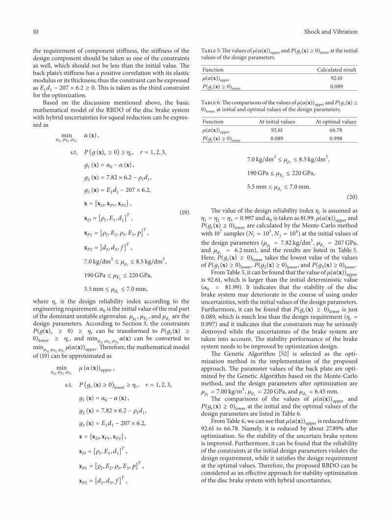
As is well known, the new brake is usually very stable andthe squeal phenomenon commonly occurs in the middle andlater stages of using. In order to guarantee the system stability,𝛼(x) should not be larger than the initial deterministic value(𝛼0 = 81.99), which can be obtained by the FEA orapproximately calculated by the RSmodel. It can be expressedas 𝛼0 − 𝛼(x) ≥ 0. This is taken as one of the constraints forthe optimization problem. For lightweight requirement, themass of the design component should not be larger than theinitial value; it can be expressed as 7.82 × 6.2 − 𝜌1𝑑1 ≥ 0. Thisis taken as the second constraint for the optimization. For
10 Shock and Vibration
the requirement of component stiffness, the stiffness of thedesign component should be taken as one of the constraintsas well, which should not be less than the initial value. Theback plate’s stiffness has a positive correlation with its elasticmodulus or its thickness; thus the constraint can be expressedas 𝐸1𝑑1 − 207 × 6.2 ≥ 0. This is taken as the third constraintfor the optimization.
Based on the discussion mentioned above, the basicmathematical model of the RBDO of the disc brake systemwith hybrid uncertainties for squeal reduction can be expres-sed as
min𝜇𝜌1,𝜇𝐸1,𝜇𝑑1
𝛼 (x) ,
s.t. 𝑃 (𝑔 (x)𝑟 ≥ 0) ≥ 𝜂𝑟, 𝑟 = 1, 2, 3,
𝑔1 (x) = 𝛼0 − 𝛼 (x) ,
𝑔2 (x) = 7.82 × 6.2 − 𝜌1𝑑1,
𝑔3 (x) = 𝐸1𝑑1 − 207 × 6.2,
x = {x𝐷, x𝑃1, x𝑃2} ,
x𝐷 = [𝜌1, 𝐸1, 𝑑1]𝑇,
x𝑃1 = [𝜌2, 𝐸2, 𝜌3, 𝐸3, 𝑝]𝑇,
x𝑃2 = [𝑑2, 𝑑3, 𝑓]𝑇,
7.0 kg/dm3 ≤ 𝜇𝜌1 ≤ 8.5 kg/dm3,
190GPa ≤ 𝜇𝐸1 ≤ 220GPa,
5.5mm ≤ 𝜇𝑑1 ≤ 7.0mm,
(19)
where 𝜂𝑟 is the design reliability index according to theengineering requirement.𝛼0 is the initial value of the real partof the dominant unstable eigenvalue. 𝜇𝜌1 , 𝜇𝐸1 , and 𝜇𝑑1 are thedesign parameters. According to Section 3, the constraints𝑃(𝑔(x)𝑟 ≥ 0) ≥ 𝜂𝑟 can be transformed to 𝑃(𝑔𝑟(x) ≥
0)lower ≥ 𝜂𝑟, and min𝜇𝜌1 ,𝜇𝐸1 ,𝜇𝑑1𝛼(x) can be converted tomin𝜇𝜌1 ,𝜇𝐸1 ,𝜇𝑑1𝜇(𝛼(x))upper. Therefore, the mathematical modelof (19) can be approximated as
min𝜇𝜌1,𝜇𝐸1,𝜇𝑑1
𝜇 (𝛼 (x))upper ,
s.t. 𝑃 (𝑔𝑟 (x) ≥ 0)lower ≥ 𝜂𝑟, 𝑟 = 1, 2, 3,
𝑔1 (x) = 𝛼0 − 𝛼 (x) ,
𝑔2 (x) = 7.82 × 6.2 − 𝜌1𝑑1,
𝑔3 (x) = 𝐸1𝑑1 − 207 × 6.2,
x = {x𝐷, x𝑃1, x𝑃2} ,
x𝐷 = [𝜌1, 𝐸1, 𝑑1]𝑇,
x𝑃1 = [𝜌2, 𝐸2, 𝜌3, 𝐸3, 𝑝]𝑇,
x𝑃2 = [𝑑2, 𝑑3, 𝑓]𝑇,
Table 5:The values of 𝜇(𝛼(x))upper and𝑃(𝑔𝑟(x) ≥ 0)lower at the initialvalues of the design parameters.
Function Calculated result𝜇(𝛼(x))upper 92.61𝑃(𝑔𝑟(x) ≥ 0)lower 0.089
Table 6:The comparisons of the values of𝜇(𝛼(x))upper and𝑃(𝑔𝑟(x) ≥0)lower at initial and optimal values of the design parameters.
Function At initial values At optimal values𝜇(𝛼(x))upper 92.61 66.78𝑃(𝑔𝑟(x) ≥ 0)lower 0.089 0.998
7.0 kg/dm3 ≤ 𝜇𝜌1 ≤ 8.5 kg/dm3,
190GPa ≤ 𝜇𝐸1 ≤ 220GPa,
5.5mm ≤ 𝜇𝑑1 ≤ 7.0mm.(20)
The value of the design reliability index 𝜂𝑟 is assumed as𝜂1 = 𝜂2 = 𝜂3 = 0.997 and 𝛼0 is taken as 81.99. 𝜇(𝛼(x))upper and𝑃(𝑔𝑟(x) ≥ 0)lower are calculated by the Monte-Carlo methodwith 107 samples (𝑁𝑖 = 103, 𝑁𝑗 = 104) at the initial values ofthe design parameters (𝜇𝜌1 = 7.82 kg/dm3, 𝜇𝐸1 = 207GPa,and 𝜇𝑑1 = 6.2mm), and the results are listed in Table 5.Here, 𝑃(𝑔𝑟(x) ≥ 0)lower takes the lowest value of the valuesof 𝑃(𝑔1(x) ≥ 0)lower, 𝑃(𝑔2(x) ≥ 0)lower, and 𝑃(𝑔3(x) ≥ 0)lower.
FromTable 5, it can be found that the value of𝜇(𝛼(x))upperis 92.61, which is larger than the initial deterministic value(𝛼0 = 81.99). It indicates that the stability of the discbrake system may deteriorate in the course of using underuncertainties, with the initial values of the design parameters.Furthermore, it can be found that 𝑃(𝑔𝑟(x) ≥ 0)lower is just0.089, which is much less than the design requirement (𝜂𝑟 =0.997) and it indicates that the constraints may be seriouslydestroyed while the uncertainties of the brake system aretaken into account. The stability performance of the brakesystem needs to be improved by optimization design.
The Genetic Algorithm [52] is selected as the opti-mization method in the implementation of the proposedapproach. The parameter values of the back plate are opti-mized by the Genetic Algorithm based on the Monte-Carlomethod, and the design parameters after optimization are𝜇𝜌1 = 7.00 kg/m
3, 𝜇𝐸1 = 220GPa, and 𝜇𝑑1 = 6.45mm.The comparisons of the values of 𝜇(𝛼(x))upper and
𝑃(𝑔𝑟(x) ≥ 0)lower at the initial and the optimal values of thedesign parameters are listed in Table 6.
FromTable 6, we can see that𝜇(𝛼(x))upper is reduced from92.61 to 66.78. Namely, it is reduced by about 27.89% afteroptimization. So the stability of the uncertain brake systemis improved. Furthermore, it can be found that the reliabilityof the constraints at the initial design parameters violates thedesign requirement, while it satisfies the design requirementat the optimal values. Therefore, the proposed RBDO can beconsidered as an effective approach for stability optimizationof the disc brake system with hybrid uncertainties.

Shock and Vibration 11
Table 7: The comparisons among the deterministic optimization, probabilistic optimization, and the proposed optimization.
Type Design parameters𝜇(𝛼(x))upper 𝑃(𝑔𝑟(x) ≥ 0)lower
𝜇𝜌1 (kg/m3) 𝜇𝐸1 (GPa) 𝜇𝑑1 (mm)
Initial values 7.82 207 6.20 92.61 0.089Deterministic optimization 7.00 220 7.00 57.10 0.287Probabilistic optimization 7.00 219.4 6.64 65.00 0.977The proposed optimization 7.00 220 6.45 66.78 0.998
Initial designOptimal design
−100
−50
0
50
100
Real
par
t𝛼
2000 4000 6000 8000 10000 12000 14000 160000Imaginary part 𝛽 (Hz)
Figure 7:The distribution of system complex eigenvalues for initialand optimal designs.
The complex eigenvalues of the brake system at theoptimal values of design parameters are plotted in Figure 7.For comparison, the complex eigenvalues of the brake systemat the initial values of design parameters are also plottedin Figure 7. The other parameters are all fixed at the initialdeterministic values when the design parameters take theinitial or the optimal values. It can be seen from Figure 7 thatthe real part of the dominant unstable eigenvalue of the brakeis reduced apparently after optimization.The real parts of theother complex eigenvalues are also reduced.Thus, the systemstability is improved.
The comparisons of the system stability at the optimalvalues of design parameters obtained by the deterministicoptimization, the probabilistic optimization, and the pro-posed optimization are shown in Table 7. When implement-ing the deterministic optimization, the uncertain variables inthis paper are treated as deterministic variables whose valuestake the initial values of the corresponding parameters.Whenimplementing the probabilistic optimization, the intervalprobabilistic variables in this paper are treated as probabilisticvariables whose expectations take the initial values of thecorresponding parameters.
From Table 7, we can find that the optimal values of𝜇(𝛼(x))upper obtained by the three types of optimizations areall less than the initial value, which means that all theseapproaches can achieve the goal of optimization.On the otherhand, the reliability of the constraints 𝑃(𝑔𝑟(x) ≥ 0)lower at the
optimal values of design parameters obtained by the deter-ministic optimization is much less than the design require-ment (𝜂𝑟 = 0.997). It indicates that the constraint con-ditions after optimization may be seriously violated if theuncertainties of the brake system are all neglected. Further-more, 𝑃(𝑔𝑟(x) ≥ 0)lower at the optimal values of designparameters obtained by the probabilistic optimization isstill failing to achieve the design target. Thus, if we treatthe hybrid uncertainties as the probabilistic uncertainties,where the uncertainties of interval variables are neglected,the constraint conditions after optimization may be stillviolated. However, at the optimal values of design parametersobtained by the proposed optimization, 𝑃(𝑔𝑟(x) ≥ 0)lower islarger than the design reliability index. Namely, the constraintconditions after optimization are satisfied strictly. Based onthe discussion mentioned above, the proposed optimizationcan be considered as a potential method for squeal reductionof the disc brake system with hybrid uncertainties.
6. Conclusions
In engineering applications, uncertainties with and withoutsufficient information to construct the corresponding preciseprobability distributions may exist simultaneously. For thiscase, a hybrid uncertain model is introduced to deal withthe stability optimization problem of the disc brake systemfor squeal reduction in this paper. In the hybrid uncertainmodel, the thickness of nonwear component, the densitiesand elastic modulus of component materials, and the brakepressure are treated as probabilistic variables, while thefriction coefficient and the thicknesses of wear componentsare treated as interval probabilistic variables.
Based on the hybrid uncertain model, a RBDO modelfor the stability optimization of the uncertain disc system isconstructed, in which the upper bound of the expectation ofthe real part of the domain unstable eigenvalue is taken asthe design objective, while the lower bounds of the functionsrelated to system stability, the mass and the stiffness of designcomponent, are adopted as the constraints.
By introducing the proposed approach for the stabilityoptimization of a commercial disc brake system with hybriduncertainties, the real part of the domain unstable eigenvalueof the system is reduced effectively and the constraint relia-bility at the optimal values of design parameters satisfies thedesign requirement well.The numerical results also show thatif the hybrid uncertainties existing in the disc brake systemare neglected, the optimal results obtained by the common
12 Shock and Vibration
optimizationsmay violate the constraint conditions seriously.The proposed stability optimization of the disc brake systemwith hybrid uncertainties can be considered as a potentialmethod for squeal reduction.
Conflict of Interests
The authors declare that there is no conflict of interestsregarding the publication of this paper.
Acknowledgment
The paper is supported by National Natural Science Founda-tion of China (Grant no. 11572121).
References
[1] A. Akay, “Acoustics of friction,” Journal of the Acoustical Societyof America, vol. 111, no. 4, pp. 1525–1548, 2002.
[2] R. T. Spurr, “A theory of brake squeal,” Proceedings of theInstitution ofMechanical Engineers: Automobile Division, vol. 15,no. 1, pp. 33–52, 1961.
[3] S. K. Rhee, P. H. S. Tsang, and Y. S. Wang, “Friction-inducednoise and vibration of disc brakes,”Wear, vol. 133, no. 1, pp. 39–45, 1989.
[4] N. M. Ghazaly, I. Ahmed, and M. El-Sharkawy, “A review ofautomotive brake squeal mechanisms,” Journal of MechanicalDesign and Vibration, vol. 1, no. 1, pp. 5–9, 2014.
[5] G. X. Chen and Z. R. Zhou, “A self-excited vibration modelbased on special elastic vibration modes of friction systemsand time delays between the normal and friction forces: a newmechanism for squealing noise,” Wear, vol. 262, no. 9-10, pp.1123–1139, 2007.
[6] S. Yang and R. F. Gibson, “Brake vibration and noise: reviews,comments, and proposals,” International Journal of Materialsand Product Technology, vol. 12, no. 4–6, pp. 496–513, 1997.
[7] M. Nishiwaki, “Generalized theory of brake noise,” Proceedingsof the Institution of Mechanical Engineers, Part D: Journal ofAutomobile Engineering, vol. 207, no. 3, pp. 195–202, 1993.
[8] A. Papinniemi, J. C. S. Lai, J. Zhao, and L. Loader, “Brake squeal:a literature review,”Applied Acoustics, vol. 63, no. 4, pp. 391–400,2002.
[9] N. M. Kinkaid, O. M. O’Reilly, and P. Papadopoulos, “Automo-tive disc brake squeal,” Journal of Sound and Vibration, vol. 267,no. 1, pp. 105–166, 2003.
[10] H. Ouyang,W. Nack, Y. Yuan, and F. Chen, “Numerical analysisof automotive disc brake squeal: a review,” International Journalof Vehicle Noise and Vibration, vol. 1, no. 3/4, pp. 207–231, 2005.
[11] D. Guan, X. Su, and F. Zhang, “Sensitivity analysis of brakesqueal tendency to substructures’ modal parameters,” Journalof Sound and Vibration, vol. 291, no. 1-2, pp. 72–80, 2006.
[12] G. Spelsberg-Korspeter, “Structural optimization for the avoid-ance of self-excited vibrations based on analytical models,”Journal of Sound and Vibration, vol. 329, no. 23, pp. 4829–4840,2010.
[13] G. Spelsberg-Korspeter, “Eigenvalue optimization against brakesqueal: symmetry,mathematical background and experiments,”Journal of Sound and Vibration, vol. 331, no. 19, pp. 4259–4268,2012.
[14] S. Lakkam and S. Koetniyom, “Optimization of constrainedlayer damping for strain energy minimization of vibratingpads,” Songklanakarin Journal of Science and Technology, vol. 34,no. 2, pp. 179–187, 2012.
[15] K. Shintani and H. Azegami, “Shape optimization for suppress-ing brake squeal,” Structural and Multidisciplinary Optimiza-tion, vol. 50, no. 6, pp. 1127–1135, 2014.
[16] G. Y. Sun, G. Y. Li, Z. H. Gong, X. Y. Cui, X. J. Yang, and Q.Li, “Multiobjective robust optimization method for drawbeaddesign in sheet metal forming,” Materials and Design, vol. 31,no. 4, pp. 1917–1929, 2010.
[17] G. Sun, G. Li, S. Zhou, H. Li, S. Hou, and Q. Li, “Crash-worthiness design of vehicle by using multiobjective robustoptimization,” Structural and Multidisciplinary Optimization,vol. 44, no. 1, pp. 99–110, 2011.
[18] N. D. Lagaros, V. Plevris, andM. Papadrakakis, “Neurocomput-ing strategies for solving reliability-robust design optimizationproblems,”Engineering Computations, vol. 27, no. 7, pp. 819–840,2010.
[19] I. Lee, K. K. Choi, and D. Gorsich, “Sensitivity analyses ofFORM-based and DRM-based performance measure approach(PMA) for reliability-based design optimization (RBDO),”International Journal for Numerical Methods in Engineering, vol.82, pp. 26–46, 2010.
[20] H. Yu, F. Gillot, and M. Ichchou, “Reliability based robustdesign optimization for tunedmass damper in passive vibrationcontrol of deterministic/uncertain structures,” Journal of Soundand Vibration, vol. 332, no. 9, pp. 2222–2238, 2013.
[21] Z. Chen, H. Qiu, L. Gao, L. Su, and P. Li, “An adaptivedecoupling approach for reliability-based design optimization,”Computers and Structures, vol. 117, pp. 58–66, 2013.
[22] K. K. Chittepu, “Robustness evaluation of brake systems con-cerned to squeal noise problem,” SAE Paper 2011-26-0059, 2011.
[23] E. Sarrouy, O. Dessombz, and J.-J. Sinou, “Piecewise polynomialchaos expansion with an application to brake squeal of a linearbrake system,” Journal of Sound and Vibration, vol. 332, no. 3,pp. 577–594, 2013.
[24] T. Tison, A. Heussaff, F. Massa, I. Turpin, and R. F. Nunes,“Improvement in the predictivity of squeal simulations: uncer-tainty and robustness,” Journal of Sound and Vibration, vol. 333,no. 15, pp. 3394–3412, 2014.
[25] H. Lu and D. Yu, “Brake squeal reduction of vehicle disc brakesystem with interval parameters by uncertain optimization,”Journal of Sound and Vibration, vol. 333, no. 26, pp. 7313–7325,2014.
[26] H. Lu and D. Yu, “Stability analysis and improvement of uncer-tain disk brake systems with random and interval parametersfor squeal reduction,” Journal of Vibration andAcoustics, vol. 137,no. 5, Article ID 051003, 11 pages, 2015.
[27] G. Stefanou, “The stochastic finite element method: past,present and future,” Computer Methods in Applied Mechanicsand Engineering, vol. 198, no. 9–12, pp. 1031–1051, 2009.
[28] I. Elishakoff and P. Colombi, “Combination of probabilisticand convex models of uncertainty when scarce knowledge ispresent on acoustic excitation parameters,” Computer Methodsin Applied Mechanics and Engineering, vol. 104, no. 2, pp. 187–209, 1993.
[29] I. Elishakoff, G. Q. Cai, and J. H. Starnes, “Non-linear bucklingof a column with initial imperfections via stochastic and non-stochastic convex models,” International Journal of Non-LinearMechanics, vol. 29, no. 1, pp. 71–82, 1994.

Shock and Vibration 13
[30] L. P. Zhu and I. Elishakoff, “Hybrid probabilistic and convexmodeling of excitation and response of periodic structures,”Mathematical Problems in Engineering, vol. 2, no. 2, pp. 143–163,1996.
[31] Z. P. Mourelatos and J. Zhou, “A design optimization methodusing evidence theory,” Journal of Mechanical Design, vol. 128,no. 4, pp. 1153–1161, 2006.
[32] A. R. AbuBakar and H. Ouyang, “Complex eigenvalue analysisand dynamic transient analysis in predicting disc brake squeal,”International Journal of Vehicle Noise and Vibration, vol. 2, no.2, pp. 143–155, 2006.
[33] P. Liu, H. Zheng, C. Cai et al., “Analysis of disc brake squealusing the complex eigenvalue method,” Applied Acoustics, vol.68, no. 6, pp. 603–615, 2007.
[34] M. T. Junior, S. N. Y. Gerges, and R. Jordan, “Analysis of brakesqueal noise using the finite element method: a parametricstudy,” Applied Acoustics, vol. 69, no. 2, pp. 147–162, 2008.
[35] N. Coudeyras, J.-J. Sinou, and S. Nacivet, “A new treatmentfor predicting the self-excited vibrations of nonlinear systemswith frictional interfaces: the Constrained Harmonic BalanceMethod, with application to disc brake squeal,” Journal of Soundand Vibration, vol. 319, no. 3–5, pp. 1175–1199, 2009.
[36] A. Nobari, H. Ouyang, and P. Bannister, “Uncertainty quantifi-cation of squeal instability via surrogatemodelling,”MechanicalSystems and Signal Processing, vol. 60-61, pp. 887–908, 2015.
[37] G. Fritz, J.-J. Sinou, J.-M. Duffal, and L. Jezequel, “Effects ofdamping on brake squeal coalescence patterns—application ona finite element model,” Mechanics Research Communications,vol. 34, no. 2, pp. 181–190, 2007.
[38] J.-J. Sinou, “Transient non-linear dynamic analysis of automo-tive disc brake squeal—on the need to consider both stabilityand non-linear analysis,”Mechanics Research Communications,vol. 37, no. 1, pp. 96–105, 2010.
[39] J.-J. Sinou, A. Loyer, O. Chiello et al., “A global strategy based onexperiments and simulations for squeal prediction on industrialrailway brakes,” Journal of Sound and Vibration, vol. 332, no. 20,pp. 5068–5085, 2013.
[40] S. Oberst and J. C. S. Lai, “Nonlinear transient and chaotic inter-actions in disc brake squeal,” Journal of Sound and Vibration,vol. 342, pp. 272–289, 2015.
[41] F. Chevillot, J.-J. Sinou, N. Hardouin, and L. Jezequel, “Effectsof damping on the speed of increase and amplitude of limitcycle for an aircraft braking system subjected tomode-couplinginstability,”Archive of AppliedMechanics, vol. 80, no. 9, pp. 1045–1054, 2010.
[42] E. Sarrouy, O. Dessombz, and J.-J. Sinou, “Stochastic study of anon-linear self-excited system with friction,” European Journalof Mechanics—A/Solids, vol. 40, pp. 1–10, 2013.
[43] J. Fang, Y. Gao, G. Sun, and Q. Li, “Multiobjective reliability-based optimization for design of a vehicle door,” Finite Elementsin Analysis and Design, vol. 67, pp. 13–21, 2013.
[44] D. Bas and I. H. Boyacı, “Modeling and optimization i: usabilityof response surface methodology,” Journal of Food Engineering,vol. 78, no. 3, pp. 836–845, 2007.
[45] R. H. Mayers and D. C. Montgomery, Response Surface Method-ology: Process and Product Optimization Using Designed Exper-iments, John Wiley and Sons, Hoboken, NJ, USA, 2002.
[46] L.Nechak, F.Gillot, S. Besset, and J. J. Sinou, “Sensitivity analysisand Kriging based models for robust stability analysis of brakesystems,”Mechanics Research Communications, vol. 69, pp. 136–145, 2015.
[47] A. R. AbuBakar and H. Ouyang, “Wear prediction of frictionmaterial and brake squeal using the finite element method,”Wear, vol. 264, no. 11-12, pp. 1069–1076, 2008.
[48] Q. Cao, H. Ouyang, M. I. Friswell, and J. E. Mottershead,“Linear eigenvalue analysis of the disc-brake squeal problem,”International Journal for Numerical Methods in Engineering, vol.61, no. 9, pp. 1546–1563, 2004.
[49] M. Papila, Accuracy of response surface approximations forweight equations based on structural optimization [Ph.D. thesis],University of Florida, Gainesville, Fla, USA, 2001.
[50] M. Nouby, D. Mathivanan, and K. Srinivasan, “A combinedapproach of complex eigenvalue analysis and design of exper-iments (DOE) to study disc brake squeal,” International Journalof Engineering, Science and Technology, vol. 1, no. 1, pp. 254–271,2010.
[51] J. Fu, Y. Zhao, and Q. Wu, “Optimising photoelectrocatalyticoxidation of fulvic acid using response surface methodology,”Journal of Hazardous Materials, vol. 144, no. 1-2, pp. 499–505,2007.
[52] D. E. Goldberg, Genetic Algorithms in Search, Optimization &Machine Learning, Addison-Wesley, New York, NY, USA, 1989.

International Journal of
AerospaceEngineeringHindawi Publishing Corporationhttp://www.hindawi.com Volume 2014
RoboticsJournal of
Hindawi Publishing Corporationhttp://www.hindawi.com Volume 2014
Hindawi Publishing Corporationhttp://www.hindawi.com Volume 2014
Active and Passive Electronic Components
Control Scienceand Engineering
Journal of
Hindawi Publishing Corporationhttp://www.hindawi.com Volume 2014
International Journal of
RotatingMachinery
Hindawi Publishing Corporationhttp://www.hindawi.com Volume 2014
Hindawi Publishing Corporation http://www.hindawi.com
Journal ofEngineeringVolume 2014
Submit your manuscripts athttp://www.hindawi.com
VLSI Design
Hindawi Publishing Corporationhttp://www.hindawi.com Volume 2014
Hindawi Publishing Corporationhttp://www.hindawi.com Volume 2014
Shock and Vibration
Hindawi Publishing Corporationhttp://www.hindawi.com Volume 2014
Civil EngineeringAdvances in
Acoustics and VibrationAdvances in
Hindawi Publishing Corporationhttp://www.hindawi.com Volume 2014
Hindawi Publishing Corporationhttp://www.hindawi.com Volume 2014
Electrical and Computer Engineering
Journal of
Advances inOptoElectronics
Hindawi Publishing Corporation http://www.hindawi.com
Volume 2014
The Scientific World JournalHindawi Publishing Corporation http://www.hindawi.com Volume 2014
SensorsJournal of
Hindawi Publishing Corporationhttp://www.hindawi.com Volume 2014
Modelling & Simulation in EngineeringHindawi Publishing Corporation http://www.hindawi.com Volume 2014
Hindawi Publishing Corporationhttp://www.hindawi.com Volume 2014
Chemical EngineeringInternational Journal of Antennas and
Propagation
International Journal of
Hindawi Publishing Corporationhttp://www.hindawi.com Volume 2014
Hindawi Publishing Corporationhttp://www.hindawi.com Volume 2014
Navigation and Observation
International Journal of
Hindawi Publishing Corporationhttp://www.hindawi.com Volume 2014
DistributedSensor Networks
International Journal of