research on life extension method of transmission line
TRANSCRIPT
Research ArticleResearch on Life Extension Method of Transmission LineIntelligent Sensing System Based on EnvironmentalEnergy Harvesting
Wanli Sun , Yu Liu , Lei Ma , and Ruopu Zhang
Department R&D, Beijing SmartChip MicroElectronics Technology Company Limited, China
Correspondence should be addressed to Wanli Sun; [email protected]
Received 27 January 2021; Revised 30 July 2021; Accepted 25 August 2021; Published 18 September 2021
Academic Editor: Changhui Hu
Copyright © 2021 Wanli Sun et al. This is an open access article distributed under the Creative Commons Attribution License,which permits unrestricted use, distribution, and reproduction in any medium, provided the original work is properly cited.
In this paper, we focus on building and researching the self-power sensor system based on the tiny energy harvesting technologywhich can be used in the scenario of ubiquitous power Internet of Things (UPIoT) and prove the possibility and efficiency for thelife extension of transmission line intelligent sensing system. Large scale of sensor in the smart grid technology application,especially in high-voltage transmission lines, is not convenient; it is worth mentioning that most of all kinds of sensor nodeequipment using battery power make the life of the equipment or components limited by greatly. Therefore, low powerconsumption, long life, no battery dependence, free maintenance, and other requirements are increasingly important to solvethe difficulties of deployment and maintenance. At the same time, the problem of the battery case electricity use with lowefficiency and short life of sensor node has become the bottleneck of further widely deployed wireless sensor node equipment.The power collection technology based on environmental energy can effectively handle with the problems of energy collectionefficiency and management that need to be urgently solved in new application scenarios such as zero-standby powerconsumption devices, remote active tags, battery-free telemetry and remote control, and ultralong life sensing system. Bystudying various kinds of environmental energy collection technologies and utilizing the conversion and managementtechnologies of available weak environmental energy, such as solar energy and magnetic field energy, into electric energy, thispaper establishes an energy conversion test system and configuration model and verifies the feasibility of the assumption ofmaintenance-free for the intelligent sensing system of transmission lines.
1. Introduction of Transmission LineIntelligent Sensing System andEnvironmental MicroenergyCollection Technology
Smart grid sensing system of the transmission line, conduc-tor temperature, and image conductor is a practical andmonitoring system, such as dancing and overhead line trans-mission tower in the process of forming and ops bolt used inall kinds of intelligence, pressure, and settlement. A hugenumber of angle sensor mainly depends on the degree ofintelligent degree of maintaining the stable working.Therefore, most wireless sensor network nodes are powered
by disposable batteries. After being installed, it is very diffi-cult or impossible to replace the equipment maintenanceand battery under high voltage and live environment. As aresult, energy supply and management of nodes have alwaysbeen the focus of research in wireless sensor network tech-nology. Although measures of optimizing network structureand reducing node power consumption can reduce energyconsumption to a certain extent, they cannot fundamentallysolve the problem of node energy depletion. However, thetechnology of available energy collection which can be col-lected continuously from the surrounding environmentopens up a new direction for solving this problem [1, 2]. Atpresent, the energy collection technologies that have been
HindawiJournal of SensorsVolume 2021, Article ID 5542285, 9 pageshttps://doi.org/10.1155/2021/5542285
applied in the field of power transmission line sensing mainlyinclude solar energy harvesting and magnetic field harvesting.
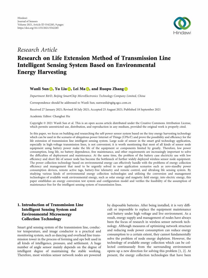
1.1. Solar Energy. Solar energy extraction mainly convertslight energy into electric energy through solar panels to sup-ply power for sensors. Since the energy intensity of lightenergy varies greatly with time, solar panels are often com-bined with batteries to form solar power supply systems inpractical applications [3]. The principle is shown inFigure 1. The solar power supply system is relatively mature,with high energy conversion efficiency.
The conversion efficiency of mass-produced photovol-taic cells can reach up to 18%, and the energy density isabout 3mW/cm2. However, the application effect is limitedby natural conditions and battery life [4].
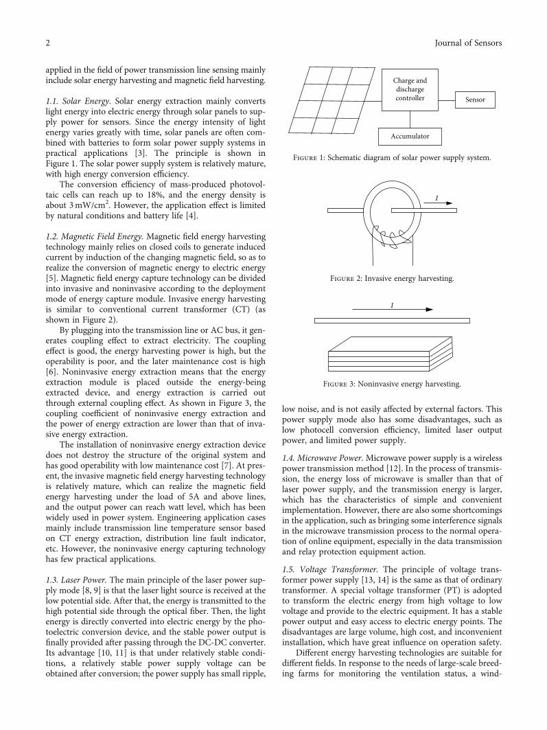
1.2. Magnetic Field Energy. Magnetic field energy harvestingtechnology mainly relies on closed coils to generate inducedcurrent by induction of the changing magnetic field, so as torealize the conversion of magnetic energy to electric energy[5]. Magnetic field energy capture technology can be dividedinto invasive and noninvasive according to the deploymentmode of energy capture module. Invasive energy harvestingis similar to conventional current transformer (CT) (asshown in Figure 2).
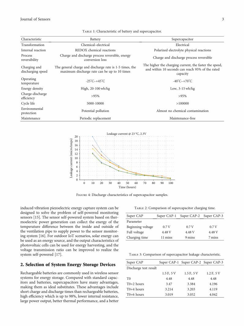
By plugging into the transmission line or AC bus, it gen-erates coupling effect to extract electricity. The couplingeffect is good, the energy harvesting power is high, but theoperability is poor, and the later maintenance cost is high[6]. Noninvasive energy extraction means that the energyextraction module is placed outside the energy-beingextracted device, and energy extraction is carried outthrough external coupling effect. As shown in Figure 3, thecoupling coefficient of noninvasive energy extraction andthe power of energy extraction are lower than that of inva-sive energy extraction.
The installation of noninvasive energy extraction devicedoes not destroy the structure of the original system andhas good operability with low maintenance cost [7]. At pres-ent, the invasive magnetic field energy harvesting technologyis relatively mature, which can realize the magnetic fieldenergy harvesting under the load of 5A and above lines,and the output power can reach watt level, which has beenwidely used in power system. Engineering application casesmainly include transmission line temperature sensor basedon CT energy extraction, distribution line fault indicator,etc. However, the noninvasive energy capturing technologyhas few practical applications.
1.3. Laser Power. The main principle of the laser power sup-ply mode [8, 9] is that the laser light source is received at thelow potential side. After that, the energy is transmitted to thehigh potential side through the optical fiber. Then, the lightenergy is directly converted into electric energy by the pho-toelectric conversion device, and the stable power output isfinally provided after passing through the DC-DC converter.Its advantage [10, 11] is that under relatively stable condi-tions, a relatively stable power supply voltage can beobtained after conversion; the power supply has small ripple,
low noise, and is not easily affected by external factors. Thispower supply mode also has some disadvantages, such aslow photocell conversion efficiency, limited laser outputpower, and limited power supply.
1.4. Microwave Power. Microwave power supply is a wirelesspower transmission method [12]. In the process of transmis-sion, the energy loss of microwave is smaller than that oflaser power supply, and the transmission energy is larger,which has the characteristics of simple and convenientimplementation. However, there are also some shortcomingsin the application, such as bringing some interference signalsin the microwave transmission process to the normal opera-tion of online equipment, especially in the data transmissionand relay protection equipment action.
1.5. Voltage Transformer. The principle of voltage trans-former power supply [13, 14] is the same as that of ordinarytransformer. A special voltage transformer (PT) is adoptedto transform the electric energy from high voltage to lowvoltage and provide to the electric equipment. It has a stablepower output and easy access to electric energy points. Thedisadvantages are large volume, high cost, and inconvenientinstallation, which have great influence on operation safety.
Different energy harvesting technologies are suitable fordifferent fields. In response to the needs of large-scale breed-ing farms for monitoring the ventilation status, a wind-
Charge anddischargecontroller
Accumulator
Sensor
Figure 1: Schematic diagram of solar power supply system.
I
Figure 2: Invasive energy harvesting.
I
Figure 3: Noninvasive energy harvesting.
2 Journal of Sensors
induced vibration piezoelectric energy capture system can bedesigned to solve the problem of self-powered monitoringsensors [15]. The sensor self-powered system based on ther-moelectric power generation can collect the energy of thetemperature difference between the inside and outside ofthe ventilation pipe to supply power to the sensor monitor-ing system [16]. For outdoor IoT scenarios, solar energy canbe used as an energy source, and the output characteristics ofphotovoltaic cells can be used for energy harvesting, and thevoltage transmission ratio can be improved to realize thesystem self-powered [17].
2. Selection of System Energy Storage Devices
Rechargeable batteries are commonly used in wireless sensorsystems for energy storage. Compared with standard capac-itors and batteries, supercapacitors have many advantages,making them as ideal substitutes. These advantages includeshort charge and discharge times than rechargeable batteries,high efficiency which is up to 98%, lower internal resistance,large power output, better thermal performance, and a better
Table 1: Characteristic of battery and supercapacitor.
Characteristic Battery Supercapacitor
Transformation Chemical–electrical Electrical
Internal reaction REDOX chemical reactions Polarized electrolyte physical reactions
Processreversibility
Charge and discharge process reversible, energyconversion loss
Charge and discharge process reversible
Charging anddischarging speed
The general charge and discharge rate is 1-5 times, themaximum discharge rate can be up to 10 times
The higher the charging current, the faster the speed,and within 10 seconds can reach 95% of the rated
capacity
Operatingtemperature
-25°C–+45°C -40°C–+70°C
Energy density High, 20-100wh/kg Low, 3-15wh/kg
Charge-dischargeefficiency
>95% >95%
Cycle life 5000-10000 >100000Environmentalprotection
Potential pollution Almost no chemical contamination
Maintenance Periodic replacement Maintenance-free
02468
101214161820
0 10 20 30 40 50 60 70 80 90 100
Leak
age c
urre
nt (m
icro
Am
ps)
Time (hours)
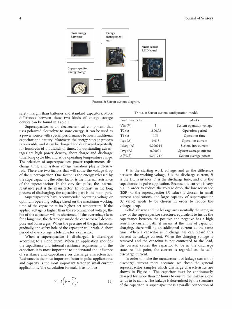
Leakage current @ 23 °C, 2.3V
Figure 4: Discharge characteristics of supercapacitor samples.
Table 2: Comparison of supercapacitor charging time.
Super CAP Super CAP-1 Super CAP-2 Super CAP-3
Parameter
Beginning voltage 0.7 V 0.7V 0.7 V
Full voltage 4.48V 4.48V 4.48V
Charging time 11mins 9mins 7mins
Table 3: Comparison of supercapacitor leakage characteristic.
Super CAP Super CAP-1 Super CAP-2 Super CAP-3
Discharge test result
1.5 F, 5 V 1.5 F, 5V 1.2 F, 5V
T0 4.48 4.48 4.48
T0+2 hours 3.47 3.384 4.196
T0+4 hours 3.214 3.203 4.119
T0+6 hours 3.019 3.052 4.042
3Journal of Sensors
safety margin than batteries and standard capacitors. Moredifferences between these two kinds of energy storagedevices can be found in Table 1.
Supercapacitor is an electrochemical component thatuses polarized electrolyte to store energy. It can be used asa power source with special performance between traditionalcapacitor and battery. Moreover, the energy storage processis reversible, and it can be charged and discharged repeatedlyfor hundreds of thousands of times. Its outstanding advan-tages are high power density, short charge and dischargetime, long cycle life, and wide operating temperature range.The selection of supercapacitors, power requirements, dis-charge time, and system voltage variation play a decisiverole. There are two factors that will cause the voltage dropof the supercapacitor. One factor is the energy released bythe supercapacitor; the other factor is the internal resistanceof the supercapacitor. In the very fast pulse, the internalresistance part is the main factor. In contrast, in the longprocess of discharging, the capacitive part is the main part.
Supercapacitors have recommended operating voltage oroptimum operating voltage based on the maximum workingtime of the capacitor at its highest set temperature. If theapplied voltage is higher than the recommended voltage, thelife of the capacitor will be shortened. If the overvoltage lastsfor a long time, the electrolyte inside the capacitor will decom-pose and form a gas. When the pressure of the gas increasesgradually, the safety hole of the capacitor will break. A shortperiod of overvoltage is tolerable for a capacitor.
When a supercapacitor is discharged, it dischargesaccording to a slope curve. When an application specifiesthe capacitance and internal resistance requirements of thecapacitor, it is most important to understand the influenceof resistance and capacitance on discharge characteristics.Resistance is the most important factor in pulse applications,and capacity is the most important factor in small currentapplications. The calculation formula is as follows:
V = I R + TC
� �: ð1Þ
V is the starting work voltage, and as the differencebetween the working voltage, I is the discharge current, Ris the DC resistance, T is the discharge time, and C is thecapacitance in pulse application. Because the current is verybig, in order to reduce the voltage drop, the low resistance(ESR) of the supercapacitor (R value) is chosen; in smallcurrent applications, the large capacity of supercapacitor(C value) needs to be chosen in order to reduce thevoltage drop.
Self-discharge and the leakage are essentially the same, inview of the supercapacitor structure, equivalent to inside thecapacitance between the positive and negative has a highresistance current path; it means at the time of capacitorcharging, there will be an additional current at the sametime. When a capacitor is in charge, we can regard thiscurrent as leakage current. When the charging voltage isremoved and the capacitor is not connected to the load,the current causes the capacitor to be in the dischargestate. At this point, the current is regarded as the self-discharge current.
In order to make the measurement of leakage current ordischarge current more accurate, we chose the generalsupercapacitor samples which discharge characteristics areshown in Figure 4. The capacitor must be continuouslycharged for more than 72 hours to ensure the leakage slopetends to be stable. The leakage is determined by the structureof the capacitor. A supercapacitor is a parallel connection of
Sloar energyharvester
Energymanagementunit
Super-capacitorenergy storage
Smart sensorRFID board
Figure 5: Sensor system diagram.
Table 4: Sensor system configuration model.
Load parameter Marks
Vin (V) 3 System operation voltage
T0 (s) 1800.73 Operation period
T1 (s) 0.73 Operation time
Isys (A) 0.015 Operation current
Isleep (A) 0.000014 System-free current
Iavg (A) 0.00001 System average current
c (W/S) 0.001217 System average power
4 Journal of Sensors
several supercapacitors with different internal resistances.When the supercapacitor is charged, the supercapacitor withlow internal resistance charges fast, and the voltage canquickly rise to the value of the charging voltage. When thecharging voltage of the supercapacitor is removed, if the highinternal resistance supercapacitor is not fully charged, thelow internal resistance supercapacitor starts to discharge tothe parallel high internal resistance supercapacitor, so thatthe voltage across the capacitor will drop relatively fast.The capacitor is usually considered as a relatively largeself-discharge. It must be noted that the larger the capaci-tance of the capacitor, the longer it takes for the capacitorto be fully charged.
In this paper, three types of supercapacitors are selectedto test the actual charge-discharge effect. The system is setwith an overvoltage protection of 4.5V and a dischargethreshold of 2.8V. The test results are as follows:
According to the test data shown in Tables 2 and 3,supercap-3 has excellent performance in terms of the overall
charge-discharge effect and self-leakage; supercap-3 isselected as the energy storage element of the system.
3. Verification of Self-Powered Sensor SystemBased on Microsolar EnergyExtraction Sensor
With the development of ubiquitous power Internet ofThings, all kinds of wireless smart sensors are graduallywidely used. In order to solve the problem of energy acqui-sition, support the long life cycle, and reduce the cost ofmanual maintenance of power system, this system focuseson the investigation of the energy demand of passive sensorscommonly used in power system and selected the represen-tative smart sensor RFID system as the research object toverify the feasibility.
The system converts solar energy into electric energythrough a 2:5 cm ∗ 2:5 cm solar panel suitable for small
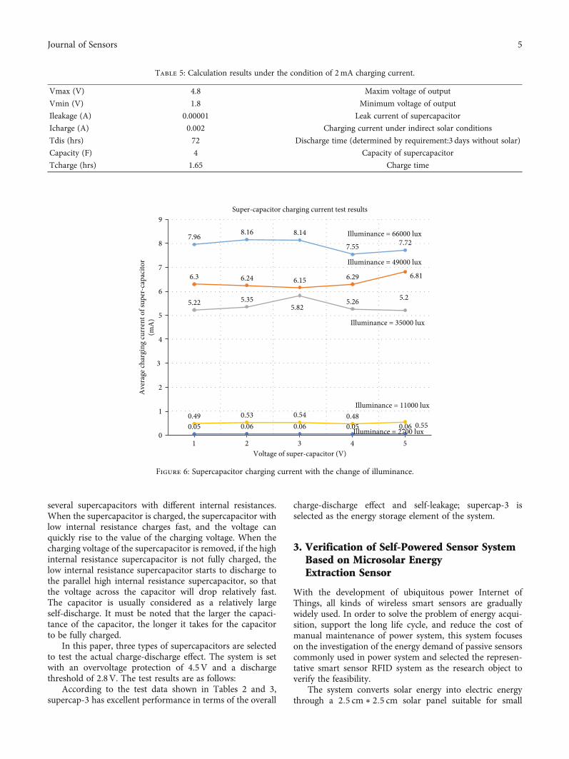
Table 5: Calculation results under the condition of 2mA charging current.
Vmax (V) 4.8 Maxim voltage of output
Vmin (V) 1.8 Minimum voltage of output
Ileakage (A) 0.00001 Leak current of supercapacitor
Icharge (A) 0.002 Charging current under indirect solar conditions
Tdis (hrs) 72 Discharge time (determined by requirement:3 days without solar)
Capacity (F) 4 Capacity of supercapacitor
Tcharge (hrs) 1.65 Charge time
7.96 8.16 8.14
7.55 7.72
6.3 6.24 6.15 6.29 6.81
5.22 5.355.82
5.26 5.2
0.49 0.53 0.54 0.480.550.05 0.06 0.06 0.05 0.06
0
1
2
3
4
5
6
7
8
9
1 2 3 4 5
Ave
rage
char
ging
curr
ent o
f sup
er-c
apac
itor
(mA
)
Voltage of super-capacitor (V)
Super-capacitor charging current test results
Illuminance = 66000 lux
Illuminance = 49000 lux
Illuminance = 35000 lux
Illuminance = 11000 lux
Illuminance = 2700 lux
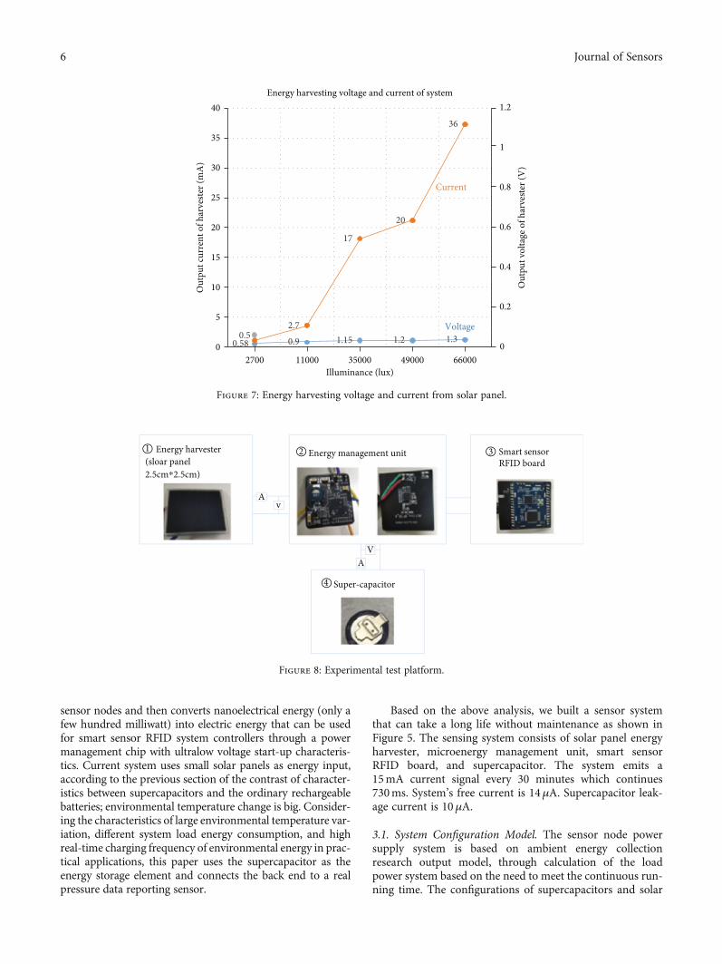
Figure 6: Supercapacitor charging current with the change of illuminance.
5Journal of Sensors
sensor nodes and then converts nanoelectrical energy (only afew hundred milliwatt) into electric energy that can be usedfor smart sensor RFID system controllers through a powermanagement chip with ultralow voltage start-up characteris-tics. Current system uses small solar panels as energy input,according to the previous section of the contrast of character-istics between supercapacitors and the ordinary rechargeablebatteries; environmental temperature change is big. Consider-ing the characteristics of large environmental temperature var-iation, different system load energy consumption, and highreal-time charging frequency of environmental energy in prac-tical applications, this paper uses the supercapacitor as theenergy storage element and connects the back end to a realpressure data reporting sensor.
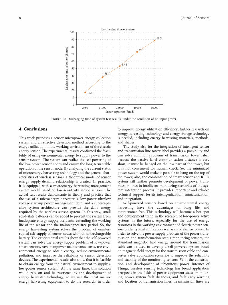
Based on the above analysis, we built a sensor systemthat can take a long life without maintenance as shown inFigure 5. The sensing system consists of solar panel energyharvester, microenergy management unit, smart sensorRFID board, and supercapacitor. The system emits a15mA current signal every 30 minutes which continues730ms. System’s free current is 14μA. Supercapacitor leak-age current is 10μA.
3.1. System Configuration Model. The sensor node powersupply system is based on ambient energy collectionresearch output model, through calculation of the loadpower system based on the need to meet the continuous run-ning time. The configurations of supercapacitors and solar
0.58 0.9 1.15 1.2 1.30.52.7
17
20
36
0
0.2
0.4
0.6
0.8
1
1.2
0
5
10
15
20
25
30
35
40
2700 11000 35000 49000 66000
Out
put v
olta
ge o
f har
veste
r (V
)
Out
put c
urre
nt o
f har
veste
r (m
A)
Illuminance (lux)
Energy harvesting voltage and current of system
Current
Voltage
Figure 7: Energy harvesting voltage and current from solar panel.
Energy harvester(sloar panel2.5cm⁎2.5cm)
Energy management unit
A
AV
v
Smart sensorRFID board
Super-capacitor4
321
Figure 8: Experimental test platform.
6 Journal of Sensors
panels are required to guide the system hardware architec-ture of the subsequent application design. At the same time,it can be used to evaluate the efficiency of the docking ofother energy extraction devices.
Firstly, the average power of the system is calculatedthrough the load power consumption, and the results areshown in Table 4.
P average powerð Þ = Vin × Isys × T1ð Þ + Vin × Isleep × T3ð Þ½ �T0
,
ð2Þ
Iavg average currentð Þ = Isys × T1ð Þ + Isleep × T3ð Þ½ �T0
: ð3Þ
According to the system configuration in the previoussection, the following data parameters can be obtained.According to the above formula, the average power con-sumption of the system under the configuration conditionof the system is 1.217mW, which can be used to calculatethe supercapacitor configuration of the subsequent systemunder the condition of no light for 3 days.
The requirements of working voltage threshold, loadcurrent, the self-leakage, and working time of the supercapa-citor are important, and the factors also were analyzed in theprevious section; the capacitance required by the system canbe calculated according to the average leakage of current,and the formula is shown as follows:
Capacity Fð Þ = V max +V minð Þ × I ×t
V max2 −V min2
=V max +V minð Þ × Ileakage × 60 × 60
V max 2 −V min 2ð Þ ,
ð4Þ
Tcharge Charge timeð Þ = C × Vmax −Vminð Þ/Icharge½ �3600
:
ð5Þ
Table 5 shows the calculation results according to thecharging efficiency after the output current of solar panelsunder solar indirect conditions converted by the powermanagement system, and the charging current is 2mA.
Finally, the result obtained through the data model sim-ulation is that when the ultralow power management systemis configured with the upper limit of the charging voltage ofthe supercapacitor is 4.8V, and the discharge is as low as1.8V; the size of the supercapacitor required for the systemto maintain no light for 3 days is 4 Farad.
3.2. Experimental Test Platform and Results. In order to eval-uate the system feasibility, we developed an experimentaltest platform, as shown in Figure 5, which is comprised ofenergy harvester, energy management element, supercapaci-tor, and smart sensor RFID board as load. One supercapaci-tor was chosen as an electric storage element to be evaluatedconsidering the situation for nonlight. Two ammeters (A)
and voltmeters (V) are used for measurements of currentand voltage, respectively.
It is very meaningful to test system charging currentunder the real different lighting conditions. Figure 6 showsthe test results of supercapacitor charging current underthe change of illuminance, the stronger the light, the greaterthe charging current. If the illuminance is 66000 lux, thecharging current of system can reach 7.55mA with the4-Farad supercapacitor.
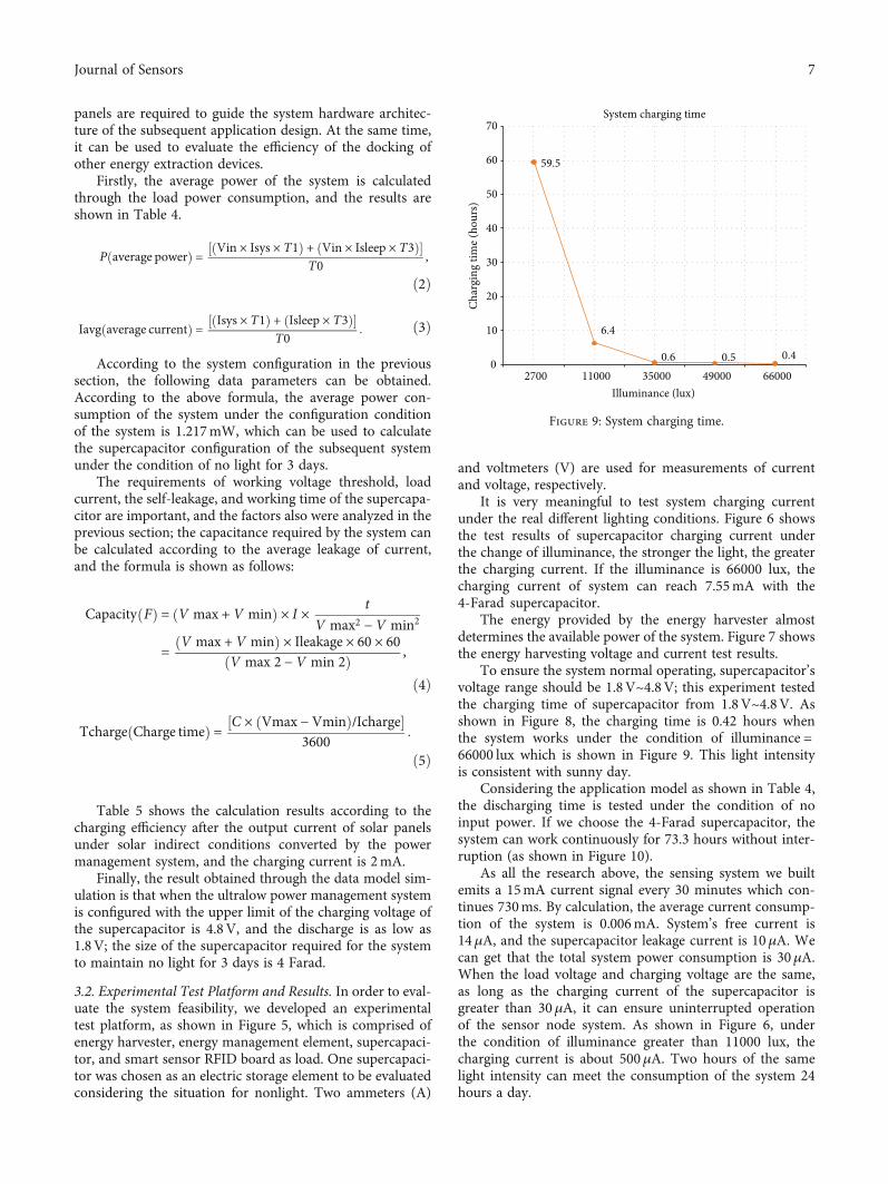
The energy provided by the energy harvester almostdetermines the available power of the system. Figure 7 showsthe energy harvesting voltage and current test results.
To ensure the system normal operating, supercapacitor’svoltage range should be 1.8V~4.8V; this experiment testedthe charging time of supercapacitor from 1.8V~4.8V. Asshown in Figure 8, the charging time is 0.42 hours whenthe system works under the condition of illuminance =66000 lux which is shown in Figure 9. This light intensityis consistent with sunny day.
Considering the application model as shown in Table 4,the discharging time is tested under the condition of noinput power. If we choose the 4-Farad supercapacitor, thesystem can work continuously for 73.3 hours without inter-ruption (as shown in Figure 10).
As all the research above, the sensing system we builtemits a 15mA current signal every 30 minutes which con-tinues 730ms. By calculation, the average current consump-tion of the system is 0.006mA. System’s free current is14μA, and the supercapacitor leakage current is 10μA. Wecan get that the total system power consumption is 30μA.When the load voltage and charging voltage are the same,as long as the charging current of the supercapacitor isgreater than 30μA, it can ensure uninterrupted operationof the sensor node system. As shown in Figure 6, underthe condition of illuminance greater than 11000 lux, thecharging current is about 500μA. Two hours of the samelight intensity can meet the consumption of the system 24hours a day.
59.5
6.4
0.6 0.5 0.40
10
20
30
40
50
60
70
2700 11000 35000 49000 66000
Char
ging
tim
e (ho
urs)
Illuminance (lux)
System charging time
Figure 9: System charging time.
7Journal of Sensors
4. Conclusions
This work proposes a sensor micropower energy collectionsystem and an effective detection method according to theenergy utilization in the working environment of the electricenergy sensor. The experimental results confirmed the feasi-bility of using environmental energy to supply power to thesensor system. The system can realize the self-powering ofthe low-power sensor nodes and ensure the long-term stableoperation of the sensor node. By analyzing the current statusof microenergy harvesting technology and the general char-acteristics of wireless sensors, a theoretical model of sensorenergy supply-demand relationship is created. In practice,it is equipped with a microenergy harvesting managementsystem model based on low-sensitivity sensor sensors. Theactual test results demonstrate in theory and practice thatthe use of a microenergy harvester, a low-power ultralowvoltage start-up power management chip, and a supercapa-citor system architecture can provide the daily energyrequired by the wireless sensor system. In this way, smallsolid-state batteries can be added to prevent the system frominadequate energy supply accidents, extending the workinglife of the sensor and the maintenance-free period. So, theenergy harvesting system solves the problem of uninter-rupted self-supply of sensor nodes without nonrechargeablebattery. The experimental results show that the self-poweredsystem can solve the energy supply problem of low-powersmart sensors, save manpower maintenance costs, use envi-ronmental energy to obtain energy, reduce environmentalpollution, and improve the reliability of sensor detectiondevices. The experimental results also show that it is feasibleto obtain energy from the natural environment to supply alow-power sensor system. At the same time, this solutionwould rely on and be restricted by the development ofenergy harvester technology, so we use the most matureenergy harvesting equipment to do the research; in order
to improve energy utilization efficiency, further research onenergy harvesting technology and energy storage technologyis needed, including energy harvesting materials, methods,and shapes.
The study also for the integration of intelligent sensorand transmission line tower label provides a possibility andcan solve common problems of transmission tower label,because the passive label communication distance is veryshort; it must be hanged on the low part of the tower, butit is not convenient for human check. So, the minimizedpower system would make it possible to hang on the top ofthe tower; also, the combination of smart sensor and RFIDsystem will further promote development of power trans-mission lines in intelligent monitoring scenarios of the sys-tem integration process. It provides important and reliabletechnical support for its intelligentization, miniaturization,and integration.
Self-powered sensors based on environmental energyharvesting have the advantages of long life andmaintenance-free. This technology will become a hot spotand development trend in the research of low-power activesystems in the future, especially for the use of energyresources in the working environment of electric power sen-sors under typical application scenarios of electric power. Inorder to solve the power supply problem of the power trans-mission and transformation status monitoring sensors, theabundant magnetic field energy around the transmissioncable can be used to develop a self-powered system basedon magnetic field energy for the transmission cable and con-verter valve application scenarios to improve the reliabilityand stability of the monitoring sensors. With the construc-tion and development of ubiquitous power Internet ofThings, wireless sensing technology has broad applicationprospects in the fields of power equipment status monitor-ing, power system fault diagnosis, and fault early warningand location of transmission lines. Transmission lines are
17.3
38.1
53.4
73.3
88.9
0
10
20
30
40
50
60
70
80
90
100
2700 11000 35000 49000 66000
Disc
harg
ing
time o
f sys
tem
(hou
rs)
Super-capacitor (farad)
Discharging time of system
Figure 10: Discharging time of system test results, under the condition of no input power.
8 Journal of Sensors
an important part of the power grid. Regular inspections oftransmission lines are the main means to ensure the normaloperation of the power grid. Regular inspections wastemanpower, financial resources, and material resources, sostate inspections are used. As temperature sensor, humiditysensor, or strain clamp sensor that detect important statesof transmission lines, its power supply cannot meet thelong-term and reliable operation of the sensor. The multipa-rameter energy harvesting system can solve the powersupply problem of a variety of wireless sensor devices.
Data Availability
The data used to support the findings of this study areincluded within the article.
Conflicts of Interest
There is no conflict of interest regarding the publication ofthis paper.
Acknowledgments
This study was funded by the project “Research on commu-nication protocol of power wireless sensor network forpower transmission and transformation state monitoringand development of prototype” which belongs to theDepartment R&D, Beijing SmartChipMicroElectronicsTechnology Company Limited.
References
[1] Z. H. O. U. Feng, Z. H. O. U. Hui, and D. I. A. O. Yinglong,“Development of intelligent perception key technology in theubiquitous Internet of Things in electricity,” Proceedings ofthe CSEE, vol. 40, no. 1, pp. 70–82, 2020.
[2] J. I. A. N. G. Xiuchen, L. I. U. Yadong, and F. U. Xiaofei, “Con-struction ideas and development trends of transmission anddistribution equipment of the ubiquitous power Internet ofThings,” High Voltage Engineering, vol. 45, no. 5, pp. 1345–1351, 2019.
[3] Z. H. U. Yongcan, H. U. A. N. G. Xinbo, and Z. H. A. N. G.Guanjun, “Application research of the power supply for trans-mission line on-line monitoring devices,” High Voltage Appa-ratus, vol. 54, no. 7, pp. 231–236, 2018.
[4] Z. H. A. N. G. Min, Q. I. N. Yu, and W. A. N. G. Hongbin,“Design of power supply source of transmission line on-linemonitoring device,” Guangdong Electric Power, vol. 31,no. 10, pp. 94–100, 2018.
[5] G. U. O. Shen, W. A. N. G. Peng, and Z. H. A. N. G. Jichuan,“An overview of electromagnetic energy collection and storagetechnologies for a high voltage transmission system,” EnergyStorage Science and Technology, vol. 8, no. 1, pp. 32–46, 2019.
[6] P. E. N. G. Xiying, C. U. I. Dandan, and Z. H. A. O. Qiangsong,“Energy collection based power supply for monitoring equip-ment on transmission line,” Mechanical Engineering & Auto-mation, vol. 2, pp. 192–194, 2017.
[7] L. I. Dong, “Study on magnetoelectric energy conversion tech-nique used for space magnetic energy harvesting in substa-tion,” Electrotechnics Electric, vol. 6, pp. 10–15, 2017.
[8] C. Wang and B. S. Liyi, “Analysis and research on laser powersupply condition of electronic current transformer under lowtemperature environment,” High Voltage Apparatus, vol. 56,no. 5, pp. 0135–0142, 2020.
[9] Zhou, “A low current ripple power supply of laser diode forwireless power transfer,” Chinese Science and TechnologyPapers, vol. 12, no. 11, pp. 1252–1256, 2017.
[10] Y. Shen, J.-m. Ge, R.-t. Liu, W. Fan, and Y.-X. Yang, “Optimi-zation of optical current sensor based on rare-earth magneto-optical glass,” Microwave and Optical Technology Letters,vol. 61, no. 2, pp. 490–497, 2019.
[11] P. Sarajcev and D. Jakus, “Optimal scheduling of power trans-formers preventive maintenance with Bayesian statisticallearning and influence diagrams,” Journal of Cleaner Produc-tion, vol. 258, p. 120850, 2020.
[12] A. V. Ubaychin, T. A. Uulu, and G. Zhuk,Microwave Radiom-eter for Sensor Systems with Self-Contained Power SuppliesSJEM026022880037, Emerald, England, 2020.
[13] P. Bocui, “Research on high voltage side power supply schemeof active electronic voltage transformer,”Mechanical and elec-trical engineering, vol. 29, no. 11, pp. 1323–1328, 2012.
[14] H. Rui, Research on Energy Management of Self-PoweredWire-less Sensor System Based on Environmental Energy Harvesting,University of Electronic Science and Technology of China,2019.
[15] W. Zhidong, F. Junlong, S. Peidong, F. Yuchen, W. Guangya,and P. Di, “Design method of self-powered sensor systembased on piezoelectricity,” Journal of Beijing Institute of Tech-nology, vol. 40, no. 12, 2020.
[16] W. Zhidong, Z. Hongbin, F. Yuchen, C. Youjie, and B. Li,“Design of sensor self-powered system based on thermoelec-tric power generation,” Laboratory research and exploration,vol. 39, no. 11, 2020.
[17] L. Shuiping and C. Jiahao, “Design of self-powered wirelesssensor network nodes based on wind energy harvesting,” Dig-ital Manufacturing Science, vol. 18, no. 04, 2020.
9Journal of Sensors