research on the parameters of hifu based on near-field
TRANSCRIPT
Research on the Parameters of HIFU Based on Near-field Cross-spectrum Method
Zhuohan Tang*, Huifeng Zheng, Jiayu Gao, Linjing Wu and Yanchao Wang China Jiliang University, Hangzhou, China
*Corresponding author
Abstract—This paper aims at the measurement problem of High Intensity Focused Ultrasound (HIFU). In order to measure the sound parameters of HIFU, we study the near-field cross-spectrum method. That is to say, the complex sound pressure of two adjacent planes can be measured in the near field, besides, the sound power and the sound intensity can be obtained through the cross-spectrum relationship between two groups of sound pressure. For verifying the theory, we used a self-built underwater acoustic field measurement system to compare the far-field method with the near-field cross-spectrum method by measuring the sound power of the plane piston transducer, and the result shows that the near-field cross-spectrum method is reliable in the effective range of acoustic error.
Keywords—HIFU technology; near-field cross-spectrum method; sound intensity; sound power
I. INTRODUCTION
High intensity focused ultrasound (HIFU) is a kind of surgical technique that can selectively damage the lesion tissue in the target area with high intensity ultrasound. The source of HIFU is ultrasound, and the main physical mechanism is the thermal effect, which is, transient high temperature. If the dose of ultrasound treatment can not be properly controlled, the normal cells might be compromised. Due to the difficulty of detecting the HIFU equipment, it is a challenge to ensure that the ultrasonic dose in the non-detection period always in accordance with the set dose. Because of the limitations in many uncertain factors on HIFU technology and the complexity of the local anatomical structure, there still lacks real-time and accurate monitoring methods[1].
Nowadays, in practice, radiation force balance (RFB), hydrophone, optical fiber detection and optical detection are the main detection methods of HIFU sound field, including acoustic power, sound pressure and sound intensity. Among them, hydrophone method is the most widely used one, and it has the advantages like wide frequency response, large dynamic range and good linearity. However, it’s hard for the hydrophone probes to bear high intensity sound pressure, and there are widespread shortcomings such as large volume of the device and easily damaged. To solve these problems, near-field cross-spectrum method is a desire measurement to measured the sound pressure, sound intensity and sound power of HIFU, so as to realize the on-site detection and calibration of HIFU sound parameters, providing an effective way for the accurate measurement of HIFU. It also
overcomes the drawback that traditional hydrophone probe is difficult to bear the high intensity sound pressure.
II. THEORY
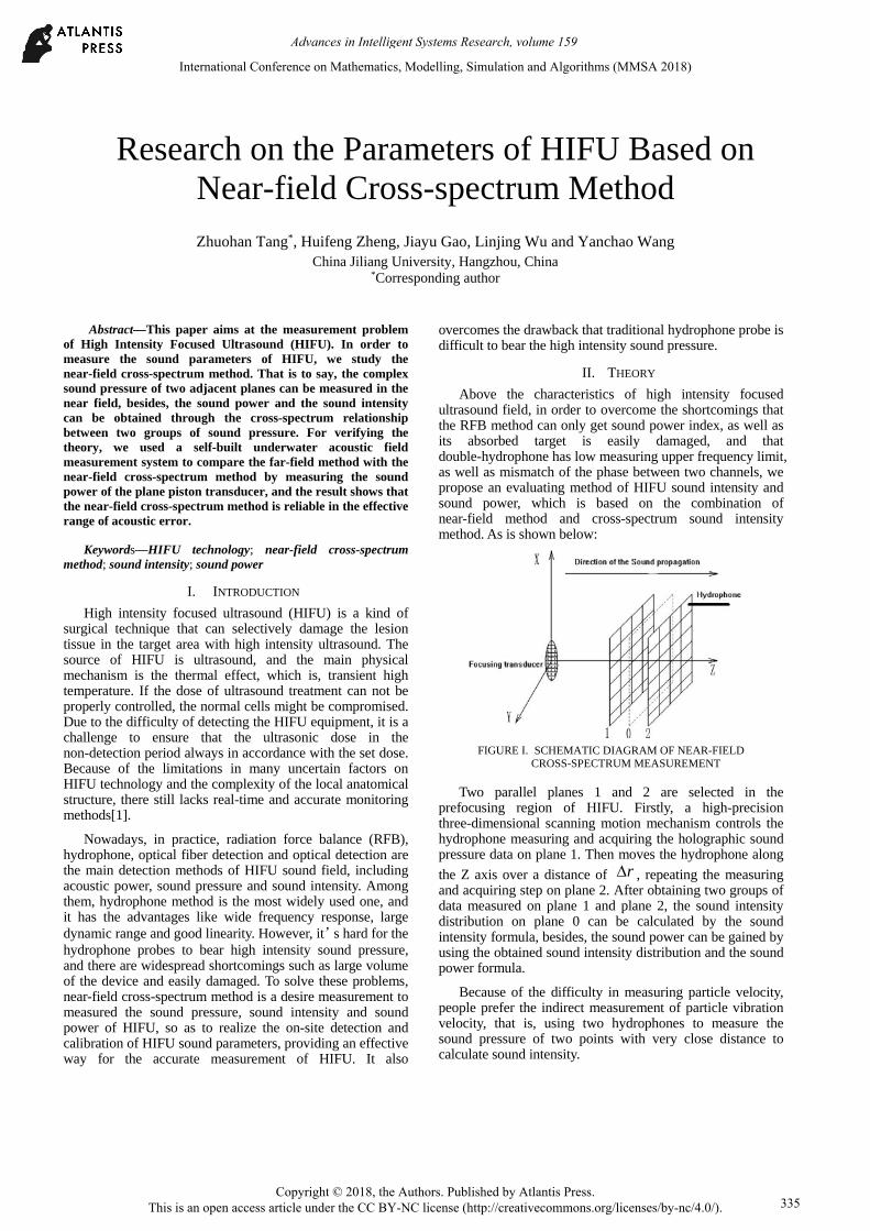
Above the characteristics of high intensity focused ultrasound field, in order to overcome the shortcomings that the RFB method can only get sound power index, as well as its absorbed target is easily damaged, and that double-hydrophone has low measuring upper frequency limit, as well as mismatch of the phase between two channels, we propose an evaluating method of HIFU sound intensity and sound power, which is based on the combination of near-field method and cross-spectrum sound intensity method. As is shown below:
FIGURE I. SCHEMATIC DIAGRAM OF NEAR-FIELD
CROSS-SPECTRUM MEASUREMENT
Two parallel planes 1 and 2 are selected in the prefocusing region of HIFU. Firstly, a high-precision three-dimensional scanning motion mechanism controls the hydrophone measuring and acquiring the holographic sound pressure data on plane 1. Then moves the hydrophone along
the Z axis over a distance of r , repeating the measuring and acquiring step on plane 2. After obtaining two groups of data measured on plane 1 and plane 2, the sound intensity distribution on plane 0 can be calculated by the sound intensity formula, besides, the sound power can be gained by using the obtained sound intensity distribution and the sound power formula.
Because of the difficulty in measuring particle velocity, people prefer the indirect measurement of particle vibration velocity, that is, using two hydrophones to measure the sound pressure of two points with very close distance to calculate sound intensity.
International Conference on Mathematics, Modelling, Simulation and Algorithms (MMSA 2018)
Copyright © 2018, the Authors. Published by Atlantis Press. This is an open access article under the CC BY-NC license (http://creativecommons.org/licenses/by-nc/4.0/).
Advances in Intelligent Systems Research, volume 159
335

For the smooth random process, the cross-correlative function[2] between the sound pressure )(tP and particle
velocity )(tu at position 0 can be expressed as:
0
1( ) lim ( ) ( )d
T
pu TR p t t tT
u (1)
When 0 , sound intensity can be calculated according to the Wiener-Khinchin principle[3] :
(0) ( )d
pu puI R S (2)
Single side spectrum can be obtained according to the relevant theorems:
2( ) lim [ ( ) ( )]pu TG P U
T
(3)
Organize the above equations:
Im[ ]( ) Re[ ( )] AB
pu
GI G
r
(4)
By getting the imaginary part of the cross spectrum about two sound pressure signals, the sound intensity frequency distribution in the center of two sound pressure sensors can be easily obtained.
The sound source's radiated power[4] can be calculated by integrating the area of sound intensity, that is:
d S
P I s (5)
Where P is the sound source's radiated power, S is
the enveloping surface and I is the sound intensity.
III. EXPERIMENTAL STUDY
According to the proposed sound intensity and sound power measurement, we choose the hydrophone method to measure the sound field. The measurement of sound parameters is completed by using the three-dimensional motion of the hydrophone in space and data acquisition. Analyzing from the following two aspects.
A. Experimental System
In order to study underwater acoustic field, the hydrophone is connected to the oscilloscope through the cable. The oscilloscope will display the voltage waveform containing the acoustic wave information, and the sound pressure information can be easily obtained by processing the voltage waveform. In this paper, a set of underwater acoustic field measurement system is built by using hydrophone as the measuring tool and oscilloscope as the
data acquisition tool. The measuring system equipped with power amplifier, signal source and high-precision three-dimensional motion mechanism. as is shown in the following figures.
(a)
(b)
FIGURE II. MEASURING SYSTEM (A)MECHANICAL CONNECTION PART (B)SIGNAL CONNECTION PART
The schematic diagram of measurement system is shown in Figure 3, which includes signal source, power amplifier, high-precision three-dimensional motion mechanism, hydrophone, preamplifier, digital oscilloscope, program-controlled computer and so on. The signal transmitted by the signal source is synchronized to the digital oscilloscope, meanwhile, it will be amplified by the power amplifier and stimulate the transducer to transmit sound wave, then the radiation sound field can be formed in the pool. The hydrophone is installed on the high-precision three-dimensional scanning motion mechanism. The hydrophone will receive the signal and display it by the digital oscilloscope. The synchronous signal is connected to the digital oscilloscope by trigger input, which is used to capture sound pressure waveform and calculate time delay. The program-controlled computer controls the hydrophone scanning the acoustic field, and reads the signals collected by the digital oscilloscope through the serial ports, getting the sound pressure distribution on the measuring plane.
Advances in Intelligent Systems Research, volume 159
336

FIGURE III. A SCHEMATIC DIAGRAM OF SOUND PRESSURE
MEASUREMENT SYSTEM FOR UNDERWATER ACOUSTIC TRANSDUCER
B. Experimental Results and Analysis
The near-field cross-spectrum measuring method proposed in this paper is verified by the far-field measuring method of plane piston transducer.
1) Far-field Measurement Experimental selection of the plane piston transducer
diameter is 90mm, and the resonant frequency is 40kHz. Selecting a standard ball hydrophone, whose diameter is 20mm, and the frequency response in the low frequency range does not exceed 10dB. Figure of Ball hydrophone and piston transducer are shown as figure 3:
(a)
(b)
FIGURE IV. PLANE PISTON TRANSDUCER AND BALL HYDROPHONE (A)PISTON TRANSDUCER (B)BALL
HYDROPHONE
The sensitivity calibration data of the ball hydrophone is shown in Table 1:
TABLE I. THE BALL HYDROPHONE SENSITIVITY CALIBRATION DATA
f(kHz) M0(dB) f(kHz) M0(dB)
3.15 -196.9 15 -201.6 4 -196.7 20 -203
5 -196.4 25 -203.3
6.3 -197 30 -202.6
8 -198.8 40 -205.5
10 -199.1 50 -204.6
12 -200
Since the directivity of the planar piston transducer does not appear until 10 times the far-field distance, the plane piston transducer and the ball hydrophone are placed at the same depth under water and 2.7m apart, with the working end surface in parallel. The signal transmission frequency is 40kHz, the VPP is 2V, the repetition frequency is 25Hz and the number of pulses is 10 sine pulse signals. The signal will be amplified by the LPA-100 intermediate frequency power amplifier, then stimulates the plane piston transducer to form the radiation sound field in water.
The sound power obtained at far-field is 2.81186W.
2) Near-field Cross-spectrum Measurement The system designed in this paper is used to measure the
near-field cross-spectrum at the Fresnel zone of the plane piston transducer. Due to the intense sound pressure fluctuations in the Fresnel zone and the large size of the ball hydrophone, the low spatial resolution is not suitable for near-field cross-spectrum measurements. Therefore, ONDA's bulkhead hydrophone is chosen for the measurement, It’s working face is only 0.4mm. The chosen hydrophone is shown as figure 5.
FIGURE V. ONDA’S BULKHEAD HYDROPHONE
Sensitive data of the ONDA hydrophone is shown in Figure 6. The measuring uncertainty of frequency in1-15MHz is less than 1dB, and in 15-20MHz is less than 1.5dB.
Advances in Intelligent Systems Research, volume 159
337

FIGURE VI. SENSITIVE CURVE OF ONDA’S BULKHEAD
HYDROPHONE
Keep excitation state of the plane piston transducer unchanged, selecting two parallel plane which are 5mm away from the transducer surface. Space between the two planes generally takes 1/10 wavelengths[5]. The signal
frequency is 40kHz, so takes the interval of two sides ( r ) as 4mm. In order to cover most of the energy region and take into account the measurement efficiency, 120mm×120mm is selected as the scan range, and the scanning point interval is 3mm. The original waveform data obtained from the two planes corresponding points are shown in the following diagram.
FIGURE VII. THE ORIGINAL WAVEFORM ON A PAIR OF
CORRESPONDING POINTS ON BOTH MEASUREMENT SURFACES
It can be seen from Figure 7 that the waveform at two corresponding points have a certain phase difference. This phase difference is caused by the interval between the two planes, which reflects the vibration velocity of the particle at the midpoint of two corresponding points, and is the key to measure the sound intensity. Using the cross-spectrum calculation part of the software, calculating with the original waveform data in the above figure, and the sound intensity can be obtained by (4). The measured sound intensity distribution is shown below.
FIGURE VIII. DISTRIBUTION OF NEAR-FIELD SOUND INTENSITY
PISTON TRANSDUCER
Calculating by the sound intensity distribution of planar piston transducer and (5), the radiated sound power is 3.01812W. The sound power measured in the far-field above is 2.81186W. Since the far-field measurement method is recognized, 2.81186W is used as the true value of the radiant sound power of the transducer. The error in defining the experimental study is:
( ') / ' 100%P P P (6)
In (6), P is the sound power measured by near-field cross-spectrum method, and 'P is the true value of the radiated sound power of the transducer.
The relative error of the two measurement methods which calculated by (6) is 7.3%. The main reason for the error is energy attenuation in the process of acoustic propagation. In the near-field cross-spectrum measurement, the hydrophone is closer to the transducer, therefore, the power measured by near-field measurement method should be higher than that in the far-field measurement. Besides, the far-field directivity measurement is not deaerated because of the large size of the experimental pool. In the acoustic measurement, results can be regarded as valid if the error is within 10%. Therefore, experiments show that the proposed near-field cross-spectrum is reliable, and can get the corresponding sound intensity distribution.
IV. CONCLUSION
In this paper, the near-field cross-spectrum measuring method can measure the sound pressure waveform data of two holographic planes by using only one hydrophone in the two suitable adjacent positions in the near field, by which, accurate HIFU sound intensity and sound power can be obtain. This method has important application value for the non-contact measurement of underwater acoustic source and the rapid analysis of sound field. It has important guiding significance for analyzing far-field of underwater large size and high-power transducer or high-energy focusing area and other unknown source.
Advances in Intelligent Systems Research, volume 159
338

ACKNOWLEDGEMENTS
This work is supported by the National Key Research and Development Program of China (2017YFF0205004), the National Natural Science Foundation of China (11474259), the Zhejiang Provincial Natural Science Foundation (LY15E050012) and the National Innovation and Entrepreneurship of University Students Project (201610356019).
REFERENCES [1] Kan Xi Qi, Ding Xin. Review status and application [J]. technology
of ultrasound hyperthermia, 2014 (30), pp.25-29.
[2] Hu Guangshu writing. Digital signal processing: theory, algorithm and implementation [M]. Tsinghua University press, 2012.
[3] Lu Wenxiang, Du Runsheng. Mechanical engineering test. Information. Signal analysis (Second Edition) [M]. China Central publishing house, 2004.
[4] Liu Xing, Shi Sheng Guo, Warring States Chen, et al. Application of underwater acoustic intensity measurement in near field measurement [J]. Journal of Harbin Engineering University, 2002, 23 (1), pp.95-98.
[5] He Zuoyong, He Yuanan, Shang Dejiang. An error analysis and calibration of [J]. acoustic intensity measurement system of double hydrophone sound, 2000 (3), pp.235-241.
Advances in Intelligent Systems Research, volume 159
339