research open access real-time tone mapping on gpu and fpga · research open access real-time tone...
TRANSCRIPT

RESEARCH Open Access
Real-time tone mapping on GPU and FPGARaquel Ureña*, Pablo Martínez-Cañada, Juán Manuel Gómez-López, Christian Morillas and Francisco Pelayo
Abstract
Low-level computer vision algorithms have high computational requirements. In this study, we present two real-time architectures using resource constrained FPGA and GPU devices for the computation of a new algorithmwhich performs tone mapping, contrast enhancement, and glare mitigation. Our goal is to implement this operatorin a portable and battery-operated device, in order to obtain a low vision aid specially aimed at visually impairedpeople who struggle to manage themselves in environments where illumination is not uniform or changes rapidly.This aid device processes in real-time, with minimum latency, the input of a camera and shows the enhancedimage on a head mounted display (HMD). Therefore, the proposed operator has been implemented on battery-operated platforms, one based on the GPU NVIDIA ION2 and another on the FPGA Spartan III, which perform atrates of 30 and 60 frames per second, respectively, when working with VGA resolution images (640 × 480).
Keywords: reconfigurable hardware, graphics processor, real-time system, low-vision aid, tone mapping, resource-constrained platforms
1. IntroductionLuminance levels can change dramatically over time anddepending on the place. The average luminance in anoutdoor scene can be 100 million times greater duringthe day than at night, and in the same scene the rangeof luminance can also vary with ratios on the order of10,000:1 from highlights to shadows [1].The human visual system is able to capture a wide
range of light levels, and it functions across the changesin luminance employing diverse adaptation mechanisms.Some of them include the pupil, the rod, and the conereceptors. As a result, humans can recognize the detailsclearly in both dark and bright regions in the same scene.However, vision is not equally good under all conditions.Particularly, the elderly and those who suffer from visualdisorders may be profoundly impaired by the low inten-sity, high dynamic range (HDR), and rapidly changingillumination conditions we often experience in our dailylive as it is stated by Irawan et al. [1].The human visual system can properly recognize
details in both dark and bright regions in a scene, whilethe image captured by conventional digital cameras maybe either too dark or too bright to present details [2].This is due to the limited dynamic range of digital
devices. Hence, some image-processing techniques mustbe applied to enhance these images and to map them ondisplays with a limited dynamic range.In this article, we explain two parallel implementations
of a new tone mapping operator (TMO) on portable andresource-limited devices based on GPU and on FPGAarchitectures. With these implementations we aim toobtain a new low-vision aid which seeks to accuratelyrepresent in a HMD images captured under non-uniformillumination environments and with sudden changes inthe illumination conditions.In the following sections, we review the properties of
some of the most relevant TMOs, and their real-timeimplementations. Then, we briefly describe the newoperator explaining its main advantages. In Sections 4and 5, we focus on its implementation taking advantageof the parallelism provided by GPU- and FPGA-basedplatforms to achieve real-time processing when workingwith portable and resource-constrained devices.Then, we show the obtained results explaining the main
advantages and drawbacks of each implementation tounderstand the trade-off between the flexibility but rela-tively low frequency of an FPGA and the high frequencyand fixed architecture of the GPU.In the literature, we can find several GPU versus
FPGA comparative works, for instance, in [3] five rela-tively simple image processing algorithms implementedon a Xilinx Virtex 4 FPGA and a GeForce GTX 7900
* Correspondence: [email protected] of Computer Architecture and Technology, CITIC-ETSIIT,University of Granada, Granada, Spain
Ureña et al. EURASIP Journal on Image and Video Processing 2012, 2012:1http://jivp.eurasipjournals.com/content/2012/1/1
© 2012 Ureña et al; licensee Springer. This is an Open Access article distributed under the terms of the Creative Commons AttributionLicense (http://creativecommons.org/licenses/by/2.0), which permits unrestricted use, distribution, and reproduction in any medium,provided the original work is properly cited.

GPU are examined. On the other hand, the work devel-oped by Pauwels et al. [4] compare both platforms usingmedium to highly complex vision algorithms thatstretch the FPGA to its limits.In those works, they employ high-performance FPGA
and GPU devices, whereas, with our contribution, we aimto extend the state-of-the-art by comparing two resource-constrained GPU and FPGA implementations of a lowlevel pixel-wise image processing algorithm.
2. BackgroundThe development of techniques for HDR image captureand synthesis has made tone mapping an important issuein computer graphics. The fundamental problem is howto map the large range of intensities found in an HDRimage into the limited range supported by a conventionaldisplay device.Different TMOs have been introduced in the research
literature which can be classified into two broad cate-gories: global and local operators.Global operators apply a single mapping function to
all pixels of the image, whereas local operators modifythe mapping depending on the characteristics of differ-ent areas of the image.Some examples of well-known global operators are the
one proposed by Drago et al. [5] and by Ward-Larsen etal. [6]. The former is based on logarithmic compression ofluminance values imitating the human visual systemresponse to light. The logarithmic bases employed aremodified using a bias power function which produces agood preservation of the details and the contrast. TheTMO proposed by Ward-Larsen et al. also performs loga-rithmic compression of the luminance as well as an itera-tive histogram adjustment constrained in slope by thehuman threshold versus intensity.The main drawbacks that these algorithms present are
that they require the calculations of global statistic quan-tities, the maximum, and the log average. These globalcalculations are very time-consuming when working withparallel architectures such as the GPU architecture.Moreover, they require the calculation of the logarithmof the luminance which demands a great deal of memoryresources in the FPGA implementation, since a look-up-table (LUT) is required. Hence, these TMO are not suita-ble for being implemented in resource-constraineddevices as we aim to do. As it is stated in [7], to achievereal-time performance more powerful GPUs are required.One of the most relevant local TMO that can be found
in the literature is the Mutiscale Retinex with ColorRestoration (MSRCR) [8] which performs dynamic rangecompression, color constancy, and rendition. This opera-tor brightens up dark areas of the image without saturat-ing the areas of good contrast, preserving the chromaticcomponent. It performs logarithmic range compression
as well as combination of various Gaussian-based scalesto preserve the color.Another local TMO is the proposed by Hu et al. [2],
which employs bilateral filters and divides the image indifferent regions according to the global histogram andthen each region is enhanced according to its individualproperties.The algorithm proposed by Horiuchi and Tominaga [9]
takes advantage of both global and local operators by per-forming global enhancement employing a model of photo-receptor adaptation based on the general level ofluminance and local adaption inspired in the MSRCR.We have decided to develop a new TMO since most of
the TMOs that can be found in the literature requiretime- or memory-consuming operations such as globalstatistical calculations, iterative processing, or logarithmiccompression of the dynamic range. Therefore, they are notappropriate to be implemented on resource-constrainedsystems as we aim to do. Actually most of the TMOsmentioned above have been implemented in high-endGPUs by Zhao et al. [7] to achieve real-time image perfor-mance. It is also true when working with FPGA-baseddevices. As shown in [10] existing hardware implementa-tions require high-end FPGAs in order to get real-timeoperation. Moreover, the existing operators are not able toproperly mitigate glares as well as enhance dark areas inthe same scene while enhancing the details of the imagesuch as the edges. Our system is required to attenuateglares in the images, since low-vision-affected persons pre-sent difficulties in their adaptation mechanisms to illumi-nation changing conditions.In the next section, we explain the details of the new
contrast-enhancement technique which is aimed to ful-fill the specific requirements of our target low-visionapplication without carrying out complex and time-consuming operations.
3. The new operatorThe proposed system takes advantage of both global andlocal approaches. On the one hand, it performs globalcontrast enhancement to brighten up the areas of theimage of poor contrast/lightness as well as preserving theregions of good contrast and without altering the color.On the other hand, it carries out local image processingto mitigate too bright regions and glares as well as to pre-serve and enhance the details of the image. The glaremitigation is one of the novelties of our approach, and itis specially aimed to the low-vision-affected persons whohave difficulties to visualize properly and scene with toobright regions.The global enhancement is based on the histogram
adaptation of the brightness channel (V), when workingin the HSV color space to produce images that accu-rately represent the threshold visibility of the scene
Ureña et al. EURASIP Journal on Image and Video Processing 2012, 2012:1http://jivp.eurasipjournals.com/content/2012/1/1
Page 2 of 15

features. HSV color space is employed since it is themost similar to the way the human brain tends to orga-nize the colors employing three components: the Hue(H) which is the chromatic component, the Saturation(S) which indicates how pure a color is and the bright-ness (V) which is a measure of the intensity of light.The local enhancement is based on a more general
retina-like processing scheme previously used in Retinerto extract the main regions of the scene and to producean array of spike events for neural stimulation [11,12]and in Vis2Sound to detect the main objects of thescene producing a spatialized sound to indicate theirlocation [13]. In this study, this procedure enhances thedetails of the scene as well as mitigates glares, but wedo not perform any kind of sensorial transduction orneural encoding employing its output.Using as inputs the Red (R), Green (G), and Blue (B)
color channels and the intensity channel, obtained as anaverage of the R, G, and B channels, we can design a set ofspatially opponent filters to model the function of retinabipolar cells. This opposition between the center and theperiphery of the receptive field of these cells can be mod-eled with a difference-of-Gaussians filter (DoG), accordingto Equation (1):
DoG = Gσ1 − Gσ2 =1√2π
[1σ1
exp[−x2 + y2
2σ12
]− 1
σ2exp
[−x2 + y2
2σ22
]](1)
where Gaussians Gs1 and Gs2 are applied to differentcolor channels or combinations, and s1 and s2 are thestandard deviation of the Gaussian Mask. Typical valuesfor s1 and s2 are 0.9 and 1.2, respectively, when the size ofthe filtering mask is 7 × 7. Incrementing the value of s hasthe effect of increasing the receptive field.This vision model performs a linear combination of
three DoG filtering operations: two of them enhancingcolor-opponent contrast (magenta versus green, and yel-low versus blue), and an additional one enhancing theedges of the scene. Equations (2) to (5) describe thisprocedure:
magenta vs green = DoG(R + B2
, σ1, G, σ2
)(2)
yellow vs blue = DoG(R + G2
, σ1, B, σ2
)(3)
achromatic channel = DoG(R + B + G
3, σ1,
R + B + G3
, σ2
)(4)
retina output = w1·magenta vs greem+w2·yellow vs blue+w3·achromatic channel (5)
where w1, w2, and w3 are the weightings factors usedto combine the output from the three channels whichare obtained according to Equations (6) to (8).
w3 = %darkpixels (6)
w1 = 0.6 · (1 − w3) (7)
w2 = 1 − w1 − w3 (8)
We have chosen this combination of the color inputchannels according the way the human retina combinesthe signals from the three cone types, two chromatic, andone achromatic system [14]. The system sets up theweighting factors according to the percentage of dark pix-els in the image, so that if the scene is too dark the systemmainly enhances the edges of the image, as the humanvisual system does taking into account that color sensitiv-ity is reduced in dark environments. The percentage ofdark, medium, and bright pixels is calculated according toEquations (9) to (14). These parameters make possible toadjust the enhancement automatically according to thelighting conditions.
%dark pixels =Number of dark pixelsTotal number of pixels
(9)
%mediumpixels =Number ofmediumpixelsTotal number of pixels
(10)
%bright pixels =Number of bright pixelsTotal number of pixels
(11)
dark pixel ∈[minValue,
13
· maxValue]
(12)
mediumpixel ∈(13
· maxValue,23
· maxValue](13)
brightpixel ∈(23
· maxValue, maxValue]
(14)
where minValue is the minimum possible value ofbrightness and maxValue is the maximum possiblevalue. In our case, minValue = 0 and maxValue = 255.Finally, the whole system performs a linear combination
between the processed brightness channel (V2), the origi-nal brightness channel (V), and the retina output obtainingthe final brightness channel, according to Equation (15).
Vfinal =(1 − retinaweight
) · (βV2 + (1 − β)V) + retinaweight · retina output (15)
where
retinaweight =
{0.5, if%darkpixels ≥ 0.5 or%brightpixels ≥ 0.5
%brightpixels, otherwise
Ureña et al. EURASIP Journal on Image and Video Processing 2012, 2012:1http://jivp.eurasipjournals.com/content/2012/1/1
Page 3 of 15

Typical values for b are between 0.2 and 0.6. The Hueand the Saturation components remain unaltered.Finally, a conversion to the RGB color space is carriedout to visualize the image on the HMD. A block dia-gram of the new TMO is depicted in Figure 1.
To finalize this section the main novelties and advan-tages of our proposed operator are outlined:
- Tone mapping and contrast enhancement using his-togram adaptation of the brightness channel without
Retina output
Retina-like processing
HSV2RGB
Input RGB image
Histogram equalization
V2 %bright
Retina output and V2 combination
Separate into three layers H, S, V
H S V
Vout
%dark
Global enhancement
Local enhancement
Figure 1 Block diagram of the proposed tone mapping operator.
Ureña et al. EURASIP Journal on Image and Video Processing 2012, 2012:1http://jivp.eurasipjournals.com/content/2012/1/1
Page 4 of 15
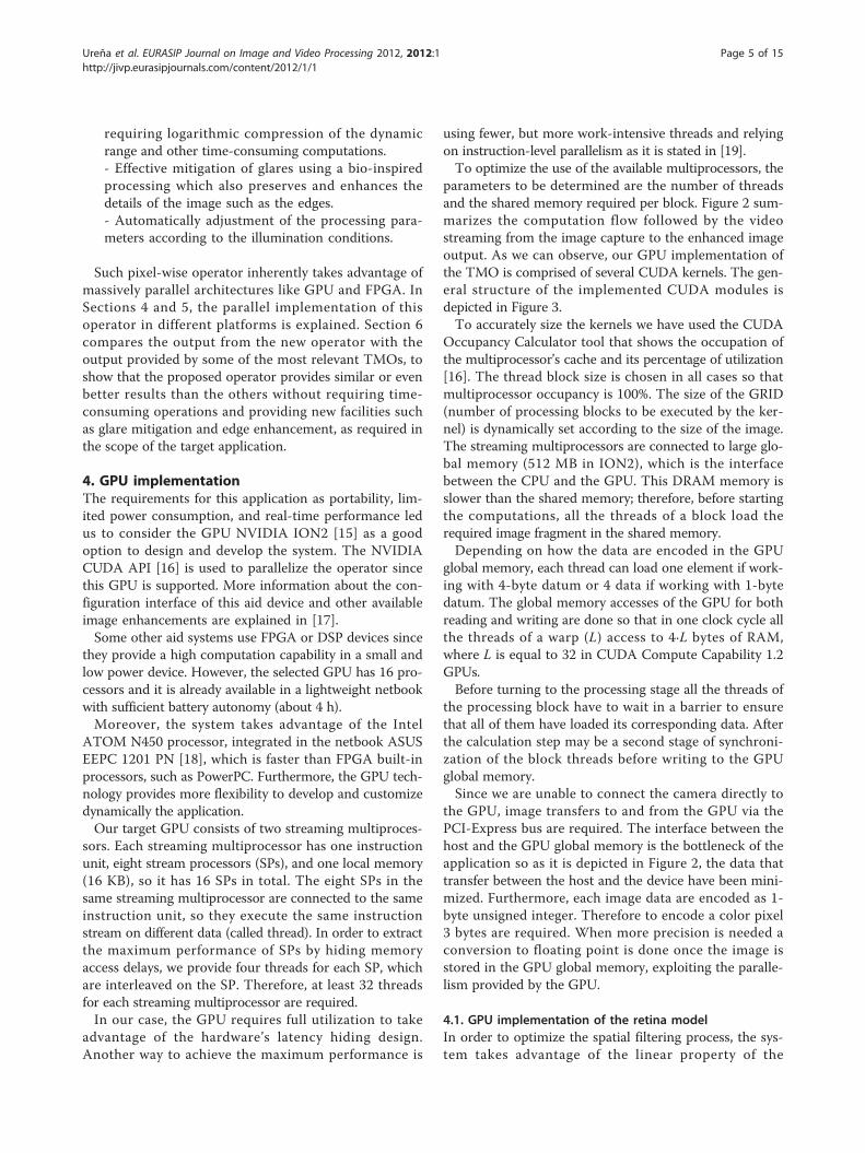
requiring logarithmic compression of the dynamicrange and other time-consuming computations.- Effective mitigation of glares using a bio-inspiredprocessing which also preserves and enhances thedetails of the image such as the edges.- Automatically adjustment of the processing para-meters according to the illumination conditions.
Such pixel-wise operator inherently takes advantage ofmassively parallel architectures like GPU and FPGA. InSections 4 and 5, the parallel implementation of thisoperator in different platforms is explained. Section 6compares the output from the new operator with theoutput provided by some of the most relevant TMOs, toshow that the proposed operator provides similar or evenbetter results than the others without requiring time-consuming operations and providing new facilities suchas glare mitigation and edge enhancement, as required inthe scope of the target application.
4. GPU implementationThe requirements for this application as portability, lim-ited power consumption, and real-time performance ledus to consider the GPU NVIDIA ION2 [15] as a goodoption to design and develop the system. The NVIDIACUDA API [16] is used to parallelize the operator sincethis GPU is supported. More information about the con-figuration interface of this aid device and other availableimage enhancements are explained in [17].Some other aid systems use FPGA or DSP devices since
they provide a high computation capability in a small andlow power device. However, the selected GPU has 16 pro-cessors and it is already available in a lightweight netbookwith sufficient battery autonomy (about 4 h).Moreover, the system takes advantage of the Intel
ATOM N450 processor, integrated in the netbook ASUSEEPC 1201 PN [18], which is faster than FPGA built-inprocessors, such as PowerPC. Furthermore, the GPU tech-nology provides more flexibility to develop and customizedynamically the application.Our target GPU consists of two streaming multiproces-
sors. Each streaming multiprocessor has one instructionunit, eight stream processors (SPs), and one local memory(16 KB), so it has 16 SPs in total. The eight SPs in thesame streaming multiprocessor are connected to the sameinstruction unit, so they execute the same instructionstream on different data (called thread). In order to extractthe maximum performance of SPs by hiding memoryaccess delays, we provide four threads for each SP, whichare interleaved on the SP. Therefore, at least 32 threadsfor each streaming multiprocessor are required.In our case, the GPU requires full utilization to take
advantage of the hardware’s latency hiding design.Another way to achieve the maximum performance is
using fewer, but more work-intensive threads and relyingon instruction-level parallelism as it is stated in [19].To optimize the use of the available multiprocessors, the
parameters to be determined are the number of threadsand the shared memory required per block. Figure 2 sum-marizes the computation flow followed by the videostreaming from the image capture to the enhanced imageoutput. As we can observe, our GPU implementation ofthe TMO is comprised of several CUDA kernels. The gen-eral structure of the implemented CUDA modules isdepicted in Figure 3.To accurately size the kernels we have used the CUDA
Occupancy Calculator tool that shows the occupation ofthe multiprocessor’s cache and its percentage of utilization[16]. The thread block size is chosen in all cases so thatmultiprocessor occupancy is 100%. The size of the GRID(number of processing blocks to be executed by the ker-nel) is dynamically set according to the size of the image.The streaming multiprocessors are connected to large glo-bal memory (512 MB in ION2), which is the interfacebetween the CPU and the GPU. This DRAM memory isslower than the shared memory; therefore, before startingthe computations, all the threads of a block load therequired image fragment in the shared memory.Depending on how the data are encoded in the GPU
global memory, each thread can load one element if work-ing with 4-byte datum or 4 data if working with 1-bytedatum. The global memory accesses of the GPU for bothreading and writing are done so that in one clock cycle allthe threads of a warp (L) access to 4·L bytes of RAM,where L is equal to 32 in CUDA Compute Capability 1.2GPUs.Before turning to the processing stage all the threads of
the processing block have to wait in a barrier to ensurethat all of them have loaded its corresponding data. Afterthe calculation step may be a second stage of synchroni-zation of the block threads before writing to the GPUglobal memory.Since we are unable to connect the camera directly to
the GPU, image transfers to and from the GPU via thePCI-Express bus are required. The interface between thehost and the GPU global memory is the bottleneck of theapplication so as it is depicted in Figure 2, the data thattransfer between the host and the device have been mini-mized. Furthermore, each image data are encoded as 1-byte unsigned integer. Therefore to encode a color pixel3 bytes are required. When more precision is needed aconversion to floating point is done once the image isstored in the GPU global memory, exploiting the paralle-lism provided by the GPU.
4.1. GPU implementation of the retina modelIn order to optimize the spatial filtering process, the sys-tem takes advantage of the linear property of the
Ureña et al. EURASIP Journal on Image and Video Processing 2012, 2012:1http://jivp.eurasipjournals.com/content/2012/1/1
Page 5 of 15
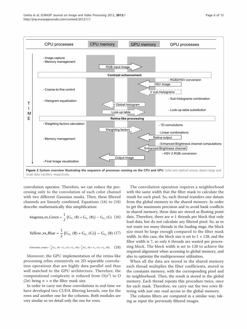
convolution operator. Therefore, we can reduce the pro-cessing only to the convolution of each color channelwith two different Gaussian masks. Then, these filteredchannels are linearly combined. Equations (16) to (18)describe mathematically this simplification:
Magenta vs Green =12
(Gσ1 (R) + Gσ1 (B)
) − Gσ2 (G) (16)
Yellow vs Blue =12
(Gσ1 (R) + Gσ1 (G)
) − Gσ2 (B) (17)
Achromatic output =13
(Gσ1 (R) + Gσ1 (G) + Gσ1 (B)
)−13
(Gσ2 (R) + Gσ2 (G) + Gσ2 (B)
) (18)
Moreover, the GPU implementation of the retina-likeprocessing relies extensively on 2D separable convolu-tion operations that are highly data-parallel and thuswell matched to the GPU architecture. Therefore, thecomputational complexity is reduced from O(n2) to O(2n) being n × n the filter mask size.In order to carry out these convolutions in real-time we
have developed two CUDA filtering kernels, one for therows and another one for the columns. Both modules arevery similar so we detail only the one for rows.
The convolution operation requires a neighborhoodwith the same width that the filter mask to calculate theresult for each pixel. So, each thread transfers one datumfrom the global memory to the shared memory. In orderto get the maximum precision and to avoid bank conflictsin shared memory, these data are stored as floating pointdata. Therefore, there are n-1 threads per block that onlyload data, but do not calculate any filtered pixel. So, as tonot waste too many threads in the loading stage, the blocksize must be large enough compared to the filter maskwidth. In this case, the block size is set to 1 × 128, and thefilter width is 7, so only 6 threads are wasted per proces-sing block. The block width is set to 128 to achieve therequired alignment when accessing to global memory, andalso to optimize the multiprocessor utilization.When all the data are stored in the shared memory
each thread multiplies the filter coefficients, stored inthe constants memory, with the corresponding pixel andits neighborhood. Then, the result is stored in the globalmemory. Each thread repeats this procedure twice, oncefor each mask. Therefore, we carry out the two rows fil-tering with just one read access to the global memory.The column filters are computed in a similar way, tak-
ing as input the previously filtered images.
- RGB2HSV conversion
- Sub-histograms combination
- Look-up-table substitution
- 1D convolutions
- Linear combinations
- Enhanced Brightness channel computations
- HSV 2 RGB conversion
- Coarse-to-fine control
- Histogram equalization
- Image capture- Memory management
TIME
Contrast enhancement
Retina-like processing
RGB input image
Look-up table
V Global histogram
Weighting factors
Retina output
GPU memoryCPU processes CPU memory GPU memory
V sub-histograms
GPU processes
HSV image
- Weighting factors calculation
- Memory management
- Final Image visualization
Enhanced Brightness channel
Output image
Figure 2 System overview illustrating the sequence of processes running on the CPU and GPU. Solid and dashed arrows depict large andsmall data transfers, respectively.
Ureña et al. EURASIP Journal on Image and Video Processing 2012, 2012:1http://jivp.eurasipjournals.com/content/2012/1/1
Page 6 of 15

Once the filtering process is finished we just need tolinearly combine partial results as we have explainedearlier, exploiting the parallelism provided by the GPUto obtain a gray level image. This image will be used tomodulate the degree of enhancement applied to thebrightness channel.
4.2. HSV conversion and brightness equalizerThis kernel uses thread blocks with size 256 (64 rows and4 columns) and 4 KB of shared memory to store thenecessary pixels and the histogram of the block. Accord-ing to the NVIDIA CUDA Occupancy calculator, theoccupancy of the multiprocessor is 100% and the maxi-mum number of active blocks per multiprocessor is 4.First of all, each block loads 1024 pixels in the GPU
shared memory, each thread loads four data. Once allthe data are stored in shared memory each thread com-putes three converted pixels and stores them in shared
memory. During the process, each block calculates itsown histogram of the brightness channel. To avoid mis-takes when calculating the histogram we use the atom-icAdd operation available in GPUs with CUDACompute Capability 1.2. Finally, we transfer the HSVpixels to the GPU global memory and we merge eachsub-histogram in a global histogram using atomic opera-tion. This way the brightness histogram is computed atthe same time the RGB to HSV conversion is performedrequiring only an additional transfer of each block histo-gram from shared to global memory. Then, the histo-gram equalization is performed using a LUTsubstitution obtaining a new brightness channel (V2 inFigure 1), which is linearly combined with the outputfrom the retina-like processing.Finally, de HSV to RGB conversion is performed in a
similar way, and the RGB resulting image is transferred tothe CPU.
SHARED MEM.
GLOBAL MEM. TO SHARED
SYNCHRONIZATION
PROCESSING
GLOBAL MEM.GLOB
SYNCHRONIZATION
4 data/hebra4K data/warp
1-byte data 4-byte data
1 datum/thread4K data/warp
4 data/hebra4K data/warp
Figure 3 General structure of the developed GPU modules.
Ureña et al. EURASIP Journal on Image and Video Processing 2012, 2012:1http://jivp.eurasipjournals.com/content/2012/1/1
Page 7 of 15

5. FPGA implementationOur target FPGA platform is the SB video-processingmobile platform [20], which includes a Xilinx Spartan 3XC3S2000 FPGA with 2 million gates, 36-Mbit SRAMmemory for data exchange, and all the interfacesrequired for the video input channel and the video out-put for HMD. We have chosen this platform because ofits reduced power consumption, and small size. Itincludes a battery that provides up to 10 h of autonomy.Figure 4 summarizes the processing carried out over
the video frames, from the image grabbing stage to theenhanced image output.The analog video input is passed to an analog-to-digital
converter, which encodes each pixel in YUV format. Inorder to separate the two different clock domains (theinput working at 27 MHz and the VGA output at40 MHz) we have used a double buffering technique.So, as to maximize the performance of the system and
to exploit the inherent parallelism on the programmabledevice selected for the implementation we chose a pipe-lined architecture, able to process a pixel every clockcycle.As in the previous section, we have implemented two
main procedures, the retina-like filtering and the bright-ness equalization. In the next sections, we explain each ofthese modules in detail, as well as the HSV conversionmodule, which requires a specific implementation adaptedto the FPGA.
5.1. Implementation of the retina-like filteringThe convolution process requires a set of pixels of itsneighborhood to calculate each pixel as we have explainedbefore. To resolve this problem we use the convolutioncomputation architecture proposed by Ridgeway [21],depicted in Figure 5. In order to use 7 × 7 filtering maskswe need 7 FIFO buffers that store the first 7 image rowsand seven shift registers that are responsible for storingthe 49 neighboring pixels for the current convolution. Theserial connection of the FIFO memories emulates the ver-tical displacement of the mask and the transfer of valuesof the FIFO memories to the shift registers emulates thehorizontal scrolling. Then, the accumulators marked as
“ACCUM x” add those pixels that are multiplied by thesame coefficients of the mask. We have six products as aresult of breaking down the process of convolution takingadvantage of the linear property of the convolution as wehave mentioned before. Then, we have to take intoaccount the weighting to be applied according to the per-centage of dark pixels present in the image.
5.2. HSV conversionThe calculation of the Hue component (H) requires com-plex computation. To avoid that, it has been implemen-ted using a LUT with 215 inputs of 8-bits each onemapped into the FPGA BlockRAM modules. This LUTemploys a 36% of the available memory (262 Kbits).Besides, to get the other two color components, satura-tion (S) and brightness (V), two dividers have been imple-mented. The design of the dividers is fully pipelined, andthey can achieve a throughput of one division per clockcycle. The division of the S component needs a fractionalremainder because the minimum of R, G, and B always isequal or less than the sum of them. This fact results inan 18-cycle delay which has to be considered in the Hcomponent computation in order to get synchronization.
5.3. Brightness equalizerTo implement the brightness equalizer the whole V colorplane, whose size is 640 × 480 pixels, the image is dividedin 35 blocks with 100 × 100 pixels and their cumulativedistributions are calculated. While the cumulative distri-butions for the current frame are being computed in par-allel, its brightness channel is being equalized using thedistributions computed for the previous frame. The dis-tributions computation is performed in five steps, calcu-lating seven distributions in parallel at each step, asimage is being scanned. This procedure finishes when the35 cumulative distribution functions are stored in theRAM memory. To develop the equalizer we rely exten-sively in the implementations explained in [10].
6. ResultsRegarding to the results provided by the proposedoperator, Figure 6 shows the output from the different
READMODULE
FIFO (DATA)
FIFO (ADRESS)
SRAMCONTROL
SRAM
RGB TO HSVCONVERTER
RETINAFILTER
INTENSITYEQUALIZER
LINEARCOMBINATION
HSV TO RGBCONVERTER
OUTPUT RGB
SAA7113HAD CONVERTER
INPUTVIDEO
GRAY LEVELCOMPUTER
Figure 4 Computation flow for the input images from the camera in the SB platform.
Ureña et al. EURASIP Journal on Image and Video Processing 2012, 2012:1http://jivp.eurasipjournals.com/content/2012/1/1
Page 8 of 15

processing stages. Figure 6a shows a dark image [22] inwhich main features of the scene cannot be appreciated,only the window can be distinguished. Figure 6b showsthe output from the retina-like filtering, as the wholeimage is too dark, the retina output mainly enhancesthe edges of the main features. Figure 6c shows the out-put brightness equalization without taking into accountthe retina output. The final output image is depicted inFigure 6d. As we can observe in this image, main fea-tures of the scene can be distinguished clearly whereasthe glares and the too bright areas which appear in Fig-ure 6c have been mitigated. Moreover, the colors of thepicture do not appear distorted.Figures 7 and 8 show a comparative of the output of our
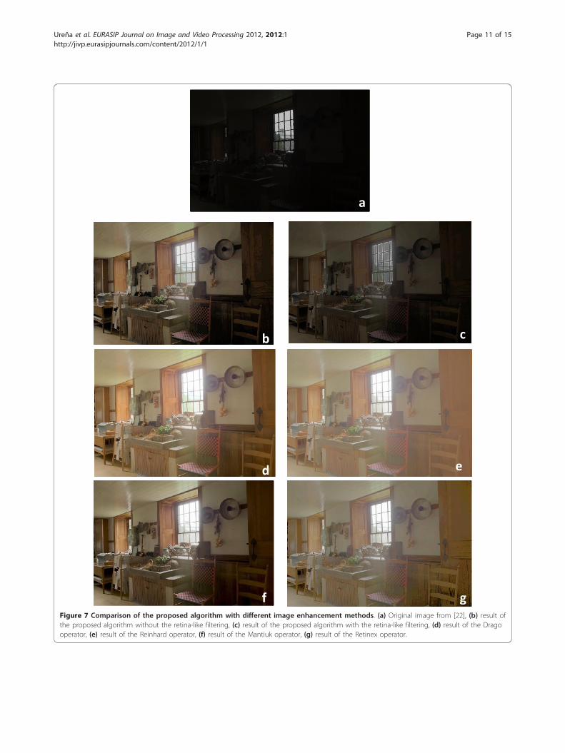
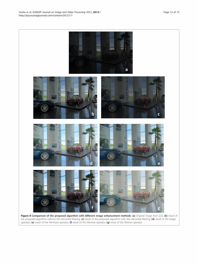
operator, without taking into account the retina-like pro-cessing, and the output from well-known TMOs and con-trast enhancement algorithms known as Drago et al. [5],Mantiuk et al. [23], and Reinhard and Devlin [24] opera-tors and Multiscale Retinex [8]. As we have explained pre-viously, our operator has two main stages, one comprisinga dynamic range adaptation and contrast enhancementand a second one for glare mitigation and edge enhance-ment. The later is specially designed for low-vision-affected people; therefore, the output obtained from thecombination of both parts is not directly comparable withthe output from other TMO operators. For this reason, wehave set aside the output from the retina-like processingin this comparative.
In Figure 7a, we can observe the same underexposedimage than in Figure 6[22]. Figure 7b-g shows the origi-nal image enhanced with different TMO algorithms. InFigure 7b, we can observe perfectly all the elements ofthe image, actually the proposed operator not onlybrighten dark region, but also keep details of the land-scape out of the window, whereas the output from theother TMOs presents the window overexposed (see Fig-ure 7d-g), and, in some cases, the whole image appearstoo bright (see Figure 7e, g). Figure 8 shows anothercomparative example. In this case, the original image pre-sents better signal-to-noise ratio (SNR) than in the pre-vious case, according to Table 1. As we can observe, theproposed algorithm enhances the whole image withoutsaturating the bright regions and preserves the overalllevel of illumination in medium values, that way all thedetails can be appreciated without presenting disturbingglares.Table 1 summarizes the SNR of each of the images
presented in Figures 7 and 8.The value of the SNR has been calculated according to
Equation (19):
SNR = 20log(μ
σ
)(19)
Where μ is the average value of the image and s isthe standard deviation. We are working with color
FIFO
FIFO
FIFO
FIFO
SHIFT REGISTER
SHIFT REGISTER
SHIFT REGISTER
SHIFT REGISTER
…
ACCUM X 2
ACCUM X 16
ACCUM X 50
…
…
…
RED_09ACCUM
RED _1.2ACCUM
COMBINATION
2
16
50
24 bits (RGB)
GRAY LEVEL
ACCUM X 1
ACCUM X 7
ACCUM X 28
…
1
7
28
MASK 1
MASK 2
GREEN_09ACCUM
BLUE_09ACCUM
GREEN _1.2ACCUM
BLUE _1.2ACCUM
WEIGHT DECISION
Figure 5 Convolution diagram for the FPGA.
Ureña et al. EURASIP Journal on Image and Video Processing 2012, 2012:1http://jivp.eurasipjournals.com/content/2012/1/1
Page 9 of 15

images so we show in Table 1 the average value of theSNR calculated for each channel.From these comparisons of the results with different
methods we can observe that the proposed algorithmprovides an effective improvement of dark images andhigh-contrast images, without altering color information,preserving the details, and it does not brighten exces-sively the image. Moreover, it can enhance the imageautomatically according to the lighting conditions, with-out requiring the user to set complicated parameters.According to the measures of the SNR presented in
Table 1, our operator is able to increase the SNR withrespect to the original image. Moreover, the values ofthe SNR provided by our algorithm are pretty similar tothe values provided by the others TMOs, especially tothe Drago operator. This operator is the one which pro-vides more natural scenes and better detail reproductionin dark regions, according to a study performed byYoshida et al. [25]. In this study, the authors conduct apsychophysical experiment based on a direct compari-son between the appearances of real-world HDR imagesof these scenes displayed on a low dynamic range moni-tor employing seven well-known TMOs. The human
subjects were asked to rate image naturalness, overallcontrast, overall brightness, and detail reproduction indark and bright image regions with respect to the corre-sponding real-world scene.Moreover, as it can be observed from Figures 7 and 8,
the proposed operator provides better detail reproduc-tion in bright image regions (observe the window inFigure 7a, b).At this point, we discuss the results obtained from
tests regarding the performance of the system using theGPU and the FPGA-based platforms, and also related tothe use of resources for the FPGA implementation, andthe speed up obtained with respect to a non-parallelCPU implementation.As we have mentioned before, the complete system
have been implemented on a GPU NVIDIA ION2 andon an FPGA Xilinx Spartan 3. The results regardingarea occupation and clock frequency for the FPGAimplementation are summarized in Table 2.Table 3 summarizes the performance in frames per
second (fps) of the CPU (Matlab code running on a sin-gle core), GPU, and FPGA implementations of the newoperator and the speed up obtained with respect to the
a b
c dFigure 6 Outputs from the different stages of the proposed operator: (a) original image [22], (b) output from the retina-like filtering,(c) output from the contrast-enhancement processing, and (d) final image.
Ureña et al. EURASIP Journal on Image and Video Processing 2012, 2012:1http://jivp.eurasipjournals.com/content/2012/1/1
Page 10 of 15
a
b c
d e
f gFigure 7 Comparison of the proposed algorithm with different image enhancement methods. (a) Original image from [22], (b) result ofthe proposed algorithm without the retina-like filtering, (c) result of the proposed algorithm with the retina-like filtering, (d) result of the Dragooperator, (e) result of the Reinhard operator, (f) result of the Mantiuk operator, (g) result of the Retinex operator.
Ureña et al. EURASIP Journal on Image and Video Processing 2012, 2012:1http://jivp.eurasipjournals.com/content/2012/1/1
Page 11 of 15
(f) (g)
a
b c
d e
f g
Figure 8 Comparison of the proposed algorithm with different image enhancement methods. (a) Original image from [22], (b) result ofthe proposed algorithm without the retina-like filtering, (c) result of the proposed algorithm with the retina-like filtering, (d) result of the Dragooperator, (e) result of the Reinhard operator, (f) result of the Mantiuk operator, (g) result of the Retinex operator.
Ureña et al. EURASIP Journal on Image and Video Processing 2012, 2012:1http://jivp.eurasipjournals.com/content/2012/1/1
Page 12 of 15

CPU when working with RGB images with VGA resolu-tion (640 × 480). The CPU used to carry out this testsis the CPU Intel core i7 920 at 2.67 GHz. Both GPUand FPGA implementations reach real-time perfor-mance, over 25 fps, obtaining a minimum speed up of7.5 with respect to the CPU even when using a high-end CPU.The FPGA performs at a major frame rate than the
GPU. This is mainly due to the large delay required totransfer the frame from the CPU memory to the GPUglobal memory and vice versa (10 ms). Neverthelessfurther improvement can be achieved by performing thetransferences between the CPU and the GPU asynchro-nously, concurrently with computation.However, the GPU works in floating point precision,
whereas the FPGA uses fixed point since it has nonative support for floating point arithmetic. Also theGPU computes the histogram with 256 intensity levelsinstead of the 64 levels employed by the FPGA, which islimited by routing constrains.To measure the accuracy of both approaches we have
calculated the peak-signal-to-noise ratio (PSNR), of theoutput image obtained with both, GPU and FPGA, sys-tems with respect to the one obtained with the CPU,according to Equation (20). The resulting image com-puted with the FPGA obtains a PSNR of 30 dB, whereaswith the GPU the value of the PSNR is infinite since theoutput image is identical to the one obtained with theCPU. The FPGA obtains a lower value for the PSNR asa result of the different algorithmic simplifications thathad to be adopted, and the use of fixed point arithmetic.
PSNR = 10log10
⎛⎜⎝ MAX2
I1mn
∑m−1i=0
∑n−1j=0 [I(i, j) − K(i, j)]2
⎞⎟⎠ (20)
where I stands for the resulting image obtained withthe CPU, K is the resulting image obtained with theGPU or the FPGA, m and n are de dimensions of theimage and MAXI is the maximum value that a pixel canreach (255 in our case).Table 4 details the percentage of the total processing
time employed in each of the tasks by the GPU and bythe FPGA. In the case of the FPGA, the percentage oftime is obtained for each module separately, when thewhole system is working, all the tasks are being executedin a pipeline. On the other hand, the GPU employs onlya 6% of the processing time in the histogram adjustment,since the histogram calculation is performed in parallelwith the RGB to HSV conversion. Moreover, more than30% of the time is employed in performing image trans-fers from CPU memory to GPU memory, so furtherimprovement can be achieved performing the memorystorage in parallel with the computation. Table 5 sum-marizes the power consumption, clock frequency, andweight for both systems.According to the tables presented, we can observe that
real-time performance (over 25 fps) is reached with bothembedded solutions. Nevertheless the FPGA implemen-tation is an order of magnitude more power efficientthan the GPU, although it provides less accuracy in thecomputations and therefore output images with lessPSNR.On the other hand, the FPGA solution is less weight,
whereas the GPU solution is more affordable since itsuse is widely extended. In the case of the GPU, a fixedarchitecture is provided and the goal is to obtain its max-imum performance, whereas an FPGA design leavesmore choices to the engineer. This flexibility of theFPGA comes at the cost of a much larger design timethan the GPU and makes tuning the system more diffi-cult than in the case of the GPU.
7. ConclusionsHigh-end GPUs and FPGAs are suitable for highly par-allel complex algorithms such as pixel-wise processing.
Table 1 SNR obtained with different TMOs
Original(dB)
Proposed operator without theretina-like output (dB)
Proposed operator with the retina-like output (dB)
Drago(dB)
Reinhard(dB)
Mantiuk(dB)
Retinex(dB)
Kitchenscene
-3.28 18.48 16.18 18.18 20.70 12.36 18.52
Car scene 9.53 20.77 18.52 21.01 18.3 13.96 23.2
Table 2 Area and speed for the whole system on aSpartan 3 XC3S2000
Parameter Value
Slices 16545 (80%)
LUTs 30086 (73%)
RAMB 39 (97%)
Fmax 40.25 MHz
MULTs 26 (65%)
BUFGMUXs 7 (87%)
DCMs 2 (50%)
Table 3 Performance of GPU and FPGA implementations,frame size 640 × 480
CPU GPU FPGA
Performance (fps) 4 30 60
Speed up - 7.5 15
Ureña et al. EURASIP Journal on Image and Video Processing 2012, 2012:1http://jivp.eurasipjournals.com/content/2012/1/1
Page 13 of 15

On the other hand, limited resources GPUs and FPGAs,with less computing capability and reduced power con-sumption, can compete with other embedded solutionsin portable applications which also require image pro-cessing parallel computation to achieve real-timeperformance.We have presented two implementations of a new
TMO on a GPU NVIDIA ION2 integrated in a smallsize netbook and on a Spartan 3 FPGA-based platformreaching in both cases real-time performance whenworking with 640 × 480 RGB images. The FPGA imple-mentation provides higher frame rates and less powerconsumption, whereas the GPU implementation pro-vides more precision in the computation and thereforehigher quality output images.Since both implementations use portable and battery-
operated platforms they can be used as low-vision aids spe-cially aimed at visually impaired people, such as thoseaffected by Retinitis Pigmentosa, who present several diffi-culties to manage themselves in environments where illumi-nation is not uniform or in low illumination environments.
AcknowledgementsThis study was supported by the Junta de Andalucía Project P06-TIC-02007,the Spanish National Grants AP2010-4133, RECVIS (TIN2008-06893-C03-02)and DINAM-VISION (DPI2007-61683), the project GENIL-PYR-2010-19 fundedby CEI BioTIC GENIL CEB09-0010, and the Special Research Programme ofthe University of Granada.
Competing interestsThe authors declare that they have no competing interests.
Received: 7 April 2011 Accepted: 15 February 2012Published: 15 February 2012
References1. Irawan P, Ferwerda JA, Marschner SR: Perceptually based tone mapping of
high dynamic range image streams. Paper presented at the EurographicsSymposium on Rendering Konstanz, Germany; 2005, 231-242.
2. Hu K-J, Lu M-Y, Wang J-C, Hsu T-I, Chang T-T: Using adaptive tonemapping to enhance edge-preserving color image automatically.EURASIP J Image Video Process 2010, Article ID 137134, 11 (2010).doi:10.1155/2010/137134.
3. Cope B, Cheung P, Luk W, Howes L: Performance comparison of graphicsprocessors to reconfigurable logic: a case study. IEEE Trans Comput 2010,59:433-448.
4. Pauwels K, Tomasi M, Alonso Diaz J, Ros E, Van Hulle MM: A comparison ofFPGA and GPU for real-time phase-based optical flow, stereo, and localimage features. IEEE Trans Comput .
5. Drago F, Myszkowsky K, Annen T, Chiba N: Adaptative logarithmicmapping for displaying high contrast scene. Paper presented at theComputer Graphics Forum 2003, 22:419-426.
6. Ward-Larsen GW, Rushmeier H, Piatko C: A visibility matching tonereproduction operator for high dynamic range scenes. IEEE Trans VisComput Graph 1997, 3(4):291-306.
7. Zhao H, Jin X, Shen J: Real-time tone mapping for high-resolution HDRimages. Paper presented at the 2008 International Conference on CyberworldsHangzhou, China; 2008, 256-262.
8. Rahman Z, Jobson DJ, Woodell GA, Hines GD: Image enhancement, imagequality, and noise. Proc SPIE 2005, 59070N, doi:10.1117/12.619460.
9. Horiuchi T, Tominaga S: HDR image quality enhancement based onspatially variant retinal response. EURASIP J Image Video Process 2010,Article ID 438958, 11 (2010). doi:10.1155/2010/438958.
10. Reza AM: Realization of the contrast limited adaptive histogramequalization (CLAHE) for real-time image enhancement. J VLSI SignalProcess 2004, 38:35-44.
11. Pelayo FJ, Romero S, Morillas C, Martínez A, Ros E, Fernández E: Translatingimage sequences into spike patterns for cortical neuro-stimulation.Neurocomputing 2004, 58-60:885-892.
12. Morillas C, Romero S, Martínez A, Pelayo F, Reyneri L, Bongard M,Fernández E: A neuroengineering suite of computational tools for visualprostheses. Neurocomputing 2007, 70(16-18):2817-2827.
13. Morillas C, Cobos JP, Pelayo FJ, Prieto A, Romero S: VIS2SOUND onreconfigurable hardware. 2008 International Conference on ReconfigurableComputing and FPGAs Cancún, México; 2008, 205-210.
14. Sekuler R, Blake R: Perception. McGraw-Hill international editions; 1994.15. 2011, GPU NVDIA ION 2. http://www.nvidia.com/object/
picoatom_specifications.html.16. NVIDIA Corporation: NVIDIA CUDA C Programming Best Practices Guide
2.3. 2009.17. Ureña R, Martínez-Cañada P, Gómez-López JM, Morillas C, Pelayo F: A
portable low vision aid based on GPU. Paper presented at FirstInternational Conference on Pervasive and Embedded Computing andCommunication Systems. PECCS 2011 Vilamoura, Portugal; 2011, 201-206.
18. 2011, Asus EEPC 1201 PN. http://www.asus.com/product.aspx?P_ID=N0JLbhfgdnpw5FaY.
Table 4 Percentage of time per frame spent on each processing stage
Processing stage % time/frame
GPU FPGA
Store image in device memory 15.6 32.54
RGB to HSV conversion 30.2 10.53
Histogram adjustment 6.64 18.37
Retina-like processing 14.22 9.13
Lineal combination 6.01 2.09
HSV to RGB conversion 12.31 27.34
Store image in main memory 15.02 -
Table 5 Comparison of the employed platforms in terms of power consumption, clock frequency, and weight
Platform Power (W) Proc. clock (MHz) Mem. clock (MHz) Weight (kg)
ASUS EEPC 1201PN [18] 12 450 750 1.45
SB video-processing mobile platform [20] 0.9 40 27 0.5
Ureña et al. EURASIP Journal on Image and Video Processing 2012, 2012:1http://jivp.eurasipjournals.com/content/2012/1/1
Page 14 of 15

19. Volkov V: Prologue Quarterly Of The National Archives. 2010, available athttp://people.sc.fsu.edu/~gerlebacher/gpus/better_performance_at_lower_occupancy_gtc2010_volkov.pdf.
20. SB platform: 2011 [http://www.sevensols.com/index.php?seccion=262&subseccion=270].
21. Ridgeway D: Designing Complex 2-Dimensional Convolution Filters. Theprogrammable Logic DataBook, Xilinx; 1994.
22. 2011, The HDR Photografic Survey, http://www.cis.rit.edu/fairchild/HDR.html.
23. Mantiuk R, Tomaszewska A, Heidrich W: Color correction for tonemapping. Computer Graphics Forum 2009, 28(2):193-202.
24. Reinhard E, Devlin K: Dynamic range reduction inspired by photoreceptorphysiology. IEEE Trans Visual Comput Graph 2005, 11(1):13-24.
25. Yoshida A, Blanz V, Myszkowski K, Seidel HP: Perceptual evaluation of tonemapping operators with real-world scenes. Paper presented at IS&T/SPIE’s17th Annual Symposium Electronic Imaging San Jose, CA, USA; 2005,192-203.
doi:10.1186/1687-5281-2012-1Cite this article as: Ureña et al.: Real-time tone mapping on GPU andFPGA. EURASIP Journal on Image and Video Processing 2012 2012:1.
Submit your manuscript to a journal and benefi t from:
7 Convenient online submission
7 Rigorous peer review
7 Immediate publication on acceptance
7 Open access: articles freely available online
7 High visibility within the fi eld
7 Retaining the copyright to your article
Submit your next manuscript at 7 springeropen.com
Ureña et al. EURASIP Journal on Image and Video Processing 2012, 2012:1http://jivp.eurasipjournals.com/content/2012/1/1
Page 15 of 15