research open access systematic construction, … · systematic construction, verification and...
TRANSCRIPT

RESEARCH Open Access
Systematic construction, verification andimplementation methodology for LDPC codesHui Yu*, Jing Cui, Yixiang Wang and Yibin Yang
Abstract
In this article, a novel and systematic Low-density parity-check (LDPC) code construction, verification andimplementation methodology is proposed. The methodology is composed by the simulated annealing based LDPCcode constructor, the GPU based high-speed code selector, the ant colony optimization based pipeline schedulerand the FPGA-based hardware implementer. Compared to the traditional ways, this methodology enables us toconstruct both decoding-performance-aware and hardware-efficiency-aware LDPC codes in a short time. Simulationresults show that the generated codes have much less cycles (length 6 cycles eliminated) and memory conflicts(75% reduction on idle clocks), while having no BER performance loss compared to WiMAX codes. Additionally, thesimulation speeds up by 490 times under float precision against CPU and a net throughput 24.5 Mbps is achieved.Finally, a net throughput 1.2 Gbps (bit-throughput 2.4 Gbps) multi-mode LDPC decoder is implemented on FPGA,with completely on-the-fly configurations and less than 0.2 dB BER performance loss.
Keywords: low-density parity-check codes, simulated annealing, ant colony optimization, graphic processing unit,decoder architecture
1. IntroductionLow-density parity-check (LDPC) code is first proposedby Gallager [1] and rediscovered by Mackay and Nealsince they introduce Tanner Graph [2] into LDPC code[3]. LDPC code with soft decoding algorithms on TannerGraph can achieve outstanding capacity and approachShannon limit over noisy channels at moderate decodingcomplexity [4]. Most algorithms root from the famousbelieve propagation (BP) algorithm, such as min-sumalgorithm (MSA) with simplified calculation, modifiedMSA (MMSA) [5] with improved BER performance andlayered versions [6] with fast decoding convergence.The existence of “cycle” in Tanner Graph is a critical
constraint of the above algorithms, as it breaks the“message independence hypothesis” and degrades theBER performance. As a result, “girth” becomes an impor-tance metric of estimating the performance of the LDPCcode. The progressive edge-growth (PEG) algorithm [7]is a girth-aware construction method that tries to makeshortest cycle as large as possible. Approximate cycleextrinsic (ACE) message degree constraint is further
combined into PEG [8] to lower error floor. However,these performance-aware methods do not take hardwareimplementation into account, which usually result in lowefficiency or high complexity.As to the decoder implementation, the fully-parallel
architecture [9] is first proposed for achieving the highestdecoding throughput, but the hardware complexity due tothe routing overhead is very high. The semi-parallellayered decoder [10] is then proposed to achieve the trade-off between hardware complexity and decoding through-put. Memory conflict is a critical problem for layereddecoder, which is modeled as a single-layer traveling sales-man problem (TSP) in [11]. However, this model ignores“element permutation”, i.e., the order assignment of theedges in each layer, and its search does not cover the entiresolution space. Further, fully-parallel graphic processingunit (GPU) based implementation is also proposed in [12].In this article, a novel and systematic LDPC code con-
struction, verification, and implementation methodologyis proposed, and a software and hardware platform isimplemented, which is composed by four modules asshown in Figure 1. The simulated annealing (SA) basedLDPC code constructor continuously constructs goodcandidate codes. The BER performance of the generated
* Correspondence: [email protected] of Electronic Engineering, Shanghai Jiao Tong University,Shanghai, P. R. China
Yu et al. EURASIP Journal on Wireless Communications and Networking 2012, 2012:84http://jwcn.eurasipjournals.com/content/2012/1/84
© 2012 Yu et al; licensee Springer. This is an Open Access article distributed under the terms of the Creative Commons AttributionLicense (http://creativecommons.org/licenses/by/2.0), which permits unrestricted use, distribution, and reproduction in any medium,provided the original work is properly cited.
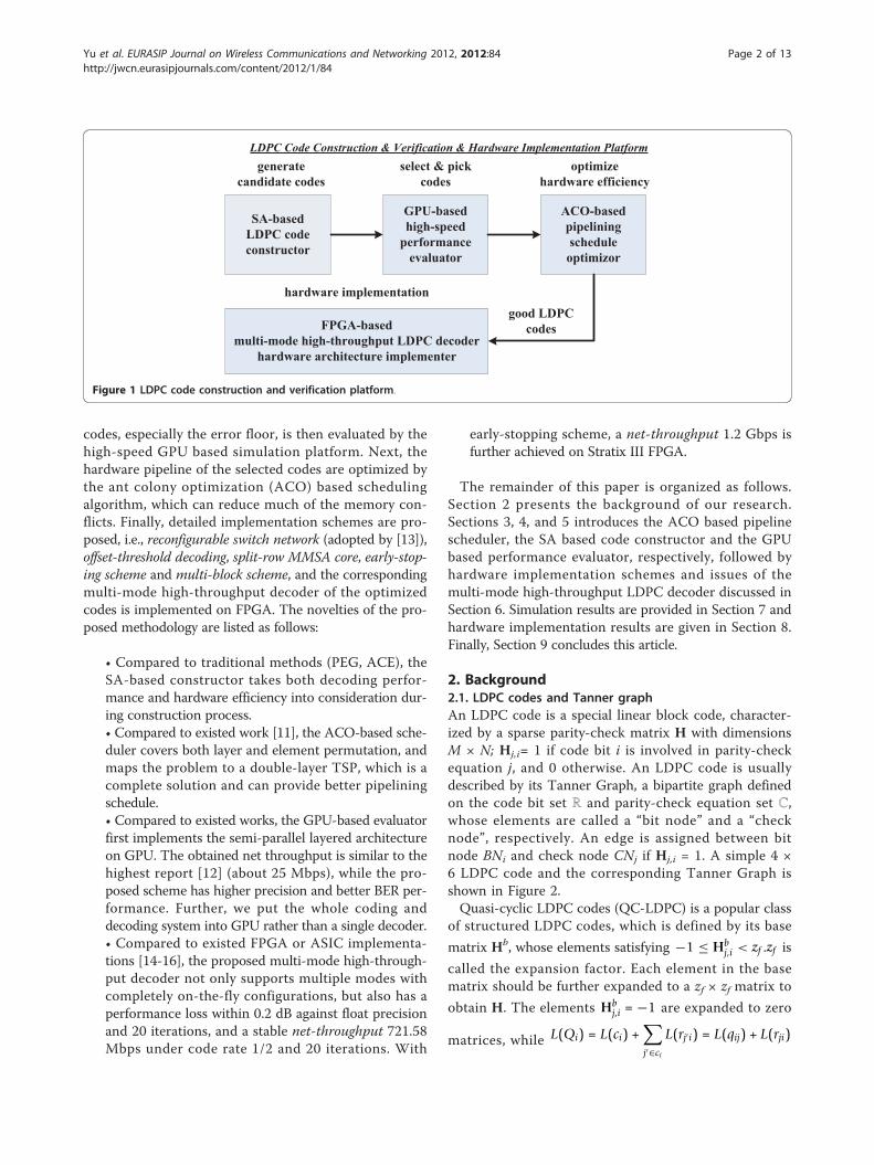
codes, especially the error floor, is then evaluated by thehigh-speed GPU based simulation platform. Next, thehardware pipeline of the selected codes are optimized bythe ant colony optimization (ACO) based schedulingalgorithm, which can reduce much of the memory con-flicts. Finally, detailed implementation schemes are pro-posed, i.e., reconfigurable switch network (adopted by [13]),offset-threshold decoding, split-row MMSA core, early-stop-ing scheme and multi-block scheme, and the correspondingmulti-mode high-throughput decoder of the optimizedcodes is implemented on FPGA. The novelties of the pro-posed methodology are listed as follows:
• Compared to traditional methods (PEG, ACE), theSA-based constructor takes both decoding perfor-mance and hardware efficiency into consideration dur-ing construction process.• Compared to existed work [11], the ACO-based sche-duler covers both layer and element permutation, andmaps the problem to a double-layer TSP, which is acomplete solution and can provide better pipeliningschedule.• Compared to existed works, the GPU-based evaluatorfirst implements the semi-parallel layered architectureon GPU. The obtained net throughput is similar to thehighest report [12] (about 25 Mbps), while the pro-posed scheme has higher precision and better BER per-formance. Further, we put the whole coding anddecoding system into GPU rather than a single decoder.• Compared to existed FPGA or ASIC implementa-tions [14-16], the proposed multi-mode high-through-put decoder not only supports multiple modes withcompletely on-the-fly configurations, but also has aperformance loss within 0.2 dB against float precisionand 20 iterations, and a stable net-throughput 721.58Mbps under code rate 1/2 and 20 iterations. With
early-stopping scheme, a net-throughput 1.2 Gbps isfurther achieved on Stratix III FPGA.
The remainder of this paper is organized as follows.Section 2 presents the background of our research.Sections 3, 4, and 5 introduces the ACO based pipelinescheduler, the SA based code constructor and the GPUbased performance evaluator, respectively, followed byhardware implementation schemes and issues of themulti-mode high-throughput LDPC decoder discussed inSection 6. Simulation results are provided in Section 7 andhardware implementation results are given in Section 8.Finally, Section 9 concludes this article.
2. Background2.1. LDPC codes and Tanner graphAn LDPC code is a special linear block code, character-ized by a sparse parity-check matrix H with dimensionsM × N; Hj,i= 1 if code bit i is involved in parity-checkequation j, and 0 otherwise. An LDPC code is usuallydescribed by its Tanner Graph, a bipartite graph definedon the code bit set ℝ and parity-check equation set ℂ,whose elements are called a “bit node” and a “checknode”, respectively. An edge is assigned between bitnode BNi and check node CNj if Hj,i = 1. A simple 4 ×6 LDPC code and the corresponding Tanner Graph isshown in Figure 2.Quasi-cyclic LDPC codes (QC-LDPC) is a popular class
of structured LDPC codes, which is defined by its base
matrix Hb, whose elements satisfying −1 ≤ Hbj,i < zf .zf is
called the expansion factor. Each element in the basematrix should be further expanded to a zf × zf matrix to
obtain H. The elements Hbj,i = −1 are expanded to zero
matrices, while L(Qi) = L(ci) +∑j′∈ci
L(rj′i) = L(qij) + L(rji)
Figure 1 LDPC code construction and verification platform.
Yu et al. EURASIP Journal on Wireless Communications and Networking 2012, 2012:84http://jwcn.eurasipjournals.com/content/2012/1/84
Page 2 of 13

are expanded to a cyclic-shift identity matrices with per-
mutation factors Hbj,i ≥ 0 . QC-LDPC is naturally avail-
able for layered algorithms, whose j-th row is exactly
layer j. We call the “1"s of j-th row as the set p = Hbj,i .
See Figure 3 for an example of a 4 × 6 base matrix withzf = 4.
2.2. The BP algorithm and effect of cycleThe BP algorithm is a general soft decoding scheme forcodes described by Tanner Graph. It can be viewed asthe process of iterative message exchange between bitnodes and check nodes. For each iteration, each bitnode or check node collects the messages passed fromits neighborhood, updates its own message and passesthe updated message back to its neighborhood. BP algo-rithm has many modified versions, such as log-domainBP, MSA, and layered BP. All of them originate fromthe basic log-domain message passing equations, givenas follows.
{Hbj,i
∣∣∣Hbj,i ≥ 0} (1)
L(qij) = L(Qi) − L(rji) (2)
L(Qi) = L(ci) +∑j′∈ci
L(rj′i) = L(qij) + L(rji) (3)
where L(ci) is the initial channel message, L(qij) is themessage passing from BNi to CNj, L(rji) is the messageof inverse direction, and L(Qi) is the a-posteriori of bitnode BNi. Ci is the neighbor set of BNi, ℛj is the
neighbor set of CNj. �(x) = logex + 1ex − 1
. These equations
can also be applied in layered BP, the difference is thatthe L(qij) and L(rji) should be updated in each layer ofthe iteration.The above equations requires the independence of all
the messages L( qi′j), i′ Î ℛj and Hbj,k . However, the
existence of “cycle” in Tanner Graph invalidates thisindependence assumption, thus degrades the BER per-formance of BP algorithm. A length 6 cycle is shownwith bold lines in Figure 2. In this case, if BP algorithmproceeds for more than three iterations, the receivemessages of the involved bit nodes v2,v4,v5 will partlycontain its own message sent three iterations before. Forthis reason, the minimum cycle length in the TannerGraph, called “girth”, has a strong relationship with itsBER performance, and is considered as an importantmetric in LDPC code construction algorithms (PEG,ACE) [7,8].
2.3. Decoder architecture and memory conflictThe semi-parallel structure with layered MMSA core isa popular decoder architecture due to its good tradeoffamong low complexity, high BER performance and highthroughput. As shown in Figure 4, the main compo-nents in the top-level architecture include an LLRSUMRAM storing L(Qi), an LLREX RAM storing L(rji) and alayered MMSA core pipeline. The two RAMs should bereadable and writable. Old values of L(Qi) and L(rji) areread, and new values are calculated through the pipelineand written back to RAMs. For QC-LDPC codes, thevalues are processed layer by layer, and the “1"s in eachlayer is processed one by one.Memory conflict is a critical problem that constrains
the throughput of the semi-parallel decoder. Essentially,memory conflict occurs when the read-after-write(RAW) dependency of L(Qi) is violated. Note that thenew value of L(Qi) will not be written back to RAMuntil the pipelined calculation finishes. If L(Qi) is againneeded during this calculation period, the old value willbe read, while the new one is still under processing, seeL(Q6) in Figure 4. This case happens when the layers jand j + l have “1"s in the same position
i (Hbj,i ≥ 0,Hb
j+l,i ≥ 0) . We call it a gap-l conflict.
Memory conflict slows the decoding convergence andthus reduces the BER performance. The traditionalmethod of handling memory conflict is to insert idleclocks in the pipeline, with the cost of throughputreduction. It’s obvious that the smaller l, the more idleclocks should be inserted, since the pipeline need towait at least K stages before writing back the newvalues. Usually, the number of gap-1, gap-2, gap-3
Figure 2 H matrix and Tanner Graph of LDPC.
Figure 3 A simple 4 × 6 base matrix Hb with zf = 4.
Yu et al. EURASIP Journal on Wireless Communications and Networking 2012, 2012:84http://jwcn.eurasipjournals.com/content/2012/1/84
Page 3 of 13

conflicts, denote c1, c2 and c3, are considered as themetrics of measuring memory conflict.
3. The ACO-based pipelining schedulerIn this section, we propose the ACO-based pipelinescheduling algorithm to minimize memory conflict. Wefirst formulate this problem, then map it to the double-layered TSP and finally use ACO to solve it.
3.1. Problem formulationConsider a QC LDPC code described by its base matrixH with dimensions M × N. Thus, there are M layers.Denote wm,1 ≤ m ≤ M as the number of elements ("1"s)in m-th layer. Denote hm,n, 1 ≤ n ≤ wm as the columnindex in H of the n-th element, m-th layer. Additionally,we assume the core pipeline is K stages.As discussed above, the decoder processes all the “1"s
in H exactly once by processing layer-by-layer in eachiteration, and element-by-element in each layer. How-ever, the order can be arbitrary, which enables us toschedule the elements carefully to minimize memoryconflict. We have two ways to solve it.
• Layer permutation: We can assign which layer tobe processed first and which to be next. If two layersi,j have 1s at totally different positions, i.e., such j,ldo not exist that hi,k = hj,l, they tend to be assignedas the adjacent layers with no conflict.• Element permutation: In a certain layer, we canassign which element to be processed first andwhich to be next. If two adjacent layers i,j still haveconflict, i.e., hi,k = hj,l for some k,l, then we canassign element k to be first in layer i, and l to be lastin layer j. By this way, we increase the time intervalbetween the conflicting elements k and l.
Therefore, the memory conflict minimization problemis exactly a scheduling problem, in which layer permuta-tion and element permutation should be designed tominimize the number of idle pipeline clock insertions.We denote layer permutation as m ® lm, 1 ≤ m, lm ≤
M, and element permutation of layer m as n ® µm,n, 1≤ n,µm,n ≤ wm.Based on the above definitions, a memory conflict
occurs between layer i, element k and layer j, element l ifthe following conditions are satisfied: (1) layers i,j areassigned to be adjacent, i.e., lj = li + 1; (2) hi,k = 1 and hj,l = 1; (3) the pipeline time interval is less than pipelinestages, i.e., wi−µi,k+µj,l ≤ K. Further, we define the “conflictset” C as C(i, j) = {(k, l)|elements (i,k) and (j, l) cause amemory conflict}, and the “conflict stages”, also the mini-mum number of idle clocks inserted due to this conflict, as
c(i, k; j, l) = max{K − (wi − μi,k + μj,l), 0} (4)
3.2. The double-layered TSPThis part introduces the mapping from the above memoryconflict minimization problem to a double-layered TSP.TSP is a famous NP-hard problem, in which the salesmanshould find the shortest path to visit all the n cities exactlyonce and finally return to the starting point. Denote di,j asthe distance between city i and city j. TSP can be mathe-matically described as follows: given distance matrix D =[di,j]n×n, find the optimal permutation of the city indicesx1,x2, ...,xn to minimize the loop distance,
min
(n−1∑i=1
dxi,xi+1 + dxn ,x1
)(5)
Compared to layer permutation which can contributemost part of the memory conflict reduction, elementpermutation only deals with minor changes for the opti-mization when layer permutation is already determined.Therefore, we map the problem to a double-layeredTSP, where layer permutation is mapped to the firstlayer, and element permutation is mapped to the secondlayer based on result of the first layer. Details aredescribed as follows:
• Layer permutation layer: In this layer we only dealwith layer permutation. We define the “distance”,
Figure 4 The layered MMSA decoder architecture and memory conflict.
Yu et al. EURASIP Journal on Wireless Communications and Networking 2012, 2012:84http://jwcn.eurasipjournals.com/content/2012/1/84
Page 4 of 13

also “cost” between layers i and j as the minimumnumber of idle clocks inserted before the processingof layer j. If more conflict position pairs exist, i.e.,∣∣C(i, j)∣∣ > 1 , then we should take the maximum
one. Thus in this layer, the distance matrix shouldbe defined by
di,j = max(k,l)εC(i,j)
C(i, k; j, l) (6)
and the target function remains the same as (5).• Element permutation layer: In this layer we inheritthe layer permutation result, and map element per-mutation of each layer to an independent TSP. In theTSP for layer i, we fix the schedule of the prior layerp (lp = li − 1) and next layer q (lq = li + 1), and onlytune the elements of layer i. We define the “distance”dk,l as the change on the number of idle clocks if ele-ment k is assigned to the position l, i.e., µi,k = l. Notethat element k can conflict with layer p or q, and dk,lvaries by different conflict cases, given by
dk,l =
⎧⎪⎨⎪⎩0 both conflict or neither conflict
k − l k only conflict with layer p
l − k k only conflict with layer q
(7)
Since the largest dk,l becomes the bottleneck of ele-ment permutation, the target function should changeto the following max form:
min max{dx1,x2 , dx2,x3 , . . . , dxn−1,xn , dxn ,x1} (8)
3.3. The ACO-based algorithmThis part introduces the ACO based algorithm to solvethe double-layered TSP discussed above. ACO is a heuris-tic algorithm to solve computational problems which canbe reduced to finding good paths through graphs. Its ideaoriginates from mimicking the behavior of ants seeking apath between their colony and a source of food. ACO isespecially suitable for solving TSP.Algorithm 1 [see Additional file 1] gives the ACO-
based double-layered memory conflict minimizationalgorithm. First we try layer permutation LAYER1_MAXtimes, and for each layer permutation, we try elementpermutation for LAYER2_MAX times. We record thepipeline schedule with smallest idle clocks as the bestsolution for this algorithm.The detailed ACO algorithm for TSP is described in
Algorithm 2. We try SOL_MAX solutions, and for eachsolution, all ants should finish CYCLE_MAX cycles, in
which the shortest cycle is recorded as the best solution.One ant cycle is finished in VERTEX_NUM ant-movesteps, where one step is consist of four sub-steps: AntChoose, Ant Move, Local Update and Global Update.Further, the Bonus is rewarded to the shortest cycle. Allspecific parameters (e.g., p and �) are referred to thesuggestion of [17].
4. The SA-based code constructorIn this section, we propose a joint optimized construc-tion algorithm that takes both performance and effi-ciency into consideration during construction the Hmatrix of the LDPC code. We first give the SA basedframework and then discuss the details of the algorithm.
4.1. Problem formulationWe now deal with the classic code construction pro-blem. Given the code length N, code rate R, and perhapsother constraints such as QC-RA type (e.g., WiMAX,DVB-S2), or fixed degree distribution (optimized bydensity evolution), we should construct a “good” LDPCcode described by its H matrix that meets practicalneed. The word “good” here mainly have the followingtwo metrics.
• High performance, which means the code shouldhave high coding gain and good BER/BLER perfor-mance, including early water-fall region, low errorfloor and anti-fading ability. This is strongly relatedto large girth, large ACE spectrum, few trappingsets, and etc.• High efficiency, which means the implementation ofthe encoder and decoder should have moderate com-plexity, and high throughput. This is strongly relatedto QC-RA type, high degree of parallelism, shortdecoding pipeline, few memory conflicts, and etc.
Traditional construction methods mainly focus onhigh performance of the code, such as PEG and ACE,which motivates us to find a joint optimized construc-tion method concerning both performance andefficiency.
4.2. The double-stage SA frameworkIn this part, we introduce the double-stage SA [18]based framework for the joint optimized constructionproblem. SA is a generic probabilistic metaheuristic forthe global optimization problem which should locate agood approximation to the global optimum of a givenfunction in a large search space. Since our search spaceis a large 0-1 matrix space, denoted as {0, 1}M×N, SA isvery useful for this problem.Note that the performance metric is the more impor-
tant metric for LDPC construction compared with
Yu et al. EURASIP Journal on Wireless Communications and Networking 2012, 2012:84http://jwcn.eurasipjournals.com/content/2012/1/84
Page 5 of 13

efficiency metric. Therefore, we divide the algorithminto two stages, aiming at performance and efficiency,respectively, and regard performance as the major stagethat should be satisfied first. For a specific target mea-sured by “performance energy” e1 and “efficiencyenergy” e2, we set two thresholds: upper bound e1h = e1,and lower bound e1l <e1. The algorithm enters in thesecond stage when the current performance energy isless than e1l. At the second stage, the algorithm ensuresthe performance energy to be not larger than e1h, andtry to reduce the e2. Algorithm 3 shows the details.
4.3. Details of the algorithmThis part discusses the details of the important func-tions and configurations of Algorithm 3.
• sample_temperature is the temperature samplingfunction, decreasing with k. It can be an exponentialform ae−bk.• prob is the accept probability function of the newsearch point h_new. If h_new is better (E_new <E), itreturns 1, otherwise, it decreases with E_new−E, andincreases with t. It can be an exponential form ae−b
(E_new−E)/t• perf_energy is the performance energy function. Itevaluates the performance related factors of thematrix h, and gives a lower energy for better perfor-mance. Typically, we can calculate the number oflength-l cycles cl, then calculate a total cost given by∑l wlcl, where wl is the cost weight of a length-lcycle, decreasing with l.• effi_energy is the efficiency energy function, similaras perf_energy except that it gives a lower energy forhigher efficiency. Typically, we can calculate the thenumber of gap-l memory conflicts cl, then calculatea total cost given by ∑l wlcl, where wl is the costweight of a layer gap l conflict, decreasing with l.• perf_neighbor searches for a neighbor of h in thematrix space when aiming at performance, which isbased on minor changes of h. For QC LDPC, we candefine three atomic operations for the base matrixHb as follows.
- Horizontal swap: For chosen row i,j and col-
umn k, l, swap values of Hbi,k and Hb
i,l , then
swap values of Hbj,k and Hb
j,l .
- Vertical swap: For chosen row i,j and column k,
l, swap values of Hbi,k and Hb
j,k , then swap values
of Hbi,l and Hb
j,l .
- Permutation change: Change the permutation
factor for chosen element Hbi,k .
For a higher temperature t, we allow the neighborsearching process to search in a wider space. This isdone by performing the atomic operations moretimes.• effi_neighbor searches for a neighbor of h in thematrix space when aiming at efficiency. This is simi-lar as perf_neighbor, however, typically we shouldremove the permutation change operation, as it doesnothing to help reduce conflicts.
5. The GPU-based performance evaluatorIn this section, we introduce the implementation ofhigh-speed LDPC verification platform based on com-pute unified device architecture (CUDA) supportedGPUs. We first give the architecture and algorithm onGPU, and then talk about some details.
5.1. Motivation and architectureCompute unified device architecture is NVIDIA’s parallelcomputing architecture. It enables dramatic increases incomputing performance by executing multiple parallelindependent and cooperated threads on GPU, thus isparticularly suitable for the Monte Carlo model. The BERsimulation of LDPC code is Monte Carlo since it collectshuge amount of bit error statistics of the same decodingprocess, especially in the error floor region when the BERis low (10−7 to 10−10). This motivates us to implementthe verification platform on GPU where many decodersrun parallel like hardware such as ASIC/FPGA to providestatistics.Figure 5 shows our GPU architecture. CPU is used as
the controller, which puts the code into GPU constantmemory, raises the GPU kernels and gets back the sta-tistics. While in GPU grid, we implement the wholecoding system for each GPU block, including sourcegenerator, LDPC encoder, AWGN channel, LDPC deco-der and statistics. Our decoding algorithm is layeredMMSA. In each GPU block, we assign zf threads to cal-culate new LLRSUM and LLREX of the zf rows in eachlayer, where zf is the expansion factor of QC LDPC. Thezf threads cooperate to complete the decoding job.
5.2. Algorithm and procedureThis part introduces the procedure that implements theGPU simulation, given by Algorithm 4. P × Q blocks runparallel, each simulating an individual coding system,where P is the number of multiprocessors (MP) on thedevice and Q is the number of cores per MP. In each sys-tem, zf threads cooperatively do the job of encoding,channel and decoding. When decoding, the threads pro-cess data layer after layer, each thread performing
Yu et al. EURASIP Journal on Wireless Communications and Networking 2012, 2012:84http://jwcn.eurasipjournals.com/content/2012/1/84
Page 6 of 13

LMMSA for one row of this layer. The procedure endsup with the statistics of P × Q LDPC blocks.
5.3. Details and instructions• Ensure “coalesced access” when reading or writingglobal memory, or the operation will be auto-serial-ized. In our algorithm, the adjacent threads shouldaccess adjacent L(Qi) and L(rji).• Shared memory and registers are fast yet limitedresources and their use should be carefully planned. Inour algorithm, we store L(Qi) in shared memory and L(rji) in registers due to the lack of resources.• Make sure all the P × Q cores are running. This callsfor careful assignment of limited resources (i.e., warps,shared memory, registers). In our case, we limit theregisters per thread to 16 and threads per block to128, or some of the Q cores on each MP will “starve”and be disabled.
6. Hardware implementation schemes6.1. Top-level hardware architectureOur goal is to implement a multi-mode high-throughputQC-LDPC decoder, which can support multiple code ratesand expansion factors on-the-fly. The proposed decoderconsists of three main parts, namely, the interface part, theexecution part and the control part. The top level architec-ture is shown in Figure 6.The interface part buffers the input and output data as
well as handling the configuration commands. In theexecution part, the LLRSUM and LLREX are read outfrom the RAMs, updated in the Σ parallel LMMSA cores,and written back to the RAMs, thus forming theLLRSUM loop and the LLREX loop, as marked red inFigure 6. The control part generates control signals,including port control, LLRSUM control, LLREX controland iteration control.
Note that the reconfigurable switch network is designedin the LLRSUM loop to support multi-mode feature. As toachieve high-throughput, we propose the split-row MMSAcore, the early-stopping scheme and the multi-blockscheme. The split-row core has two data inputs and twodata outputs, hence it also “splits” the LLRSUM RAM andLLREX RAM into two parts, meanwhile, two identicalswitch networks are needed to shuffle the data simulta-neously. We also propose the offset-threshold decodingscheme to improve BER/BLER performance. The abovefive techniques are described in detail as follows.
6.2. The reconfigurable switch networkA switch network is an S-input, S-output hardware struc-ture that can put the input signals in the arbitrary order atthe output. Formally, given input signals x1,x2,...,xS withdata width W, the output of switch network has the formxa1 , xa2 , ..., xaS where a1,a2,...,aS is any desired permutationof 1,2,...,S. For the design of reconfigurable LDPC deco-ders, two special kinds of output order are more impor-tant, described as follows.
• Full cyclic-shift: The output has the cyclic-shiftform of the total S inputs, i.e., xc, xc+1,...xS, x1,x2...,xc−1, where 1 ≤ c ≤ S.• Partial cyclic-shift: The output has the cyclic-shiftform of the first p inputs, while other signal can bein arbitrary order, i.e., i.e., xc, xc+1,...xp, x1,x2...,xc−1,x*,...x*, where 1 ≤ c<p <S, and x* can be any signalfrom xp+1 to xS.
For the implementation of QC-LDPC decoder, theswitch network is an essential module. Suppose
Hbj,i �= Hb
k,i ≥ 0, j < k , and for any j < l < k, Hbl,i = −1 ,
then the same data is involved in the processing of theabove two “1"s, i.e., LLRSUM and LLREX of BNi × Zf to
Figure 5 GPU architecture of the BER simulation for LDPC code.
Yu et al. EURASIP Journal on Wireless Communications and Networking 2012, 2012:84http://jwcn.eurasipjournals.com/content/2012/1/84
Page 7 of 13

BN(i+1) × zf−1. However, after processing Hbj,i , the above
data should be cyclic-shifted to ensure correct order for
the processing Hbj,k which corresponds to the full cyclic-
shift case with
S = zf , c = (Hvk,i − Hb
j,i + S) mod S (9)
Further, in the case of multiple expansion factors,such as WiMAX [19] (zf = 24: 4: 96), the partial cyclic-shift is required with
S = zmaxf , p = zf , c = (Hb
k,i − Hbj,i + p) mod p (10)
The existing schemes to implement switch networksinclude the MS-CS network [20] and Benes network[13,21,22]. The former structure can handle the casewhen S is not a power of 2, while the latter is provedmore efficient in area and gate count. In [13], the mostefficient on-the-fly generation method of control signalsis proposed. Therefore, we adopt the Benes networkproposed in [13] for our decoder. The structure isshown in Figure 7 and the features is given in Table 1.
6.3. The offset-threshold decoding schemeIn this part, we propose the offset-threshold decodingmethod, which is adopted in our decoder architecture.Unlike existed modifications of MSA [5], the proposedscheme uses an offset-threshold correction to furtherimprove the BER/BLER performance.The traditional MSA is a simplified version of BP, by
replacing the complicated Equation (2) with simple minoperation, shown as follows.
sgn (L(rji)) =
⎛⎝ ∏
i′∈Rj\i
sgn (L(qi′ j))
⎞⎠ (11)
abs(L(rji)) = mini′∈Rj\i
(∣∣L(qi′j)∣∣) (12)
In [5], the normalized and offset MMSA schemes (13)(14) are proposed to compensate the loss of the aboveapproximation, described as follows.
abs(L(rji)) = α · abs(L(rji)) (13)
abs(L(rji)) = max (abs(L(rji)) − β , 0) (14)
In our simulation, for BLER, the offset MMSA per-forms better than normalized one. However, as to BER,both schemes show error floor at 10−6, as shown inFigure 8. The problem here is that, for most cases, theoffset MMSA works well, while in a few cases, thedecoding fails with many bit errors in one block. Theintuitive explanation of such phenomenon is existenceof extremely large likelihoods (L(qij), L(rji)). In high SNRregion, the L(qij) likelihoods converge fast to a largevalue, for both correct and wrong bits in some cases.The wrong bits not only remain wrong, but also propa-gate large L(rji) to other bits, resulting in more wrongbits and finally failure of decoding. For this reason, weneed to set threshold upon offset MMSA to limit thelikelihoods of becoming extremely large, which leads tothe proposed offset-threshold scheme, done by the fol-lowing equation.
Figure 6 Top-level multi-mode high-throughput LDPC decoder architecture.
Yu et al. EURASIP Journal on Wireless Communications and Networking 2012, 2012:84http://jwcn.eurasipjournals.com/content/2012/1/84
Page 8 of 13
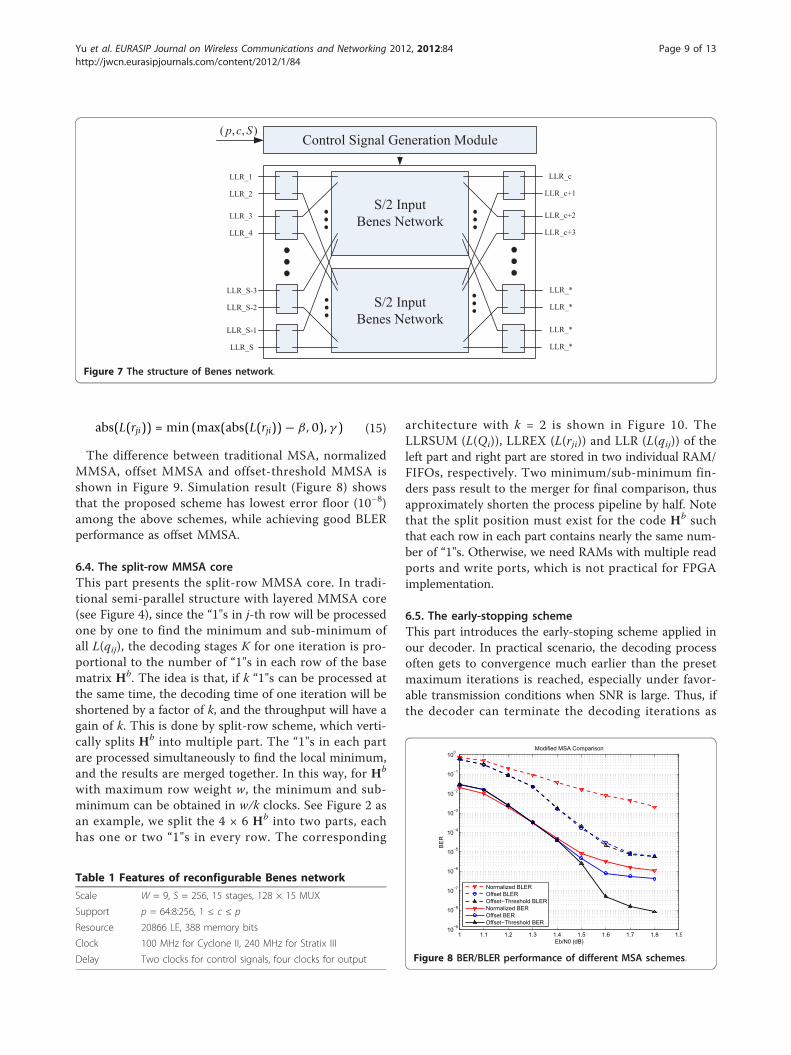
abs(L(rji)) = min (max(abs(L(rji)) − β , 0), γ ) (15)
The difference between traditional MSA, normalizedMMSA, offset MMSA and offset-threshold MMSA isshown in Figure 9. Simulation result (Figure 8) showsthat the proposed scheme has lowest error floor (10−8)among the above schemes, while achieving good BLERperformance as offset MMSA.
6.4. The split-row MMSA coreThis part presents the split-row MMSA core. In tradi-tional semi-parallel structure with layered MMSA core(see Figure 4), since the “1"s in j-th row will be processedone by one to find the minimum and sub-minimum ofall L(qij), the decoding stages K for one iteration is pro-portional to the number of “1"s in each row of the basematrix Hb. The idea is that, if k “1"s can be processed atthe same time, the decoding time of one iteration will beshortened by a factor of k, and the throughput will have again of k. This is done by split-row scheme, which verti-cally splits Hb into multiple part. The “1"s in each partare processed simultaneously to find the local minimum,and the results are merged together. In this way, for Hb
with maximum row weight w, the minimum and sub-minimum can be obtained in w/k clocks. See Figure 2 asan example, we split the 4 × 6 Hb into two parts, eachhas one or two “1"s in every row. The corresponding
architecture with k = 2 is shown in Figure 10. TheLLRSUM (L(Qi)), LLREX (L(rji)) and LLR (L(qij)) of theleft part and right part are stored in two individual RAM/FIFOs, respectively. Two minimum/sub-minimum fin-ders pass result to the merger for final comparison, thusapproximately shorten the process pipeline by half. Notethat the split position must exist for the code Hb suchthat each row in each part contains nearly the same num-ber of “1"s. Otherwise, we need RAMs with multiple readports and write ports, which is not practical for FPGAimplementation.
6.5. The early-stopping schemeThis part introduces the early-stoping scheme applied inour decoder. In practical scenario, the decoding processoften gets to convergence much earlier than the presetmaximum iterations is reached, especially under favor-able transmission conditions when SNR is large. Thus, ifthe decoder can terminate the decoding iterations as
Figure 7 The structure of Benes network.
Table 1 Features of reconfigurable Benes network
Scale W = 9, S = 256, 15 stages, 128 × 15 MUX
Support p = 64:8:256, 1 ≤ c ≤ p
Resource 20866 LE, 388 memory bits
Clock 100 MHz for Cyclone II, 240 MHz for Stratix III
Delay Two clocks for control signals, four clocks for output
1 1.1 1.2 1.3 1.4 1.5 1.6 1.7 1.8 1.910−9
10−8
10−7
10−6
10−5
10−4
10−3
10−2
10−1
100
Eb/N0 (dB)
BE
R
Modified MSA Comparison
Normalized BLEROffset BLEROffset−Threshold BLERNormalized BEROffset BEROffset−Threshold BER
Figure 8 BER/BLER performance of different MSA schemes.
Yu et al. EURASIP Journal on Wireless Communications and Networking 2012, 2012:84http://jwcn.eurasipjournals.com/content/2012/1/84
Page 9 of 13

soon as it detect the convergence, the power of the cir-cuit can be reduced as well as the decoding delay.Throughout is also increased if the system dynamicallyadjusts the transmission rate according to statistics ofaverage iteration numbers under current channel state.Traditional stopping criterions focus on whether the
code can be decoded successfully or not, which either costtoo much extra resource to store iteration parameters,such as HDA [23] and NSPC [24], or use floating-pointcalculation to evaluate the current iteration situation, suchas VNR [25] and CMM [23]. All these methods are notsuitable for the hardware implementation.Here, we propose a simple and effective scheme to
detect the convergence of the decoding. The “conver-gence” means at some time, all of the hard decisions sgn(L(Qi)) satisfy the check equations, The detection of con-vergence usually demands parallel calculation of eachequation, However, due to the layered structure (QC) andlack of the hardware resources, we can use a semi-parallel
algorithm to implement iteration-stopping module, whichevaluates one layer (zf equations) simultaneously. If thenumber of the continuously successful-check layers reacha threshold ω, the module will trigger a signal meaningthe decoding have got to convergence and the iterationcan be stopped.One important issue of Algorithm 5 is the estimation of
threshold ω. The BER/BLER performances and averageiteration times of different ω are shown in Figure 11,where the stopping criterion of ideal iteration is HcT = 0.We choose ω = 2.5 × M to achieve tradeoff between timeand performance. In this case, if the average iterationtimes is Iave (ideal iteration case), the decoding terminatesat approximately Iave + 2 iterations.
6.6. The multi-block schemeSuppose the LDPC code with code length N and expan-sion factor zf still has serious memory conflicts thoughbeing optimized by our SA and ACO algorithms, whichis common for large zf and relatively small N. Toaddress this problem, we propose a hardware methodcalled “multi-block” to further avoid memory conflictsand increase pipeline efficiency. The “multi-block”scheme is explain as follows.We construct a new matrix Hv by the parity-check
matrix H with M rows:
Hυ =(H 00 H
)(16)
Here “virtual matrix” Hv is the combination of twocodes H without “cross constraint” (edge between nodesfrom different codes in Tanner Graph) between eachother. Suppose v1, v2 are any two legal encoded blockssatisfying that
Figure 9 Comparison of the correction types of different MSAschemes.
Figure 10 The architecture of split-row MMSA core.
1 1.2 1.4 1.6 1.810−9
10−8
10−7
10−6
10−5
10−4
10−3
10−2
10−1
100
Eb/N0 (dB)
BE
R
BER in iteration termination
ω=2*Mω=2.5*Mω=3*MIdeal Iteration
1 1.2 1.4 1.6 1.88
10
12
14
16
18
20
Eb/N0 (dB)
Ave
rage
iter
atio
ns
Average iterations in termination
ω=2*Mω=2.5*Mω=3*MIdeal Iteration
Figure 11 BER/BLER performance and average iterations underdifferent ω.
Yu et al. EURASIP Journal on Wireless Communications and Networking 2012, 2012:84http://jwcn.eurasipjournals.com/content/2012/1/84
Page 10 of 13

v1.HT = 0 v2.HT = 0 (17)
Thus the vector (v1 v2) is also one legal block for Hv:
(v1 v2
).HT
υ =(v1 v2
).(HT 00 HT
)= 0 (18)
The key observation is that there are no memory con-flicts between the two codes H due to the diagonal formof Hv. This enables us to reorder and combine thedecoding schedule of the two codes to reduce memoryconflict of each code. We rewrite H and Hv as follows:
H =
⎛⎜⎝
H1...
HM
⎞⎟⎠ Hvopt =
⎛⎜⎜⎜⎜⎜⎜⎝
H(1)1 0
0 H(2)1
......
H(1)M 0
0 H(2)M
⎞⎟⎟⎟⎟⎟⎟⎠
(19)
where H(j)i
denotes the i-th row of the j-th code. The
decoding schedule is given by above equation, i.e., H(1)i
comes first, followed by H(2)i
, and then H(1)i+1
, and so on
so forth. The benefit of this “multi-block” scheme is that
the insertion of H(2)i
provides extra stages for the con-
flicts between H(1)i
and H(1)i+1
.
To sum up, the “multi-block” scheme changes any gap-l memory conflict to gap-(2l − 1), thus can improve thepipeline efficiency significantly. Meanwhile, it demandsno extra logic resources (LE) for the design, but maydouble the memory bits for buffering two encodedblocks. Since the depth of memory is not fully used onour FPGA, the proposed method can make full use of itwith no extra resource cost.
7. Numerical simulationIn this section, we show how our platform produces“good” LDPC codes with outstanding decoding perfor-mance and hardware efficiency. For comparison, we tar-get on the WiMAX LDPC code (N = 2304, R = 0.5, zf =96). We use the same parameters and degree distribu-tions as WiMAX for our SA-based constructor. We set“cycle” as performance metric and memory conflict asefficiency metric. The performance of one of the candi-date codes and the WiMAX code are listed in Table 2.The candidate code has much less length-6/8 cycles andgap-1/2/3 memory conflict. Usually, the candidate codescan eliminate length-6 cycles and gap-1 conflicts, whichensures a larger-than-or-equal-to 8 girth and no conflictunder short pipeline (when K ≤ wm).
We simulate the candidate code and WiMAX codethrough the GPU platform. The BER/BLER performanceis shown in Figure 12, while the platform parametersand throughput are listed in Table 3. The water-fallregion and the error floor of our candidate code isalmost the same as WiMAX code. For speed compari-son, we also include the fastest result that ever reported[12]. The “net throughput” is defined by the decoded“message bits” per second, given by:
net throughput =P · Q · N · R
t(20)
where t is the consumed time for running through theGPU kernel (for us is Algorithm 4). As shown in Table3, our GPU platform speeds up 490 times against CPUand achieves a net throughput 24.5 Mbps. Further, ourthroughput approaches the fastest one, while providingbetter precision (floating-point vs. 8 bit fixed-point) forthe simulation.Finally, we optimize the pipeline schedule by ACO-
based scheduler, shown in Table 2. The “pipeline occu-pancy” is given by running/total clocks required for oneiteration. For the candidate code, the number of idleclock insertions after ACO is 5, compared with 12before ACO, achieving a 58.3% reduction. While forWiMAX code, 20 idle clock insertions remain requiredafter layer-permutation-only (single-layer) scheme
Table 2 Cycle and conflict performance of the two codes
Candidate code WiMAX code
Cycle:length 6/8 0/55 5/150
Conflict:gap 1/2/3 0/3/9 5/11/15
Pipeline occupancy Before ACO: 76/88 Only layer
After ACO: 76/81 permu.: 76/96
1 1.2 1.4 1.6 1.8 2 2.2 2.4 2.610−8
10−7
10−6
10−5
10−4
10−3
10−2
10−1
100
Eb/N0 (dB)
BE
R
BER/BLER Performance: Candidate code vs WiMAX code
Candidate code BERCandidate code BLERWiMAX code BERWiMAX code BLER
Figure 12 BER and BLER performance of the two codes.
Yu et al. EURASIP Journal on Wireless Communications and Networking 2012, 2012:84http://jwcn.eurasipjournals.com/content/2012/1/84
Page 11 of 13

proposed by [11]. In this case, the double-layered ACOachieves a 75% reduction against the single-layer scheme(5 vs. 20 idle clocks).
8. The multi-mode high-throughput decoderBased on the above techniques, namely, reconfigurableswitch network, offset-threshold decoding, split-row MMSAcore, early-stoping scheme and multi-block scheme, weimplement the multi-mode high-throughput LDPC deco-der on Altera Stratix III FPGA. The proposed decodersupports 27 modes, including nine different code lengthsand three different code rates, and maximum 31 iterations.The configurations for code length, code rate, and itera-tion number are completely on-the-fly. Further, it has aBER gap less than 0.2 dB against floating-point LMMSA,while achieving a stable net-throughput 721.58 Mbpsunder code rate R = 1/2 and 20 iterations (correspondingto a bit-throughput 1.44 Gbps). With early-stopping mod-ule working, the net-throughput can boost up to 1.2 Gbps(bit-throughput 2.4 Gbps), which is calculated under aver-age 12 iterations. The features are listed in Table 4.One great advantage of the proposed multi-mode high-
throughput LDPC decoder is that more modes can besupported with only more memory bits consumed andno architecture level change. Since the reconfigurableswitch network supports all expansion factors zf ≤ 256,and the layered MMSA cores supports arbitrary QC-
LDPC codes, more code lengths and code rates are natu-rally supported, for example, the WiMAX codes (zf = 24:4: 96, R = 1/2, 2/3, 3/4, 5/6, 114 modes in total). Theonly cost is that more memory bits are required to storethe new base matrices Hb.
9. ConclusionIn this article, a novel LDPC code construction, verifica-tion, and implementation methodology is proposed, whichcan produce LDPC codes with both good decoding perfor-mance and high hardware efficiency. Additionally, a GPUverification platform is built that can accelerate 490×speed against CPU and a multi-mode high-throughputdecoder is implemented on FPGA, achieving a net-throughput 1.2 Gbps and performance loss within 0.2 dB.
Additional material
Additional file 1: Algorithm. This file contains Algorithm 1, Memoryconflict minimization algorithm; Algorithm 2, ACO algorithm for TSP;Algorithm 3, The SA based LDPC construction framework; Algorithm 4,The GPU based LDPC simulation; and Algorithm 5, Semi-parallel early-stopping algorithm.
AcknowledgementsThis paper is partially sponsored by the Shanghai Basic Research Key Project(No. 11DZ1500206) and the National Key Project of China (No. 2011ZX03001-002-01).
Competing interestsThe authors declare that they have no competing interests.
Received: 15 May 2011 Accepted: 6 March 2012Published: 6 March 2012
References1. R Gallager, Low-density parity-check codes. IRE Trans. Inf. Theory. 8(1),
21–28 (1962). doi:10.1109/TIT.1962.10576832. R Tanner, A recursive approach to low complexity codes. IEEE Trans. Inf.
Theory. 27(9), 533–547 (1981)3. D MacKay, Good error-correcting codes based on very sparse matrices. IEEE
Trans. Inf. Theory. 45(3), 399–431 (1999)4. T Richardson, M Shokrollahi, R Urbanke, Design of capacity approaching
irregular low-density parity-check codes. IEEE Trans. Inf. Theory. 47(2),619–637 (2001). doi:10.1109/18.910578
5. J Chen, RM Tanner, C Jones, L Yan Li, Improved min-sum decoding algorithmsfor irregular LDPC codes, in Proc. ISIT, (Adelaide, 2005), pp. 449–453
6. DE Hocevar, A reduced complexity decoder architecture via layereddecoding of LDPC codes, in IEEE workshop on SiPS, pp. 107–112 (2004)
7. Y Hu, E Eleftheriou, DM Arnold, Regular and irregular progressive edgegrowth Tanner graphs. IEEE Trans. Inf. Theory. 51(1), 386–398 (2005)
8. D Vukobratovic, V Senk, Generalized ACE constrained progressive Eedge-growth LDPC code design. IEEE Comm. Lett. 12(1), 32–34 (2008)
9. AJ Blanksby, CJ Howland, A 690-mW 1-Gb/s 1024-b, rate-1/2 low-densityparity-check code decoder. J. Solid State Circ. 37(3), 404–412 (2002).doi:10.1109/4.987093
10. Z Cui, Z Wang, Y Liu, High-throughput layered LDPC decoding architecture.IEEE Trans. VLSI Syst. 17(4), 582–587 (2009)
11. C Marchand, J Dore, L Canencia, E Boutillon, Conflict resolution forpipelined layered LDPC decoders, in IEEE workshop on SiPS, (Tampere, 2009),pp. 220–225
Table 3 Parameters and performance: GPU vs CPU (20iterations)
GPU (ours) CPU GPU [12]
Platform NV. GTX260 Intel Core2 Quad NV. 8800GTX
Clock frequency 1.24GHz 2.66 GHz 1.35 GHz
Decoding method Semi-parallel Semi-parallel Full-parallel
LMMSA LMMSA BP
Blocks×threads 216 × 96 1 128 × 256
Net throughput 24.5 Mbps 50 Kbps 25Mbps
Precision Floating-point Floating-point 8-bit fixed-point
Table 4 Features of the multi-mode high-throughputdecoder
FPGA platform Altera Stratix III EP3SL340F1517C2
Decoding scheme Layered offset-threshold MSA
Modes supported 9 × 3 = 27 modes
Code length N = 1536:768:6144 (zf = 64:32:256)
Code rate R = 1/2,2/3,3/4 (Hb :12 × 24, 8 × 24, 6 × 24)
Iteration number iter = 1−31, 20 recommended
Resources usage 149, 976 LE, 3, 157, 136 bits memory
BER performance gap ≤ 0.2 dB vs. 20 iteration float LMMSA
Clock setup 225.58MHz
Stable net throughput 721.58 Mbps (zf = 256, R = 1/2, iter = 20)
Max. net throughput 1.2 Gbps (early-stopping, iter = 12 ave.)
Yu et al. EURASIP Journal on Wireless Communications and Networking 2012, 2012:84http://jwcn.eurasipjournals.com/content/2012/1/84
Page 12 of 13

12. G Falcao, V Silva, L Sousa, How GPUs can outperform ASICs for fast LDPCdecoding, in Proc. international conf on Supercomputing, (New York, 2009),pp. 390–399
13. J Lin, Z Wang, Effcient shuffle network architecture and application forWiMAX LDPC decoders, in IEEE Trans. on Circuits and Systems. 56(3),215–219 (2009)
14. KK Gunnam, GS Choi, MB Yeary, M Atiquzzaman, VLSI architectures forlayered decoding for irregular LDPC codes of WiMax, in IEEE InternationalConference on Communications, (Glasgow, 2007), pp. 4542–4547
15. T Brack, M Alles, F Kienle, N Wehn, A synthesizable IP core for WIMAX802.16E LDPC code decodings, in IEEE Inter. Symp. on Personal, Indoor andMobile Radio Comm, (Helsinki, 2006), pp. 1–5
16. K Tzu-Chieh, AN Willson, A flexible decoder IC for WiMAX QC-LDPC codes,in Custom Integrated Circuits Conference, (San Jose, 2008), pp. 527–530
17. M Dorigo, LM Gambardella, Ant colonies for the travelling salesmanproblem. Biosystems. 43(2), 73–81 (1997). doi:10.1016/S0303-2647(97)01708-5
18. S Kirkpatrick, CD Gelatt, MP Vecchi, Optimization by simulated annealing.Science, New Series. 220(4598), 671–680 (1983)
19. IEEE Standard for Local and Metropolitan Area Networks Part 16. IEEEStandard 802.16e (2008)
20. M Rovini, G Gentile, F Rossi, Multi-size circular shifting networking fordecoders of structured LDPC codes. Electron Lett. 43(17), 938–940 (2007).doi:10.1049/el:20071157
21. J Tang, T Bhatt, V Sundaramurthy, Reconfigurable shuffle network design inLDPC decoders, IEEE Intern Conf ASAP, (Steamboat Springs, CO, 2006), pp. 81–86
22. D Oh, K Parhi, Area efficient controller design of barrel shifters forreconfigurable LDPC decoders, in IEEE Intern Symp on Circuits and Systems,(Seattle, 2008), pp. 240–243
23. L Jin, Y Xiao-hu, L Jing, Early stopping for LDPC decoding: convergence ofmean magnitude (CMM). IEEE Commun Lett. 10(9), 667–669 (2006).doi:10.1109/LCOMM.2006.1714539
24. S Donghyuk, H Kyoungwoo, O Sangbong, A Jeongseok Ha, A stoppingcriterion for low-density parity-check codes, in Vehicular TechnologyConference, (Dublin, 2007), pp. 1529–1533
25. F Kienle, N Wehn, Low complexity stopping criterion for LDPC codedecoders, in Vehicular Technology Conference. 1, 606–609 (2005)
doi:10.1186/1687-1499-2012-84Cite this article as: Yu et al.: Systematic construction, verification andimplementation methodology for LDPC codes. EURASIP Journal onWireless Communications and Networking 2012 2012:84.
Submit your manuscript to a journal and benefi t from:
7 Convenient online submission
7 Rigorous peer review
7 Immediate publication on acceptance
7 Open access: articles freely available online
7 High visibility within the fi eld
7 Retaining the copyright to your article
Submit your next manuscript at 7 springeropen.com
Yu et al. EURASIP Journal on Wireless Communications and Networking 2012, 2012:84http://jwcn.eurasipjournals.com/content/2012/1/84
Page 13 of 13