research openaccess evaluatingtcpperformanceofrouting
TRANSCRIPT

Journal of Cloud Computing:Advances, Systems and Applications
Muhammad Iqbal et al. Journal of Cloud Computing: Advances, Systemsand Applications (2020) 9:18 https://doi.org/10.1186/s13677-020-00159-w
RESEARCH Open Access
Evaluating TCP performance of routingprotocols for traffic exchange instreet-parked vehicles based fog computinginfrastructureAwangku Muhammad Iqbal Yura1, S. H. Shah Newaz1,2*, Fatin Hamadah Rahman1,Thien Wan Au1, Gyu Myoung Lee3 and Tai-Won Um4
Abstract
As most vehicles remain parked 95% of its time, this suggests that leveraging the use of On-board Units (OBUs) inparked vehicles would provide communication and computation services to other mobile and fixed nodes fordelivery of services such as multimedia streaming, data storage and data processing. The nearby vehicles can form aninfrastructure using IEEE 802.11p communication interface, facilitating communication, computation and storageservices to the end users. We refer to this as a Vehicular Fog Computing (VFC) infrastructure. In this study, using NS-2simulator, we investigate how six routing protocols consisting of two proactive routing protocols, DestinationSequence Destination Vector (DSDV) and Fisheye State Routing (FSR); two reactive routing protocols, Ad HocOn-Demand Distance Vector (AODV) and Dynamic Source Routing (DSR); and two geographic routing protocols,Distance Routing Effect Algorithm for Mobility (DREAM) and Location Aided Routing (LAR) perform when forwardingTCP traffic among the parked vehicles that form a VFC infrastructure in an urban street parking scenario. In order toreflect an urban street parking scenario, we consider a traffic mobility traces that are generated using SUMO in oursimulation. To the best of our knowledge, this work is the first effort to understand how vehicle density, vehicle speedand parking duration can influence TCP in an urban street parking scenario when packet forwarding decision is madeusing proactive, reactive and geographic routing protocols. In our performance evaluation, positive results areobserved on the influence of parking duration in parked vehicles as TCP performance in all routing protocols increaseswith longer parking duration. However, variable speed in parked vehicles and moving vehicles in an urban streetparking scenario may not have significant influence on TCP performance, especially in case of reactive and proactiverouting protocols. Further, our findings reveal that vehicle density in a VFC infrastructure can noticeably influence TCPperformance. Towards the end of the paper, we delineate some important future research issues in order to improverouting performance in a street-parked vehicle based VFC infrastructure.
Keywords: VANET, Fog computing, Parked vehicle, AODV, DSR, DSDV, FSR, DREAM, LAR, TCP performance
*Correspondence: [email protected]; [email protected] of Computing and Informatics, Universiti Teknologi Brunei (UTB),Tungku Highway, Gadong BE1410, Bandar Seri Begawan, Brunei Darussalam2KAIST Institute for Information Technology Convergence, 291 Daehak-ro,Yuseong-gu, Daejeon 34141, South KoreaFull list of author information is available at the end of the article
© The Author(s). 2020Open Access This article is licensed under a Creative Commons Attribution 4.0 International License, whichpermits use, sharing, adaptation, distribution and reproduction in any medium or format, as long as you give appropriate creditto the original author(s) and the source, provide a link to the Creative Commons licence, and indicate if changes were made. Theimages or other third party material in this article are included in the article’s Creative Commons licence, unless indicatedotherwise in a credit line to the material. If material is not included in the article’s Creative Commons licence and your intendeduse is not permitted by statutory regulation or exceeds the permitted use, you will need to obtain permission directly from thecopyright holder. To view a copy of this licence, visit http://creativecommons.org/licenses/by/4.0/.

Muhammad Iqbal et al. Journal of Cloud Computing: Advances, Systems and Applications (2020) 9:18 Page 2 of 20
IntroductionVehicular Ad hoc Networks (VANETs) are seen as a keyenabling technology in realizing Intelligent Transporta-tion Systems (ITS) [38] and smart vehicles [13]. In aVANET, each vehicle acts as a node that facilitates dataexchange with another vehicles (vehicle to vehicle) andnearby Road Side Units (RSUs) [14, 15]. Being a subsetof Mobile Ad hoc Networking (MANET), VANET makesuse of vehicle mobility on the road that allows connec-tion to be made with nearby vehicles to form a mobilenetwork. This inter vehicle communication is possible asvehicles are equipped with On-Board Units (OBUs) whichare an ITS component that allows computation of vehicles’performance and physical position associated informationsuch as location, speed and distance away from incomingvehicle(s) [33]. This on-board computing facility in today’svehicles is spurring emerging applications such as info-tainment and comfort applications (e.g. on-board Internetaccess, vehicle conditions for maintenance update, trafficcongestion live information) [41, 48].There have been studies of VANET in cloud comput-
ing [21, 39]. However, with the proliferation of stringentlatency sensitive applications, the cloud cannot keep upwith the latency requirement of today’s applications [9].On average, one way communication between a remotecloud server and a client could be more than 50 ms.Therefore, cloud cannot dispense services such as virtualreality, smart transportation and games that would requirelatency requirement approximately 10 ms [9]. Similarly,future tactile Internet applications will require the verystrong latency requirement along with highly reliable net-work connectivity [44]. Taking the growing importance oflatency requirement of applications, Cisco introduced Fogcomputing in which computational capability is pushedtowards the network edge, enabling easy and quick com-putational support to the Internet of Things (IoTs).With the technological advancements of today’s OBU
installed in vehicles, many researchers envision that vehi-cles may form a Fog computing facility for supporting dif-ferent applications in the network access segment [8, 19,41]. Implementation of vehicles as a fog node has devel-oped a novel approach of Fog computing called VehicularFog-Computing (VFC). This will open up a new usage sce-nario of VANET in which nearby vehicles can form aninfrastructure facilitating communication and computa-tion services to the end users. In particular, aside frommoving vehicles in street and highways, parked vehicles(non-mobile vehicles) have a lot to offer to the applicationsdemanding intelligent analytics at the edge of the net-work [19]. Additionally, parked vehicles may act as RSUsand they can facilitate data traffic routing (e.g. safety mes-sages broadcast) along with the existing dedicates RSUsin urban vehicular networks [36]. By doing so, additionalexpenses for deploying dedicates RSUs can be avoided
successfully. Moreover, parked vehicles may collectivelyact as a WiFi VANET, a form of vehicular communicationwhere the vehicles serve as WiFi access points (repeaters)to extend the connectivity of providing Internet access tonearby vehicles or users equipped with mobile phones,laptops, etc. [11].It was estimated that there would be approximately one
billion vehicles in 2020 [19]. Another study found that onaverage 95% of time a vehicle remains in parking posi-tion [11]. Using the underutilized vehicles’ computingfacilities, it is possible to reduce the requirement of thededicated resources for Fog computing. That is to say,Fog computing service providers would require less num-ber of fog nodes in access and edge segments if VFC isused. Parked vehicles can help other mobile nodes such asmoving vehicles or nearby mobile computing devices toextend their limited capabilities in both communicationand computing domains. Moreover, a VFC infrastructurewhere communication and data processing would bemoreeffectively distributed to millions of parked vehicles couldassist remote cloud in data aggregation, filtering, cachingand analysis. The feature comparison between parked andmobile vehicles are explained in Table 1 [19, 45].Figure 1 portraits a VFC infrastructure in on-street
parking urban environment supporting different applica-tions of end users. Taking into account the computationand communication capability of future vehicles wouldhave, one can easily surmise that VFC would open up newbusiness models in the near future. Thus, additionally,VFC would reduce CAPEX and OPEX of both cloud andFog-computing service providers. Nevertheless, VANET’shighly dynamic topology nature with the frequent dis-connection with nearby vehicles and base stations mayresult in not meeting the desired latency and throughputrequirements for fog-based latency sensitive applications[20]. Such challenges necessitate the routing of informa-tion from a source node to a destination node by usingthe most suitable routing protocols. The performance ofsuch routing protocols can be analysed by combining amobility model for realistic vehicular movements, a com-munication MAC protocol and selected routing protocolsin a simulated urban environment.This paper studies and evaluates the performance of
six routing protocols; Destination Sequence DestinationVector (DSDV), Fisheye State Routing (FSR), Ad HocOn-Demand Distance Vector (AODV), Dynamic SourceRouting (DSR), Distance Routing Effect Algorithm forMobility (DREAM) and Location Aided Routing (LAR)when forwarding TCP traffic among vehicles over IEEE802.11p communication interface in an urban street park-ing scenario. Our study is motivated by two facts. First,vehicles remained parked for a significant amount of time,and their powerful OBUs would contribute in amplifyingedge computing capability by several folds. Second, we

Muhammad Iqbal et al. Journal of Cloud Computing: Advances, Systems and Applications (2020) 9:18 Page 3 of 20
Table 1 Features of mobile and parked vehicles as a VFC infrastructures
VFC use cases Mobile vehicles Parked vehicles
Communication
Mobile vehicles can be utilized as acommunication hub that connects nearby vehi-cles together to facilitate information exchangewith other base stations in order to provide betternetwork connectivity.
Parked vehicles can be utilized as a staticinformation hub that carries and forwardsinformation to nearby vehicles and mobile basestations and devices alike could significantlyimprove connectivity
Localized and geographical distribution featuresof VFC allow faster decision making in relay-ing information compared to vehicular cloudcomputing where increasing delay is expectedas frequent control information exchange occurbetween the vehicles and remote servers.
Parked vehicles in an idle state could compensatethe disadvantages that mobile vehicles might behaving as geo-locations do not disperse as muchas the latter thus links forming between vehi-cles are sturdier and faster routing of informationmay be achieved.
A mobile vehicle is prone to experience obstaclessuch as buildings and trees throughout itsjourney, hence line-of-sight communication canbe interrupted.
Wireless device and rechargeable vehicle batteryenable parked vehicles to act as static backbones,allowing easy communication with one anotherand moving vehicles that are within the vicinity.
ComputationSlower moving vehicles in search of parkingspaces or limited in movement due to conges-tion in road traffic could form VFC with nearbyvehicles that aggregates computation resourcesfound in embedded computers in each vehicleto do work offloading of computational tasks fornearby RSU, cloud servers and individual vehicle.
Creating clusters of parked vehicles in parkinglots may cooperatively form a small data centerthat deals with various complex tasks thatrequire high computing capability which wouldbe impossible to perform by a single vehicle.
- Energy in vehicles are not wasted as surplusenergy can be regulated for maximizingcomputational processes. As a result, this wouldsatisfy the computation demands of mobileinfrastructures.
Vehicles with prolonged parking durationprovide a convenient means of providing a longercomputation service to nearby devices such ascomputers, mobile devices, servers, vehicles andRSU.
need to understand TCP traffic performance when traf-fic is routed using different routing protocols as today’smajority of Internet traffic flows use TCP [47].At this point, we need to highlight that there are sig-
nificant research efforts made to date to understand howdifferent routing protocols perform in a VANET scenario(e.g. [1, 23, 28]). In those studies, simulations are con-ducted considering the routing protocols facilitate Vehicleto Vehicle (V2V) and Vehicle to RSU (V2R) communi-cation. However, to understand how those routing pro-tocols perform when vehicles form a VFC infrastructure,a simulation scenario should take into account com-munication among the vehicles and end users’ devicesaside from V2V and V2R. This is where our work goesbeyond earlier efforts. To the best of our knowledge, thiswork is the first attempt in understanding DSDV, FSR,AODV, DSR, DREAM and LAR performance in an urbanstreet parking scenario in which vehicles form a VFCinfrastructure.
In our simulation, we use SUMO mobility trace inorder to reflect the realistic representation of parkedvehicles in an urban street scenario. Additionally, weconsider IEEE 802.11p MAC protocol facilitates the com-munication among the vehicles in a VFC. The per-formance evaluation would be conducted by increas-ing vehicle density, varying average parking duration foreach parked vehicle, and varying average speed of vehi-cles in streets where the TCP performance will thenbe analysed in these scenarios. The performance ofeach protocol is analysed using NS-2 simulator underthe following QoS metrics: average end-to-end delay,Packet Delivery Ratio (PDR) and average throughput.Results from the simulation will be used to deduce thebest performing routing protocol in an urban streetenvironment.The remainder of this paper is organized as fol-
lows. In “Related Work” section, we briefly providean overview on IEEE 802.11p (WAVE), the different

Muhammad Iqbal et al. Journal of Cloud Computing: Advances, Systems and Applications (2020) 9:18 Page 4 of 20
Fig. 1 Parked vehicles as a VFC infrastructure in on-street parking urban environment
reactive routing protocols and existing research effortsinvestigating performance of different routing protocolsin VANET. In “Simulation Setup” section, we present sim-ulation setup for performance evaluation. “Results” and“Discussion” sections present our findings based on sim-ulation and discussions, respectively. Finally, we concludeour work in “Conclusion” section.
RelatedWorkThere are two alternative solutions in order to facili-tate V2V and V2R communications, namely WiFi solu-tion, which is also referred IEEE 802.11p, and long-term-evolution-vehicle-to-anything (LTE-V2X) (cellular basedsolution) [4, 17]. Both of the solutions have merits anddrawbacks. As imparted in [4], LTE-V2X may outper-forms in a highway scenario where a vehicle is travelingat speed of 120 km/h. Major limitations of IEEE 802.11pare high bit error and high latency when vehicle densityis high (heavy traffic scenario) [5]. And, under the sametraffic scenario LTE-V2X outperforms IEEE 802.11p interms of latency and bit error. However, there are sev-eral limitations LTE-V2X interface based V2V and V2Rcommunication: i) providing high availability and widecellular coverage along the road may not be possiblewith LTE-V2X and 2) with the existing cellular infras-tructure in most of the countries during peak-hours LTE-V2X is not possible to meet demand (i.e. very unlikelyto meet the desired latency requirement for V2V and
V2R communication). On the other hand, IEEE 802.11pcommunication interface already ready for large scaledeployment compared to LTE-V2X and already there arelarge number of vehicles equipped with this interfaceavailable on the market [5]. Thus, for the real worlddeployment, IEEE 802.11p is ready and it has been gainingmomentum [5].In this section, first the overview of IEEE 802.11p is
presented. Next, the common routing protocols used inVANET are elaborated and the most recent research workon the performance evaluation of routing protocols inVANET are investigated.
WAVE Enabling Communications in a VFC InfrastructureThe IEEE 802.11p/1609 is amended based on IEEE 802.11-2007 standard. It presentsWireless Access Vehicular Envi-ronment (WAVE) operational mode in order to facili-tate communication among vehicles. Besides supportingTCP/UDP, the WAVE protocol stack has WAVE-modeShort Message Protocol (WSMP) [27, 49], as shown inFig. 2. The MAC of IEEE 802.11p uses Carrier SenseMultiple Access/Collision Avoidance (CSMA/CA), simi-lar to IEEE 802.11. IEEE 802.11p WAVE uses EnhancedDistributed Channel Access (EDCA). In EDCA, a sourcenode senses the channel at Arbitrary Inter-frame Spac-ing (AIFS) and if it is found idle, the node will start itstransmission. However, if the channel is busy, the sourcenode must perform a backoff. The backoff process is

Muhammad Iqbal et al. Journal of Cloud Computing: Advances, Systems and Applications (2020) 9:18 Page 5 of 20
Fig. 2WAVE protocol stack [27]
similar to Distributed Coordination Function (DCF) inIEEE 802.11. One important difference between EDCAand DCF is that the inter-frame spacing interval in EDCAcan be arbitrary (AIFS), allowing EDCA to shorten theframe spacing interval for delay-critical applications suchas video streaming [6].Two types of channels are specified for dedicated short-
range communications frequency band in WAVE: CCH(control channel) and SCH (service channel). CCH isprimarily used for safety applications such as conges-tion and accidents control in road traffic by sendingout WSMP messages and SCH can be used for safetyand infotainment applications such as cooperative videostreaming between vehicles [7, 49]. Being an extension ofIEEE 802.11, IEEE 802.11p uses EDCA that also employsRequest To Send (RTS)/Clear To Send (CTS) mecha-nisms for wireless access in VANET, facilitating a collisionfree means for communication among vehicles. In stan-dard unicast communication, RTS/CTS mechanisms isused to tackle collision where the same two-way hand-shaking process which requires the source node to sendRTS, and waits for a CTS to be issued by the destina-tion node. Frame transmission starts between the sourceand destination nodes, hindering other nodes from usingthe channel until the destination node issues an ACK tothe source node as a feedback for successfully receivingthe frame. However, if there is a need for retransmissionof lost frames, Congestion Window (CW) size doublesas expected in DCF/EDCA mechanisms, thereby expo-nentially increasing the backoff time before the channelattempts for retransmission.In broadcast communication for transmission of safety
applications in VANET, RTS/CTS mechanisms arevirtually unavailable which contribute to severe limitationin broadcast communication for safety messages in IEEE802.11p [32].When two nodes are within the transmission
range of one another, they would simultaneously broad-cast their safety messages which would collide result inhigher probability of transmission collision that impairedsuccessful delivery performance of broadcast service inIEEE 802.11p. In addition, receiving (destination) nodeswithin the communication range of the two source nodeswould not be able to receive any of the safety messages,thus ACK packets are absent. Moreover, CW size will notdouble when collision occurs, as collision detection is alsonot possible due to absence of CTS packets from receivingnodes [31].
Reactive, Proactive and Geographic-based RoutingProtocols in VANETThere are various Topology-based routing protocols avail-able in VANET and these routing protocols are groupedaccording to their applications and characteristics [22, 26,29]. Topology-based routing can be divided into threetypes: (i) proactive routing protocols, (ii) reactive routingprotocols and (iii) hybrid routing protocols. This paperstudies TCP performance under two proactive routingprotocols –DSDV and FSR; two reactive routing protocols– AODV and DSR, and two geographic routing protocols,DREAM and LAR. These protocols are discussed below.More information on different routing protocols can befound in [22, 29].
AODVAODV is a topology based on demand routing proto-col that relies on link information to route packets froma source to a destination. It operates on nodes via hoppattern through two phases:
• Route Discovery: in AODV, when a sender nodewants to forward a message to its destination nodewhich is not its neighbor, the sender node usesNeighbor to broadcast a Route Request (RREQ)message that contains several important information,including source and destination addresses andmessage life span. The route discovery phase enablesintermediate nodes to copy the address of the sourcenode that the RREQ message originates from and atthe same time, RREQ copies the sequence identities(addresses) of the intermediate nodes. It continues totraverse the network until it reaches the destinationnode. The noted addresses (previous hops) in therouting table would be used to send the Route Reply(RREP) message to the source node.
• Route Maintenance: a routing table is employed ineach node to maintain route for next destination hop.If there is a break on the links between theintermediate nodes, AODV issues a route errormessage to the source node as the route to thedestination nodes become unreachable. When thishappens, new route discovery operation is triggered.

Muhammad Iqbal et al. Journal of Cloud Computing: Advances, Systems and Applications (2020) 9:18 Page 6 of 20
DSRAnother topology based reactive routing protocol is DSRwhich employs a source routing mechanism i.e. the pathvia intermediate nodes is stored in the protocol cache.Similar to AODV in terms of hop-by-hop operation, it hastwo phases:
• Route Discovery: this phase copies the sequenceidentities of intermediate nodes that RREQ hastraverse and once it reaches to the destination node,the noted sequences would be used to send RREP tothe source node i.e. the complete path taken by theRREQ. Note that this creates higher routing overheadcompared to AODV.
• Route Maintenance: alternate routes are used whenexisting route to destination becomes unreachable. Ifthere are no alternate routes available, new routediscovery operation is triggered. Newly discoveredroutes would have their entries updated in therouting cache. This method is effective in lowmobility scenario as alternate routes are tried beforereinitiate route discovery phase.
DSDVDSDV is a proactive routing protocol that implementsthe use of routing entry in a routing table. Unlike a reac-tive routing protocol, DSDV does not considers a routediscovery phase as part of creating paths for routingpackets. Routing information from source to destinationnodes is saved and updated periodically within the routingtable. Details in a routing entry may include the next hopidentifier to the destination node, the expected minimumnumber of hops to the destination node and a sequencenumber created by the destination node to avoid routingloop and also, to identify stale routes. The routing tablein a DSDV identified node will update its entry throughtwo methods: time-driven and event-driven. The formeris periodic as routing information is regularly updatedbetween nodes and their neighbors. The latter updates therouting table by means of a trigger due to a significantchange in metrics of a particular routing entry [2, 18].
FSRFSR is another proactive or table-driven routing proto-col. It is based on the Link State routing algorithm whereit implements the "Fisheye" technique to reduce size ofrouting message which proves to be an improvement tothe Global State Routing protocol. It differs from DSDVaccordingly:
• In FSR, a routing table called link state table isimplemented where it contains the updated routinginformation received from neighbors. Suchinformation is updated with only nearest neighboringnodes where different time intervals are used for
updating each routing entry in the link state table.This leads to a reduction in size of routing messagesbetween nodes.
• In addition, reduce message size results in lowerrouting overhead and in FSR, the messages areupdated periodically thereby this avoids the problemof excessive routing overhead resulting from a linkstate update for each node that is released in anevent-driven manner which is typically found inother Link State routing protocols [18, 34].
DREAMDREAM is a position-based routing protocol that relies onobtaining geographical data consisting of nodes (vehicles)positions or locations from either digital maps or GPS.Unlike reactive routing protocols, DREAM does not needto update routing information in the routing table throughthe route discovery or routemaintenance phases. DREAMutilizes the support of GPS to determine the node locationand distance between the node and its neighbors. Eachnode location is exchanged and stored within the locationtable. As node moves from one location to another, thenodes mobility would influence the frequency of routingupdate between one another. Such routing results in eachnode to generate a control packet called location packetwhich would be distributed and flooded into the networkand at the same time, data packets are also disseminatedto every node that is aware of its current location [46].
LARLAR is another position-based or geographical routingprotocol. Similar to DREAM, LAR benefits from theadded support of GPS to identify nodes locations, thisresults in reduction of routing overhead. This is possiblein LAR due to two regions:
• Request Zone: this region emphasizes the local areaof the present node that forwards request message toits neighbors. However, forwarding request will onlybe possible if the intended destination node is withinthe boundaries of the identified region. If thedestination node is not inside or not within theregion, then the request message is discarded.
• Expected Zone: this region takes into account ofdetermining the best possible position of thedestination node at a particular time. This is done bytaking the assumed velocity or speed at which thedestination node is travelling and multiplying it bythe time difference between the current time and thetime at which the previous position of the destinationnode is updated in the routing table [40]. However, ifthe assumed velocity is actually larger than theaverage speed, therefore the best possible position ofthe destination node might be outside the expectedzone at a particular time. In addition, having more

Muhammad Iqbal et al. Journal of Cloud Computing: Advances, Systems and Applications (2020) 9:18 Page 7 of 20
information regarding the node mobility such asphysical coordinates in terms of longitude, latitudeand altitude and movement direction of the node –provided by GPS might yield in a smaller expectedzone [24].
Performance of Different Routing Protocols in VANETResearch in VANET has generated varying quantitativeresults of routing protocols for the past 10 years usingdifferent performance metrics and network simulators.Below are some related research efforts in urban VANET.Authors in [28] studied the performance of AODV,
AOMDV, DSR and DSDV routing protocols with IEEE802.11p in VANET. Simulation is conducted using NS-2and the Packet Delivery Ratio (PDR) and average end-to-end delay are chosen as the performance metrics.Additionally, two factors in simulation were considered:vehicle speed and vehicle density per square meter. Thepaper concluded that AODV and AOMDV are best per-forming routing protocols in terms of PDR and DSR hasaverage performance for both PDR and average end-to-end delay, as DSDV has the lowest average end-to-enddelay. However, authors did not mention the type of traffic(e.g. TCP/UDP) considered in their simulation. There-fore, one cannot comprehend how TCP or UDP trafficperformances explicitly when these routing protocols areapplied in VANET.Similar to [28], authors in [23] studied those routing
protocols in VANET using NS-2 on a SUMO producedscenario of Navi-Mumbai city model. The authors inves-tigate UDP traffic performance in highly mobile scenarioof vehicles in VANET. Their findings conclude that DSRgives the worst PDR performance compared to other rout-ing protocols. In [1], authors study performance of AODV,AOMDV, DSR and DSDV routing protocols in VANETusing NS-2 on a SUMO generated scenario based oncity of Khartoum, Sudan. Unlike [23], their study evalu-ates TCP traffic performance in VANET. The study offerssome important insights into the possible performancebehavior of TCP under AODV, AOMDV, DSR and DSDVrouting protocols. Their findings highlight that AODVand DSR result in better performance compared to DSDV.Additionally it has been concluded in this study that,with the increment of vehicle density, both PDR andthroughput performance tend to decline in all these rout-ing protocols. Despite that, authors did not consider anybackground traffic presence while evaluating TCP per-formance (UDP background traffic can have significantinfluence on overall TCP performance [30]).A study was conducted in [16] to understand traffic per-
formance in a VFC scenario. Simulation is carried outconsidering a highway scenario and the findings of thisresearch efforts are similar to the conclusion drawn in[1]. Authors in [43] studied the performance of AODV
and DSR in VANET for a parking lot with few parkedvehicles to route UDP traffic. Random Waypoint (RWP)mobility model was used in their simulation conductedusing NS-2. The simulation is conducted in terms of vary-ing node speed and the throughput, average end-to-enddelay and PDR are taken as the performance metrics.Result exhibits that AODV has the better performance forrouting traffic in a parking lot. The major limitation ofthe findings of [43] comes from the fact that the perfor-mance evaluation is conducted based on RWP mobilitymodel which is, arguably, not suitable for understandingactual routing performance in a vehicular mobility envi-ronment. Furthermore, the authors in [43] do not provideany findings on how vehicle density and parking durationcould influence UDP traffic performance. Interested read-ers can refer to [42] for more discussion on why a relevantmobility model is increasingly important to understandactual performance of routing protocols in a particularscenario (e.g. a disaster area recovery or urban trafficscenario).
Simulation SetupIn this paper, we study the performance of DSDV, FSR,AODV, DSR, DREAM and LAR in an urban street envi-ronment. Our prime objective is to understand howthese six routing protocols perform when parked andmoving vehicles in an urban street exchange TCP traf-fic in order to support VFC infrastructures. To create avehicle mobility scenario in our simulation, we considerOld Airport, Berakas, Brunei Darussalam (see Fig. 3). Thearea is selected since it meets the following characteristicswhich are generally observed in an urban street environ-ment: (i) the area is bounded by office buildings; (ii) eachroad within the area has at least two lanes (one lane forgoing into the area and another lane for going out ofthe area); (iii) in certain peak hours during a weekday,the area can be seen to have high number of vehiclesgoing in and out; and (iv) vehicles can be seen to parkon the side of the roads, forming long lines of parallelparking.There are mainly three parts that encompass our sim-
ulation procedure of this paper. First, road maps areobtained using Open Street Map (OSM), which is a mapeditor tool that allows extraction of real world locationinto OSM or osm.xml file. This is followed by importingthe road map into SUMO, a microscopic traffic simulatorfor generating the required Tcl script and mobility tracefiles. Lastly, NS-2, a network simulator is used to simulatethe VANET scenario for analysing the performance of theaforementioned reactive routing protocols.For our simulation, we selected several offices located
in the area. We considered the scenario where vehiclesare driven by the visitors will be parked on the sideof the roads, intended for short-term parking. This is

Muhammad Iqbal et al. Journal of Cloud Computing: Advances, Systems and Applications (2020) 9:18 Page 8 of 20
Fig. 3 OSM view of Old Airport, Berakas, Brunei Darussalam
to show an example of rush hour period where thereare also moving vehicles entering and exiting the area.This simulation only considers two types of vehicles: (i)parked vehicles on the side of the roads (parallel on-street parking), shown within blue dashed-line box inFig. 3, and (ii) moving vehicles that happened to route viathe area 1.One parked vehicle or end user’s device is used as a
source node and another parked vehicle is used as the des-tination node (assuming that the source node is retriev-ing any processed information from the destination nodeand/or offloading any task to the destination node for pro-cessing). Nearby parked vehicles and moving vehicles areused to route packets in a multihop manner using reac-tive routing protocols. A ratio of 1:4 between the totalnumber of parked vehicles and the total number of mov-ing vehicles is assumed in our simulation similar to [3].The urban street area we selected in Old Airport, Berakashas 30 parking spaces allocated on the side of the road, asshown in Fig. 4.We assume that vehicles start on the edgesof the network in different intervals andmay either end onthe edges of the network or at the current position on theroads during simulation.
1In this simulation scenario, both mobile and parked vehicles are consideredin order to reflect a scenario in which a set of mobile and stationary vehicles(fog nodes) are sharing their computing or storage resources (e.g. they mayjointly process a set of tasks or share any multimedia contents).
The movement of vehicles within the simulated urbanscenario is randomly generated using SUMO to emulatereal world traffic. Then, the SUMO mobility traces areadopted for the simulation. Distribution of vehicles onthe starting locations (source) in each scenario is maderandomly according to binomial distribution. This meanseach vehicle has a random departure rate (starting time)and random arrival rate (ending time). There may be somevehicles having the same travel time i.e. time taken to
Fig. 4 Locations of on-street parking areas in Old Airport, Berakas,Brunei Darussalam

Muhammad Iqbal et al. Journal of Cloud Computing: Advances, Systems and Applications (2020) 9:18 Page 9 of 20
reach ending locations (destination). However, there arealso some vehicles not having the same travel time. Initialplacement of vehicles is also randomly assigned by SUMO.It is assumed that each vehicle in the simulation is
equipped with an OBU that facilitates on-board computa-tion and communication with other neighboring vehiclesthrough IEEE 802.11p, allowing the parked vehicle to actas a Fog-computing service delivery platform for clients.Average vehicle speed: a total range of 10 - 110 km/h ofaverage vehicle speed is used in the influence of averagevehicle speed. In this simulation, lower speeds of 10 km/h- 50 km/h with interval of 10, i.e. 10 km/h, 20 km/h, 30km/h, 40 km/h and 50 km/h are values that are used toemulate the speed limits of on-street parking movementsin cities. The lower bound, i.e. 10 km/h emulates networkswith many interruptions (e.g. frequent on-street park-ing maneuvers affecting the traffic stream and pedestriancrossings). However, the upper bound emulates a real casewhere many cities worldwide have on-street parking onsome roads with speed limits of 50 km/h2 [10]. In addi-tion, higher speeds of 70 km/h - 110 km/h with intervalof 20, i.e. 70 km/h, 90 km/h and 110 km/h are values thatare used to emulate the speed limits of urban motorwaysand rural roads. The lower bound, i.e. 70 km/h emulatesthe minimum speed for vehicles to travel in urban motor-ways. While the upper bound, i.e. 110 km/h emulates themaximum speed for vehicles to travel in urban motorwaysand it also marks the maximum speed limit that is consid-ered legal speeding behavior that drivers should practiceon both urban motorways and rural roads [10, 12, 25].Table 2 summarizes the parameters we consider in oursimulation.
ResultsMany existing research works (e.g. [30, 37, 42]) considerUDP traffic evaluating TCP traffic. This is because in areal network it is very unlikely that a network would serveonly TCP traffic at a given time. In our simulation, UDPbackground connections are considered besides TCP traf-fic for evaluating DSDV, FSR, AODV, DSR, DREAM andLAR. Intermediate nodes (nearby vehicles either parkedor moving within the transmission range of the nodes)between the source-destination pair would be used toforward these traffic via a peer-to-peer manner and rout-ing packets are done in a multihop manner. The TCPperformance through various vehicle density, street park-ing duration and average vehicle speed are observed. Inthis section, results are presented in the forms of averagethroughput, average end-to-end delay and PDR.
2For moving vehicles, the World Health Organization reported that amaximum speed limit of 50km/h is the best practice for urban roads involvinghigh concentrations of pedestrians and cyclists [50].
Influence of Vehicle Density on TCP PerformanceTo see whether vehicle density has influence on TCPthroughput performance, 30 UDP (background) and 30TCP flows are considered. It is assumed that the vehi-cles’ parking duration is 30 minutes with speed of 50km/h. Figure 5a shows the average throughput of TCPunder increasing vehicle density. It can be observed thatthroughput in DSDV has a steep increase as vehiclesdensity increases. While its counterpart, throughput inFSR also follows similar pattern albeit only slight increase.This pattern of slight increase in throughput as vehiclesdensity increases is also seen in AODV, DSR and DREAM.However, throughput in LAR decreases as vehicles densityincreases. At lower vehicle density, throughput in DSDV,FSR, AODV, DSR, and DREAM increases between 20 to30 vehicles. However, at 30 vehicles, throughput in allrouting protocols started to decrease and identical patternin throughput is observed for all routing protocols underincreasing vehicle density. Between 30 to 120 vehicles,throughput in DSDV and FSR gradually decreases. Similarpattern of decrease in throughput is observed in AODVand DSR between 30 to 80 vehicles, but between 80 to120 vehicles, throughput in AODV and DSR increases.However, throughput increases in DREAM between 30 to50 vehicles but throughput in DREAM decreases between50 to 120. It can be seen that AODV having the high-est throughput in both lower vehicle density and highervehicle density. FSR has the second highest throughput inlower vehicle density but it has the third highest through-put in higher vehicle density, behind AODV and DREAM.DREAM has a lower throughput although DREAM hasthe highest throughput at 50 vehicles, but throughputgradually decreases beyond 50 vehicles and it can bededuced that throughput in DREAM continue to decreasebeyond the upper limit of 120 vehicles. DSR has thefourth highest throughput, followed by LAR and DSDV.Moreover, DSDV has the lowest throughput at 20 vehi-cles and similar pattern is seen at 120 vehicles. However,LAR has not shown any increase in throughput either atlower vehicle density or at higher vehicle density, albeitLAR has a slightly higher throughput than DSDV at 120vehicles. It can be deduced that beyond 120 vehicles,throughput in LAR would continue to decrease and expe-riences a much lower throughput than DSDV. Thereby,AODV has the highest throughput followed by FSR,DREAM, DSR, DSDV and LAR under increasing vehicledensity.The given throughput in Fig. 5a are further supported
by the results in Fig. 5b that shows the average end-to-enddelay of TCP under increasing vehicle density. It can beobserved at lower vehicle density i.e. 20 vehicles, all rout-ing protocols have higher delay where DSDV has the high-est delay and this is followed by LAR, DSR, DREAM andFSR. AODV has the lowest delay at lower vehicle density.
Muhammad Iqbal et al. Journal of Cloud Computing: Advances, Systems and Applications (2020) 9:18 Page 10 of 20
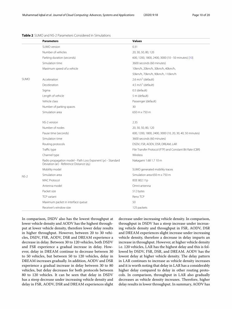
Table 2 SUMO and NS-2 Parameters Considered in Simulations
Parameters Values
SUMO
SUMO version 0.31
Number of vehicles 20, 30, 50, 80, 120
Parking duration (seconds) 600, 1200, 1800, 2400, 3000 (10 - 50 minutes) [10]
Simulation time 3600 seconds (60 minutes)
Maximum speed of a vehicle 10km/h, 20km/h, 30km/h, 40km/h,
50km/h, 70km/h, 90km/h, 110km/h
Acceleration 2.6 m/s2 (default)
Deceleration 4.5 m/s2 (default)
Sigma 0.5 (default)
Length of vehicle 5 m (default)
Vehicle class Passenger (default)
Number of parking spaces 30
Simulation area 650 m x 750 m
NS-2
NS-2 version 2.35
Number of nodes 20, 30, 50, 80, 120
Pause time (seconds) 600, 1200, 1800, 2400, 3000 (10, 20, 30, 40, 50 minutes)
Simulation time 3600 seconds (60 minutes)
Routing protocols DSDV, FSR, AODV, DSR, DREAM, LAR
Traffic type File Transfer Protocol (FTP) and Constant Bit Rate (CBR)
Channel type Wireless
Radio propagation model - Path Loss Exponent (γ ) - StandardDeviation (σ ) - Reference Distance (d0)
Nakagami 1.68 1.7 10 m
Mobility model SUMO generated mobility traces
Simulation area Simulation area 650 m x 750 m
MAC Protocol IEEE 802.11p
Antenna model Omni-antenna
Packet size 512 bytes
TCP variant Reno TCP
Maximum packet in interface queue 50
Receiver’s window size 125 packets
In comparison, DSDV also has the lowest throughput atlower vehicle density and AODV has the highest through-put at lower vehicle density, therefore lower delay resultsin higher throughput. However, between 20 to 30 vehi-cles, DSDV, FSR, AODV, DSR and DREAM experience adecrease in delay. Between 30 to 120 vehicles, both DSDVand FSR experience a gradual increase in delay. How-ever, delay in DREAM continue to decrease between 30to 50 vehicles, but between 50 to 120 vehicles, delay inDREAM increases gradually. In addition, AODV and DSRexperience a gradual increase in delay between 30 to 80vehicles, but delay decreases for both protocols between80 to 120 vehicles. It can be seen that delay in DSDVhas a steep decrease under increasing vehicle density anddelay in FSR, AODV, DSR and DREAM experiences slight
decrease under increasing vehicle density. In comparison,throughput in DSDV has a steep increase under increas-ing vehicle density and throughput in FSR, AODV, DSRand DREAM experiences slight increase under increasingvehicle density, therefore a decrease in delay imparts anincrease in throughput. However, at higher vehicle densityi.e. 120 vehicles, LAR has the highest delay and this is fol-lowed by DSDV, FSR, DSR, and DREAM. AODV has thelowest delay at higher vehicle density. The delay patternin LAR continues to increase as vehicle density increasesand it is worth noting that delay in LAR has a considerablyhigher delay compared to delay in other routing proto-cols. In comparison, throughput in LAR also graduallydecreases as vehicle density increases. Therefore, higherdelay results in lower throughput. In summary, AODV has

Muhammad Iqbal et al. Journal of Cloud Computing: Advances, Systems and Applications (2020) 9:18 Page 11 of 20
Fig. 5 Average throughput, end-to-end delay and PDR performance under increasing vehicle density. a Average throughput performancecomparison. b Average delay performance comparison. c PDR performance comparison
Muhammad Iqbal et al. Journal of Cloud Computing: Advances, Systems and Applications (2020) 9:18 Page 12 of 20
the lowest delay followed by DREAM, DSR, FSR, DSDVand LAR under increasing vehicle density.The given results shown in Fig. 5a and b are also sup-
ported by the results in Fig. 5c that shows the PDR ofTCP under increasing vehicle density. The figure showsthat similar pattern of increasing PDR as vehicle densityincreases for all routing protocols except for PDR in LARthat gradually decreases as vehicle density increases. Atlower vehicle density, AODV has the highest PDR andthis is followed by DSR, FSR, LAR and DREAM. DSDVhas the lowest PDR. In comparison, DSDV has the low-est throughput and highest delay while AODV has thehighest throughput and lowest delay at lower vehicle den-sity. Therefore, lower PDR results in lower throughput andhigher delay. Similar patterns of steep increase in PDR isobserved in DSDV and slight increase in PDR for otherrouting protocols under increasing vehicle density, hencean increase in PDR imparts an increase in throughput anda decrease in delay. However, at higher vehicle density,AODV has the highest PDR and this is followed by DSR,FSR, DREAM, and DSDV. LAR has the lowest PDR athigher vehicle density. In summary, AODV has the high-est PDR followed by DSR, FSR, DREAM, DSDV and LARunder increasing vehicle density.Initially, between 20 to 30 vehicles, all routing protocols
except LAR experiences an increase in both throughputand PDR as well a decrease in delay because increasingvehicle density attributes to increasing number of neigh-boring nodes to form paths in order to forward packets.As a result, this increases the availability and probabilityof alternative paths to route packets, thereby decreas-ing the probability of forwarding packets via congestedpaths. In addition, DSDV experiences a steep increasein throughput because at lower vehicle density, DSDVdoes not require much network resources to maintainits routing table as the routing entries are lower due tolesser number of neighboring nodes. This results in verylow routing overhead, thus exponentially increases thenumber of successful routing at a much lower delay.However, beyond 30 vehicles, all routing protocols
except LAR experiences a gradual decrease in boththroughput and PDR with an increase in delay. In thecase of DSDV and FSR, both being proactive routingprotocols are significantly affected at higher vehicle den-sity because there is an exponential increase in vehiclesto maintain their routing tables i.e. high channel occu-pancy, which overtime consume a lot of network resourcesthereby causing higher routing overhead and slower deliv-ery of packets between neighboring nodes. However, FSRstill has higher throughput compared to DSDV as FSRemploys its technique of assigning different time inter-vals to update its routing entries and there is no needfor triggering an untimely update to the routing table. Inthe case of AODV and DSR, both being reactive routing
protocols, at higher vehicle density, there is a frequentincrease in route discovery operations to establish routingwith newer neighboring nodes, thus imparting a higherrouting overhead. Similarly, DREAM floods the networkfrequently as there are more vehicles in the network, i.e.increasing routing updates as vehicles pass one another,imparting a higher routing overhead. This deduction isalso adopted for LAR, where increasing vehicle densitycause throughput and PDR to gradually decrease leadingto a gradual increase in delay as more vehicles impartfrequent routing updates. However, delay in LAR is con-siderably higher than DREAM due to more vehicles areconsidered when forwarding request message to its des-tination node, thereby imparting a higher probability offrequent request messages. Between 80 to 120 vehicles,both AODV and DSR attain a slight increase in through-put and PDR because considering the locations of neigh-boring nodes, where these nodes might be located in anarea that is not within the radius of the transmission rangeof the source node. Concurrently, the source node is alsonot located within the radius of the transmission rangeof the neighboring nodes. Thus, these results in a reduc-tion in the total RTS/CTS packets present in the wirelesschannel as the source node do not need to communi-cate with the neighboring nodes. Hence, the source nodedoes not need to initiate frequent random backoff, result-ing in lower delay, higher transmission rate and increasedthroughput.
Influence of Varying Parking Duration on TCP PerformanceFigure 6a delineates how parking duration of vehicles caninfluence TCP performance. It is assumed that there are30 UDP (background) and 30 TCP (foreground) flows,while the total number of vehicles is 50 and vehiclespeed is 50 km/h. Figure 6a shows the average through-put of TCP under varying average parking durations. Itcan be observed that in shorter parking durations i.e.between 10 to 30 minutes, throughput in both DSDV andFSR increases. However, in longer parking durations i.e.between 30 to 50 minutes, throughput in DSDV decreaseswhile throughput in FSR continues to increase. Identicalpattern of increase in throughput is seen in both AODVand DSR. However, throughput in both DREAM and LARdecreases under increasing parking durations. It is alsoworth noting that DREAM has the highest throughput inboth shorter parking durations and longer parking dura-tions despite achieving a gradual decrease in throughputas it remains static and immobile for longer period oftime. In summary, DREAM has the highest throughputfollowed by AODV, FSR, DSR, LAR and DSDV underincreasing parking durations.Results shown in Fig. 6a is further supported by results
shown in Fig. 6b that shows the average end-to-end delayunder increasing parking durations. It can be seen that

Muhammad Iqbal et al. Journal of Cloud Computing: Advances, Systems and Applications (2020) 9:18 Page 13 of 20
Fig. 6 Average throughput, end-to-end and PDR performance under different parking durations. a Average throughput performance comparison.b Average delay performance comparison. c PDR performance comparison

Muhammad Iqbal et al. Journal of Cloud Computing: Advances, Systems and Applications (2020) 9:18 Page 14 of 20
between 10 to 30 minutes of parking, delay in bothDSDV and FSR decreases but between 30 to 50 min-utes, delay in DSDV increases while delay in FSR con-tinue to decrease. Similar pattern of decrease in delaycan be seen for both AODV and DSR under increas-ing parking durations. However, delay in both DREAMand LAR increases for longer period of parking. As acomparison, throughput in AODV and DSR increasesas delay decreases under increasing parking durationswhereby throughput in DREAM and LAR decreases asdelay increases under increasing parking durations. It isalso worth noting that DREAM has the lowest delay at 10minutes of parking but it loses to AODV where it attainsthe second lowest delay at 50 minutes of parking. In addi-tion, LAR has the highest delay under increasing parkingdurations. In summary, AODV has the lowest delay fol-lowed by DREAM, FSR, DSR, DSDV and LAR underincreasing parking durations.Figure 6c shows the PDR of TCP under increasing park-
ing durations. Between 10 to 30 minutes of parking, PDRin both DSDV and FSR increases but between 30 to 50minutes of parking, PDR in DSDV decreases and PDR inFSR continues to increase. Both AODV and DSR expe-rience a gradual increase in PDR and both DREAM andLAR experience a gradual decrease in PDR for longerperiod of parking. It is seen that both AODV and DSRbeing reactive routing protocols exhibit similar patternin terms of throughput, delay and PDR under increas-ing parking durations and alternating to the increasingpattern in throughput and PDR for both AODV andDSR, where both DREAM and LAR attain decreasingpattern in both throughput and PDR under increas-ing parking durations, thereby both DREAM and LARexhibit similar pattern in both performance metrics asgeographic routing protocols. Shorter parking durationshows that DREAM has the highest PDR but it fallsbehind AODV, DSR and FSR at longer parking dura-tions. AODV attains the highest PDR followed by DSR,FSR, DREAM, LAR and DSDV under increasing parkingdurations.Increasing pattern in both throughput and PDR along
with a decrease in delay found in the two pairs of col-lective routing protocols i.e. DSDV and FSR as proactiverouting protocols and AODV and DSR as reactive routingprotocols under increasing parking durations is becauseparked vehicles remain static and immobile for longerperiod of time leading to less change in topology formingmore successful routing paths with neighboring nodes.As a result, routing of packets becomes faster and morereliable with less congestion in the network. However,the decreasing pattern in both throughput and PDR withan increase in delay found in both DREAM and LARunder increasing parking durations is due to a geographicrouting protocol characteristic where GPS is required to
enable either DREAM or LAR to establish routing withneighboring nodes that is both effective and providing lessrouting overhead. However, GPS is not required or notenabled in parked vehicle as there is no need for the vehi-cle to move, thereby vehicle speed and vehicle mobility arenegligible. This caused both DREAM and LAR to resortto increase the frequency of flooding the network forestablishing routing, imparting higher routing overheadand congestion.It can also be observed that lower throughput, lower
PDR and higher delay is experienced by DSDV at higherparking duration is because longer parking duration trig-gers DSDV to frequently send out routing messages tomaintain its routing table which overtime consumes a lotof network resources, hence imparting higher overheadcompared to shorter parking durations.
Influence of Average Vehicle Speed on TCP PerformanceIn this performance evaluation, a total of eight differentvalues of average vehicle speed are used: 10, 20, 30, 40, 50,70, 90 and 110 km/h. In total, there are 54 simulation runsto obtained the given results for six routing protocols. Theassumption on TCP and UDP traffic is the same as theprevious performance evaluations. There are 50 vehiclesand the parking duration for each vehicle is 30 minutes.Figure 7a shows the average throughput of TCP underincreasing average vehicle speed. Initially at 10 km/h,high throughput is observed in all routing protocols withDREAM attains the highest throughput. Between 10 km/hto 20 km/h, all routing protocols experience a decrease inthroughput but throughput in AODV increases. However,beyond 20 km/h, throughput in DSDV, FSR, AODV, DSRand DREAM remain consistent regardless of increasingvehicle speed. In the case of LAR, between 10 km/h to 40km/h, throughput in LAR decreases. However, LAR expe-rience a sudden increase in throughput between 40 km/hto 50 km/h. But, beyond 50 km/h, a similar pattern is seenbetween 10 km/h to 40 km/h where throughput in LARgradually decreases. As a result, DREAM attains the high-est throughput followed by AODV, FSR, DSR, DSDV andLAR.Figure 7b shows the average end-to-end delay under
increasing average vehicle speed. Initially at 10 km/h, lowdelay is observed in all routing protocols with DREAMhaving the lowest delay. Between 10 km/h to 20 km/h, allrouting protocols experience an increase in delay but delayin AODV decreases. In comparison, all routing protocolsexcept AODV experience a decrease in throughput in thisrange of vehicle speed which results in a higher delayimparts lower throughput. However, beyond 20 km/h,similar linear pattern is seen where delay for DSDV, FSR,AODV, DSR and DREAM remain consistent regardlessof increasing vehicle speed. In the case of LAR, delayincreases between 10 km/h to 40 km/h but a sudden

Muhammad Iqbal et al. Journal of Cloud Computing: Advances, Systems and Applications (2020) 9:18 Page 15 of 20
Fig. 7 Average throughput, end-to-end delay and PDR performance under varying average speed. a Average throughput performance comparison.b Average delay performance comparison. c PDR performance comparison

Muhammad Iqbal et al. Journal of Cloud Computing: Advances, Systems and Applications (2020) 9:18 Page 16 of 20
decrease in delay is attain between 40 km/h to 50 km/h.In addition, LAR experience a similar pattern of a grad-ual increase in delay for speeds beyond 50 km/h. It canalso be seen that LAR has the highest delay compared toother routing protocols under increasing vehicle speed.As a result, DREAM attains the lowest delay followed byAODV, FSR, DSR, DSDV and LAR.Results in Fig. 7a and b are further supported by the
results shown in Fig. 7c that shows the PDR of TCP underincreasing vehicle speed. It can be seen that at 10 km/h,all routing protocols have high PDR. However, between 10km/h to 20 km/h, a decrease in PDR for all routing pro-tocols except AODV that has experience an increase inPDR. In comparison, all routing protocols except AODVexperience a decrease in throughput as delay increasesunder increasing vehicle density, thereby a decrease inPDR imparts lower throughput and higher delay. How-ever, beyond 20 km/h, similar linear pattern is seen wherePDR for DSDV, FSR, AODV, DSR and DREAM remainconsistent regardless of increasing vehicle speed. In thecase of LAR, PDR decreases between 10 km/h to 40 km/hbut a sudden increase in PDR is attain between 40 km/hto 50 km/h. In addition, LAR experience a similar pat-tern of a gradual decrease in PDR for speeds beyond 50km/h. Taking into account of throughput, delay and PDRin LAR, it can be deduced that beyond the upper limitof 110 km/h, LAR would experience a continuous grad-ual decrease in both throughput and PDR with a gradualincrease in delay. In addition, it can also be seen that LARhas the lowest PDR compared to other routing protocolsunder increasing vehicle speed. Moreover, DREAM fallsbehind AODV for attaining the highest PDR and ties withDSR. As a result, AODV attains the highest PDR followedby DREAM, DSR, FSR, DSDV and LAR.Observation shown that as vehicle speed increases from
10 km/h to 20 km/h, DSDV, FSR, DSR and DREAM havea decrease in both throughput and PDR with an increasein delay. This is due to increasing vehicle mobility causinghigher topology changes and frequent disconnection withneighboring nodes, resulting in nodes falling out of theirrouting range. Similar pattern is seen in LAR as speedincreases from 10 km/h to 40 km/h, thereby same assump-tion can be said for decreasing throughput, decreasingPDR and increasing delay in LAR. However, between 10km/h to 20 km/h, only AODV has an increase in boththroughput and PDR with a decrease in delay. This phe-nomenon is due to at lower vehicle speed, there is lesserto none breaks in links between nodes and their neighborsthat have establish routing using AODV because there islesser to zero route error messages that are forwarded tothe source node, thereby there is less chance to trigger newroute discovery operations.Increasing speed between 20 km/h to 110 km/h shows
that all routing protocols except LAR exhibit linear and
consistent throughput, PDR and delay. Between 40 km/hto 50 km/h, LAR experiences a sudden increase in boththroughput and PDR along having a sudden decrease indelay. This may be due to the range of vehicle speedsis optimal for LAR to yield a small expected zone todetermine the best possible position of destination node.Smaller expected zone equates to LAR providing fewerrequest message to find its destination node as thereis reduction in region size to consider leading to lesserneighboring nodes to obtain their route reply messages.However, beyond 50 km/h i.e. between 50 km/h to 110km/h, LAR experience a decrease in both throughput andPDR with an increase in delay. This phenomenon canbe due to higher vehicle speed yielding larger expectedzone thus LAR has to provide higher frequency of routerequest messages to find its destination node, resultingin consider a larger region size with considerably highernumber of neighboring nodes to obtain their route replymessages. In addition, higher vehicle speed imparts highlydynamic topology, therefore causing LAR nodes to havefrequent disconnections between one another. Table 3below shows the summary of results obtained in terms ofaverage throughput, end-to-end delay and PDR.
DiscussionOur current work nonetheless opens up several avenuesfor future research in routing performance in the Vehic-ular Fog Computing (VFC) research domain, specificallyin increasing throughput and decreasing the delay. Thiswould include selective hopping, fog node selection fortask processing and storage, and reduction of route dis-covery and maintenance-related overhead as discussedfurther below:
• Selective hops for packets forwarding in a VFC:While the increase in vehicle density would reducethe physical distance and communication delaybetween nodes in a VFC infrastructures, data needsto be traversed in multiple hops from the source todestination that may concurrently increase the energyconsumption. Looking at the issue from anotherperspective, not all nodes need to participate in thecommunication process. Through a selective process,only several nodes are chosen to provide with theoptimal route for processing. As some vehicles staylonger than others, they would have higheravailability. Thus, this can be used as an attribute forthe selection. For instance, a low vehicle densityscenario would only have one option consisting offive hops to send data from a source to destination. Ina typical high vehicle density scenario without anyselective process, the same process would take morehops to achieve the same goal. However, using aselective process in the high vehicle density scenario

Muhammad Iqbal et al. Journal of Cloud Computing: Advances, Systems and Applications (2020) 9:18 Page 17 of 20
can provide several options to choose from thatwould give equal or even less number of hops fromthat of the former scenario. Hence, finding theoptimal route from the selective hopping can help inreducing the delay and simultaneously increasing thethroughput in the case of high vehicle density.Additionally, a vehicle mobility predictioninformation based on historical and context data ofthe vehicle can be taken into account while decidingon the hops in a packet forwarding path between asource and destination node.
• Selective vehicle for computation and storage in aVFC: Allocating a task to a fog node (vehicle) that ismobile might cause the task to be migrated as the fognode becomes unavailable. This is undesirable as themigration could produce additional overhead tocomplete a task, including moving task to a new fognode and reestablishing TCP sessions. If finding theoptimal route is not a concern, another alternative toreduce the delay is using a selective fog node process.Assuming that an intermediate (e.g. a broker) ispresent with the knowledge of all of the fog nodes’capability, this can be used to assist in the fogselection process. The intermediate can filter out thefog nodes that do not meet the requirements toprocess the task and only the ones that are eligible are
considered to process the task. The higher capabilityfog node will have a greater chance to complete thetask and hence reducing the delay (and increase TCPthroughput).
• Route discovery and maintenance-relatedoverhead reduction: Routing table needs to beupdated to give the latest and accurate information.However, frequent updates could incur overheadsand increase delay. Another possible approach toreduce such overhead could be introducing adynamic interval of routing table update. At differenttime of the day, parking duration will vary. Thelonger a vehicle stays, the less likely its routing tableneeds to be updated. To illustrate, let us considerpeak hours and off-peak hours scenarios. Duringpeak hours, vehicles are bound to have shorterparking duration. The movement implies frequentupdates in the routing table. On the other hand,vehicles tend to remain inactive for a long period oftime in the off-peak hour scenario. Thus, it isunnecessary to update the routing table frequentlyand a longer interval of update would suffice.Therefore, the update interval can be changeddynamically (short interval for peak hours and longinterval for off-peak hours) depending on thesituation in order to reduce the overhead and delay.
Table 3 Summary of results under various vehicle density, parking duration and vehicle speed
Throughput Delay PDR
Vehicle Density
Increasing vehicle density caused lower throughput, lower PDR and higher delay
LAR is highly influenced by increasing vehicle density
Highest throughput: AODV Lowest delay: AODV Highest PDR: AODV
Lowest throughput: LAR Highest delay: LAR Lowest PDR: LAR
Parking Duration
Increasing parking duration caused higher throughput, higher PDR and lower delay but DREAM
and LAR (geographic routing protocols) attain lower throughput, lower PDR and higher delay
AODV and DSR are highly influenced by increasing parking durations
Highest throughput:DREAM
Lowest delay: AODV Highest PDR: AODV
Lowest throughput: DSDV Highest delay: LAR Lowest PDR: DSDV
Vehicle Speed
Increasing vehicle speed caused lower throughput, lower PDR and higher delay
LAR is highly influenced by increasing vehicle speed
Highest throughput:DREAM
Lowest delay: DREAM Highest PDR: AODV
Lowest throughput: LAR Highest delay: LAR Lowest PDR: LAR

Muhammad Iqbal et al. Journal of Cloud Computing: Advances, Systems and Applications (2020) 9:18 Page 18 of 20
• Mechanisms required in enabling VFC inreal-world: Emerging technologies have played asignificant role in the real-world adoption of VFC, invarious levels, mainly focusing in the communicationor computation aspects. Apart from using thewell-known RSU to assist in the VFC, there existsother cost-effective intermediaries such as aFog-based broker. With virtualization, vehicleresources can be pooled and centrally managed bythe broker. The broker can obtain incoming tasksfrom the end users and schedule the tasks to thequalified vehicles that meet the task requirement forfurther processing. Furthermore, such broker wouldhave trust evaluation capabilities that are essential inthe VFC due to the dynamic and heterogeneousenvironment. Depending on the context, the trustevaluation can be derived from suitable metrics suchas security, recommendation, feedback [35], forparked vehicles, or using velocity, speed and directionfor mobile vehicles [45].
ConclusionThis paper has successfully conducted performance sim-ulation and evaluation of DSDV, FSR, AODV, DSR,DREAM and LAR routing protocols under different vehi-cle density, parking durations and vehicle speed basedon SUMO mobility traces involving parked vehicles. Inthe near future parked vehicles would be part of net-work edge computing facility (by forming VFC) in orderto reduce computational and storage burden of dedicatedcomputing facilities for edge and cloud computing. There-fore, understanding which routing protocol would be themost suitable choice for delivering traffic among the VFCnodes (vehicles) is increasingly important. This paperconcludes that AODV outperforms the other routing pro-tocols, with DREAM attaining the second-best perfor-mance in all performance metrics: throughput, averageend-to-end delay and PDR. Thereby, our study nomi-nates the use of AODV or DREAM to route packets inurban street environment. Another important findings wediscovered from the simulation results is that, in mostcases none of the routing protocols may ensure end-to-end delay less than 40 ms. Therefore, we may surmisethat VFC with IEEE 802.11p interface is not suitable forthe applications that have stringent latency requirement(e.g. 10 ms).Furthermore, although VFC enables allocation and pro-
cessing of tasks generated from the end users, there arestill other areas of concern that need future works. Theseinclude the residual battery power of vehicles and thepower needed to compute the tasks, while considering thepower needed for the vehicle to commute to its next desti-nation. Additionally, vehicle availability should be a decid-ing factor before a task can be allocated to the vehicles. In
VFC, availability can be observed from the vehicle park-ing duration and vehicle processing capabilities. These arecrucial as they will have an impact on the VFC perfor-mance in terms of the task completion time, as well asthe overall task migration that would impose additionalcommunication and processing overheads. Subsequently,this all in turn would deteriorate TCP performance assuch migration would increase occupancy of channel andthe number of times a node (a vehicle in a VFC) needs toback-off due to collision resolution.
AbbreviationsAIFS: Arbitrary inter-frame spacing; CCH: Control channel ; CSMA/CA: Carriersense multiple access/ collision avoidance; DCF: Distributed coordinationfunction; DIFS: Distributed inter-frame space; DREAM: Distance routing effectalgorithm for mobility; DSDV: Destination sequence destination vector; DSR:Dynamic source routing; EDCA: Enhanced distributed channel access; FSR:Fisheye state routing; ITS: Intelligent transportation systems; LAR: Locationaided routing; MANET: Mobile ad hoc networking; OBU: On-board units; OSM:Open street map; PDR: Packet delivery ratio; RREP: Route reply; RREQ: Routerequest; RSU: Road side units; RTS/CTS: Request to send/clear to send; RWP:Random waypoint; SCH: Service channel; V2R: Vehicle to RSU; V2V: Vehicle tovehicle; VFC: Vehicular fog computing; WAVE: Wireless access vehicularenvironment; WSMP: WAVE-mode short message protocol
AcknowledgementsThis work was supported by the National Research Foundation of Korea (NRF)grant funded by the Korean Government (MSIT) (2018R1A2B2003774).
Authors’ contributionsAll the authors contributed in this research. The order of authors in thismanuscript is maintained depending on the level of contributions they madein this research. The author(s) read and approved the final manuscript.
FundingThis research has been partially funded by National Research Foundation ofKorea (NRF).
Availability of data andmaterialsNot applicable.
Competing interestsThe authors declare that they have no competing interests.
Author details1School of Computing and Informatics, Universiti Teknologi Brunei (UTB),Tungku Highway, Gadong BE1410, Bandar Seri Begawan, Brunei Darussalam.2KAIST Institute for Information Technology Convergence, 291 Daehak-ro,Yuseong-gu, Daejeon 34141, South Korea. 3Department of Computer Science,Faculty of Engineering and Technology, Liverpool John Moores University,James Parsons Building Byrom Street, Liverpool L3 3AF, UK. 4Department ofCyber Security, Duksung Women’s University, 01369 Seoul, South Korea.
Received: 29 July 2019 Accepted: 7 February 2020
References1. Abdelgadir M, Saeed RA, Babiker A (2017) Mobility routing model for
vehicular ad-hoc networks (VANETS), smart city scenarios. Veh Commun9:154–161
2. Ali TE, al Dulaimi LAK, Majeed YE (2012) Review and performancecomparison of vanet protocols: Aodv, dsr, olsr, dymo, dsdv & zrp. In: 2016Al-Sadeq International Conference on Multidisciplinary in IT andCommunication Science and Applications (AIC-MITCSA). IEEE. pp 1–6.2016@articlepaul2012vanet, title=Vanet routing protocols: Pros and cons,author=Paul, Bijan and Ibrahim, Md and Bikas, Md and Naser, Abu,journal=arXiv preprint arXiv:1204.1201

Muhammad Iqbal et al. Journal of Cloud Computing: Advances, Systems and Applications (2020) 9:18 Page 19 of 20
3. Bates J, Leibling D (2012) Spaced out. perspectives on parking policy4. Bazzi A, Cecchini G, Menarini M, Masini B. M, Zanella A (2019) Survey and
Perspectives of Vehicular Wi-Fi versus Sidelink Cellular-V2X in the 5G Era.Futur Internet 11(6):122. https://www.mdpi.com/1999-5903/11/6/122#.https://doi.org/10.3390/fi11060122
5. Bazzi A, Masini BM, Zanella A, Thibault I (2017) On the performance ofieee 802.11 p and lte-v2v for the cooperative awareness of connectedvehicles. IEEE Trans Veh Technol 66(11):10419–10432
6. Behravesh E, Butler A (2016) Evaluation of the ieee 802.11 p multi-channeloperation in vehicular networks. PeerJ Preprints:1–8. https://doi.org/10.7287/peerj.preprints.2633v1
7. Bilstrup K, Uhlemann E, Strom EG, Bilstrup U (2008) Evaluation of the ieee802.11 p mac method for vehicle-to-vehicle communication. In: IEEE 68thVehicular Technology Conference, 2008. pp 1–5. https://doi.org/10.1109/vetecf.2008.446
8. Bonomi F, Milito R, Zhu J, Addepalli S (2012) Fog computing and its role inthe internet of things. In: Proceedings of the first edition of the MCCworkshop on Mobile cloud computing. ACM. pp 13–16. https://doi.org/10.1145/2342509.2342513
9. Byers CC (2017) Architectural imperatives for fog computing: Use cases,requirements, and architectural techniques for fog-enabled iot networks.IEEE Commun Mag 55(8):14–20
10. Cao J (2016) Effects of parking on urban traffic performance. PhD thesis.ETH Zurich, Zurich
11. Cogill R, Gallay O, Griggs W, Lee C, Nabi Z, Ordonez R, Rufli M, Shorten R,Tchrakian T, Verago R, et al. (2014) Parked cars as a service deliveryplatform. In: Connected Vehicles and Expo (ICCVE) 2014 InternationalConference on. IEEE. pp 138–143. https://doi.org/10.1109/iccve.2014.7297530
12. Commission E (2013) Evaluation Study on Speed Limitation Devices.Technical report
13. Cunha F, Villas L, Boukerche A, Maia G, Viana A, Mini RA, Loureiro AA(2016) Data communication in vanets: Protocols, applications andchallenges. Ad Hoc Netw 44:90–103
14. Dahiya A, Noonia A, Banta Singh Jangra J (2010) Vehicular ad hocnetworks (vanets): Simulation and simulators. Int J Res Manag Sci Technol2(1):51–56
15. Deshmukh RS, Chouhan TS, Vetrivelan P (2015) Vanets model: Vehicle-to-vehicle, infrastructure-to-infrastructure and vehicle-to-infrastructurecommunication using ns-3. Int J Curr Eng Technol 5:2053–2057
16. Fida N, Khan F, Jan MA, Khan Z (2016) Performance analysis of vehicularadhoc network using different highway traffic scenarios in cloudcomputing. In: International Conference on Future Intelligent VehicularTechnologies. Springer. pp 157–166. https://doi.org/10.1007/978-3-319-51207-5_15
17. Filippi A, Moerman K, Daalderop G, Alexander PD, Schober F, Pfliegl W(2016) Ready to roll: Why 802.11 p beats lte and 5g for v2x. NXP SemicondCohda Wirel Siemens White Paper. https://assets.new.siemens.com/siemens/assets/public.1510309207.ab5935c545ee430a94910921b8ec75f3c17bab6c.its-g5-ready-to-roll-en.pdf
18. Garg N, Aswal K, Dobhal DC (2012) A review of routing protocols inmobile ad hoc networks. Int J Inf Technol 5(1):177–180
19. Hou X, Li Y, Chen M, Wu D, Jin D, Chen S (2016) Vehicular fog computing:A viewpoint of vehicles as the infrastructures. IEEE Trans Veh Technol65(6):3860–3873
20. Houssaini ZS, Zaimi I, Oumsis M, Ouatik SEA (2017) Comparative study ofrouting protocols performance for vehicular ad-hoc networks. Int J ApplEng Res 12(13):3867–3878
21. Hussain R, Son J, Eun H, Kim S, Oh H (2012) Rethinking vehicularcommunications: Merging vanet with cloud computing. In: 4th IEEEInternational Conference on Cloud Computing Technology and ScienceProceedings. IEEE. pp 606–609. https://doi.org/10.1109/cloudcom.2012.6427481
22. Jaiswal K, Prakash O (2014) An analysis of vanet topology based routingapproach on various parameters. Int J Comput Sci Inf Technol5(4):4975–4980
23. Khairnar VD, Pradhan DS (2014) Simulation based: Study and analysis ofrouting protocol in vehicular ad-hoc network environment. arXivpreprint. arXiv:1403.6013
24. Ko Y-B, Vaidya NH (2000) Location-aided routing (lar) in mobile ad hocnetworks. Wirel Netw 6(4):307–321
25. Letirand F, Delhomme P (2005) Speed behaviour as a choice betweenobserving and exceeding the speed limit. Transp Res Part F: TrafficPsychol Behav 8(6):481–492
26. Li F, Wang Y (2007) Routing in vehicular ad hoc networks: A survey. IEEEVeh Technol Mag 2(2):12–22
27. Li YJ (2010) An overview of the dsrc/wave technology. In: InternationalConference on Heterogeneous Networking for Quality, Reliability,Security and Robustness. Springer. pp 544–558. https://doi.org/10.1007/978-3-642-29222-4_38
28. Moravejosharieh A, Modares H, Salleh R, Mostajeran E (2013) Performanceanalysis of aodv, aomdv, dsr, dsdv routing protocols in vehicular ad hocnetwork. Res J Recent Sci ISS 2277:2502
29. Nagaraj U, Kharat DM, Dhamal P (2011) Study of various routing protocolsin vanet. Int J Comput Sci Technol (IJCST) 2(4):45–52
30. Newaz SHS, Cuevas ÁLee GM, Crespi N, Choi JK (2013) Adaptivedelay-aware energy efficient TDM-PON. Comput Netw 57(7):1577–1596
31. Omar HA, Lu N, Zhuang W (2016) Wireless access technologies forvehicular network safety applications. IEEE Netw 30(4):22–26
32. Omar HA, Zhuang W, Li L (2012) Vemac: A tdma-based mac protocol forreliable broadcast in vanets. IEEE Trans Mob Comput 12(9):1724–1736
33. Pallis G, Katsaros D, Dikaiakos MD, Loulloudes N, Tassiulas L (2009) On thestructure and evolution of vehicular networks. In: Modeling, Analysis &Simulation of Computer and Telecommunication Systems, 2009.MASCOTS’09. IEEE International Symposium on. IEEE. pp 1–10. https://doi.org/10.1109/mascot.2009.5366230
34. Paul B, Ibrahim M, Bikas M, Naser A (2012) Vanet routing protocols: Prosand cons. arXiv preprint arXiv:1204.1201
35. Rahman FH, Au TW, Newaz SH, Suhaili WS, Lee GM (2018) Find mytrustworthy fogs: A fuzzy-based trust evaluation framework. Futur GenerComput Syst. https://doi.org/10.1016/j.future.2018.05.061
36. Reis AB, Sargento S, Tonguz OK (2017) Parked cars are excellent roadsideunits. IEEE Trans Intell Transp Syst 18(9):2490–2502
37. Nadas ZRTS, Racz S (2016) Per packet value: A practical concept fornetwork resource sharing. In: 2016 IEEE Global CommunicationsConference (GLOBECOM). IEEE. pp 1–7. https://doi.org/10.1109/glocom.2016.7842125
38. Safi QGK, Luo S, Pan L, Liu W, Hussain R, Bouk SH (2018) Svps: Cloud-basedsmart vehicle parking system over ubiquitous vanets. Comput Netw138:18–30
39. Safi QGK, Luo S, Wei C, Pan L, Yan G (2018) Cloud-based security andprivacy-aware information dissemination over ubiquitous vanets.Comput Stand Interfaces 56:107–115
40. Saha D, Wararkar P, Patil S (2019) Comprehensive study and overview ofvehicular ad-hoc networks (vanets) in current scenario with respect torealistic vehicular environment. Int J Comput Appl 975:8887
41. Salahuddin MA, Al-Fuqaha A, Guizani M (2016) Reinforcement learningfor resource provisioning in the vehicular cloud. IEEE Wirel Commun23(4):128–135
42. Sani AMIPH, Newaz SS, Wani SMA, Wan AT, Jahan S, et al. (2017) Tcpperformance evaluation under manet routing protocols in disasterrecovery scenario. In: Advances in Electrical Engineering (ICAEE) 2017 4thInternational Conference on. IEEE. pp 389–394. https://doi.org/10.1109/icaee.2017.8255387
43. Shah MM, Serasia S, Patel H (2015) Simulation-based performanceevaluation of routing protocols for parking. Int J Comput Sci MobComput 4(4):335–340
44. Simsek M, Aijaz A, Dohler M, Sachs J, Fettweis G (2016) 5g-enabled tactileinternet. IEEE J Sel Areas Commun 34(3):460–473
45. Soleymani SA, Abdullah AH, Zareei M, Anisi MH, Rosales-Vargas C, KhanMK, Goudarzi S (2017) A Secure Trust Model Based on Fuzzy Logic inVehicular Ad Hoc Networks With Fog Computing. IEEE Access5:15619–15629
46. Taleb AA (2018) Vanet routing protocols and architectures: An overview.JCS 14(3):423–434
47. Tyson G, Sastry N, Cuevas R, Rimac I, Mauthe A (2013) A survey of mobilityin information-centric networks. Commun ACM 56(12):90–98
48. Vats S, Kumar S, Shukla S, Shankar S (2017) Vanet: A future technology. IntJ Sci Res Publ 7(2):2017
49. Wang S-Y, Chao H-L, Liu K-C, He T-W, Lin C-C, Chou C-L (2008) Evaluatingand improving the tcp/udp performances of ieee 802.11 (p)/1609networks. In: Computers and Communications, 2008. ISCC 2008. IEEE

Muhammad Iqbal et al. Journal of Cloud Computing: Advances, Systems and Applications (2020) 9:18 Page 20 of 20
Symposium on. IEEE. pp 163–168. https://doi.org/10.1109/iscc.2008.4625624
50. World Health Organization (2015) Global Status Report on Road Safety2015. Technical report
Publisher’s NoteSpringer Nature remains neutral with regard to jurisdictional claims inpublished maps and institutional affiliations.