research strategy for modeling the complexities of turbine ...€¦ · research strategy for...
TRANSCRIPT

NASA Technical Memorandum 107161
//j-..,_y
Research Strategy for Modeling the
Complexities of TurbineHeat Transfer
Robert J. Simoneau
Lewis Research Center
Cleveland, Ohio
Prepared for the
International Conference on Turbulent Heat Transfer
sponsored by the Engineering Foundation
San Diego, California, March 10-15, 1996
@• _7/_ _"
National Aeronautics and
Space Administration
https://ntrs.nasa.gov/search.jsp?R=19960015901 2020-05-02T07:45:02+00:00Z

RESEARCH STRATEGY FOR MODELING THECOMPLEXITIES OF TURBINE HEAT TRANSFER
by
Robert J. Simoneau 1
NASA Lewis Research Center
Cleveland, OH 44135
INTRODUCTION
There is no shortage of complex heat transfer problems, so the title problem is merely one with
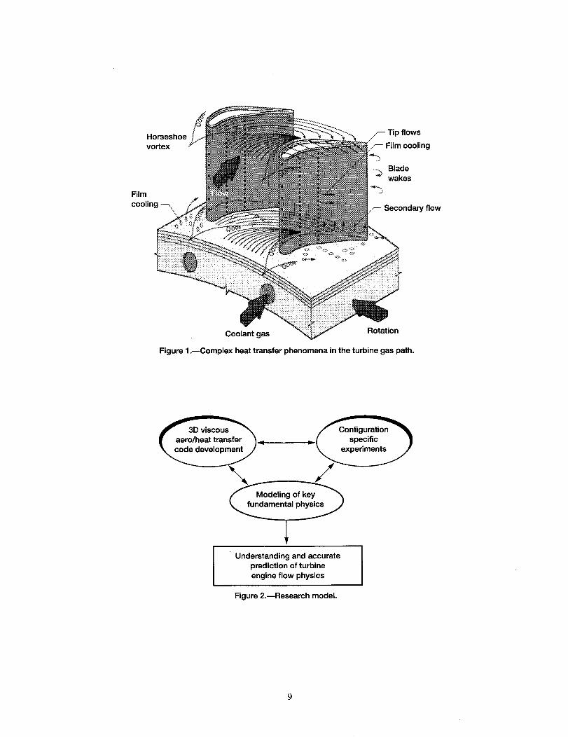
which the author is familiar and one for which we have a nice story to tell. Being more specific,the subject of this paper is a NASA research program, known as the Coolant Flow ManagementProgram, which focuses on the interaction between the internal coolant channel and the externalfilm cooling of a turbine blade and/or vane in an aircraft gas turbine engine. As can be seen in afrequently used illustration, figure 1, the turbine gas path is really a very complex flow field. Thecombination of strong pressure gradients, abrupt geometry changes and intersecting surfaces,viscous forces, rotation, and unsteady blade/vane interactions all combine to offer a formidablechallenge. To this, in the high pressure turbine, we add the necessity of film cooling.
The ultimate goal of the turbine designer is to maintain or increase the high level of turbineperformance and at the same time reduce the amount of coolant flow needed to achieve this end.Simply stated, coolant flow is a penalty on the cycle and reduces engine thermal efficiency.Accordingly, understanding the flow field and heat transfer associated with the coolant flow is apriority goal. It is important to understand both the film cooling and the internal coolant flow,particularly their interaction. Thus, the motivation for the Coolant Flow Management Program.
The paper will begin with a brief discussion of the management and research strategy, will thenproceed to discuss the current attack from the internal coolant side, and will conclude by looking atthe film cooling effort - at all times keeping sight of the primary goal the interaction between thetwo. It should be emphasized that this paper is a discussion of an approach to a problem and not acomprehensive review of the subject. Only references specifically related to the program are listedand cited. Also, since this is fairly early in a work in progress, many of the references are eitherprivate communication or papers being submitted to conferences. The reader is referred toSimoneau and Simon (1993) and Iacovides and Launder (1995) for more general discussions andreferences on external and internal turbine blade cooling.
One of the themes of this paper is that complex heat transfer problems of this nature cannot beattacked by single researchers or even groups of researchers, each working alone. It truly needsthe combined efforts of a well-coordinated team to make an impact. Despite the fact that there isonly one author, it is important to note that this is a team effort. The government players on theteam are specifically acknowledged at the end of this introduction and the industry and university
contributions are clearly identified throughout the paper.
The author wishes to acknowledge the NASA personnel, including both the civil service staff andsupport service contractors, who are the government arm of this effort and who have providedmost of the material presented herein. They include: Herbert J. Gladden, Steven A. Hippensteele,Philip E. Poinsatte, Douglas R. Thurman, James A. Heidmann, Kestutis C. Civinskas, and John
i Present Address:
Mechanical Engineering DepartmentCarnegie Mellon UniversityPittsburgh, PA 15213
R. Schwabof NASA; DavidE. Rigby andHienLai of NYMA Inc.; Vijay K. GargandAli Amefiof AYT Inc.; and Erlendur Steinthorsson of ICOMP. The contributions from our industry and
university partners will be noted, as they appear.
RESEARCH STRATEGY
The first cornerstone of the research strategy is that complex problems of this nature cannot besolved by a single approach. Nor can they be solved by multiple, but disconnected, approaches.A dataset, a computer program, a turbulence model - none by themselves can solve the problem;however, taken together in an interactive manner they can be powerfully synergistic. Thus, theresearch model for this and most major research programs at NASA Lewis is the interactivecomputational/experimental/modeling model, illustrated in figure 2. The ultimate goal is to have anaccurate and manageable computational capability. This is guided and validated by both
fundamental and configuration specific experiments. A very important ingredient, one which linksthe other two and makes the solution understandable and manageable, is the modeling of the keyfundamental physics. When all of this is worked together the potential for success is greatlyenhanced.
This model doesn't just happen, however, just because we say it is a good model. It takes thecoordinated effort of a committed team. The first ingredient to this is to get a wide range of talentand input. The Coolant Flow Management Team began the process with a tour of several of theaircraft engine manufacturers, presenting their preliminary thoughts and seeking guidance toformulating a strong and meaningful program. Earlier, Dr. Ray Gaugler of NASA Lewis surveyedthe industry regarding the advisability and recommended thrust for a restart of fdm cooling atNASA. As a result of these visits, surveys and discussions, the team made a number ofmodifications to the origin plan. Industry expressed strong support for pursuing a computationalfilm cooling capability, but cautioned that it couldn't be computationaUy overwhelming. Theyencouraged detailed studies of the internal passages for understanding and modeling, but not fordesign. They encouraged an effort to understand and couple the bleed from the internal passagesto film cooling and how it affected the heat transfer on both sides. The industry partners did morethan provide guidance. Several are performing research contracts or providing cooperative input.
As a result of all of this investigation and discussion the research planning team identifiedturbulence modeling, grid generation and validation data as the essential elements in the program.
Finally, the team looked to the university community for its expertise. Several research grantshave been put into place, including three grants that were the result of an open solicitation forinnovative university research in film cooling. The resulting government/industry/university
partnership is illustrated in figure 3. A key to success of this partnership will be strongcommunication among all of the players, not just the government team. While this exists to someextent, it is an area that is still developing. The program is relatively new. However, there areother models at NASA, such as the By-Pass Transition Program and the Multi-Stage Flow PhysicsProgram, that have successfully employed this model.
Another key feature of the strategy is planning. The research team needs to have a goodunderstanding of the research objectives and has to come to some agreement as to the best use ofthe available resources to meet that objective. One approach is to use traditional TQ techniques,such as the fishbone charts, illustrated in figure 4. Using such instruments, the team established acorporate opinion as to the elements needed in the program to lead to a high expectation of success.Also, to know where to place emphasis, and how to evaluate progress. Of course, it is necessaryto be sure that both people and money are assigned to these areas. Such charts exist, but they areconsidered a bit sensitive and are not included herein.
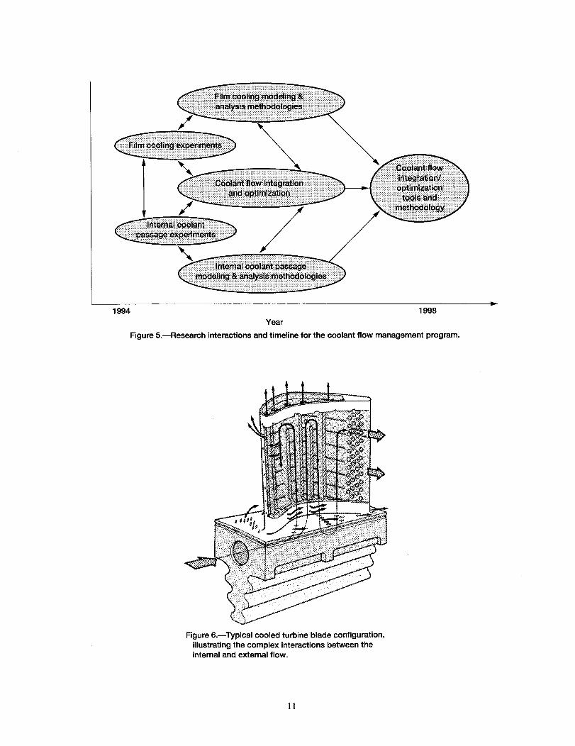
Finally, while it is not necessarilytrue of all research,an effort suchas this has to haveveryspecific goals and timelines to meet those goals. In consultationwith industry, regardingtimeliness,andafterdiscussionswithin theteam,regardingreasonablepotentialfor success,a goalof havingsignificantimprovementin currentcapabilityby 1998wasestablished.This is shown infigure5 andtheCoolantFlow ManagementTeamis workingto thatend.
COOLANTFLOWMANAGEMENT
Beforegoing into thedetailsit is probablynecessaryto definewhatwe meanby CoolantFlowManagement.Using a typical, albeit somewhatold, high pressureturbineblade cooling flowconfiguration,figure 6, one can simply statethat coolant flow managementis the technicalcapabilityto makedesigndecisionson theamountandlocationof cooling air flow, both on theinsideandtheoutsideof thebladeto achievemaximumperformanceatminimumcoolantair supplyperblade. It is thegoalof theCoolantFlow ManagementProgramto developnew technicaltoolsthatwill allow turbineheattransferdesignersto assembleadesignanalysissystemwhich they feelwill substantiallyenhancetheir ability to do this. Onewill notethatit is not agoal to provide adesignmethod. This is outsideof the expertiseandresponsibilityof the team. The goal is toprovideanintegratedsetof technicaltoolsthatallow theturbineheattransferdesignerto do that.
Thekeyfeaturesof theproblemareillustratedin figure7. Hot gaspassesover the rotating blade.A film of air, taken from the later stages of the compressor, is injected close to the surface to forma protective blanket of coolant. The success of the injected coolant flow is dependent on manyvariables: the free-stream turbulence, the upstream wakes, the rotational forces and secondaryflows, and the details of the flow out of the holes. Inside the blade the same is true, except forwakes. On the other hand a new complication is added in the form of ribs and other devices toenhance turbulence and increase heat transfer. One will note that the primary flow direction isradial, adding another complication, buoyancy and Coriollis forces. One will also note that theflow into the film coolant holes is most often at right angles to the main coolant flow direction.Finally, the sketch was deliberately drawn to show that optimum placement of holes on one sidemight not be optimum on the other. Thus coolant hole entrances could be in many positionsrelative to the protruding turbulence promoters.
It is this complex interaction between the inside and outside flow, as it enters and exits the holes,
which is the focus of the research and certainly qualifies it as a title problem for a session on HeatTransfer in Complex Flows.
INTERNAL CHANNEL SIDE OF THE PROBLEM
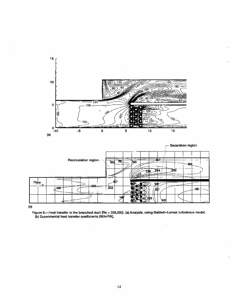
A fair amount of effort at NASA Lewis and elsewhere has already been directed to the internalcoolant channel side of the problem. The research at NASA was motivated by an attempt to predictthe flow and heat transfer in an advanced concept cooled radial turbine. The objective wassupported by both an experimental and computational attack. Today, it serves as a good beginningto the current effort. To support research an experiment was conducted in what was know as the"Branched Duct" by Russell et. al. (1993, 1996). It attempted to capture the key features of thecooled radial turbine problem, albeit without rotation. The results of this experiment provide ahighly detailed dataset and, although the configuration is no longer of primary interest, the datasetremains an excellent challenge to the task.
Accordingly, the computational community has been addressing this problem. The Coolant FlowManagement team have also used this problem to test their approach. As they approached thisproblem the team, using the thinking illustrated in the fishbone charts of figure 4, agreed upon agrid and algorithm approach to the problem. The team agreed that an emphasis on doing the best in
eachtechnicalareawould not necessarilyproducethe best integratedresult, Thus, the teamselecteda multiblock grid approachas their choicebetweenadvancedtechnologyand provencapability. Theyselectedthecommercialgrid codeGRg)PRO(1993) asmeetingthis need. Anexampleof the results,beginningwith the grid areshownin figure 8. The figure alsoillustratesthekey featuresof thebranchedductexperimentgeometry. Intuitively onewould anticipatethatthis was a goodgrid choice. It shouldbe notedthat, while the geometryis relativelysimple, itcomprehendsmostof themajor features,exceptrotation,Thekey featuresaretheflow split andthe turbulencepromotingpins. If the analysiscan capturethe flow split and the heat transferbehindthepins,it will bea significantstepforward. The teamhavealsosettledon a 3D Navier-Stokescode,theTRAF3Dcodeof Amonneet. al. (1991),asthecodetheywill use.
Computationalresults,producedby Steinthorsson,et. al. (1996) are shown in figure 9a. Theresults,compared with the experiment of Russell et. al. (1993, 1996) in figure 9b are promising.The key features are captured. One would not expect the Baldwin-Lomax model to resolve the areabehind the pins. This is an area for more work
The team has now turned their attention to geometries that are more typical of cooled axial turbines,the serpentine passages with turbulence promoting ribs. These geometries have actually received aconsiderable of study both experknentaUy and analytically and the team intends to use thoseresults. However, they are not aware of any approaches at this time which include the film coolingbleed from the coolant channels - the main focus of the integrated study.
As a first step towards that objective, the NASA CFD team are developing their multiblock gridroutines for such geometries and testing the results against experiments of Arts, et. al. (1992).Figure 10 shows a conventional single grid and a multiblock grid, as applied to the turn region ofthe Arts, et. al. duct. One can readily see how much nicer the multiblock grid wraps around thedivider and goes into the square comers. The effect for the full channel is shown in figure 11.
The research is being reported in a forthcoming paper by Rigby, et. al. (1996) They found amongother things that the multiblock grid arrangement gave at least as good, if not better results, using
only one third the grid points, figure 12. The results are compared to the Arts et. al. (1992) data infigure 13. The calculation appears to do a very good job in the upper comer and just around thedivider. It appears to miss the re-attachment point and subsequent high heat transfer. The team areencouraged by these results and are pursuing methods to improve them, particularly looking atturbulence models. Under NASA grant Stephens, et. al. (1995a, 1995b) at Carnegie MellonUniversity are studying the details of the flow physics and heat transfer in the immediate region ofthe turbulence promoting ribs, also using a multiblock grid approach. The complexity of the flowfield and heat transfer is shown in figure 14.
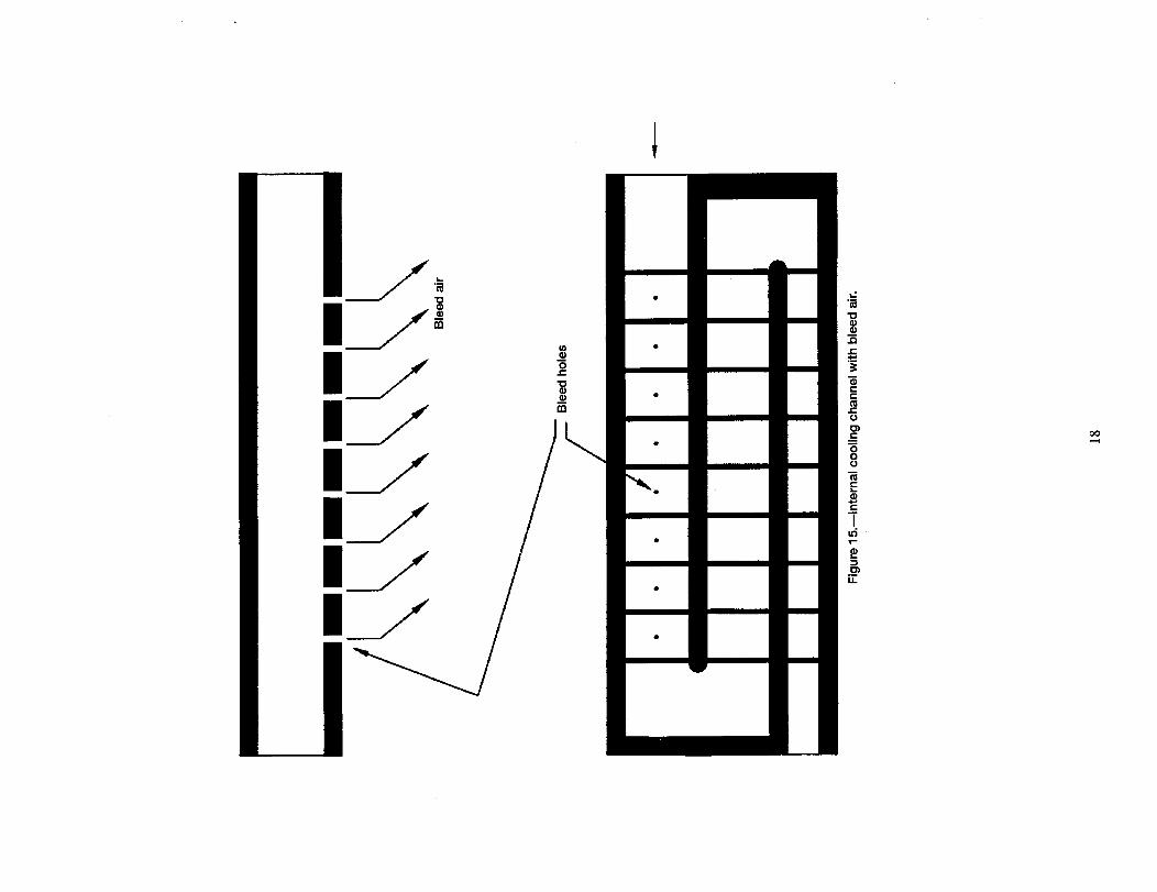
Lau, et. al. (1964) have been studying the serpentine passage geometry with turbulence ribs atNASA. The passage geometry is shown in figure 15 with liquid crystal results shown in figure16. The geometry is currently being modified, as illustrated in figure 15 to include bleed out of theinternal passages, as one would expect in a film cooled blade. The first experiments have the holesat 90 degree entrance angle. Other angles and orientations will be studied as the work progresses.
All of the above studies are at rather large scale and they are non-rotating. They are intended tohelp develop and validate the computational analyses. Their primary strength lies in the fact that alot of detail can be studied and, as the developing research calls for it, changes are easy andinexpensive to make. However, the real turbine is rotating and very high buoyancy and Coriollisforces exist in the internal passages and must be addressed. Accordingly, part of the Coolant FlowManagement program includes contracts at Pratt & Whitney/United Technologies Research Center(P&W/UTRC) (Wagner (1996)) and at Scientific Research Associates (SRA) (Tse (1996)). Bothgroups are using almost identical geometries, the very realistic one shown in figure 17. AtP&W/UTRC the focus is on heat transfer, using the transient liquid crystal method for a heatedmodel flowing air and rotating in a centrifuge. Although excellent heat transfer detail is evolving,
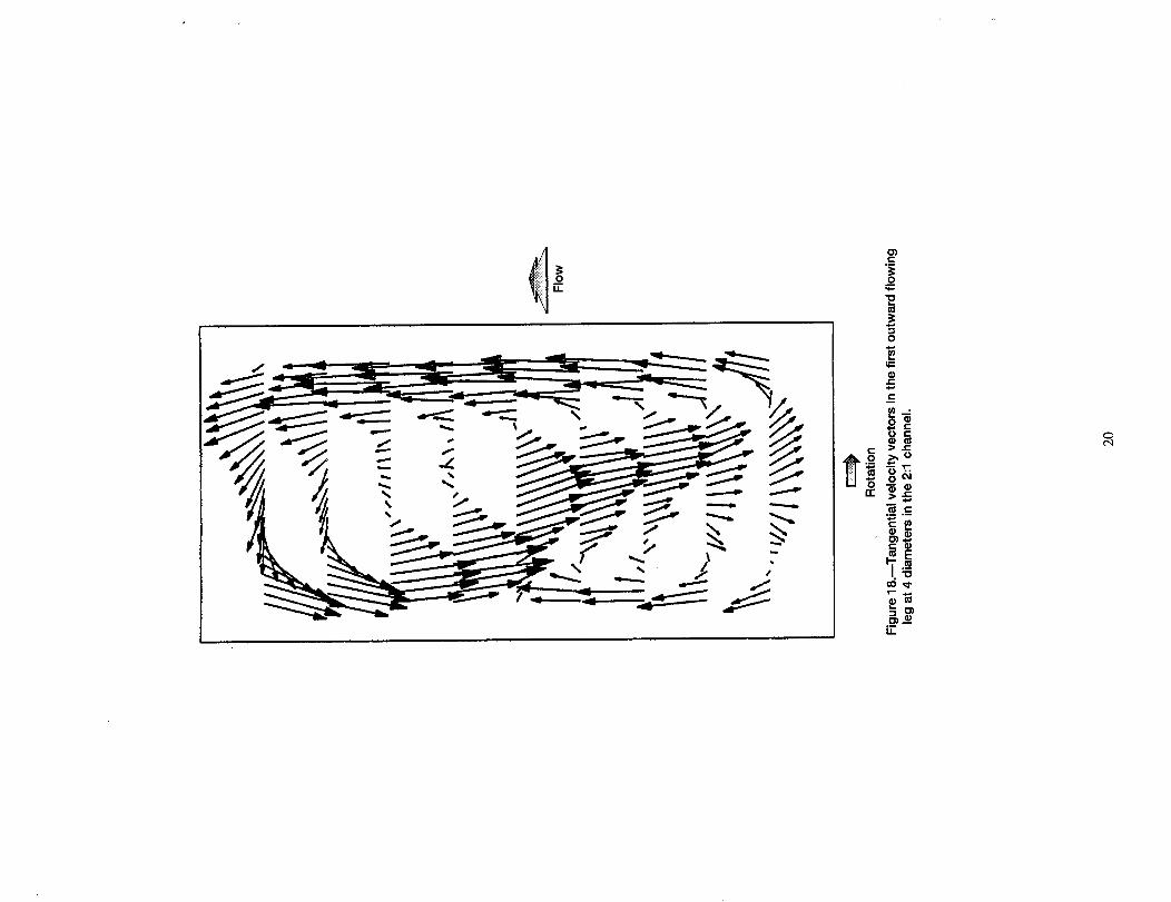
very little flow detail can be measured in this experiment. At SRA a companion rotatingexperiment is using a matched index of refraction technique and laser anemometry to get highlydetailed maps of the flow field, such as illustrated for one section at one case in figure 18. At onlyfour hydraulic diameters into the passage a counter-clockwise swirl and corner recirculation havealready setup. Especially noteworthy is the asymmetry of the flow field. By its very nature thematched index of refraction technique requires an isothermal - no buoyancy force - flow field;however, it does include Coriollis forces and provides one more piece to the puzzle.
With all of these efforts the team feels that they truly have a comprehensive and well-integratedattack on the key heat transfer and fluid physics of the internal coolant channel with film coolingbleed.
EXTERNAL FILM COOLING SIDE OF THE PROBLEM
A similar integrated attack is underway on external film cooling side with the same emphasis onunderstanding the details of the flow out of the hole and its effect on film cooling. The long termgoal is to establish a computational film cooling analysis capability that is accurate and manageable,so that intelligent decisions can be made about the heat transfer design of cooled turbine blades.
On of the fundamental studies linking the inside to the outside is being conducted under NASAgrant at the University of Minnesota by Simon (1996). The focus is on creating realistic, albeitnon-rotating, entrance flow fields to the film cooling holes. A couple of these are illustrated infigure 19. The key features are twofold. First, the holes are very short, typically 2-3 L/D, as onwould find in a turbine. The flow into the hole is at a variety of angles to the hole entrance and notnecessarily on a streamline parallel to the hole center-line, again, as one might find in the internalpassages of a turbine blade (c.f. figures 6 and 7). To begin the research Wang, et. al. (1996)studied the flow out of the holes with a fully developed (i.e. long) inlet. The results show that thetransverse eddy diffusivity can be very high relative to the normal direction and these results willneed to be incorporated into models for the film cooling hole injection region.
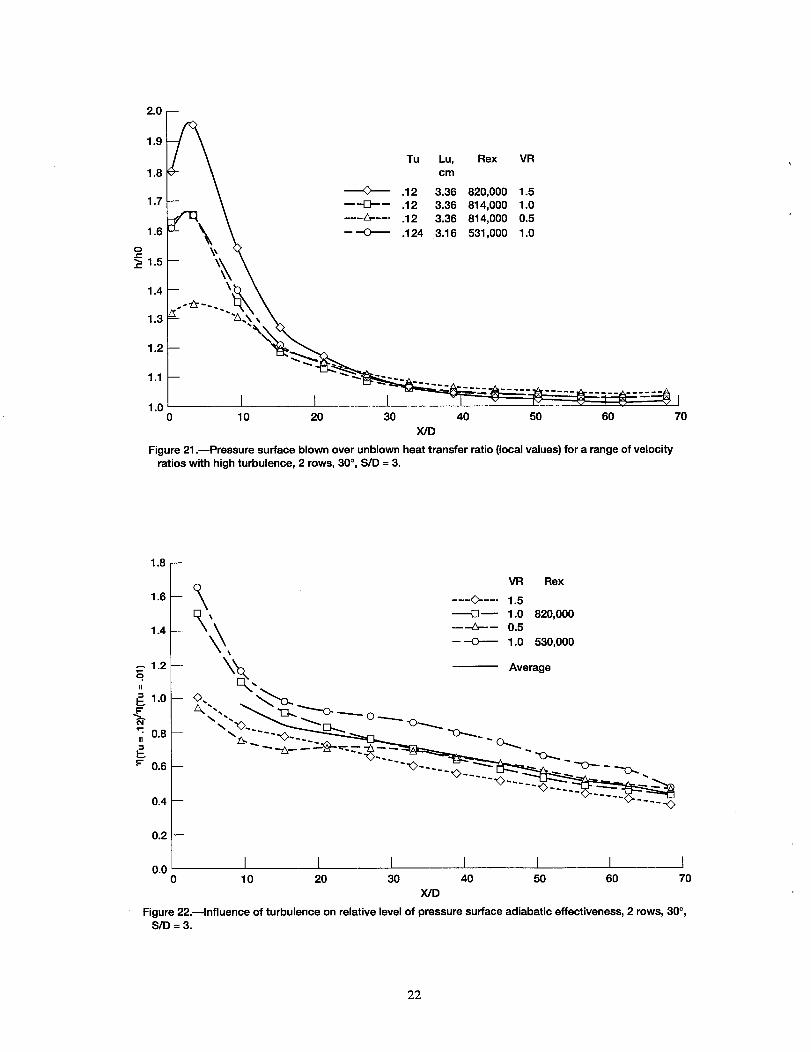
Another experiment is being conducted under NASA contract at Allison Engine Co. by Ames(1995). Using a cascade of airfoils, Ames is measuring both heat transfer and details of theturbulent flow field for flow both with and without film cooling. The results, figure 21, areshowing that near the holes on the pressure surface, when the flow is subject to high freestreamturbulence, the heat transfer with film cooling could actually be higher that without film cooling.This could be happening because a flow that would be otherwise laminar on the pressure surface isbeing disturbed by the coolant flow. It raises a question concerning the use of film cooling on the
pressure side. Another unusual result is that the adiabatic effectiveness may actually be better nearthe hole when the free stream turbulence is higher, as shown in figure 22. Over most of the flowthe trend is what one would anticipate, the free stream turbulence reduces effectiveness of the filmcoolant. The near hole effect might be explained by the turbulence spreading the coolant out faster.The CFD analyses should be able to explain these effects, if the analysis is to be successful.
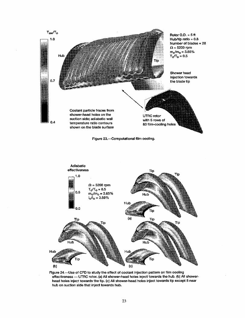
The analysis that is currently underway and is the cornerstone for much of the work is that of Garg
et. al. (1995a, 1995b, 1996), illustrated in figures 23 and 24. The analysis is a full Navier-Stokesanalysis with several types of turbulence models available. At present the film cooling, holestypical employ approximately 21 grid points. A variety of flow profiles out of the holes have beenstudied. The code is quite well developed and early comparisons with data have been promisingand have provided considerable help in guiding the overall program. One of the long term goals ofthe program is to provide computational tools that will accurately and efficiently allow one toexplore the effect of changes in geometry on fdm cooling effectiveness, such as illustrated in figure24, showing different injection patterns for the showerhead holes. At present these calculationsuse about 1-2 million grid points, requiring the memory of the Cray-90, and take about 12 hourson the Cray-90 for the initial case (5 hours for follow-up cases, such as in figure 24).
5
Furthermore,while earlycomparisonsarepromising,their accuracyasyet to be fully established.This why somuchattentionis beingpaidto theholeregion. So we canaccuratelymodel theflowandusethesemodelsto speedthecalculationandassuretheaccuracy.
Accordingly,in additionto thestudiesat theUniversityof Minnesota,thereis astudyatOhio StateUniversityunderaNASA GraduateStudentResearchFellowship(GSRP)to studyinternalcoolantplenumsand their effect on ftlm cooling effectiveness. There is a grant at Louisiana StateUniversity to developanLES databaseon theflow physicsaroundthehole, andanotherNASAGSRPat Universityof Arizonaby Quintana,et. al. (1996) to studyfilm cooling augmentationbyactiveflow control.
To supportthiscodeandmodeldevelopmentatransientliquid crystalftlm coolingcascadeis underconstructionat NASA Lewis. It is a vaneconfigurationandtherecommendeddesignfor it wassuppliedby Dr. David Winstanleyof Allied Signal. A stereolithographymodel of the vane,suppliedby Allied Signal,is shownin figure 25. Theexperimentalresearchteamconductingboththis experimentandtheinternalcoolantwith bleedexperimentwill be working closely with themodelersandthecodedevelopers,aswell as the otherexperimentalists,to get the most out oftheseexperiments,focusingon thefull integration.
Finally, just as on the coolantchannelside, the film cooling flow is really subjectto rotation.However,on theexternalsideit is theeffectof wakeson thefilm cooling, ratherthanbuoyancyandCoriollis forces,which is probablythebiggestconcern. Will the wakesseriouslydisturb thef'tlm cooling flow? A computationaland analytical study is underway a NASA Lewis byHeidmannet.al. (1996) to studywakeeffects. Theexperimentis beingconductedin an annularcascadewith a spokedwheeldisturbancegenerator,as shownis figure 26. The analysisis wellunderway and one frame from the time-resolvedcalculationis shown in figure 27. Thecomputationalresultsareshowing a rathersharpfluctuationin the heattransferin the stagnationregionnearthefilm coolinghole rows. Theresultsareexpectedearly this year. A companionexperimentis alsowell underwayatTexasA&M Universityby Hui, et. al. (1996). The TexasA&M experimentis usingliquid crystaltechniquesin a low speedlinearcascadewith anupstreamdisturbancegenerator.Theftrst testswithout film injectionareshowing, asexpected,higherheattransferin thewakes.Thework iscontinuingwith film coolinginjection. Rotor/statorinteractioncalculationsontwo different turbinestageconfigurationsarealsounderwayat WesternMichiganUniversityby Dorney(1993, 1995). Thesewill form a baselinefor futurerotor/statorinteractioncalculations,whichemphasizetheeffects onfilm cooling.
CLOSINGREMARKS
TheCoolantFlow ManagementProgramis off to a good startin putting in placethe necessaryingredientsfor successfullyattackingthis very complexheattransferprocessand arriving at aresult, which will enhanceour capability to build betterperforming, more thermally efficientturbines.
Oncethemodelsaredevelopedto expediteanalyses,anintegrationandoptimizationstrategycanbeput inplace.
Thesuccess,however,will behighlydependenton theability of all theplayersto continueto keeptheir researchfocusedon the commongoal. Good communicationwill be critical. Regularassessmentof progressis important. In anyendeavor,ascomplexasthis, someof the initial ideaswon't betherightones.A steadyandconstructivelycritical sharingof progressandideaswill bemost important. To this end the researchteam is makingplans for the first Coolant FlowManagementWorkshop,composedprimarily of thekey contributorsto the program, to be heldsometimein 1996.
Thecomplexheattransferproblemsneedstrategiesfor success. The CoolantFlow ManagementProgramis one suchstrategy. Hopefully, it can be a model. Certainly othersare possible;however,I wouldcontendthattheseproblemscannotbesolvedin isolation.
REFERENCES
Ames,F. (1995)Privatecommunicationvia monthlyprogressreports.
Arnonne, A., Liou, M.-S., and Povinelli, L. A. (1991) "Mulfigrid Calculation of ThreeDimensionalViscousCascadeFlows," AIAA PaperAIAA-91-3238.
Arts, T., Lambert,deR.,Rau,M. andActon, P. (1992)"Aero-Thermal Investigationof theFlowDevelopingin a 180DegreeTurn Channel."VKI-PreprintNo. 1992-10.
Dorney,D. J., andDavis,R. L. (1993)"NumericalSimulationof Turbine 'Hot Spot' AlleviationUsingFilm Cooling," AIAA Journal of Propulsion and Power, Vol. 9, No. 3, May-June1993, pp. 329-336.
Dorney, D. (1995) Private communication via monthly progress reoports.
Garg, V. K. (1996) "Adiabatic Efeectiveness and Heat Transfer Coefficients on a Film-Cooled
Rotating Blade," Paper to br presented at the 41st ASME International Gas Turbine andAeroengine Congress and Exposition, Birrning ham, UK, June 1996.
Garg, V. K. and Gaugler, R. E. (1995a) "Effect of Velocity and Temperature Distribution at theHole Exit on Film-Cooling of Turbine Blades," ASME Paper 95-GT-2, accepted forpubliction in the Journal of Turbomachlnery.
Garg, V. K. and Gaugler, R. E. (1995b) "Leading Edge Film Cooling Effects on Turbine BladeHeat Transfer," ASME Paper 95-GT-275, accepted for publication in Numerical HeatTransfer.
Heidmann, J. (1995) "Numerical Study of the Effect of Wake Passing on Turbine Blade FilmCooling," AIAA Paper AIAA 95-3044
Iacovides, H. and Launder, B. E. (1995) REVIEW "Computational Fluid Dynamics Applied toIntemal Gas-Turbine Blade Cooling - a Review," International Joumal of Heat and FluidFlow, Vol. 16, No. 6, pp.454-470, December 1995.
"GRIDPRO (TM)/az3000, Users Guide and Reference Manual", (1993) Program DevelopmentCorporation, White Plains, NY.
Lau, S. C., Russell, L. M., Thurman, D. R., and Hippensteele, S. A. (1994) "Visualization ofLocal Heat Transfer in Serpentine Channels with Liquid Crystals," Paper presented at the5th International Symposium on Transport Phenomena and Dynamics of-RotatingMachinery, Kaanapali, Maui, HA, May 1994.
Quintana, D., Amitay, M., Likhachev, O., Ortega, A., and Wygnanski, I. (1996) "Augmentationof Film Cooling Heat Transfer by Active Flow Control," Paper presented at theEngineering Foundation TURBULENT HEAT TRANSFER Conference, San Diego, CAMarch, 1996.
Rigby, D. L., Ameri, A. A., and Steinthorsson,E. (1996) "Internal PassageHeat TransferPredictionUsing Multiblock Grids anda k-e TurulenceModel," papersubmittedfor the199641stASME InternationalGasTurbineandAeroengineCongressandExposition.
Russell,L. M., Hippensteele,S. A., Poinsatte,P. E., Thurman,D. R., and Simonyi, P. S.,(1993) "Measurementand ComputationalAnalysis of Heat Transfer and Flow in aSimulatedTurbineBladeInternalCoolingPassage,"AIAA PaperAIAA-93-1797.
Russell,L. M., Thurman,D. R., Hippensteele,S. A., and Poinsatte,P. E. (1996)"Measurementof Heat Transfer,Flow, and Pressuresin a SimulatedTurbine Blade Internal CoolingPassage," NASA TP in progress.
Simon, T. W., (1996) Private communication
Simoneau, R. J. and Simon, F. F. (1993) REVIEW, "Progress Towards Understanding andPredicting Heat Transfer in the Turbine Gas Path," International Journal of Heat and Fluid
Flow, Vol. 14, No. 2, pp. 106-128, June 1993.
Steinthorsson, E., Ameri, A. A., and Rigby, D. L. (1996) "Simulation of Turbine Cooling FlowsUsing Multiblock-Multigrid Scheme," AIAA Paper AIAA 96-0621, 34th AerospaceSciences Meeting and Exhibit, Reno, NV, Jan. 1996.
Stephens, M. A., Shih, T. I-P., and Civinskas, K. C. (1995a) "Computation of Flow and HeatTransfer in a Rectangular Channel with Ribs," AIAA Paper AIAA 95-0180, 33rdAerospace Sciences Meeting and Exhibit, Reno, NV, Jan. 1995.
Stephens, M. A. Rimlinger, M. J., Shih, T. I-P., and Civinskas, K. C. (1995b) "Chimera Gridsin Computing Flowfields in Turbine-Blade-Internal-Coolant Passages," Journal ofPropulsion and Power, Vol. 11, No. 2, pp. 213-220, March-April 1995
Tse, D. G. N. (1996) "Flow in Rotating Serpentine Coolant Passages with Skewed Trip Strips,"SRA Final Contract Report R95-9089F, NASA CR in progress.
Wagner, J. (1996) Private communication via monthly progress reports.
Wang, L., Tsang, H., Simon, T. W., and Eckert, E. R. G. (1996) "Measurements of Mean Flowand Eddy Transport over a Film Cooled Surface," paper submitted to the 1996 NationalHeat transfer Conference, Houston, TX, August 1996.
8
Horseshoevortex
Film
coolin
j-- Tip flows
,_ Film cooling
_ Bladewakes
-%
_-- Secondary flow
Coolant gas Rotation
Figure 1 .uComplex heat transfer phenomena in the turbine gas path.
Understanding and accurateprediction of turbine
engine flow physics
Figure 2.--Research model.

Govemment/industry/universitypartnershipscontributingbetter
understandingtocomplexproblems
Figure3.--Partnershipmodel.
TRAFC3D_ Anisotropic
Multi-block \ k-omega \Near-wall '_ Thermal
Leading edge I /
Plenum
Multi-stage //
Cascade / Hole exit
Wall jet / Conjugate
I_+_' +1 L"°°++c°_iii_+L(a)
Near-wall
Spanwise
High turb
DNS/LES
GRIDPRO /
GRIDGEN /
STACK3D /
Simulation del_Wall function mo
(b)
I+i+i+i+i+i+ii ! i+ii i i!!ii+ii+i+ilI
Multi-block
A
Multi-pass with trip stn'ps f
/Bleed effects
Assessmen_
Heat t_nsfer /
Flow field /
Figure 4.--Application of TQ principles to research strategy. (a) Fishbone diagram of the film cooling elements. (b) Fishbonediagram of the internal cooling elements,
]0
_ohn \ \........\ \
l iiiiiiii!ilili!iiiiiiiiiiiiiiiii_iiiiiiiiiiiiiiiiiiiiiiiiiiiiiiiiiiiiiiiiiii_ __/ _ii!_i_iiiiiiiiiiii!ii!_!_i_
1994 1998
Year
Figure 5.--Research interactions and timeline for the coolant flow management program.
Figure 6.--Typical cooled turbine blade configuration,illustrating the complex interactions between theintemal and extemal flow.
11
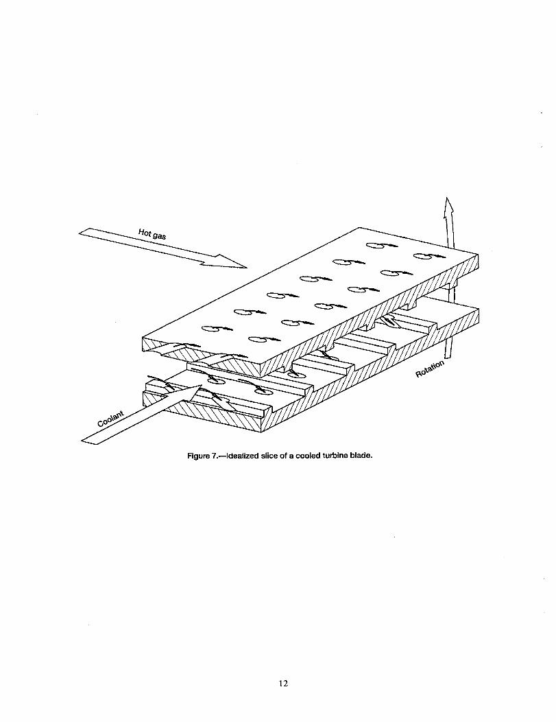
Figure 7.--Idealized slice of a cooled turbine blade.
12

V
i
:: L_\:.:.-_iE:
(a)
R
• im
, m
](,.41h
lllll, mSa
|m
ll
film
,,,,/,-
,,,,.,p',
Lm,_
Internal coolant flow
00 5 "10
(b)
Figure 8.--Use of GRIDPRO Multiblock code for the analysis of the branched duct experiment, (a) 283 block
topology reduced to 27 blocks. (b) Full grid.
13
15
10
(a)
0-10
60 0
150-- .
-5 0 5 10 15
r-- Separation region/
' i/
I I
Recirculation region --\\ _ _ _ _ _6 _ _ _
(b)
Figure 9.--Heat transfer in the branched duct (Re = 335,000). (a) Analysis, using Baldwin-Lomax turbulence model.(b) Experimental heat transfer coefficients 0N/m2/K).
14
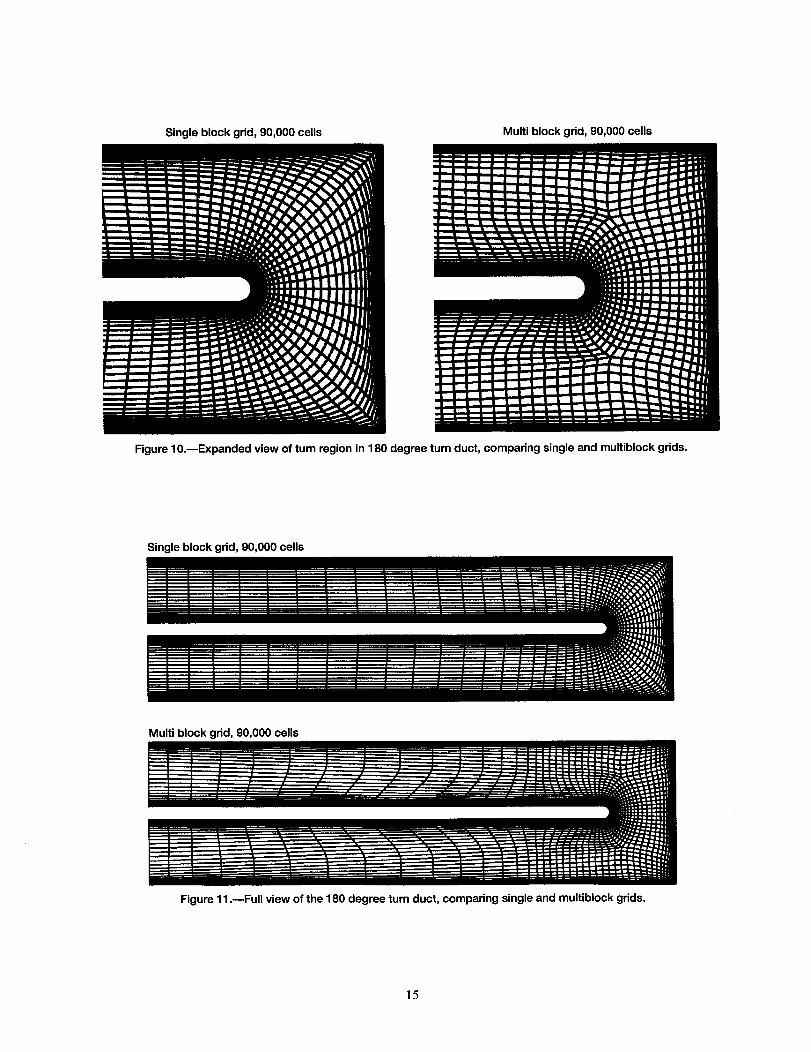
Single block grid, 90,000 cells Multi block grid, 90,000 cells
Figure lO.mExpanded view of tum region in 180 degree turn duct, comparing single and multiblock grids.
Single block grid, 90,000 cells
Multi block grid, 90,000 cells
Figure 11 .mFull view of the 180 degree turn duct, comparing single and multiblock grids.
15

Single block grid, 270,000 cells
Multi block grid, 90,000 cells
Internal coolant flow
Figure 12.--Normalized Nusselt number on lower surface of the 180 ° tum duct, using single and
multiblock grids (Re = 18,000, aspect ratio = 0.5, fully developed inlet).
Experiment, Arts et al.
Multi block grid, 90,000 cells
÷
Internal coolant flow
Figure 13.--Normalized Nusselt number on lower surface of the 180 ° turn duct, comparing experimentand analysis (Re = 18,000, aspect ratio = 0.5, fully developed inlet).
16
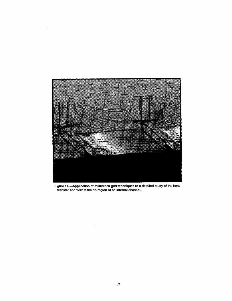
Figure 14.--Application of multiblock grid techniques to a detailed study of the heat
transfer and flow in the rib region of an internal channel.
17
"0
e-c
.C
0_
00
E
T-
LL
O0
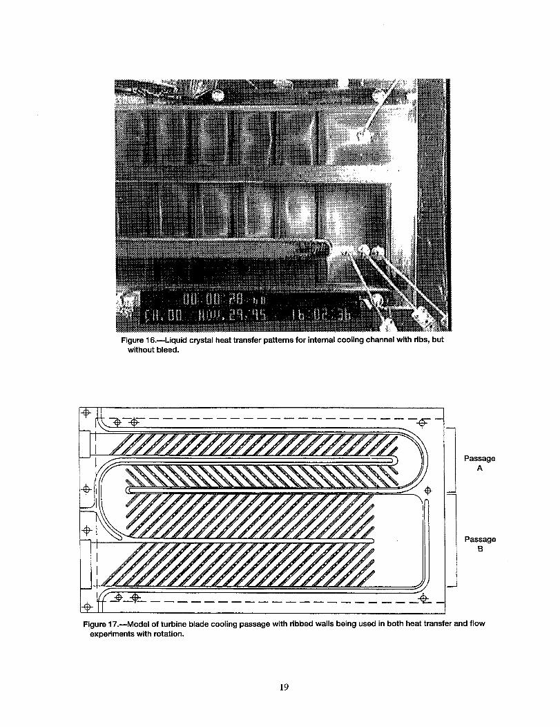
Figure 16.mLiquid crystal heat transfer patterns for internal cooling channel with ribs, butwithout bleed.
I
I PassageA
PassageB
Figure 17.reModel of turbine blade cooling passage with ribbed walls being used in both heat transfer and flow
experiments with rotation.
]9
0)C
0m
2
0
.mf4-
_ C
,(d
• -_ 0)
LL

(a)
/7 Baffle /_ Film cooling
Freestream_ Film cooling hole (cross section)
/ f- Baffle /Film cooling / _ /
supply plenum/ / _/_/
Freestream "'-(b) _._ _ Film cooling hole (cross section)
Figure 19.---Sketch of experiment to study bleed region flow effect on film coolantflow. (a) Counter-to-freestream. (b) Parallel-to-freestream.
20--
16--
>,12--gw
gUl 8--
4--
X/D 0/D
A 2.5 0.06673
[] 5 0.0913
© 10 0.11142
O
[]
0
0
[]
0
a
[]
a
[]
A
A
0 I I I I I0 2 4 6 8 10
y/0
Figure 20.--Eddy diffusivity ratio in the region near a film cooling hole with a fully
developed inlet.
21
2.0
1.9
1.8
1.7
1.6
O¢-
1.5
1.4
1.3
1.2
1.1
1.0
\_ \
Tu Lu, Rex VRcm
•12 3.36 820,000 1.5•12 3.36 814,000 1.0•12 3.36 814,000 0.5
•124 3.16 531,000 1.0
m
I t I0 10 20 30 40 50 60 70
X/D
Figure 21 .mPressure surface blown over unblown heat transfer ratio (local values) for a range of velocityratios with high turbulence, 2 rows, 30 °, S/D = 3.
1°8 --
1.6 --
1.4
1.2 --
_ 1.0
0.8
0.6
0.4--
0.2--
0.00
VR Rex
__ ---O---- 1.5
--_£3_ 1.0 820,000m-_---- 0.5
-- -O--- 1.0 530,000
_ Average
I I I I I I I10 20 30 40 50 60 70
X/D
Figure 22._lnfluence of turbulence on relative level of pressure surface adiabatic effectiveness, 2 rows, 30 °,S/D = 3.
22
Taw/To1.0
Hub
RotorO.D.=5ftHub/tipratio=0.8Numberofblades=28
=5200rpmmc/mo=3.65%
Tc/To = 0.5
0.7
0.4
Coolant particle traces fromshower-head holes on the
suction side; adiabatic walltemperature ratio contoursshown on the blade surface
Shower head
injection towards
the blade tip
UTRC rotor
with 5 rows of
83 film-cooling holes
Figure 23.--_Computational film cooling.
Adiabaticeffectiveness
1.0
O, = 5200 rpm
Tc/T o = 0.50.5 mc/mo = 3.65%
Ic/I o = 3.55%
0.0
Hub
Tip (a)
Tip
Tip
Tip
Tip
Hub
I'ip Tip
(b) (c)
Figure 24.--Use of CFD to study the effect of coolant injection pattern on film coolingeffectiveness m UTRC rotor. (a) All shower-head holes inject towards the hub. (b) All shower-
head holes inject towards the tip. (c) All shower-head holes inject towards tip except 8 nearhub on suction side that inject towards hub.
23
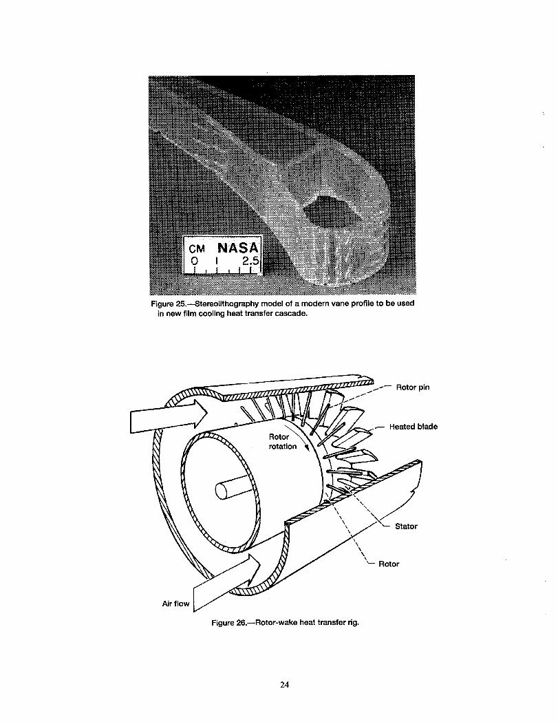
Figure 25.---Stereolithography model of a modern vane profile to be used
in new film cooling heat transfer cascade.
Air fl0
Figure 26.mRotor-wake heat transfer rig.
Heated blade
Stator
\\
_-- Rotor
24

• Annular turbine cascade
• Film-cooled test blade
• 5 staggered rows of holes
• 30 ° spanwise ejection angle
• Spoked-wheel wake generator
• Measurement of T(t) on blade
Figure 27.mTime-resolved effect of wake passing on turbine film cooling.
25

Form ApprovedREPORT DOCUMENTATION PAGE OMBNo. 0704-0188
Public reporting burden for this collection of information is estimated to average 1 hour per response, including the time for reviewing instructions, searching existing data sources,gathering and maintaining the data needed, and completing and reviewing the collection of information. Send comments re larding this burden estimate or any other aspect of thiscollection of information, including suggestions for reducing this burden, to Washington Headquarters Services, Directorate for Information Operations and Reports, 1215 JeffersonDavis Highway, Suite 12()4, Arlington, VA 22202-4302, and to the Office of Management and Budget, Paperwork Reduction Project (0704-0188), Washington, DC 20503.
1. AGENCY USE ONLY (Leave blank) 2. REPORT DATE 3. REPORT TYPE AND DATES COVERED
March 1996 Technical Memorandum
5. FUNDING NUMBERS4. TITLE AND SUBTITLE
Research Strategy for Modeling the Complexities of Turbine Heat Transfer
6. AUTHOR(S)
Robert J. Simoneau
7. PERFORMING ORGANIZATION NAME(S) AND ADDRESS(ES)
National Aeronautics and Space Administration
Lewis Research Center
Cleveland, Ohio 44135-3191
9. SPONSORING/MONITORING AGENCY NAME(S) AND ADDRESS(ES)
National Aeronautics and Space Administration
Washington, D.C. 20546 - 0001
WU-505-62-52
8. PERFORMING ORGANIZATIONREPORT NUMBER
E-10109
10. SPONSORING/MONITORINGAGENCY REPORT NUMBER
NASA TM-107161
11. SUPPLEMENTARY NOTES
Prepared for the International Conference on Turbulent Heat Transfer sponsored by the Engineering Foundation, San
Diego, California, March 10-15, 1996. Responsible person, Robert J. Simoneau, organization code 2630, (216) 433-5883.
12a. DISTRIBUTION/AVAILABILITY STATEMENT
Unclassified - Unlimited
Subject Category 34
This publication is available from the NASA Center for Aerospace Information, (301) 621_)390.
12b. DISTRIBUTION CODE
13. ABSTRACT (Maximum 200 words)
There is no shortage of complex heat transfer problems, so the title problem is merely one with which the author is familiar and
one for which we have a nice story to tell. Being more specific, the subject of this paper is a NASA research program, known as
the Coolant Flow Management Program, which focuses on the interaction between the internal coolant channel and the external
film cooling of a turbine blade and/or vane in an aircraft gas turbine engine. The turbine gas path is really a very complex flow
field. The combination of strong pressure gradients, abrupt geometry changes and intersecting surfaces, viscous forces, rotation,
and unsteady blade/vane interactions all combine to offer a formidable challenge. To this, in the high pressure turbine, we add
the necessity of film cooling. The ultimate goal of the turbine designer is to maintain or increase the high level of turbine
performance and at the same time reduce the amount of coolant flow needed to achieve this end. Simply stated, coolant flow is a
penalty on the cycle and reduces engine thermal efficiency. Accordingly, understanding the flow field and heat transfer associ-
ated with the coolant flow is a priority goal. It is important to understand both the film cooling and the internal coolant flow,
particularly their interaction. Thus, the motivation for the Coolant Flow Management Program. The paper will begin with a brief
discussion of the management and research strategy, will then proceed to discuss the current attack from the internal coolant
side, and will conclude by looking at the film cooling effort - at all times keeping sight of the primary goal the interaction
between the two. One of the themes of this paper is that complex heat transfer problems of this nature cannot be attacked by
single researchers or even groups of researchers, each working alone. It truly needs the combined efforts of a well-coordinated
team to make an impact. It is important to note that this is a government/industry/university team effort.
14. SUBJECT TERMS
Heat transfer; Turbulence; Turbine cooling; Film cooling
17. SECURITY CLASSIFICATIONOF REPORT
Unclassified
NSN 7540-01-280-5500
18. SECURITY CLASSIFICATIONOF THIS PAGE
Unclassified
19. SECURITY CLASSIFICATIONOF ABSTRACT
Unclassified
15. NUMBER OF PAGES
27
16. PRICE CODE
A03
20. LIMITATION OF ABSTRACT
Standard Form 298 (Rev. 2-89)PrescribedbyANSI Std. Z39-1B298-102

National Aeronautics and
Space Administration
Lewis Research Center
21000 Brookpark Rd.Cleveland, OH 44135-3191
Official Business
Penalty for Private Use $300
POSTMASTER: If Undeliverable-- Do Not Return