reservoir engineering - gate in · pdf filereservoir engineering general british thermal units...
TRANSCRIPT

© All rights reserved by Gate In Petroleum Pvt. Ltd. No part of this document may be reproduced or utilized in any form
without the written permission. www.gateinpetroleum.com
RESERVOIR ENGINEERING
General
British thermal units (BTU)
Structural arrangement of hydrocarbons includes: open chain and cyclic chain
Remaining two categories refer to the bonds between carbon atoms: saturated (ane)
and unsaturated (ene) hydrocarbon
Unsaturated hydrocarbons: double bond between carbon atoms
Ring or cyclic compound is designated by adding the prefix ‘cyclo’
Paraffin Alkane
Olefin Alkene
Cycloalkane
Aromatics
SG of crude oil ranges from 0.75 to 1.01. Density of crude oils also measured in
API units.
𝑨𝑷𝑰 = (𝟏𝟒𝟏. 𝟓
𝜸) − (𝟏𝟑𝟏. 𝟓)
Absolute viscosity (cp) of crude is obtained by multiplying kinematic viscosity
(cS) with the density of material (g/cc)
Dynamic viscosity: Its measure of internal resistance. Dynamic viscosity is
tangential force required per unit area required to move on one horizontal plane
with respect to other plane. Dynamic viscosity can be obtained from Newton’s law:
𝝉 = 𝝁 ∗ (∆𝒗
∆𝒍)
𝑤ℎ𝑒𝑟𝑒 𝜏 𝑖𝑠 𝑠ℎ𝑒𝑎𝑟 𝑠𝑡𝑟𝑒𝑠𝑠 (𝑁
𝑚2) , ∆𝑣 𝑖𝑠 𝑣𝑒𝑙𝑜𝑐𝑖𝑡𝑦 (
𝑚
𝑠) , ∆𝑙 𝑖𝑠 𝑢𝑛𝑖𝑡 𝑑𝑖𝑠𝑡𝑛𝑎𝑐𝑒 𝑏𝑒𝑡𝑤𝑒𝑒𝑛 𝑙𝑎𝑦𝑒𝑟𝑠 (𝑚)
Unit of dynamic viscosity is poise or centipoise (Pa s)
Kinematic viscosity is the ratio of dynamic viscosity to density. It’s a quantity in
which no force is involved.

© All rights reserved by Gate In Petroleum Pvt. Ltd. No part of this document may be reproduced or utilized in any form
without the written permission. www.gateinpetroleum.com
𝜗 = 𝜇/𝜌
Unit of kinematic viscosity is stoke or centistoke.
Crude oils are classified on the basis of bases:
1. Paraffin based- oil predominantly containing paraffin based series
hydrocarbons
2. Asphalt based- oil predominantly containing polymethylene or olefin series.
3. Mixed based
Fundamental properties of rocks
Porosity: a measure of the space available for storage of hydrocarbons in rock.
∅ =𝑉𝑣𝑜𝑖𝑑
𝑉𝑏𝑢𝑙𝑘
Porosities are classified on the basis of type of origin: primary porosity and
secondary porosity (induced porosity).
Original porosity is that developed in material during deposition and while induced
porosity is due to geologic process subsequent to deposition of rock. Original
porosity is classified by intergranular porosity of sandstones and intercrytalline
and oolitic porosity of some limestone.

© All rights reserved by Gate In Petroleum Pvt. Ltd. No part of this document may be reproduced or utilized in any form
without the written permission. www.gateinpetroleum.com
Cubic packing porosity:
The unit cell cube is with sides equal to 2r where r is radius of sphere.
Therefore bulk volume:
𝑏𝑢𝑙𝑘 𝑣𝑜𝑙𝑢𝑚𝑒 = (2𝑟)2 = 8𝑟3
Since there are 8 spheres in single unit cell:
𝑠𝑎𝑛𝑑 − 𝑔𝑟𝑎𝑖𝑛 𝑣𝑜𝑙𝑢𝑚𝑒 =4𝜋𝑟3
3
𝑝𝑜𝑟𝑒 𝑣𝑜𝑙𝑢𝑚𝑒
𝑏𝑢𝑙𝑘 𝑣𝑜𝑙𝑢𝑚𝑒=
𝑏𝑢𝑙𝑘 𝑣𝑜𝑙𝑢𝑚𝑒 − 𝑔𝑟𝑎𝑖𝑛 𝑣𝑜𝑙𝑢𝑚𝑒
𝑏𝑢𝑙𝑘 𝑣𝑜𝑙𝑢𝑚𝑒=
8𝑟3 − (4𝜋𝑟3
3)
8𝑟3

© All rights reserved by Gate In Petroleum Pvt. Ltd. No part of this document may be reproduced or utilized in any form
without the written permission. www.gateinpetroleum.com
Rhombohedral packing:
Total porosity is ratio of total void space in rock to bulk volume of rock. Effective
porosity is ratio of interconnected void space in rock to bulk volume of rock.
Porosity measurements: bulk volume of the sample can be measured from
measuring dimensions of the sample.
Porosity by saturation method -
a. Weight of dry sample in air
b. Weight of sample when saturated with water
c. Weight of water is difference between b-a
d. Weight of water/density of water = volume of water (effective pore volume)
e. Bulk volume from dimensions
f. Effective porosity = (pore volume/bulk volume)
Porosity averaging technique:
Arithmetic Average ∅ =
∅1 + ∅2 + ∅3 + ⋯
𝑛
Thickness weighted average ∅ =
∅1 ∗ ℎ1 + ∅2 ∗ ℎ2 + ∅3 ∗ ℎ3 + ⋯
ℎ1 + ℎ2 + ℎ3 + ⋯
Area weighted average ∅ =
∅1 ∗ 𝐴1 + ∅2 ∗ 𝐴2 + ∅3 ∗ 𝐴3 + ⋯
𝐴1 + 𝐴2 + 𝐴3 + ⋯
Volumetric weighted average ∅ =
∅1 ∗ 𝐴1 ∗ ℎ1 + ∅2 ∗ 𝐴2 ∗ ℎ2 + ⋯
𝐴1 ∗ ℎ1 + 𝐴2 ∗ ℎ2 + ⋯
Permeability: fluid conductance capacity of formation is permeability.
Permeability is property of porous medium and is measure as capacity of medium
to transmit fluids.
© All rights reserved by Gate In Petroleum Pvt. Ltd. No part of this document may be reproduced or utilized in any form
without the written permission. www.gateinpetroleum.com
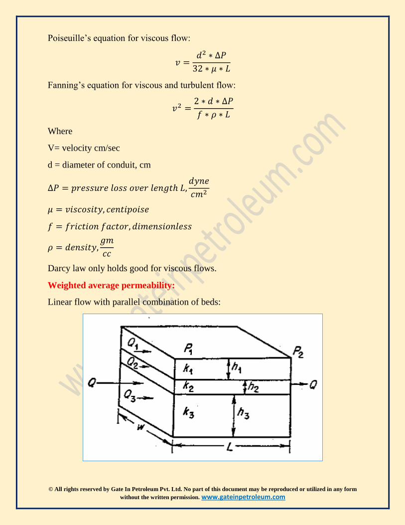
Poiseuille’s equation for viscous flow:
𝑣 =𝑑2 ∗ ∆𝑃
32 ∗ 𝜇 ∗ 𝐿
Fanning’s equation for viscous and turbulent flow:
𝑣2 =2 ∗ 𝑑 ∗ ∆𝑃
𝑓 ∗ 𝜌 ∗ 𝐿
Where
V= velocity cm/sec
d = diameter of conduit, cm
∆𝑃 = 𝑝𝑟𝑒𝑠𝑠𝑢𝑟𝑒 𝑙𝑜𝑠𝑠 𝑜𝑣𝑒𝑟 𝑙𝑒𝑛𝑔𝑡ℎ 𝐿,𝑑𝑦𝑛𝑒
𝑐𝑚2
𝜇 = 𝑣𝑖𝑠𝑐𝑜𝑠𝑖𝑡𝑦, 𝑐𝑒𝑛𝑡𝑖𝑝𝑜𝑖𝑠𝑒
𝑓 = 𝑓𝑟𝑖𝑐𝑡𝑖𝑜𝑛 𝑓𝑎𝑐𝑡𝑜𝑟, 𝑑𝑖𝑚𝑒𝑛𝑠𝑖𝑜𝑛𝑙𝑒𝑠𝑠
𝜌 = 𝑑𝑒𝑛𝑠𝑖𝑡𝑦,𝑔𝑚
𝑐𝑐
Darcy law only holds good for viscous flows.
Weighted average permeability:
Linear flow with parallel combination of beds:

© All rights reserved by Gate In Petroleum Pvt. Ltd. No part of this document may be reproduced or utilized in any form
without the written permission. www.gateinpetroleum.com
𝑄𝑡 = 𝑄1 + 𝑄2 + 𝑄3
ℎ𝑡 = ℎ1 + ℎ2 + ℎ3
𝑄1 = (𝑘1 ∗ 𝑤 ∗ ℎ1
𝜇) (
∆𝑃
∆𝐿)
𝑄2 = (𝑘2 ∗ 𝑤 ∗ ℎ2
𝜇) (
∆𝑃
∆𝐿)
𝑄3 = (𝑘3 ∗ 𝑤 ∗ ℎ3
𝜇) (
∆𝑃
∆𝐿)
𝑄𝑡 = (𝑤
𝜇) ∗ (
∆𝑃
∆𝐿) ∗ (𝑘1ℎ1 + 𝑘2ℎ2 + 𝑘3ℎ3)
𝐾𝑎𝑣𝑒 ∗ ℎ𝑡 = 𝑘1ℎ1 + 𝑘2ℎ2 + 𝑘3ℎ3
𝑲𝒂𝒗𝒆 =𝒌𝟏𝒉𝟏 + 𝒌𝟐𝒉𝟐 + 𝒌𝟑𝒉𝟑
𝒉𝟏 + 𝒉𝟐 + 𝒉𝟑
Permeability of parallel layered system is given by above equation.
Harmonic average permeability:

© All rights reserved by Gate In Petroleum Pvt. Ltd. No part of this document may be reproduced or utilized in any form
without the written permission. www.gateinpetroleum.com
Permeability variations occurring laterally in reservoir flow through series
combination of beds.
In this case, flow rate across the beds will be same. The change will be in the
pressure drop across the beds.
∆𝑃𝑡𝑜𝑡𝑎𝑙 = ∆𝑃1 + ∆𝑃2 + ∆𝑃3
(𝑄𝜇𝐿
𝐴𝐾𝑎𝑣𝑔) = (
𝑄𝜇𝐿1
𝐴𝐾1) + (
𝑄𝜇𝐿2
𝐴𝐾2) + (
𝑄𝜇𝐿3
𝐴𝐾3)
(𝐿
𝐾𝑎𝑣𝑔) = (
𝐿1
𝐾1) + (
𝐿2
𝐾2) + (
𝐿3
𝐾3)
𝑲𝒂𝒗𝒈 =𝑳
(𝑳𝟏
𝑲𝟏) + (
𝑳𝟐
𝑲𝟐) + (
𝑳𝟑
𝑲𝟑)
Permeability series layered system given by above equations.
Geometric average permeability:
𝑲𝒂𝒗𝒈 = 𝒆𝒙𝒑 (𝒉𝟏 ∗ 𝒍𝒏(𝒌𝟏) + 𝒉𝟐 ∗ 𝒍𝒏(𝒌𝟐) + ⋯
𝒉𝟏 + 𝒉𝟐 + ⋯)
For heterogeneous formation, geometric average permeability is widely used.
Plugs cut parallel to bedding planes gives horizontal permeability while plugs
cut perpendicular to bedding plane gives vertical permeability.
Multiphase permeability:
Permeability measured with 100 % saturation of a single phase is called the
absolute permeability of rock.
Effective permeability is permeability of phase when core is saturated with
two or more phases. Sum of effective permeability is always less than or equal
to absolute permeability.
Relative permeability is ratio of effective permeability to given fluid at definite
saturation to a given fluid at 100 % (absolute permeability) saturation.

© All rights reserved by Gate In Petroleum Pvt. Ltd. No part of this document may be reproduced or utilized in any form
without the written permission. www.gateinpetroleum.com
Klinkenberg effect:
Liquids has zero velocity on grain surface, while gases has some finite velocity
at the sand grain surface i.e. gases exhibits slippage at the surface. This
slippage resulted n higher flow rate for the gas at given pressure differential.
𝑲𝒈𝒂𝒔 = 𝑲𝒍𝒊𝒒𝒖𝒊𝒅 + 𝑪 ∗ (𝟏
𝑷𝒎)
Porosity-permeability relationship:
Timur equation:
𝑲 = 𝟖. 𝟓𝟖𝟏𝟎𝟐 ∗ (∅𝟒.𝟒
𝑺𝟐𝒘𝒄)
Morris-Biggs equation:
𝑲 = 𝟔𝟐. 𝟓 ∗ (∅𝟑
𝑺𝒘𝒄)
𝟐
− 𝒇𝒐𝒓 𝒐𝒊𝒍 𝒓𝒆𝒔𝒆𝒓𝒗𝒐𝒊𝒓
𝑲 = 𝟐. 𝟓 ∗ (∅𝟑
𝑺𝒘𝒄)
𝟐
− 𝒇𝒐𝒓𝒈𝒂𝒔 𝒓𝒆𝒔𝒆𝒓𝒗𝒐𝒊𝒓

© All rights reserved by Gate In Petroleum Pvt. Ltd. No part of this document may be reproduced or utilized in any form
without the written permission. www.gateinpetroleum.com
𝒌 =∅ ∗ 𝒓𝟐
𝟖
Permeability determination in laboratory:
Core plug is de-saturated completely before testing. Gas Is flowed through the
core at known differential pressure and flow rate.
Values are plotted as per given in above graph. From Darcy law, then
permeability of core is found out.
Relation between Poiseuille’s equation and Darcy law:
Flow through channels:
Poiseuille’s equation:
𝑸 =𝝅𝒓𝟒 ∗ ∆𝑷
𝒇 ∗ 𝝆 ∗ ∆𝑳 𝒐𝒓
𝝅𝒓𝟒 ∗ ∆𝑷
𝟖𝝁∆𝑳
Darcy law:
𝑸 =𝑲 ∗ 𝝅𝒓𝟐 ∗ ∆𝑷
𝝁 ∗ ∆𝑳

© All rights reserved by Gate In Petroleum Pvt. Ltd. No part of this document may be reproduced or utilized in any form
without the written permission. www.gateinpetroleum.com
Equating both the equations:
𝑲 ∗ 𝝅𝒓𝟐 ∗ ∆𝑷
𝝁 ∗ ∆𝑳=
𝝅𝒓𝟒 ∗ ∆𝑷
𝟖𝝁∆𝑳
𝑲 =𝒓𝟐
𝟖
Flow through fractures:
∆𝑷 =𝟏𝟐 ∗ 𝝁 ∗ 𝒗 ∗ 𝑳
𝒉𝟐
Comparing equation with Darcy law, then
𝒌 =𝒉𝟐
𝟏𝟐
Use of capillary tubes for flow network:
If conductors are of same size and are arrange in cubic arrangement, then
neglecting wall thickness of tubes, the number of tubes per unit area,
𝒑𝒐𝒓𝒐𝒔𝒊𝒕𝒚
𝒂𝒓𝒆𝒂=
𝝅
𝟒
𝝅𝒓𝟐
Then flow rate can be given by,
𝑸 = 𝒏 ∗𝝅𝒓𝟒 ∗ ∆𝑷
𝟖𝝁∆𝑳
𝑸 = (𝟏
𝟒𝒓𝟐) ∗
𝝅𝒓𝟒 ∗ ∆𝑷
𝟖𝝁∆𝑳
Comparing equation with Darcy law then,
𝑲 = (𝝅𝒓𝟐
𝟑𝟐)
Kozeny karman equation:
𝒌 = ( ∅
𝑲𝒛 ∗ 𝑺𝟐𝒑)
Where,

© All rights reserved by Gate In Petroleum Pvt. Ltd. No part of this document may be reproduced or utilized in any form
without the written permission. www.gateinpetroleum.com
∅ 𝒊𝒔 𝒑𝒐𝒓𝒐𝒔𝒊𝒕𝒚, 𝑲𝒛 𝒊𝒔 𝒌𝒐𝒛𝒆𝒏𝒚 𝒄𝒐𝒏𝒔𝒕𝒂𝒏𝒕 & 𝑆𝑝 𝑖𝑠 𝑠𝑢𝑟𝑓𝑎𝑐𝑒 𝑎𝑟𝑒𝑎 𝑝𝑒𝑟 𝑢𝑛𝑖𝑡 𝑝𝑜𝑟𝑒 𝑣𝑜𝑙𝑢𝑚𝑒
𝝉 = (𝑳𝒂
𝑳) = 𝑻𝒐𝒓𝒕𝒖𝒐𝒔𝒊𝒕𝒚
𝑲𝒛 = 𝑲𝒐 ∗ 𝝉 = 𝒌𝒐𝒛𝒆𝒏𝒚 𝒄𝒐𝒏𝒔𝒕𝒂𝒏𝒕
Fluid saturations:
Methods to estimate fluid saturation:
a. Retort method- core is placed in retort chamber. Trapped fluid in core
is then carried away by toluene vapors. Condensation of vapors gives
volume of hydrocarbons present in core.
𝑺𝒘 =𝒘𝒂𝒕𝒆𝒓 𝒓𝒆𝒄𝒗𝒆𝒓𝒆𝒅
𝒑𝒐𝒓𝒆 𝒗𝒐𝒍𝒖𝒎𝒆
𝑺𝒐 =𝑶𝒊𝒍 𝒓𝒆𝒄𝒗𝒆𝒓𝒆𝒅
𝒑𝒐𝒓𝒆 𝒗𝒐𝒍𝒖𝒎𝒆
𝑺𝒈 = 𝟏 − 𝑺𝒘 − 𝑺𝒐
In leaching with toluene gives indirect oil saturation calculation,
𝑺𝒐 =𝑾𝒆𝒕 𝒄𝒐𝒓𝒆 𝒘𝒕 (𝒈𝒎). −𝒅𝒓𝒚 𝒄𝒐𝒓𝒆 𝒘𝒕(𝒈𝒎). −𝒘𝒕. 𝒐𝒇𝒘𝒂𝒕𝒆𝒓 𝒄𝒐𝒍𝒍𝒆𝒄𝒕𝒆𝒅(𝒈𝒎)
𝒑𝒐𝒓𝒆 𝒗𝒐𝒍𝒖𝒎𝒆 (𝒄𝒄) ∗ 𝒅𝒆𝒏𝒔𝒊𝒕𝒚 𝒐𝒇 𝒐𝒊𝒍(𝒈𝒎
𝒄𝒄)
b. Centrifuge
A solvent is injected into the centrifuge. Solvent is being forced to pass
through the core sample, removes water and oil from the core.
Water saturations obtained from core samples cut with oil-based are the
reliable. Core-samples cut with water based mud are used to determine
original gas-oil contact, original oil-water contact & whether sand is
productive of oil or gas. Contacts can be determined by careful study the
residual oil saturation of cores as function of depth.

© All rights reserved by Gate In Petroleum Pvt. Ltd. No part of this document may be reproduced or utilized in any form
without the written permission. www.gateinpetroleum.com
Electrical conductivity of fluid saturated rocks:
Resistivity of material
𝝆 =𝒓 ∗ 𝑨
𝑳
𝝆 𝒊𝒔 𝒓𝒆𝒔𝒊𝒔𝒕𝒊𝒗𝒊𝒕𝒚, 𝒓 𝒊𝒔 𝒓𝒆𝒔𝒊𝒔𝒕𝒂𝒏𝒄𝒆, 𝑨 𝒊𝒔 𝒂𝒓𝒆𝒂, 𝑳 𝒊𝒔 𝒍𝒆𝒏𝒈𝒕𝒉
Resistivity in rocks measured in terms of ohm-meter.
Formation factor:
𝑭 =𝑹𝒐
𝑹𝒘
Resistivity factor is ratio of resistivity of rock when saturated with water to
the resistivity of water.
Resistivity index is ratio of resistivity of rock partially saturated water to
resistivity of 100 % saturated water.
𝑰 =𝑹𝒕
𝑹𝒐
Properties of material with porous media containing multiple fluid
saturations:
Surface forces and capillary pressure:
Interfacial tension is defined as work necessary to create a new surface.
Interfacial tension is the force per unit length required to create a new
surface.

© All rights reserved by Gate In Petroleum Pvt. Ltd. No part of this document may be reproduced or utilized in any form
without the written permission. www.gateinpetroleum.com
Contact angle is measured through denser phase and ranges from zero degree
to 180 degree.
𝝈𝒔𝒘 + 𝝈𝒘𝒐. 𝒄𝒐𝒔𝜽 = 𝝈𝒔𝒐
𝒄𝒐𝒔𝜽 =𝝈𝒔𝒐 − 𝝈𝒔𝒘
𝝈𝒘𝒐
Interfacial tension between solid and denser phase, solid and lighter phase &
denser and lighter fluid.
Magnitude of adhesion tension can be estimated by above given formula. If
adhesion tension value is large or the contact angle 𝜽 is small then, denser
phase will spread and tend to coat the surface.
Rise of fluids in capillaries: the rise in height is due to attractive forces
between the tube and liquid. The adhesion tension is force tending to pull
liquid up the wall of the tube. Liquid will be balanced by the total force acting
to pull liquid upward.
𝑨𝒓 ∗ 𝟐𝝅𝒓 = 𝒇𝒐𝒓𝒄𝒆 𝒖𝒑
The weight of fluid being supported by,
𝝅𝒓𝟐 ∗ 𝒉 ∗ 𝝆 ∗ 𝒈 = 𝒇𝒐𝒓𝒄𝒆 𝒅𝒐𝒘𝒏𝒘𝒂𝒓𝒅
𝑨𝒕 = 𝒂𝒅𝒉𝒆𝒔𝒊𝒐𝒏 𝒕𝒆𝒔𝒏𝒊𝒐𝒏,𝒅𝒚𝒏𝒆
𝒄𝒎

© All rights reserved by Gate In Petroleum Pvt. Ltd. No part of this document may be reproduced or utilized in any form
without the written permission. www.gateinpetroleum.com
𝒓 = 𝒓𝒂𝒅𝒊𝒖𝒔 𝒐𝒇 𝒕𝒖𝒃𝒆, 𝒄𝒎
𝒉 𝒊𝒔 𝒉𝒊𝒈𝒉𝒕 𝒐𝒇 𝒄𝒐𝒍𝒖𝒎𝒏, 𝒄𝒎
𝝆 𝒊𝒔 𝒍𝒊𝒒𝒖𝒊𝒅 𝒅𝒆𝒏𝒔𝒊𝒕𝒚 𝒊𝒏𝒈𝒎
𝒄𝒄
Equalizing forces,
𝑨𝒓 =𝒓 ∗ 𝒉 ∗ 𝒈 ∗ 𝝆
𝟐
Ar can be written as 𝝈𝒈𝒘. 𝒄𝒐𝒔𝜽 (interfacial tension between gas and water)
Distribution of fluid phase within porous system is described as funicular or
pendular. In funicular distribution, the wetting phase is continuous,
completely covering surface of solid. The pendular ring is state of saturation
in which wetting phase is non-continuous and non-wetting phase is in contact
with some solid surface.

© All rights reserved by Gate In Petroleum Pvt. Ltd. No part of this document may be reproduced or utilized in any form
without the written permission. www.gateinpetroleum.com
Saturation:
Movable oil saturation
𝑺𝒐𝒎 = 𝟏 − 𝑺𝒘𝒄 − 𝑺𝒐𝒄
Capillary pressure:
Capillary pressure is difference between pressure of non-wetting phase and
wetting-phase.
𝑷𝒄 = 𝑷𝒏𝒘 − 𝑷𝒘
It is difficult to use equations use for capillary tube to determine capillary
pressure in reservoir due to its complex nature of pores in reservoir. Capillary
pressure also viewed as necessary pressure to force non-wetting fluid to
displace wetting fluid in a capillary.
Capillary pressure curve as a function of water saturation for oil-water
system is given below in the diagram.

© All rights reserved by Gate In Petroleum Pvt. Ltd. No part of this document may be reproduced or utilized in any form
without the written permission. www.gateinpetroleum.com
The imbibitions curve present lower capillary pressure for fixed saturation
than drainage curve because natural tendency of wetting fluid to saturate
rock.
𝑭𝑾𝑳 = 𝑾𝑶𝑪 + (𝑷𝒄 ∗𝟏𝟒𝟒
∆𝝆)

© All rights reserved by Gate In Petroleum Pvt. Ltd. No part of this document may be reproduced or utilized in any form
without the written permission. www.gateinpetroleum.com
From the capillary rise equation,
𝒉 =𝟐𝝈𝒄𝒐𝒔∅
𝒓𝒈∆𝝆
As difference between density increases, the height of transition zone
decreases. In case of gas reservoir having a gas-water contact, the thickness of
transition zone will be shorter while for low API gravity oil, it will be longer.
Reserves estimation:
Petroleum resources classification and definitions: `

© All rights reserved by Gate In Petroleum Pvt. Ltd. No part of this document may be reproduced or utilized in any form
without the written permission. www.gateinpetroleum.com
Reserves- Those quantities of petroleum which are anticipated to be
commercially recovered from known accumulations from a give date forward.
Contingent Resource- those quantities of petroleum which are estimated, on a
given date, to be potentially recoverable from known accumulations, but
which are not currently considered to be commercially recoverable
Prospective Resource- Those quantities of petroleum which are estimated, on
a given date, to be potentially recoverable from undiscovered accumulations
Accumulation is used to identify an individual body of movable petroleum in a
reservoir.
Resource uncertainty in case of reserves is given as range. It is function of
primary three categories i.e. proved, probable and possible.
1P Proved
2P Proved + Probable
3P Proved + Probable + Possible
For other resource categories, the equivalent terms low estimate, best estimate
and high estimate are recommended.
Prospective resources
Prospect Potential accumulation sufficiently well-defined to represent
viable drilling target.
Lead Potentially accumulation is currently poorly defined and
requires more data acquisition and evaluation in order to
classify as prospect.
Play Recognized prospective trend of potential prospects, but which
requires more data acquisition to define leads or prospects.

© All rights reserved by Gate In Petroleum Pvt. Ltd. No part of this document may be reproduced or utilized in any form
without the written permission. www.gateinpetroleum.com
The entire resource based is generally accepted to be all those estimated
quantities of petroleum contained in sub-surface, as well as quantity
produced.
Total petroleum in place is sub-divided into ‘Discovered’ and ‘Un-discovered’
petroleum initial I place. Discovered petroleum may be classified as
‘commercial’ or ‘sub-commercial’.
Reserves must satisfy four criteria: discovered, recoverable, commercial &
remaining
Contingent resources are those discovered, potentially recoverable but don’t
satisfy criteria of commerciality.
Prospective resources are those potential recoverable quantities in
accumulation yet to be discovered.

© All rights reserved by Gate In Petroleum Pvt. Ltd. No part of this document may be reproduced or utilized in any form
without the written permission. www.gateinpetroleum.com
Converting gas volume to oil equivalent is customarily done the design basis
of heating content or calorific value of the fuel.
Probabilistic estimation procedures:
When probabilistic method are used there shall be at least 90 % probability
(P90) that the quantity actually recovered will exceed or level the estimate
quoted. There shall be at least 50 % probability (P50) that quantities actually
recovered will exceed sum of 2P reserves. Likewise, there shall be at least a
10% probability that 3P reserves will exceed or equaled.
P90 The quantity for which there is certain probability that the
quantities actually recovered will equal or exceed the estimate.
P50 The quantity for which there is 50 % probability that
quantities will actually recovered will equal or exceed the
estimate.
P10 The quantity for which there is 10 % probability that
quantities actually recovered will equal or exceed the estimate.
In applying probabilistic reserves estimation methods, SPE defines proved
reserves as having at least 90 % (P90) probability of exceeding the quoted
value. Proved reserves give conservative estimate hence its use by investors or
bankers.
Estimation methods:
Analogy methods:
Use to estimate ultimate recovery of oil and gas for undrilled locations.
𝑭𝒓𝒔 = 𝑭𝒓𝒂 ∗(∅ ∗ 𝑺𝒉𝒊)𝒔
(∅ ∗ 𝑺𝒉𝒊)𝒂
Here a stands for analogous reservoir while s stands for subject reservoir. Fr
is recovery factor.
Volumetric methods:
𝑵 =𝟕𝟕𝟓𝟖 ∗ ∅ ∗ 𝑨 ∗ 𝒉 ∗ (𝟏 − 𝑺𝒘𝒊)
𝑩𝒐∗ 𝑬𝒓
Most volumetric methods begin with determining bulk reservoir volume that
contains hydrocarbon. This involves preparation of structure maps of top and
bottom of the reservoir and iso-patch map of the reservoir.

© All rights reserved by Gate In Petroleum Pvt. Ltd. No part of this document may be reproduced or utilized in any form
without the written permission. www.gateinpetroleum.com
Estimating net pay is important steps in volumetric mapping. The net pay
should be determined on the basis of maximum shaliness, minimum porosity,
and maximum water saturation, specified reversal of gamma ray curve or SP
curve or combination of both.
For reserves to be proved, there should be at least 90 % probability that the
quantities actually recovered will equal or exceed the estimate. For probable
reserves, there should be at least 50 % probability that the quantity actually
recovered will equal or exceed the sum of estimated proved plus probable
reserves. For possible reserves, there at least should a 10 % probability that
quantities actually recovered will equal or exceed the sum of estimated
proved, probable and possible reserves.

© All rights reserved by Gate In Petroleum Pvt. Ltd. No part of this document may be reproduced or utilized in any form
without the written permission. www.gateinpetroleum.com
Decline trend analysis: estimating the reserves on the basis of a reasonable
well defined behavior of a performance characteristics as function of time of
cumulative production.
When flow boundary reaches actual reservoir boundary or meets with flow
boundary of another well, the reservoir pressure begins to decline and well
enters boundary dominated flow period. It is period that traditional decline
curve analysis can be used.

© All rights reserved by Gate In Petroleum Pvt. Ltd. No part of this document may be reproduced or utilized in any form
without the written permission. www.gateinpetroleum.com
Decline theory:
Fractional change per unit time is given as,
𝒂 = −
∆𝒒
𝒒
∆𝒕
𝒂 = − (𝟏
𝒒) (
∆𝒒
∆𝒕)
Another way to define is,
𝒂 = 𝑲. 𝒒𝒃
Exponential b = 0
𝒒 = 𝒒𝒊 ∗ 𝒆−𝒂∗𝒕
Cumulative production:
𝑸 = ∫ 𝒒. 𝒅𝒕
𝒕
𝟎
𝑸 = ∫ 𝒒𝒊 ∗ 𝒆−𝒂∗𝒕. 𝒅𝒕
𝒕
𝟎
𝑸 =𝒒𝒊 − 𝒆−𝒂∗𝒕
𝒂
𝑸 =𝒒𝒊 − 𝒒
𝒂
Hyperbolic b is equal to any number between
zero and one
𝒂 ⍺ 𝒒𝒃
𝒒 =𝒒𝒊
(𝟏 + 𝒃. 𝒂𝒊. 𝒕)𝟏
𝒃

© All rights reserved by Gate In Petroleum Pvt. Ltd. No part of this document may be reproduced or utilized in any form
without the written permission. www.gateinpetroleum.com
Cumulative production:
Harmonic b = 1
𝒂 = 𝑲. 𝒒𝟏
𝑲 =𝒂
𝒒
𝒒 =𝒒𝒊
𝟏 + 𝒂𝒊. 𝒕
Cumulative production:
𝑸 = ∫ 𝒒. 𝒅𝒕
𝒕
𝟎
𝑸 = ∫𝒒𝒊
𝟏 + 𝒂𝒊. 𝒕. 𝒅𝒕
𝒕
𝟎
𝑸 = (𝒒𝒊
𝒂𝒊) 𝒍𝒏 (
𝒒𝒊
𝒒)
Material balance: here pressure behavior in reservoir in response to fluid
withdrawal is analyzed in several steps. The fluid properties and pressure
history are averaged, treating reservoir as tank.

© All rights reserved by Gate In Petroleum Pvt. Ltd. No part of this document may be reproduced or utilized in any form
without the written permission. www.gateinpetroleum.com
Fundamentals of reservoir fluid flow:
Flow regimes
(http://fekete.com/SAN/TheoryAndEquations/WellTestTheoryEquations/inde
x.htm):
a. Wellbore storage (after flow)
When producing well is shut in at the surface, flow into wellbore at sand
face continues after shut in. wellbore storage is typically controlled by
compressibility of fluid.

© All rights reserved by Gate In Petroleum Pvt. Ltd. No part of this document may be reproduced or utilized in any form
without the written permission. www.gateinpetroleum.com
b. Linear fracture flow
Linear fracture flow occurs in hydraulically fractured wells when
conductivity of fracture is infinite. Permeability of fracture is so high
that the pressure throughout fracture is constant.
c. Bilinear fracture flow
Bilinear fracture flow occurs in hydraulically fractured wells when the
conductivity of fracture is finite. Flow one from matrix to fracture and
fracture to wellbore.

© All rights reserved by Gate In Petroleum Pvt. Ltd. No part of this document may be reproduced or utilized in any form
without the written permission. www.gateinpetroleum.com
d. Spherical flow
Spherical flow occurs when vertical well is partially penetrated or
during RFT/MDT/WFT tests.
e. Radial flow
Radial flow is in the horizontal radial direction. This type of flow
regime exists before the pressure transient reaching the boundaries of
reservoir (infinite acting time period).

© All rights reserved by Gate In Petroleum Pvt. Ltd. No part of this document may be reproduced or utilized in any form
without the written permission. www.gateinpetroleum.com
g. Single no-flow boundary
Single no-flow boundary occurs during transition region when well is
located near a single no-flow boundary. A no-flow boundary can be
physical entity, such as a sealing fault, or can occur when two producing
wells are adjacent wells.
Mathematically, a situation in which a well is next to a sealing fault can
be modeled by removing the fault and placing an image well with a flow
rate equivalent to producing well as shown in diagram below:
When single no-flow boundary flow is present, slope doubling can be seen in
derivative plots.

© All rights reserved by Gate In Petroleum Pvt. Ltd. No part of this document may be reproduced or utilized in any form
without the written permission. www.gateinpetroleum.com
h. Linear channel flow
Linear channel flow occurs in long, narrow reservoir. Initially the
radius of investigation hasn’t reached reservoir boundaries and radial
flow is observed. After the two parallel boundaries have been reached, a
period of linear flow can be observed.
© All rights reserved by Gate In Petroleum Pvt. Ltd. No part of this document may be reproduced or utilized in any form
without the written permission. www.gateinpetroleum.com
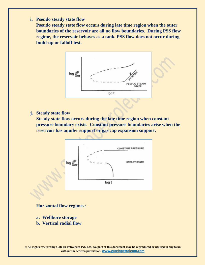
i. Pseudo steady state flow
Pseudo steady state flow occurs during late time region when the outer
boundaries of the reservoir are all no flow boundaries. During PSS flow
regime, the reservoir behaves as a tank. PSS flow does not occur during
build-up or falloff test.
j. Steady state flow
Steady state flow occurs during the late time region when constant
pressure boundary exists. Constant pressure boundaries arise when the
reservoir has aquifer support or gas cap expansion support.
Horizontal flow regimes:
a. Wellbore storage
b. Vertical radial flow

© All rights reserved by Gate In Petroleum Pvt. Ltd. No part of this document may be reproduced or utilized in any form
without the written permission. www.gateinpetroleum.com
Vertical radial flow occurs only in horizontal wells.
c. Linear horizontal
After the radius of investigation has reached the top and bottom of
the formation, fluid travels from the formation perpendicular to
length of the wellbore.

© All rights reserved by Gate In Petroleum Pvt. Ltd. No part of this document may be reproduced or utilized in any form
without the written permission. www.gateinpetroleum.com
d. Elliptical
Elliptical flow occurs when fluid has started to flow from the
reservoir at either end of the horizontal wellbore.
e. Horizontal radial
Horizontal radial occurs during middle time region after radius of
investigation has expanded beyond the length of wellbore.

© All rights reserved by Gate In Petroleum Pvt. Ltd. No part of this document may be reproduced or utilized in any form
without the written permission. www.gateinpetroleum.com
k. Linear channel
l. PSS
m. Steady state
Radius of investigation:
Radius of investigation is how far transient has travelled into the reservoir.
𝒓𝒊 = √𝒕 ∗ 𝒌
𝟗𝟒𝟖 ∗ ∅ ∗ 𝝁 ∗ 𝒄𝒕
Radius of investigation is only the function of reservoir properties and does
not depend on flow rate. Increasing flow rate will increases draw-down but
radius of investigation will be same.
Estimating drainage area:
𝑨 = (𝝅 ∗ 𝒓𝟐)
Estimate shut-in duration:
Time to stabilization: when pressure no longer changes with the time.
𝒕𝒔𝒕𝒂𝒃 = 𝒅𝒊𝒔𝒕𝒂𝒏𝒄𝒆 𝒕𝒐 𝒇𝒂𝒓𝒕𝒆𝒔𝒕 𝒃𝒐𝒖𝒏𝒅𝒂𝒓𝒚𝟐 ∗ (∅ ∗ 𝝁 ∗ 𝒄𝒕
𝒌)
Unsteady state flow:

© All rights reserved by Gate In Petroleum Pvt. Ltd. No part of this document may be reproduced or utilized in any form
without the written permission. www.gateinpetroleum.com
Second order partial differential equation has total three conditions, two
boundary conditions and one initial condition.
𝑩𝒐𝒖𝒏𝒅𝒂𝒓𝒚 𝒄𝒐𝒏𝒅𝒊𝒕𝒊𝒐𝒏𝒔: 𝒖(𝟎, 𝒕) = 𝟎, 𝒖(𝑳, 𝒕) = 𝟎
𝒊𝒏𝒊𝒕𝒊𝒂𝒍 𝒄𝒐𝒏𝒅𝒊𝒕𝒊𝒐𝒏𝒔: 𝒖(𝒙, 𝟎) = 𝒇(𝒙)
Boundary conditions: formation produces at constant rate into wellbore and
there is no flow across the outer boundary and reservoir behaves as if it’s
infinite in size.
Initial condition: reservoir is at uniform pressure when production begins.
Based on boundary conditions, there are two generalized solutions;
Constant terminal pressure solution
Constant terminal rate solution
Constant terminal pressure solution provides cumulative flow at any
particular time in reservoir in which pressure at one boundary held constant.
Constant terminal rate solution provides pressure change throughout the
reservoir when flow rate is held constant at one terminal end of radial system
i.e. producing well
Gas and water coning:
The critical production rate is a rate at which flowing pressure gradient in
well causes water or gas to cone into the well.
Coning can be eliminated by shallower penetration of well or by the
development of horizontal permeability.