residential & commercial product catalogue wood residential water heaters use one of three...
TRANSCRIPT

ProductCatalogueE l e c t r i c • G a s • O i l • T a n k l e s s
R e s i d e n t i a l & C o m m e r c i a l
©2012 GSW Water Heating.Printed in Canada 03/12 J309C
Joh
n W
oo
d® Pro
du
ct Catalo
gu
e
Head office:John Wood® 599 Hill Street WestFergus, ON N1M 2X1Tel: 1-888-599-2837Fax: 1-519-787-5500
Technical Support and Warranty:Tel: 1-888-479-8324
Sales/Customer Service:Tel: 1-888-599-2837
3 2 4 2 0 7 - 0 0 0
3 2 4 2 0 7 - 0 0 0
3 2 4 2 0 7 - 0 0 0
3 2 4 2 0 7 - 0 0 0
3 2 4 2 0 6 - 0 0 0

Visit www.johnwoodwaterheaters.com to access valuable information concerning John Wood® products and services such as:
• Parts Catalogue
• Warranty Validation
• ENERGY STAR® qualified products and rebate programs
• Information on products, including specifications and installation manuals
• Literature Request Form
• Frequently Asked Questions (FAQs)
• Exclusive Members Only Area
• Communication Request – sign up to receive email
notifications regarding Technical Bulletins, New
Products / Product News, Warranty Information and
Environmental Initiatives
Visit
online!

Table of ContentsJohn Wood Water Heaters 1
RESIDENTIAL PRODUCTS
John Wood Safety Systems 3
Atmospheric Vent (ENERGY STAR® Qualified) 4
Atmospheric Vent (Natural Gas) 6
Atmospheric Vent (Propane) 8
Power Vent (ENERGY STAR® Qualified) 10
Power Vent 12
Power Vent - Large capacity (75 USG) 14
Power Direct Vent 16
Direct Vent 18
Envirosense™ Power Direct Vent 20
Envirosense™ Power Vent 22
Polaris® 24
Residential Electric 26
SpaceSaver ® 28
Oil Fired & Oil Burners 30
Storage Booster Tanks 32
FlowTHRU® 34
Indirect Water Heaters 36
Range Boiler 38

Table of ContentsTANKLESS PRODUCTS
John Wood® powered by Takagi Tankless 39
COMMERCIAL PRODUCTS
John Wood Commercial Water Heaters 44
Commercial High Efficient Gas 45
Commercial Atmospheric Gas 47
Commercial Electric 49
Commercial Oil-Fired 51
Commercial Storage Tanks 53
Light Duty Commercial Gas 55
Light Duty Commercial Electric 57
Polaris® Commercial 59
APPENDICES
Cross-Over Matrix 61
Sizing Guide 62
Ohm’s Law 64
Reference Guide for Water Heating 65
Exclusive Designs, Service & Support 71
John Wood does not represent and/or warrant in any manner the information and suggestions contained in this brochure. John Wood maintains a policy of ongoing product improvement. This may result in modification of features and/or specifications without notice.

1
John Wood® Water Heaters
When you buy a John Wood water heater, you buy a quality, dependable, Canadian-made product. John Wood support is based on First Call, Final Resolution service. Our Care Technicians are driven to provide expert guidance, to identify the issue quickly and assist you until you’re satisfied. Support is available 24/7 with online resources, such as the Online Parts Catalogue, Warranty Validation, Product Information and Media Centre to help promote your business.

Natural Gas Models:• 0.62EF• Meetsorexceedsenergy efficiency requirements while maintaining same footprint.• TurbulatorTM dip tube to reduce sediment at bottom of tank.• 20%morefoam insulation than standard John Wood Atmospheric vent models.
Energy EfficientATMOSPHERIC VENTFeaturing the ‘Series 10’ gas valve
3 2 4 2 0 7 - 0 0 0
‘Series 10’ Gas Valve features:• Robustpilot• LED indicator light• Easiertemperature adjustment

Residential


3
John Wood® Safety SystemsFlammable Vapour Ignition Resistant (FVIR)
technology you can trust.
John Wood residential water heaters use one of three unique Flammable Vapour Ignition Resistant (FVIR) Safety Systems that reduce the risk of accidental fires caused by the ignition of flammable vapours from products such as gasoline, paint thinner and solvents: the Flame Guard® and Flame SafeTM Safety Systems and the Superflue Safety System.
Flame Guard® Safety System Used onJohn Wood Atmospheric Vent Water Heaters
The Flame Guard® Safety System is a recognized and proven technology used on John Wood used on Atmospheric Vent Water Heaters. The award winning Flame Guard® Safety System protects the consumer by trapping burning vapours within the
water heater combustion chamber through the patented “Flame-Trap.” As long as the vapours are present and within the flammability range, they will continue to burn safely until they “burn themselves out.”
Flame SafeTM Safety System Usedon John Wood Direct Vent Water Heaters
Flame SafeTM technology - designed to protect the consumer against the ignition of flammable vapours.
Superflue® Safety System Used on John Wood Power Vent Water Heaters
The Safety System used on John Wood Power Vent water heaters features a Flammable Vapour Sensor and air intake snorkel. This system not only shuts down the unit when flammable vapour are detected in the area of the water heater but elevates the air intake so that flammable vapours do not enter the combustion chamber and ignite before the sensor shuts down the water heater.

4
Atmospheric VentENERGY STAR® Qualified
• Same footprint as John Wood 40 & 50 USG ‘Series 10’ atmospheric vent models. Flue damper increases EF and performance.• 24 Volt gas valve. - Diagnostic capabilities. - Monitors damper for performance and safety. - Spark ignition.• Includes 20 ft. power cord (can be increased to 50 ft.)
3 2 4 2 0 7 - 0 0 0
PERFORMANCE
ModelCapacity Maximum
Certified Altitude InputBTU/hr
Recovery Rate at 100°F/55°C
Temp. Rise
First Hour Rating
Energy Factor
USG (L) ft (m) GPH/LPH USG (L)
NATURAL GAS
JW840S38ES2 40 (151) 4,500 (1,372) 38,000 34.5 (131) 70 (265) 0.67
JW640T40ES2 40 (151) 4,500 (1,372) 40,000 36 (137) 75 (284) 0.67
JW850S40ES2 50 (189) 4,500 (1,372) 40,000 36 (137) 90 (341) 0.68
JW650T40ES2 50 (189) 4,500 (1,372) 40,000 36 (137) 90 (341) 0.68

5
Atmospheric VentSpecifications
G E
F
DIM
ENSI
ONS &
SHIP
PING
WEI
GHT
Mod
el
Tank
Di
amet
erIn
stal
latio
n He
ight
Heig
ht to
Top
of Ta
nkHe
ight
to G
as
Inle
tHe
ight
to T&
PHe
ight
to
Drai
n Va
lve
Over
all D
epth
Draf
thoo
d Co
nnec
tor
Diam
eter
in
Appr
oxim
ate
Ship
ping
W
eigh
t
Ain
(cm
)B
in (c
m)
Cin
(cm
)D
in (c
m)
Ein
(cm
)F
in (c
m)
Gin
(cm
)lb
(kg)
NAT
URA
L G
AS
JW84
0S38
ES2
21 (5
3)55
3/4 (1
42)
49 (1
25)
12 1/2
(32)
42 1/2
(108
)9
1/2 (2
4)23
1/2 (6
0)3
- 414
1 (6
4)
JW64
0T40
ES2
19 (4
8)66
(168
)59
1/2 (1
51)
13 1/2
(34)
53 1/2
(136
)10
(25)
23 (5
9)3
- 413
5 (6
1)
JW85
0S40
ES2
22 1/2
(57)
57 1/4
(145
)50
1/2 (1
28)
12 3/4
(33)
44 (1
12)
11 (2
8)25
(64)
3 - 4
176
(80)
JW65
0T40
ES2
21 (5
3)64
3/4 (1
65)
58 (1
48)
12 1/4
(31)
52 (1
32)
12 (3
1)26
1/2 (6
7)3
- 416
8 (7
6)

Atmospheric Vent (Natural Gas)Proven Technology. Exceptional Reliability.
6
3 2 4 2 0 7 - 0 0 0
‘Series 10’ Model Shown
‘Series 10’ Models:• Thermopile design provides robust pilots to
withstand down drafts and environmental
conditions.
• LED indicator light lets you know when pilot
is in operation and provides diagnostic
capabilities.
• Easy temperature adjustment.
All Models:• Flameguard® Safety System.
• TurbulatorTM dip tube to reduce sediment on
bottom of tank.
PERFORMANCE
ModelCapacity Maximum
Certified Altitude InputBTU/hr
Recovery Rate at
100°F/55°C Temp. Rise
First Hour Rating
Energy Factor
USG (L) ft (m) GPH/LPH USG (L)
NATURAL GAS
SS19NAFV-04 Series 10 19 (74) 5,400 (1,646) 22,000 18 (69) n/a 0.64
JW30S30FV-04 Series 10 30 (113) 5,400 (1,646) 30,000 27 (103) 52 (197) 0.64
JW840S38ES Series 10 40 (151) 5,400 (1,646) 38,000 34.5 (131) 70 (265) 0.63
JW640T40ES Series 10 40 (151) 5,400 (1,646) 40,000 37 (140) 72 (273) 0.63
JW850S40ES Series 10 50 (189) 5,400 (1,646) 40,000 36 (137) 90 (341) 0.62
JW650T40ES Series 10 50 (189) 5,400 (1,646) 40,000 37 (140) 91 (345) 0.61
JW602NA-FV-04 Series 10 60 (227) 5,400 (1,646) 47,000 43 (162) 94 (356) 0.58
JW6052NA Series 10 60 (227) 5,400 (1,646) 52,200 47.5 (180) 104 (394) 0.58
JW6-75-3NC-02* 75 (284) 2,000 (610) 76,000 74 (279) n/a n/a
JW6-75-3NC-04* 75 (284) 4,500 (1,372) 68,400 66 (251) n/a n/a * 75 USG Models do not use FlameGuard Safety System

7
Atmospheric Vent (Natural Gas)
Specifications
H
CE
FD
A
G
DIM
ENSI
ONS &
SHIP
PING
WEI
GHT
Mod
el
Tank
Di
amet
erIn
stal
latio
n He
ight
Heig
ht to
To
p of
Tank
Heig
ht to
Gas
In
let
Heig
ht to
T&P
Heig
ht
to D
rain
Va
lve
Over
all
Dept
h
Draf
thoo
d Co
nnec
tor
Diam
eter
Appr
ox.
Ship
ping
W
eigh
t
Ain
(cm
)B
in (c
m)
Cin
(cm
)D
in (c
m)
Ein
(cm
)F
in (c
m)
Gin
(cm
)H
in (c
m)
lb (k
g)
NAT
URA
L G
AS
SS19
NAF
V-04
Ser
ies 1
018
(46)
37 (9
5)32
1/4 (8
3)13
1/2 (3
4)28
1/2 (7
2)10
(25)
22 (5
6)3-
481
(36)
JW30
S30F
V-04
Ser
ies 1
019
(48)
45 3/4
(116
)46
7/8 (1
19)
13 1/2
(34)
40 (1
02)
9 1/2
(24)
22 (5
6)3-
410
8 (4
9)
JW84
0S38
ES S
erie
s 10
21 (5
3)50
1/4 (1
28)
50 (1
27)
13 3/4
(35)
42 1/2
(108
)9
1/2 (2
4)22
1/2 (5
7)3-
413
8 (6
2)
JW64
0T40
ES S
erie
s 10
19 (4
8)63
1/4 (1
61)
50 (1
27)
13 1/2
(34)
53 1/2
(136
)10
(25)
22 1/2
(57)
3-4
135
(61)
JW85
0S40
ES S
erie
s 10
22 1/2
(57)
54 1/2
(138
)51
(130
)13
1/2 (3
4)44
(112
)11
(28)
22 (5
6)3-
417
0 (7
7)
JW65
0T40
ES S
erie
s 10
21 (5
3)63
(160
)59
(150
)14
1/2 (3
7)52
(132
)12
(31)
24 (6
1)3-
416
8 (7
6)
JW60
2NA-
FV-0
4 S
erie
s 10
23 (5
8)63
(160
)59
(150
)14
1/2 (3
7)52
(132
)12
(31)
26 (6
6)4
181
(82)
JW60
52N
A S
erie
s 10
23 1/2
(60)
63 (1
60)
59 (1
50)
14 1/2
(37)
52 (1
32)
12 (3
1)26
1/2 (6
7)
417
6 (8
0)
JW6-
75-3
NC-
02JW
6-75
-3N
C-04
26 (6
6)66
(168
)62
1/2 (1
59)
15 1/4
(39)
55 (1
40)
12 (3
1)28
1/2 (7
2)4
268 (
121)

7
Residential GasSPECIFICATIONS CHART
Atmospheric Vent (Propane)Proven Technology. Exceptional Reliability.
8
• Flameguard®SafetySystem.
• TurbulatorTM dip tube to reduce sediment on
bottom of tank.
PERFORMANCE
ModelCapacity Maximum
Certified Altitude Input
Recovery Rate at
100°F/55°C Temp. Rise
First Hour Rating
Energy Factor
USG (L) ft (m) BTU/hr GPH/LPH USG (L)
PROPANE
GP630S30FV-05 30 (113) 2,000 (610) 30,000 27 (103) 59 (223) 0.61
GP630S27FV-06 30 (113) 4,500 (1,372) 27,000 25 (93) 59 (223) 0.61
GP640S38FV-05 40 (151) 2,000 (610) 38,000 34.5 (131) 66 (250) 0.59
GP640S34FV-06 40 (151) 4,500 (1,372) 38,000 34.5 (131) 66 (250) 0.59
GP640T40FV-05 40 (151) 2,000 (610) 40,000 37 (140) 70 (265) 0.60
GP640T36FV-06 40 (151) 4,500 (1,372) 36,000 34 (127) 70 (265) 0.60
GP650S40FV-05 50 (189) 2,000 (610) 40,000 36 (137) 88 (333) 0.58
GP650S38FV-06 50 (189) 2,000 (610) 40,000 36 (137) 88 (333) 0.58
GP650T40FV-05 50 (189) 2,000 (610) 40,000 37 (140) 89 (337) 0.58
GP650T36FV-06 50 (189) 4,500 (1,372) 36,000 33 (125) 89 (337) 0.58
6G-75-3PC-06* 75 (284) 4,500 (1,372) 68,400 66 (251) n/a n/a * 75 USG Models do not use FlameGuard Safety System
3 2 4 2 0 7 - 0 0 0

7
Residential GasSPECIFICATIONS CHART
9
Atmospheric Vent (Propane)
Specifications
H
CE
FD
A
GDI
MEN
SION
S & SH
IPPI
NG W
EIGH
T
Mod
el
Tank
Dia
met
erIn
stal
latio
n He
ight
Heig
ht to
Top
of Ta
nkHe
ight
to G
as
Inle
tHe
ight
to T&
PHe
ight
to D
rain
Va
lve
Over
all D
epth
Draf
thoo
d Co
nnec
tor
Diam
eter
Appr
oxim
ate
Ship
ping
W
eigh
t
Ain
(cm
)B
in (c
m)
Cin
(cm
)D
in (c
m)
Ein
(cm
)F
in (c
m)
Gin
(cm
)H
in (c
m)
lb (k
g)
PRO
PAN
E
GP6
30S3
0FV-
05G
P630
S27F
V-06
19 (4
8)45
3/4 (1
16)
46 7/
8 (11
9)13
1/2 (3
4)40
(102
)9
1/2 (2
4)22
(56)
3-4
113
(51)
GP6
40S3
8FV-
05G
P640
S34F
V-06
21 (5
3)50
1/4 (1
28)
50 (1
27)
13 3/4
(35)
42 1/2
(108
)9
1/2 (2
4)22
1/2 (5
7)3-
413
8 (6
2)
GP6
40T4
0FV-
05G
P640
T36F
V-06
19 (4
8)63
1/4 (1
61)
50 (1
27)
13 1/2
(34)
53 1/2
(136
)10
(25)
22 1/2
(57)
3-4
135
(61)
GP6
50S4
0FV-
05G
P650
S38F
V-06
22 1/2
(57)
54 1/2
(138
)51
(130
)13
1/2 (3
4)44
(112
)11
(28)
22 (5
6)3-
417
0 (7
7)
GP6
50T4
0FV-
05
GP6
50T3
6FV-
0621
(53)
62 (1
57)
59 (1
50)
14 1/2
(37)
52 (1
32)
12 (3
1)24
(61)
3-4
168
(76)
6G-7
5-3P
C-06
*26
(66)
66 (1
68)
62 1/2
(159
)15
1/4 (3
9)55
(140
)12
(31)
28 1/2
(72)
426
8 (1
21)

10
Power VentENERGY STAR® Qualified
• Flammablevapoursensordetects the presence of flammable vapours and automatically disables the unit preventing ignition.• Robustairintakesnorkelinhibits flammable vapours from entering the sealed combustion chamber.• Electronicgascontrol features advanced self-diagnostic capability that makes troubleshooting quick and easy.• Allunitscanbeventedhorizontally through the wall or vertically through the roof with plastic venting pipe certified for gas fired appliances.• Convenientsidetappingson5065 models - perfect for combo applications.
3 2 4 2 0 7 - 0 0 0
PERFORMANCE
ModelCapacity
Maximum Certified Altitude
InputRecovery Rate at 100°F/55°C
Temp. Rise
First Hour Rating
Energy Factor
USG (L) ft (m) BTU/hr GPH/LPH USG (L)
NATURAL GAS JW840NVH-ES2 40 (151) 4,500 (1,372) 42,000 39 (148) 69 (261) 0.67
JW850NVH-ES2 50 (189) 4,500 (1,372) 42,000 38 (144) 90 (341) 0.67
JW85065SNV-ES2* 50 (189) 4,500 (1,372) 62,000 57 (216) 110 (416) 0.67
JW860NVH-ES2 60 (227) 4,500 (1,372) 42,000 38 (144) 106 (401) 0.67
PROPANE6G40PVH-ES2-02 40 (151) 2,000 (610) 42,000 39 (148) 69 (261) 0.67
6G40PVH-ES2-04 40 (151) 4,500 (1,372) 42,000 39 (148) 69 (261) 0.67
6G50PVH-ES2-02 50 (189) 2,000 (610) 42,000 38 (144) 90 (341) 0.67
6G50PVH-ES2-04 50 (189) 4,500 (1,372) 42,000 38 (144) 90 (341) 0.67
6G5065SPV-ES2-02* 50 (189) 2,000 (610) 62,000 57 (216) 110 (416) 0.67
6G5065SPV-ES2-04* 50 (189) 4,500 (1,372) 62,000 57 (216) 110 (416) 0.67
6G60PVH-ES2-02 60 (227) 2,000 (610) 42,000 38 (144) 106 (401) 0.67
6G60PVH-ES2-04 60 (227) 4,500 (1,372) 42,000 38 (144) 106 (401) 0.67
* Model has side water connections

11
Power VentSpecifications
C
DE
F
G
H
DIM
ENSI
ONS &
SHIP
PING
WEI
GHT
Mod
el
Inst
alla
tion
Heig
htHe
ight
to To
p of
Tank
Heig
ht to
T&P
and
Uppe
r Sid
e Co
nnec
tion
Heig
ht to
Dr
ain
Valv
e an
d Lo
wer S
ide
Conn
ectio
n
Heig
ht to
Ga
s Inl
etTa
nk
Diam
eter
Over
all
Dept
hVe
nt
Diam
eter
Appr
ox.
Ship
ping
W
eigh
t
Ain
(cm
)B
in (c
m)
Cin
(cm
)D
in (c
m)
Ein
(cm
)F
in (c
m)
Gin
(cm
)H in
lb (k
g)
NAT
URA
L G
AS
JW84
0NVH
-ES2
58 1/2
(149
)48
1/2 (1
23)
41 1/2
(105
)9
1/2 (2
4)13
1/4 (3
4)21
1/4 (5
4)27
(68)
2-3
190
(86)
JW85
0NVH
-ES2
61 1/4
(156
)51
1/4 (1
30)
44 (1
12)
10 1/2
(27)
14 3/
8 (37
)22
3/4 (5
8)28
1/2 (7
2)2-
320
0 (9
0)
JW85
065S
NV-E
S261
1/4 (1
56)
51 1/2
(131
)44
1/4 (1
13)
10 1/2
(27)
14 3/
8 (37
)22
3/4 (5
8)28
1/2 (7
2)3
200
(90)
JW86
0NVH
-ES2
68 1/2
(174
)58
1/2 (1
49)
51 (1
30)
10 1/2
(27)
14 3/
8 (37
)22
3/4 (5
8)28
1/2 (7
2)2-
320
2 (9
1)
PRO
PAN
E6G
40PV
H-E
S258
1/2 (1
49)
48 1/2
(123
)41
1/2 (1
05)
9 1/2
(24)
13 1/4
(34)
21 1/4
(54)
27 (6
8)2-
319
0 (8
6)
6G50
PVH
-ES2
61 1/4
(156
)51
1/4 (1
30)
44 (1
12)
10 1/2
(27)
14 3/
8 (37
)22
3/4 (5
8)28
1/2 (7
2)2-
320
0 (9
0)
6G50
65SP
V-ES
261
1/4 (1
56)
51 1/2
(131
)44
1/4 (1
13)
10 1/2
(27)
14 3/
8 (37
)22
3/4 (5
8)28
1/2 (7
2)3
200
(90)
6G60
PVH
-ES2
68 1/2
(174
)58
1/2 (1
49)
51 (1
30)
10 1/2
(27)
14 3/
8 (37
)22
3/4 (5
8)28
1/2 (7
2)2-
320
2 (9
1)
C
DE
F
G
H

12
Power VentAn advanced line of power vented water heaters for the professional.
3 2 4 2 0 7 - 0 0 0
• Flammablevapoursensordetects the presence of flammable vapours and automatically disables the unit preventing ignition.• Robustairintakesnorkelinhibits flammable vapours from entering the sealed combustion chamber.• Electronicgascontrol features advanced self-diagnostic capability that makes troubleshooting quick and easy.• Allunitscanbeventedhorizontally through the wall or vertically through the roof with plastic venting pipe certified for gas fired appliances.• Convenientsidewaterconnectionson 5065 models - perfect for combo applications.
PERFORMANCE
ModelCapacity
Maximum Certified Altitude
InputRecovery Rate at 100°F/55°C
Temp. Rise
First Hour Rating
Energy Factor
USG (L) ft (m) BTU/hr GPH/LPH USG (L)
NATURAL GAS
JW840NVH-ES-02 40 (151) 2,000 (610) 33,000 30 (114) 72 (273) 0.64
JW840NVH-ES-04 40 (151) 4,500 (1,372) 30,000 28 (106) 69 (261) 0.62
JW850NVH-ES-02 50 (189) 2,000 (610) 38,000 35 (131) 88 (333) 0.62
JW850NVH-ES-04 50 (189) 4,500 (1,372) 34,000 31 (117) 87 (329) 0.62
JW85065SNV-ES-02* 50 (189) 2,000 (610) 65,000 60 (226) 110 (416) 0.62
JW85065SNV-ES-04* 50 (189) 4,500 (1,372) 58,500 54 (204) 104 (394) 0.62
JW85065LNV-ES-02* 50 (189) 2,000 (610) 62,000 57 (216) 104 (394) 0.62
JW860NVH-ES-02 60 (227) 2,000 (610) 42,000 39 (148) 106 (401) 0.62
JW860NVH-ES-04 60 (227) 4,500 (1,372) 38,000 35 (131) 101 (382) 0.62
PROPANE 6G40PVH-ES-06 40 (151) 4,500 (1,372) 30,000 27 (103) 69 (261) 0.64
6G50PVH-ES-06 50 (189) 4,500 (1,372) 34,000 31 (117) 87 (329) 0.62
6G5065SPV-ES-06* 50 (189) 4,500 (1,372) 58,500 54 (204) 104 (394) 0.62
6G60PVH-ES-06 60 (227) 4,500 (1,372) 38,000 35 (131) 101 (382) 0.62
* Model has side water connections

13
Power VentSpecifications
F
GE
C
J
I
H
F
GE
C
J
I
H
DIM
ENSI
ONS &
SHIP
PING
WEI
GHT
Mod
el
Insta
llatio
n He
ight
Heig
ht to
To
p of
Tank
Tank
Di
amet
erOv
eral
l De
pth
Heig
ht to
Ga
s Inl
etHe
ight
to
T&P
Heig
ht to
Dr
ain
Valv
eHe
ight
toSi
de Co
nnec
tions
Vent
Di
amet
er
Appr
ox.
Ship
ping
W
eigh
t
Ain
(cm
)B
in (c
m)
Cin
(cm
)D
in (c
m)
Ein
(cm
)F
in (c
m)
Gin
(cm
)H
in (c
m)
Iin
(cm
)J
in (c
m)
lb (k
g)
NAT
URA
L G
AS
JW84
0NVH
-ES
58 (1
47)
48 1/2
(123
)21
1/4 (5
4)27
(68)
13 1/4
(34)
41 1/2
(105
)9
1/2 (2
4)N
/AN
/A2-
315
5 (7
0)
JW85
0NVH
-ES
60 3/4
(154
)51
1/4 (1
30)
22 3/4
(58)
28 1/2
(72)
14 3/
8 (37
)44
(112
)10
1/2 (2
7)N
/AN
/A2-
318
7 (8
5)
JW85
065S
NV-E
S61
1/4 (1
56)5
1 1/2
(131
)22
3/4 (5
8)28
1/2 (7
2)14
3/8 (
37)4
4 1/4
(113
)10
1/2 (2
7)10
1/2 (2
7)44
1/4 (1
13)
320
0 (9
0)
JW85
065L
NV-E
S61
1/4 (1
56)5
1 1/2
(131
)22
3/4 (5
8)28
1/2 (7
2)14
3/8 (
37)4
4 1/4
(113
)10
1/2 (2
7)10
1/2 (2
7)44
1/4 (1
13)
320
0 (9
0)
JW86
0NVH
-ES
68 (1
73)
58 1/2
(149
)22
3/4 (5
8)28
1/2 (7
2)14
3/8 (
37)
51 (1
30)
10 1/2
(27)
N/A
N/A
2-3
202
(91)
PRO
PAN
E6G
40PV
H-E
S58
(147
)48
1/2 (1
23)
21 1/4
(54)
27 (6
8)13
1/4 (3
4)41
1/2 (1
05)
9 1/2
(24)
N/A
N/A
2-3
190
(86)
6G50
PVH
-ES
60 3/4
(154
)51
1/4 (1
30)
22 3/4
(58)
28 1/2
(72)
14 3/
8 (37
)44
(112
)10
1/2 (2
7)N
/AN
/A2-
320
0 (9
0)
6G50
65SP
V-ES
61 1/4
(156
)51
1/2 (1
31)
22 3/4
(58)
28 1/2
(72)
14 3/
8 (37
)44
1/4 (1
13)1
0 1/2
(27)
10 1/2
(27)
44 1/4
(113
)3
200
(90)
6G60
PVH
-ES
68 (1
73)
58 1/2
(149
)22
3/4 (5
8)28
1/2 (7
2)14
3/8 (
37)
51 (1
30)
10 1/2
(27)
N/A
N/A
2-3
202
(91)

14
Power VentLarge capacity power vent water heater.
• Flexibleventconnectorcoupling reduces vibration noise• Electronicgascontrolwith self-diagnostics.• Wideburnerdoorforeasyaccessibility.• Convenient3/4”sidewaterconnections for combo applications.• CFC-freefoaminsulation.
PERFORMANCE
ModelCapacity
Maximum Certified Altitude
InputRecovery Rate at 100°F/55°C
Temp. Rise
First Hour Rating
Energy Factor
USG (L) ft (m) BTU/hr GPH/LPH USG (L)
NATURAL GAS
JW6-75-3NCV* 75 (284) 4,500 (1,372) 76,000 74 (279) 140 (530) 0.56
PROPANE
6G-75-3PCV* 75 (284) 4,500 (1,372) 76,000 74 (279) 140 (530) 0.56
* Model has side water connections

15
Power VentSpecifications
H
F
D
H
E
GDI
MEN
SION
S & SH
IPPI
NG W
EIGH
T
Mod
el
Insta
llatio
n He
ight
Heig
ht
to To
p of
Ta
nk
Heig
ht to
T&
PHe
ight
to
Drai
n Va
lve
Heig
ht to
Ga
s Inl
etTa
nk
Diam
eter
Over
all
Dept
hVe
nt
Diam
eter
Heig
ht to
Side
Conn
ectio
ns
Appr
ox.
Ship
ping
W
eigh
t
Ain
(cm
)B
in (c
m)
Cin
(cm
)D
in (c
m)
Ein
(cm
)F
in (c
m)
Gin
(cm
)H
in (c
m)
Lowe
rin
(cm
)Up
per
in (c
m)
lb (k
g)
NAT
URA
L G
AS
JW6-
75-3
NCV
71 3/4
(182
)62
(157
)54
3/8 (
139)
11 3/4
(30)
17
(43)
24 1/8
(61)
29 (7
4)2-
311
3/4 (3
0)54
3/8 (
139)
155
(70)
PRO
PAN
E6G
-75-
3PCV
71 3/4
(182
)62
(157
)54
3/8 (
139)
11 3/4
(30)
17
(43)
24 1/8
(61)
29 (7
4)2-
311
3/4 (3
0)54
3/8 (
139)
155
(70)

16
Power Direct VentENERGY STAR® Qualified
• ENERGY STAR® qualified.• Sealed combustion chamber design
maintains indoor air quality as no indoor air is required for combustion.
• Industry leading, ultra quiet blower continues the John Wood tradition of quiet power vent water heaters.
• Convenient 3/4” side water connections for combination applications.
• Can be vented with ULC S636 approved PVC, CPVC or polypropylene up to 100 equivalent feet, horizontally through the wall or vertically through the roof (see installation manual for full details).
3 2 4 2 0 7 - 0 0 0
PERFORMANCE
ModelCapacity Maximum
Certified Altitude Input
Recovery Rate at
100°F/55°C Temp. Rise
First Hour Rating
Energy Factor
USG (L) ft (m) BTU/hr GPH/LPH USG (L)
NATURAL GAS
JW4040SN-PDV-ES2 40 (151) 7,700 (2,347) 40,000 34 (128) 72 (273) 0.67
JW5040SN-PDV-ES2 50 (189) 7,700 (2,347) 40,000 39 (148) 87 (329) 0.67
JW5065SN-PDV-ES2* 50 (189) 7,700 (2,347) 65,000 64.5 (244) 114 (432) 0.67
PROPANE
G4040SP-PDV-ES2 40 (151) 7,700 (2,347) 40,000 34 (128) 72 (273) 0.67
G5040SP-PDV-ES2 50 (189) 7,700 (2,347) 40,000 39 (148) 87 (329) 0.67
* Model has side water connections

17
Power Direct VentSpecifications
DIM
ENSI
ONS &
SHIP
PING
WEI
GHT
Mod
el
Insta
llatio
n He
ight
Heig
ht to
Top
of Ta
nkTa
nk
Diam
eter
Over
all D
epth
Heig
ht to
Ga
s Inl
etHe
ight
to
T&P
Heig
ht to
Dr
ain
Valv
e
Heig
ht to
Si
de W
ater
Co
nnec
tions
(not
show
n on
dra
win
g)
Vent
Di
amet
er
Appr
ox.
Ship
ping
W
eigh
t
Ain
(cm
)B
in (c
m)
Cin
(cm
)D
in (c
m)
Ein
(cm
)F
in (c
m)
Gin
(cm
)Lo
wer
in (c
m)
Uppe
rin
(cm
)in
lb (k
g)
NAT
URA
L G
AS
JW40
40SN
-PD
V-ES
259
1/2 (1
51)
51 (1
30)
22 1/2
(57)
25 3/
8 (64
.5)
15 (3
8)43
1/2 (1
11)
10 3/4
(27)
N/A
N/A
2-3
162
(73)
JW50
40SN
-PD
V-ES
268
1/2 (1
74)
60 (1
52)
22 1/2
(57)
25 3/
8 (64
.5)
15 (3
8)52
1/2 (1
34)
10 3/4
(27)
N/A
N/A
2-3
182
(82)
JW50
65SN
-PD
V-ES
269
3/4 (1
77)
61 1/4
(156
)22
1/2 (5
7)25
3/8 (
64.5
)15
(38)
53 (1
35)
10 3/4
(27)
16 (4
1)53
(135
)3
209
(95)
PRO
PAN
E
G40
40SP
-PD
V-ES
259
1/2 (1
51)
51 (1
30)
22 1/2
(57)
25 3/
8 (64
.5)
15 (3
8)43
1/2 (1
11)
10 3/4
(27)
N/A
N/A
2-3
162
(73)
G50
40SP
-PD
V-ES
268
1/2 (1
74)
60 (1
52)
22 1/2
(57)
25 3/
8 (64
.5)
15 (3
8)52
1/2 (1
34)
10 3/4
(27)
N/A
N/A
2-3
182
(82)

18
‘Series 10’ Direct Vent Models:• Thermopiledesignprovidesrobustpilotsto withstand down drafts and environmental conditions.• LEDindicatorlightletsyouknowwhenpilot is in operation and provides diagnostic capabilities.• Easytemperatureadjustment.
All Direct Vent Models:• Useoutsideairforcombustion.• MeetlatestNRCanenergyefficiency standards.• Noexternalpowersupplyrequired.• Easytoinstallflexibleco-axialvent supplied with the water heater.• Canbevented90“horizontally.• Ventkitwithterminationisincluded.
Direct VentA unique balanced flue design.
3 2 4 2 0 7 - 0 0 0
PERFORMANCE
ModelCapacity Input
Recovery Rate at
100°F/55°C Temp. Rise
First Hour Rating
Energy Factor
USG (L) BTU/hr GPH/LPH USG (L)
NATURAL GAS
JW840BFNA-FV Series 10 40 (151) 38,000 34 (129) 73 (286) 0.60
JW850TBFNA-FV Series 10 50 (189) 42,000 38 (144) 87 (329) 0.58
JW850THBFNA-FV* Series 10 50 (189) 50,000 49 (186) 88 (333) 0.59
PROPANE
6G40BFP-FV 40 (151) 38,000 34 (129) 73 (286) 0.60
6G50TBFP-FV 50 (189) 42,000 38 (144) 87 (329) 0.58
* Model has side water connections

19
Direct VentSpecifications
D
F
C
BA
E
FRO
NT
G
H
RIG
HT
SID
E TA
PS
42° 47
°
25.1
6
69°
55°
TOP
TEM
PERA
TURE
CON
TRO
L KN
OB
INLE
T
DRAIN
T&P
OU
TLET
D
F
C
BA
E
FRO
NT
G
H
RIG
HT
SID
E TA
PS
42° 47
°
25.1
6
69°
55°
TOP
TEM
PERA
TURE
CON
TRO
L KN
OB
INLE
T
DRAIN
T&P
OU
TLET
DIM
ENSI
ONS &
SHIP
PING
WEI
GHT
Mod
el
Inst
alla
tion
Heig
htHe
ight
to To
p of
Tank
Tank
Di
amet
erHe
ight
to
Drai
n Va
lve
Heig
ht to
Ga
s Inl
etHe
ight
to T&
P Va
lve
Heig
hts t
oSi
de W
ater
Conn
ectio
ns
Appr
ox.
Ship
ping
W
eigh
t
Ain
(cm
)B
in (c
m)
Cin
(cm
)D
in (c
m)
Ein
(cm
)F
in (c
m)
Gin
(cm
)H
in (c
m)
lb (k
g)
NAT
URA
L G
AS
JW84
0BFN
A-F
V Se
ries
1054
3/4 (1
39)
52 (1
31)
22 1/4
(57)
12 1/4
(31)
16 (4
0)45
1/4 (1
14)
N/A
N/A
167
(76)
JW85
0TBF
NA
-FV
Serie
s 10
63 3/4
(161
)60
3/4 (1
54)
22 1/4
(57)
12 1/4
(31
)16
(40)
54 (1
37)
N/A
N/A
185
(84)
JW85
0TH
BFN
A-F
V Se
ries 1
064
3/4 (1
64)
62 1/4
(158
)22
1/4 (5
7)12
1/2 (3
2)16
1/4 (4
1)55
1/2 (1
40)
16 1/2
(42)
53 3/4
(136
)18
7 (8
5)
PRO
PAN
E
6G40
BFP-
FV54
3/4 (1
39)
52 (1
31)
22 1/4
(57)
12 1/4
(31)
16 (4
0)45
1/4 (1
14)
N/A
N/A
167
(76)
6G50
TBFP
-FV
63 3/4
(161
)60
3/4 (1
54)
22 1/4
(57)
12 1/4
(31)
16 (4
0)54
(137
)N
/AN
/A18
5 (8
4)

20
• Power Direct Vent design for installation versatility vents up to 128 equivalent feet. (See manual for complete details).• Available for Natural Gas or Propane.• Side water connections for recirculating systems.• Advanced electronic control with large LCD display.• Glass lined tank with two magnesium anode
rods.• Fully submerged, spiral-shaped condensing
heat exchanger.• Concentric Vent Kits and Condensate
Neutralizer Kits available.
GAS-FIRED
LISTED
PERFORMANCE
ModelCapacity
Maximum Certified Altitude
Input
Recovery Rate at
90°F Temp. Rise
First Hour Rating
Thermal Efficiency
USG (L) ft (m) BTU/hr GPH/LPH USG (L)
NATURAL GAS
6G50100NPDVH02 124 50 (189) 10,000 (3,048) 100,000 129 (488) 73 (286) 96%
PROPANE
6G50100NPDVH05 125 50 (189) 10,000 (3,048) 100,000 129 (488) 73 (286) 96%
Envirosense™ Power Direct Vent96%ThermalEfficiency

21
DIM
ENSI
ONS &
SHIP
PING
WEI
GHT
Mode
l
Heig
htUp
per S
ide
Conn
ect
Tank
Di
amet
erLo
wer
Side
Conn
ect
Drai
nVa
lve
Inle
t &
Outle
tDi
stan
ce
Appr
ox.
Ship
ping
W
eigh
t
Ain
. (cm
)B
in. (
cm)
Cin
. (cm
)D
in. (
cm)
Ein
. (cm
)F
in. (
cm)
lb (k
g)
NA
TURA
L G
AS
6G50
100N
PDVH
02 1
2468
1/2 (1
74)
49 1/4
(126
)22
(56)
15 3/4
(40)
3 (8
)8
(20)
255
(116
)
PRO
PAN
E
6G50
100N
PDVH
05 1
2568
1/2 (1
74)
49 1/4
(126
)22
(56)
15 3/4
(40)
3 (8
)8
(20)
255
(116
)
Envirosense™ Power Direct Vent96%ThermalEfficiency

22
Envirosense™ Power Vent90%ThermalEfficiency
• Power Vent design for installation versatility vents up to 128 equivalent feet. (See manual for complete details).• Side-mounted taps for recirculating systems.• Intelli-Vent™ gas control with silicon nitride • hot surface igniter.• Commercial-grade glass lining with two • magnesium anode rods.• Available in Natural Gas only.• Concentric Vent Kits and Condensate• Neutralizer Kits available.
GAS-FIRED
LISTED
PERFORMANCE
ModelCapacity
Maximum Certified Altitude
Input
Recovery Rate at
90°F Temp. Rise
First Hour Rating
Thermal Efficiency
USG (L) ft (m) BTU/hr GPH/LPH USG (L)
NATURAL GAS
6G5076NVC-02 50 (189) 5,300 (1,615) 76,000 92 (347) 127 (481) 90%

23
Envirosense™ Power VentSpecifications
DIM
ENSI
ONS &
SHIP
PING
WEI
GHT
Mode
l
Inst
alla
tion
Heig
ht
Heig
ht
to To
p of
Tank
Heig
ht
to Si
de
Outle
t
Heig
ht
to Si
de
Inle
t
Heig
ht
to
Drai
nVa
lve
Heig
ht to
Th
erm
osta
tTa
nk
Diam
eter
Dist
ance
be
twee
n In
let a
nd
Outle
t
Dept
h of
In
let a
nd
Outle
t to
Ther
mos
tat
Over
all
Dept
h
Appr
ox.
Ship
ping
W
eigh
t
Ain
(cm
)B
in (c
m)
Cin
(cm
)D
in (c
m)
Ein
(cm
)F
in (c
m)
Gin
(cm
)H
in (c
m)
Iin
(cm
)J
in (c
m)
lb (k
g)
NA
TURA
L G
AS
6G50
76N
VC-0
270
5/8
(179
)68
1/4
(173
)52
(1
32)
21 (5
3)9 1
/8 (2
3)12
(31)
22 (5
6)8 (
20)
15 2/3
(40)
27 (6
9)21
0 (95
)

24
Polaris®The quiet and efficient way to heat water.
• Highgradestainlesssteeltankwith brass connections for years of dependable service – no anode required.• Submergedcombustionchamber withspiralfluefor95-96%thermal efficiency and ultra-low standby heat loss.• Wovenmetalfibreburnermadeof refractory steel resists corrosion, produces low NOx emissions and is resistant to thermal and mechanical shocks. • Plug-and-playtechnologywithno special adjustments at initial startup including no adjustments or de-rating for high altitude installations.• Specificallydesignedforspace heating.
PERFORMANCE
ModelCapacity Input
Recovery Rate at 90oF
Temp. RiseThermal
Efficiency
USG (L) BTU/hr GPH/LPH
NATURAL GAS
PR100-34-2NV 34 (129) 100,000 129 (488) 96%
PR130-34-2NV 34 (129) 130,000 168 (636) 96%
PR150-34-2NV 34 (129) 150,000 192 (727) 95%
PR130-50-2NV 50 (189) 130,000 166 (628) 95%
PROPANE
PR100-34-2PV 34 (129) 100,000 129 (488) 96%
PR130-34-2PV 34 (129) 130,000 168 (636) 96%
PR150-34-2PV 34 (129) 150,000 192 (727) 95%
PR130-50-2PV 50 (189) 130,000 166 (628) 95%

25
Polaris®Specifications
DIM
ENSI
ONS &
SHIP
PING
WEI
GHT
Mod
el
Heig
htHe
ight
to T&
P Va
lve
Cold
W
ater
Inle
t*
Gas
Inle
t
Heat
ing
Syste
m In
let*
Heat
ing
Syste
m O
utle
t*Di
amet
erVe
ntDi
am.
Appr
ox.
Ship
ping
W
eigh
t
Ain
(cm
)B
in (
cm)
Cin
(cm
)D
in (c
m)
Ein
(cm
)F
in (c
m)
Gin
(cm
)in
(cm
)lb
(kg)
NA
TURA
L G
AS
PR10
0-34
-2N
V48
1/2 (1
23)
41 (1
04)
15 3/4
(40)
6 1/8
(16)
15 3/4
(40)
40 1/2
(103
)22
(56)
2-3
(5-8
)15
0 (6
8)
PR13
0-34
-2N
V48
1/2 (1
23)
41 (1
04)
15 3/4
(40)
6 1/8
(16)
15 3/4
(40)
40 1/2
(103
)22
(56)
2-3
(5-8
)15
0 (6
8)
PR15
0-34
-2N
V48
1/2 (1
23)
41 (1
04)
15 3/4
(40)
6 1/8
(16)
15 3/4
(40)
40 1/2
(103
)22
(56)
2-3
(5-8
)15
0 (6
8)
PR13
0-50
-2N
V62
1/2 (
159)
55 (1
40)
15 3/4
(40)
6 1/8
(16)
15 3/4
(40)
54 1/2
(138
)22
(56)
2-3
(5-8
)17
6 (8
0)
PRO
PAN
E
PR10
0-34
-2PV
48 1/2
(123
)41
(104
)15
3/4 (4
0)6
1/8 (1
6)15
3/4 (4
0)40
1/2 (1
03)
22 (5
6)2-
3 (5
-8)
150
(68)
PR13
0-34
-2PV
48 1/2
(123
)41
(104
)15
3/4 (4
0)6
1/8 (1
6)15
3/4 (4
0)40
1/2 (1
03)
22 (5
6)2-
3 (5
-8)
150
(68)
PR15
0-34
-2PV
48 1/2
(123
)41
(104
)15
3/4 (4
0)6
1/8 (1
6)15
3/4 (4
0)40
1/2 (1
03)
22 (5
6)2-
3 (5
-8)
150
(68)
PR13
0-50
-2PV
62 1/2
(15
9)55
(140
)15
3/4 (4
0)6
1/8 (1
6)15
3/4 (4
0)54
1/2 (1
38)
22 (5
6)2-
3 (5
-8)
176
(80)
*1
” NPT
wat
er c
onne
ctio
ns.
AB
C
D
E
F
G
34-5
0 U
SG

26
ElectricThe optimum in reliability, performance and energy efficiency.
• Factory installed T&P valve.• Patented Styropour® base for added
energy efficiency.• Thermostat controlled long life elements.• Meets latest NRCan energy efficiency
regulations.• Bottom entry models also available.• CFC-free foam insulation.• Pipe insulation for added overall
efficiency.• Brass, tamper-resistant drain valve.60-GALLON QUICK RECOVERY MODEL AVAILABLE• 6000W/240V upper and lower incoloy
elements for quicker recovery.• Suitable for the builder market.
3 2 4 2 0 6 - 0 0 0
PERFORMANCE
ModelCapacity Insulation
ThicknessElements
(Upper and Lower)Standby
LossFirst Hour
Rating
Imp. Gal. USG L in Watts Volts Watts USG (L)
TOP ENTRYJW50SDE130 40 50 184 1.5 3000 240 71 58 (217)JW50SDE131 40 50 184 1.5 3000 208 71 58 (217)JW50SDE145 40 50 184 1.5 4500 240 71 58 (217)JW50SDE146 40 50 184 1.5 4500 208 71 60 (227)JW50SDE30 40 50 184 2 3000 240 57 58 (217)JW50SDE31 40 50 184 2 3000 208 57 58 (217)JW50SDE45 40 50 184 2 4500 240 57 58 (217)JW50SDE46 40 50 184 2 4500 208 57 58 (217)JW80SDE145 60 75 284 1.5 4500 240 91 85 (321)JW80SDE 60 75 284 2 4500 240 75 85 (321)JW80SDE1 60 75 284 1.5 6000 240 91 89 (336)TOP ENTRY, SINGLE GLASSED, INCOLOY ELEMENT (HYDRO SPEC)JW50SDE138 40 50 184 1.5 3800 240 71 58 (217)JW80SDE138 60 75 284 1.5 3800 240 91 85 (321)TOP ENTRY, DOUBLE GLASSED, INCOLOY ELEMENT (HYDRO SPEC)JW50SDE138DG 40 50 184 1.5 3800 240 71 58 (217)JW80SDE138DG 60 75 284 1.5 3800 240 91 85 (321)BOTTOM ENTRYJW50SDEB1 40 50 184 1.5 3000 240 76 58 (217)JW50SDEB131 40 50 184 1.5 3000 208 76 58 (217)JW50SDEB145 40 50 184 1.5 4500 240 76 58 (217)JW50SDEB146 40 50 184 1.5 4500 208 76 58 (217)JW80SDEB1 60 75 284 1.5 3800 240 96 85 (321)JW1005 80 100 360 2 4500 240 135 105 (397)
C US

27
ElectricSpecifications
DIM
ENSI
ONS &
SHIP
PING
WEI
GHT
Mod
el
Heig
ht to
Top
of
Tank
Tank
Dia
met
erHe
ight
to Si
de In
let
(Bot
tom
Entr
y M
odel
s Onl
y)
Appr
oxim
ate
Ship
ping
Wei
ght
Ain
(cm
)B
in (c
m)
Cin
(cm
)lb
(kg)
TOP
ENTR
YJW
50SD
E130
(J
W52
5)49
(124
)21
(54)
N/A
128
(58)
JW50
SDE3
0
(JW
525)
49 (1
24)
22 (5
6)N
/A13
5 (6
1)JW
50SD
E131
/ JW
50SD
E145
/ JW
50SD
E146
49 (1
24)
21 (5
4)N
/A12
8 (5
8)JW
50SD
E31
/ JW
50SD
E45
/ JW
50SD
E46
49 (1
24)
22 (5
6)N
/A13
5 (6
1)JW
80SD
E145
(JW
805)
/ JW
80SD
E160
(152
)22
1/2 (5
7)N
/A17
7 (8
0)JW
80SD
E
(
JW80
5)60
(152
)24
(61)
N/A
185
(84)
TOP
ENTR
Y, S
ING
LE G
LASS
ED, I
NCO
LOY
ELEM
ENT
(HYD
RO S
PEC)
JW50
SDE1
3849
(124
)21
(54)
N/A
128
(58)
JW80
SDE1
3860
(152
)22
1/2 (5
7)N
/A17
7 (8
0)TO
P EN
TRY,
DO
UBL
E G
LASS
ED, I
NCO
LOY
ELEM
ENT
(HYD
RO S
PEC)
JW50
SDE1
38D
G49
(124
)21
(54)
N/A
128
(58)
JW80
SDE1
38D
G60
(152
)22
1/2 (5
7)N
/A17
7 (8
0)BO
TTO
M E
NTR
YJW
50SD
EB1
49 (1
24)
21 (5
4)3
7/8 (1
0)12
8 (5
8)JW
50SD
EB13
1 / J
W50
SDEB
145
/ JW
50SD
EB14
649
(124
)21
(54)
3 7/8
(10)
128
(58)
JW80
SDEB
162
(158
)22
1/2 (5
7)4
1/8 (1
1)17
7 (8
0)JW
1005
66 (1
68)
26 (6
6)4
3/8 (1
2)27
0 (1
22)

28
SpaceSaver®Put hot water right where you need it!
C US
•Designedforinstallationincottages,offices,mobilehomesand other applications where space is limited.•Meetslatestenergyefficiencystandards.•Personnelprotectorcoverselementsandcontrols for added safety.
PERFORMANCEModel Capacity
USG (L)Elements Upper
and LowerWatts Loss
TOP ENTRY
SS025SE15 2.5 (10) n/a n/a
SS06SEB156 (23)
1500W/120Vn/a
SS06SEB30 3000W/240V
SS12SEB1512 (43)
1500W/120Vn/a
SS12SEB30 3000W/240V
SS19LSEB1 19 (65)1500W/120V
423000W/240V
SS30LSEB 30 (10)1500W/120V
553000W/240V
TOP ENTRY DOUBLE ELEMENT MODELS
SS40SDE 40 (143) 1500W/120V 54
LOwBOY TOP ENTRY DOUBLE ELEMENT MODELS
SS630LDE 30 (108) 4500 W/240V 50
SS640LDE 40 (142) 4500 W/240V 62
SS646LDE 46 (153) 4500 W/240V 73

29
SpaceSaver®Specifications
DIM
ENSI
ONS &
SHIP
PING
WEI
GHT
Mod
elHe
ight
Diam
eter
Appr
ox. S
hipp
ing W
eigh
t
TOP
ENTR
Y
SS02
5SE1
514
(36)
14 (3
6)20
(9)
SS06
SEB1
515
1/4 (
39)
14 1/4
(36)
35 (1
6)SS
06SE
B30
SS12
SEB1
522
3/4 (
58)
16 (4
1)55
(25)
SS12
SEB3
0
SS19
LSEB
125
5/8
(65)
19 (4
8)65
(30)
SS30
LSEB
31 1/2
(80
)22
(56)
90 (4
1)
TOP
ENTR
Y D
OU
BLE
ELE
MEN
T M
OD
EL
SS40
SDE
48 (1
22)
20 (5
1)11
0 (5
0)
L Ow
BO
Y TO
P EN
TRY
DO
UB
LE E
LEM
ENT
MO
DEL
S
SS63
0LD
E31
(79)
22 (5
6)98
(44)
SS64
0LD
E33
(84)
24 (6
1)12
5 (5
7)
SS64
6LD
E33
(84)
26 (6
6)16
2 (7
3)

30
•Immersion-typeaquastatforprecise water temperature control.•Universalmountingdesignfitsmost burners.•Ceramicfibrecombustionchamber maximizes heat retention.•Includesblockedfluesafetyswitch•Suitable for combination applications, potable water and space heating.
C US
3 2 4 2 0 7 - 0 0 0
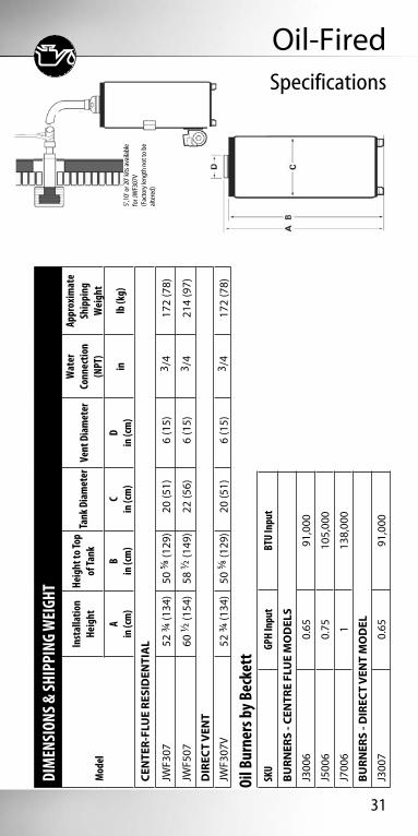
Oil-Fired
Oil burners designed by Beckett• Easy to install• AFG Burner comes with Beckett Clean Cut Fuel Unit. Beckett
R7184 Series 5 Primary Control, self-centering Nozzle Line Electrode. Assembly and one piece Flame Retention Head.
PERFORMANCE
ModelCapacity Standard
Firing Rate InputBTU/hr
Recovery Rate at 100°F/55°C
Temp. Rise
First Hour Rating
Tube Insertion
LengthCombustion
Efficiency
Energy Factor
USG (L) USG/hr USG (L) USG (L) in (cm)
CENTER-FLUE RESIDENTIAL
JWF307 32 (121) 0.65 - 0.75 90,000 84 (318) 110 (416) 4 3/4 (12) 77 – 80% 0.60
JWF507 50 (189) 0.75 106,000 100 (379) 190 (719) 5 3/4 (15) 77 – 80% 0.55
DIRECT VENT**
JWF307V 32 (121) 0.65 90,000 84 (318) 110 (416) 4 3/4 (12) 79 – 81% 0.60
Notes: JWF307, JWF507, meet NAECA and DOE standards. **Direct vent models must use vent kit and burner supplied by John Wood® with pre-purge and post-purge features. Burners are sold separately and warranted by the burner manufacturer.
31
DIM
ENSI
ONS &
SHIP
PING
WEI
GHT
Mod
el
Inst
alla
tion
Heig
htHe
ight
to To
p of
Tank
Tank
Dia
met
erVe
nt D
iam
eter
Wat
er
Conn
ectio
n (N
PT)
Appr
oxim
ate
Ship
ping
W
eigh
tA
in (c
m)
Bin
(cm
)C
in (c
m)
Din
(cm
)in
lb (k
g)
CEN
TER-
FLU
E RE
SID
ENTI
AL
JWF3
0752
3/4 (1
34)
50 5/
8 (12
9)20
(51)
6 (1
5)3 /
417
2 (7
8)
JWF5
0760
1/2 (1
54)
58 1/2
(149
)22
(56)
6 (1
5)3 /
421
4 (9
7)
DIR
ECT
VEN
T
JWF3
07V
52 3/4
(134
)50
5/8 (
129)
20 (5
1)6
(15)
3 /4
172
(78)
Oil-FiredSpecifications
Oil B
urne
rs b
y Bec
kett
SKU
GPH
Inpu
tBT
U In
put
BURN
ERS
- CEN
TRE
FLU
E M
OD
ELS
J300
60.
6591
,000
J500
60.
7510
5,00
0
J700
61
138,
000
BURN
ERS
- DIR
ECT
VEN
T M
OD
EL
J300
70.
6591
,000
5’,1
0’ o
r 20’
kits
ava
ilabl
e fo
r JW
F307
V(F
acto
ry le
ngth
not
to b
eal
tere
d)

32
Storage Booster TanksExclusive, patented innovation.
• Equippedwithanadjustable thermostat, pre-wired and ready for connection to a circulator pump for accurate and automatic temperature control. • Factory-installednipplesfor easy installation.
• 2”ofCFC-freefoaminsulation.
COMBINATIONRETURN & DRAIN VALVE
STORAGEBOOSTER
TANK
T&PVALVE
HOT
HOT
TANKLESS COIL BOILER
COLD
PRESSUREREGULATOR(OPTIONAL)
EXPANSION TANK(OPTIONAL)
CHECK VALVE
CIRCULATORPUMP
SUPPLY (TO BOILERTANKLESS COIL)
JUNCTIONBOX
T&P VALVE
ACCESSDOORS
THERMOSTATRETAINERCOMBINATIONRETURN & DRAINVALVE
THERMOSTATCONTROL
ANODE
HOT OUTLET
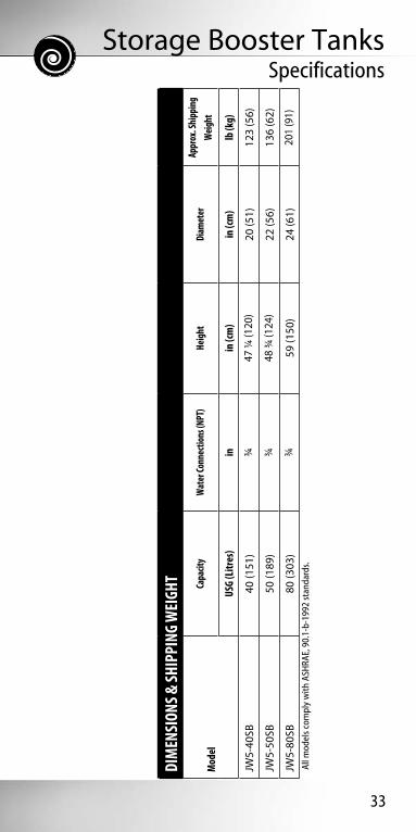
Storage Booster TanksSpecifications
33
DIM
ENSI
ONS &
SHIP
PING
WEI
GHT
Mod
elCa
pacit
y W
ater
Conn
ectio
ns (N
PT)
Heig
htDi
amet
erAp
prox
. Shi
ppin
g W
eight
USG
(Litr
es)
inin
(cm
)in
(cm
)lb
(kg)
JW5-
40SB
40 (1
51)
3/447
1/4 (1
20)
20 (5
1)12
3 (5
6)
JW5-
50SB
50 (1
89)
3/448
3/4 (1
24)
22 (5
6)13
6 (6
2)
JW5-
80SB
80 (3
03)
3/459
(150
)24
(61)
201
(91)
Al
l mod
els c
ompl
y w
ith A
SHRA
E, 9
0.1-
b-19
92 st
anda
rds.

34
• ExclusiveTankSaver® design works to
prolong tank life.
• Factoryinstalleddielectricnipples
for ease of installation.
• T&Pvalveconvenientlylocated
on the side.
• Topaccessjunctionboxfor
convenient electrical hook-up.
• Equippedwithanadjustable
thermostat, pre-wired and ready for
connection to a circulator pump.
C US
FlowTHRU®
Storage tanks specifically designed to complement our series of tankless water heaters.

35
FlowTHRU®
Specifications
DIM
ENSI
ONS &
SHIP
PING
WEI
GHT
Mod
elCa
pacit
y He
ight
Diam
eter
Appr
ox.
Ship
ping
W
eigh
t
USG
(Litr
es)
Ain
. (cm
)B
in. (
cm)
lb. (
kg)
ST-2
019
(67)
25 1/2
(65)
19 (4
9)65
(29)
ST-3
030
(108
)31
1/2 (8
0)22
1/2 (5
7)94
(42)

36
Indirect Water Heaters
•Accurateautomaticsurfacemount thermostat.
•Glasslinedcoilforefficientheattransfer.
•Clean-outportforlimeremovalon 75 gallon models.
•3/4”NPTboilerconnections.
•2”ofCFC-freefoaminsulation.
C US
PERFORMANCE
ModelCapacity Boiler
Output
First Hour Rating
90°F (50°C) Rise/hr
Continuous Flow Coil Length
USG (L) BTU/hr USG (L) USG (L) in (cm)
JW5-30IT/JW10-30IT
30
(110)
40,000 70 (265) 69 (261)
29 (74)60,000 98 (371) 104 (344)
80,000 125 (473) 139 (526)
100,000 152 (575) 173 (655)
JW5-40IT/JW10-40IT
40 (150)
40,000 84 (318) 69 (261)
39 1/2 (100)60,000 111 (420) 104 (394)
80,000 138 (522) 139 (526)
100,000 165 (625) 173 (655)
JW5-75IT/JW10-75IT
75 (300)
40,000 120 (454) 70 (265)
47 1/4 (120)
60,000 148 (560) 105 (397)
80,000 175 (662) 140 (530)
100,000 201 (761) 174 (659)
120,000* 229 (867) 209 (791)
* When the boiler input exceeds 100,000 BTU/hr and if the unit has a factory supplied T&P valve, it must be replaced with one rated for that input.

37
Indirect Water HeatersSpecifications
DIM
ENSI
ONS &
SHIP
PING
WEI
GHT
Mod
el
Heig
ht to
Top o
f Ta
nkHe
ight
to In
let/
Outle
tIn
stalla
tion
Heig
htTa
nk D
iam
eter
Appr
oxim
ate
Ship
ping
Wei
ght
Ain
(cm
)B
in (c
m)
Cin
(cm
)D
in (c
m)
lb (k
g)
JW5-
30IT
/JW
10-3
0IT
32 (8
1)34
(86)
35 (8
9)22
(56)
130
(59)
JW5-
40IT
/JW
10-4
0IT
42 1/2
(108
)44
(112
)45
1/2 (1
16)
22 (5
6)16
0 (7
3)
JW5-
75IT
/JW
10-7
5IT
53 (1
35)
54 (1
37)
56 (1
42)
26 (6
6)27
0 (1
22)
Prin
ted
in C
anad
a
06-
07
I
T121
N20
07 G
SW W
ater
Hea
ting
* Jo
hn W
ood
and
John
Woo
d W
ater
Hea
ters
are
Reg
iste
red
Trad
emar
ks o
f GSW
Wat
er H
eatin
g.
GSW
Wat
er H
eatin
g is
a d
ivis
ion
of A
.O. S
mith
Ent
erpr
ises
Ltd
.
GSW
Lim
ited
War
rant
y:
JW5-30IT/JW
10-30IT
JW5-40IT/JW
10-40IT
JW5-75IT/JW
10-75IT
JW5-30IT/JW
10-30IT
JW5-40IT/JW
10-40IT
JW5-75IT/JW
10-75IT
(USG
/lite
rs)
USG
/lite
rsU
SG/li
ters

38
Range BoilerGlass lined, painted tank.
JWT5140• 40USGallonCapacity/151L.• 14”Diameter.• 1”PipeConnections.• 150PSIworkingpressure.
JWT5140

Tankless


The John Wood powered by Takagi series of condensing tankless water heaters provide endless hot water in any application. The dual heat exchangers are made with high grade material to prevent corrosion and to prolong the life of the heater. These direct vent models combine durability and versatility in an easy-to-install space-saving design.
Features of JWT-320H & JWT-520H Condensing Models:• Built-intemperatureanderrordisplay• Advancedsafetyfeatures• 0.91EnergyFactor• ULCS636PVCorCPVCpipecanbeusedinall applications• Upto16differenttemperaturesettingswithoutaremote
3 2 4 2 0 9 - 0 0 0
P o w e r e d b y
Powered by

40
John Wood® powered by Takagi TanklessHigh efficiency condensing water heaters.
• ENERGYSTAR®qualified.• Advancedsafetyfeatureshelp prevent scalding dangers.• Highefficiencyunitscutwater heating costs and conserve energy.• Highqualityfeaturesand construction.• Applicationflexibility.• CanbeventedusingULCS636 approved PVC or CPVC pipe.• Availablein2inputranges: 13,000-180,000 or 13,000-199,000• Residential models have factory installed power cord and temperature remote control included
3 2 4 2 0 9 - 0 0 0
P o w e r e d b y
See page 42 forFlow Rate Guide

41
John Wood® powered by Takagi Tankless
SpecificationsPE
RFOR
MAN
CE &
DIM
ENSI
ONS
Mod
elAp
plica
tion
Inpu
tBT
U/hr
Max
. Flo
w Ra
te G
PM at
70
°F R
ise
Ener
gy
Facto
rHe
ight
in (c
m)
Wid
thin
(cm
)De
pth
in (c
m)
Appr
oxim
ate
Ship
ping
Wei
ght
lb (k
g)
NA
TURA
L G
AS
JWT-
320H
-NH
eavy
Res
iden
tial
13,0
00 -
180,
000
4.4
0.91
25 5/
8 (65
)18
1/2 (4
7)12
3/8 (
32)
73 (3
3)
JWT-
520H
-NLi
ght C
omm
erci
al /
Hea
vy R
esid
entia
l13
,000
- 19
9,00
04.
70.
9125
5/8 (
65)
18 1/2
(47)
12 3/
8 (32
)73
(33)
PRO
PAN
E
JWT-
320H
-PH
eavy
Res
iden
tial
13,0
00 -
180,
000
4.4
0.91
25 5/
8 (65
)18
1/2 (4
7)12
3/8 (
32)
73 (3
3)
JWT-
520H
-PLi
ght C
omm
erci
al /
Hea
vy R
esid
entia
l13
,000
- 19
9,00
04.
70.
9125
5/8 (
65)
18 1/2
(47)
12 3/
8 (32
)73
(33)

JWT-320H-DV8.08.08.07.46.55.95.55.04.74.44.23.8
JWT-3108.08.07.86.96.25.75.24.84.44.13.93.7
JWT-520H-DV9.09.09.08.17.36.76.15.65.24.94.64.3
JWT-51010.09.38.17.26.55.95.45.04.74.34.13.8
JWT-7109.09.09.08.57.77.06.45.95.55.14.84.5
JWT-91014.514.514.513.512.111.010.19.38.78.17.67.1
Temp Rise (°F)303540455055606570758085
JWT-1106.86.85.75.14.64.23.83.53.33.12.92.7
42
•Highqualitymaterialstoprolong the life of the water heater.•Installationflexibility.•Applicationflexibility.•Residentialmodelsareall ENERGY STAR® qualified.•Advancedsafetyfeatures.•Residentialmodelshavefactory installed power cord and temperature remote control included
John Wood® powered by Takagi Tankless
Residential & Commercial models for any application.
*Note: Refer to following page for specific models and dimensions.
3 2 4 2 0 9 - 0 0 0
P o w e r e d b y
3 2 4 2 0 9 - 0 0 0
P o w e r e d b y
Flowrate GuideTemperature Rise vs. Gallons per minute

43
John Wood® powered by Takagi Tankless
SpecificationsPE
RFOR
MAN
CE &
DIM
ENSI
ONS
Mod
elAp
plica
tion
Inpu
tBT
U/hr
Max
. Flo
w Ra
te G
PM
at 70
°F
Rise
Ener
gy
Facto
rTh
erm
al
Effic
ienc
yHe
ight
in (c
m)
Wid
thin
(cm
)De
pth
in (c
m)
Appr
ox.
Ship
ping
Wei
ght
lb (k
g)
ENER
GY
STAR
NA
TURA
L G
AS
JWT-
110-
NRe
side
ntia
l 19
,500
- 14
0,00
03.
30.
82n/
a20
1/2 (5
2)13
3/4 (3
5)6
3/4 (1
7)33
(15)
YES
JWT-
310-
NRe
side
ntia
l11
,000
- 19
0,00
04.
40.
82n/
a20
1/2 (5
2)13
3/4 (3
5)8
1/2 (2
2)38
(17)
YES
JWT-
510-
NLi
ght C
omm
erci
al/
Hea
vy R
esid
entia
l11
,000
- 19
9,00
04.
70.
82n/
a20
1/2 (5
2)13
3/4 (3
5)8
1/2 (2
2)38
(17)
YES
JWT-
710-
NCo
mm
erci
al24
,000
- 24
0,00
05.
5n/
a82
%23
5/8 (
60)
18 1/2
(47)
8 7/8
(22)
51 (2
3)
JWT-
910-
NCo
mm
erci
al15
,000
- 38
0,00
08.
7n/
a80
%25
1/3 (
64)
24 3/4
(63)
11 3/4
(30)
112
(51)
PRO
PAN
E
JWT-
110-
PRe
side
ntia
l 19
,500
- 14
0,00
03.
30.
83n/
a20
1/2 (5
2)13
3/4 (3
5)6
3/4 (1
7)33
(15)
YES
JWT-
310-
PRe
side
ntia
l11
,000
- 19
0,00
04.
40.
82n/
a20
1/2 (5
2)13
3/4 (3
5)8
1/2 (2
2)38
(17)
YES
JWT-
510-
PLi
ght C
omm
erci
al/
Hea
vy R
esid
entia
l11
,000
- 19
9,00
04.
70.
82n/
a20
1/2 (5
2)13
3/4 (3
5)8
1/2 (2
2)38
(17)
YES
JWT-
710-
PCo
mm
erci
al24
,000
- 24
0,00
05.
5n/
a84
%23
5/8 (
60)
18 1/2
(47)
8 7/8
(22)
51 (2
3)
JWT-
910-
PCo
mm
erci
al15
,000
- 38
0,00
08.
7n/
a82
%25
1/3 (
64)
24 3/4
(63)
11 3/4
(30)
112
(51)

For more information see pages 45 and 46in this book or visit www.johnwoodwaterheaters.com.
High Efficiency Commercial Gas Water Heaters
Designed for outstanding reliability and
excellent thermal efficiency.
• Fullysubmerged,
spiral-shaped
condensing heat
exchanger
• Topmountedcontrols
for easy installation
• Advanced
microprocessor
controls ignition
and thermostat
• Commercialgrade
glass lined tank and
heat exchanger
• Factoryinstalled
T&P valve
3 2 4 2 0 8 - 0 0 0
C O M M E R C I A L

Commercial


44
John Wood® Commercial A proud tradition of leadership.
John Wood Commercial models have been specifically designed for the needs of the professional installer. Our extensive line of commercial gas water heaters is complimented by high efficient models. What’s more, our Commercial electric models can be custom built-to-order to ensure your exact specifications are met. Some of our heaters feature exclusive TankSaver® stainless steel inserts and glass lined tanks for longer life.
3 2 4 2 0 8 - 0 0 0
C O M M E R C I A L
3 2 4 2 0 8 - 0 0 0
C O M M E R C I A L
3 2 4 2 0 7 - 0 0 0
3 2 4 2 0 8 - 0 0 0
C O M M E R C I A L

45
Commercial High Efficient GasUpto96%ThermalEfficiency
• FlexibleventingoptionsusingULCS636 PVC or CPVC.• Poweredanodesthatprovidesuperior tank protection.• Approvedforsanitizingapplications.• Availableinputrates:150,000 BTU, 199,900 BTU, 250,000 BTU, 300,000 BTU and 400,000 BTU.• AvailableinNaturalGasorPropanewith ASME construction (optional on 150/199 and 250,000 BTU models).• Space-savingdesignwithzeroclearance to combustibles for a wide-range of installation applications.• Concentric Vent Kits and Condensate Neutralizer Kits available.
3 2 4 2 0 8 - 0 0 0
C O M M E R C I A L
PERFORMANCE
Model Gas Type Input RateBTU/hr (kW)
Thermal Efficiency
Tank CapacityUSG (L)
Recovery Rate @100°F (56°C)
GPH (LPH)
(A)JWSH100-150 NG/LP 150,000 (44) 95% 100 (379) 173 (654)
(A)JWSH100-199 NG/LP 199,900 (58) 95% 100 (379) 230 (871)
(A)JWSH100-250 NG/LP 250,000 (73) 95% 100 (379) 288
(1090)
AJWSH130-300 NG/LP 300,000 (88) 96% 130 (492) 349
(1322)
AJWSH130-400 NG/LP 399,900 (117) 96% 130 (492) 466
(1763)

46
Commercial High Efficient GasSpecifications
DIM
ENSI
ONS &
SHIP
PING
WEI
GHT
Mod
el
Heig
ht to
Dr
ain
Valv
e(1
50-2
50k
BTU)
Over
all
Diam
eter
Heig
ht to
W
ater
Inle
t /
Drai
n Va
lve
(300
-400
k BT
U)
Heig
ht to
T&
P Va
lve
Inst
alla
tion
Heig
ht
Heig
ht to
Su
pply
Gas
Co
nnec
tion
Heig
ht to
Ve
nt
Conn
ectio
n
Heig
ht
to W
ater
Ou
tlet
Hei
ght t
o Ai
r Int
ake
Appr
ox.
Ship
ping
Wei
ght
(lb/k
g)
Ain
(cm
)B
in (c
m)
Cin
(cm
)D
in (c
m)
Ein
(cm
)F
in (c
m)
Gin
(cm
)H
in (c
m)
Iin
(cm
)ST
DAS
ME
(A)J
WSH
100-
150
3 (8
)27
3/4 (7
1)6
5/16 (
16)
55 1/2
(141
)75
1/2 (1
92)
68 1/2
(174
)11
(28)
63 (1
60)
69 (1
75)
555
(252
)595
(269
)
(A)J
WSH
100-
199
3 (8
)27
3/4 (7
1)6
5/16 (
16)
55 1/2
(141
)75
1/2 (1
92)
68 1/2
(174
)11
(28)
63 (1
60)
69 (1
75)
555
(252
)595
(269
)
(A)J
WSH
100-
250
3 (8
)27
3/4 (7
1)6
5/16 (
16)
55 1/2
(141
)75
1/2 (1
92)
75 1/2
(192
)11
(28)
63 (1
60)
69 (1
75)
555
(252
)595
(269
)
AJW
SH13
0-30
0--
33 1/8
(84)
4 7/8
(12)
50 3/4
(129
)75
1/2 (1
92)
75 1/2
(192
)12
(30.
5)63
(160
)69
(175
)--
885
(408
)
AJW
SH13
0-40
0--
33 1/8
(84)
4 7/8
(12)
50 3/4
(129
)75
1/2 (1
92)
75 1/2
(192
)12
(30.
5)63
(160
)69
(175
)--
885
(408
)

47
Commercial Atmospheric GasHandles a wide-range of applications.
• Inputsavailablerangefrom120,000to 500,000 BTU.• IntermittentElectronicIgnitionsaves energy by eliminating the standing pilot.• Highpressurewaterjetsreducethe sediment at the bottom of the tank to prolong tank life.• Meetsorexceeds80%thermalefficiency.• Inletandoutletportsatthetop,backand front for convenience of installation.• Multipleanodesandglasslinedtankto extend tank life.• ASMEconstructionavailable.• Power vent kits available for these models.
3 2 4 2 0 8 - 0 0 0
C O M M E R C I A L
PERFORMANCE AND RECOVERY RATE GPH / LPH
Model*
Input Rate Tank CapacityThermal
Efficiency
Recovery @100°F (56°C) Temp. RiseGPH (LPH)
BTU/hr (kW/hr) USG (L)
JWSM-71-120 120,000(35) 71 (268) 80% 116 (439)
JWSM-81-154 154,000(45) 81 (307) 80% 149 (564)
JWSM-95-199 199,000(58) 95 (360) 80% 193 (731)
JWSM-76-199 199,000(58) 76 (288) 80% 184 (697)
AJWSM-100-199 199,000(58) 100 (379) 80% 193 (731)
(A)JWSM-65-251 251,000 (73) 65 (246) 80% 243 (921)
AJWSM-100-275 275,000 (80) 100 (379) 80% 267 (1009)
(A)JWSM-65-305 305,000 (89) 65 (246) 80% 296 (1120)
(A)JWSM-65-365 365,000 (107) 65 (246) 80% 349 (1321)
AJWSM-100-390 390,000 (114) 100 (379) 80% 388 (1468)
AJWSM-85-500 500,000 (147) 85 (322) 80% 485 (1835)

48
Commercial Atmospheric GasSpecifications
DIM
ENSI
ONS &
SHIP
PING
WEI
GHT
Mod
el
Inst
alla
tion
Heig
ht
Heig
ht
to G
as
Inle
t
Heig
ht
to To
p of
Ta
nk
Heig
ht to
T&
P
Heig
ht
to F
ront
In
let
Dist
ance
Be
twee
n To
p In
let/
Outle
t
Gas
Valv
e Di
am.
Heig
ht
to Fr
ont
Outle
t
Draf
thoo
d Co
nnec
tion
Diam
.
Tank
Di
amet
erAp
prox
. Sh
ipping
Weig
ht
Ain
(cm
)B
in (c
m)
Cin
(cm
)D
in (c
m)
Ein
(cm
)F
in (c
m)
G inH
in (c
m)
Iin
(cm
)J
in (c
m)
STD.
ASM
Elb
(kg)
lb (k
g)
JWSM
-71-
120
69 3/4
(177
)4
1/4 (1
1)59
1/2 (1
51)
50 3/4
(129
)19
3/4 (5
0)19
(48)
1/251
3/4 (1
32)
5 (1
3)27
3/4 (7
1)40
0 (1
82)
N/A
JWSM
-81-
154
73 (1
85)
4 1/4
(11)
66 1/2
(169
)57
3/4 (1
47)
19 3/4
(50)
19 (4
8)1/2
59 (1
50)
6 (1
5)27
3/4 (7
1)47
0 (2
13)
N/A
JWSM
-95-
199
75 (1
92)
4 1/2
(12)
70 (1
78)
61 5/8
(157
)20
1/2 (5
2)21
(53)
1/262
5/8 (1
59)
6 (1
5)27
3/4 (7
1)60
3 (2
73)
N/A
JWSM
-76-
199
67 1/2
(171
)4
1/2 (1
2)62
(157
)53
5/8 (1
36)
20 1/2
(52)
21 (5
3)1/2
54 5/
8 (13
9)6
(15)
27 3/4
(71)
470
(213
)N
/A
AJW
SM-1
00-1
9972
(183
)4
1/2 (1
2)65
1/8 (1
65)
55 7/8
(142
)19
3/4 (5
0)23
(58)
1/256
3/8 (1
43)
6 (1
5)30
1/4 (7
7)N
/A72
5 (3
29)
(A)J
WSM
-65-
251
75 (1
91)
4 1/2
(12)
65 3/4
(167
)57
1/4 (1
45)
20 (5
1)N
/A1/2
58 3/4
(149
)8
(20)
27 3/4
(71)
750
(341
)86
2 (3
91)
AJW
SM-1
00-2
7572
(183
)4
1/2 (1
2)65
1/8 (1
65)
55 7/8
(142
)19
3/4 (5
0)23
(58)
1/256
3/8 (1
43)
8 (2
0)30
1/4 (7
7)N
/A72
5 (3
29)
(A)J
WSM
-65-
305
75 (1
91)
4 1/2
(12)
65 3/4
(167
)57
1/4 (1
45)
20 (5
1)N
/A1/2
58 3/4
(149
)8
(20)
27 3/4
(71)
750
(341
)86
2 (3
91)
(A)J
WSM
-65-
365
79 1/2
(202
)4
1/2 (1
2)70
1/4 (1
78)
62 1/2
(159
)22
1/2 (5
7)23
(68)
3/463
(160
)8
(20)
27 3/4
(71)
725
(329
)83
3 (3
79)
AJW
SM-1
00-3
9075
1/2 (1
92)
4 1/2
(12)
67 1/2
(171
)58
1/4 (1
48)
26 3/4
(68)
23 (5
8)3/4
59 (1
50)
8 (2
0)30
1/4 (7
7)N
/A87
4 (3
96)
AJW
SM-8
5-50
082
1/4 (2
09)
4 1/2
(12)
73 1/2
(187
)65
1/4 (1
66)
25 1/2
(65)
21 (5
3)1
65 3/4
(167
)8
(20)
27 3/4
(71)
N/A
857
(389
)

49
Commercial ElectricCustom built-to-order.
•MeetsorexceedsASHRAEEfficiency Standards.
•Factoryinstalled11/2” dielectric cold water inlet and hot water outlet nipples for ease of installation.
•2”CFC-freefoaminsulation.
•Convenientlylocatedhandholecleanout.
•FactoryinstalledT&Pandbrassdrainvalve.
3 2 4 2 0 8 - 0 0 0
C O M M E R C I A L
CONFIGURING YOUR MODEL1. Select thermostat
Note: Immersion thermostat is required for 180°F (82°C) sanitizing applications.
Surface (JW-ES) or Immersion (JW-EI)
2. Select capacity required (USG)49 / JW-E(S/I)-5074 / JW-E(S/I)-80
111 / JW-E(S/I)-119
3. Select input (kW) 6-54
4. Select voltage (600 Volt available in 3 Ph only) 208, 240 or 600
5. Select phase 1 or 3
Example:JW-EI-80-45-240-3 is an 74 U.S. Gallon, 45 kW, 240 volt, 3 phase model with an Immersion Thermostat.

50
Commercial ElectricSpecifications
DIM
ENSI
ONS &
SHIP
PING
WEI
GHT
Mod
el
Inst
alla
tion
Heig
htHe
ight
to
Top
of Ta
nkHe
ight
to
T&P
Valv
eHe
ight
to
Clea
nout
Heig
ht
to D
rain
Va
lve
Heig
ht
to Co
ld
Wat
er
Inle
t
Heig
ht to
Bo
ttom
of
Pane
l
Heig
ht
to To
p of
Pa
nel
Diam
eter
Pane
l De
pth
Pane
l W
idth
Appr
ox.
Ship
ping
W
eigh
t
Ain
(cm
)B
in (c
m)
Cin
(cm
)D
in (c
m)
Ein
(cm
)F
in (c
m)
Gin
(cm
)H
in (c
m)
Iin
(cm
)J
in (c
m)
Kin
(cm
)lb
(kg)
JW-E
(S/I)
-50
53 (1
35)
51 1/2
(131
)41
1/4 (1
05)
7 1/4
(18)
5 1/4
(13)
6 1/4
(16)
6 1/2
(17)
49 1/2
(126
)22
1/4 (5
7)6
1/2 (1
7)17
1/2 (4
4)27
7 (1
26)
JW-E
(S/I)
-80
63 1/2
(161
)61
1/2 (1
56)
51 3/4
(131
)7
1/4 (1
8)5
1/4 (1
3)6
1/4 (1
6)6
1/2 (1
7)57
(145
)24
1/4 (6
2)6
1/2 (1
7)17
1/2 (4
4)33
8 (1
53)
JW-E
(S/I)
-119
66 3/4
(170
)64
1/2 (1
64)
53 3/4
(137
)7
(18)
5 (1
3)6
(15)
6 1/2
(17)
57 1/4
(146
)28
1/2 (7
2)6
1/2 (1
7)17
1/2 (4
4)45
7 (2
07)

51
Commercial Oil-FiredHigh output, high efficiency.
• Multi-fluedesignforfastrecovery.
• Equippedwithmultipleanoderodsfor long life.
• FactoryinstalledT&Panddrainvalve.
• Universalmountingdesignsuits most burners.
• Includesblockedfluesafetyswitch in accordance with CSA B140.0-03.
• TankSaver® technology.
3 2 4 2 0 8 - 0 0 0
C O M M E R C I A L
PERFORMANCE
ModelCapacity Standard
Firing Rate InputBTU/hr
Recovery Rate at 100°F/55°C
Temp. Rise
First Hour Rating
Tube Insertion
LengthCombustion
EfficiencyUSG (L) USG/hr USG (L) USG (L) in (cm)
CENTER-FLUE COMMERCIAL
JWF657 63 (238) 1.00 – 1.25 138,500 129 (488) 163 (617) 7 3/4 (20) 82 – 86%
Notes: JWF657 meets ASHRAE/IES 90.1b-1992 energy standards.
See Pages 28-29 for more information about Beckett
burners

52
Commercial Oil-FiredSpecifications
DIM
ENSI
ONS &
SHIP
PING
WEI
GHT
Mod
el
Inst
alla
tion
Heig
htHe
ight
to To
p of
Tank
Tank
Dia
met
erVe
nt D
iam
eter
Wat
er
Conn
ectio
n (N
PT)
Appr
oxim
ate
Ship
ping
W
eigh
tA
in (c
m)
Bin
(cm
)C
in (c
m)
Din
(cm
)in
lb (k
g)
CEN
TER-
FLU
E CO
MM
ERCI
AL
JWF6
5768
3/4 (1
75)
65 3/
8 (16
6)26
(66)
6 (1
5)1
379
(172
)

Commercial Storage TanksAvailable in 80 and 119 USG models.
53
• Equippedwithmultipleanoderods for long life.
• Convenientlylocatedhandholecleanout.
• Factoryinstalled2”dielectricnipples and brass drain valve on insulated models.
• 2”CFC-freefoaminsulationon CST-119 and CST-80.
• Frontinletandoutletforrecirculation.
3 2 4 2 0 8 - 0 0 0
C O M M E R C I A L

54
Commercial Storage TanksSpecifications
A
CD
E F
G
B
H
DIM
ENSI
ONS &
SHIP
PING
WEI
GHT
Mod
elCa
pacit
y He
ight
Heig
ht to
T&
P va
lveUp
per
conn
ectio
nLo
wer
co
nnec
tion
Hand
hole
cle
anou
tDr
ain
Valve
Aqua
stat
op
enin
gDi
amet
erAp
prox
. Sh
ippi
ng
Wei
ght
USG
(L)
A in
(cm
)B
in (c
m)
C in
(cm
)D
in (c
m)
E in
(cm
)F
in (c
m)
G in
(cm
)H
in (c
m)
lb (k
g)
CST-
119
119
(454
)65
3 /8 (
166)
55 3 /
8 (14
1)15
1 /5 (3
9)10
1 /2 (2
7)8
1 /2 (2
2)8
3 /4 (2
3)15
1 /2 (3
9)28
(71)
342
(155
)
CE-1
19(B
are
Tank
)11
9 (4
54)
61 1 /2
(156
)53
1 /8 (1
35)
13 3 /
4 (35
)8
3 /4 (2
3)6
1 /2 (1
7)4
3 /4 (1
2)13
3 /4 (
35)
24 1 /2
(62)
222
(110
)
CST-
80 8
0 (2
70)
60 1 /4
(153
)52
1 /4 (1
33)
14 (3
6)9
(23)
7 (1
8)5
(13)
14 (3
6)24
(61)
195
(88)
CE-8
0(B
are
Tank
)80
(270
)58
(147
)51
1 /2 (
131)
13 3 /
8 (34
)8
1 /2 (2
2)6
1 /8 (1
6)4
1 /2 (1
1)13
1 /8 (3
4)20
1 /2 (5
2)13
4 (6
1)

55
Light Duty Commercial GasThe right atmospheric vent for lower demand commercial applications.
‘Series 10’ Model:• Thermopiledesignprovidesrobust pilots to withstand down drafts and environmental conditions.• LEDindicatorlightletsyouknowwhen pilot is in operation and provides diagnostic capabilities.• Easytemperatureadjustment.
All Light-Duty Commercial Atmospheric Models:• Dependablethree-legdesignfor better leveling.• Galvanizedsteelbottomforlonglife.• CFC-freefoaminsulation.• 180˚Fthermostattomeetcommercial water requirements and sanitizing applications.
JW3-75-3NC Model Shown
3 2 4 2 0 8 - 0 0 0
C O M M E R C I A L
PERFORMANCE
ModelCapacity Maximum
Certified Altitude InputRecovery at 100°F/55°C
Rise
First Hour Rating Energy
Factor
USG (L) ft (m) BTU/hr USG (L) USG (L)
NATURAL GAS
JW6058NA-FV-02 60 (227) 2,000 (609) 58,000 53 (200) 104 (394) 0.56
JW6058NA-FV-04 60 (227) 4,500 (1,371) 52,200 53 (200) 98 (371) 0.56
JW6054NA Series 10 60 (227) 5,400 (1,645) 54,000 49 (186) 104 (394) 0.54
JW3-75-3NC-02 75 (284) 2,000 (609) 76,000 67 (252) 151 (572) n/a
JW3-75-3NC-04 75 (284) 4,500 (1,371) 76,000 67 (252) 136 (515) n/a
PROPANE
JW6058PC-FV-180 60 (227) 2,000 (609) 58,000 53 (200) 104 (394) 0.56
3G6058PC-FV-06 60 (227) 4,500 (1,371) 52,200 53 (200) 98 (371) 0.56
JW3-753-PC-05 75 (284) 2,000 (609) 76,000 67 (252) 151 (572) n/a
JW3-753-PC-06 75 (284) 4,500 (1,371) 68,400 67 (252) 136 (515) n/a

56
Light Duty Commercial GasSpecifications
DIM
ENSI
ONS &
SHIP
PING
WEI
GHT
Mod
elIn
stalla
tion H
eight
Tank
Diam
eter
Vent
Diam
eter
Appr
ox. S
hipp
ing
Weig
ht
A in
(cm
)B
in (c
m)
C inlb
(kg)
NA
TURA
L G
AS
JW60
58N
A-F
V63
(160
)24
5/8 (
63)
418
1 (8
2)
JW60
54N
A S
erie
s 10
63 (1
60)
24 5/
8 (63
)4
176
(80)
JW3-
75-3
NC
65 (1
67)
26 (6
6)4
272
(123
)
PRO
PAN
E
JW60
58PC
-FV
63 (1
60)
24 5/
8 (63
)4
181
(82)
3G60
58PC
-FV-
0663
(160
)24
5/8 (
63)
418
1 (8
2)
JW3-
753-
PC65
3/4 (
167)
26 (6
6)4
272
(123
)
BA

57
Light Duty Commercial ElectricThe right fit for lower demand commercial applications.
• Automatictemperaturecontrol.
• CFC-freefoaminsulation.
• Heavydutycontactorsdesigned to handle all anticipated loads.
• Overtemperatureprotection.
• Wide-rangeofelectricalknockouts.
45°
90°
14 1/2"(370mm)
TWOCOMBINED
1 1/2" & 2"KNOCKOUTS
ON TOP OFJUNCTION
BOX ALL WATER CONNECTIONS - 1" N.P.T.
TWOCOMBINED
1 1/2" & 2"KNOCKOUTS
ON OPPOSITESIDE OF
JUNCTIONBOX
24 1/4"(615mm)
71 3/8"(1813mm)
8 1/4"(210mm)
6 1/2"(165mm)
4"(100mm)
28 1/4" O.D. (715mm)
DRAINOUTLET & DRAIN AREINTERCHANGEABLE
OUTLET
3 2 4 2 0 8 - 0 0 0
C O M M E R C I A L

58
Light Duty Commercial ElectricSpecifications
PERF
ORM
ANCE
Mod
el
Capa
city
Max
. No.
of
El
emen
tsPh
ase
120 V
olts
Max
. kW
208 V
olts
Max
. kW
240 V
olts
Max
. kW
480 V
olts
Max
. kW
600 V
olts
Max
. kW
USG
Litre
sPe
r Ele
men
tTo
tal
Conn
ected
Per
Elem
ent
Total
Co
nnec
tedPe
r Ele
men
tTo
tal
Conn
ected
Per
Elem
ent
Total
Co
nnec
tedPe
r Ele
men
tTo
tal
Conn
ected
JWE1
202A
108
409
2Si
ngle
36
510
612
JWE1
204A
108
409
4Si
ngle
312
520
624
JWE1
206A
108
409
6Si
ngle
318
530
636
JWE1
206B
108
409
6Th
ree
530
636
JWE1
206C
108
409
6Th
ree
636
636
JWE1
209A
108
409
9Si
ngle
327
545
654
JWE1
209B
108
409
9Th
ree
545
654
JWE1
209C
108
409
9Th
ree
654
654

59
Polaris® CommercialThe quiet and efficient way to heat water.
• Highgradestainlesssteeltank with brass connections for years of dependable service – no anode required.• Submergedcombustionchamber withspiralfluefor95-96%thermal efficiency and ultra-low standby heat loss.• Wovenmetalfibreburnerof refractory steel resists corrosion, produces low NOx emissions and is resistant to thermal and mechanical shocks. • Uniformcombustionprovides excellent heat transfer.• Plug-and-playtechnologywithno special adjustments at initial startup including no adjustments or de-rating for high altitude installations.
PERFORMANCE
ModelCapacity Input Recovery @
100oF Rise Thermal Efficiency
USG (L) BTU/hr GPH (LPH)
NATURAL GAS
PC130-34-2NV 34 (129) 130,000 151 (578) 96%
PC130-50-2NV 50 (189) 130,000 150 (576) 95%
PC175-50-3NV 50 (189) 175,000 204 (779) 95%
PC199-50-3NV 50 (189) 199,000 232 (885) 95%
PROPANE
PC130-34-2PV 34 (129) 130,000 151 (578) 96%
PC130-50-2PV 50 (189) 130,000 150 (576) 95%
PC175-50-3PV 50 (189) 175,000 204 (779) 95%
PC199-50-3PV 50 (189) 199,000 232 (885) 95%

60
Polaris® CommercialSpecifications
DIM
ENSI
ONS &
SHIP
PING
WEI
GHT
Mod
elHe
ight
Heig
htto
T&P
Valve
Cold
W
ater
Inle
t*
Gas
Inle
t
Heat
ing
Syste
m In
let*
Heat
ing
Syste
m O
utle
t*Di
amet
erVe
ntDi
am.
Appr
ox.
Ship
ping
W
eigh
t
Ain
(cm
)B
in (
cm)
Cin
(cm
)D
in (c
m)
Ein
(cm
)F
in (c
m)
Gin
(cm
)in
lb (k
g)
NA
TURA
L G
AS
PC13
0-34
-2N
V48
1/2 (1
23)
41 (1
04)
15 3/4
(40)
6 1/8
(16)
15 3/4
(40)
40 1/2
(103
)22
(56)
2-3
150
(68)
PC13
0-50
-2N
V62
1/2 (1
59)
55 (1
40)
15 3/4
(40)
6 1/8
(16)
15 3/4
(40)
54 1/2
(138
)22
(56)
2-3
170
(77)
PC17
5-50
-3N
V62
3/4 (1
62)
56 1/4
(143
)15
3/4 (4
0)6
1/8 (1
6)15
3/4 (4
0)55
3/4 (1
42)
22 (5
6)3
180
(82)
PC19
9-50
-3N
V62
3/4 (1
62)
56 1/4
(143
)15
3/4 (4
0)6
1/8 (1
6)15
3/4 (4
0)55
3/4 (1
42)
22 (5
6)3
180
(82)
PRO
PAN
E
PC13
0-34
-2PV
48 1/2
(123
)41
(104
)15
3/4 (4
0)6
1/8 (1
6)15
3/4 (4
0)40
1/2 (1
03)
22 (5
6)2-
315
0 (6
8)
PC13
0-50
-2PV
62 1/2
(159
)55
(140
)15
3/4 (4
0)6
1/8 (1
6)15
3/4 (4
0)54
1/2 (1
38)
22 (5
6)2-
317
0 (7
7)
PC17
5-50
-3PV
62 3/4
(162
)56
1/4 (1
43)
15 3/4
(40)
6 1/8
(16)
15 3/4
(40)
55 3/4
(142
)22
(56)
318
0 (8
2)
PC19
9-50
-3PV
62 3/4
(162
)56
1/4 (1
43)
15 3/4
(40)
6 1/8
(16)
15 3/4
(40)
55 3/4
(142
)22
(56)
318
0 (8
2)
*1
” NPT
wat
er c
onne
ctio
ns.
AB
C
D
E
F
G
34-5
0 U
SG

For more information about our wide-range of products or gain access to the online:
• WarrantyValidation-nowsubmitclaims online for quicker and more convenient processing times.• PartsCatalogue-lookforpartsbymodel or serial number in our comprehensive catalogue.• ContractorLocator-searchforcontractors in your region
Looking for a part?Need a contractor?
Submitting a warranty claim?
www.johnwoodwaterheaters.com

Appendices


61
AppendicesCross-Over Matrix
JW60
58
60
58
JW60
58
60
58
G60-
50
60
50
BT-6
5 65
50
50
T-65
-3N
48
65
JW3-
75-3
75
76
JW
752
75
75
G75-
75
75
75
BT-8
0 74
74
75
T-80
E-3N
75
80
JWSM
71-1
20
71
120
JWSC
75-1
25
75
125
G75-
125
75
125
BTRC
-120
71
12
0 D-
75T-
125-
3N
75
125
UG73
-125
N 73
12
5
JWSM
81-1
54
81
154
JW80
-160
80
16
0 G8
2-15
6 82
15
6 BT
RC-1
54
81
154
D-75
T-16
0-3N
75
16
0 UG
73-1
50N
73
150
JWSM
76-1
99
76
199
JWSC
80-1
99
80
199
G76-
200
76
200
BTRC
-199
76
19
9 D-
80T-
199-
3N
80
199
UG73
-200
N 73
20
0
JWSM
76-1
99
76
199
JWSC
80-1
99
80
199
G37-
200
37
199
BTRC
-199
76
19
9 D-
80T-
199-
3N
80
199
UG73
-200
N 73
20
0
JWSM
65-2
51
65
251
JWSC
80-2
50
80
250
G72-
250
72
250
BTRC
-251
65
25
1 D-
80T-
250-
3N
80
250
UG65
-250
N 65
25
0
JWSM
95-1
99
95
199
JWSC
100-
199
100
199
G91-
200
91
199
BTRC
-197
95
19
9 D-
100T
-199
-3N
100
199
JWSM
76-1
99
76
199
JWSC
100-
199
100
199
G100
-200
10
0 19
9 BT
RC-1
99
76
199
D-10
0L-1
99-3
N
100
199
JWSC
100-
270
100
270
AJW
SC10
0-27
0 10
0 27
0 G1
00-2
70
100
270
BTRC
-275
A 10
0 27
5 D-
100L
-270
-3N
100
270
JWSM
65-3
05
65
305
JWSC
75-3
00
75
300
G72-
300
72
300
BTRC
-305
65
30
5 D-
75T-
300-
3N
75
300
UG65
-300
N 65
30
0
JWSM
65-3
65
65
365
JWSC
75-3
60
75
360
G65-
360
65
360
BTRC
-365
65
36
5 D-
65T-
370-
3N
65
370
UG65
-360
N 65
36
0
JWSM
85-5
00
75
500
JWSC
75-5
05
75
505
G85-
400
85
399
BTRC
-500
75
50
0 D-
80L-
505-
3N
80
505
AJW
SM10
0-19
9 10
0 19
9 AJ
WSC
100-
199
100
199
G100
-200
A 10
0 19
9 BT
RC-2
00A
100
199
AJW
SM65
-251
65
25
1 AJ
WSC
80-2
50
80
250
G72-
250A
72
25
0 BT
RC-2
51A
65
251
D-80
T-25
0-3N
A 80
25
0
AJW
SM10
0-27
5 10
0 27
5 AJ
WSC
100-
270
100
270
G100
-250
A 10
0 25
0 BT
RC-2
50A
100
250
D-10
0T-2
50-3
NA
98
250
AJW
SM10
0-27
5 10
0 27
5 AJ
WSC
100-
270
100
270
G100
-270
A 10
0 27
0 BT
RC-2
75A
100
275
D-10
0L-2
70-3
NA
100
270
AJW
SM65
-305
65
30
5 AJ
WSC
75-3
00
75
300
G72-
300A
72
30
0 BT
RC-3
05A
65
305
D-75
T-30
0-3N
A 75
30
0
AJW
SM65
-365
85
36
5 AJ
WSC
75-3
60
75
360
G65-
360A
65
36
0 BT
RC-3
65A
85
365
D-65
T-37
0-3N
A 65
37
0
AJW
SM10
0-39
9 10
0 39
9 AJ
WSC
75-3
99
75
399
G85-
400A
85
39
9 BT
RC-4
00A
100
399
D-80
L-39
9-3N
A
80
399
AJW
SM85
-500
85
50
0 AJ
WSC
75-5
05
75
505
G85-
400A
85
39
9 BT
RC-5
00A
85
500
D-80
L-50
5-3N
A 80
50
5
MTBU
Gal. Cap.
John
Woo
d Co
mm
ercia
lM
odel
#Ol
d Jo
hn W
ood
Mod
el #
Rhee
m
Mod
el #
New
AOS
M
odel
#Br
adfo
rd W
hite
M
odel
#Gi
ant
MTBU
Gal. Cap.
MTBU
Gal. Cap.
MTBU
Gal. Cap.
MTBU
Gal. Cap.
MTBU
Gal. Cap.
CO
MM
ERC
IAL
GA
S C
ROSS
REF
EREN
CE
CH
ART

62
AppendicesSizing Guide
Commercial Electric Water Heater Quick Sizing Guide
# of Units kW
1-3 27
4-7 54
8-10 2-36
11-17 2-54
18-25 3-54
26-32 4-54
33-40 5-54
41-48 6-54
49-64 8-54
65-80 10-54
MOTELS AND HOTELS*
# of Units kW
1-7 18
8-15 36
16-20 45
21-32 2-36
33-55 3-45
56-70 3-54
APARTMENT BUILDINGS* # of Stations kW
1-3 9
4-9 30
10-15 54
16-21 2-36
22-35 3-54
BEAUTY/BARBER SHOPS
# of Units kW
1-3 27
4-7 54
8-10 2-36
11-17 2-54
18-25 3-54
26-32 4-54
33-40 5-54
41-48 6-54
49-64 8-54
65-80 10-54
COIN OPERATED LAUNDRIES
*Sizing based on 2-3 gallon/minute shower heads and systems with circulation returns. For larger buildings consult the factory.

63
AppendicesSizing Guide
Commercial Gas Water Heater Quick Sizing Guide
# of Units Model
1-3 1-JWSM71-120
4-10 1-JWSM95-199
11-17 2-JWSM65-251
18-25 2-JWSM65-365
26-32 3-JWSM65-305
33-40 3-JWSM65-365
41-46 4-JWSM65-305
47-64 5-JWSC75-399
65-80 6-JWSC75-399
MOTELS AND HOTELS* # of Units Model
1-4 1-JW3-75-3
5-7 1-JWSM76-199
8-9 1-JWSC75-250
10-12 1-JWSM65-305
13-16 1-JWSC75-399
17-20 2-JWSC75-250
21-25 2-JWSC75-399
COIN OPERATED LAUNDRIES
# of Units Model
1-7 1-JWSM71-120
8-15 1-JWSM95-199
16-20 1-JWSM65-365
21-32 1-JWSC75-399
33-55 2-JWSM65-365
56-70 2-JWSC75-399
APARTMENT BUILDINGS* # of Stations Model
1-3 1-JW6058
4-9 1-JWSM71-120
10-15 1-JWSM65-251
16-21 1-JWSM65-305
22-35 2-JWSM65-305
BEAUTY/BARBER SHOPS
*Sizing based on 2-3 gallon/minute shower heads and systems with circulation returns. For larger buildings consult the factory.

64
AppendicesReference Calculations and Conversions for Electricity
Ohm’s Law
Ohm’s Law defines the relationships between (P) power, (E) voltage, (I) current, and (R) resistance. One ohm is the resistance value through which one volt will maintain a current of one ampere.
(I) Current is what flows on a wire or conductor like water flowing down a river. Current flows from points of high voltage to points of low voltage on the surface of a conductor. Current is measured in (A) amperes or amps.
(E) Voltage is the difference in electrical potential between two points in a circuit. It’s the push or pressure behind current flow through a circuit, and is measured in (V) volts.
(R) Resistance determines how much current will flow through a component. Resistors are used to control voltage and current levels. A very high resistance allows a small amount of current to flow. A very low resistance allows a large amount of current to flow. Resistance is measured in ohms.
(P) Power is the amount of current times the voltage level at a given point measured in wattage or watts.

65
AppendicesReference Guide for Water Heating
One US gallon of fresh water weighs 8.333 lb.
Waterexpands4.34%heatedfrom40o to 212o F.
1 BTU = Amount of heat required to raise the temperature of 1 lb. of water 1o F.
Recovery GPH = KW x 3412(Electric) 8.33 x ∆T
Recovery GPH = Input x Efficiency(Gas) 8.33 x ∆T
Req. BTU Input = Water Heater Capacity x 8.33 x ∆T %Efficiency
First Hour Draw (FHD)FHD=(Storagex%Efficiency)+Recovery
%ofhotandcoldwaterneededtobemixedtoobtainadesiredtemperature
Hot water percentage = M-C H-C
Cold water percentage = H-M H-C
Water C = Cold Water Temperature H = Hot Water Temperature M = Mixed Water Temperature
%Efficiency= GPHx8.33xTemp.Rise BTU/Hr. Input

66
AppendicesReference Guide for Water Heating
BTU/Output = GPH x 8.33 lbs./Gal. x Temp. Rise
BTU/Input = GPH x 8.33 x Temp. Rise %Efficiency
KW = GPH x 8.33 x Temp. Rise 3413
Temperatures
To convert from degrees Centigrade (C) to degrees Fahrenheit (F) multiply the number of degrees C by 9/5 (or 1.8) and add 32.
To convert from degrees Fahrenheit (F) to degrees Centigrade (C) first subtract 32 from the number of degrees F then multiply the remainder by 5/9 (or 0.556).
Gas/Oil
Gas BTU 1 lb. of Butane = 21,300 1 Gal. of Butane = 102,600 1 Cu. Ft. of Butane = 3,260 1 Cu. Ft. of Manufactured = 530 1 Cu. Ft. of Mixed = 850 1 Cu. Ft. of Natural = 1,075 1 lb. of Propane = 21,600 1 Gal. of Propane = 91,700 1 Cu. Ft. of Propane = 2,570

67
AppendicesReference Guide for Water Heating
Oil vs. Electric vs. Propane vs. Natural Gas
Oil 1 litre = 36,515 BTUs* Example Price = 60.0¢/litre Electric 1 Kilowatt Hour = 3,413 BTUs* Example Price = 10.1¢/KW (kilowatt) Propane 1 litre = 24,197 BTUs* Example Price = 63.0¢/litre
Natural Gas 1 M3 35,310 BTUs* Example Price = 44.0¢/M3 (cubic metre)** Formula BTUs per Unit x Efficiency Cost per Unit Example: Propane=24,197x92%=35335BTUsper$1.00 0.63 GST is extra on all prices. * Information supplied by The Ontario Ministry of Energy.** This price reflects delivery charge and monthly administration charge to service your account.
Formulas and Facts
• 1gallonofwaterweighs8.33lbs.
• 1gallonofwaterhasavolumeof231cubicinches
• 1cubicfootofwaterweighs62.38lbs.andcontains7.48gallons
of water
• 100feetof3/4”copperpipecontains2.5gallonsofwater;1”pipe contains 4.3 gallons
• 8.33BTUwillraise1gallonofwater1o Fat100%efficiency (electricity)

68
AppendicesReference Guide for Water Heating
• 11BTUsarerequiredtoraise1gallonofwater1o Fat70%efficiency (gas)
• 3,412BTUsequal1kilowatthour(KW)
• 1KWwillraise410gallonsofwater1o Fat100%efficiency
• 1BTUx0.293=watts
•1KW=1000watts
• 2.42wattsarerequiredtoraise1gallonofwater1o F
1 KW will raise 10.25 gallons of water 40o Fat100%efficiency
1 KW will raise 6.8 gallons of water 60o Fat100%efficiency
1 KW will raise 5.1 gallons of water 80o Fat100%efficiency
1 KW will raise 4.1 gallons of water 100o Fat100%efficiency
Formula for mixing hot water
M-C H-C
WhereM=mixedwatertemperature;C=coldwatertemperature;H = hot water temperature
For example: How much of a shower is hot water and how much is cold water?
My shower temperature is 105o F, my water heater thermostat is set on 120o F and the cold water inlet temperature is 50o F. 105 – 50 = 55 120 – 50 = 70
This formula for mixing hot water is important when explaining a NOT ENOUGH HOT WATER trouble call and the water heater is functioning properly.
=79%oftheshoweris120o hot water
= Percent of hot water required to produce desired mixed temperature

69
AppendicesReference Guide for Water Heating
= 23 gallons per hour
= 80o temp
= 45 gallons per hour
= 80o temp
ELECTRIC
Energy Costs:
KW x fuel costs = energy costs
100x0.05=$5.00
To obtain gallons per hour
(GPH) recovery
WATTS
2.42 x (temp rise o F)
I have a 30-gallon electric heater,
non-simultaneous operation, 4,500
watt elements. What is the recovery
GPH if my cold water is 40o F and my
thermostat is set to 120o F?
4,500
2.42 x 80
Temperature Rise (o F)
WATTS
2.42 x GPH
I have a 30-gallon electric heater,
non-simultaneous operation,
4,500 watt elements. What is the
maximum temperature rise if the
heater can recover 23 gallons per
hour?
4,500
2.42 x 23 rise
GAS
Energy Costs:
Cubic feet x fuel costs = energy costs
100x0.75=$7.50
To obtain gallons per hour
(GPH) recovery
HOURLY INPUT (BTUs)
11.0 x (temp rise o F)
I have a 30-gallon gas heater,
rated at 40,000 BTUs. What is the
recovery GPH if my cold water is 40o F
and my thermostat is set to 120o F?
40,000
11.0 x 80
Temperature Rise (o F)
HOURLY INPUT (BTUs)
11.0 x GPH
I have a 30-gallon gas heater,
rated at 40,000 BTUs. What is the
maximum temperature rise if the
heater can recover 45 gallons per
hour?
40,000
11.0 x 45 rise

70
AppendicesReference Guide for Water Heating
Oil BTU 1 Gal. #1 Fuel = 136,000 1 Gal. #2 Fuel = 138,500 1 Gal. #3 Fuel = 141,000 1 Gal. #5 Fuel = 148,500 1 Gal. #6 Fuel = 152,000
1 lb. of Gas = 28” Water Column 1 lb. of Gas = 16 oz. 100 Cu. Ft. = 1 therm.
Conversions
Multiply By To Obtain BTU/HR 0.293 W Ft. 0.3048 m Ft./min., fpm 0.00508 m/s Ft.2 0.0929 m2
Ft.3 0.0283 m3
Gallon (U.S. 231 in3) 3.79 L Gallon 0.00379 m3
Horsepower (boiler) 9.81 KW Inch 25.4 mm Mile 1.61 km Pound lb. (mass) 0.454 kg Psi 6.89 kPa

71
AppendicesExclusive Designs, Built-to-Last
John Wood Water Heaters are designed and built with features to ensure maximum quality, safety and reliability. Our heaters are thoroughly factory tested, field-proven and meet or exceed industry standards. TankSaver®
The exclusive TankSaver® design prolongs tank life. TankSaver® impedes corrosion by guarding metal tank openings from exposure to water and keeping them watertight. The durable construction virtually eliminates rust. American Society of Mechanical Engineers (ASME) In June 2004, GSW Water Heating became authorized by ASME to build tanks in accordance with the ASME Boiler and Pressure Vessel Code. ASHRAE Efficiency Standard 90.1 1999 John Wood commercial water heaters meet the ASHRAE Efficiency Standard 90.1 1999. The burner efficiency of these units is over 80%. Certified Hydrostatic Tests Design test pressure - 300 psi. Maximum working pressure - 150 psi. NRCan Standard All John Wood residential water heaters meet or exceed NRCan energy efficiency standards.
Coast-to-Coast Service & Support
In order to bring you unsurpassed quality and reliability after you’ve purchased a John Wood product, we’ve created a number of service and support resources to help take you through installation and beyond. Operating hours are 8:00 a.m. to 6:00 p.m. EST for our Technical Support call centre (1-888-479-8324), which is staffed by technical experts who provide in-depth product support and troubleshooting advice. We offer a wide-range of hands-on training programs from basic refresher courses to product-specific programs. Our spare parts inventory carries a comprehensive supply of parts to help make repairs fast and easy.

72
Notes

73
Notes

74
Notes

Type
In
ner T
ank
Pa
rts
Resi
dent
ial W
ater
Hea
ters
- G
as a
nd E
lect
ric
8 ye
ars
6 ye
ars
Spac
eSav
er® M
odel
s (e
xcep
t SS0
25 –
5 y
ears
) 6
year
s 1
year
Indi
rect
s 5
year
s 1
year
Stor
age
Boos
ters
5
year
s 1
year
Resi
dent
ial O
il Fi
red*
6
year
s 1
year
(exc
lude
s bu
rner
)Co
mm
erci
al W
ater
Hea
ters
3
year
s 1
year
Insu
late
d Co
mm
erci
al S
tora
ge T
anks
5
year
s 1
year
Rang
e Bo
ilers
1
year
N
/ABa
re C
omm
erci
al S
tora
ge T
anks
1
year
N
/ACo
mm
erci
al P
olar
is®
3 ye
ars
1 ye
arRe
side
ntia
l Pol
aris
® 10
yea
rs
1 ye
arTa
nkle
ss R
esid
entia
l 12
yea
rs
5 ye
ars
Tank
less
Com
mer
cial
5
year
s 5
year
sEn
viro
sens
eTM
Mod
els
6 ye
ars
6 ye
ars
*Oil
bu
rner
s ar
e g
uar
ante
ed b
y b
urn
er m
anu
fact
ure
r.
War
rant
y1.
War
rant
y te
rms
are
set o
ut o
n th
e w
arra
nty
cert
ifica
te e
nclo
sed
with
eac
h Jo
hn W
ood
wat
er h
eate
r. 2
. War
rant
y cr
edits
are
is
sued
onl
y w
here
a Jo
hn W
ood
wat
er h
eate
r is
used
as
the
repl
acem
ent.

ProductCatalogueE l e c t r i c • G a s • O i l • T a n k l e s s
R e s i d e n t i a l & C o m m e r c i a l
©2012 GSW Water Heating.Printed in Canada 03/12 J309C
Joh
n W
oo
d® Pro
du
ct Catalo
gu
e
Head office:John Wood® 599 Hill Street WestFergus, ON N1M 2X1Tel: 1-888-599-2837Fax: 1-519-787-5500
Technical Support and Warranty:Tel: 1-888-479-8324
Sales/Customer Service:Tel: 1-888-599-2837
06/12