residential kitchen/bath/laundry remodel checklist for a
TRANSCRIPT

July 12, 2020
1 of 13
This Kitchen & Bath Remodel Checklist is based on St. Louis County’s (SLCO) policies and construction codes as amended and adopted by ordinance. See the Codes list below. This checklist is not a substitute for those codes and ordinances, but serves as a guide to reading them. More information and explanation is provided in the St. Louis County Single-Family Dwelling Design Checklist, and in commentaries and interpretations published by St. Louis County and acknowledged code organizations.
List of Applicable Codes and Ordinances: 2015 International Residential Code (IRC) & Ordinance #27,654-Ch.1116 (“R” “G”, “N”, and “M”
references and Appendix K - Sound Transmission).
2015 International Building Code (IBC) & Ordinance #27,654-Ch.1116\5 (“B” references). 2015 International Property Maintenance Code (IPMC) & Ord. #27,617-Ch.1110 (“PM” refs.).
2014 National Electrical Code (NEC) aka NFPA 70 & Ordinance #27,430-Ch.1102 (“E” refs). 2015 Uniform Plumbing Code (UPC) & Ordinance #27,424-Ch.1103 (“P” references).
For inquiries regarding the information provided in this guide, please contact: St. Louis County Permit Processing (314) 615-5184 St. Louis County Zoning Review (314) 615-3763 St. Louis County Building Plan Review (314) 615-5485 Right-of-Way Owner
State (888) 275-6636 County (314) 615-8517 Municipality Call the project site’s Municipality
RESIDENTIAL Kitchen/Bath/Laundry Remodel Checklist for a Building Permit (2015-IRC requirements as amended by St. Louis County
Ordinances for 1-& 2-Family Dwellings and Townhouses)
St.
Lo
uis
Co
un
ty D
ep
art
me
nt
of
Pu
bli
c W
ork
s -
Co
de
En
forc
em
en
t D
ivis
ion
4
1 S
ou
th C
en
tra
l A
ven
ue
C
layt
on
, M
O 6
31
05
w
ww
.stl
ou
isco
.co
m 3
14
.61
5.5
48
5
St. Louis County’s Municipal Contracts Matrix shows those municipalities that currently contract for its Code
Enforcement services. The Matrix can be found on our web site at
www.stlouisco.com/YourGovernment/CountyDepartments/PublicWorks.
And visit us online at www.stlouisco.com/YourGovernment/CountyDepartments/PublicWorks/Construction
NOTICE: Yellow-background lines in this checklist highlight 2015-IRC changes from the 2009-IRC.
Sections from the Codes, their Referenced Standards, and St. Louis County Ordinances, are shown at ends of statements and are italicized in parentheses (.).

2 of 14
NOTICES
Regarding Permits
The applicant (property owner or the owner’s authorized agent) is responsible for contacting those applicable agencies that may be affected by the new work, or that may have legal oversight of the new work along with but separate from St. Louis County. Where requirements among the agencies conflict, the most restrictive shall govern the new work. Contact these agencies before beginning work approved under a permit issued by St. Louis County. Such agencies may include: 1. The project site’s Municipality. 2. The Local Fire Protection District. 3. The Sewer District. 4. Subdivision Trustees.
Building permit issuance does not authorize construction access to the work site. If a driveway does not exist or cannot be used, the owner/contractor must apply for a permit with the owner of the Right-of-Way to construct somewhere else a temporary entrance into the work site. So, draw 1 or 2, as noted below, on the site plan: 1. Draw the existing driveway with an arrow on it pointing into the lot and labeled “construction
entrance”; OR
2. Show and label an alternate access with an arrow pointing into the lot and labeled “construction entrance”. Note on the site plan: “A separate special use permit shall be obtained from the street right-of-way owner for a construction entrance before any construction accesses the work site”.
Licensed (bonded and insured) Electrical, Mechanical, and/or Plumbing (MEP) Contractors may sign on to a residential building permit application; as long as each trade’s proposed new work is provided in the drawings. Any MEP proposed new work shown in the drawings makes the Residential Building Permit Application an Integrated Permit.
For kitchen and bath remodeling projects, the mechanical discipline is involved when: 1. A new gas stove and its exhaust hood or downdraft system are proposed in a new location. 2. A new exhaust hood or downdraft system is proposed with a new or relocated electric range or
cooktop. 3. A new exhaust fan and its associate ductwork are proposed with a bathroom remodel.
All mechanical and electrical work must be performed in accordance with St. Louis County Codes and Ordinances by licensed master plumbers, licensed electrical contractors, or by a pre-authorized homeowner who, by examination, has demonstrated the knowledge and ability to perform the work. All mechanical work must be performed by a licensed contractor authorized to do mechanical work. Homeowners may perform their own mechanical work within their own dwelling with no requirement to be licensed.
Structural alterations proposed may be required to be drawn by a Missouri registered Design
Professional and submitted in 4 sets properly sealed. 1 set of properly sealed calculations may also be required. Only altered structure shown in issued permit drawings shall be provided in the field, and NO other existing structure shall be removed or modified. If the Field Inspector finds otherwise, a separate permit application submitted with */**properly sealed structural drawings and calculations shall be required for review and approval of the additional new work.
Structural drawing sets, where required, shall be properly sealed by a Missouri registered architect
or engineer. The top sheet of each submittal set shall be dated and stamped with an original embossed or wet-ink seal, and fresh-ink signed by the registered design professional. Subsequent sheets in each set shall have the design professional’s original or the mechanically reproduced, 1-

3 of 14
3/4” diameter seal. The drawing sets shall bear the name, business and email addresses and contact number of the architect or engineer (B107.1; SLCO Policy.
Structural calculations, where required, shall have a dated cover page properly sealed with the
original embossed or wet-ink seal, and fresh-ink signed by the registered design professional. Subsequent pages shall be sequentially numbered and totaled each page, starting with the cover as page 1. The cover page shall have the name, address and contact/phone number of the registered design professional (R301.1; R301.1.1; R301.1.3; B107.1; SLCO Policy).
The Plan Reviewer may determine the proposed work, construction, or conditions require additional
drawings and information be submitted to Code Enforcement-Plan Review for review, beyond the minimum submittal requirements noted in this Checklist.
Submittal Requirements: Construction-Ready Drawings,
Their General Notes of Construction, & Zoning
Provide the following minimum requirements in drawings submitted for a permit to Remodel a Kitchen or Bath with Laundry in a residence located in Unincorporated St. Louis County, and in those Municipalities that contract with St. Louis County for Residential Code Enforcement Services. Code and Ordinance Sections in are brackets [.].
Building Permit Application filled out, then signed and dated by the applicant.
Submit 4 sets of drawings, labeled, fully-dimensioned, and drawn to a scale, along with other documents as noted below (B107.2.1; SLCO Policy):
1. Municipality Zoning approval: Submit 4 sets of the plans that have each been fresh-ink
stamped-Approved, signed dated by the Municipality’s Zoning Officer, and submit the completed Zoning application form that has been Approved, signed and dated by Zoning Officer. OR
2. Unincorporated St. Louis County Zoning approval: Site plans as noted below, particularly
where the new interior work also changes the existing dwelling’s footprint (outline):
a. Draw lot layout and dimension the property lines, show North with an arrow. Note the lot number and subdivision name. Dimension and label setbacks and easements.
b. Show and label by function any existing buildings on the lot.
c. Dimension the outlines of the Dwelling and dimension and show with heavy line or with dashed line the new work extension or bump-out. Dimension any new work roof overhangs projecting more than 18”.
3. Architectural Drawings: a. Interior Finish Plan with Construction, Plumbing, Electrical and Mechanical work shown and
labeled. Dimension the space and the lengths and depths of new work cabinets, scale ¼”=1’-0 typical.
b. Framing Plans of the floor structure above and below the new work remodel room or area in
which structural alterations are also proposed. Widening or providing openings in walls are examples of new work structural alterations. Show and label framing members in the floors and walls, their size(s), quantities, spacing, and grades. Drawing scale ¼”=1’-0 typical.
c. Elevations of any interior walls modified or added and have openings, scale ¼”=1’-0 typ.
d. Wall Construction/Assembly & Structural Section(s), extending from floor-to-floor or floor-to-ceiling framing, scale ½” to ¾”=1’-0.
e. Construction/Assembly &Structural Connection Details, scale ½” to 1-½”=1’-0.
4 of 14
4. See Electrical Requirements Section in this checklist for minimum information to be provided in the 4 sets of drawings required.
5. See Plumbing Requirements Section in this checklist for minimum information to be provided in the 4 sets of drawings required.
6. See General Mechanical, Fuel Gas, & HVAC Requirements Section in this checklist for the minimum information to be provided in the 4 sets of drawings and documents required.
See the example drawings at the end of this checklist for reference in completing your own
project-specific drawings. The lists below are Code and Ordinance requirements for Residential Kitchen and Bath Remodeling with Laundry that are to be provided in your drawings and notes.
Design, Construction & Finish
Requirements
The following are minimum requirements for Remodeling a Kitchen or Bath with Laundry that are to be noted and provided in drawings submitted for a permit, as applicable:
General Requirements 1. Any existing walls removed or modified must be labeled as bearing or non-load bearing on the
plans. Framing plans of the structure above must be submitted to verify where distributed and point loads are applied to the structures below. Alterations to bearing walls must be submitted in structural drawings and calculations properly sealed by a Missouri architect or engineer. Beam deflection analysis may be required (R301.1; R301.1.1; R301.1.3).
Sealed structural drawings shall be scaled, dimensioned, and labeled, and include: a. Plan layouts of each floor and of roof/ceiling showing tributary area and direct loads bearing
on the structural alteration(s) proposed and;
b. Building section-elevation showing the proposed altered structure’s complete load pass from roof to soils and;
c. Structural members shown, labeled, and sized that are in the load pass of the proposed altered structure or are affected by the alteration.
2. Non-load bearing partitions shall be minimum 2x4 framing at 16” or 24” o.c. with minimum 1 bottom and 1 top plate and minimum ½” gypsum board finish both sides (R702.3; R702.3.2).
3. Provide fireblocking of 2" lumber, 23/32" structural wood panel or other approved materials at the
following locations (R302.11; R302.11.1): a. Vertically-placed at frame ceiling and floor levels.
b. Horizontally-placed, maximum 10’-0 intervals at the top and bottom of conventional, double stud, furred spaces and staggered stud frame walls.
c. Vertical and horizontal concealed connections in soffits, dropped and cove ceilings.
d. Openings around vent, pipe, duct, cable and wire penetrations of ceilings and floors.
4. Insulation already existing in exposed exterior framing may remain. Where NO insulation exists,
provide minimum R-15 insulation in exterior frame walls and minimum R38 insulation in ceilings with unconditioned space (N1101.5; SLCO Rev. Ord. Table N1102.1.2).
5. Keep packaging of new work Foam plastic insulation on-site available to Inspector that (R302.8; R316): a. Bears the label of an approved agency with manufacture name, product listing, product
identification, and adequate information to verify Code compliance (R316.2).

5 of 14
b. Has maximums of 75 surface-burning flame spread index and 450 smoke-developed index, with maximum thickness installed tested per ASTM E 84 or UL 723 (R316.3).
c. Be separated from building interior by an approved thermal barrier, like ½” gypsum wallboard or 23/32” wood structural panel, or an approved material tested per NFPA 275 (R316.4).
6. Interior finish materials shall have a maximum flame spread index of 200 and a maximum smoke development index of 450 (R302.9).
7. For passage to-and-from habitable spaces including bathrooms, provide an opening that can accommodate the installation of a minimum 2’-4” door leaf width. Provide a new work hallway with a minimum 3’-0 clear width (R311.1; R311.6; SLCO Policy).
8. Type 2 Safety Glazing identification and its standard CPSC 16 CFR Part 1201 shall be etched or
embossed on the glass. Type 2 safety glazing is required in the following locations (R308.1; R308.4):
a. Glass enclosure walls, panels, and doors of hot tubs, whirlpools, saunas, steam rooms, bathtubs, and showers.
b. Glazing 60” or less vertically above the standing surface of, AND 60” or less horizontally from the water’s edge of hot tubs, whirlpools, saunas, steam rooms, bathtubs, and showers.
c. Replace existing glazing in exterior or interior walls if the distance from the relocated or reconfigured tub or shower is less than limits allowed in the items listed above.
d. Glazing 60” or less above the floor, within 24” of and in the same wall as, and on either side of a door in a closed position;
e. Glazing 60” or less above the floor in a wall perpendicular to the door within 24” of the hinge-side of an in-swinging door.
Kitchen 1. Dimension the overall kitchen area in the plan. Then show, label, and dimension the lower and
upper cabinets and soffits (use dashed line for the upper cabinets and soffits), and any peninsulas or islands. Show and label kitchen sink(s), dishwasher, refrigerator, bar sink(s), chases, ranges, cooktops, stoves, and other fixtures (B107.2.1; SLCO Rev. Ord. P1103.P-136; SLCO Policy).
2. Cooking appliances shall be listed and labeled for household use and shall be installed in accordance with the manufacturer’s installation instructions (M1901.2)
3. For new or altered windows in a kitchen, show an aggregate clear glass area that is at least 8% of kitchen floor area. Show at least ½ of this glass area is openable to outside air for unobstructed ventilation with screens included. Exception: Whole house mechanical ventilation system, and artificial light adequately replace natural ventilation and light required (R303.1; M1507).
Bathroom 1. Show and label, then dimension the spacing of bathroom fixtures. Spacing must comply with
IRC/construction and UPC/plumbing codes. Note the stud size of plumbing chase walls or note the dimensions of the chase clear space in the wall (B107.2.1; SLCO Rev. Ord. R307.1; P1103.P-136; SLCO Policy).
2. Show and dimension minimum (min.) 15” clear width from a toilet’s centerline to a side wall, tub edge or shower threshold. Show and dimension min. 30” clear between centerlines of the toilet and a similar fixture. Provide 21” – 24” min. clear space in front of water closets, lavatories, and bidets. Accessory items such as paper dispensers and grab bars are not considered to be obstructions within a required clear space (P402.5; SLCO Rev. Ord. R307.1).

6 of 14
3. Provide minimum 1024 sq. in. interior shower space of any shape, into which a 30” diameter circle shall fit up to 70” minimum above the shower drain outlet (P408.6).
4. Shower threshold shall be of sufficient width to accommodate a minimum 22” wide door leaf that shall open to provide a minimum 22” unobstructed opening for egress (P408.5).
5. Note shower and/or bathtub floors and walls shall be finished with a nonabsorbent surface extending minimum 6’-0 above the shower or bathtub floor (R307.2).
6. Water-resistant gypsum board cut or exposed edges shall be sealed as recommended by the board manufacturer. Water-resistant gypsum board may be a backing board for adhesive application of ceramic tile or other non-absorbent finish materials (R702.3.7).
7. Water resistant gypsum board shall not be used as backing for non-absorbent finishes where (R702.3.7.1): a. The space is subject to continuous high-humidity. b. The finished surfaces are in direct contact with water. c. The grouted joints may crack and let moisture reach the gypsum board surface.
Backing boards of fiber-cement, fiber-mat reinforced cement, glass mat gypsum and fiber-reinforced gypsum shall be provided as recommended by the board manufacturer for the following conditions (R702.4; R702.4.2; Table R702.4.2): 1. Enclosure walls of tubs and showers and behind wall panels in shower areas; 2. Tile or panel applications that have grouted joints; 3. Heavier finish materials – like tile, polished stone, or synthetic stone - that require backing boards
of greater strength than water resistant gypsum board.
Notice: At exterior walls, a vapor barrier behind any tub or shower backing board with a non-
absorbent finish is prohibited (R702.3.7).
Water resistant gypsum backing board backer board provided on ceilings must be (R702.3.7 & R702.4.2): 1. Minimum 1/2“-thick on ceilings framed 12” o.c. maximum;
OR 2. Minimum 5/8”-thick on ceilings framed 16” o.c. 3. And cut or exposed edges shall be sealed as per the board manufacturer’s recommendations.
For new or altered windows in bathrooms, show and note the total clear glass area of the window(s) is/are at least 3% of the bathroom’s floor area. Show at least ½ of the required glass area is openable to outside air for unobstructed ventilation, with screens included (R303.3; M1507). Exception: A whole-house mechanical ventilation system, and artificial light adequately replace the natural ventilation and natural light required.
Smoke & Carbon
Monoxide Alarms
With Remodeling, residence smoke and carbon monoxide alarm systems shall be verified as, or shall be made compliant with, 2015-IRC requirements as follows (R314; R315):
1. Smoke alarms AC powered and have battery backup, shall comply with NFPA 72, and listed in accordance with UL 217 (R314.1; R314.1.1).

7 of 14
2. Place smoke alarms (R314.3): a. In each sleeping room between the room’s entrance and the bed; b. Outside the sleeping room (like a hallway), and in the immediate vicinity of the entry to each
separate sleeping room and upstream from any return air grille; c. On floor levels with no sleeping rooms or bedrooms, such as basements and habitable attics. d. On the upper level of a split level dwelling without a door between the levels and where the
adjacent lower level is less than 1 full story below the upper level. e. On both levels of a split level dwelling where a door does intervene between the levels, or
where the levels are 1 full story apart.
3. Where more than 1 smoke alarm is required within a dwelling unit, interconnect alarm devices so that activation of 1 alarm will activate all alarms throughout the dwelling unit (R314.4).
4. Provide a carbon monoxide alarm outside of each separate sleeping area and bedroom in their immediate vicinity in a dwelling with a fuel-fired appliance or with an attached or basement garage (R315.2; R315.3).
5. Provide a carbon monoxide alarm in a bedroom in the space between a bed and a fuel-burning appliance, including appliances in a bathroom that opens to the bedroom (R315.3).
6. Carbon monoxide alarms shall be allowed, in existing residences, to be provided as existing or new work as follows (R315.2.2; R315.5): a. Battery operated; OR b. AC powered and receive their primary power from the building’s wiring, where such wiring is
served from a commercial source; AND c. Have battery backup.
7. Carbon monoxide alarms shall be listed in accordance with UL 2034. Combination carbon monoxide/smoke alarms shall be listed in accordance with UL 2034 and UL 217 (R315.1.1).
General Mechanical, Fuel Gas &
Heating, Ventilation, Air Conditioning (HVAC)
Kitchen 1. Provide listed and labeled household cooking appliances in accordance with manufacturer’s
installation instructions. Electric cooking appliances shall comply with UL 1026 or UL 858 Provide minimum 30” clearance above range cooktops to unprotected combustible materials, or less as allowed by the listing and labeling of the range appliance or the range hood (M1901.1; M1901.2).
2. Note in the drawings that the interior gas piping outside the room of the appliance it serves shall have a yellow label marked ‘GAS’ in black letters spaced at intervals of 5’-0 maximum. Exception: Steel pipe is not required to be labeled (G2412.5).
3. Note in the drawings that each gas appliance shall have a gas shutoff valve located in the same room and within 6’-0 of the appliance, and installed upstream of a required ground joint union. Provide a sediment trap required downstream of the appliance shutoff valve and as close to the appliance inlet as practicable (G2419.4; G2420.5; SLCO Policy).
4. Cooking appliances shall be listed and labeled for household use and shall be installed in accordance with the manufacturer’s installation instructions (M1901.2).

8 of 14
5. Provide kitchen range with a listed hood or downdraft exhausted to the exterior with a 100 CFM fan (intermittent use), or a 25 CFM fan (continuous use). OR, provide in accordance with
manufacturer’s installation instructions a listed and labeled recirculating ductless range hood with a required filtration system to remove grease and provide odor control (M1507.4; SLCO Rev. Ord. M1503.1).
6. For a kitchen exhaust hood with more than 600 cfm exhaust flow, makeup air shall be minimum 156 in
2 for a damper/louver having 75% net free area:
a. Calculate the minimum required opening size at 0.26 in2/cfm x the kitchen hood fan capacity
in cfm (assumes 75% net free area).
b. To calculate the minimum free area, multiply 0.2 in2/cfm x kitchen hood fan capacity in cfm.
c. The louver/damper shall be automatically controlled to start and operate simultaneously with the exhaust system.
d. Locate the damper so that no permanent construction or any other ducts need to be removed to access the damper for inspection, service, repair or replacement (R303.5; SLCO Rev. Ord. M1503.4).
Bathroom 1. Provide bathrooms and toilet rooms with a minimum 50 CFM fan exhausted to the exterior. Fan
may discharge through an attic gable vent or soffit vent if its duct can be attached or secured without obstruction within 6” of the vents.
2. Bathrooms and toilet rooms provided with minimum 3.0 sq. ft. of natural light, of which 1/2 is
openable, shall not require mechanical ventilation. Both natural light and natural ventilation requirements must be provided (SLCO Rev. Ord. R303.3).
3. Notice: Recirculation of air from bathrooms and toilet rooms is prohibited (M1507.2, M1507.3, & P303.3; SLCO Rev. Ord. R303.3; M1501.1-Exception 2).
Laundry Room or Area 1. Show with dashed line(s) in the plans the clothes dryer exhaust duct run and its termination at the
exterior (B107.2.1; M1502.3).
2. Provide a note the clothes dryer is exhausted to exterior through a smooth interior finish, nominal 4” nominal diameter, 0.0157” thick/30-gage metal duct that is independent of other systems, is supported every 12’-0 and is secured in place (M1502; G2439.7.1; G2439.7.2; SLCO Rev. Ords. M1502.4.1; M1502.4.2; G2439.7.1; G2439.7.2).
3. Note the maximum developed dryer exhaust duct length is 35-0’ measured from the dryer’s transition duct to the outlet terminal. Show and note the exhaust length: add 5’ for each 90° bend and 2.5’ for each 45° bend to the length of the straight runs. When fittings are used, exhaust lengths reduce; see 2015-IRC Table M1502.4.5.1 (M1502; G2439.1, SLCO Rev. Ords. M1502.4.5.1; G2439.7.4.1). Exception:
The total developed length of dryer exhaust ducts may be 55’ where cleanout access panels are (M1502; SLCO Rev. Ord. M1502.4.5.1; G2439.7.4.1):
a. Labeled with permanent signage;
b. Provided every 15’ of developed length;
c. Provided within 12” of the 2nd elbow and,
d. Provided at every elbow thereafter, and;
e. Highlighted at the dryer exhaust connection with permanent signage that informs occupants of periodic cleaning and inspection requirements.

9 of 14
Electrical
Requirements
Kitchen 1. Provide ground-fault circuit-interrupter (GFCI) protection as follows (SLCO Rev. Ord. E210.8):
a. Receptacles serving kitchen counter tops and dishwashers (E210.8(B)(2); E210.8(D)). b. Receptacles serving wet bar counter top surfaces and within 6-ft. of any sink rim (SLCO Rev.
Ord. E210.8(A)):
2. Provide receptacle outlets of at least 2 different 20 amp circuits in the walls above kitchen countertops, so any point along the counter is 24" maximum from a receptacle outlet. Also provide wall receptacle(s) above those countertops that are minimum 12" wide and isolated by sinks, ranges or refrigerators (E210-52(A)(B)(C)).
3. Notice: Receptacles face-up in counter work-surfaces are prohibited (E210-52(A)(B)(C)).
4. Provide minimum 1 receptacle at each island or peninsula with a counter space 24" x 12" or greater (E210-52(A)(B)(C)).
5. Electric range receptacle shall be a 3-pole with ground type (E250-138; E250-140; E550.16(A)(2)).
6. GFCI outlets in NFPA 70-sized electrical boxes that are located in walls above kitchen countertops and spaced apart per Item 2 above, shall be provided for items a. and b. below (E314.16; Table E314.16(A)):
a. The replacement kitchen countertop is the exact same size, configuration and location of the old countertop. See item b. below:
b. The existing electrical wiring serving the wall outlets above the kitchen counter has 2 conductors with or without ground, and is in good condition.
c. Where existing conditions do not meet the requirements of items 4.a. and 4.b. above, ‘Electrical Requirements-Kitchen’ items 1, 2, and 3 above must be provided.
Bathroom 1. Provide ground-fault circuit-interrupter (GFCI) protection to125 volt, single phase, 15 and 20
ampere receptacles (SLCO Rev. Ord. E210.8(A)).
2. Provide at least 1 wall-mounted GFCI-protected receptacle within 36" of edge of each basin (E210-52(D)).
3. Notice: Receptacles are prohibited within a bathtub or shower space (E406.9(C)).
4. Verify or provide at least 1 lighting outlet controlled by a wall-switch placed near the room’s entry. An occupancy sensor may be provided in addition to the wall switch, or the occupancy sensor shall be equipped with a manual override that functions as a wall switch located at the room’s entry (E210.70;).
5. Lighting fixtures above bathtub and shower spaces: No parts of hanging/pendant fixtures,
track lighting and ceiling paddle fans shall be located within a zone measured 3'-0" horizontally measured from its outside edge and 8'-0 vertically from the top of a bathtub rim or shower threshold (E410.10(D)).

10 of 14
6. Lighting fixtures above bathtub and shower spaces: Luminaires within the 8’-0 height restriction over the tub or shower must be marked for damp locations, or for wet locations where subject to shower spray (E410.10(A)(D)).
7. Recessed luminaires in the building thermal envelope shall be ‘I.C.’ rated (Insulation Contact
rated) and labeled with an air leakage limit of 2.0 cfm per ASTM E283. The housing may be sealed with a gasket or caulk at the interior finish ceiling or wall (SLCO Rev. Ord. N1102.4.5).
Laundry Room or Area 1. Clothes dryer receptacle shall be a 3-pole with ground type (E250-138; E250-140;
E550.16(A)(2)).).
2. Provide at least 1 receptacle outlet with a dedicated 20 ampere branch circuit in room or area designated for laundry equipment, and within 6’-0 of the intended location of the appliance (E210.50(C); E210.52(F)).
3. Provide at least 1 receptacle outlet in wall to serve small appliance flexible cord connections (as for a clothes iron). Wall and GFCI-protected if located within 6’-0 of a wet area protected (E210.50(B); 210.52(A)(B-1); SLCO Policy).
Plumbing
Requirements
Kitchen 1. Show and label kitchen sink(s), dishwasher, refrigerator, bar sink(s), plumbing chase(s) and other
plumbing fixtures in the plans (B107.2.1; SLCO Rev. Ord. P1103.P-136; SLCO Policy).
2. New Dishwashers shall comply with UL 749. An approved listed dishwasher air gap fitting on the discharge side of the dishwasher may be used. For double-bowl sinks, install the fixture trap on the same side with the garbage disposal (P414.1; P414.3; SLCO Rev. Ord. P807.3).
Bathroom 1. Show and label lavatories, toilets (water closets), bathtubs, showers, floor drain(s), plumbing
chases, hot water heater(s), and other plumbing fixtures in the plans (B107.2.1; SLCO Rev. Ord. R307.1; P1103.P-136; SLCO Policy).
2. Locate and space bathroom fixtures as required by the IRC and UPC (SLCO Rev. Ord. R307.1).
3. For a roll-in accessible shower, provide a threshold floor drain, in addition to and within 5-ft of
the shower drain, where a threshold or obstacle exists preventing natural drainage through the shower drain. This threshold drain shall connect to shower drain waste pipe above the trap (SLCO Rev. Ord. P418.3-Item 9).
4. Show new work or modified floor drains shall have approved-type strainers (SLCO Rev. Ord. P418.2).
Laundry Room or Area 1. Show and label the locations of the clothes-washer hose connection bib and laundry standpipe
(B107.2.1; SLCO Rev. Ords. P1103.P-136 P804.1; SLCO Policy).
2. Standpipes for clothes washers may be installed in toilet and bathroom areas where the clothes washer is installed in the same room (SLCO Rev. Ord. P804.1).
11 of 14
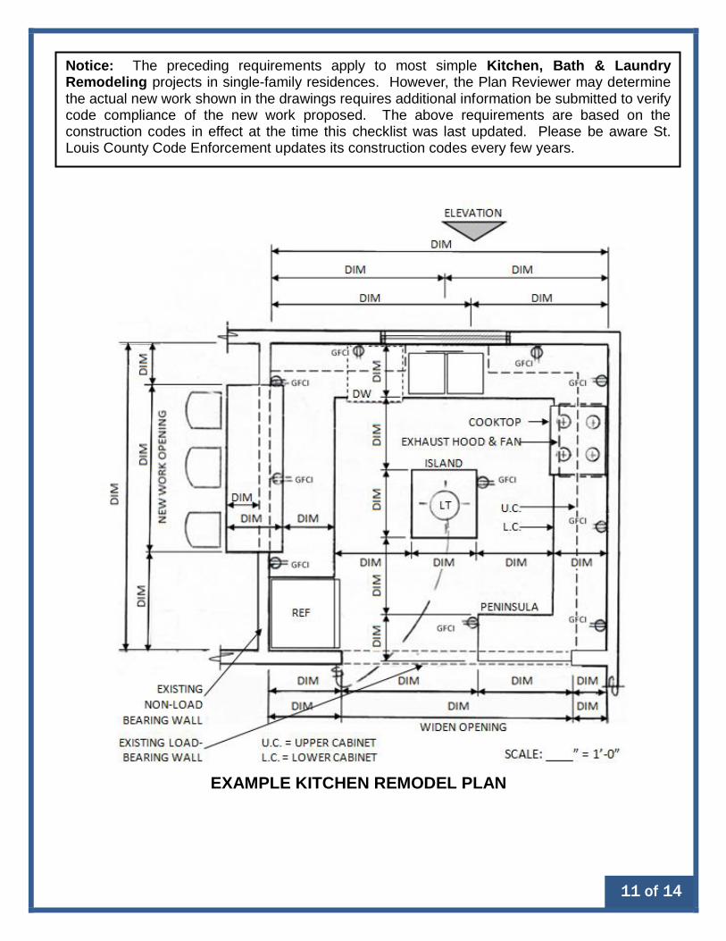
Notice: The preceding requirements apply to most simple Kitchen, Bath & Laundry Remodeling projects in single-family residences. However, the Plan Reviewer may determine the actual new work shown in the drawings requires additional information be submitted to verify code compliance of the new work proposed. The above requirements are based on the construction codes in effect at the time this checklist was last updated. Please be aware St. Louis County Code Enforcement updates its construction codes every few years.
EXAMPLE KITCHEN REMODEL PLAN

12 of 14
EXAMPLE FIREBLOCKING AT SOFFITS
EXAMPLE PLAN OF EXISTING FRAMING & LOADS ABOVE

13 of 14
EXAMPLE MECHANICAL
EXHAUST REQUIREMENTS
EXTERIOR ELEVATION OF ALTERATION

14 of 14
EXAMPLE BATH REMODEL
PLAN