residential wood deck construction guide wood deck construction guide based on the 2009 michigan...
TRANSCRIPT
RESIDENTIAL WOOD DECK
CONSTRUCTION GUIDE
Based on The 2009 Michigan Residential Code
Revised March 19, 2015
The details in this document apply to residential decks only. Construction can not deviate from the details herein unless prior approval is
obtained from the authority having jurisdiction. A copy of this document is required to be on the job site and available for each inspection.
The Following Organizations Support the use of this Guide:
E2.2.9090 Effective 031915

City of Rochester Hills
City of Sterling Heights
City of Auburn Hills
City of Bloomfield Hills
City of Clawson
City of Fenton
City of Ferndale
City of Garden City
City of Grand Haven
City of Inkster
City of Lathrup Village
City of Lincoln Park
City of Livonia
City of Madison Heights
City of Muskegon
City of New Baltimore
City of Northville
City of Norton Shores
City of Novi
City of Oak Park
City of Orchard Lake
City of Plymouth
City of Troy
City of Warren
Charter Township of Shelby
Charter Township of Bloomfield
Charter Township of Canton
Charter Township of Clinton
Charter Township of Grand Haven
Charter Township of Groveland
Charter Township of Macomb
Charter Township of Milford
Charter Township of Oakland
Charter Township of Orion
Charter Township of Port Huron
Charter Township of Royal Oak
City of Wyoming
Village of Holly
Village of Leonard
Village of Webberville
Cities:
Townships: Villages:
Charter Township of White Lake
Autumn Wood Construction
Horizon Builders Inc.
Contractors:
Suppliers:
Dillman & Upton
Wood Deck Construction in accordance with this guide is acceptable
in the following Michigan Communities:
The following Contractors & Suppliers support this Wood Deck Construction Guide:

RESIDENTIAL WOOD DECK CONSTRUCTION GUIDE
CONTENTS
Page General Information.....................................................2 Decking.................................................................................2 Joists........................................................................................3 Beams.....................................................................................5 Joist to Beam Connection.........................................8 Joist Hangers.................................................................8-9 Post Requirements.........................................................9 Post to Beam Connection...................................9-10 Footings.......................................................................11-12 Ledger Board Attachment...............................13-14 Prohibited Ledger Attachments.........................14
Page Ledger Board Fasteners........................................15-16 Deck Stability..............................................................16-20 Guards.....................................................................................21 Guard Post Attachment.........................................21-22 Stair Requirements...................................................23-26 Stair Footing........................................................................26 Stair Lighting......................................................................26 Framing a Chimney/Bay Window.................26-27 Deck Framing Plan.........................................................27 Inspections Required.....................................................28 Community Specific Details..............................29-36
Courtesy of American Wood Council - Leesburg, VA
Page 1

2x4, 2x6, or five
quarter board
(2)8d nails or (2) #8
screws at each joist
1/8” typical gap
after drying
GENERAL INFORMATION
1. This document applies to single level decks only.
2. The overall deck width at the house shall be equal to or greater than the distance the deck extends from the house.
3. All wood in contact with the ground shall be approved pressure treated wood suitable for ground contact.
4. All other wood not in contact with the ground shall be approved pressure treated, or naturally durable wood, such as; Redwood, Cedar, or other approved material.
5. Wood-Plastic Composite shall bear a label indicating the required performance levels and compliance to ASTM-D 7032. Wood-plastic composites shall be installed per the manufacturer’s instructions.
6. All screws, nails, bolts, washers, and nuts used with preservative treated wood shall be hot-dipped zinc-coated galvanized steel, stainless steel, silicon bronze, or copper.
7. Hardware and connectors (joist hangers, or post anchors) shall be protected in accordance with the manufacturer’s recommendations; minimum ASTM-A 653 Type G185 zinc-coated galvanized steel.
8. Information regarding permit, application, plan review, and inspection requirements can be found under “Community Specific Details.”
9. This document is not intended to preclude the use of other construction methods or materials not shown herein.
DECKING
Decking shall be wood 2x4, 2x6, five quarter board, or Wood-Plastic Composite sizes per the manufacturer’s specifications.
Wood decking shall be attached as shown in Figure 1. Decking should also be attached to the rim board with fasteners at 6” O.C.
Each wood decking member must rest on three joists minimum.
Wood-Plastic Composite Decking shall be installed in accordance with the manufacturer’s installation instructions.
Wood-Plastic Composite Decking must be labeled and the manufacturer’s installation instructions shall be onsite for review by the inspector.
A valid ICC Evaluation Report must be provided and approved by the local building official for any other decking products proposed.
Figure 1
Page 2

JOISTS
The joist span L is the distance between the two points supporting the joist and does not include the length of the overhang (See Figures 2A, 2B, and 2C). Use Table 1 to determine allowable joist span LJ. Allowable overhang length is LO as noted in Table 1 or L/4; whichever is less.
Page 3
Courtesy of American Wood Council - Leesburg, VA
Figure 2A. Joist Span – Joist Attached at House and Bearing over Beam
Figure 2B. Joist Span – Joists Attached at House and to Side of Beam
Joist Span (L ≤ LJ): See Table 1
Courtesy of American Wood Council - Leesburg, VA
Joist Span (L ≤ LJ)
See Table 1

Joist Spacing (O.C.)
12" 16" 24" 12" 16" 24"
Species Size Allowable Span² (LJ) Allowable Overhang3 (LO)
Southern Pine
2x66 9'-11" 9'-0" 7'-7" 1'-0" 1'-1" 1'-3"
2x8 13'-1" 11'-10" 9'-8" 1'-10" 2'-0" 2'-4"
2x10 16'-2" 14'-0" 11'-5" 3'-1" 3'-5" 2'-10"
2x12 18'-0"7 16'-6" 13'-6" 4'-6" 4'-2" 3'-4"
Douglas Fir-Larch, Hem-Fir, Spruce-
Pine-fire4
2x66 9'-6" 8'-4" 6'-10" 0'-11" 1'-0" 1'-2"
2x8 12'-6" 11'-1" 9'-1" 1'-8" 1'-10" 2'-2"
2x10 15'-8" 13'-7" 11'-1" 2'-10" 3'-2" 2'-9"
2x12 18'-0"7 15'-9" 12'-10" 4'-4" 3'-11" 3'-3"
Redwood, Western Cedars, Ponderosa
Pine5, Red Pine5
2x66 8'-10" 8'-0" 6'-10" 0'-9" 0'-10" 0'-11"
2x8 11'-8" 10'-7" 8'-8" 1'-5" 1'-7" 1'-9"
2x10 14'-11" 13'-0" 10'-7" 2'-5" 2'-7" 2'-8"
2x12 17'-5" 15'-1" 12'-4" 3'-7" 3'-9" 3'-1"
Courtesy of American Wood Council - Leesburg, VA
Figure 2C. Joist Span – Non-Ledger Deck
1. Assumes 40 psf live load, 10 psf dead load, No. 2 stress grade, and wet service conditions. 2. Assumes L/360 deflection. 3. Maximum allowable overhang cannot exceed L/4 or ¼ of actual main span. Assumes cantilever length/180 deflection with 220 point load
(See Figure 2A and 2C). 4. Incising assumed for Douglas fir-larch, hem-fir, and spruce-pine-fir. 5. Design Values based on northern species with no incising assumed. 6. Ledger shall be a minimum of 2x8 nominal. Where guards are required, outside joists and rim joists shall be a minimum length of 2x8 nominal. 7. Joist length prescriptively limited to 18’-0” for footing design.
Table 1. Maximum Joist Spans and Overhangs1
Page 4 Courtesy of American Wood Council - Leesburg, VA
Joist Span (L ≤ LJ)
See Table 1

BEAMS
Beam span is measured between the supporting posts and does not include the overhang. See Figure 3.
Beam size is determined by using Table 2A for joist framing from one side only. Joists may bear on the beam and extend past the beam centerline up to the lesser of LO or L/4, as shown in Figures 2A and 2C.
Use Table 2B for joist framing from both sides. Beam may overhang past the supporting post up to one-fourth the beam span as indicated in
Figure 3. Beams with multiple members shall be assembled in accordance with Figure 4.
Courtesy of American Wood Council - Leesburg, VA
Figure 3. Beam Span Types
Page 5
Courtesy of American Wood Council - Leesburg, VA
Figure 4. Beam Assembly Details
Beam span (LB): see Table 2A or 2B Beam span (LB): see Table 2A or 2B

Joist Spans (L) Less Than or Equal to:
Species Size4 6' 8' 10' 12' 14' 16' 18'
Southern Pine
2-2x6 6'-8' 5'-8" 5'-1" 4'-7" 4'-3" 4'-0" 3'-9"
2-2x8 8-6" 7'-4" 6'-6" 5'-11" 5'-6" 5'-1" 4'-9"
2-2x10 10'-1" 8'-9" 7'-9" 7'-1" 6'-6" 6'-1" 5'-9"
2-2x12 11'-11" 10'-4" 9'-2" 8'-4" 7'-9" 7'-3" 6'-9"
3-2x6 7'-11" 7'-2" 6'-5" 5'-10" 5'-5" 5'-0" 4'-9"
3-2x8 10'-7" 9'-3" 8'-3" 7'-6" 6'-11" 6'-5' 6'-1"
3-2x10 12'-9" 11'-0" 9'-9" 8'-9" 8'-3" 7'-8" 7'-3"
3-2x12 15'-0" 13'-0" 11'-7" 10'-6" 9'-9" 9'-1" 8'-7"
Douglas Fir-Larch2, Hem-Fir2, Spruce-Pine-Fir2,
Redwood, Western Cedars,
Ponderosa Pine3, Red Pine3
3x6 or 2-2x6 5'-2" 4'-5" 3'-11" 3'-7" 3'-3" 2'-10" 2'-6"
3x8 or 2-2x8 6'-7" 5'-8" 5'-1" 4'-7" 4'-3" 3'-10" 3'-5"
3x10 or 2-2x10 8'-1" 7'-0" 6'-3" 5'-8" 5'-3" 4'-10" 4'-5"
3x12 or 2-2x12 9'-5" 8'-2" 7'-3" 6'-7" 6'-1" 5'-8" 5'-4"
4x6 6'-2" 5'-3" 4'-8" 4'-3" 3'-11" 3'-8" 3'-5"
4x8 8'-2" 7'-0" 6'-3" 5'-8" 5'-3" 4'-11" 4'-7"
4x10 9'-8" 8'-4" 7'-5" 6'-9" 6'-3" 5'-10" 5'-5"
4x12 11'-2" 9'-8" 8'-7" 7'-10" 7'-3" 6'-9" 6'-4"
3-2x6 7'-1" 6'-5" 5'-9" 5'-3" 4'-10" 4'-6" 4'-3"
3-2x8 9'-5" 8'-3" 7'-4" 6'-8" 6'-2" 5'-9" 5'-5"
3-2x10 11'-9" 10'-2" 9'-1" 8'-3" 7'-7" 7'-1" 6'-8"
3-2x12 13'-8" 11'-10" 10'-6" 9'-7" 8'-10" 8'-3" 7'-10"
Table 2A. Deck Beam Spans (LB)1 for Joists Framing from One Side Only
Page 6
1. Assumes 40 psf live load, 10 psf dead load, L/360 simple span beam deflection limit, cantilever length/180 deflection limit, No. 2 stress grade, and wet service conditions.
2. Incising assumed for Douglas fir-larch, hem-fir, and spruce-pine-fir. 3. Design values based on northern species with no incising assumed. 4. Beam depth must be equal to or greater than joist depth if joist hangers are used (see Figure 5, option 3).
Courtesy of American Wood Council - Leesburg, VA
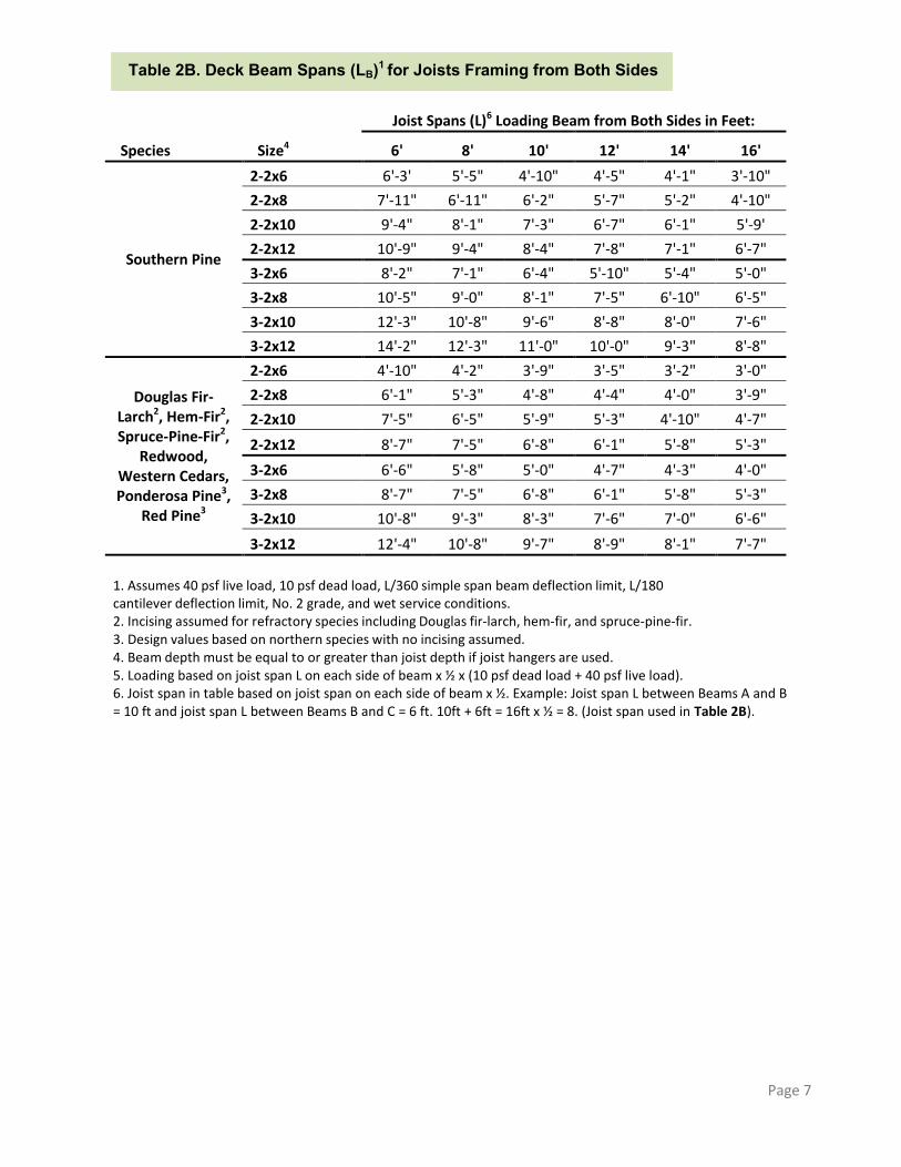
Joist Spans (L)6 Loading Beam from Both Sides in Feet:
Species Size4 6' 8' 10' 12' 14' 16'
Southern Pine
2-2x6 6'-3' 5'-5" 4'-10" 4'-5" 4'-1" 3'-10"
2-2x8 7'-11" 6'-11" 6'-2" 5'-7" 5'-2" 4'-10"
2-2x10 9'-4" 8'-1" 7'-3" 6'-7" 6'-1" 5'-9'
2-2x12 10'-9" 9'-4" 8'-4" 7'-8" 7'-1" 6'-7"
3-2x6 8'-2" 7'-1" 6'-4" 5'-10" 5'-4" 5'-0"
3-2x8 10'-5" 9'-0" 8'-1" 7'-5" 6'-10" 6'-5"
3-2x10 12'-3" 10'-8" 9'-6" 8'-8" 8'-0" 7'-6"
3-2x12 14'-2" 12'-3" 11'-0" 10'-0" 9'-3" 8'-8"
Douglas Fir-Larch2, Hem-Fir2, Spruce-Pine-Fir2,
Redwood, Western Cedars, Ponderosa Pine3,
Red Pine3
2-2x6 4'-10" 4'-2" 3'-9" 3'-5" 3'-2" 3'-0"
2-2x8 6'-1" 5'-3" 4'-8" 4'-4" 4'-0" 3'-9"
2-2x10 7'-5" 6'-5" 5'-9" 5'-3" 4'-10" 4'-7"
2-2x12 8'-7" 7'-5" 6'-8" 6'-1" 5'-8" 5'-3"
3-2x6 6'-6" 5'-8" 5'-0" 4'-7" 4'-3" 4'-0"
3-2x8 8'-7" 7'-5" 6'-8" 6'-1" 5'-8" 5'-3"
3-2x10 10'-8" 9'-3" 8'-3" 7'-6" 7'-0" 6'-6"
3-2x12 12'-4" 10'-8" 9'-7" 8'-9" 8'-1" 7'-7"
Table 2B. Deck Beam Spans (LB)1 for Joists Framing from Both Sides
Page 7
1. Assumes 40 psf live load, 10 psf dead load, L/360 simple span beam deflection limit, L/180 cantilever deflection limit, No. 2 grade, and wet service conditions. 2. Incising assumed for refractory species including Douglas fir-larch, hem-fir, and spruce-pine-fir. 3. Design values based on northern species with no incising assumed. 4. Beam depth must be equal to or greater than joist depth if joist hangers are used. 5. Loading based on joist span L on each side of beam x ½ x (10 psf dead load + 40 psf live load). 6. Joist span in table based on joist span on each side of beam x ½. Example: Joist span L between Beams A and B = 10 ft and joist span L between Beams B and C = 6 ft. 10ft + 6ft = 16ft x ½ = 8. (Joist span used in Table 2B).
JOIST TO BEAM CONNECTION
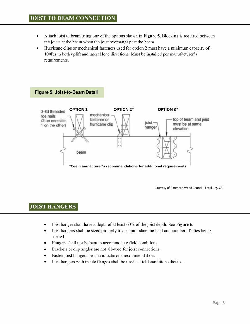
Attach joist to beam using one of the options shown in Figure 5. Blocking is required between
the joists at the beam when the joist overhangs past the beam. Hurricane clips or mechanical fasteners used for option 2 must have a minimum capacity of
100lbs in both uplift and lateral load directions. Must be installed per manufacturer’s requirements.
JOIST HANGERS
Joist hanger shall have a depth of at least 60% of the joist depth. See Figure 6. Joist hangers shall be sized properly to accommodate the load and number of plies being
carried. Hangers shall not be bent to accommodate field conditions. Brackets or clip angles are not allowed for joist connections. Fasten joist hangers per manufacturer’s recommendation. Joist hangers with inside flanges shall be used as field conditions dictate.
Page 8
Courtesy of American Wood Council - Leesburg, VA
Figure 5. Joist-to-Beam Detail
OPTION 1 OPTION 2* OPTION 3*
*See manufacturer’s recommendations for additional requirements

POST REQUIREMENTS
Post size and maximum height shall be in accordance with Table 3. Post height is measured from grade or top of the footing to the underside of the beam. Cut ends of posts shall be field treated with an approved preservative (such as Copper
Naphtenate).
Table 3: Maximum Post Height
Post Size Maximum Height 4x4 4'-0"
4x6 6'-0"
6x6 14'-0"
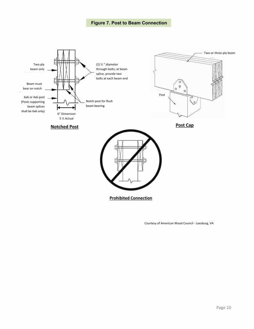
POST TO BEAM CONNECTIONS
Beams shall be attached to the post by one of the acceptable methods shown in Figure 7. 6x6 post minimum required where post supports a beam splice. Attachment of the beam to the side of the post is prohibited.
Page 9
Courtesy of American Wood Council - Leesburg, VA
Figure 6. Typical Joist Hangers
Page 10
Page 9
Courtesy of American Wood Council - Leesburg, VA
Figure 7. Post to Beam Connection
Two-ply
beam only
Beam must
bear on notch
6x6 or 4x6 post
(Posts supporting
beam splices
shall be 6x6 only)
(2) ½ “ diameter
through-bolts; at beam
splice, provide two
bolts at each beam end
Notch post for flush
beam bearing
Post
Two-or three-ply beam
Post Cap
6” Dimension
5 ½ Actual
Prohibited Connection
Notched Post
FOOTINGS
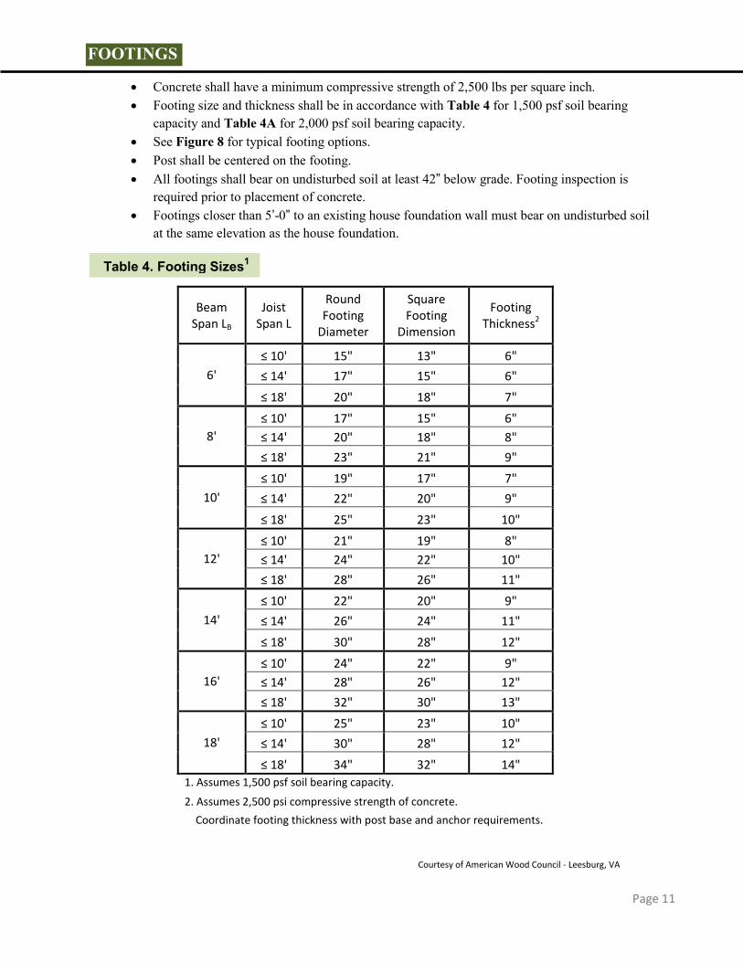
Concrete shall have a minimum compressive strength of 2,500 lbs per square inch. Footing size and thickness shall be in accordance with Table 4 for 1,500 psf soil bearing
capacity and Table 4A for 2,000 psf soil bearing capacity. See Figure 8 for typical footing options. Post shall be centered on the footing. All footings shall bear on undisturbed soil at least 42” below grade. Footing inspection is
required prior to placement of concrete. Footings closer than 5’-0” to an existing house foundation wall must bear on undisturbed soil
at the same elevation as the house foundation.
Beam Span LB
Joist Span L
Round Footing
Diameter
Square Footing
Dimension
Footing Thickness2
6'
≤ 10' 15" 13" 6"
≤ 14' 17" 15" 6"
≤ 18' 20" 18" 7"
8'
≤ 10' 17" 15" 6"
≤ 14' 20" 18" 8"
≤ 18' 23" 21" 9"
10'
≤ 10' 19" 17" 7"
≤ 14' 22" 20" 9"
≤ 18' 25" 23" 10"
12'
≤ 10' 21" 19" 8"
≤ 14' 24" 22" 10"
≤ 18' 28" 26" 11"
14'
≤ 10' 22" 20" 9"
≤ 14' 26" 24" 11"
≤ 18' 30" 28" 12"
16'
≤ 10' 24" 22" 9"
≤ 14' 28" 26" 12"
≤ 18' 32" 30" 13"
18'
≤ 10' 25" 23" 10"
≤ 14' 30" 28" 12"
≤ 18' 34" 32" 14"
1. Assumes 1,500 psf soil bearing capacity.
2. Assumes 2,500 psi compressive strength of concrete.
Coordinate footing thickness with post base and anchor requirements.
Table 4. Footing Sizes1
Page 11
Courtesy of American Wood Council - Leesburg, VA

Beam Span LB,
ft
Joist Span L ft
Round Footing
Diameter
Square Footing
Dimension
Footing Thickness2
6'
≤ 10' 13" 11" 6"
≤ 14' 15" 13" 6"
≤ 18' 17" 15" 7"
8'
≤ 10' 15" 13" 6"
≤ 14' 18" 16" 7"
≤ 18' 20" 18" 8"
10'
≤ 10' 17" 15" 6"
≤ 14' 20" 17" 8"
≤ 18' 22" 20" 9"
12'
≤ 10' 18" 16" 7"
≤ 14' 21" 19" 9"
≤ 18' 24" 22" 10"
14'
≤ 10' 20" 17" 8"
≤ 14' 23" 21" 9"
≤ 18' 26" 23" 11"
16'
≤ 10' 21" 19" 8"
≤ 14' 25" 22" 10"
≤ 18' 28" 25" 12"
18'
≤ 10' 22" 20" 9"
≤ 14' 26" 23" 11"
≤ 18' 30" 26" 13"
1. Assumes 2,000 psf soil bearing capacity.
2. Assumes 2,500 psi compressive strength of concrete.
Page 12
Figure 8. Typical Footing Options
Table 4A. Footing Sizes1 *Note: Table 4A may be used when approved by the local Building Official based on soil conditions.
Footings must bear on solid ground 42” below grade minimum
42” minimum

LEDGER BOARD ATTACHMENT General requirements Ledger board depth shall be greater than or equal to the depth of the deck joists, but not less than a
2x8. The ledger board shall be attached in accordance with one of the conditions shown in
Figures 10 and 11. The existing band board shall be capable of supporting the deck. If this cannot be verified or
existing conditions differ from the details herein, then a free-standing deck or an engineered design is required.
The top of the ledger board and top of the deck joists shall be at the same elevation. Wood I-Joists as shown in Figure 9, located inside the house, must have a 2x band board, or a minimum 1-inch thick engineered wood product (EWP) band board capable of supporting a deck. If a minimum 1-inch EWP or 2x band board is not present, then a free-standing deck is required.
Siding and Flashing The exterior finish, i.e., house siding, must be removed prior to the installation of the ledger board. Continuous flashing with a drip edge, as shown in Figure 10, is required at the ledger board
when attached to wood-framed construction. Flashing shall be copper (attached using copper nails only), stainless steel, UV resistant
plastic or galvanized steel coated with 1.85 ounces of zinc per square foot (G-185 coating). Flashing at a door threshold shall be installed to prevent water intrusion from rain or melting snow.
Figure 9: Wood I-Joists
Courtesy of American Wood Council - Leesburg, VA
Figure 10. General Attachment of Ledger Board to Band Joist or Rim Board
Page 13

PROHIBITED LEDGER ATTACHMENTS The ledger board attachments shown in Figure 12 are prohibited. These conditions require a free-standing deck design.
Courtesy of American Wood Council - Leesburg, VA
Courtesy of American Wood Council - Leesburg, VA
Figure 11. Attachment of Ledger Board to Foundation Wall (Concrete or Solid Masonry)
Figure 12. Prohibited Ledger Attachments
Page 14
LEDGER BOARD FASTENERS
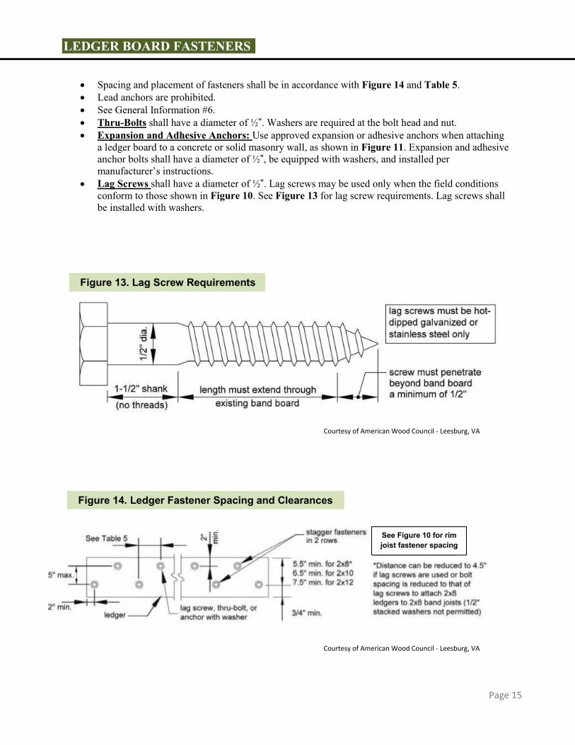
Spacing and placement of fasteners shall be in accordance with Figure 14 and Table 5. Lead anchors are prohibited. See General Information #6. Thru-Bolts shall have a diameter of ½”. Washers are required at the bolt head and nut. Expansion and Adhesive Anchors: Use approved expansion or adhesive anchors when attaching
a ledger board to a concrete or solid masonry wall, as shown in Figure 11. Expansion and adhesive anchor bolts shall have a diameter of ½”, be equipped with washers, and installed per manufacturer’s instructions.
Lag Screws shall have a diameter of ½”. Lag screws may be used only when the field conditions conform to those shown in Figure 10. See Figure 13 for lag screw requirements. Lag screws shall be installed with washers.
Page 15
Courtesy of American Wood Council - Leesburg, VA
Courtesy of American Wood Council - Leesburg, VA
Figure 13. Lag Screw Requirements
Figure 14. Ledger Fastener Spacing and Clearances
See Figure 10 for rim joist fastener spacing

DECK STABILITY
Decks greater than 2 feet above grade shall be provided with diagonal bracing.
Diagonal Bracing Diagonal bracing shall be provided both parallel and perpendicular to the beam at each post as
shown in Figure 15. When parallel to the beam, the bracing shall be bolted to the post at one end and beam at the other. When perpendicular to the beam, the bracing shall be bolted to the post at one end and a joist or
blocking between joists at the other end. Provide blocking between the adjacent joists, when a joist does not align with the bracing location. Decks attached to the house as shown in Figure 17 or 17A do not require diagonal bracing
perpendicular to the house. Diagonal bracing parallel to the house may be omitted at the beam adjacent to the house for a free-
standing deck attached as shown in Figure 16.
Joist Span
Rim Board 6'-0" 6'-1" 8'-1" 10'-1" 12'-1" 14'-1" 16'-1" or and to to to to to to Band Joist less 8'-0" 10'-0" 12'-0" 14'-0" 16'-0" 18'-0"
Connection Details On-Center Spacing of Fasteners
1/2" diameter lag screw1 with 15/32" maximum sheathing
1" EWP 24" 18" 14" 12" 10" 9" 8"
1-1/8" EWP 28" 21" 16" 14" 12" 10" 9"
1-1/2" Lumber 30" 23" 18" 15" 13" 11" 10"
1/2" diameter bolt with 15/32" maximum sheathing
1" EWP 24" 18" 14" 12" 10' 9" 8"
1-1/8" EWP 28" 21" 16" 14" 12" 10" 9"
1-1/2" Lumber 36" 36" 34" 29" 24" 21" 19" 1/2" diameter bolt with
15/32" maximum sheathing and 1-1/2" Lumber 36" 36" 29" 24" 21" 18" 16" 1/2" stacked washers2,7
1. The tip of the lag screw shall fully extend beyond the inside face of the band joist. 2. The maximum gap between the face of the ledger board and face of the wall sheathing shall be ½".
3. Ledgers shall be flashed or caulked to prevent water from contacting the house band joist (see Figures 10, 16, and 17).
4. Lag screws and bolts shall be staggered per Figure 14.
5. Deck ledgers shall be minimum 2x8 pressure-preservative-treated No.2 grade lumber, or other approved materials as established by standard engineering practice. 6. When solid-sawn pressure-preservative-treated deck ledgers are attached to engineered wood products (minimum 1" thick wood structural panel band joist or structural composite lumber including laminated veneer lumber), the ledger attachment shall be designed in accordance with accepted engineering practice. Tabulated values based on 300 lbs and 350 lbs for 1" and 1-1
/8" EWP rim board, respectively. 7. Wood structural panel sheathing, gypsum board sheathing, or foam sheathing not exceeding 1" thickness shall be permitted. The maximum distance between the face of the ledger board and the face of the band joist shall be 1". 8. Fastener spacing also applies to southern pine, Douglas fir-larch, and hem-fir band joists.
Page 16
Table 5. Fastener Spacing for a Southern Pine, Douglas-Fir-Larch, or Hem-Fir Deck Ledger and a 2-inch Nominal Solid-Sawn Spruce-Pine-Fir Band Joist or EWP Rim Board3,4,5,6,8
(Deck Live Load = 40 psf, Deck Dead Load = 10 psf)
Courtesy of American Wood Council - Leesburg, VA

Diagonal Bracing Option
Diagonal bracing as shown in Figures 15A and 15B, is only allowed when the deck is supported by a
ledger attached to the house as indicated in Figures 10 and 11; and lateral load connections as shown in Figure 17 or 17A, are provided near the outside edge of the deck on each side.
Bracing material must be 2x6 preservative treated wood. Bracing must be attached with 3-16D nails at each joist. Nails shall be hot dipped zinc coated galvanized steel or stainless steel.
Courtesy of American Wood Council - Leesburg, VA
Figure 15. Diagonal Bracing Requirements
Page 17

Figure 15A. Diagonal Bracing Attached to Underside of Joist on Single Span Deck
Figure 15B. Diagonal Bracing Attached to Underside of Joists on Double Span Deck
2x6 Lateral V bracing nailed to the underside of
the deck joist with 3-16D nails in each joist.
Lateral load device required as shown in Figure 17 or 17A.
Page 18
2x6 Lateral V
bracing nailed
to the
underside of
the deck joist
with 3-16D
nails in each
joist. Optional layout
for braces
shown dashed
Lateral load device required as shown in Figure 17 or 17A.
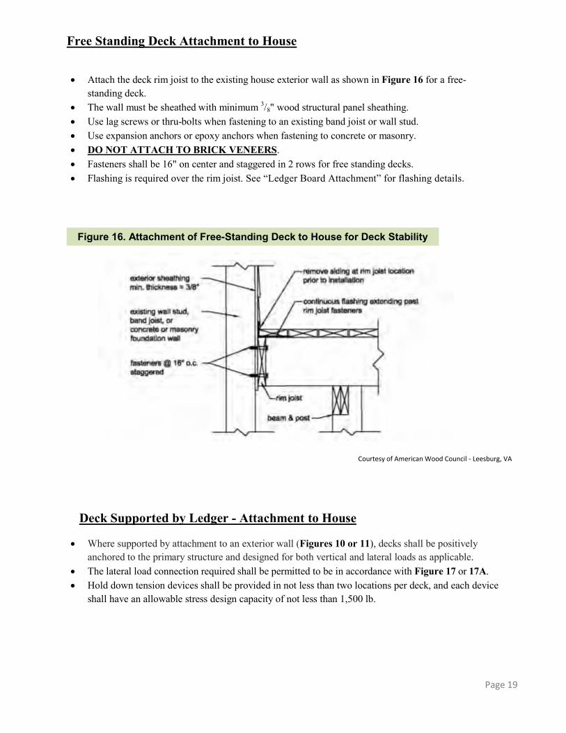
Free Standing Deck Attachment to House
Attach the deck rim joist to the existing house exterior wall as shown in Figure 16 for a free-
standing deck. The wall must be sheathed with minimum 3/8" wood structural panel sheathing. Use lag screws or thru-bolts when fastening to an existing band joist or wall stud. Use expansion anchors or epoxy anchors when fastening to concrete or masonry. DO NOT ATTACH TO BRICK VENEERS. Fasteners shall be 16" on center and staggered in 2 rows for free standing decks. Flashing is required over the rim joist. See “Ledger Board Attachment” for flashing details.
Deck Supported by Ledger - Attachment to House
Where supported by attachment to an exterior wall (Figures 10 or 11), decks shall be positively
anchored to the primary structure and designed for both vertical and lateral loads as applicable. The lateral load connection required shall be permitted to be in accordance with Figure 17 or 17A. Hold down tension devices shall be provided in not less than two locations per deck, and each device
shall have an allowable stress design capacity of not less than 1,500 lb.
Courtesy of American Wood Council - Leesburg, VA
Figure 16. Attachment of Free-Standing Deck to House for Deck Stability
Page 19

Page 20
Courtesy of American Wood Council - Leesburg, VA
Figure 17. Lateral Load Device with Joists Parallel to Deck Joists
Courtesy of American Wood Council - Leesburg, VA
Figure 17A. Lateral Load Device with Joists Perpendicular to Deck Joists
Courtesy of American Wood Council - Leesburg, VA

GUARDS
A guard is required when a deck is greater than 30 inches above grade at any point within 36 inches of the deck edge.
Wood-plastic composites used in guard systems shall be labeled, indicating the performance level and demonstrating compliance with ASTM D 7032. Wood-plastic composites shall be installed in accordance with the manufacturer’s instructions.
Alternative guard systems with a valid ICC Evaluation Service Report must be submitted to the building official for evaluation and approval prior to installation.
Guards shall be no less than 36 inches above the adjacent walking surface or fixed seating. Stair guards shall have a height no less than 34 inches measured vertically from a line connecting the
leading edges of the trends. See Figure 26. Openings in guards shall not allow the passage of a 4-inch diameter sphere through any opening from
the walking surface to the required guard height.
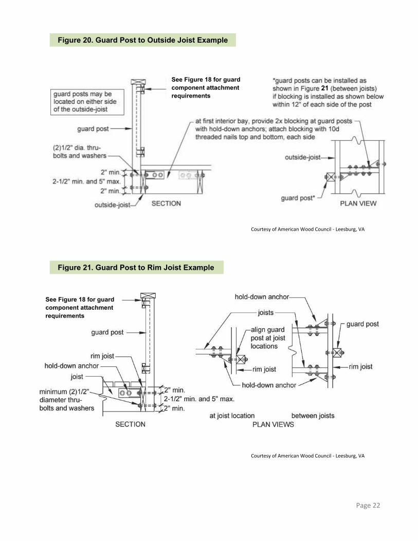
GUARD POST ATTACHMENT
Guard posts shall be 4x4 minimum. Notching of guard posts; as shown in Figure 19,
is prohibited. Guard posts shall be attached as shown in
Figures 20 and 21. Hold down anchors shall have a minimum
capacity of 1,800 lbs and must be installed in accordance with the manufacturer’s instructions.
Page 21
Figure 18. Example Guard Detail
Do not
notch
Figure 19. Post Notches Prohibited
Courtesy of American Wood Council - Leesburg, VA
Page 22
Courtesy of American Wood Council - Leesburg, VA
Courtesy of American Wood Council - Leesburg, VA
Figure 20. Guard Post to Outside Joist Example
Figure 21. Guard Post to Rim Joist Example
See Figure 18 for guard component attachment requirements
See Figure 18 for guard component attachment requirements
21

STAIR REQUIREMENTS
Stair Dimensions
Stairs shall have a minimum clear width of 36 inches.
Stair trends, risers, nosing, and opening limitations shall meet the requirements shown in Figure 22. All tread, riser, and nosing dimensions shall not deviate from one another by more than 3/8” in any flight of stairs.
with a width no less than the stair is required at the top and bottom of each stairway.
Each landing shall be 36” minimum in the direction of travel.
Stairs with a vertical height exceeding 12’0” are required to have an intermediate landing.
A landing, with a width no less than the stair, is required at the top and bottom of each stairway.
Stair Stringers Stair stringers shall be 2x12 minimum. Stair stringers shall not span more than the dimensions shown in Figure 23 for cut and solid stringers. Stair stringers shall be 18” on center maximum.
Page 23
Courtesy of American Wood Council - Leesburg, VA
Figure 23. Stair Stringer Requirements Figure 24. Stair Stringer Attachment Detail
8 ¼”
max.
riser
9” min.
tread
Riser
tread
¾”-1 ¼”
nosing
4” diameter
shall not pass
Figure 22. Treads and Risers
Courtesy of American Wood Council - Leesburg, VA
Max Span = 6’0”
CUT STRINGER
Max Span = 13’3”
SOLID STRINGER
Rim joist or outside joist
Sloped joist hanger, minimum download capacity of 625 lbs; see JOIST HANGERS for more requirements
ATTACHMENT WITH HANGERS
Stair Dimensions

Treads
Tread material shall be equivalent to the decking material specified on page 2. Stairs constructed with solid stringers shall have treads of 2x wood material. See Figure 25.
Treads
Southern Pine 2x6
Doug Fir Larch, Hem Fir, Spruce
2x8
Redwood, Western Cedars, Ponderosa,
Pine, Red Pine 2x10
Page 24
Courtesy of American Wood Council - Leesburg, VA
Courtesy of American Wood Council - Leesburg, VA
Figure 25. Tread Connection Requirements
Figure 26. Stair Guard Requirements
Stair guard is required for stair
with a total rise of 30” or more; see
GUARDS for more information
Stair Handrails Stairs with four or more risers shall have
a handrail on at least one side at a height between 34 and 38 inches.
Handrail height shall be measured vertically from a line connecting the leading edges of the treads. See Figure 26.
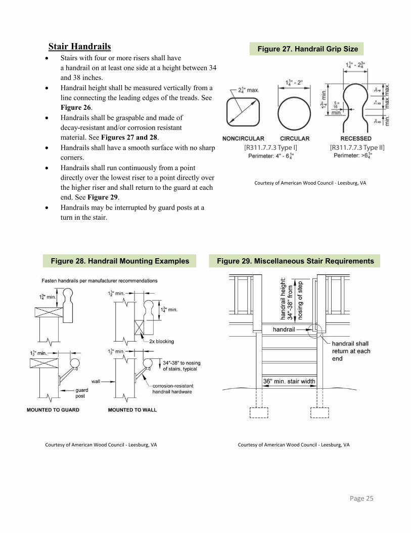
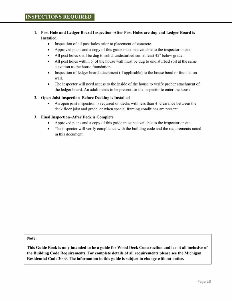
Handrails shall be graspable and made of decay-resistant and/or corrosion resistant material. See Figures 27 and 28.
Handrails shall have a smooth surface with no sharp corners.
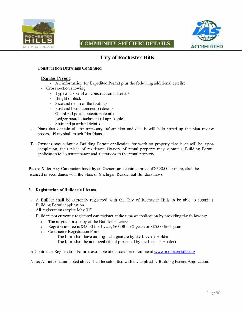
Handrails shall run continuously from a point directly over the lowest riser to a point directly over the higher riser and shall return to the guard at each end. See Figure 29.
Handrails may be interrupted by guard posts at a turn in the stair.
Page 25
Courtesy of American Wood Council - Leesburg, VA
Courtesy of American Wood Council - Leesburg, VA Courtesy of American Wood Council - Leesburg, VA
Figure 27. Handrail Grip Size
Figure 28. Handrail Mounting Examples
Figure 29. Miscellaneous Stair Requirements

STAIR FOOTING
Stair stringers shall be attached to the stair guard posts as shown in Figure 30. Stair guard posts footing shall bear on solid, undisturbed soil 42” below grade minimum. Stringers shall rest on 2x4 bearing block as shown in Figure 30.
STAIR LIGHTING
Stairways shall have a light source at the top landing that provides light to the stairs and landings. The light switch shall be controlled from the inside of the house. Motion detectors or timed
switches are acceptable.
FRAMING AT CHIMNEY OR BAY WINDOW
Framing at chimney or bay window shall be in accordance with Figure 31. Header plies shall be equal to the deck joist size. Header may span 6’0” maximum.
Page 26
Courtesy of American Wood Council - Leesburg, VA
Figure 30. Stair Footing Detail
42” minimum

Courtesy of American Wood Council - Leesburg, VA
Courtesy of American Wood Council - Leesburg, VA
Figure 31: Detail for Framing Around Chimney or Bay Window
Figure 32. Typical Deck Framing Plan
Triple joist hanger, typical
*Trimmer joist may be double if joists are spaced 24” o.c. or if trimmer length is 8’-6” or less
*See Figure 14 for fastener spacing, edge, and end distances
PLAN VIEW SECTION Minimum 1” Clearance required between wood and chimney
DECK FRAMING PLAN
Page 27
INSPECTIONS REQUIRED
1. Post Hole and Ledger Board Inspection–After Post Holes are dug and Ledger Board is
Installed Inspection of all post holes prior to placement of concrete. Approved plans and a copy of this guide must be available to the inspector onsite. All post holes shall be dug to solid, undisturbed soil at least 42” below grade. All post holes within 5’ of the house wall must be dug to undisturbed soil at the same
elevation as the house foundation. Inspection of ledger board attachment (if applicable) to the house bond or foundation
wall. The inspector will need access to the inside of the house to verify proper attachment of
the ledger board. An adult needs to be present for the inspector to enter the house.
2. Open Joist Inspection–Before Decking is Installed An open joist inspection is required on decks with less than 4’ clearance between the
deck floor joist and grade, or when special framing conditions are present.
3. Final Inspection–After Deck is Complete Approved plans and a copy of this guide must be available to the inspector onsite. The inspector will verify compliance with the building code and the requirements noted
in this document.
Page 28
Note:
This Guide Book is only intended to be a guide for Wood Deck Construction and is not all inclusive of the Building Code Requirements. For complete details of all requirements please see the Michigan Residential Code 2009. The information in this guide is subject to change without notice.

Page 29
City of Rochester Hills
1. Types of Building Permit Applications available for Wood Deck construction:
A. Expedited Building Permit Application. A Building Permit can be issued within 48 hours from the
time of application.
B. Regular Building Permit Application. Full Plan Review of construction documents is required. This may occur if the applicant requests a full plan review before starting construction, or if a plan reviewer determines the project needs a full review due to its complexity. The Permit Applicant will be contacted when the Building Permit is ready to be picked up. Plan Review time varies depending on the Building Department’s work load.
2. Information Required For Permit Application A. Building Permit Application (Expedited and Regular Permit Applications) - Forms are available online at www.rochesterhills.org or at the Building Department counter.
Applications shall be filled out completely.
B. Application Fee (Expedited and Regular Permit Applications) - See “Rochester Hills Building Permit Fees” - page 32-33.
C. Plot Plan – Three Copies (Expedited and Regular Permit Applications) - See “Sample Plot Plan” - page 35. - Please show your existing house and location of the proposed deck. - Please indicate the shape and size of the deck, and the distances to all property lines and easements.
D. Construction Drawings – Two Sets (Expedited and Regular Permit Applications) - Construction Drawings shall contain the following:
Expedited Permit:
- Footing, Post, Beam and Joist Layout - See Figure 32 on Page 27
- Footing Size - Post and Beam Span, Size, and Location - Joist Span, Size, and Spacing - Profile of House - Ledger Board (if used) - Include all Dimensions - Drawn to Scale - Exterior of House (Brick or Siding) - Height of Deck - Graph Paper for Drawing provided on page 36
COMMUNITY SPECIFIC DETAILS
Page 30
City of Rochester Hills
Construction Drawings Continued
Regular Permit: - All information for Expedited Permit plus the following additional details:
- Cross section showing: - Type and size of all construction materials - Height of deck - Size and depth of the footings - Post and beam connection details - Guard rail post connection details - Ledger board attachment (if applicable) - Stair and guardrail details
- Plans that contain all the necessary information and details will help speed up the plan review process. Plans shall match Plot Plans.
E. Owners may submit a Building Permit application for work on property that is or will be, upon completion, their place of residence. Owners of rental property may submit a Building Permit application to do maintenance and alterations to the rental property.
Please Note: Any Contractor, hired by an Owner for a contract price of $600.00 or more, shall be licensed in accordance with the State of Michigan Residential Builders Laws.
3. Registration of Builder’s License
- A Builder shall be currently registered with the City of Rochester Hills to be able to submit a
Building Permit application. - All registrations expire May 31st. - Builders not currently registered can register at the time of application by providing the following:
o The original or a copy of the Builder’s license o Registration fee is $45.00 for 1 year, $65.00 for 2 years or $85.00 for 3 years o Contractor Registration Form
- The form shall have an original signature by the License Holder - The form shall be notarized (if not presented by the License Holder)
A Contractor Registration Form is available at our counter or online at www.rochesterhills.org Note: All information noted above shall be submitted with the applicable Building Permit Application.
COMMUNITY SPECIFIC DETAILS

Page 31
City of Rochester Hills
4. Plans Reviewed and Approved
A. Expedited Permits - Complete construction documents are not required, but the Deck shall comply with City Ordinances,
this Wood Deck Construction Guide, and the Michigan Residential Code (MRC). - The Permit Applicant will be notified if the plans do not meet Zoning or Building Code
requirements, or if additional information is required.
B. Regular Permits - Construction drawings and Plot Plans will be reviewed for compliance with City Ordinances, this
Wood Deck Construction Guide, and the Michigan Residential Code (MRC). - Plans are reviewed in the order they are received, based on the application date. Plan review time
varies depending on the Building Department’s work load. - Plans that contain all the necessary information and details will help speed up the Plan Review
process. - The Permit Applicant will be notified if the plans do not meet Zoning Ordinance, or Building Code
requirements, or if any additional information is required.
5. Permit Ready
A. Expedited Permits - The Building Permit can be issued within 48 hours from the date of application as long as the
required information has been provided. The Permit Applicant will be called when the Expedited Permit is ready to be picked up.
B. Regular Permit Applications - The Permit Applicant will be called when the Building Permit is ready to be picked up.
Note: - All Permit fees are due at the time of Permit issuance. - Permit fees may be paid by cash, credit card (excluding VISA), debit card or check. - The Permit shall be issued within 6 months of the application date or the application will be canceled. - Permits that have no activity for more than 6 months may be canceled.
COMMUNITY SPECIFIC DETAILS
City of Rochester Hills
BUILDING PERMIT FEES Wood Decks
1. Application Fee (Expedited and Regular Permits) …………………………………….... . . . .$75.00
- Non-refundable - Due when permit application is submitted
2. Building Permit Fee (Expedited and Regular Permits) - Based on the Construction Valuation of the project excluding site work (refer to fee schedule on
page 33):
Construction Valuation (A) $1,000.00 and under …………………………………………………………………...$75.00
$1,001.00 to $10,000 – $75.00 plus $20.00 for each additional $1,000.00 or part thereof over $1,000.00
(B) $10,000.00 and over –
$255.00 plus $6.00 for each additional $1,000.00 or part thereof over $10,000.00
3. Building Plan Review Fee $1.47 per $1,000.00 of the Construction Valuation, minimum fee …………………… .........$75.00
(Please note: This fee covers two reviews: the initial review and one re-review. A fee of $75.00 per hour will be charged for additional reviews.)
4. Registration Fee for Residential Builder Licenses ……………………………........ One Year $45.00 Two Years $65.00 Three Years $85.00
5. Re-inspection Fee ………………………………………………………………………… ..........$75.00
Page 32
COMMUNITY SPECIFIC DETAILS
Page 33
City of Rochester Hills
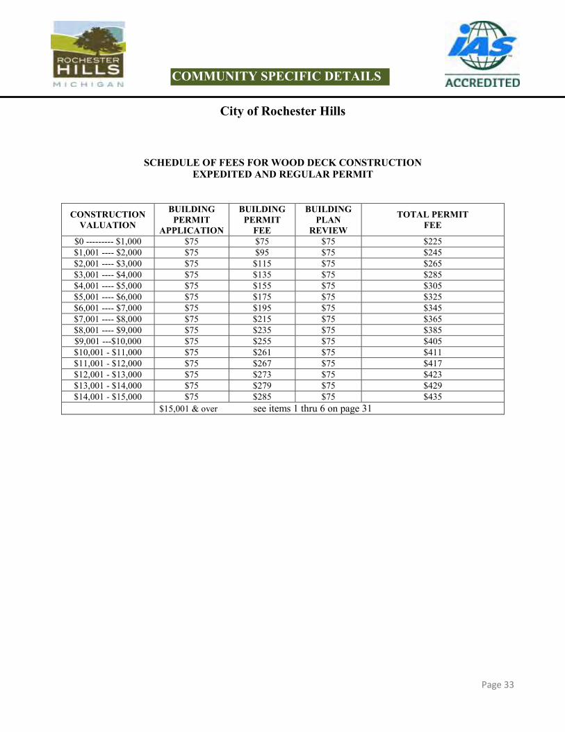
SCHEDULE OF FEES FOR WOOD DECK CONSTRUCTION EXPEDITED AND REGULAR PERMIT
CONSTRUCTION
VALUATION BUILDING
PERMIT APPLICATION
BUILDING PERMIT
FEE
BUILDING PLAN
REVIEW TOTAL PERMIT
FEE $0 --------- $1,000 $75 $75 $75 $225 $1,001 ---- $2,000 $75 $95 $75 $245 $2,001 ---- $3,000 $75 $115 $75 $265 $3,001 ---- $4,000 $75 $135 $75 $285 $4,001 ---- $5,000 $75 $155 $75 $305 $5,001 ---- $6,000 $75 $175 $75 $325 $6,001 ---- $7,000 $75 $195 $75 $345 $7,001 ---- $8,000 $75 $215 $75 $365 $8,001 ---- $9,000 $75 $235 $75 $385 $9,001 ---$10,000 $75 $255 $75 $405 $10,001 - $11,000 $75 $261 $75 $411 $11,001 - $12,000 $75 $267 $75 $417 $12,001 - $13,000 $75 $273 $75 $423 $13,001 - $14,000 $75 $279 $75 $429 $14,001 - $15,000 $75 $285 $75 $435
$15,001 & over see items 1 thru 6 on page 31
COMMUNITY SPECIFIC DETAILS

Page 34
City of Rochester Hills
INSPECTION REQUESTS
The Building Department offers three convenient methods to allow you to request inspections: 1. 24-hour Inspection Request Line – An Inspection may be requested by calling our Inspection Request Line
at (248) 656-4619 and providing the following information: The Street Address of the job site. The Permit Number. The type of Inspection you are requesting. Please Note: This 24-hour Inspection Request Line is for Building Department Inspection Requests only.
2. Online Inspection Requests – Inspections may also be requested by visiting the Building Department’s website at www.rochesterhills.org. By clicking on the City Government tab, highlighting Departments, selecting Building, then Inspection Scheduling and filling in the appropriate information on the Online Inspection Request Form, you can schedule an inspection.
3. QR Code Inspection Scheduling– Scanning the QR Code will gain you direct access to the same Online Inspection Request Form as mentioned above. You will find the QR Code for scheduling inspections on many of our Building Department documents for your convenience.
Inspections scheduled before 6:30 a.m. that have been verified by the Building Department Staff will be scheduled for the same day between 9:00 a.m. and 4:00 p.m. Inspections will be done Monday through Friday. Inspections may be available outside the normal business hours by special arrangement. Additional fees for “After Hours” inspections shall be paid in advance of the inspection. A request to cancel an Inspection needs to be called in to the Building Department at (248) 656-4615 before 9:00 a.m. on the day of the requested Inspection. Please make sure your project is ready for your inspection. If your project is not ready for an inspection, the inspection will not be done and a $75.00 re-inspection fee may be charged. The following items shall be completed or in place at the time of the inspection: - Safe access to the job site and throughout the area to be inspected. - Approved plans on site. - The Street address and lot number posted and visible from the street. - All construction materials and debris contained on the project property. Inspection results will be left on site after each inspection has been completed.
Green Tag Your Inspection has been approved. Inspector’s Report Your Inspection has not been approved. The Inspector’s Report will contain a list of items that need to be addressed before calling for a re-inspection. A $75.00 re-inspection fee will be charged for any items not corrected at the time of the second inspection. Inspections shall be approved before proceeding with the next phase of your construction project. It is your responsibility as the permit holder to check the job site for the inspection results. Please read the information on all Green Tags or Inspector’s Reports. If you have any questions regarding this information, please call (248) 656-4615 between 8:00 a.m. and 9:00 a.m. to speak with the Inspector that wrote the Inspector’s Report.
COMMUNITY SPECIFIC DETAILS

Page 33
Page 35
City of Rochester Hills
Please make sure the location of your deck meets the following requirements:
Decks cannot be built within any easement or right-of-way Uncovered decks may not be built more than 10 feet into the required front yard All decks shall be 5 feet or more from the side property line Decks cannot be located within a steep slope setback. Please contact the Building Department at
(248) 656-4615 regarding restrictions for building on properties with steep slopes.
COMMUNITY SPECIFIC DETAILS

Page 36
City of Rochester Hills
Project Address: _________________________________________________________
COMMUNITY SPECIFIC DETAILS