resilient housing design for tsunami prone andaman and
TRANSCRIPT

Rochester Institute of Technology Rochester Institute of Technology
RIT Scholar Works RIT Scholar Works
Theses
12-2017
Resilient Housing Design for Tsunami Prone Andaman and Resilient Housing Design for Tsunami Prone Andaman and
Nicobar Islands in India Nicobar Islands in India
Sabyasachi Das [email protected]
Follow this and additional works at: https://scholarworks.rit.edu/theses
Recommended Citation Recommended Citation Das, Sabyasachi, "Resilient Housing Design for Tsunami Prone Andaman and Nicobar Islands in India" (2017). Thesis. Rochester Institute of Technology. Accessed from
This Thesis is brought to you for free and open access by RIT Scholar Works. It has been accepted for inclusion in Theses by an authorized administrator of RIT Scholar Works. For more information, please contact [email protected].

i
RESILIENT HOUSING DESIGN FOR TSUNAMI PRONE ANDAMAN AND NICOBAR
ISLANDS IN INDIA
SABYASACHI DAS
A thesis submitted in partial fulfillment of the requirements for the
Degree of Master of Architecture
Department of Architecture
Golisano Institute for Sustainability
Rochester Institute of Technology
Rochester, New York
December 2017

ii
Sabyasachi Das, 2017
All Rights Reserved

iii
COMMITTEE APPROVAL:
___________________________________________________________
Nana-Yaw Andoh,
Assistant Professor, Department of Architecture
Rochester Institute of Technology
___________________________________________________________
Dr. Gabrielle Gaustad
Associate Professor, Golisano Institute of Sustainability
Rochester Institute of Technology
____________________________________________________________
James Yarrington
Adjunct Professor of Architecture and Director of Planning & Design
Rochester Institute of Technology

iv
ACKNOWLEDGMENTS
First, I would like to thank my thesis committee members, Mr. Nana-Yaw Andoh, Dr. Gabrielle
Gaustad and James Yarrington for their guidance and review of this document, and for devoting
their time and attention during their busy schedule. I would also like to thank the Head of
Department of Architecture Mr. Dennis Andrejko for his support through this process. Sir, I am
deeply grateful for your feedback. I would also like to express my gratitude to the other
architecture and sustainability faculty for their assistance and support, and for being a constant
source of motivation. Thank you for sharing your experiences, visions and analysis, which have
contributed to my growth as an architecture student.
I would also like to thank my parents for their endless support and encouragement. Last but not
the least, I would like to thank Rochester Institute of Technology (RIT) for providing me with
the facilities and giving me a platform to purse my dream to become an Architect.

v
PREFACE
Over the first twenty years of my life I visited Andaman and Nicobar islands numerous
times. When the 2004 Tsunami struck and caused major destruction to life and property on these
islands, I developed a vision to provide a resilience solution which could sustain such natural
disasters in the future. As a student of Masters of Architecture with a Bachelor’s degree in
Mechanical Engineering, I found the opportunity to draw light to my vision and was drawn to
designing resilient buildings.
With increased changes in the physical world around us owing to development,
globalization and other factors, there has been an increase in the number of natural and man-
made disasters. This understanding has motivated me to contribute to the society through my
knowledge of engineering and architecture.
The goal of this thesis is to act as a guide for architects, planners and builders to develop resilient
designs for houses in coastal areas prone to Tsunami, hurricanes and flash floods. The motive is
to develop a house which is habitable by regional population with better comfort levels and has
the ability to survive a natural disaster. This thesis will discuss strategies to influence and inform
the field of resilient model housing to keep the populations living in the disaster prone areas safe.
This thesis is based on logical decision making to inform the development of houses, which are
resilient to natural disasters described above. The aim of this thesis is to provide solutions to
develop resilient houses with better comfort levels in Andaman and Nicobar Islands, India as an
adaptation measure for people inhabiting this area.

vi
ABSTRACT
Human settlement along coastal areas has grown dramatically over the last two decades.
Unfortunately, coastal areas are prone to natural disasters caused by climate change and tectonic
shifts underwater in the adjacent water bodies, resulting in loss of life and property. Tsunami is a
form of natural disaster which occurs because of earthquakes under oceans and seas creating
large waves which flood or wash out any coastal cities or islands located in the area impacted.
In 2004 the Indian Ocean Tsunami had an enormous impact on the coastal cities in Southeast
Asia causing loss of thousands of lives and making millions homeless. One region that bore the
worst impacts of this tsunami was the Andaman and Nicobar Islands in India, located in the Bay
of Bengal. Rehousing for those who lost their houses was the biggest post disaster issue as these
islands were completely washed out. People built temporary housing until they moved to
permanent houses, which took about two years to develop. The temporary houses built by the
disaster stuck population were unsustainable. Being an island town, natural disasters such as
tsunami due to tectonic shifts or rising water levels globally could reoccur bringing even more
damage.
This thesis addresses the development of a resilient house as a solution for preventing
homelessness caused by coastal natural disasters and act as an informative guide for houses that
are to be built to make them resilient to similar natural disasters. Resilient housing is a viable
solution to reduce the loss of housing post a disaster and to protect human lives through the
disaster. This proposed prototype design of the core and shell of the house which is resilient and
based on the characteristics of the region is based on studying and analyzing existing research in
the field of tsunami's and their impact. This thesis takes into account the climate of the region
and has features that ensure better comfort levels. The development of this thesis involved a
study of Tsunami and its impacts, social aspects of the study area, relationship between
structures and their resilience to Tsunami, the regulatory requirements of the government
regarding incorporation of resilience in building design, a climate characterization of the region.
This was followed by an analysis of the information gathered, based on which a prototype design
of a house resilient to impacts of Tsunami has been proposed.

vii
LIST OF FIGURES
Figure No. Figure Content
1.1 Generation of a Tsunami
1.2 Location of Andaman & Nicobar Islands in Subcontinent of India
2.1 Tsunami Wave Amplitude
2.2 Generation of a Tsunami (1)
2.3 Generation of a Tsunami (2), (3)
2.4 Generation of a Tsunami (4), (5)
2.5 Generation of a Tsunami (6), (7), (8), (9)
2.6 Generation of a Tsunami (10)
2.7 Seismic Zones in India
2.8 Impacts of Tsunami
2.9 Satellite image of a zone inundated by tsunami water
2.10 Images of Impact of Indian Ocean Tsunami 2004, Andaman and Nicobar
Islands
2.11 Square model details (side view)
2.12. (a) Case 1
2.12. (b) Case 2
2.13. Comparison of Tsunami Load on Case 1 vs. Case 2
2.14 Location of Andaman and Nicobar Islands in South East Asia
2.15 Map of Andaman & Nicobar Islands
2.16 Monthly Diurnal Averages.
2.17 Wind wheel.
2.18 Psychometric Chart
2.19 Sun Shading Chart
3.1 Process Study sketches
3.2 (a) Building Mass & Form in a rectangular house
3.2 (b) Building Mass & Form in proposed design
3.3.
3.4. (a) Building Core layout
3.4. (b) Floor Plan of Proposed Design with drainage plan
3.5 Building Section
3.6 (a) Airflow
3.6 (b) Airflow
3.6 (c) Application of Bernoulli effect via narrow core layouts
3.6 (d) Ventilation Cooling
3.7 Roof Plan
3.8 (a) Sea Facing Elevation
3.8 (b) Side Elevation

viii
3.8 (c) Land-end Elevation
3.9 3D Perspective view of proposed design
3.10 Psychrometric Chart
A.A. 1 Square model details (side view)
A.A.2 Testing instrumentation details
A.A.3. Flow diagram of the experiment test lab setup of the simulated tsunami
experiment
A.A.4. Bore front velocity data: experimental VS existing formula
A.B.1. Plane and elevation layout of the structure (in mm)
A.B.2. Model Boundary conditions and geometric dimension
A.B.3. (a) Case 1
A.B.3. (b) Case 2
A.B.4. Comparison of Tsunami Load on Case 1 vs. Case 2

ix
LIST OF TABLES
Table
No. Table Content
A.C.1.
General Design factors to construct buildings in coastal areas as proposed by
National Disaster Management Authority
A.C.2. Specific design values/factors for Andaman & Nicobar Islands
x
LIST OF ABBREVIATIONS
NOAA National Oceanic and Atmospheric Administration
Mt Metric Tonne
Mph Miles per hour
FEMA Federal Emergency Management Agency
IPCC Intergovernmental Panel on Climate Change
NIDM National Institute of Disaster Management
RC Reinforced Concrete
CGI Corrugated Galvanized Iron sheets

xi
Content Page No.
Committee Approval iii
Acknowledgements iv
Preface v
Abstract vi
List of Figures vii
List of Tables ix
List of Abbreviations x
Part 1: OVERVIEW 1
1.1 Introduction 2
1.2 Problem Statement 6
1.3. Aim & Objectives 8
1.4 Literature Review 9
PART 2: THE METHOD 19
2 Methodology 20
2.1 Tsunami 21
2.1.1 Generation of a Tsunami 22
2.1.2. Characteristics of Tsunamis 26
2.1.3. Impacts of Tsunami 27
2.2. Relationship between Structure Design and its resilience to Tsunami 30
2.2.1. Hydrodynamic Forces 32
2.2.2. Experiment-1 32
2.2.3. Experiment-2 35
2.3 Social Study of Andaman And Nicobar Islands 38
2.4. Regulatory Requirements of Government of India to inculcate Tsunami
Resilience in Structures
42
2.4.1. Design Criteria 42
2.4.2. Specific Recommendations For Andaman & Nicobar Islands 43
2.4.2.1. Structural Measures: 43
2.5. Climate Characterization 45
2.6 Analysis and Strategies 48
PART 3: APPLICATION OF STRATEGIES 51
3.0. Application Of Strategies - Concept Design 52
3.1 Building Mass & Form 52
3.2. Columns 55
3.3. Building Core 56
3.4. Lateral Support 57
3.5. Cooling and Ventilation 58
3.6. Roofing and Shading 60
3.7. Suggested materials for Proposed Design 62
3.8 Cost of Construction of Proposed Design 66
TABLE OF CONTENTS

xii
3.9 Psychrometric Results on application of Passive techniques 67
3.1 Thesis Way Forward 68
PART 4: CONCLUSION 69
4 Conclusion 70
BIBLIOGRAPHY 71
APPENDIX - PART A: Experiment 1 79
APPENDIX - PART B: Experiment-2 84
APPENDIX – PART: C 90

1
PART 1: OVERVIEW

2
1.1 INTRODUCTION
Water is a key element for human survival and its presence along land has fostered the
growth of some of the largest civilizations. Water covers 71% of the earth’s surface and 96.5%
of this water is in saline form found in oceans and seas; and only the remaining 3.5% is fresh
water [47]. Ironically water which is essential for the wellbeing of humans also takes human
lives through natural disasters. Tsunamis are comprised of series of large waves of ocean or
seawater, which flood into adjoining coastal areas causing flash floods and destruction of
properties with their smashing thrust [48]. They are a result of geological changes namely
tectonic shifts, underwater volcanic eruptions or combination of both. These large tidal waves
are generated by vertical motion among tectonic faults. As illustrated in Figure 1.1 below, an
earthquake displaces volumes of water pushing them up and thereby triggering the oscillation of
water at great speed. The water is pulled back from the nearest shore which is observed as
receding tides, and then as the water returns to the surface it creates a series of strong high speed
waves which increases in height as the water becomes shallower near the shore and its speed
reduces from 450-500 mph to 18mph near the coastal line [49].
Fig. 1.1 Generation of a Tsunami
Source: Taranaki Emergency Management, Government of New Zealand [63]

3
These waves can destruct the shore even in when they have heights like 5 meters. According to
the National Oceanic and Atmospheric Administration (NOAA), the occurrence of tsunamis
around the world has been accountable for over 420,000 lives lost and billions of dollars in
economic damage in the form of destruction of coastal structures and habitat since 1850 [1].
These casualties were mostly caused by local tsunamis that occur occasionally once a year
somewhere around the world.
One of the largest Tsunami disasters in recent times was the Indian Ocean Tsunami that
struck on December 26, 2004. This tsunami originated under the Indian Ocean near Banda Aceh,
Indonesia, caused by an earthquake of 9.1-9.4 on Richter scale [2]. The tsunami waves from this
earthquake, also called Sumatra-Andaman earthquake travelled long distances in different
directions. Eleven countries were affected by this natural disaster. A total of 280,000 people lost
their lives and more than 1.5 million people were left homeless. According to the Asia Disaster
Preparedness Center, the damages were close to 6 billion US dollars [3].
Andaman and Nicobar Islands is an archipelago, which are Indian Union Territories in
the Bay of Bengal near the eastern coast of the country (See Figure 1.2 below). These islands
were closest to the epicenter of the Indian Ocean 2004 Tsunami and were among the most
affected zones in the disaster stuck area. These islands that had a small population of 350,000
people bore highly intense damage [34]. The death toll of the island exceeded 12,800 and 50,000
people were affected in the 38 islands hit by the tsunami. 14,000 dwelling units were damaged
by it, as waves up to 9 meters high reached the shores and flash floods were traced to at least one
mile inland [4]. According to the local government reports, a total of 9,565 intermediate shelters
were made for the survivors and an estimated 15,000 Metric Tons (MT) of construction material
was transported to the islands [42]. Housing became a major issue after the disaster as most
people had lost their houses. It took long periods of time to create shelter for the people as these
were island towns where shipping ports and airstrips had got damaged due to Tsunami. It had
become immensely difficult to make relief reach the affected areas from the mainland country, as
the island generally relies on mainland imports. The damage caused prolonged economic damage
on the islands as the fishing and the agriculture industries which are the predominant industries
in the islands were greatly affected. The Andaman and Nicobar Islands houses a strategically
important defense port for India in the Bay of Bengal, which also got disrupted [70]. Agricultural

4
fields were either washed out or salinized due to temporary inundation of seawater as some
saline water remained in the island in natural depressions and man- made topographic changes.
As these islands are very close to the tectonic plate faults of the Indian, Australian and
the Eurasian plate [50], and a similar even in this region is highly possible in the future, that may
cause recurring damasge. As per the Intergovernmental Panel on Climate Change (IPCC 2001),
global sea water level will rise between 110 and 880 mm by the year 2100 [71]. The rise in sea
water level can lead to saline water inundating inland surface causing flooding [46]. Considering
that these islands are prone to a tsunami in the future and globally rising seawaters, it is very
important to make buildings in these islands that are resilient to these foreseen disasters.
Fig. 1.2. Location of Andaman & Nicobar Islands in
Subcontinent of India Source: Maps Open Source Website [64]

5
The damage to residential buildings on the islands was large. Numerous buildings with
reinforced concrete construction did not survive the impacts of the Tsunami as they didn’t have
any seismic code incorporated in their design [4]. The buildings which had seismic detailing in
their column structures survived better. During the Tsunami some ground shaking occurred in
particular areas of the islands that lead to liquefaction and cracking of floors in houses. The
houses which were made with lighter construction materials such as wood and tin sheet metal
roofs, or a combination of wood and masonry survived the impacts of the shock better. Even the
old masonry structures on the islands survived better in response to the ground shaking of the
impact. In Port Blair, the main town of the islands, owing to a lack of open space around
buildings that aids in lateral deformation during the Tsunami, the buildings suffered cracks in
their building shell.
The houses constructed post the 2004 tsunami are mostly built on higher plinths, with
masonry walls, RC isolated footings, steel structures. Bamboo boards are also used as a building
material [86]. Sloping roofs are made of tin sheet metal or Corrugated Galvanized Iron sheets
(C.G.I.) [86]. These houses have more open spaces around them that would support lateral
deformations during a Tsunami.
As per Resilient Design Institute’s definition, “resilient design is the intentional design of
buildings, landscapes, communities, and regions in order to respond to natural and manmade
disasters and disturbances” [51]. The development of resilient houses that can withstand
disasters is a viable solution to areas prone to natural disasters. The purpose of this thesis is to
propose a housing prototype along coastal areas that is resilient against future natural disasters
and can be used by the users for a prolonged time with enhanced comfort levels in context to
climate of the region. This thesis involved a literature review to understand the science behind
the causes of Tsunami, social norms of infrastructure on the islands. The literature review was
followed by an analysis and a proposal of a resilient house design. The aim of this thesis is to
develop a resilient housing design, which can be used by people as a guideline in the area to help
them adapt to the impacts of future Tsunamis and create a design which could be accepted
socially for regular habitation.
6
1.2 PROBLEM STATEMENT
Tsunamis are a series of tall waves with large amount of energy and water contained in
them [48]. These waves cause mass destruction by their smashing force due to their high-speed
and large voluminous wall of water travelling towards the shore and washing it away. Tsunamis
occur, at very little warning, by the movement of the tectonic plates which is felt as an
earthquake. It is difficult to predict tsunamis well in time to provide time for evacuation as
according to the NOAA, “neither seismometers nor coastal tide gauges provide data that allow
accurate prediction of the impact of a tsunami at a particular coastal location” [5]. Tsunamis
have led to the loss of more than 420,000 lives across the world since 1850 [1]. The Indian
Ocean 2004 tsunami has been cited to be the most damaging with 280,000 deaths in the 11
affected countries and 1.5 million people left homeless. The area of this study, the Andaman and
Nicobar Islands, which were closest to the epicenter of the earthquake that caused the Tsunami,
suffered a death toll of 12,800 and 50,000 people getting affected. The waves moved at high
speeds of 500mph across the Indian Ocean and took the form of destructive high waves of 10m
height travelling at a speed of 20mph along shallow coastal waters. 14,000 dwelling units in the
islands were damaged by the waves that reached shores and caused flash floods up to one mile
inland [4]. There was damage to the jetties, trade and transport links, power infrastructure and
water supply systems. This left the people living in the islands homeless and making them live in
makeshift tents for months before they could move into semi-permanent shelter. Being island
towns which are dependent on the mainland for regular import supplies, even reach of relief
supplies and new construction materials got delayed due to logistic delays and damages to its
jetties. The tsunami led to the caused severe damage to the local economy especially the islands
fishing and agriculture industries as lands were salinized or submerged. Considering that the
islands are close to the Indian, Australian and the Eurasian fault plates, there are chances that an
earthquake underwater triggering Tsunami could reoccur. The population of the islands is
380,000 observed in 2012, an increase of 8% from the 350,000 population of the island in 2004
[34]. Considering the fact that a tsunami may reoccur, the risk of number of people losing life
and property is higher. In precedence to the delay caused in the reach of relief supplies to these
islands after the disaster from the mainland due to possible logistic delays, a possible disaster
situation would affect them similarly even today.

7
In order to address this problem, it is important to develop housing for the people who
inhabit such tsunami prone regions that is resilient to the impacts of a Tsunami as an adaptation
method to protect human lives and their property in case of a disaster. This thesis is based on the
study of literature and Design guidelines of building infrastructure in Tsunami affected areas of
Andaman and Nicobar Islands by Government of India and proposes a concept resilient design
prototype of houses. The purpose of this research is to inform architects, planners and builders
through the development of a tsunami resilient design of a house as a guide for building new
houses or retrofitting houses in areas prone to Tsunami, hurricanes and flash flooding.

8
1.3. AIM & OBJECTIVES
In view of the background and problem statement mentioned in the sections above, this
research had the following aim:
To propose the design of a house that is resilient to impacts of a Tsunami as an adaptation
measure in Tsunami prone areas of Andaman & Nicobar Islands, India while accounting for the
climate of the region to provide better comfort levels.
To achieve the above state aim, following objectives were developed:
1. To conduct a study of Tsunami and its impacts.
2. To study the relationship between buildings structure and its resilience to Tsunami.
3. To conduct a background study of Andaman and Nicobar Islands.
4. To review the regulations and guidelines for design criteria for Tsunami resilience in buildings
in India.
5. To do a Climate Characterization of the region.
6. To create the house design based on analysis of information gained in Objective No. 1. to 5
using Revit 17 as a design tool.

9
1.4. LITERATURE REVIEW
Natural disasters have become recurrent in coastal areas across the world in the last two
decades. Along with storms and floods, tsunamis have caused enormous damage in the regions
of occurrence over the years. The 2004 Indian Ocean tsunami caused damage to 11 countries,
with Banda Aceh, Indonesia and Andaman & Nicobar Islands, India suffering the most damage.
Hock Lye Koh in his paper “Earthquake and Tsunami Research in Universiti Sains Malaysia
(USM): The Role of Disaster Research Nexus” [6] talks about the impact of tsunami and
methods to reduce its impact in the different studied simulated Tsunami conditions. The paper
also discusses methods that can be implemented to cope with soil salinity changes due to water
inundation and assisting vegetative rehabilitation, and a model for estimation of tsunami forces
on coastal structures. The paper analyses all of these with an objective to encourage researchers
to collaborate further in the development of resiliency to face future earthquakes and tsunamis
better.
Thorne Lay’s paper on the 2004 Indian Ocean Tsunami titled “The Great Sumatra-
Andaman Earthquake of 26 December 2004” [2] discusses the earthquake that caused the
tsunami in the region. In this paper, Lay has talked about the two most powerful earthquakes in
the past 40 years that ruptured a 1600 km stretch of the boundary between Indo- Australian and
South-Eastern Eurasian plates and also a slip occurred north of the Andaman and Nicobar Islands
over a period of fifty minutes. He has further discussed the impact of this on the neighboring
countries and Andaman and Nicobar Islands. This paper supported this thesis by building an
understanding of qualitative and quantitative impacts of a tsunami.
In “Natural Disaster, Mitigation and Sustainability: The Case of Developing Countries”
[7] the authors Souheil El-Masri & Graham Tipple have discussed the method of applying
sustainable development principles to natural disaster mitigation in developing countries. Land-
use planning and policies; building materials, shelter design and methods of construction; and
institutional organization at local, provincial, national and international levels have been
considered. These aspects have been described based on the knowledge of settlement of humans
in reference to particular disaster situations and housing for the underprivileged in developing
nations. The paper discusses a spectrum of conditions and the problems associated with them
along with the respective solutions. It further says that transforming ideas into implementable

10
strategies requires creative combinations of solutions with customization to a particular disaster
situation. A detailed study of the circumstances and the disaster type is essential for the proposed
adjustments and changes to accommodate human user better.
“Understanding and Applying the Concept of Community Disaster Resilience: A capital-
based approach” by Joseph S. Mayunga [8] speaks about the limitation of understanding of the
concept of Resiliency. The paper discusses the limitation of operation and understanding of the
concept of resilience. In this study, Mayunga has developed a conceptual and methodological
framework for the analysis, measurement, and mapping of community disaster resilience. His
method involved first an examination of the definition of the concept followed by a review of the
currently used framework to measure resilience of the community. He has further proposed a
method for community disaster resilience.
In the paper “Simulated Tsunami bore impact on an onshore structure” by Al-Faesly, et al
[9] motivated by the recent disasters investigate the effects of Tsunami waves in order to propose
an appropriate formulation to analyze tsunami loads better. The paper involves a great deal of
practical experimentation through a fabricated model structure that was subjected to hydraulic
bores in a simulation of rapidly advancing broken tsunami waves. The experiments generate
evident data which could be used to aid further understanding and development of resilient
structural systems.
Folke et al. in their paper “Resilience and Sustainable Development: Building Adaptive
Capacity in a World of Transformations” [10] have emphasized that natural resource governance
policies have been built on two major errors and that the world needs to recognize these errors
and work to correct them. The first error is the assumption that human use causes ecosystem
responses that are linear, controllable and predictable. The other is that humans and nature and
its systems are independent, which is not the case. The authors have proposed resilience as a
method to understand how to build and develop adaptive capacity in this world constantly
marked by transformations. They have further discussed two tools that can be used for building
resilience in socio-ecological systems. These include active adaptive management and structured
seniors. The aim of the tools according to the authors is to facilitate a social context among

11
system structures to allow learning of adaptive methods without affecting development in the
future.
Adger et al in their article “Social-Ecological Resilience to Coastal Disasters” [11] speak
about the necessity to build socio-ecological resilience into social systems to limit the
vulnerability of coastal economies/regions. The authors state that large scale processes like
economic activities affect resilience capacity and anthropogenic activities only worsen the risk
that disasters pose. Building this resilience would require both people and the governance system
to contribute. According to the authors, efforts need to be made at multiple social networks with
inter-level cooperation and interaction to aid in building resilience.
Terry Canon in chapter titled “Vulnerability Analysis and the explanation of ‘Natural’
Disasters’ of his book “Disasters Development and Environment” [12] has argued that
vulnerability of people to impacts of a natural hazard is affected by social and economic factors.
If a group of people have the economic means to prepare for a disaster, they can become resilient
to the effects of that hazard. He added how social systems like social institutions such as unions,
NGOs and cooperatives allocate resources to reduce impacts of a disaster are important. He
further states that the aim of preparedness for a disaster should be to reduce impact of the hazard
by reducing vulnerability of the people that may be carried out by constructing buildings that are
disaster resilient.
Theo Schilderman in his study “Building Research and Information” [13] speaks about
the adaptation of traditional shelters for disaster mitigation and reconstruction. He states that
development affects vulnerability of people to a disaster and occurrence and scale of disasters. If
development goes wrong, vulnerability of poor people increases. In addition, if a disaster strikes
it sets back development. The author has emphasized the importance of community based
disaster mitigation stating that it can help reduce vulnerability by involving local knowledge,
popular approaches, and social capital while addressing their weaknesses. Some community
based mitigation examples mentioned by the author include encouraging participation, learning
from past, building local capacity, influencing formal education, associating with communities,
working with local artisans and builders, and documenting and sharing lessons.

12
The Hyogo Framework for Action 2005-2015 adopted at the World Conference on
Disaster Reduction in Hyogo Japan 2005 [14], urged governments to integrate assessment of
disaster risk into urban planning activities and management of human settlements that are
disaster prone. In addition, it asks governments to incorporate considerations for disaster risk in
planning activities for key infrastructure projects, including but not limited to “criteria for
design, approval and implementation of such projects and considerations based on social,
economic and environmental impact assessments.” The Framework further calls out
governments to include disaster risk concerns in planning and management for rural
development, especially in coastal flood plain areas, by efforts such as identifying land zones,
revising existing building standards, codes, rehabilitation and reconstruction practices, with the
overarching objective of making them more suitable to local requirements.
The role of construction professionals in contributing to disaster resilience has been
emphasized by Bosher et al., 2007 [15] where they have stated that construction professionals
who have the experience and knowledge to design, build, retrofit and operate buildings that
essentially bespoke assets into the Disaster risk management framework should be included in
the design process. The paper further discusses taking an integrated approach in completion of a
building project.
In his book “The Environment as Hazard” Burton [16] has categorized human responses
to natural hazards into short-run and long actions. They discuss that short run actions focus on
adjustment and long-run actions involve adaptation. They categorize the method of designing a
disaster resilient house as an adjustment. An example of adaptation would be locating a
community in a way that the houses are in an area that is away from most impact of disaster.
The paper "Geotechnical and structural damage in Tamil Nadu, India, from the December
2004 Indian Ocean tsunami” by Maheshwari et al. [4] talks about the inspection of the scenario
after the 2004 Indian Ocean Tsunami. The team came to conclusion of determining the major
cause of the devastating circumstances and determined it was not particularly only by earthquake
but more from the waves of tsunami. The main aspects identified by the authors were incidents
of collapsing of rural houses, damage to columns and roof damages. The summarized analysis
13
discussed the damages being much more drastic by a tsunami when compared with an
earthquake situation.
Shaw et al in their work “Resilience from Climate Disaster Focusing on Coastal Urban
Cities in Asia” [17] have discussed five resilience dimensions, namely, Natural, Physical, Social,
Economic & Institutional. The study is limited to cyclones, floods, heat waves, droughts and
incidents of heavy rainfall. The authors have advised that the local government should take part
in building resilience against a climate disaster. Several methods for such engagement have been
suggested in the article including engagement in cist services and various other investments. In
addition, the authors suggest that resilience as an agenda should be not ignored at present
keeping in mind our future generations.
Heracles Lang in his paper "Community Housing in Post Disaster Area on Nias Islands,
Indonesia: Responding to Community Needs" [18] discusses the widespread damages in the Nias
Islands in Indonesia due to the Indian Ocean Tsunami. He talks about rehousing and
redevelopment issues that came up after the disaster as the rehousing and redevelopment process
became ineffective due to the disputes among the beneficiaries and the concerned agencies
because of low construction quality with the concerned agencies. In order to solve this, the
government developed a community based approach towards redevelopment of the affected
zones. The paper discusses the importance of community satisfaction and also how the extent of
redevelopment is customized to community requirement and allowance of this makes the process
smooth and harmonious. The community based redevelopment process enhances the bonding in
the community after the disaster as people work towards a targeted approach towards the
satisfaction of their housing needs.
C.V.R. Murty in his paper “Performance of Structures in the Andaman and Nicobar
Islands (India) during the December 2004 Great Sumatra Earthquake and Indian Ocean
Tsunami” [19] discusses in detail the damage caused to buildings and structures in the islands by
Tsunami’s impact. The paper discusses the different impacts in varying types of structures in the
islands with Reinforced Concrete Construction (RC) and Traditional Wood Construction. He has
further talked about how many building structures with wood construction survived the impact
and a number of new RC structures collapsed where on investigation it was observed that they
were missing ductile detail features for earthquake impact resistance.

14
Sustainable building technologies and construction are gaining momentum throughout
the world. In "Sustainable building technologies" Reddy, Venkatarama BV [20] speaks about the
energy consumed in manufacturing and transporting of some common and alternative building
materials and the implications they have on the environment. Construction is responsible for
22% of greenhouse gases. He has talked about the impacts of alternative building technologies
on environment and recycling techniques to meet the need of building construction in a
sustainable manner. The qualitative and quantitative analysis carried out in this study using real
life examples of efficient building construction elements proves its point well.
Availability of materials required to implement a technology affects the technology’s
reach. In the study "Light transmitting roof/floor system” Taylor, John R [21] have discussed a
technology that involved light transmitting plate assembly, which is formed by simple gluing of
glass plate laminated to a plastic plate of lower thermal conductivity by a silicone adhesive
which is secured by a perimeter frame. These may sometimes include a grid of divider members
for aesthetic and light transmitting purposes or for supporting the glass blocks. These panels,
which are made on-site, can be used as one of a building exterior wall, roof, floor and skylight. It
is highly load resilient and waterproof in nature to be used in the above ways creating a structural
lightning feature. The consideration of possible innovative building methods should not go
unnoticed and these should rather be implemented strategically to our concepts local to the
region. This technology which can be made in-site conditions and doesn’t need to be assembled
at a factory thousands of miles away could be utilized in housing around the world. Similarly,
local material sourcing if utilized in building projects in developing resilient housing can support
the mission of sustainable housing better.
The paper on “Building damage in Thailand in the 2004 Indian Ocean tsunami and clues
for tsunami-resistant design” by authors Panitan Lukkunaprasit & Anat Puangrassamee [22]
conducted a field study of the buildings in Southern Thailand affected by the 2004 Indian Ocean
Tsunami to understand what features are necessary to make tsunami resilient buildings. They
found that openings in walls and low seawalls are two features that can help reduce impact of
such disasters. They have stated that openings in walls helps decrease unbalanced pressure that
builds on the walls of buildings during such a disaster. On the other hand, low seawalls partially

15
help disperse the energy of attacking waves. A large number of such buildings survived which
suggest that it is possible to design buildings that are tsunami-resistant and can survive with
damage that can be offset by repair, incur least economic loss and can recover quickly.
The paper on “Development of Design Guidelines for Structures that Serve as Tsunami
Vertical Evacuation Sites” by Harry Yeh, Ian Robertson, and Jane Preuss [23] builds a
foundation to help standards and guidelines to be made for buildings in Tsunami prone areas.
Earthquakes can be felt in large areas but areas that get inundated by the large waves and are
more close to the shore area bear the most impact of a Tsunami. The authors have emphasized
the importance of evaluating design requirements of buildings in order to make them resilient to
seismic activity and tsunami waves. They have further stated that while design requirements for
the former are affected by the redundancy, flexibility, and ductility of the system in
consideration, tsunami resistance requires a structure to be rigid and have enough strength,
especially at the structure’s lower levels.
In the paper “Tsunami wave loading on coastal houses: a model approach”,
Lukkunaprasit et al [24] have tested a model house developed in USA called ‘tsunami-resistant
house’ and constructed a 1:25 model in simulation to Sri Lankan coastal line and placed their
tsunami resilient house model in the tank along with regular coastal houses to test their resilience
to Tsunami waves. The results showed that the Tsunami waves didn’t cause any damage to the
model house while a regular coastal house was brutally damaged. The idea behind the design of
the model house was to allow the tsunami waves to pass through the house’s central area without
causing much hydrodynamic loading. Hence, instead of a typical coastal house in Sri Lanka that
comprises of four solid walls each with small openings for windows and doors, the doors in the
model house were centrally placed and faced the sea, while reinforced concrete was used to build
the corner walls of the house.
In the paper “Tsunami loading of buildings with openings” [24] Lukkunaprasit et al have
explored effects of openings in buildings on their capacity to resist impacts of Tsunami waves. In
this study, square shape building model of one to one hundred scale were tested against a
hydraulic flume. A slope was 0.5degree representative of sea shore in Phuket, Thailand was
simulated. Two different opening configurations with 25% and 50% openings of the front and

16
back walls were investigated. Pressure sensors and high frequency load cell was placed in the
model to measure pressure distribution and record the tsunami forces in the model. The result of
the experiment demonstrated the benefits of openings in reducing the effect of tsunami on
buildings. As the openings allowed water to enter the building, creating counteracting pressure
on the inside of the upstream panel and reducing the force acting on the rear panel. According to
the tests building 25% opening configuration had a reduction of 15-25% of wave force and 25%
reduction for a 50% opening configuration.
The authors of “Built-in resilience to disasters: a pre-emptive approach” [25] state that
Disaster Risk Mitigation can be of two types. First is structural mitigation which involves
strengthening of infrastructure and buildings that may be exposed to hazards. This can be
achieved through engineering design, building codes, and construction practices. Secondly is
Non-structural Mitigation which involves ensuring that any new development activities are
allowed only on areas that are away from hazard prone areas by the way of land-use plans and
regulations, moving prevailing developments to areas that are safer and ensuring that features of
natural environment that guard against impacts of hazards are maintained. These natural
environment features could include forests and vegetated areas, sand dunes etc. that have the
capacity to act as buffer in order to decrease the magnitude of impacts.
The authors Edris Alam and Andrew E. Collins of “Cyclone disaster vulnerability and
response experiences in coastal Bangladesh” [26] have discussed construction practice adopted
by local communities in cyclone prone areas of Bangladesh where people make houses with
higher plinths using mud in hazard prone areas. The more vulnerable an area is; a practice of
higher plinth is made with the base of the house on it. As observed by the authors, higher the
height of plinth the more successful it has been in increasing the probability of saving people
during times of tidal surges.
Kason Hoku Pacheco in “Evaluation of Tsunami loads and their impact of reinforced
concrete buildings” [27] studied various structures that bared Tsunamis and found that only those
structures with engineered structural steel, reinforced concrete which were raised above the
tsunami water flow could survive the forces of tsunami waves without either substantial damage
to the structure or without collapsing. The author performed experiments where three prototype

17
multi-story reinforced concrete buildings having different structural systems were designed for
varied levels of seismic ground quaking or winds with subjection to 3, 5 and 10m tsunami flow.
Tsunami flow equations were derived from current codes and the buildings were evaluated. It
was found that the prototype building with “moment-resisting frame or dual system” could resist
the force of tsunami. The prototype building with “shear wall-frame systems designed for high
seismic design categories” could also resist the force of tsunami waves however, the shear walls
that were perpendicular to the tsunami flow could fail and cause a the building to collapse in a
progressive manner. In addition, the prototype building that had a “bearing wall system” could
not take the impact of tsunami forces and should not be adopted in areas where Tsunami flooding
may occur.
Gautam et al in their study “Disaster resilient vernacular housing technology in Nepal”
[28] have discussed about resilient housing in disaster prone areas of Nepal. In the Terrai region
of Nepal, people primarily seek to build flood resistant housing. These houses which are
constructed over raised platforms are mostly one to two storied and have less weight. People use
locally made partitioning materials to help maintain thermal comfort and timber is used as
construction material. In addition, features like high ductility, symmetrical construction, proper
binding of housing units that make the houses resilient to earthquakes are also incorporated.
Another type of housing described is those adopted in hills where the housing comprises one-two
storeyed structures and where symmetrical rounded configuration is adopted and these structures
are made resistant to earthquakes. The roof is properly connected with other structural system.
The structural walls have mainstreamed cantilevered load and subsequently there is lesser load
on upper storeys.
In "Tsunami loadings on structures: Review and analysis" Yeh et al [29] discusses about
the consequences after the Great East Japan Tsunami. In 2011 after the Great East Japan
Tsunami the belief that reinforced concrete structure would withstand tsunami actions was
debated. The paper discusses the design and major actions adapted to minimize the damages. The
concept of Buoyancy force is introduced in building structures to reduce structural body
weight. The concept of increasing the pore-water pressure in the soil by excess water is used for
the buoyancy in the structural build up. Since Buoyancy force is an upward pressure force under
18
the structure, it has less chances of sliding and overturning effects after the impact. Due to the
elongated process even though the build-up time is increased significantly, the process proves
stability when the building interior is submerged in water as the weight increases and reduces the
chance of structural collapse.
R.L.Mayes, A.G.Brown & D.Pietra in their study "Using seismic isolation and energy
dissipation to create earthquake-resilient buildings" [30] have discussed the function of seismic
isolation. Seismic isolation means the process of collective structure element being substantially
decoupled from the main structure which is resting on the shaking ground, thus protecting the
building from collapsing. The authors state that the technique was initially designated for only
those buildings which were historic or of high value. The technique has been a success for the
Earthquake-resilient buildings and so all the structures the community would require to build.
Since the Canterbury earthquake, this isolation technique has been commonly used throughout
the country of New Zealand. The authors also discuss further in the paper the cost effectiveness
of this technology and how its benefits better may prevent problems that could be faced in the
near future.
The paper "Slotted bolted connections in aseismic design for concentrically braced
connections" by Fitzgerald et al [31] discusses the need to achieve Lateral Force stability as a
design practice in buildings, which are in seismic prone zones. The method of using
concentrically braced steel frames allows efficient development of an earthquake resistant design
with the dual purpose of damage control and prevention of the structural collapse. The properties
of the steel braces that give it high tensile yield and inelastic buckling allows absorption of the
impact energy under multiple cycles of inelastic deformations. The paper also states that the
slotted bolted connection may also provide inelastic energy dissipation. This technique of lateral
force resisting system can be a viable alternative solution for the cases of both new construction
and upgradation of existing structures in the tsunami prone zones which are close to seismic
epicenter zones.

19
PART 2: THE METHOD

20
2.0 METHODOLOGY
To achieve the above stated aim of proposing the design of a house that is resilient to
impacts of a Tsunami as an adaptation measure in Tsunami prone areas of Andaman & Nicobar
Islands, India while accounting for the climate of the region to provide better comfort levels, the
methodology of this research comprised of three phases: Investigation, Analysis and Design
proposal, that covered the 6 objectives of the study.
The investigation phase covered the first 5 objectives of the research. First, a broad
understanding of Tsunami and its impacts was developed via a review of literature on Tsunami.
Next, the relationship between building structures and their resilience to Tsunami were studied,
followed by a background study of study area. To understand the relationship between building
structures and their resilience to Tsunami, the case study of Japan 2011 Tsunami was studied
along with a review of Tsunami Resilience Building Design Guidelines in the US and a study of
associated Hydrodynamic forces of Tsunami. The forces involved in Tsunami were studied by
review of two experiments on these forces from the literature and their simulated impact on
simulated structures. The first experiment gives an understanding of the force exerted by the
series of Tsunami waves. The second experiment helped understand the distribution of these
forces on a structure and studying the consequent response in different structural conditions.
Next, a background study of Andaman and Nicobar Islands was conducted where location &
geography, history, flora, people, agriculture, livelihood, and housing aspects were studied. Next,
the various regulatory provisions/ guidelines of the Indian government regarding incorporation
of tsunami resilience in building design were studied. Next, a Climate Characterization of the
region was conducted using the software tool Climate Consultant 6.0.
Towards the objective No. 6 of this study, analysis phase of the methodology was
conducted. This involved an analysis of the information gathered by the above explained
literature review and the climate characterization.
Next, the results of the analysis were used as an input to the development of a prototype
design for housing that is resilient to Tsunamis. Autodesk Revit was used as a design tool for the
development of the prototype.

21
2.1 Tsunami
The Sumatra-
Andaman earthquake
on 26 December 2004
was one of the most
devastating natural
disasters with the
highest death toll in
the world history since
the 1960 Chilean
earthquake [2].
The aftershock area travelled from northwest of Sumatra Island to Andaman Islands (Fig.
2.1). The total area that the aftershocks covered was more than 745.64 miles [53]. The principal
of the earthquake indicates thrust type faulting (strike = 329◦, dip = 8◦, rake = 110◦) [53]. The
subduction of the Indian-Australian plate beneath the Eurasian plate led to an earthquake under
thrusting plate boundary [52]. An enormous slip happened along a 373 miles’ section of the
boundary of the plate which is offshore of south Nicobar Islands and north-west Sumatra. This
was caused by a rift that expanded at the rate of 1.6 miles/s. There were some slips in the
northern parts of about 250 to 300 miles of the aftershock zone which occurred on a time scale
beyond the seismic band [73]. The earthquake had a magnitude of 9.15 on Richter scale with
rupture duration of 600 seconds [53]. This earthquake generated large tsunamis that severely
damaged coastal communities in countries around in Indian Ocean, including Indonesia,
Thailand, Sri Lanka and India. The waves were recorded around the world. The documented
death toll exceeded 283,000, with the heaviest loss along the west coast of Sumatra where more
than 1 million people were displaced [72]. There was damage to houses, infrastructure and loss
of livelihood.
Fig. 2.1 Tsunami Wave Amplitude Source: NOAA

22
2.1.1 Generation of a Tsunami
What causes a Tsunami?
Reverse faults among Tectonic Plates in the earth are the main cause of Tsunami waves. Reverse
faults involve the collision of two tectonic plates where one of the plates is lifted over the other
[1]. Tectonic plates are always in motion. A Reverse Fault involves collision of tectonic plates
where as a result one of the plates is lifted over the other. Tectonic plates are locked together
along their boundaries. These junctions are where a reverse fault occurs due to building up of
stress between the plates. Tectonic plates comprise the earth’s mantle. The occurring of a reverse
fault is shown been two tectonic plates as No.1 in Fig. 2.2.
How does a Reverse fault cause Tsunami?
As stress continue to build in a reverse fault, as shown in the condition No. 2 in Fig. 2.3 below,
the tectonic plate below the sea floor is pulled down, while the continental side tectonic plate
rises up [74]. This is shown as No. 3 in Fig. 2.3.
Fig. 2.2 Generation of a Tsunami (1) Source: Drawn by Sabyasachi Das
23
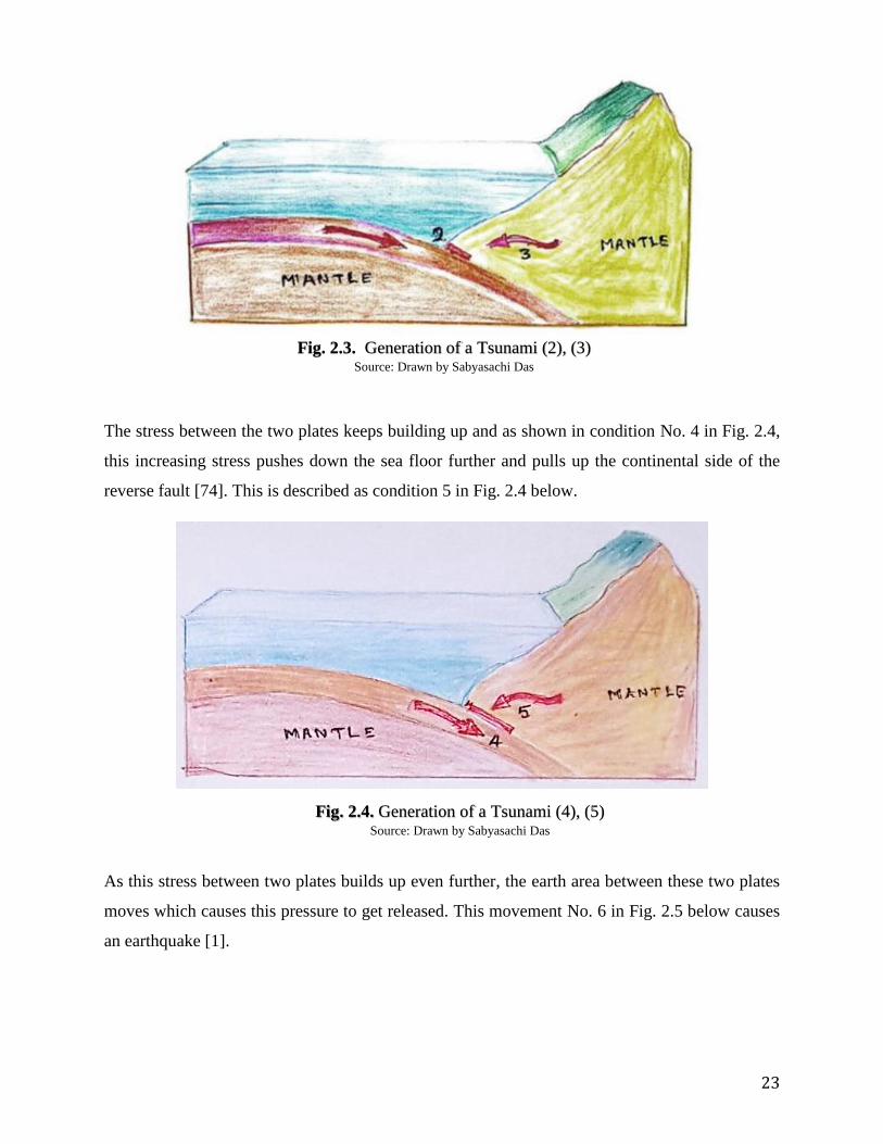
The stress between the two plates keeps building up and as shown in condition No. 4 in Fig. 2.4,
this increasing stress pushes down the sea floor further and pulls up the continental side of the
reverse fault [74]. This is described as condition 5 in Fig. 2.4 below.
As this stress between two plates builds up even further, the earth area between these two plates
moves which causes this pressure to get released. This movement No. 6 in Fig. 2.5 below causes
an earthquake [1].
Fig. 2.4. Generation of a Tsunami (4), (5) Source: Drawn by Sabyasachi Das
Fig. 2.3. Generation of a Tsunami (2), (3) Source: Drawn by Sabyasachi Das

24
As the earthquake causes the earth to rise up, as shown in No. 8 in Fig. 2.5, in turn lifts up the
water column that lies above the fault. The continental side bump of the reverse fault on the other
hand subsides. This represented as No. 8 in Fig. 2.5. This dipping of the continental plate pushes
down the water column which is depicted as No. 9 in Fig. 2.5. This phenomenon is deceiving
and often people venture farther into the sea endangering them as when the tsunami waves’ crest
approaches these people find it difficult to escape.
Now, as the water tries to return to a mutual level, it leads to formation of a series of waves of
different heights, from the origin of the earthquake through the column of water [1]. These
waves constitute the Tsunami. The higher is the depth of the water, higher is the wavelength of
the waves and the faster they move.
As Tsunami waves enter shallow water, their velocity reduces and height increases. No. 10 in
Fig. 2.6 depicts this phenomenon. When these waves reach the seashore, they might look like
briskly falling or rising tides. It is not essential that the first wave would be the largest in the
series of waves that comprise the Tsunami.
Reefs, bays, undersea features and the slope of the beach all contribute to the modification of the
tsunami as it approaches the shore. A particular coastal area may have lesser damaging wave
activity compared to other areas where destructive waves can be large and violent. Fig 2.7 shows
the map of India with earthquake prone zones [50].
Fig. 2.5. Generation of a Tsunami (6), (7), (8), (9) Source: Drawn by Sabyasachi Das

25
Like the north eastern part of India, Andaman and Nicobar Islands also come under Zone V [50].
The islands are classified to be in the most intense seismic zone among them, increasing the
possibility of a reoccurrence of an earthquake in the near future. A reoccurrence of an earthquake
in the region may trigger a tsunami considering these islands are surrounded by the Bay of
Bengal and also near the Indian ocean. Fig. 2.7 below shows the seismic map of India where the
country is classified in four seismic zones.
Fig. 2.6. Generation of a Tsunami (10) Source: Drawn by Sabyasachi Das
Fig. 2.7. Seismic Zones in India
Source: National Institute of Disaster Management

26
2.1.2. Characteristics of Tsunamis
Tsunami is comprised of a series of waves. Characteristics of Tsunamis are described below:
Cause: Tsunami waves differ from regular tidal waves which are caused due to factors like
gravitational force of moon and other celestial bodies. Tsunami waves are causes due to factors
like earthquakes, volcano etc. [77].
Water Movement: As explained section 2.1.1 above, water that forms Tsunami waves may
move to seafloor as well unlike regular waves which stay only around ocean surface.
Wavelength and Time Period: Tsunami waves have long wavelengths with values going
upwards of 100 km [75], which is much longer than wavelengths of regular waves like wind
driven ones whose wavelengths may be around 100-200m. The time waves have time periods
ranging from 10 minutes to 2 hours while wind driven waves have time periods of around 5-20
seconds [76]. This makes Tsunami waves comparatively way more destructive. That means that
these waves be this much time apart.
Impact of water depth on wave size: As distance to land decreases, size of tsunami waves
magnifies. As a result, these waves that are generated in deep ocean may often go unobserved by
vessels in the sea due to their small size on water surface. What actually happens is that the
major chunk of the wave remains below the ocean surface and the rest in above it.
Consequentially, when the wave reaches shallow region of the ocean its size increases with the
wavelength getting decreased and height increasing [1].
Velocity: While regular waves have speeds around 55mph, the Tsunami waves on the other hand
travel at speeds up to 590 mph making them comparable to jetplanes [76].
27
Energy: Tsunami can retain their energy while travelling and can therefore ravel across entire
oceans [55].
Path: The direction of Tsunami waves is like radiation from the source. Their path is
unsymmetrical and is affected by factors like extent of earthquake, the alignment of the
“subduction zone” where the earthquake is born, among others.
Severity: The size of the Tsunami waves decides its impacts. Small sized Tsunamis cause
impact to only small extent like affecting swimmers, or stationery boats, or inundating land to a
small extent. Large Tsunamis can cause devastating impacts like the 2004 Indian Ocean Tsunami
or the Japan Tsunami of year 2011.
2.1.3. Impacts of tsunami
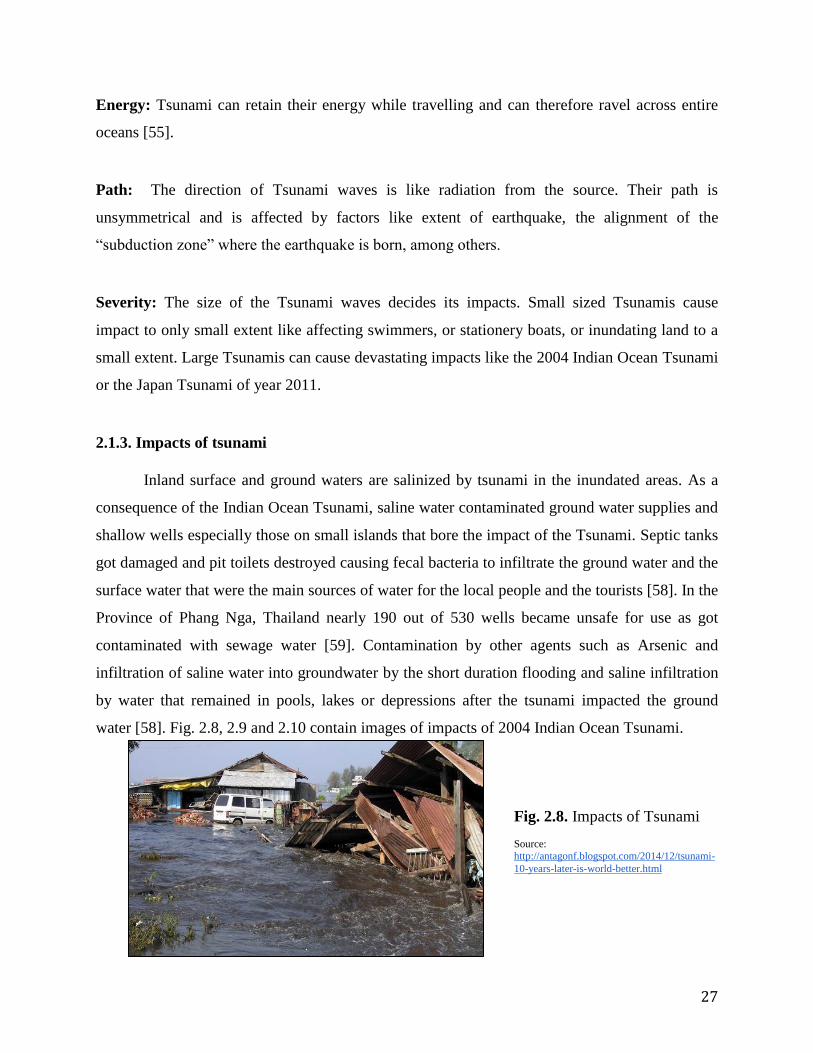
Inland surface and ground waters are salinized by tsunami in the inundated areas. As a
consequence of the Indian Ocean Tsunami, saline water contaminated ground water supplies and
shallow wells especially those on small islands that bore the impact of the Tsunami. Septic tanks
got damaged and pit toilets destroyed causing fecal bacteria to infiltrate the ground water and the
surface water that were the main sources of water for the local people and the tourists [58]. In the
Province of Phang Nga, Thailand nearly 190 out of 530 wells became unsafe for use as got
contaminated with sewage water [59]. Contamination by other agents such as Arsenic and
infiltration of saline water into groundwater by the short duration flooding and saline infiltration
by water that remained in pools, lakes or depressions after the tsunami impacted the ground
water [58]. Fig. 2.8, 2.9 and 2.10 contain images of impacts of 2004 Indian Ocean Tsunami.
Fig. 2.8. Impacts of Tsunami
Source: http://antagonf.blogspot.com/2014/12/tsunami-
10-years-later-is-world-better.html

28
The destruction of the beach resorts along the Andaman Sea, as well as the massive
tourist death-toll, led to a massive decrease in the tourism industry in Thailand, Sri Lanka and
Andaman Nicobar Islands. Tourism industry in these countries suffered damages in upward tune
of half billion dollars [60]. Immediately after these events, thousands of hotels, resorts and
independent business located on these small islands lost their business, as tourists were afraid to
travel to Thailand, Sri Lanka and Andaman Nicobar Islands [61]. In the months that followed
however, the Thailand government, the Sri Lankan Government and also the Indian government
with the help of investors and outside funds were able to re-open all hotels and began advertising
heavily in an attempt to lure visitors back into these tourist destinations.
Fig. 2.9 Satellite image of a
zone inundated by tsunami
water

29
Fig. 2.10. Images of Impact of Indian Ocean
Tsunami 2004, Andaman and Nicobar Islands
Source: Happyheartsfunds.org
Source: Happyheartsfunds.org
Source: http://www.scidev.net
Source: www.livemint.com
Source: http://www.ibtimes.co.in

30
2.2. Relationship between Structure Design and its resilience to Tsunami
From the study conducted so far, we understand Tsunami is a natural disaster that can
occur due to unpredictable ruptures in tectonic plates underwater. The severity of the impact of
Tsunami can be varying depending on the speed of the waves, the water depth, wave size
generated by the earthquake. A severe tsunami like the 2004 Indian Ocean Tsunami can cause
damage to structures near the shore of occurrence. The objective of this section is to develop a
better understanding of the forces that affect a building structure when it is struck by a tsunami.
This section studies the impact of the 2011 Japan tsunami which was similar in magnitude to the
2004 Indian Ocean tsunami, and the guidelines developed consequentially by the countries near
it to create structures with resilience. Hydrodynamic forces which are responsible for damage to
structures in case of inundation of water are also studied. The other two experiments studied in
this section as a part of this research were studied with the objective of gaining a better
comprehension about the forces that affect a structure during Tsunami and also response of the
structures to them.
2011 Japan Tsunami
The north-east coast of Japan was hit by a tsunami on March 11, 2011. An earthquake of
magnitude 9.0 on Richter scale which triggered the tsunami happened at a depth of 19.89 miles
under the surface of the Pacific Ocea n. The epicenter of this tsunami was at an approximate
distance of 43.49 miles in east direction of the Oshika Peninsula of Tohoku, Japan [62]. The
death toll caused by this event was 15,148. The economic damage exceeded 300 billion dollars,
making it the most expensive natural disaster ever to occur in history of mankind [78]. This
tsunami is discussed here since it was similar in nature and extent of damages to the Indian
Ocean Tsunami of December 2004, which accounted for the highest number of death toll in
history.
Even though tsunamis are commonly known in Japan, only a handful of the
infrastructures had the design codes and engineering guidelines which have the capacity to
sustain tsunami loads. The study in the regions affected by tsunamis states that the present
guidelines for building infrastructure are almost Stone Age or are obsolete in nature as they are
unable to withstand the present disaster.

31
Tsunami Resilience Design Guidelines in United States
Soon after the March 2011 Japan Tsunami disaster several measures were taken by the
United States to protect the Hawaii islands which are on the Pacific Ocean, and are close to
Japan. Tsunami Resilient design guidelines were incorporated as a measure into the building
design guidelines of the region. The current building codes and design guidelines procedures
provide for methods to calculate the tsunami design loads as a function of the tsunami wave
height and the slope of the beach.
American Society of Civil Engineers document (ASCE07/2005) gives engineers plans in
relation to the minimal load required for the design of the structural process. The document states
the use of hydrodynamic loads based on the principals of fluid mechanics [79].
In 2008, the FEMA published the procedures for Design of Structures named as FEMA
P646 for Vertical Evacuation from Tsunamis with an objective to provide procedures for
building tsunami refuge infrastructures which are competent of withstanding the ultimate forces
of tsunamis and earthquakes. The method of formation of the design guidelines are based on the
addressing of tsunami-induced loading and underlying concept of the approximation of the
hydrodynamic forces which affect coastal properties when there is an occurrence of Tsunami
[80].
Federal Emergency Management Agency’s (FEMA) publication FEMA55 Coastal
Construction Manual advises designing and constructing building of one and two storeys only.
This manual specifically addresses seismic loading and it also contains steps or procedures that
are relevant for river floods and wind wave loads. It also provides load amalgamation for some
structural parts and also gives knowledge on tsunami risk and danger [81].

32
2.2.1. Hydrodynamic Forces
According to FEMA, “Hydrodynamic forces are imposed on an object, such as a
building, by water flowing against and around it” The understanding of the elementary fluid
forces acting on a given body is important in design of offshore structures, underwater and
surface vehicles [66]. The drag-force on the body is caused by the viscous rubbing of the layers
of the fluid which adheres to the body due to the adhering property of water [67]. During the
process of adhesion, the net force of the layers of the viscous fluid converges into the adhered
body [67]. Hydrodynamic forces occur in the form of high velocity waves hitting stationary
bodies or moving bodies on the impacted shore. As the wave breaks with initial thrust on the
shore bodies and inundates the land at great pace, and then pulls back the water back to the
shore, hydrodynamic forces act against the structure creating frontal pressure and drag effect by
the bodies.
2.2.2. Experiment 1
Originally conducted by four researchers Taofiq Al-Faesly of University of Ottawa, Ioan
Nistor of University of Ottawa, Dan Palermo of York University, and Andrew Cornett of
National Research Council Canada as a part of their study Simulated Tsunami bore impact on an
onshore structure presented in 20th
Canadian Hydrotechnical Conference, this was the first
experiment that was studied in this research. The objective was to understand the velocity,
pressure and force of the tsunami waves when they reach the shore to have a better
understanding of these physical aspects of Tsunami waves while creating the proposed building
design. This experiment is explained in detail in Appendix Part: A of this document. The
experiment involved the simulation of a tsunami model and is explained below [9]. Fig. 2.11
below shows the square model details used in the experiment.
A one meter high plexiglas model was made with a metal structure and a flume was made
with two high discharge electrical pumps.
The experiment was performed under high discharge flume applying force on the
simulated structure with forces of a hydraulic bore identical to a broken tsunami
approaching land.

33
During this experiment force the following were recorded “forces and moments with a six
degrees of freedom load cell (6DOF), structural displacement, structural acceleration,
bore depth and bore velocity”
The experiment was conducted under two conditions of wet bed and dry bed conditions.
In the first stage of the experiment tests were conducted using hydraulic bores to obtain a
bore profile and the bore velocity (velocity of the discharged water which tends to gain
some velocity due to the acting gravity on the flow of water)
The high speed camera installed in the model tracked the bore front individually by frame
which was used to derive bore front velocity at multiple successive sections of the
flume’s longitudinal axis. The data obtained was used to calculate the bore velocity.
The bore velocity was also calculated using the time required for the bore to document a
particular inundation depth between two consecutive couples of wave gauges (WG).
The existing formulas for calculations of bore velocity were used to calculate theoretical
bore velocity value and compared to experimentally derived data.
In the wet bed condition the impact force was smaller than the run up force, and for dry
bed condition the impact force had the biggest magnitude in comparison to run up and quasi-
steady hydrodynamics. With the determination of the bore velocity, bore force and the bore
pressure we can determine the velocity, force and the pressure exerted by a series of waves
(Tsunami). The data collected by the said researchers in this experiment indicates a correlation
between the bore pressure, pressure and associated force of Tsunami waves. The bore force
Fig. 2.11: Square model details (side view) Source: Al Faesly et al. (2011) [9]
34
profile in the experiment demonstrated three major components of hydrodynamic force, which
are: impact, run up and quasi-steady hydrodynamics. The experiment develops a correlation
between bore velocity (m/s) and water bore height (m) and on comparison to data calculated
through FEMA55 and CCH formula it generated results similar in magnitude and trend to the
experimental data [9].
Keeping in mind these points and values, we can design as well as create a procedure to build
infrastructure which can withstand both flood as well as Tsunami’s damage to infrastructure.
This will make the houses resilient and provide better quality of shelter after and during such
damaging calamities keeping people’s lives safer.

35
2.2.3. Experiment-2
This experiment was conducted by Tiecheng Wang, Tao Meng, Hailong Zhao in Japan,
published as their study titled “Analysis of Tsunami Effect and Structural Response” in Tehnicki
vjesnik/Technical Gazette 22, no. 6 in year 2015. The purpose of studying this experiment is to
learn how to improve structural performance of the proposed design to resisting tsunami disaster
casualties and economic losses. This experiment is explained Appendix Part B of this document.
The purpose of studying this experiment in this thesis was to better understand the
magnitude and distribution of tsunami forces on a structure with mathematical simulation and
studying response of different simulated structural conditions under impact of tsunami forces.
As per the experiment’s simulation process, in order to compare the influence of tsunami
wave on a structure with and without wall on the upstream face at the bottom of the structure,
two different scenarios were simulated. In Case 1, the upstream face on the bottom floor of the
building was constructed with walls, as is shown in Fig. 2.12 (a), and in Case 2, the upstream
face on the bottom floor of the building didn’t have any walls and floors from 2 to 5 were
constructed with walls as is shown in Fig. 2.12(b) [32].
Fig. 2.12. (a) Case 1 Source: Wang et al (2015) [32]

36
In Case 2 of this experiment, since the bottom of the structure were not constructed with
upstream walls, the impact from the tsunami waves was borne by the columns on the bottom
floor. Therefore, in Case 2, the surface area of the structure impacted by Tsunami was
considerably small. Whereas on the other hand, in Case 1 due to the presence of walls that lead
to the building have larger surface area the forces left more impact in this case [32].
Fig. 2.12. (b) Case 2 Source: Shuto (1993) [32]

37
The graph of the data generated from the experiment, given in Fig. 13 above shows that
the maximum tsunami wave force impacting the structural condition in Case 2 is lesser compared
to condition of Case 1. Moreover, the occurrence time of maximum tsunami wave force on the
structure is later than that in Case 1. Considering the fact that in case 2, there is no in-filled wall
constructed on the upstream face of the bottom floor of the structure and the bearing bottom floor
has only columns, the reason that the impact from tsunami waves is comparatively lesser is
because the resistance of water passing through the columnar structure is less [32]. Hence the
structure in Case 2 is more effective in resisting tsunami waves, and also considering the fact that
people in such a structural condition would have more time to escape to the top or other higher
positions. The study of this experiment helps in contributing to the proposed resilient housing
design by guiding technical structural design factors and served as an important precedence in
development of the design.
Fig.2.13. Comparison of Tsunami Load on Case 1 vs. Case 2 Source: Wang et al (2015) [32]

38
2.3 Social Study of Andaman and Nicobar Islands
Location & Geography
The Andaman and Nicobar
Islands are located on the south-
east of mainland India. They are a
part of India that was closest to the
2004 earthquake epicenter. The
islands’ capital is Port Blair. They
consist of a thin chain of 572 scenic
rocks, islets, and islands that extend
along a north-south direction
between 14° N and 6.5° N latitude
and stretching over a narrow arc of
800 km in the south-eastern part of
the Bay of Bengal [33]. Fig. 2.14
shows location of the islands in South East Asia.
Only 36 of the said 572 islands are inhabited. These islands are grouped into two sets,
with the 10°N latitude international shipping channel running through them. The islands above
this latitude are called the Andaman Islands and those below it are called the Nicobar Islands.
Fig. 2.15 below is a map of the islands. South, North, Middle, and Little Andaman Islands are
the most populated among the Andaman islands. The most populated islands in the Nicobar
group are Car Nicobar, Great Nicobar, Katchal, and Kamorta islands. According to the 2011
census, the total population in the Andaman & Nicobar Islands is about 380,581
while in the in Census 2001 it was 356,152 [34].
Fig. 2.14. Location of Andaman and
Nicobar Islands in South East Asia Source: Internet

39
History of the islands
The islands were colonized as British India territories to Britain. During British rule in
India, the islands served primarily as a colony for criminal convicts from the Indian
subcontinent. The Cellular Jail in Port Blair was used to house the prisoners. The jail is now a
popular tourist destination and is listed by the UN as a UNESCO World Heritage Site. Since
1980s, the islands serve as an important defense base facilities for India. They play a key
position in India’s strategic role in Bay of Bengal and Malacca strait [35].
Flora
The Andaman and Nicobar Islands are a tropical rainforest which are made up of a mixed
type of flora with similarity to neighboring countries flora varieties. 2,200 varieties of flora have
been recorded in the islands with 86.2% area covered by forests. The islands have a wide variety
of flora ranging from deciduous forests, grasslands and mangroves [36]. These mangroves act as
seawalls in many of the islands thereby protecting them from erosion.
People
The indigenous people of the island are known as Andamanese - the Jarawa and
Sentinelese tribes who live in the Andaman Islands and the Nicobarese - Nicobari and the
Shompen islands who live throughout the islands [82]. The population of the indigenous people
of the islands are sparsely distributed throughout the islands. The majority of the population are
immigrants from the different states of mainland India [83].
Fig. 2.15. Map of Andaman
& Nicobar Islands Source: Incredible India, Ministry of Tourism, India

40
The official languages in the islands are Hindi and English. Bengali being the most
dominant most spoken languages with Hindi, Tamil, Telugu, Malayalam and Nicobarese as other
languages, according to the Census of India. Other minor spoken languages are Kurukh/Oraon,
Munda and Kharia. Andaman Creole Hindi is widely used as a trade language in the Andaman’s.
Agriculture
Agriculture is one of the predominant occupations of the residents of the islands [37]. A
total of 48,675 hectares of land is used for agriculture purposes. Rice is one of the most
cultivated crops in the Andaman group of islands. Coconut and arecanut are the cash crops of
Nicobar group of islands. Pulses, oilseeds, vegetables, along with tropical fruits such as mango,
banana, pineapple etc. are also grown. Spices such as pepper, clove, nutmeg and cinnamon are
cultivated in multi-tier cropping practices in the island where agriculture is practised [84].
Livelihood
The primary occupation of people residing in the islands is agriculture and fishing.
Forestry for the production of sawn wood for the use in domestic purposes is a common
occupational practice for the people. The excess timber production is sometimes exported to the
mainland. Furniture industry is also one of the livelihood sources for the people in the islands. In
recent times processed foods and garment industry are growing trades. Port Blair, an island town
and the capital of the island territories which has historic importance attracts tourists throughout
the year from mainland India and foreign countries. The other parks, sanctuaries and island
resorts on other islands help promote the growing tourism industry of the islands [85].
Housing
The indigenous people of the islands live in huts and temporary houses constructed with
bamboo, wood having thatch roofs made with materials like hay and mud. The other residents of
the islands live in one to three storey houses that have concrete construction structure and walls
with sloping metal roofs or flat concrete roofs. People belonging to lower economic strata live in
houses made using wood walls construction and tin metal roofs. These were the predominant
style of housing that people resided in when the Indian Ocean Tsunami struck in year 2004.

41
The houses occupied by the indigenous people of the islands were located at higher
elevations i.e. hilly areas on the islands and bore little or no impact of the Tsunami. Owing to the
higher elevations in the location of these houses, Tsunami waves couldn’t impact them.
The other dwellers of the islands that lived in the kind of houses described above, and
resided closer to the shoreline of the islands bore the most impact of the Tsunami getting
damaged as a result.
42
2.4. Regulatory Requirements of Government of India to inculcate Tsunami Resilience in
Structures [38]
2.4.1. Design Criteria
According to the National Institute of Disaster Management (NIDM) report “Design Criteria
for reconstruction of Houses in Tsunami affected areas in India” [68], latest construction in such
areas must consider multi-hazard climatic problems of a coastal-area and the design criteria
should consider certain aspects. These include: Wind Speed in cyclonic conditions; Continuous
wind pressure at sea coast; Height of storm with height of tide level; effects of Tsunami,
including (i) height of the tsunami wave, ii) Dynamic pressure of the tsunami waves; effects of
Earthquakes; Fire Hazards and safety; Flood flow and flood height; Building aspects like Shape,
size and height of buildings; importance of the buildings and choice of material and the
technology used to construct it.
The said NIDM report also lists certain factors that must be considered in design stage of
constructing buildings in coastal regions. These include pressure factors, seismic coefficients,
storm surge, etc. These are given as Table A.C.1 in Appendix: Part C of this thesis.
The said report also mentions the characteristics that Reinforced Concrete (RC) used in
construction in coastal areas should have. These are mentioned in Appendix: Part C.
The National Disaster Management Authority (NDMA) published a report “National Disaster
Management Guidelines: Management of Tsunamis” in year 2010 where they have given
guidelines for mitigation of impacts of Tsunami, one of which is incorporating safety in design
and construction of buildings in Tsunami prone areas. In this document, they state that impact of
hydrodynamic forces can be avoided by elevating buildings, anchoring buildings to their
foundation, and designing buildings for dynamic water forces on the walls of buildings and other
building elements [38]. The Bureau of Indian Standards has published “Draft Indian Standard
Guidelines for Risk Reduction of Structures Against Tsunami” where they have discussed design
solution for many factors. For hydrodynamic forces, they state that to evade hydrodynamic
pressures, buildings should be elevated on stilts [69].

43
One of the other draft guidelines talks about are hydrostatic forces where they state that
with the objective to allow water to be at equal elevation outside and inside buildings, adequate
openings like louvres should be provided [69]. Regarding buoyancy floatation or uplifting forces
caused due to buoyancy, the guidelines state that in order to avoid flooding arising due to such
forces, buildings should be elevated. In addition, to avoid floatation buildings should be
anchored to their foundation [69].
2.4.2. Specific Recommendations for Andaman & Nicobar Islands
2.4.2.1. Structural measures:
Since, as mentioned earlier, Andaman & Nicobar Islands fall in Seismic Zone V, the report
advises that buildings in these islands should incorporate features that make these structures
earthquake resistant. These include:
Stilts made of Steel and RC columns should be used for erection of buildings at higher
elevations from sea shore grade level. Houses should have earthquake resistance features
like anchoring of structural elements with the main structure, etc.
Use of Pre-engineered, pre-fabricated, and modular composite structures should be made
popular.
Readily available materials like hollow concrete blocks (also called CMUs), steel etc.
should be used as Transportation costs are high and demand for materials is also high.
Roofs should have feature for water harvesting.
Roofs should be sloping and should be used along with sheeting made of Galvanized Iron
(CGI)
The first floor elevation of the building should be at a minimum height of 3m above the
seashore grade.
Steel Corrosion resistance measures has to be given priority in all RC and steel
constructions

44
Houses should be able bear wind speeds of 44 m/s [68]. Housing developed for
earthquake resiliency having a ductile RC frame should have an earthquake coefficient of 0.09, R
= 5.0 [68]. Any load bearing walls in such buildings should a category D earthquake coefficient
[68]. Wall construction in these buildings should have a fire rating of 1.5 hours. For Andaman
Islands the minimum height of stilts should be at least 2m and in case of Nicobar Islands this
height should be 3m at least [68].

45
2.5. Climate Characterization
According to NASA the climate of a region or city is its typical or average weather over a
long-time order. One of the key determinant factors of climate of a region is its latitude which
controls the degree of warming [39]. The tilt of the earth’s axis is accountable for degree of
warmness at different latitudes as angle of sun rays contact varies with the latitudinal location on
earth [40].
The further the latitude is from the equator the sun rays spread broader and those latitudes
receive lesser heat [41]. The purpose of climate characterization of Andaman and Nicobar in this
study is to better understand the local climate of the region and use it as a design tool to
influence the design proposal process of the tsunami resilient house for the islands. The software
Climate consultant 6.0 has been used as a tool for climate characterization of the islands. Data
for Chennai, India which is the closest city in mainland India to these islands with very close
latitudinal proximity of 13.0827° N compared to Andaman and Nicobar Islands 11.7401° N was
used for the Climate Characterization. Chennai’s close proximity to the islands and the
originating epicentre led it to suffer massive damage due the Tsunami in 2004. It is assumed the
islands are in the similar latitudinal zone as Chennai and the availability of Chennai’s weather
data allows proper running of the software to determine the regions climatic conditions.
Fig. 2.16. Monthly Diurnal Averages. Source: Climate Consultant 6.0

46
ASHRAE Standard 55 has been used as a basis of comfort levels in generating the data through
the Climate consultant 6.0 Software.
The Monthly Diurnal Averages shown as Fig.16 above show temperatures in the zone as
mostly constant throughout the year with an annual average of 90°F. The temperature range as
per the figure refers to it mostly above the comfort zone. In general, the climate is constantly
humid through the year as the dry bulb and the wet bulb temperature maintain a similar average
relation as per the figure. The precipitation during the winter months is emphasized by the dry
bulb temperature being closer to the wet bulb temperature. The climate maintains a fairly high
constant amount of global horizontal radiation throughout the year. The wind in the zone is
distributed in almost all directions, however prevailing winds come from the Southern direction
from the Indian ocean below towards North in the Bay of Bengal which is shown in the wind
wheel given in Fig. 2.17.
The psychrometric chart in Fig. 2.18 shows that climate in the zone is in the comfort zone
as per ASHRAE Standard 55-2010 for only 0.7% of the hours of the year. The data are
concentrated highly on the upper part of the graph in the figure where the weather is too hot and
humid for comfort standards. The main passive design strategies that can be applied for the
islands in this zone are sun shading of windows to reduce the effect of the constant amount of
global horizontal radiation and oriented towards prevailing breezes for cooling, good cooling
systems, features can regulate the high temperatures, and good natural ventilation could improve
dehumidification. The Sun Shading Chart in Fig. 2.19. is for the summer months, it shows that
considering the zones radiation if a shade is oriented at an angle of 30° it will be successful in
creating proper shade to the opening throughout the day for the seasonal period.

47
Fig. 2.17.
Wind Wheel. Source: Climate
Consultant 6.0
Fig. 2.18. Psychrometric Chart Source: Climate Consultant 6.0

48
2.6. Analysis and Strategies
The study of Experiment 1 gives us an in-depth knowledge about the forces that are
responsible for the impact of a Tsunami on life and property. It also sheds light on velocity, force
and the pressure exerted by the Tsunami waves, a study of which was essential owing to the fact
that a building’s shell design adds to its endurance capacity. The study of Experiment 2 also
gives us a better understanding of the magnitude and distribution of tsunami forces on a
building’s structure through case studies of simulated structural conditions under similar impact
of tsunami forces. The results of the experiment suggest that buildings with no infill walls on the
upstream face of the bottom floor of the structure will suffer impact of much lesser magnitude
compared to buildings with walls in the lower level. When no infilled wall is constructed in the
bottom floor and there are only columns on the bottom floor bearing the impact from tsunami
Fig.2.19. Sun Shading Chart Source: Climate Consultant 6.0

49
waves, the endurance of the building to passing water is smaller. This also allows people in the
building more time to escape to the top or other areas as higher elevations.
The culture and history of the island shows that the island is inhabited by people from a
mix of regional and cultural backgrounds from all over mainland India giving the islands a mix
Indian cultural identity.
The housing system in the island has sloped gable roof in reinforced concrete (RC)
construction or wood construction being the most predominant styles.
The National Institute of Disaster Management (NIDM) recommends that the
performance of buildings having a circular shaped structure increases its resilience during a
Tsunami as water is able to easily flow around [42].
The impact of damage on the houses constructed with RC was large even though they
were new permanent constructions, as they didn’t involve any seismic code in their design. So
these houses couldn’t withstand the tsunami’s seismic force impact [4]. The traditional wood
houses and even old masonry structures on the island survived better in response to the ground
shaking [4]. The recently constructed RC housing and buildings which didn’t have ductile
detailing in their column construction didn’t survive the tsunami well compared to the ones that
did have them in their columns [4]. In response to the zoning of the coastal area of the islands,
the law of the land now requires that all new permanent settlements should be located a
minimum of 10 meters above contour levels or 3 meters above high tide line, whichever is higher
to prevent inundation of water near the seashore area. The roofs are recommended to be sloping
in nature.
As discussed in the design guidelines in Tsunami affected areas, the design criteria for
infrastructure in the zone should keep the hazardous climatic conditions in mind. Along with
continuous wind pressure along the coast, the height of tide levels should be considered [43].
The guidelines also advise that dynamic pressure of waves should be factored in structural
calculation, as discussed above in reference to the experiment. Building aspects such as shape,
size and height of buildings should be aptly decided in relation to location of the building near
the coast line.

50
According to the Indian government’s design guidelines, following should be followed
for housing buildings in Andaman and Nicobar islands: Wind speed - 44m/s; Factor of Pressure
K1-1.0, K2-1.05, K3- 1.00; Fire Safety- 1.5 hr rating; Earthquake coefficient: Ductile RC Frame-
0.09 (R=5.0), Load Bearing Wall Building- Cat. D. The guidelines also recommends that houses
be built on stilts with RC/steel columns having features that make them earthquake resistant.
They also emphasize on use of prefabricated, pre-engineered and modular structural composite
structures.
In climate characterization of the region, it was found that the region is hot and humid in nature
with constant amount of direct horizontal radiation on the islands. The wind prevails more from
the Indian Ocean lying below them and towards the North in the Bay of Bengal. Owing to the
fact that these islands are in a zone where the climate is in comfort levels in only 0.7% of the
hours of an year, it is important that passive techniques of cooling and ventilation are integrated
in design of these Tsunami resilient housing for human comfort. As having substantial comfort
levels will allow the houses to be better habitable during the period of residence. Since disasters
comes once in a while in a region but along with human lives safety through them we need to
keep in mind about the long-term viability of the usage of the space during the users residency
period.

51
PART 3: APPLICATION OF STRATEGIES

52
3.0 APPLICATION OF STRATEGIES - CONCEPT DESIGN
The study of the methods and the analysis of the information obtained contributed to the
development of the concept design which is illustrated below. Refer Figure 3.9 for 3D
Perspective view of proposed design.
3.1. Building Mass and Form
Process Study: During the process study various forms were studied before the development of
form as per Fig. 3.1. The analysis was applied in developing the options and based on the facts of
impact of tsunami forces and economic viability they were evaluated. Option one is viable in
terms of the angular impact of forces but they are only case specific to conditions if the tsunami
comes in a particular orientation. The option two stepping of the faced was helping in breaking
the waves but at the same point of time the center portion would be substantially weak due to the
deep step in the impact forces will be concentric. The third option of a regular circular building
helps to solve impact issues as water can glide along it and move in a fluid manner but it is not
economically viable to construct round permanent houses as circular construction is
comparatively expensive and also leads to loss of usable interior area. The fourth option was
chosen and is described in detail below. It was designed with a balance between force and
economic factors.
Fig. 3.1 Process Study sketches Source: Drawn by Sabyasachi Das

53
The elevation of the building facing the seaward or coastal side is shaped as an arched
wall. The hydrostatic forces from waves of the tsunami when acting on a flat surface, for
example as in the Figure 3.2 (a) below tends to apply their total concentrated vertical load on it
as the acting forces don’t have any horizontal component. In case of a curved wall as in the case
in Figure 3.2 (b), the hydrostatic forces acting on a curved wall surface tend to have distribution
of forces along the surface as there is proportionate magnitude of both horizontal and vertical
force components in the condition and there is dissipation of force energy in the process [44].
The proposed building mass widens from the coastal facing end towards the inland side to create
a tapering affect.
Water moves by the method of adhesion to a surface. The widening of the mass towards
the land allows the water to glide along it and widens the direction of waves hitting the building.
This would help in reducing the intensity of the waves reaching the area behind the building. The
developed mass is made symmetrical in construction to promote proper binding of the unit.
The developed form has nautical feature to act in simulation of a boat in water. This would allow
the building to survive through a flash tsunami wave condition as well as its fluidic shape will
Fig. 3.2 (a) Building Mass & Form
in a rectangular house Source: Drawn by Sabyasachi Das
Fig. 3.2 (b) Building Mass & Form
in proposed design Source: Drawn by Sabyasachi Das

54
allow for better survival through a wind storm. The seaward façade of the house has a
combination of convex and concave arcs in consideration of the fact that tsunami waves are
unpredictable in path. Smaller arcs will increase the chance of dissipation of energy of the waves
from the different directions. A larger single convex arced façade would also have dissipation of
energy but as it would be a relatively larger arc it would also have longer linear tangents
compared to the proposed case with multiple arcs. An increase in the amount of possible linear
tangent would also increase the effect of vertical forces depending on the direction of the wave
but lesser compared to a flat wall under given conditions. In development of this form economic
aspects have been also kept in mind, as the vision is to also make it economical to a higher mass
of people and bring safety to their lives. The seaward sides façade with multiple arcs allows
easier buildability as circular construction or arced construction is relatively more expensive than
regular straight wall constructions. Therefore, in consideration of the fact that Tsunami would
come from the sea ward side of the island towards which this house is oriented only the seaward
side is shaped so and the lands’ end is more functionally made of regular linear walls. The waves
after the impact on the front façade of the building reduce in height and inundates into the land.
The height of the waves generally reduces on the way backward but do carry debris with them
which can flow thought the open space below.
In consideration of the fact that housing in islands are clustered along the coast it is important
that this proposed design acts in a model cluster along the coast with one side of the houses
facing seaward.
The proposed design is repeated as blocks and analyzed in context. The elevation with the arced
walls are oriented the sea. As waves approach the shore the water would flow though the set of
houses or through below them as it inundates into the land. On the way backward from the land
toward the sea the water level heights being lesser comparatively to the impact waves can flow
through the buildings. The figure 3.3 below represents the same.

55
Fig. 3.3. Source: Drawn by Sabyasachi Das
3.2. Columns
Based on the recommendations of the analysis, the proposed design is to be made at a
plinth height of at least 3 meters. Circular columns are proposed in the design considering the
fact they have higher resistance to bending or deflection compared to a square column of the
same cross section area [45]. Circular columns are symmetrical in nature about any centroidal
axis. Their characteristic omnidirectional strength under influence of seismic and wind loads
have made them popular for use in bridge pier design. Refer to Figure 3.5.
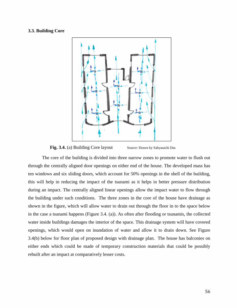
56
Fig. 3.4. (a) Building Core layout Source: Drawn by Sabyasachi Das
3.3. Building Core
The core of the building is divided into three narrow zones to promote water to flush out
through the centrally aligned door openings on either end of the house. The developed mass has
ten windows and six sliding doors, which account for 50% openings in the shell of the building,
this will help in reducing the impact of the tsunami as it helps in better pressure distribution
during an impact. The centrally aligned linear openings allow the impact water to flow through
the building under such conditions. The three zones in the core of the house have drainage as
shown in the figure, which will allow water to drain out through the floor in to the space below
in the case a tsunami happens (Figure 3.4. (a)). As often after flooding or tsunamis, the collected
water inside buildings damages the interior of the space. This drainage system will have covered
openings, which would open on inundation of water and allow it to drain down. See Figure
3.4(b) below for floor plan of proposed design with drainage plan. The house has balconies on
either ends which could be made of temporary construction materials that could be possibly
rebuilt after an impact at comparatively lesser costs.

57
3.4. Lateral Support
In reference to the literature review about the benefits of concentrically braced
connections for dual purpose of damage control and prevention of structural collapse, steel rods
of circular shape are used as cross bracing in between the columns to provide lateral support.
This lateral support system will allow the structure to resist the impact when waves of Tsunami
move from the coast towards the land through this building as well as when the water travels
back to the sea after the flash flooding has happened. Refer Figure 3.5 below.
Fig. 3.4. (b) Floor Plan of Proposed Design with drainage plan Source: Drawn using Revit 17 by Sabyasachi Das

58
3.5. Cooling and Ventilation
As discussed earlier, Andaman and Nicobar Islands have a hot and humid climate
throughout the year, and cooling is mostly required to provide comfortable conditions. Passive
cooling methods are applied in the proposed design. The core of the building being narrow with
centrally aligned openings along with benefits from impact of tsunami also acts as cross
ventilation for the designed house in principal application of the Bernoulli effect. The figures 3.6
(a) and 3.6 (b) below shows the cross ventilation of air through the building and are precedent
sketches. Figures 3.6 (c) and 3.6 (d) below represent the application of strategies based on the
precedence of sketches as above. High roofs and stack ventilation technique has been used to
promote process of ventilation and dehumidification of the spaces. Figure 3.6 (d) represents the
same.
Fig. 3.5. Building Section
Source: Drawn using Revit 17 by Sabyasachi Das

59
Fig. 3.6 (a) Airflow Source: Drawn by Sabyasachi Das
Fig. 3.6 (b) Airflow Source: Drawn by Sabyasachi Das

60
3.6. Roofing and Shading
The seaward facing of the building which has curved walls have an extending shade from
the roof created by bamboo which is an available material in the region. This helps in shading of
the balcony as evident from the Climate consultant tool that there is constant distribution of
global horizontal radiation throughout the year. This bamboo shade which is made of a relatively
temporary material as they are easily available also has a combing effect to the impact waves.
And after impacts they could be easily replaced. Similarly, in the land end of the building there is
a gazebo like structure over the stairs near the entrance created by a grid of bamboo to give
shading. The proposed design has two roofs which are sloping in nature and is in combination
with stacked ventilation to allow proper movement of air. As per the sun shading chart generated
by the climate consultant software tool, the shades for the windows have been oriented at a 30-
Fig. 3.6 (d) Ventilation Cooling Source: Drawn by Sabyasachi Das
Fig. 3.6 (c) Application of Bernoulli effect
via narrow core layouts Source: Drawn by Sabyasachi Das

61
degree angle to provide optimum shade throughout the day in the warmer summer season and
allowing better comfort to the users of the building. Refer Fig. 3.7. below.
Fig. 3.7. Roof Plan Source: Drawn using Revit 17 by Sabyasachi Das

62
3.7. Suggested materials for Proposed Design:
The materials suggested are based on their easy availability in the area. For the exterior
and interior walls hollow CMU blocks are suggested. These CMU blocks are easily available in
the region as well as have high compressive strengths compared to conventional bricks. The
hollow CMU block also helps in cooling and breathability of the building as it has air in between
them and will allow the building to cool off in the evenings [65]. Even though hollow concrete
blocks are lighter in comparison to regular brick or solid CMU there is always a chance of them
getting cracked with the impact of a tsunami. This CMU blocks being a cheap construction
material in the region will allow the easy replacement of them in such events when a particular
portion of the building gets damaged. The circular columns are suggested to be made of
reinforced concrete construction with earthquake resistant ductile detailing in them. The lateral
bracings connected to them are circular steel rods with anti-rust protection coating. This lateral
bracing is to be installed in between the columns as in Fig.3.8 (b).
The installed windows and doors are hurricane rated. Since in India there isn’t any available
storm rating system yet, but major companies do sell hurricane rated windows and doors which
can resist winds up to 125mph. The shading features in the sea facing and the land facing end are
made of bamboo which is cheap and available in the region. Bamboo being a tensile material
will be able to better withstand the first impact forces on the face of the building. And in case of
their damage it is comparatively inexpensive to rebuild using bamboo. The stairs are to be made
of steel and connected well to the foundation. So that in event of a tsunami the stair steel
structure is retained in place as the inundated water goes back to the sea. The roofing material is
suggested to be made of industrial metal decking system which is also available commercially as
an import material to the area. Metal decking is long lasting and lighter in comparison to
concrete roof systems and easier to install. Metal decking is imported into the island by various
manufacturers for other commercial purposes. The proposed stack ventilation systems for better
cooling comfort in the building are generally made of aluminum. The floor area inside the house
is suggested to be made of concrete cast in place. The balconies which are added features to this
resilient design for human comfort can be made of cheaper wood construction which could be
replaced even if they get damaged by an event of a tsunami.

63
Fig. 3.8. (a) Sea Facing Elevation Source: Drawn using Revit 17 by Sabyasachi Das
Fig. 3.8. (b) Side Elevation Source: Drawn using Revit 17 by Sabyasachi Das

64
Fig. 3.8. (c) Land-end Elevation Source: Drawn using Revit 17 by Sabyasachi Das
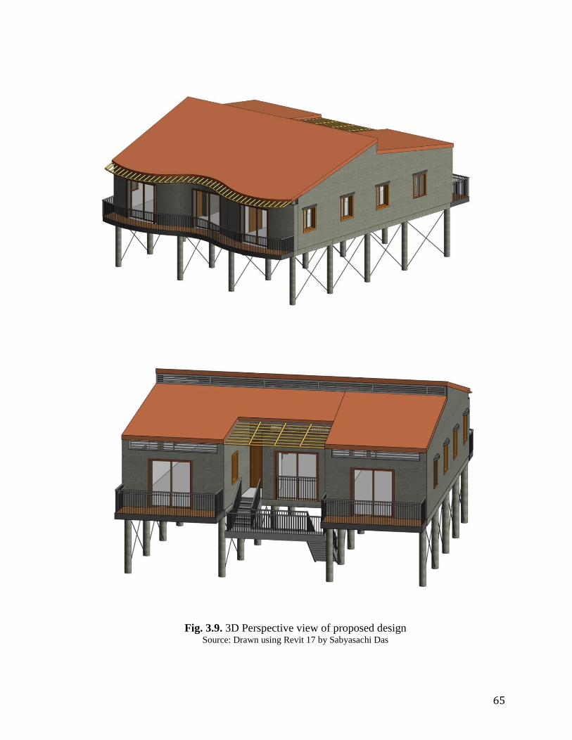
65
Fig. 3.9. 3D Perspective view of proposed design Source: Drawn using Revit 17 by Sabyasachi Das

66
3.8. Cost of Construction of Proposed Design
The area of the proposed house design is 1500 sqft. The total estimated material cost of
making this building is 14,180 USD (Rs. 9,50,000). This excludes land costs and interior
development .
The cost of the foundation is 2,238 USD (Rs 1,50,000)and structural costs is 5970 USD (Rs
4,00,000) .The cost of the building the core and shell of the proposed design with walls is 2985
USD (Rs 2,00,000). Doors, windows, roofing and other wood work is estimated to cost 2985
USD (2,00,000). The estimation of cost of making this house in Andaman and Nicobar Islands
is made in consideration of I materials market and construction service costs in India.( Note: 1
USD= 67 Rupees)

67
3.9. Psychrometric Results on application of Passive techniques
On application of the passive design techniques of sun shading, ventilation and
dehumidification methods there is an increase in the comfort levels in the proposed design from
the baseline condition of the region which only has 0.7% comfort levels. The increased comfort
levels as per the chart is 29.2%.
Fig.3.10. Psychrometric Chart Source: Climate Consultant 6.0

68
3.10. Thesis Way Forward
In the way forward a detailed structural calculation can be done in addition to the
research to properly size the structural elements based on the loads.
A simulation of the proposed design could be done in fluid tunnels
Actual development of the prototype in the islands

69
PART 4: CONCLUSION

70
4.0 CONCLUSION
With a growing trend of human settlement along the coastal areas, more fraction of the
population is getting vulnerable to natural disasters caused by climate change and tectonic shifts
in the coastal regions with flooding, storms and Tsunamis being the primary forms of natural
disasters hitting these regions. Resilient housing is a proposed solution to reduce the loss of
housing post disaster and to protect human lives during the course of a disaster. This thesis
discussed in depth about the natural disaster caused by the Indian Ocean Tsunami, 2004 with the
Andaman and Nicobar Islands, India, as a case study to understand the characteristics and
impacts of tsunami through a literature study driven approach with the objective to create a
resilient design prototype based on the methodology of investigation and evaluation of strategies
in the research.
Keeping in perspective the words of the NOAA “achieving resilience requires
understanding environmental threats and vulnerabilities to combat issues like sea level rise” this
thesis research work started with the understanding of Tsunami as a form of natural disaster and
its forces which affects the structures in affected area. This research has developed a design
prototype with resilient features which could be adapted by people in the area to create better
resilient housing for protection of their lives from future disasters. The features of the proposed
design can also be used as retrofitting techniques in the existing houses in the region.
Being able to create and dwell in resilient houses makes its users stewards of
sustainability as they are being socially, economically and environmentally responsible. This
approach could also be possibly used by people around the world in areas which are prone to
Tsunami or by other coastal natural calamities to create resilient housing in areas where the
climatic conditions are similar. In regions that have different climate, different materials and
construction methods specific to the location may be applied.

71
BIBLIOGRAPHY
[1] The Tsunami Story, NOAA. http://www.tsunami.noaa.gov/tsunami_story.html (Last
accessed on November 2, 2017)
[2] Lay, Thorne, et al. "The great Sumatra-Andaman earthquake of 26 december 2004."
Science 308.5725 (2005): 1127-1133.
[3] Social and Economic Impact of December 2004 Tsunami, Asia Disaster Preparedness
center.
http://cmsdata.iucn.org/downloads/social_and_economic_impact_of_december_2004_tsu
nami_apdc.pdf (Last accessed on October 31, 2017)
[4] Maheshwari, B. K., M. L. Sharma, and J. P. Narayan. "Geotechnical and structural
damage in Tamil Nadu, India, from the December 2004 Indian Ocean tsunami."
Earthquake Spectra 22.S3 (2006): 475-493..
[5] NOAA: ‘Nuisance flooding’ an increasing problem as coastal sea levels rise.
http://www.noaanews.noaa.gov/stories2014/20140728_nuisanceflooding.html (Last
accessed on November 2, 2017)
[6] Koh, Hock Lye, et al. "Earthquake and tsunami research in USM: The role of Disaster
Research Nexus." Pertanika J Sci Technol 20.1 (2012): 151-163.
[7] El-Masri, Souheil, and Graham Tipple. "Natural disaster, mitigation and sustainability:
the case of developing countries." International planning studies 7.2 (2002): 157-175.
[8] Mayunga, Joseph S. "Understanding and applying the concept of community disaster
resilience: a capital-based approach." Summer academy for social vulnerability and
resilience building 1 (2007): 16.
[9] Al-Faesly, Taofiq, et al. "Simulated tsunami bore impact on an onshore structure." 20th
Canadian Hydrotechnical Conference. 2011.
[10] Folke, Carl, et al. "Resilience and sustainable development: building adaptive capacity in
a world of transformations." AMBIO: A journal of the human environment 31.5 (2002):
437-440.
[11] Adger, W. Neil, et al. "Social-ecological resilience to coastal disasters." Science 309.5737
(2005): 1036-1039.
[12] Cannon, Terry. "Vulnerability analysis and the explanation of ‘natural’disasters."
Disasters, development and environment (1994): 13-30.

72
[13] Schilderman, Theo. "Adapting traditional shelter for disaster mitigation and
reconstruction: experiences with community-based approaches." Building Research &
Information 32.5 (2004): 414-426.
[14] Basabe, Pedro. "Hyogo Framework for Action 2005–2015." Encyclopedia of Natural
Hazards. Springer Netherlands, 2013. 508-516.
[15] Bosher, Lee, and Andrew Dainty. "Disaster risk reduction and ‘built‐in’resilience:
towards overarching principles for construction practice." Disasters 35.1 (2011): 1-18.
[16] Burton, Ian. The environment as hazard. Guilford Press, 1993.
[17] Shaw, Rajib, and IEDM Team. "Climate disaster resilience: focus on coastal urban cities
in Asia." asian Journal of environment and disaster Management 1 (2009): 101-116.
[18] Lang, Heracles. "Community housing in post disaster area on Nias islands, Indonesia:
responding to community needs." Proceedings of the 4th international i-Rec conference,
University of Canterbury, Christchurch. 2008.
[19] Murty, C. V. R., Durgesh C. Rai, Sudhir K. Jain, Hemant B. Kaushik, Goutam Mondal,
and Suresh R. Dash. "Performance of structures in the Andaman and Nicobar Islands
(India) during the December 2004 great Sumatra earthquake and Indian Ocean tsunami."
Earthquake spectra 22, no. S3 (2006): 321-354.
[20] Reddy, BV Venkatarama. "Sustainable building technologies." Current Science (2004):
899-907.
[21] Taylor, John R. "Light transmitting roof/floor system." U.S. Patent 5,715,636, issued
February 10, 1998.
[22] Lukkunaprasit, Panitan, and Anat Ruangrassamee. "Building damage in Thailand in the
2004 Indian Ocean tsunami and clues for tsunami-resistant design." The IES Journal Part
A: Civil & Structural Engineering 1, no. 1 (2008): 17-30.
[23] Yeh, Harry Hsiu-jen, Ian Robertson, and Jane Preuss. Development of design guidelines
for structures that serve as tsunami vertical evacuation sites. Vol. 4. Washington State
Department of Natural Resources, Division of Geology and Earth Resources, 2005.
[24] Lukkunaprasit, P., A. Ruangrassamee, and N. Thanasisathit. "Tsunami loading on
buildings with openings." Science of Tsunami Hazards 28, no. 5 (2009): 303.

73
[25] Bosher, Lee, Andrew Dainty, Patricia Carrillo, and Jacqueline Glass. "Built-in resilience
to disasters: a pre-emptive approach." Engineering, Construction and Architectural
Management 14, no. 5 (2007): 434-446.
[26] Alam, Edris, and Andrew E. Collins. "Cyclone disaster vulnerability and response
experiences in coastal Bangladesh." Disasters 34, no. 4 (2010): 931-954.
[27] Pacheco, Kason Hoku. Evaluation of tsunami loads and their effect on reinforced
concrete buildings. Diss. 2005.
[28] Gautam, Dipendra, et al. "Disaster resilient vernacular housing technology in Nepal."
Geoenvironmental Disasters 3.1 (2016): 1.
[29] Yeh, Harry, et al. "Tsunami loadings on structures: Review and analysis." Coastal
Engineering Proceedings 1.34 (2014): 4.
[30] Mayes, R. L., A. G. Brown, and Dario Pietra. "Using seismic isolation and energy
dissipation to create earthquake-resilient buildings." Bulletin of the New Zealand Society
for Earthquake Engineering 45.3 (2012): 117-122.
[31] Fitzgerald, T. F., et al. "Slotted bolted connections in aseismic design for concentrically
braced connections." Earthquake Spectra 5.2 (1989): 383-391.
[32] Wang, Tiecheng, Tao Meng, and Hailong Zhao. "ANALYSIS OF TSUNAMI EFFECT
AND STRUCTURAL RESPONSE." Tehnicki vjesnik/Technical Gazette 22.6 (2015).
[33] About Andamans. http://www.andamans.gov.in/html/andamans.html. (Last accessed on
October 27, 2017)
[34] Census of India,2011. http://censusindia.gov.in/. (Last accessed on October 27, 2017)
[35] Mathur, Laxman Prasad. "History of the Andaman and Nicobar Islands 1756 to 1947."
(1959).
[36] Hajra, Parbhat Kumar, P. S. N. Rao, and V. Mudgal. "Flora of Andaman & Nicobar
Islands." (1999).
[37] Temple, Richard Carnac. Andaman and Nicobar Islands. Asian Educational Services,
1994.
[38] National Disaster Management Authority Government of India. National Disaster
Management Guidelines, Management of tsunamis. New Delhi: National Disaster
Management Authority Government of India, 2010.

74
http://www.ndma.gov.in/images/guidelines/ndmaguidelinesmanagementofsunamis.pdf
(Last accessed on October 31, 2017)
[39] What are climate and climate changes. https://www.nasa.gov/audience/forstudents/5-
8/features/nasa-knows/what-is-climate-change-58.html. (Last accessed on October 31,
2017)
[40] Latitude and climate zones. https://enviroliteracy.org/air-climate-
weather/climate/latitude-climate-zones/. (Last accessed on October 31, 2017)
[41] Deutsch, Curtis A., et al. "Impacts of climate warming on terrestrial ectotherms across
latitude." Proceedings of the National Academy of Sciences 105.18 (2008): 6668-6672.
[42] PERMANENT SETTLEMENTS IN ANDAMAN & NICOBAR ISLANDS.
http://nidm.gov.in/idmc/Proceedings/Cyclone%20&%20Tsunami/B4-
14%20Rahul%20Burman.pdf ( Last accessed on October 25,2017)
[43] NOAA: ‘Nuisance flooding’ an increasing problem as coastal sea levels rise, July 28,
2014. http://www.noaanews.noaa.gov/stories2014/20140728_nuisanceflooding.html
(Last accessed on October 25,2017)
[44] Roth, R., B. Götzelmann, and S. Dietrich. "Depletion forces near curved surfaces."
Physical review letters 83.2 (1999): 448.
[45] Priestley, MJ Nigel, Ravindra Verma, and Yan Xiao. "Seismic shear strength of
reinforced concrete columns." Journal of structural engineering 120.8 (1994): 2310-
2329.
[46] Werner, Adrian D., and Craig T. Simmons. "Impact of sea‐level rise on sea water
intrusion in coastal aquifers." Groundwater 47.2 (2009): 197-204.
[47] How much water is there on, in, and above the Earth?.
https://water.usgs.gov/edu/earthhowmuch.html. (Last accessed on November 11, 2017)
[48] Fukuji, Tammy. What is a Tsunami? - International Tsunami Information Center.
http://itic.iocunesco.org/index.php?option=com_content&view=article&id=1162%3Awh
at-is-a-tsunami&catid=1340&Itemid=2056.( Accessed November 11, 2017).

75
[49] Shuto, N. "Tsunami intensity and disasters." Tsunamis in the World. Springer Netherlands,
1993. 197-216.
[50] Malik, Javed N., C. V. R. Murty, and Durgesh C. Rai. "Landscape changes in the Andaman
and Nicobar Islands (India) after the December 2004 great Sumatra earthquake and
Indian Ocean tsunami." Earthquake Spectra 22.S3 (2006): 43-66.
[51] Resilient Design. http://www.resilientdesign.org. (Last accessed on November 9, 2017)
[52] Tsunami Generation from the 2004 M=9.1 Sumatra-Andaman
Earthquake.https://walrus.wr.usgs.gov/tsunami/sumatraEQ/tectonics.html
(Last accessed on November 4, 2017)
[53] Tanioka, Yuichiro, et al. "Rupture process of the 2004 great Sumatra-Andaman earthquake
estimated from tsunami waveforms." Earth, planets and space 58.2 (2006): 203-209.
[54] WARD, Steven N. "Relationships of tsunami generation and an earthquake source." Journal
of Physics of the Earth 28.5 (1980): 441-474.
[55] Van Dorn, William G. "Tsunamis." Contemporary Physics 9.2 (1968): 145-164.
[56] Wu, Theodore Y. "Long waves in ocean and coastal waters." Journal of Engineering
Mechanics 107.EM3 (1981): 501-522.
[57] Ammon, Charles J., et al. "The 17 July 2006 Java tsunami earthquake." Geophysical
Research Letters 33.24 (2006).
[58] Rodriguez, Havidan, et al. "A snapshot of the 2004 Indian Ocean tsunami: societal impacts
and consequences." Disaster Prevention and Management: An International Journal 15.1
(2006): 163-177.
[59] Szczuciński, W., et al. "Environmental and Geological Impacts of the 26 December 2004
Tsunami in Coastal Zone of Thailand--Overview of Short and Long-Term Effects."
Polish Journal of Environmental Studies 15.5 (2006).
[60] Rosa, Desiree. "The Boxing Day Tsunami and its Effects on Thailand’s Tourism." Neumann
University. Web.< http://www. neumann.
edu/academics/divisions/business/journal/review2012/ros a. pdf (2012).

76
[61] Birkland, Thomas A., et al. "The impact of the December 2004 Indian Ocean tsunami on
tourism in Thailand." Earthquake Spectra 22.S3 (2006): 889-900.
[62] Fujii, Yushiro, et al. "Tsunami source of the 2011 off the Pacific coast of Tohoku
Earthquake." Earth, planets and space 63.7 (2011): 55.
[63] Taranaki Emergency Management, Government of New Zealand.
https://cdemtaranaki.govt.nz/taranaki-hazards/natural-hazards/tsunami/
Last accessed on November 5, 2017
[64] Maps Open Source Website. http://www.mapsopensource.com/states/andaman-and-
nicobar Last accessed on November 5, 2017
[65] Al-Jabri, Khalifa S., et al. "Concrete blocks for thermal insulation in hot climate." Cement
and Concrete Research 35.8 (2005): 1472-1479.
[66] HYDRODYNAMIC FORCES. https://www.fema.gov/hydrodynamic-forces. Last accessed
on November 10, 2017.
[67] Techet, A. H. "2016 Hydrodynamics." Lecture Notes (2005)
[68] Design Criteria for reconstruction of Houses in Tsunami affected areas in India
http://nidm.gov.in/PDF/safety/flood/link3.pdf . Last accessed on October 25, 2017
[69] Draft Indian Standard Guidelines for Risk Reduction of Structures Against Tsunami. Bureau
of Indian Standards. http://www.bis.org.in/sf/ced/ced39(10642)_26082016.pdf . Last
accessed on October 25, 2017
[70] The Strategic Importance of Andaman and Nicobar Islands.
https://thediplomat.com/2016/01/the-strategic-importance-of-andaman-and-nicobar-
islands/. Last accessed on November 14, 2017.
[71] Climate Change 2001, ipcc. https://www.ipcc.ch/ipccreports/tar/./. Last accessed on
November 14, 2017.
[72] The Great Sumatra Earthquakes & Indian Ocean Tsunamis of 26 December
2004.https://www.eeri.org/products-page/reconnaissance-issues/earthquake-spectra-22-
special-issue-3-june-2006-the-great-sumatra-earthquakes-indian-ocean-tsunamis-of-26-

77
december-2004-and-28-march-2005-reconnaissance-report-2/. Last accessed on
November 14, 2017.
[73] Northern Sumatra M9.0 - December 26, 2004.
https://earthquake.usgs.gov/learn/topics/sumatra9.php. Last accessed on November 14,
2017.
[74] How are Tsunamis generated.https://www.e-
education.psu.edu/earth501/content/p2_p3.html. Last accessed on November 7, 2017
[75] How do tsunamis differ from other water waves?.
https://earthweb.ess.washington.edu/tsunami/general/physics/characteristics.html. Last
accessed on November 7, 2017
[76] Natural disasters, Tsunami.
http://www.tulane.edu/~sanelson/Natural_Disasters/tsunami.htm. Last accessed on November 7,
2017
[77] Tidal Wave vs tsunami. https://www.diffen.com/difference/Tidal_Wave_vs_Tsunami. Last
accessed on November 7, 2017
[78] Mimura, Nobuo, et al. "Damage from the Great East Japan Earthquake and Tsunami-a quick
report." Mitigation and Adaptation Strategies for Global Change 16.7 (2011): 803-818.
[79]ASCE07/2005.http://www.dres.ir/sazeh/DocLib9/ASCE%207-
05%20Minimum%20Design%20Loads%20for%20buildings%20and%20other%20Struc.
pdf. Last accessed on November 7, 2017
[80] Guidelines for Design of Structures for Vertical Evacuation from Tsunamis (P646). Federal
Emergency Management Agency’s (FEMA). 2008. https://www.fema.gov/media-library-
data/20130726-1641-20490-9063/femap646.pdf. Last accessed on November 7, 2017

78
[81] Coastal Construction Manual.Federal Emergency Management Agency’s (FEMA).
2011.https://www.fema.gov/media-library-data/20130726-1510-20490-
2899/fema55_voli_combined.pdf. Last accessed on November 7, 2017
[82] Bhargava, N. "Ethnobotanical studies of the tribes of Andaman and Nicobar Islands, India.
I. Onge." Economic Botany 37.1 (1983): 110-119.
[83] People and Lifestyle. https://www.webindia123.com/territories/andaman/People/intro.htm.
Last accessed on October 25, 2017
[84] Dagar, J. C. "Agroforestry systems for the Andaman and Nicobar Islands." International
Tree Crops Journal 8.2-3 (1995): 107-128.
[85] Economy of Andaman and Nicobar islands. https://www.mapsofindia.com/andaman-
nicobar-islands/economy.html. Last accessed on October 25, 2017.
[86] Assessing post tsunami housing reconstruction Andaman and Nicobar Islands.
.http://www.recoveryplatform.org/assets/publication/Tsunami%20Reocvery/Critical%20analysis
%20Housing%20reconstruction-%20Andaman%20-%20Tsunami.pdf. Last accessed on
November 14, 2017

79
APPENDIX - PART A: EXPERIMENT 1
The experiment was conducted by four researchers Taofiq Al-Faesly of University of Ottawa,
Ioan Nistor of University of Ottawa, Dan Palermo of York University and Andrew Cornett of
National Research Council Canada [9].
A.A.1. Construction of Experiment 1:
In this experiment the researchers had built a one-meter height square model. The model
was one meter in height and was made of Plexiglas. A metal structure was designed and
fabricated so as to connect the structural model to the six degrees of freedom with high
frequency load cell. The flume was made using two high discharge electrical pumps, one pump
with 75HP constant discharge while the second one (100HP) provided controlled, variable
discharge. The construction of the structure was rigid enough to transfer the hydraulic bore-
induced forces from the outside model to the support load cell. A square aluminum plate of 5mm
thickness was used as a base for the structure. A detailed skeleton side view structure is shown in
Figure 1. In figure 1 the notations PT, LVDT, and 6DOF refer to the pressure transducer sensor,
the linear variable differential transformer, and the six degree of freedom dynamometer,
respectively. The experiment was performed in High Discharge Flume (HDF) at the Canadian
Hydraulic Centre (CHC) in Ottawa, Ontario. The experiment involved applying force on the
Fig. A.A. 1: Square model details (side
view) Source: Al Faesly et al. (2011) [9]
Fig. A.A.2 Testing instrumentation details
Source: Al Faesly et al. (2011) [9]
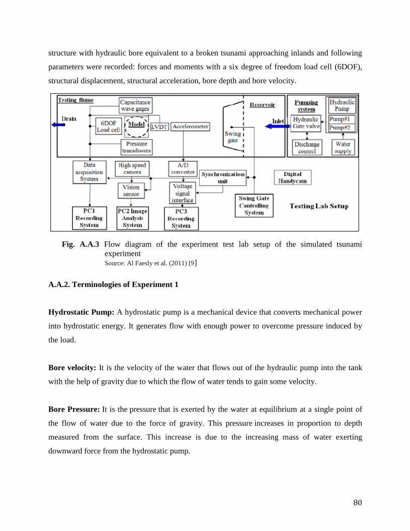
80
structure with hydraulic bore equivalent to a broken tsunami approaching inlands and following
parameters were recorded: forces and moments with a six degree of freedom load cell (6DOF),
structural displacement, structural acceleration, bore depth and bore velocity.
A.A.2. Terminologies of Experiment 1
Hydrostatic Pump: A hydrostatic pump is a mechanical device that converts mechanical power
into hydrostatic energy. It generates flow with enough power to overcome pressure induced by
the load.
Bore velocity: It is the velocity of the water that flows out of the hydraulic pump into the tank
with the help of gravity due to which the flow of water tends to gain some velocity.
Bore Pressure: It is the pressure that is exerted by the water at equilibrium at a single point of
the flow of water due to the force of gravity. This pressure increases in proportion to depth
measured from the surface. This increase is due to the increasing mass of water exerting
downward force from the hydrostatic pump.
Fig. A.A.3 Flow diagram of the experiment test lab setup of the simulated tsunami
experiment
Source: Al Faesly et al. (2011) [9]

81
Bore Force: It is the force exerted by the water into the walls of the bore of the hydrostatic
pump keeping the water at rest.
Hydrodynamic Force: the motion of water flow and the force acting on solid body (the
aluminum frame model in the experiment) immersed in fluids and in motion relative to them.
A.A.3. Principle of the experiment
Bore Velocity: There were many formulations that were proposed by many organizations and
researchers. FEMA 55 presented a formula U max= 2(gh)1/2
whereas CCH 2000 assumed that
U=h (ft/s), researchers such as Brian proposed U= (1.67h)0.7
, Murty proposed U=1.83(gh)0.5
. But
the formula that is most widely used is U= (2gR)0.5
where U is velocity, g is gravitational
constant and R is the ground elevation.
Bore Velocity Tests: In the first stage of the experimental work, tests were conducted using
hydraulic bores generated by the sudden release of impounding water depths of 400mm, 550mm,
700mm, 850mm, and 1150 mm in the absence of the structure model. The data recorded was
used to obtain the bore profile as well as the bore velocity. The data was then used to calculate
bore velocity. To capture slow-motion videos of the advancing bore, a high speed camera was
installed in the model. By tracking the bore front frame-by-frame and based on the geometry of
the grid lines, the authors were able to derive the bore front velocity at different successive
sections along the flume longitudinal axis. As seen in Figure 2, three pairs of wave gauges were
installed in the flume for this particular test series.
Spacing between successive pairs of gages was 1 meter. Bore velocity was also
calculated using the time interval required for the bore to travel between the wave gauges while
reaching a specified water level (30 mm, 40 mm, 50 mm, and 60 mm). To determine the time for
a specific water level at a given location of a wave gauge, a cross correlation function was used
for the data recorded by each pair of wave gauges position on the same transversal row.
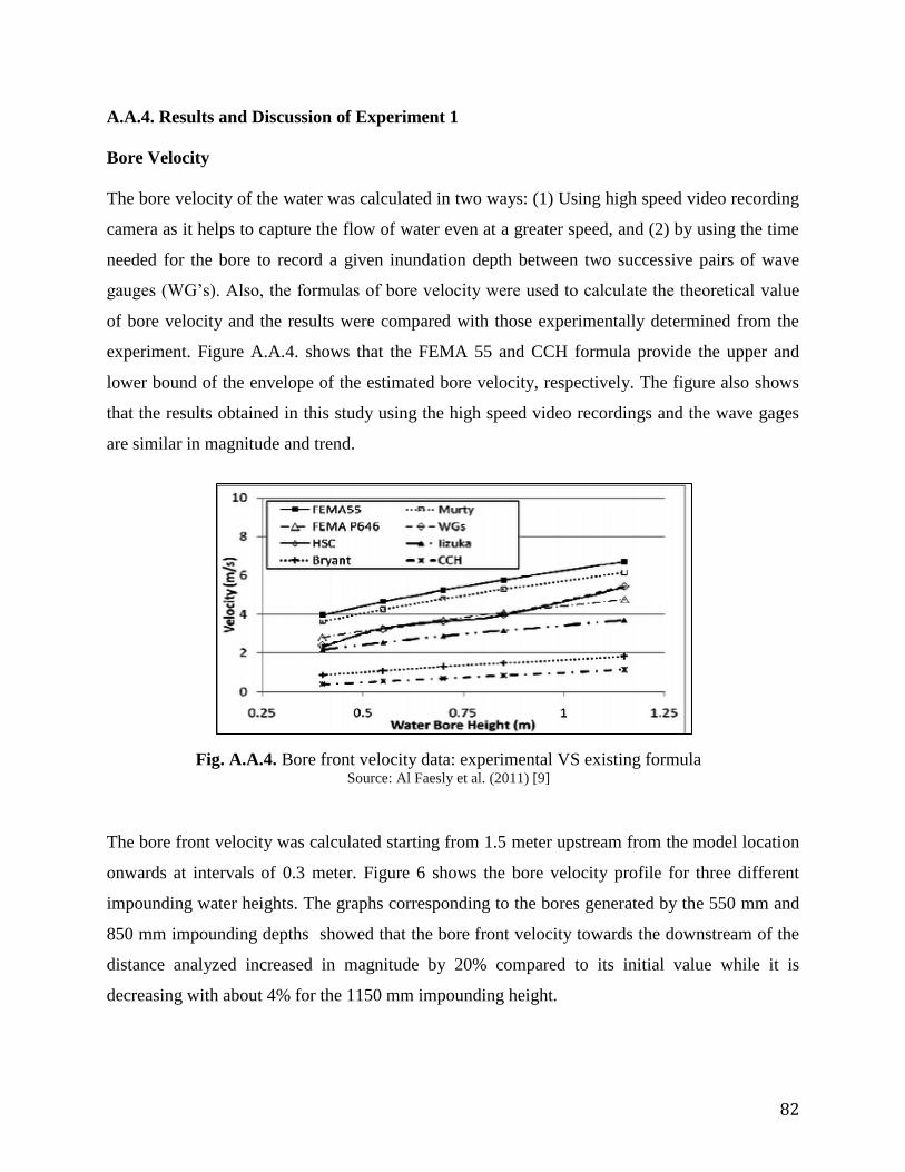
82
A.A.4. Results and Discussion of Experiment 1
Bore Velocity
The bore velocity of the water was calculated in two ways: (1) Using high speed video recording
camera as it helps to capture the flow of water even at a greater speed, and (2) by using the time
needed for the bore to record a given inundation depth between two successive pairs of wave
gauges (WG’s). Also, the formulas of bore velocity were used to calculate the theoretical value
of bore velocity and the results were compared with those experimentally determined from the
experiment. Figure A.A.4. shows that the FEMA 55 and CCH formula provide the upper and
lower bound of the envelope of the estimated bore velocity, respectively. The figure also shows
that the results obtained in this study using the high speed video recordings and the wave gages
are similar in magnitude and trend.
The bore front velocity was calculated starting from 1.5 meter upstream from the model location
onwards at intervals of 0.3 meter. Figure 6 shows the bore velocity profile for three different
impounding water heights. The graphs corresponding to the bores generated by the 550 mm and
850 mm impounding depths showed that the bore front velocity towards the downstream of the
distance analyzed increased in magnitude by 20% compared to its initial value while it is
decreasing with about 4% for the 1150 mm impounding height.
Fig. A.A.4. Bore front velocity data: experimental VS existing formula Source: Al Faesly et al. (2011) [9]

83
The experiment was conducted in two conditions: wet bed and dry bed conditions. For the wet
bed condition the impact force was smaller than the run up force and for dry bed condition the
impact force had the biggest magnitude in comparison to run up and quasi-steady
hydrodynamics. With the determination of the bore velocity, bore force and the bore pressure we
can determine the velocity, force and the pressure exerted by a series of waves (Tsunami).

84
APPENDIX - PART B: EXPERIMENT-2
Another analysis was made by three researchers namely Tiecheng Wang, Tao Meng, Hailong
Zhao in Japan where structural response to effects of Tsunami was analysed [32]. Tsunami is
mainly triggered by strong sea quake, underwater volcano eruption, as well as large-scale
underwater or coastal landslide. However, among the causes leading to tsunami, the sea quake is
the most primary reason especially the dip-slip type quake that staggers up and down along the
fault surface. The last decade has been witness to a number of major tsunamis that have resulted
in catastrophic human and economic losses to coastal communities. (Indian Ocean 2004, Chile
2010 , and Japan 2011 ). As for this, to analyse the magnitude and distribution of tsunami forces
on the structure and to study the response of structure under the impact of tsunami forces has an
important meaning in improving the performance of structure, resisting tsunami disaster, as well
as reducing casualties and economic losses.
It is an important theoretical research method to numerically simulate and analyse the interaction
between tsunami waves and structures, so as to figure out the response of structures under the
impact of tsunami waves. This method is effective in complementing the defects of some
experimental researches. In this paper, based on the computational fluid dynamics software of
FLOW-3D, the method of Volume of Fluid (VOF) is utilized to capture free interface, and the
ideal solitary wave model is applied to simulate tsunami waves. Through simulating and
analysing the three-dimensional numerical model of reinforced concrete frame structure under
the impact of tsunami waves, the magnitude and distribution of tsunami forces can be
ascertained.
A.B.1. Numerical simulation of tsunami forces
Tsunami waves are of long period gravity wave, and gravity is a restoring force. Gravity
has the tendency to restore the disturbed sea water back to the undisturbed state. When the
gravity waves are propagating in the seawater, gravity can transfer wave energy from the
excessive regions to the insufficient regions. Moreover, as sea water is incompressible, tsunami
waves are also considered as an incompressible viscous fluid motion. FLOW-3D takes the

85
continuity equation and the Navier-stokes equation for incompressible viscous fluid motion as
the control equation for fluid motion. The equation expressions are listed as follows:
Continuity equation:
Momentum Equation:
A.B.2. Model of tsunami impact on the structure
When waves travel into near shore shallow water areas, the shape and motion of tsunami
waves closing to breaking is quite similar to the solitary wave. By researching the propagation of
tsunami waves, Hammack and Segur pointed out that under the circumstance with positive net
volume variation, some solitary waves with stable shapes could be generated. As for this, the
ideal solitary wave is employed to simulate tsunami wave in this paper. The propagation velocity
of ideal solitary wave and tsunami wave in the ocean can be calculated by
C= [g (H+d)]0.5
Where g refers to the gravitational acceleration, H represents the height of solitary wave, and d
indicates the depth of still water, in which the solitary wave travels.
C= (gh)0.5
Where h refers to the depth of sea water, in which the tsunami wave spreads. Similar to the ideal
solitary wave, tsunami wave also has very long wave length and relatively small wave height.
0
z
w
y
v
x
u
x
p
z
uw
y
uv
x
uu
t
u
1
y
p
z
vw
y
vv
x
vu
t
v
1
gz
p
z
ww
y
wv
x
wu
t
w
1

86
The propagation velocity may be calculated from the above two equations, which are determined
by the depth of water.
The model constructed in this experiment was an incompressible and viscous flow model,
and Newtonian viscosity with renormalized group (RNG) k-ε turbulence model was adopted. The
boundary conditions and geometric dimension of the model are shown in Fig. A.B.2.. The left
side is the entrance border (In Flow) of the incident wave. It is set as H is equal to 2 m and the
Figure A.B.1: Plane and elevation layout of the structure (in mm) Source: Wang et al (2015) [32]
Figure A.B.2. Model Boundary conditions and geometric
dimension Source: Wang et al (2015) [32]

87
incident wave height d is equal to 3 m, therefore, the velocity of the incident wave is 7 m/s. The
right side of the figure shows the exit border (Out Flow) of tsunami wave, which allows water to
flow out freely. The up and down side of the figure were set as symmetry boundary condition. At
the symmetry boundary, the flow flux of the fluid was zero and the tangential stress was 0, i.e.,
the fluids at two sides of the symmetry boundary were continuous. In order to better simulate the
motion of tsunami wave before impacting the structure, the influence of seaside slope on
propagation of the tsunami wave is comprehensively considered. As for this, a 10 % slope is set
at the front side of the structure to simulate the coast.
In the simulation process, in order to compare the influence of tsunami wave on the
structure separately with and without walls conditions at the upstream face at the bottom of the
structure, the paper conducts simulation in two different cases. Case 1: The upstream face on the
bottom floor of the building is constructed with walls, and the area ratio between holes and walls
is 1:4, which is shown in Fig. 1(b). In the impacting process, the walls are not damaged, while
the connection with the main structure is intact, as is shown in Fig. 3(a). Case 2: The upstream
face on the bottom floor of the building has no walls. Floors from 2 to 5 are constructed with
walls, and also the ratio between holes and walls is 1:4. In the impacting process, only columns
on the bottom floor are bearing load from tsunami waves, as is shown in Fig. 3(b).
Fig. A.B.3. (b) Case 2 Source: Shuto (1993) [49]
Fig. A.B.3. (a) Case 1 Source: Wang et al (2015)
[32]

88
A.B.3. Tsunami wave forces simulation results
Based on simulation, Fig. 4 shows the time-history curves of tsunami wave horizontal
thrust on the frame structure in Case 1 and Case 2. During the time period from 3.0 sec to 6.5 sec
in Case 1, the horizontal thrust of tsunami wave impacting on the structure presents a tendency
of linear increment. After that, blocked by the upstream walls, local tsunami waves are reflected
so that tsunami load on the structure is reduced in a short period. Then, as the reflected wave
gradually decreases there is gradual increase in the load on the structure which reaches its
maximum value of 7909.6 KN at 8.3 sec. At the moment the tsunami wave reaches the largest
run-up height and is strongly instable. After the tsunami wave reaches the largest run-up height,
the load on the structure decreases sharply, this finally stabilizes at 12 sec. At the moment, the
structure is in a stable state of being impacted by tsunami waves.
In Case 2 as the bottom of the structure is not constructed with upstream walls, there are
only columns on the bottom floor to bear the impact from tsunami waves, so that the impacting
area of the structure with tsunami waves is quite small. Before 9 seconds, all loads generated
from tsunami waves are impacting on columns of the bottom floor, and tsunami load on the
structure increases gradually. Afterwards the run-up height of tsunami waves increases
continuously and the upstream walls of the second floor start to come contact with the tsunami
waves. As for this, tsunami load on the structure takes on a rapid increment tendency which is
stabilized after 12 seconds and reaches the maximum value of 2129.2 KN at 13.8 seconds. When
impacting with the structure in Case 2, tsunami waves encounter quite limited resistance, with
small wave reflection. Thus, when compared with the situation in Case 1, the variation in
amplitude of tsunami wave impacting on the structure in Case 2 are much gentler.

89
The maximum tsunami wave force impacting the structure in Case 2 is much less than that in
Case 1. Moreover, the occurrence time of maximum tsunami wave force on the structure is later
than that in Case 1. When no in filled wall is constructed on the upstream face of the bottom
floor of the structure, there would be only columns on the bottom floor bearing the impact from
tsunami waves, so that the resistance as water passes through the structure is smaller. Therefore,
the structure in Case 2 is more effective in resisting tsunami waves.
Fig.A.B.4. Comparison of Tsunami Load on Case 1 vs. Case 2 Source: Wang et al (2015 [32]

90
APPENDIX – PART: C
A.C.1. General Design factors to construct buildings in coastal areas as proposed by
National Disaster Management Authority
Table A.C.1. General Design factors to construct buildings in coastal areas as proposed
by National Disaster Management Authority. Source: NIDM [38]
A.C.2. RC design criteria for all coastal areas
Concrete used to build structures that are exposed to coastal Environments should have
following characteristics:
(i) Plain: Min M20, Cement: min 250 kg/m3
(ii) RC: Min M30, Cement: min 320 kg/m3 Max aggregate: 20 mm Min cover for slabs: 20
mm Min cover for beam: 30 mm 3 Min cover for column1: 40 mm Reinforcement:
TMT – HCR Fe 415 for up to 2 stories. Use Fe 500 for frames in taller buildings
(iii) HCB: To be casted using M 20 concrete with fly ash. Reinforcement TMT – HCR Fe
415 bars, concrete filling M 20 grade
Housing Important
Building
Cyclone Shelter/Very
Important Installation
Wind Speed IS:875(3)
1.15 X
IS:875(3)
1.3 X IS:875(3)
Factor of
pressure
K1
K2
K3
1.0
1.05
1.00
1.08
1.05
1.00
1.08
1.05
1.00
Seismic coeff.
IS:1893 (1)
I=1.0, R as per
code
I=1.5, R as
per code
I=1.8, R as per code
Storm Surge As per Vulnerability Atlas of India, 1997 riding over maximum
astronomical tide level
Fire safety 1.5 hr rating 2 hr rating ≥ 2 hr rating
Flood safety Plinth height at
recorded high
flood level or
corresponding to
10 yr flood
50 yr flood
100 yr flood
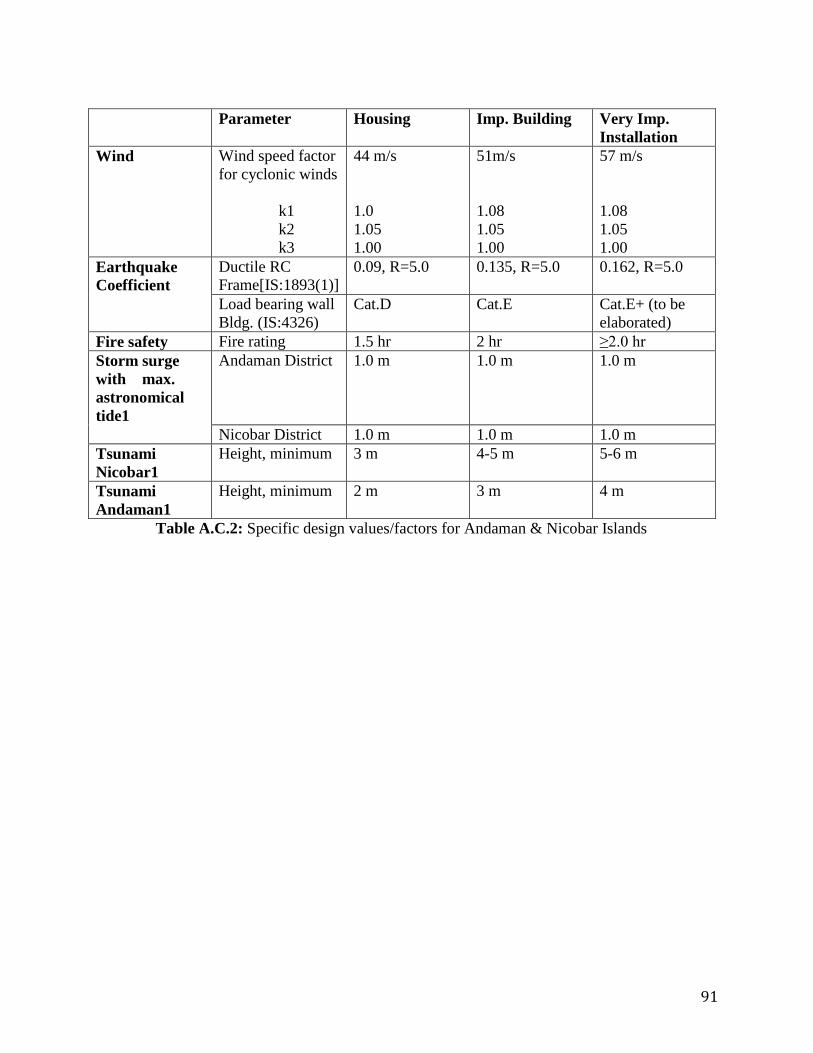
91
Table A.C.2: Specific design values/factors for Andaman & Nicobar Islands
Parameter Housing Imp. Building Very Imp.
Installation
Wind Wind speed factor
for cyclonic winds
k1
k2
k3
44 m/s
1.0
1.05
1.00
51m/s
1.08
1.05
1.00
57 m/s
1.08
1.05
1.00
Earthquake
Coefficient
Ductile RC
Frame[IS:1893(1)]
0.09, R=5.0 0.135, R=5.0 0.162, R=5.0
Load bearing wall
Bldg. (IS:4326)
Cat.D Cat.E Cat.E+ (to be
elaborated)
Fire safety Fire rating 1.5 hr 2 hr ≥2.0 hr
Storm surge
with max.
astronomical
tide1
Andaman District 1.0 m 1.0 m 1.0 m
Nicobar District 1.0 m 1.0 m 1.0 m
Tsunami
Nicobar1
Height, minimum 3 m 4-5 m 5-6 m
Tsunami
Andaman1
Height, minimum 2 m 3 m 4 m