resistive magnetohydrodynamics liu jian 2006.10.31 email: [email protected] mobile phone: 138 1000...
TRANSCRIPT

Resistive Magnetohydrodynamics
Liu Jian
2006.10.31
Email: [email protected] Mobile Phone: 138 1000 1317

Outline of This Chapter
Introduction Magnetic relaxation and reconnection Resistive instabilities Magnetic field generation The solar wind MHD shocks

From Ideal MHD to Resistive MHD
20
2
μ
B)1)(η(γuγP
Dt
DP
B)(uμ
Bη
t
B
0
2
The dissipative terms are of higher differential order than the non-dissipative terms ,so even a very small amount of dissipation can lead to solutions which are significantly different from those of ideal MHD.

Lundquist Number
definition: is the characteristic times for resistive
diffusion and convection. is the Alfvén transit time. When S is large enough ,we can take on the ideal MH
D approximation. sunspot data (see table5.1 on Page 141) :
Why?
// 0 LvS AAR /2
0LR
AA vL /
914 10;10 SR

Explanation of The Problem
There must be some much faster mechanism. The large S may not caused by the entirely negligible
resistivity ,but compared with L the length scale of the region considered is very small.
In this case ,ideal MHD is valid for most of the plasma ,but in the narrow boundary layers we must apply resistive MHD.
Within such regions, topological changes take place on a time scale intermediate between diffusion time and Alfvén time, which enable the system to arrive at a lower energy state.

Magnetic Reconnection
neutral sheet :the plane in which B=0.
field is slowly varying with y, decreasing in magnitude, reversing sign, and then increasing again.
field line define the x-axis current j is parallel to the z-axis Lorentz force j×B acts downwards f
or y>0, and upwards for y<0.

Magnetic Reconnection
In ideal MHD, either these forces are opposed by a plasma pressure gradient maintaining equilibrium or plasma and field lines will move together towards the y=0 plane until these forces are balanced.
However, if we introduce finite resistivity, no matter how small, the field is no longer frozen in to the plasma. The field lines will move across the plasma and this allows to breaking of the field lines with reconnection to lines of opposite polarity.
BjP

reconnection

Magnetic Island
The addition of resistivity allows magnetic field lines to break and reconnect so that they are no longer frozen into the fluid as described in Chapter4.
This has a profound effect on the MHD model. With resistivity, the magnetic field tends to break up into a
number of thin filaments called magnetic islands which thread their way through the plasma.
Since heat flows rapidly along field lines, one of the direct effects of this island structure is to enhance transport across the plasma.

Magnetic Island
reconnection may happen at various points along the neutral lines, give rise to so-called magnetic islands.
The null-points of the magnetic field define O-points at the axes of the magnetic islands, and X-points at the intersections of the separatrix.

The topological change takes place because the magnetic energy associated with the magnetic islands is less than that in original MHD equilibrium configuration.
Imagine the field lines as stretched strings: the tension in them has been reduced because breaking and reconnecting allows them to contract around the island axes.

Magnetic Helicity :K
definition:
It provides a measure of the complexity of the magnetic field topology.(P103, why? how?)
see derivation details in《等离子体理论基础》,胡希伟, Page 14
V
dBAK

21
2
21
VVV
dBAdBAdBAK
211S111
1
V
11
V
11
V
1
V
ΦΦdSAΦdlAdσ B
)(dlA)(dσ)dlB)(A(dσdlBdσABdτA
1
1111
B
For the right picture: 0K

Taylor’s Hypothesis
Woltjer showed that the helicity K of ideal plasma is conserved for every volume enclosed by a flux surface.
Taylor’s hypothesis states that only the helicity associated with the total volume of the plasma is conserved.
It means that the final state of the plasma is largely independent of its initial conditions.

Driven Reconnection
spontaneous reconnection and driven reconnection. Sometimes (i.e. in plasmas collision—in solar flares an
d when the solor wind strikes the Earth’s magnetosphere), driven reconnection may occur.
Using Lundquist number as an index of the spontaneous reconnection rate: 11 SM sp

dvuL A
du 02/
2/1/ Svu A 2/1/ SLd
2/1/ SvuM Adr
According to mass conservation
Under steady state conditions, the rate at which magnetic flux is convected towards the current sheet by the plasma flow is balanced by the rate of ohmic dissipation,so that
From these two equations, we can get
Thus

Theory Development
Sweet-Parker model: developed by Parker(1963)– The Sweet-Parker reconnection rate is much too
slow to characterize some faster mechanism. Petschek(1964) reasoned that the magnetic fields
would meet at a relatively narrow apex, rather than across the entire region envisaged in the Sweet-Parker model, and found a maximum reconnection rate:
1)(ln SM dr

Driven Reconnection

Resistive Instabilities
It might be expected that the addition of resistivity or viscosity or heat conductivity to the ideal equations would only reduce the growth rate of instabilities because resisitivity would dissipate away electrical currents, viscosity would damp out any sheared velocities, and heat conductivity would diminish local thermal gradients which could provide a source of free energy.
However, it is important to realize that the addition of dissipation can produce new instabilities by removing constraints from the ideal equations and, thereby, making states of lower energy accessible to the plasma.

Resistive Instabilities
The ability of a plasma, through magnetic reconnection, to reach lower energy states means that the ideal MHD stability needs re-examination.
Allowing for variable resistivity, we can get:
Thus we can introduce the driving term for one of the resistive instabilities.
00
2 B)(η-B)(u
μ
Bη
t
B

Resistive Instabilities
The relaxation of constraints can also make existing instabilities grow faster.
The growth rate of resistive instabilities is determined by how fast the magnetic field lines can be broken, viewed as a kind of throttling process, balanced against the driving forces and inertial effects.
It is an important feature of these instabilities that the field lines need to be broken only in a thin boundary layer within the plasma.

Resistive Instabilities
Since the dissipation process is governed by a diffusion equation, the time scale for the throttling process is determined by the width of the boundary layer squared divided by the diffusion coefficient.
If the boundary layer thickness were comparable to the radius of the plasma, the result would be resistive diffusion which proceeds on a very slow time scale compared to most MHD instabilities.
If the boundary layer were too thin, inertial effects would limit the growth rate of the instability.

Resistive Instabilities
When all the effects are balanced, it turns out that the resistive instabilities grow on a time scale much slower than the Alfvén transit time scale and much faster than the typical diffusion time scale.
There are three kinds of instabilities whose growth times much smaller than but much greater than
tearing mode (spontaneous instability) gravitational interchange mode (driven instability) rippling mode (driven instability)
see table 5.2 on P156
R A

Tearing Instability

m=1 Resistive Kink Instability

Rayleigh-Taylor Instability
Resistive g mode and rippling mode has similar mechanism with Rayleigh-Taylor instability.

Tokamak Instability
The tearing mode also makes its appearance in cylindrical and toroidal plasmas, in which the resonant surfaces occur at the mode rational surfaces. (P158 Fig.5.9)
Tearing mode instabilities are believed to be the source of Mirnov oscillations, which are magnetic fluctuations occurring during the current rise in tokamaks. (P159 Fig.5.10)

Sawtooth Oscillations
Another instability, observed in the soft X-ray emission from tokamaks.
For example, the m=1 kink mode occurring in the centre of the plasma.
The outer region of the plasma show the inverse pattern, indicating that temperature changes in the outer plasma compensate those occurring in the central plasma due to the instability.


Development of Sawtooth
Slow build-up process:– Inner region of plasma is hotter.– conductivity σ=1/η increases with temperature– current I increases– ohmic heating increases, which makes the inner region hotter h
otter– this leads to an unstable concentrating of current in the centre
of plasma– the poloidal magnetic field increases– safety factor q falls
RI
Ba
aRB
aBq
0
22
)(
rIB 2/0

Development of Sawtooth
Sudden fall process– q<1 allowing the q=1 surface near the axis– m=1 instability develop at the q=1 suface
see Page161 Fig.5.12
– reconnection accurs– q>1 islands displace the hot island– hot island slowly decays and disappears by therm
al conduction to the cooler plasma the procedure is repeated

Disruptive Instability
It can lead to the collapse of the plasma current. Principal characteristics: rapid broadening of the current
profile with consequent decrease in the poloidal field, followed by a loss of thermal energy from the plasma to a degree that quenches the discharge.
Magnetic surfaces are destroyed by tearing modes with different helicities at different resonant surfaces.
It is the least well understood of the tokamak instabilities.

Disruptive Instability
Observation indicate that m=2 tearing mode is crucially involved.
m=2 mode triggers the precursor phase (Page162) non-linear interaction with m=1 or m=3 modes involved the growth in amplitude over a period of about 10ms
triggers the fast phase in which the central temperature collapses and the radial current profile flattens in a time of the order of 1ms.


Magnetic Field Generation
Magnetic field of the Universe ranging in magnitude from background level to neutron stars. (vast)
Where do magnetic fields come from??? trapped in the original formation of galaxy, trapped
from the interstellar matter. How the observed magnetic fields of stars and
planets are sustained?---------this is a long-standing and challenging problem in MHD.

Magnetic Field Generation
There are two possible mechanisms by which magnetic fields may be regenerated. (like dynamo or battery)
One requires some initial field on which the fluid motion can act.
The other one doesn’t have the requirement– suggested by Biermann (1950)– cannot generate sufficient strong fields– if all other fails, it guarantees a seed field for stars
and galaxies

The Kinematic Dynamo
use the kinetic energy in flow field kinematic dynamo problem: try to device a flow field
which will maintain a magnetic field against resistive decay. It involves too many equations to be analyzed.
anti-dynamo theorem: in 1934,Cowling showed that a steady, axisymmetric magnetic field cannot be maintained.
The proof of Cowling’s theorem can be extended to include an azimuthal component of the magnetic field

The Kinematic Dynamo
existence theorems: Herzenberg(1958) and Backus (1958) proved existence theorems for possible dynamo mechanisms for steady and oscillating fields respectively.
This leads to rapid development of other dynamo models.
The kinematic problem is now broadly understood except for its mathematical complexity.

Stretch-twist-fold Cycle

Stretch-twist-fold cycle
Suggested originally by Zel’dovich in 1972 Stretch-twist-fold cycle (see Fig 5.15 on P165) Can obtain a field of twice the original strength through t
he fixed loop C. It illustrates how the field strength may be increased fro
m an arbitrarily low level. It’s necessary to explain what kind of a flow might realis
tically produce this effect. The answer lies in the combination of α-effects and Ω-e
ffects.

Ω-effect
Ω denotes the rate of angular rotation of a conducting sphere.
Ω varies with distance from the axis of rotation.
The differential rotation rate arises when convection currents are subjected to a combination of buoyancy and Coriolis forces.By conservation of angular momentum, descending fluid elements increase their rate of rotation.

A field line passing through the rotating sphere is wound around the axis of rotation rather than simply being carried around, as would be the case if the rotation rate was uniform.
Thus, a purely poloidal field can create a toroidal field component.

α-effect
The α-effect creates a poloidal component from a purely toroidal field. The book gives an example to explain that a flow can deform a straight magnetic field line into a helix. In ideal MHD, j paralel to B produces a helical field.While
the electromotive force j×B gives rise to a current component perpendicular to B.
Only when the effect of finite resistivity shifts the phase of the magnetic field perturbation b relative to j, that a space average < j×B > leads to a current component parallel to B.

Combined αΩ-mechanism
Thus the combined αΩ-mechanism comprises a regenerative cycle.
It is now widely accepted that it is by this cycle that the magnetic fields of the Earth and Sun are maintained.
At present, the physical existence of fast dynamos has not been conclusively established.
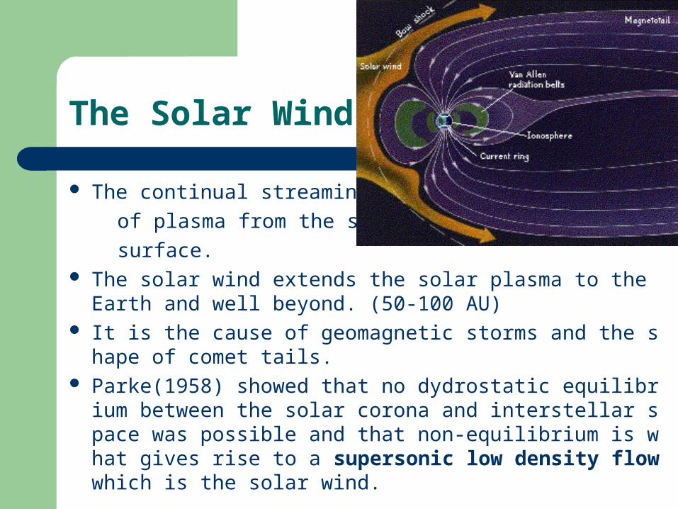
The Solar Wind
The continual streaming
of plasma from the sun’s
surface. The solar wind extends the solar plasma to the Earth and
well beyond. (50-100 AU) It is the cause of geomagnetic storms and the shape of c
omet tails. Parke(1958) showed that no dydrostatic equilibrium betw
een the solar corona and interstellar space was possible and that non-equilibrium is what gives rise to a supersonic low density flow which is the solar wind.

The Solar Wind
The solar wind is composed largely of protons and is permeated by a magnetic field.
Solar wind characteristics (see table 5.3 on page 170) Because of the Sun’s rotation, the magnetic field is twiste
d into a spiral. It exhibits a complex structure attributable in part to the admixture of open and closed magnetic structures at the Sun’s surface.
In a general sense open magnetic structures are favourable to the generation of the solar wind while closed structures oppose it.


Reconnection in Solar Wind

MHD Shocks
Supersonic flow gives rise to the generation of shock waves.

the sound speed is greatest at the peak of a finite amplitude wave, so the wave-front steepens.
Since the wave-front deepens, the dissipative effects become stronger. the dissipative effects are proportional to gradients in the fluid variables.
When the convective steepening is counter-balanced by the dissipative flattening, a steady profile is achieved.
The smaller the coefficients of dissipation, the more nearly the shock wave approaches a vertical discontinuity.
1 sc

We usually regards a shock as a transition region between to uniform states. see (a)
In practice, the situation (b) is more likely. The shocked fluid is not in a uniform state but is subject to a relief or expansion wave.
The valid of assumption depends on the time of relaxation.

Hydromagnetic Shocks
Hydrodynamics shock has been well-understood.– see “Waves in fluids” Lighthill, M.J., Sir
Hydromagnetic case is more complicated. Conducting fluids in a magnetic can support two further
modes of wave propagation.– In non-conducting fluid, transverse movements have no effect.
3 degrees of freedom-3 modes of wave propagation-3 propagation speeds: fast intermediate and slow.
– Intermediate waves are purely transverse, do not form shock waves
– The fast and slow modes contain both transverse and longitudinal components, and give rise to shocks.

Hydromagnetic Shocks
More fundamental differences between shocks in neutral fluids and in plasmas arise in shock structure.
Striking is the existence of shocks with thicknesses much less than the collisional mean free path. These collisionless shocks cannot be MHD shocks.
For collision-dominated shocks two factors greatly facilitate discussion of the effects of a shock wave on a fluid:
– 1.The shock transition region may be approximated by a discontinuity in fluid properties.
– 2.The macroscopic conservation equations and the Maxwell equations may be integrated across the shock to give a set of equations which are independent of shock structure and relate fluid properties on either side of the shock.

Shock Equations
For simplicity, we just discuss plane shocks moving in a direction normal to the plane of the shock (x direction).
All variables are functions of x only inside the shock and are constant outside the shock.
It’s convenient to use a frame of reference in which the shock in at rest, depicted in the figure above.
The MHD equations do not apply in the shock region since dissipative process take place there, but they do apply on either side of the shock.
We can write down Maxwell equation for j; Ohm’s law; the equations of conservation of mass, momentum, and energy. Then we shall integrate them across the shock and evaluate them in the upstream and downstream plasma.
Shock

Jump Conditions
0]/)(/)(2/[
;0]/[
;0]/[
;0]2/)([
;0][
0][;0][;0][
2100
222
210
210
210
222
21
21
21
21
zzyyxzyxxxx
zxzx
yxyx
zyx
x
xzzxxyyxx
uBuBBBBuuuPuIu
BBuu
BBuu
BBPu
u
BuBuBuBuB
We can obtain these equations called jump conditions:
I=P/(γ-1)ρJump conditions can be written in general vector form (5.63)-(5.66) on P184

The first three equations represent the conservation of mass, momentum, and energy, respectively for the flow of the plasma through the shock.
The last pair gives the jump conditions for the magnetic field expressing the continuity of the normal component of B and the tangential component of E=-u×B.
When B=0, these equations reduce to the corresponding hydrodynamic equations known as the Rankine-Hugoniot equations.

Hugoniot Relation
0]/1[}]{[4
1]/1)[(
2
1][ 2
122
10
2121
21
BPPI
0]/1)[(2
1][ 2
12121 PPI
From the equations above we can get:
The hydrodynamic equivalent of this equation is:
Hydromagnetic Hugoniot reduces to hydrodynamic one not only when the magnetic field is zero but also wen B1 and B2 are both parallel to the direction of shock propagation.

We can prove the compressive nature of shocks. (see Page184-186) i.e. P2>P1
The angle θ between B1 and n is used to classify shocks as parallel (θ=0), perpendicular (θ=π/2), and oblique (0<θ< π/2).
We also can set the unshocked fluid flow u1 is normal to the stationary shock front. This means we choose a frame moving with the shock speed in the x direction and the tangential flow speed u1y of the unshocked fluid in the y direction.

Parallel Shocks
Here, both u1 and B1 are parallel to n. One possibility is that B2=B1, so u2 is also parallel to
n It may happen that some of the flow energy is
converted into magnetic energy , so that
Since the normal component of B is conserved this means that the passage of the shock creates a tangential component and it is said to be a switch-on shock
12 BB

Oblique Shocks

Welcome to our website
– Get useful information.– Discuss courses and academic problems– Give us your invaluable advice– ……
Please come to
http://www.phy.pku.edu.cn/~fusion/