resistor selection - power and microwave tubes - rell ... · pdf fileresistor selection...
TRANSCRIPT

1-866-9-OHMITE • Int’l 1-847-258-0300 • Fax 1-847-574-7522 • www.ohmite.com • [email protected] 195
Resistor SelectionApplication NotesR e s i s t o R F A c t s A N d F A c t o R s
Why Watts Must Be Accurately KnownStated non-technically, any change in current or voltage produces a much larger change in the wattage (heat to be dissipated by the resistor). Therefore, the effect of apparently small increases in current or voltage must be investi-gated because the increase in wattage may be large enough to be significant. Mathematically, the wattage varies as the square of the current, or voltage, as stated in the formulas (b). For example, an increase of 20% in current or voltage will increase the wattage 44%. Figure 1 below graphically illustrates the square law relation. Hence, the actual current must be used in figuring the wattage and the increase in wattage due to appar-ently small changes, then determined in order to select the proper size resistor. Allowance should be made for maximum possible line voltage.
A resistor is a device connected into an electrical circuit to introduce a specified resistance. The resistance is measured in ohms. As stated by Ohm’s Law, the current through the resistor will be directly proportional to the voltage across it and inverse-ly proportional to the resistance.
The passage of current through the resistance produces heat. The heat produces a rise in temperature of the resis-tor above the ambient temperature. The physical ability of the
resistor to withstand, without deterioration, the temperature attained, limits the operating temperature which can be permit-ted. Resistors are rated to dissipate a given wattage without exceeding a specified standard “hot spot” temperature and the physical size is made large enough to accomplish this.
Deviations from the standard conditions (“Free Air Watt Rating”) affect the temperature rise and therefore affect the wattage at which the resistor may be used in a specific applica-tion.
s e l e c t i o N R e q u i R e s 3 s t e p s
Simple short-cut graphs and charts in this catalog permit rapid determination of electrical parameters. Calculation of each parameter is also explained. To select a resistor for a specific application, the following steps are recommended:
1 . (a) Determine the Resistance. (b) Determine the Watts to be dissipated by the Resistor.
2 . Determine the proper “Watt Size” (physical size) as controlled by watts, volts, permissible temperatures, mounting conditions and circuit conditions.
3 . Choose the most suitable kind of unit, including type, terminals and mounting.
s t e p 1 d e t e R m i N e R e s i s t A N c e A N d w A t t s
Ohm’s Law
(a) R = V or I = V or V = IR I ROhm’s Law, shown in formula form above, enables determination of the resistance when the required voltage and current are known. When the current and voltage are unknown, or the best values not decided on, at least two of the three terms in Ohm’s Law must be measured in a trial circuit.
(b) P = I2R or P = VI or P = V2
RPower in watts, can be determined from the formulas above, which stem from Ohm’s Law. R is measured in ohms, V in volts,I in amperes and P in watts.
Fig. 1: Rapid increase of wattage with current or voltage.
100
400
Per
cen
t R
ated
Wat
ts
Percent Currentor Voltage
300
200
100
02000
s t e p 2 p o w e R R A t i N g o R p h y s i c A l s i z e o F R e s i s t o R
A resistor operated at a constant wattage will attain a steady tem-perature which is determined largely by the ratio between the size (surface area) and the wattage dissipated, The temperature stabilizes when the sum of the heat loss rates (by radiation, convection and conduction) equals the heat input rate (proportional to wattage). The greater the resistor area per watt to be dissipated, the greater the heat loss rate and therefore the lower the temperature rise. The rela-tion between the losses varies for different resistors.Free Air Watt RatingThe wattage rating of resistors, as established under specified stan-dard conditions, is defined as the “Free Air Rating” (“Full Rating” or “Maximum Power Rating”). Several standard methods of rating are in use based on different service conditions. The method of both
the “National Electrical Manufacturers Association” (NEMA) and the “Underwriters’ Laboratories, Inc.” (UL) can be described as follows:
The relation of the “Free Air Watt Rating” of tubular type, vitre-ous enameled resistors to the physical size, is to be set at such a figure that when operated at their rated watts, the temperature rise of the hottest spot shall not exceed 300°C (540°F) as measured by a thermocouple when the temperature of the surrounding air does not exceed 40°C (104°F). The temperature is to be measured at the hottest point of a two-terminal resistor suspended in free still air space with at least one foot of clearance to the nearest object, and with unrestricted circulation of air.
A slightly different definition of temperature limit used as a basis for wattage rating, and which results in a slightly higher attained temperature, was originally established in military specification MIL-

1-866-9-OHMITE • Int’l 1-847-258-0300 • Fax 1-847-574-7522 • www.ohmite.com • [email protected]
Resistor SelectionApplication NotesR-26 for wirewound resistors.
Characteristic V resistors are required to dissipate rated wattage in an ambient of 25°C without exceeding a maximum operating temper-ature of 350°C at the hottest spot. This corresponds to a temperature rise of 325°C in a 25°C ambient. Although MIL-R-26 permits a 25°C greater temperature rise than NEMA or UL, the reference ambient for the latter two is 15°C higher. Consequently, the difference in attained temperature between the two systems is only 10°C. The curves in Fig. 2 show the relation between temperature rise and wattage for various specifications. Note the differences in the permissible rise for
each specification.The absolute temperature rise for a specific resistor is roughly
related to the area of its radiating surface. It is also dependent upon a number of other factors, however, such as thermal conductivity of the core and coating materials, emissivity factor of the outer surfaces, ratio of length to diameter, heat-sink effect of mountings, and other minor factors.
The maximum permissible operating temperature for a given resistor is basically determined by the temperature limitations imposed by the materials used in its construction. Generally speak-ing, these limits cannot be sharply defined in terms of temperature alone. Other factors such as resistance stability versus time, dete-rioration rates of insulation and moisture-resistance characteristics, type and size of resistance wire, all enter into consideration of “acceptable service life.”
For these reasons, the precise temperature limits corresponding to 100% rated wattage are somewhat arbitrary and serve primarily as design targets. In the last analysis, once a wattage rating has been assigned on the basis of an empirical hot spot limit, the verification of its correctness must be established through long term load-life tests based on performance and stability standards rather than the mea-surement of hot spot temperature. Maximum limits are stipulated for parameter changes as a result of various tests, including a 2000 hour
load-life test.It is also assumed that the temperature rise at a given wattage
is independent of the ambient temperature in which this wattage is being dissipated. Therefore, for high ambient temperatures, the operating wattage should be limited in accordance with the curves of Fig. 3. Although the assumption that temperature rise is indepen-dent of ambient is not exactly true, the approximation is sufficiently close for all practical purposes and, therefore, has been adopted for
derating purposes.Despite the above variables, figures may be cited in terms of
“watts dissipated per square inch of winding surface” for a given temperature rise. For power type resistors operating at 300°C rise above ambient, this figure varies between approximately 6.3 watts per square inch for large resistors (175 watt) to about 9 watts per square inch for smaller resistors (12 watt). It should also be observed from Fig. 2 that temperature rise is not directly proportional to wattage dissipated. Note, for example, that at 50% rated wattage, the temperature rise still remains about 70% of that at full rating.The wattage ratings used in this catalog, unless otherwise stated for certain types, are on the basis of a nominal operating temperature of 350°C at full rating. There are two general categories of power resis-tors for which the 350°C nominal temperature limit does not apply. One is that class of power-precision resistors where high stability is a salient feature, in which case the operating temperature is nominally limited to 275°C. The other category includes all exposed ribbon wire resistors (see description of Corrib® and Powr-Rib®) which are rated for 375°C (675°F) maximum temperature rise when measured on the wire per NEMA standards.Temperature Distribution on a Resistor
The temperature rise varies (following a curve) along the length of the resistor with the hot spot at the center-top (of a horizontal tube) and the ends at approximately 60% of the maximum tem-perature rise. The terminals themselves are still cooler. When the resistor is vertical, the hot spot shifts upwards a little and the top end is hotter than the bottom. The standard “Free Air Watt Rating,” however, is used regardless of position.
Fig. 2: Approximate hot spot temperature rise of a resistor in free air for various speci-fications.
Fig. 3: derating for ambient temperature.
100
400
Tem
per
atu
re R
ise
abo
ve A
mb
ien
t Te
mp
erat
ure
Resistor Load — Percent Rated Watts
300
200
100
00 20 40 60 80 9010 30 50 70
350
250
150
50
700
600
500
400
300
200
100
0
°F °C
A 375°C 675°F
B 325°C 585°FC 300°C 540°F
D 250°C 450°F
Bare Resistor—NEMA;Corrib & Powr-rib
U.L.-NEMA Std.for Resistors
Ind. & Comm. Std.Mil-R-26: Char. VEIA: E, H & V
Mil-R-26: Char. UEIA: Char. G
350
100
Per
cen
t R
ated
Wat
ts
Ambient Temperature, °C
60
20
00 100 200 30050 150 250
80
40
U.L.-NEMA Std.for Resistors
Ind. & Comm. Std.Mil-R-26: Char. V.EIA: Char. E, H & V
Mil-R-26: Char. UEIA: Char. G
25°40°
275° 340°

1-866-9-OHMITE • Int’l 1-847-258-0300 • Fax 1-847-574-7522 • www.ohmite.com • [email protected] 197
s t e p s 3 s e l e c t A R e s i s t o R
To allow for the differences between the actual service condi-tions and the “Free Air Watt Rating” it is a general engineering practice to operate resistors at more or less than the nominal rating. The details by which such ratings can be estimated are given in the following pages. Most thermal calculations, how-ever, involve so many factors which are usually not accurately known, that at best they are only approximations.
The most accurate method of determining or checking the rating is to measure the temperature rise in a trial installation. A thermocouple (made of #30 B & S gage wire) is recommended for the measuring element. Even measurements made with a thermocouple will vary slightly with different samples and tech-niques. The factors which affect the temperature rise act inde-pendently of each other and are summarized as follows:
1. Ambient TemperatureAs the maximum permissible operating temperature is a set amount, any increase in the ambient temperature subtracts from the permissible temperature rise and therefore reduces the permissible watt load.
2. EnclosureEnclosure limits the removal of heat by convection currents in the air and by radiation. The walls of the enclosure also intro-duce a thermal barrier between the air contacting the resistor and the outside cooling air. Hence, size, shape, orientation, amount of ventilating openings, wall thickness, material and fin-ish all affect the temperature rise of the enclosed resistor.
3. GroupingWhen resistors are close to each other they will show an increased hot spot temperature rise for a given wattage because of the heat received by radiation from each other and the increased heat per unit volume of air available for convec-tion cooling.
4. AltitudeThe amount of heat which air will absorb varies with the densi-ty, and therefore with the altitude above sea level. At altitudes above 100,000 feet, the air is so rare that the resistor loses heat practically only by radiation.
A p p l i c A t i o N w A t t R A t i N g
5. Pulse OperationThis is not an environmental condition but a circuit condition. As a pulse of power, when averaged over the total on and off time, results in less heat per unit time than for continuous duty, the temperature rise is affected. This may permit higher power during the pulses. The conditions must be expertly considered for conservative rating. The open-wound “Powr-Rib®” resistor construction is most suitable.
6. Cooling AirForced circulation of air over a resistor removes more heat per unit time than natural convection does and therefore permits an increased watt dissipation. Liquid cooling and special con-duction mountings also can increase the rating.
7. Limited Temperature RiseIt is sometimes desirable to operate a resistor at a fraction of the Free Air Watt Rating in order to keep the temperature rise low. This may be to protect adjacent heat sensitive apparatus, to hold the resistance value very precisely both with changing load and over long periods of time and to insure maximum life.
8. Other ConsiderationsHigh Resistance. High resistance units, which require the use of very small diameter wire, generally should operate at reduced temperature for maximum reliability.
High VoltageA maximum voltage gradient of 500 volts R.M.S. (705 volts peak) per inch of winding length is recommended under nor-mal conditions. For higher gradients in pulse applications or for other special conditions such as oil immersion, consult fac-tory.
High FrequencyNon-inductively wound resistors are generally required for use at high frequencies.
Military and Other SpecificationsThe special physical operating and test requirements of the applicable industrial or military specification must be consid-ered. Military specification resistors should be ordered by their MIL numbers.
Choose the most suitable resistor meeting the requirements of the application. Standard resistors carried in stock should be considered first. If a suitable resistor cannot be found in the standard sizes or resistance values, then select a non-standard resistor from the range on available sizes (consult factory).
Resistor SelectionApplication Notes
1-866-9-OHMITE • Int’l 1-847-258-0300 • Fax 1-847-574-7522 • www.ohmite.com • [email protected]
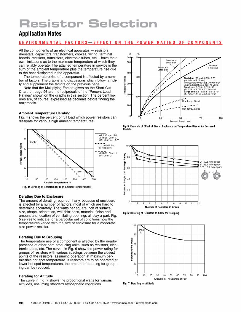
All the components of an electrical apparatus — resistors, rheostats, capacitors, transformers, chokes, wiring, terminal boards, rectifiers, transistors, electronic tubes, etc.—have their own limitations as to the maximum temperature at which they can reliably operate. The attained temperature in service is the sum of the ambient temperature plus the temperature rise due to the heat dissipated in the apparatus.
The temperature rise of a component is affected by a num-ber of factors. The graphs and discussions which follow, ampli-fy and supplement the factors on the previous page.
Note that the Multiplying Factors given on the Short Cut Chart, on page 96 are the reciprocals of the “Percent Load Ratings” shown on the graphs in this section. The percent fig-ures are, of course, expressed as decimals before finding the reciprocals.
Ambient Temperature DeratingFig. 4 shows the percent of full load which power resistors can dissipate for various high ambient temperatures.
Derating Due to EnclosureThe amount of derating required, if any, because of enclosure is affected by a number of factors, most of which are hard to determine accurately. The watts per square inch of surface, size, shape, orientation, wall thickness, material, finish and amount and location of ventilating openings all play a part. Fig. 5 serves to indicate for a particular set of conditions how the temperatures varied with the size of enclosure for a moderate size power resistor.
Derating Due to GroupingThe temperature rise of a component is affected by the nearby presence of other heat-producing units, such as resistors, elec-tronic tubes, etc. The curves in Fig. 6 show the power rating for groups of resistors with various spacings between the closest points of the resistors, assuming operation at maximum per-missible hot spot temperature. If resistors are to be operated at lower hot spot temperatures, the amount of derating for group-ing can be reduced.
Derating for AltitudeThe curve in Fig. 7 shows the proportional watts for various altitudes, assuming standard atmospheric conditions.
e N v i R o N m e N t A l F A c t o R s — e F F e c t o N t h e p o w e R R A t i N g o F c o m p o N e N t s
7
100
Per
cen
t o
f S
ing
le U
nit
Wat
tag
e R
atin
g
Number of Resistors in Group
60
20
02 4 61 3 5
80
40
2" (50.8 mm) space
8 9 10 11 12
1" (25.4 mm) space0.5" (12.7 mm) space
Fig.6: derating of Resistors to Allow for grouping
Fig. 4: derating of Resistors for high Ambient temperatures.
Fig.5: example of effect of size of enclosure on temperature Rise of An enclosed Resistor.
100
300
Percent Rated Load
100
00 25 7550
200
Tem
per
atu
re R
ise
540
500
400
300
200
100
0
°F °C
Resistor inSmall Box
Resistor inLarge Box
Box Temp., Small
Box Temp., Large
Resistorin Free Air
Resistor: 100 watt, 0.75 x 6.5"(19.05 x 165.10 mm)In unpainted 0.032" (0.813 mm) thickupainted sheet steel box, no ventsSmall box: 3.375 x 3.375 x 8"(85.725 x 85.725 x 203.20 mm)Large box: 5.813 x 5.813 x 12.75"(147.65 x 147.65 x 323.85 mm)
Fig. 7: derating for Altitude
70
100
Per
cen
t R
ated
Wat
ts
Altitude in Thousands of Feet
60
20
00 20 40 6010 30 50
80
40
5000ft.
1009080
350
100
Per
cen
t R
ated
Wat
ts
Ambient Temperature, °C
60
20
00 100 200 30050 150 250
80
40
U.L.-NEMA Std.for Resistors
Ind. & Comm. Std.Mil-R-26: Char. V.EIA: Char. E, H & V
Mil-R-26: Char. UEIA: Char. G
25°40°
275° 340°
Resistor SelectionApplication Notes
1-866-9-OHMITE • Int’l 1-847-258-0300 • Fax 1-847-574-7522 • www.ohmite.com • [email protected] 199
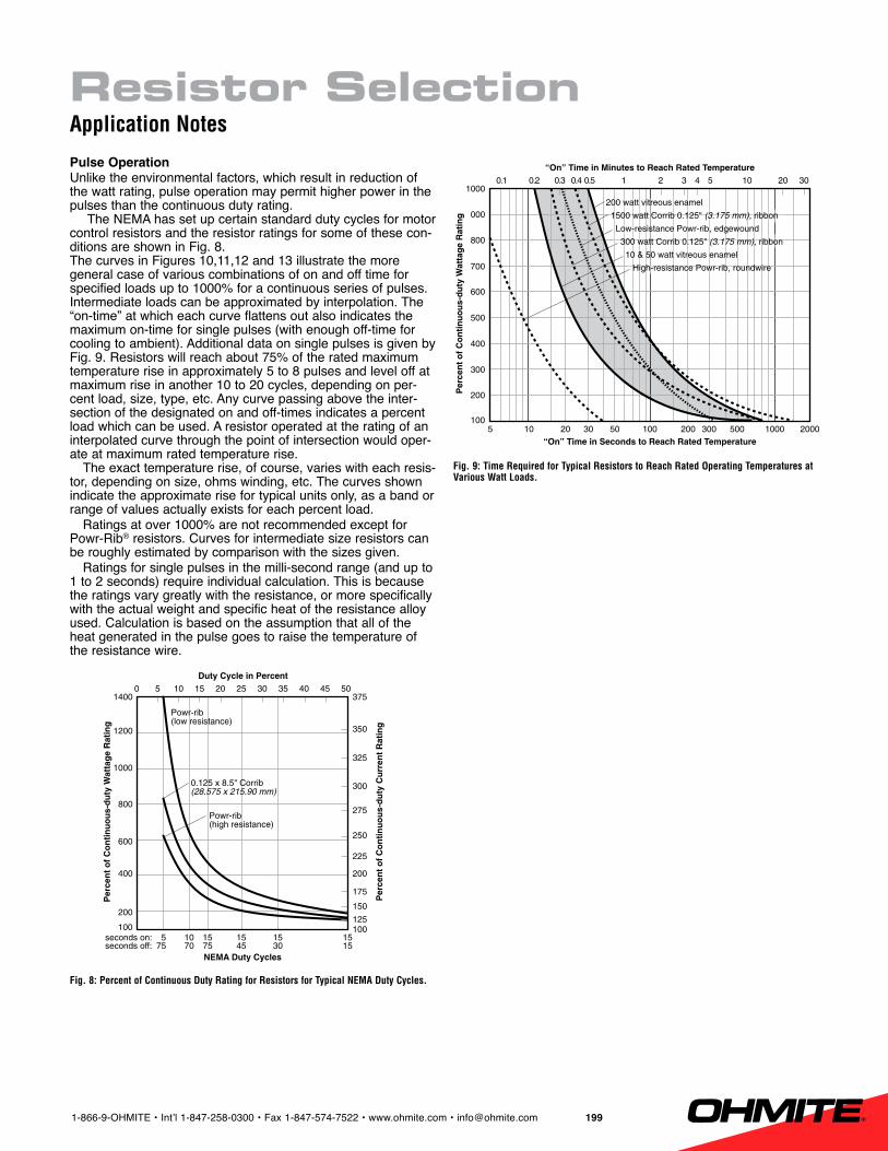
Pulse OperationUnlike the environmental factors, which result in reduction of the watt rating, pulse operation may permit higher power in the pulses than the continuous duty rating.
The NEMA has set up certain standard duty cycles for motor control resistors and the resistor ratings for some of these con-ditions are shown in Fig. 8.The curves in Figures 10,11,12 and 13 illustrate the more general case of various combinations of on and off time for specified loads up to 1000% for a continuous series of pulses. Intermediate loads can be approximated by interpolation. The “on-time” at which each curve flattens out also indicates the maximum on-time for single pulses (with enough off-time for cooling to ambient). Additional data on single pulses is given by Fig. 9. Resistors will reach about 75% of the rated maximum temperature rise in approximately 5 to 8 pulses and level off at maximum rise in another 10 to 20 cycles, depending on per-cent load, size, type, etc. Any curve passing above the inter-section of the designated on and off-times indicates a percent load which can be used. A resistor operated at the rating of an interpolated curve through the point of intersection would oper-ate at maximum rated temperature rise.
The exact temperature rise, of course, varies with each resis-tor, depending on size, ohms winding, etc. The curves shown indicate the approximate rise for typical units only, as a band or range of values actually exists for each percent load.
Ratings at over 1000% are not recommended except for Powr-Rib® resistors. Curves for intermediate size resistors can be roughly estimated by comparison with the sizes given.
Ratings for single pulses in the milli-second range (and up to 1 to 2 seconds) require individual calculation. This is because the ratings vary greatly with the resistance, or more specifically with the actual weight and specific heat of the resistance alloy used. Calculation is based on the assumption that all of the heat generated in the pulse goes to raise the temperature of the resistance wire.
Fig. 8: percent of continuous duty Rating for Resistors for typical NemA duty cycles.
Fig. 9: time Required for typical Resistors to Reach Rated operating temperatures at various watt loads.
1000
Per
cen
t o
f C
on
tin
uo
us-
du
ty W
atta
ge
Rat
ing
NEMA Duty Cycles
400
600
10010 15 155 15 15
1200
800
Powr-rib(low resistance)
0 20 4010 30 5015 355 25 45
200
1400
100
150
175
200
225
250
275
300
325
350
125
375
70 45 1575 75 30
0.125 x 8.5" Corrib(28.575 x 215.90 mm)
Powr-rib(high resistance)
seconds on:seconds off:
Per
cen
t o
f C
on
tin
uo
us-
du
ty C
urr
ent
Rat
ing
Duty Cycle in Percent
700
Per
cen
t o
f C
on
tin
uo
us-
du
ty W
atta
ge
Rat
ing
“On” Time in Seconds to Reach Rated Temperature
400
500
10010 30 2005 20 100
800
600
200 watt vitreous enamel
1500 watt Corrib 0.125" (3.175 mm), ribbon
Low-resistance Powr-rib, edgewound
300 watt Corrib 0.125" (3.175 mm), ribbon
10 & 50 watt vitreous enamel
High-resistance Powr-rib, roundwire
0.1 0.5 40.3 2 100.4 30.2 1 5
200
1000
“On” Time in Minutes to Reach Rated Temperature20 30
50 300 500 1000 2000
300
000
Resistor SelectionApplication Notes
1-866-9-OHMITE • Int’l 1-847-258-0300 • Fax 1-847-574-7522 • www.ohmite.com • [email protected]
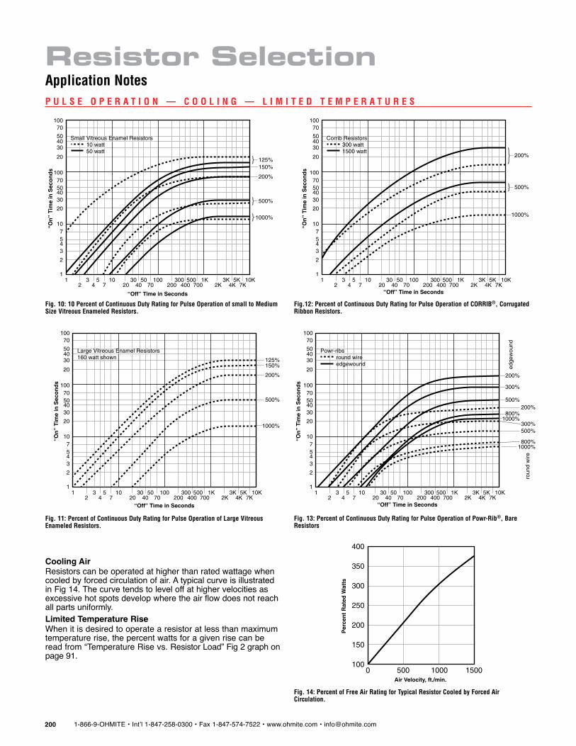
p u l s e o p e R A t i o N — c o o l i N g — l i m i t e d t e m p e R A t u R e s
Fig. 14: percent of Free Air Rating for typical Resistor cooled by Forced Air circulation.
Fig. 10: 10 percent of continuous duty Rating for pulse operation of small to medium size vitreous enameled Resistors.
Fig. 11: percent of continuous duty Rating for pulse operation of large vitreous enameled Resistors.
Fig.12: percent of continuous duty Rating for pulse operation of coRRiB®, corrugated Ribbon Resistors.
Fig. 13: percent of continuous duty Rating for pulse operation of powr-Rib®, Bare Resistors
Cooling AirResistors can be operated at higher than rated wattage when cooled by forced circulation of air. A typical curve is illustrated in Fig 14. The curve tends to level off at higher velocities as excessive hot spots develop where the air flow does not reach all parts uniformly.Limited Temperature RiseWhen it is desired to operate a resistor at less than maximum temperature rise, the percent watts for a given rise can be read from “Temperature Rise vs. Resistor Load” Fig 2 graph on page 91.
10“On
” Ti
me
in S
eco
nd
s
“Off” Time in Seconds
45
131 10
7
2
3
2 45
730 100
20 4050
70300 1K
200 400500
7003K 10K
2K 4K5K
7K
100
405070
20
30
100
4050
70
20
30
125%
Small Vitreous Enamel Resistors 10 watt 50 watt
150%
200%
500%
1000%
10“On
” Ti
me
in S
eco
nd
s
“Off” Time in Seconds
45
131 10
7
2
3
2 45
730 100
20 4050
70300 1K
200 400500
7003K 10K
2K 4K5K
7K
100
405070
20
30
100
4050
70
20
30 125%
Large Vitreous Enamel Resistors160 watt shown
150%
200%
500%
1000%
500
400
Per
cen
t R
ated
Wat
ts
Air Velocity, ft./min.
300
200
10010000 1500
350
250
150
10“On
” Ti
me
in S
eco
nd
s
“Off” Time in Seconds
45
131 10
7
2
3
2 45
730 100
20 4050
70300 1K
200 400500
7003K 10K
2K 4K5K
7K
100
405070
20
30
100
4050
70
20
30
Corrib Resistors 300 watt 1500 watt
200%
500%
1000%
roun
d w
ire
edge
wou
nd
10“On
” Ti
me
in S
eco
nd
s
“Off” Time in Seconds
45
131 10
7
2
3
2 45
730 100
20 4050
70300 1K
200 400500
7003K 10K
2K 4K5K
7K
100
405070
20
30
100
4050
70
20
30
Powr-ribs round wire edgewound
200%
500%
1000%
300%
800%200%
500%
1000%
300%
800%
Resistor SelectionApplication Notes

1-866-9-OHMITE • Int’l 1-847-258-0300 • Fax 1-847-574-7522 • www.ohmite.com • [email protected] 201
s h o R t - c u t c h A R t m e t h o d t o F i N d R e q u i R e d s i z e(as affected by application conditions)1. For each Condition, locate the relevant value on the scales below
and record the corresponding Factor (F1 to F7). Note: The Standard Free Air Condition Factor is always 1.
Four resistors, each dissipating 115 watts, are to be mounted in a group. Spacing is to be 2” surface to sur-face. Ambient to be 50°C (122°F). Enclosure to be total. Other factors standard. Determine Watt Size required.
Operation (1) On Ambient Temperature scale locate 50°C. Note and record F1 = 1.1 as shown. Locate and record the other factors.
Operation (2) Multiply the factors together = 2.64Operation (3) 115 Watts x 2.64 = 304 Watts Free Air Watt Size Rating
required for each resistor.
F1 F2 F3 F4 F5 F6 F7
50° 100% 4@2” Standard Conditions1.1 x 2.0 x 1.2 x 1 x 1 x 1 1
watts to bedissipated
factor factor factor factor factor factor factor
Temperature atinstallation includesroom temperatureplus temperaturerise due to adjacentheat sources.
Factors applyapproximately foraverage sheetmetal boxes ofdimensions suchthat watts per sq.in. of surface are inthe range of 0.2 to0.4.
Factors apply touniformly spacedbanks of parallelresistors withspacing as shown.
Factors apply toaltitudes show. Noderating is requiredfor altitudes to5000 ft. above sealevel.
Percent load forpulse operationmust first bedetermined fromgraphs and data onpage xx.
Factors areapproximationsonly. Effectivenessof cooling varieswith installation.
Low temperaturesmay be desiredbecause ofadjacentapparatus,increased stabilityor maximumreliability.
Record thewatts to bedissipated asset by yourcircuitconditions.
Standardfree air
conditions
°C F1 % F2 no. F3 ft. F4 % F5 fpm F6 °C F7
300 6.6
3.2
2.7
2.2
1.9
1.6
1.4
1.3
1.2
1.1
1.0
4.1
5.0
200
100
50
25
100 2.0
1.8
1.7
1.6
1.5
1.4
1.3
1.2
1.1
1.0
1.990
80
70
None
60
50
40
30
20
10
3 1.4
1.6
1.5
1.4
1.5
1.3
1.4
1.3
1.2
1.0
1.32
12
8
1
4
12
4
12
8
4
1.32
1.48
1.22
1.12
2" s
pace
1" s
pace
0.5"
spa
cest
d. b
rack
ets 100
1.5
1.5
1.4
1.3
1.2
1.1
1.0
90
80
70
0
60
50
40
30
20
10
1.05
1000 0.10
0.50
900
800
700
600
500
400
300
200
100 1.0
0.11
0.12
0.13
0.14
0.15
0.160.170.180.190.20
0.25
0.30
0.350.40
0.600.75
thou
sand
s of
feet
perc
ent l
oad
1500 0.27
900
800
700
600
500
400
300
200
Still 1.0
0.28
0.29
0.30
0.32
0.35
0.40
0.50
0.60
0.70
0.800.90100
1400
1300
1200
1100
1000
air v
eloc
ity: f
eet p
er m
inut
e
4013.0
300
200
1.0
10.0
8.0
6.0
4.0
3.0
1.75
1.3
1.2
1.1
100
50
7.0
5.0
2.5
2.0
1.51.4
AmbientTemperature Enclosure Grouping Altitude
PulseOperation Cooling Air
LimitedTemp. Rise
Application ConditionsWatts
ExamplE
Resistor SelectionApplication Notes
2. Multiply the Factors together.3. Multiply the Watts by the product obtained from 2 above.

1-866-9-OHMITE • Int’l 1-847-258-0300 • Fax 1-847-574-7522 • www.ohmite.com • [email protected]
t e m p e R A t u R e c o e F F i c i e N t o F R e s i s t A N c e
The resistance alloys used for all except the lowest ohmic values show such little change with temperature that in most power circuits the resistance is considered constant. Actually there may be changes at full load of -4% to +8% of the initial resistance. The change is attributed in most part to the “tem-perature coefficient of resistance” (TCR) which is the change in resistance expressed as “parts per million per degree centi-grade of temperature” (ppm/°C).
For special applications which require very constant resis-tance, it may be necessary to specify the maximum permissible TCR for the range of temperature involved. This would limit the choice of wire to only certain types of resistance alloys. The commonly known low TCR alloys in the 800 ohms per circular-mil-foot class consist largely of nickel and chromium alloyed with small amounts of aluminum and either copper or iron. Other low resistivity alloys, 294 ohms per circular-mil-foot, consist primarily of nickel and copper with only traces of other metals.
+5%
Cal
cula
ted
Ch
ang
e in
Res
ista
nce
Temperature Rise, °C
+2%
+3%
0 +200-100 +100
+6%
+4%
-50 +200+25 +1000 +300
0
+8%
Temperature Attained, °C
+300
+1%
+7%
-1%
-3%
-2%
90 ohms per C.M.F. wire+380 PPM/ϒC
675 ohms per C.M.F. wire+140 PPM/ϒC
Range for294 or 800 ohms per C.M.F. wire±20 PPM/ϒC
AmbientTemp.
Both of these wire classes are rated by the wire manu-facturers as having a TCR of 0±20ppm/°C. The expression “0±20ppm/°C” implies that, although the nominal value of the TCR is zero, the actual value may lie anywhere within the toler-ance range of –20ppm/°C to +20ppm/°C.
For other resistance wires such as the widely used nickel-chromium-iron, for example, a nominal value of +140ppm/°C is given. Actually, however, a tolerance of ±30ppm is applicable so that the TCR may range between the limits of +110 to +170ppm/°C.
Unfortunately, the TCR of a completed power resistor is generally somewhat different from that of the original wire. This is because the TCR may be affected by such factors as heat treatment during processing, and materials and methods of construction. Without special controls and precautions, the TCR over the range of 25°C to 300°C rise may increase to as much as
0±80ppm from the original 0±20ppm for certain types of wire on vitreous enameled resistors. Theoretical changes in resistance with temperature are shown in Fig. 15.
The circuit designer should carefully consider the actual needs of the circuit before specifying limits on the TCR of a desired resistor. Wherever possible it is best to select a resis-tor for a critical application so that it operates at a low tem-perature rise. This will also provide the maximum stability over a long period. For low TCR (and other) applications, Ohmite can provide resistors with an “Ohmicone” (silicone-ceramic) coating. “Ohmicone” is processed at much lower temperatures than vitreous enamel and therefore makes control of TCR and tolerance easier. Data on the TCR and other properties of vari-ous alloys is given on page 98.
Fig. 15: calculated change in resistance with nominal tc assumed constant.
Resistor SelectionApplication Notes

1-866-9-OHMITE • Int’l 1-847-258-0300 • Fax 1-847-574-7522 • www.ohmite.com • [email protected] 203
R e s i s t A N c e A l l o y s A N d u s e s
A number of different resistance alloys are used in winding resistors and rheostats as shown in Fig. 16. The general use for each alloy is indicated by the column headed, “Resistance Range for Which Used.” Whether a particular alloy can be used on a specific resistor can be estimated by dividing the given resistance by the area of the given winding space and deter-mining whether the quotient falls within the limits given hereaf-ter. The “high resistance” alloys cover the range from approxi-mately 10 to 25,000 ohms per square inch of winding area, the “low to medium” type from 5 to 400 ohms and the “very low resistance” alloys from less than an ohm to 250 ohms. It should be noted that the “Ohms per Square Inch” ranges overlap considerably, indicating that in many instances a given resis-tor could use any of several alloys. Both the upper and lower limits of the ranges are only approximate and in general can be extended somewhat when necessary.
The actual temperature coefficient of a complete resistor is generally greater than the nominal for the wire alone. The approximate change in overall resistance at full load is shown in the table.
Other AlloysIn addition to the alloys tabulated which show small changes in resistance with temperature, there are others which some-times have to be used for very low resistance units. These alloys have higher temperature coefficients, which limit their use to applications where the change in resistance with load is not important. An example is No. 60 alloy, which has a resistance of 60 ohms per circular-mil-foot and a temperature coefficient of +700ppm/°C.Ballast Wire
There are other alloys which are selected especially for their high temperature coefficient of resistance. These are used for so-called “ballast” resistors where a large change in resistance is desired with a change in load. A typical ballast wire is Nickel, which has 58 ohms/cmf and a temperature coef-ficient of +4800ppm/°C. Others are “Hytemco” and “Balco” at 120 ohms/CMF and a TC of +4500pp /°C.
*American Society for Testing Materials. Tentative Specification B267-68. **For resistor with 300°C hot spot rise from 25°C ambient except 54°C rise for Manganin. Fig. 16: table of Resistance Alloys generally used for Resistors and Rheostats.
ASTM Ohms Mean Temp Temperature Resistance Average Resis- Alloy Alloy Composition per Trade Coeff. of Res. Range for Range for tance Change Class* (Approximate) CMF Names ppm/°C TCR °C Which Used at Full Load**
Nickel base, Evanohm 1a non-magnetic 800 Karma 0 ± 20 -65 to + 250 Very high, Medi Under ± 1% Ni 75%, Cr 20% Moleculoy um and up, for to ± 2% 1b plus Al, Cu, Fe, etc. 800 Nikrothal L 0 ± 10 -65 to + 150 low temp. coeff. Iron base, magnetic Alloy 815-R 2a Fe 73%, Cr 22.5%, 800 Kanthall Dr 0 ± 20 -65 to + 200 Alternate Under ± 1% Al 4.5% (plus Co Mesaloy sometimes to ± 2% 2b in one alloy) 800 0 ± 10 0 to + 150 for Class 1
Chromel A 3a 650 Nichrome V + 80 ± 20 Nickel-Chromium Nikrothal B -65 to + 250 High and + 4 to + 5% 80% — 20% Protoloy A + 60 ± 20 medium 3b 675 Tophet C Chromel C Electroloy 4 Nickel-Chromium-Iron 675 Nichrome + 140 ± 30 -65 to + 200 High and + 5 to + 8% 60%—16%—24% Nikrothal 6 medium Tophet C Advance 5a Copel 0 ± 20 Low and low Under Copper-Nickel 300 Cupron -65 to + 150 to medium for ± 1% to ± 2% 5b 55% — 45% Cuprothal 294 0 ± 40 low temp. coeff. Neutroloy Low and low Under 6 Manganin 290 Manganin 0 ± 15 + 15 to + 35 to medium for ± 1% 13% Mn, 87% Cu low TC near 25°C to ± 2%** Copper-Nickel 180 Alloy 7 77% — 23% 180 Cuprothal 180 + 180 ± 30 -65 to + 150 Very low + 5% to + 8% Midohm Copper-Nickel 90 Alloy 9 90% — 10% 90 95 Alloy + 450 ± 50 -65 to + 150 Very low + 5% to + 10% Cuprothal 90
Resistor SelectionApplication Notes
1-866-9-OHMITE • Int’l 1-847-258-0300 • Fax 1-847-574-7522 • www.ohmite.com • [email protected]
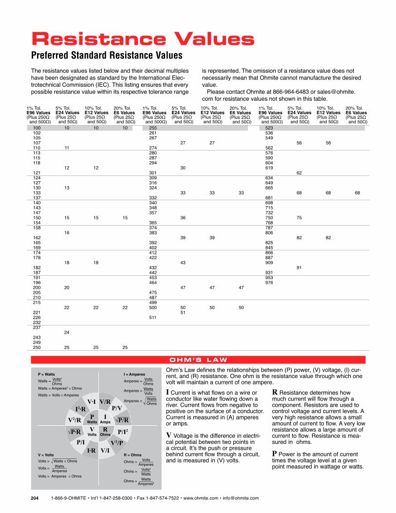
Ohm’s Law defines the relationships between (P) power, (V) voltage, (I) cur-rent, and (R) resistance. One ohm is the resistance value through which one volt will maintain a current of one ampere.
Ohm’S law
WattsP
AmpsI
VoltsV
OhmsR
√P/R
√P•R
V•II2•R
V2/R
P/II•R V/I
V2/P
P/I2
P/VV/R
R = Ohms
Ohms = VoltsAmperes
Ohms = Volts2
Watts
Ohms = WattsAmperes2
V = Volts
Volts = Amperes Ohms
Volts = Watts Ohms
Volts = WattsAmperes
P = Watts
Watts = Amperes2 Ohms
Watts = Volts Amperes
Watts = Volts2
Ohms
I = Amperes
Amperes = VoltsOhms
Amperes = WattsVolts
Amperes = WattsOhms
I Current is what flows on a wire or conductor like water flowing down a river. Current flows from negative to positive on the surface of a conductor. Current is measured in (A) amperes or amps. V Voltage is the difference in electri-cal potential between two points in a circuit. It’s the push or pressure behind current flow through a circuit, and is measured in (V) volts.
R Resistance determines how much current will flow through a component. Resistors are used to control voltage and current levels. A very high resistance allows a small amount of current to flow. A very low resistance allows a large amount of current to flow. Resistance is mea-sured in ohms. P Power is the amount of current times the voltage level at a given point measured in wattage or watts.
100 10 10 10102 105 107 110 11 113 115 118 12 12 121 124 127 130 13 133 137 140 143 147 150 15 15 15154 158 16 162 165 169 174 178 18 18 182 187 191 196 200 20 205 210 215 22 22 22221 226 232 237 24 243 249 250 25 25 25
1% Tol. E96 Values (Plus 250Ω and 500Ω)
5% Tol. E24 Values (Plus 25Ω and 50Ω)
10% Tol. E12 Values (Plus 25Ω and 50Ω)
20% Tol. E6 Values (Plus 25Ω and 50Ω)
255 261 267 27 27 274 280 287 294 30 301 309 316 324 33 33 33332 340 348 357 36 365 374 383 39 39 392 402 412 422 43 432 442 453 464 47 47 47475 487 499 500 50 50 50 51 511
523 536 549 56 56 562 576 590 604 619 62 634 649 665 68 68 68681 698 715 732 750 75 768 787 806 82 82 825 845 866 887 909 91 931 953 976
1% Tol. E96 Values (Plus 250Ω and 500Ω)
5% Tol. E24 Values (Plus 25Ω and 50Ω)
10% Tol. E12 Values (Plus 25Ω and 50Ω)
20% Tol. E6 Values (Plus 25Ω and 50Ω)
1% Tol. E96 Values (Plus 250Ω and 500Ω)
5% Tol. E24 Values (Plus 25Ω and 50Ω)
10% Tol. E12 Values (Plus 25Ω and 50Ω)
20% Tol. E6 Values (Plus 25Ω and 50Ω)
Resistance Values preferred standard Resistance valuesThe resistance values listed below and their decimal multiples have been designated as standard by the International Elec-trotechnical Commission (IEC). This listing ensures that every possible resistance value within its respective tolerance range
is represented. The omission of a resistance value does not necessarily mean that Ohmite cannot manufacture the desired value. Please contact Ohmite at 866-964-6483 or [email protected] for resistance values not shown in this table.
1-866-9-OHMITE • Int’l 1-847-258-0300 • Fax 1-847-574-7522 • www.ohmite.com • [email protected] 205
Resistor TerminologyAdjustable Resistor: A resistor so constructed that its resistance can be readily changed.*Alternating Current: A periodic current the average value of which over a period is zero. The equation for alternating current is the same as that for a periodic current except that I0=O*Ambient Temperature: The temperature of the surrounding coiling medium, such as gas or liquid, which comes into contact with heated parts of the apparatus.*Ampere: The unit of constant current which, maintained in two parallel rectilinear conduc-tors of infinite length separated by a distance of one meter, produces between these conductors a force equal to 2x10⁻⁷ mks (meter-kilogram-second) units of force per meter of length.Armature Resistor: A resistor connected in series with the armature of a motor either to limit the inrush current on starting, the gradual short circuiting of which brings the motor to normal speed, or to regulate the speed by armature-voltage control.Axiohm†: Centohm® Coated axial terminal wirewound resistor.Bracket Terminal Resistor: A resistor equipped with slotted metal end j brackets that serve as a means of mounting and connecting to the resistor.Capacitance: That property of a system of conductors and dielectrics which permits the storage of electricity when potential differ-ences exist between the conductors. Its value is expressed as the ratio of a quantity of electricity to a potential difference. A capacitance value is always positive.*Capacitor: A device, the primary purpose of which is to introduce capacitance into an elec-tric circuit. Capacitors are usually classified, according to their dielectrics, as air capacitors, mica capacitors, paper capacitors, etc.*Clearance: The shortest distance through space between two live parts, between live parts and supports or other objects, or between any live part and grounded part.Conduction: The transmission of heat or elec-tricity through, or by means of, a conductor.Conductor: A body so constructed from con-ducting material that it may be used as a carrier of electric current.*Continuous Duty: A requirement of service that demands operation at a substantially con-stant load for un indefinitely long time.*Continuous-Duty Resistor: A resistor that is capable of carrying continuously the current for which it is designed without exceeding the specified temperature rise.Continuous Rating: Continuous rating is the rating that defines the load which can be car-ried for an indefinitely long time.*Convection: Convection is the motion resulting in a fluid owing to differences of density and the action of gravity.Corrib®†: A tubular resistor consisting of an alloy resistance ribbon, crimped and edge-wound on a ceramic core, the ribbon being securely and permanently fastened to the core by vitreous enamel or cement.Creepage Distance: The shortest distance between conductors of opposite polarity or between a live part and ground as measured over the surface of the supporting material.
Current-limiting Resistor: A resistor inserted into an electric circuit to limit the flow of current to some predetermined value. Note: A current-limiting resistor, usually in series with a fuse or circuit breaker, may be employed to limit the flow of circuit or system energy at the time of a fault or short-circuit.*Dielectric Strength: The dielectric strength of an insulating material is the maximum potential gradient that the material can withstand without rupture.* It is usually specified in volts per unit thickness.Dielectric Test: A test which consists of the application of a voltage higher than the rated voltage for a specified time for the purpose of determining the adequacy against breakdown of insulating materials and spacings under nor-mal conditions.*Direct Current: A unidirectional current in which the changes in value are either zero or so small that they may be neglected. A given current would be considered a direct current in some applications, but would not necessarily be so considered in other applications.*Dividohm®†: A resistor with a bare side and clamp for adjustment.Edgeohm†: A high-current resistor made of an alloy resistance ribbon wound on edge form-ing an oval-shaped coil supported by grooved insulators which space adjacent turns and insulate them from the support bars. Support bars are secured to steel end pieces forming a sturdy resistor suitable for continuous-and-intermittent-duty applications.EIA: Electronic Industries Alliance.Electromotive Force: The electromotive force is the agency causing the flow of current in a circuit. It is the electrical pressure (or drop) measured in volts.Farad: The unit of capacitance of an electric condenser in which a charge of one coulomb produces a difference of potential of one volt between the poles of the capacitor.Ferrule Resistor: A resistor supplied with fer-rule terminals for mounting in standard fuse clips.Field Discharge Switch: A switch usually of the knife blade type having auxiliary contacts for connecting the field of a generator or motor across a resistor (field discharge) at the instant preceding the opening of the switch.Fixed Resistor: A resistor designed to intro-duce only one set amount of resistance into an electrical circuit.Henry: The unit of inductance of a closed cir-cuit in which an electromotive force of one volt is produced when the electric current traversing the circuit varies uniformly at the rate of one ampere per second.Hot Spot: The point or location of maximum temperature on the external surface of a resis-tor.Inductance: The (scalar) property of an elec-tric circuit or of two neighboring circuits which determines the electromotive force induced in one of the circuits by a change of current in either of them.*Impedance: The apparent resistance of an AC circuit, being the combination of both the resistance and reactance. It is equal to the ratio of the value of the EMF between the terminals to the current, there being no source of power
in the portion under consideration. The unit of impedance is the ohm and is represented by Z.Intermittent Duty: A requirement of service that demands operation for alternate intervals of (1) load and no-load; or (2) load and rest; or (3) load, no-load and rest; such alternate inter-vals being definitely specified.*Intermittent-Duty Resistor: A resistor capable of carrying for a short period of time the high overload current for which it is designed without exceeding the specified temperature rise.Machine-Duty Resistor: A resistor for use in the armature or rotor circuit of a motor in which the armature current is almost constant.Mega Ohm: A unit of resistance equal to one million ohms.MIL Resistor: A resistor built in accordance with Joint Army-Navy specifications.Multi-Section Resistor: A resistor having two or more electrically independent sections.NEC: The National Electrical Code is the stan-dard of the National Board of Fire Underwriters for electric wiring and apparatus as recom-mended by the National Fire Protection Association and approved by the American Standards Association.NEDA: National Electronic Distributors Association.NEMA: The National Electrical Manufacturers Association, a non-profit trade association, supported by the manufacturers of electrical apparatus and supplies. NEMA is engaged in standardization to facilitate understanding between the manufacturers and users of elec-trical products.Nominal Diameter: As applied to tubular resis-tors, this is the diameter of the ceramic tube expressed in inches and/or fractions thereof.Nominal Length: As applied to tubular resis-tors, this is the length of the resistor base or core expressed in inches and/or fractions thereof.Non-Inductive Resistor: A non-inductive power resistor is one in which the inductance and distributed capacitance are reduced to an absolute minimum.Ohm: A unit of resistance defined as the resis-tance at 0°C of a column of mercury of uniform cross-section having a length of 106.3 centime-ters and a mass of 14.4 grams.Ohmmeter: An instrument for measuring elec-tric resistance that is provided with a scale graduated in ohms.Periodic Duty: A type of intermittent duty in which the load conditions are regularly recur-rent.*Periodic Rating: The rating which defines the load which can be carried for the alternate periods of load and rest specified in the rating, the apparatus starting cold and for the total time specified in the rating without causing any of the specified limitations to be exceeded.*Power: The time rate of transferring or trans-forming energy; the rate of doing work or expending energy.Power Resistor: A resistor capable of dissipat-ing 5 watts or more.Rating: A designated limit of operating char-acteristics of a machine, apparatus or device, based on definite conditions.
1-866-9-OHMITE • Int’l 1-847-258-0300 • Fax 1-847-574-7522 • www.ohmite.com • [email protected]
Resistor Terminology
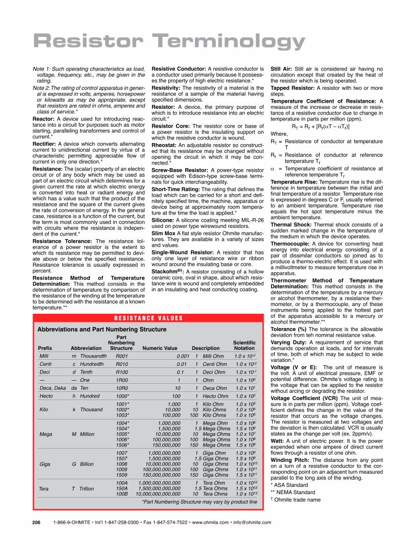
R e s i s t a n c e V a l u e s
Abbreviations and Part Numbering Structure
Note 1: Such operating characteristics as load, voltage, frequency, etc., may be given in the rating.
Note 2: The rating of control apparatus in gener-al is expressed in volts, amperes, horsepower or kilowatts as may be appropriate, except that resistors are rated in ohms, amperes and class of service.*
Reactor: A device used for introducing reac-tance into a circuit for purposes such as motor starting, paralleling transformers and control of current.*Rectifier: A device which converts alternating current to unidirectional current by virtue of a characteristic permitting appreciable flow of current in only one direction.*Resistance: The (scalar) property of an electric circuit or of any body which may be used as part of an electric circuit which determines for a given current the rate at which electric energy is converted into heat or radiant energy and which has a value such that the product of the resistance and the square of the current gives the rate of conversion of energy. In the general case, resistance is a function of the current, but the term is most commonly used in connection with circuits where the resistance is indepen-dent of the current.*Resistance Tolerance: The resistance tol-erance of a power resistor is the extent to which its resistance may be permitted to devi-ate above or below the specified resistance. Resistance tolerance is usually expressed in percent.Resistance Method of Temperature Determination: This method consists in the determination of temperature by comparison of the resistance of the winding at the temperature to be determined with the resistance at a known temperature.**
Resistive Conductor: A resistive conductor is a conductor used primarily because it possess-es the property of high electric resistance.*Resistivity: The resistivity of a material is the resistance of a sample of the material having specified dimensions.Resistor: A device, the primary purpose of which is to introduce resistance into an electric circuit.*Resistor Core: The resistor core or base of a power resistor is the insulating support on which the resistive conductor is wound.Rheostat: An adjustable resistor so construct-ed that its resistance may be changed without opening the circuit in which it may be con-nected.*Screw-Base Resistor: A power-type resistor equipped with Edison-type screw-base termi-nals for quick interchangeability.Short-Time Rating: The rating that defines the load which can be carried for a short and defi-nitely specified time, the machine, apparatus or device being at approximately room tempera-ture at the time the load is applied.*Silicone: A silicone coating meeting MIL-R-26 used on power type wirewound resistors.Slim Mox A flat style resistor Ohmite manufac-tures. They are available in a variety of sizes and values.Single-Wound Resistor: A resistor that has only one layer of resistance wire or ribbon wound around the insulating base or core.Stackohm®†: A resistor consisting of a hollow ceramic core, oval in shape, about which resis-tance wire is wound and completely embedded in an insulating and heat conducting coating.
Still Air: Still air is considered air having no circulation except that created by the heat of the resistor which is being operated.Tapped Resistor: A resistor with two or more steps.Temperature Coefficient of Resistance: A measure of the increase or decrease in resis-tance of a resistive conductor due to change in temperature in parts per million (ppm). RT = Rr + [Rr(αT – αTr)]Where,RT = Resistance of conductor at temperature
TRr = Resistance of conductor at reference
temperature Trα = Temperature coefficient of resistance at
reference temperature TrTemperature Rise: Temperature rise is the dif-ference in temperature between the initial and final temperature of a resistor. Temperature rise is expressed in degrees C or F, usually referred to an ambient temperature. Temperature rise equals the hot spot temperature minus the ambient temperature.Thermal Shock: Thermal shock consists of a sudden marked change in the temperature of the medium in which the device operates.Thermocouple: A device for converting heat energy into electrical energy consisting of a pair of dissimilar conductors so joined as to produce a thermo-electric effect. It is used with a millivoltmeter to measure temperature rise in apparatus.Thermometer Method of Temperature Determination: This method consists in the determination of the temperature by a mercury or alcohol thermometer, by a resistance ther-mometer, or by a thermocouple, any of these instruments being applied to the hottest part of the apparatus accessible to a mercury or alcohol thermometer.**Tolerance (%) The tolerance is the allowable deviation from teh nominal resistance value.Varying Duty: A requirement of service that demands operation at loads, and for intervals of time, both of which may be subject to wide variation.*Voltage (V or E): The unit of measure is the volt. A unit of electrical pressure, EMF or potential difference. Ohmite’s voltage rating is the voltage that can be applied to the resistor without arcing or degrading the resistor.Voltage Coefficient (VCR) The unit of mea-sure is in parts per million (ppm). Voltage coef-ficient defines the change in the value of the resistor that occurs as the voltage changes. The resistor is measured at two voltages and the deviation is then calculated. VCR is usually states as the change per volt (ex. 2ppm/v).Watt: A unit of electric power. It is the power expended when one ampere of direct current flows through a resistor of one ohm.Winding Pitch: The distance from any point on a turn of a resistive conductor to the cor-responding point on an adjacent turn measured parallel to the long axis of the winding.* ASA Standard** NEMA Standard† Ohmite trade name
DescriptionPrefix Abbreviation
PartNumberingStructure Numeric Value
Milli m Thousandth
Centi c Hundredth
Deci d Tenth
— — One
Deca, Deka da Ten
Hecto h Hundred
Kilo k Thousand
Tera T Trillion
Giga G Billion
Mega M Million
R001 0.001 1 Milli Ohm
R010 0.01 1 Centi Ohm
R100 0.1 1 Deci Ohm
1R00 1 1 Ohm
10R0 10 1 Deca Ohm
1000* 100 1 Hecto Ohm
1001* 1,000 1 Kilo Ohm1002* 10,000 10 Kilo Ohms1003* 100,000 100 Kilo Ohms
1004* 1,000,000 1 Mega Ohm1504* 1,500,000 1.5 Mega Ohms1005* 10,000,000 10 Mega Ohms1006* 100,000,000 100 Mega Ohms1506* 150,000,000 150 Mega Ohms
1007 1,000,000,000 1 Giga Ohm1507 1,500,000,000 1.5 Giga Ohms1008 10,000,000,000 10 Giga Ohms1009 100,000,000,000 100 Giga Ohms1509 150,000,000,000 150 Giga Ohms
100A 1,000,000,000,000 1 Tera Ohm150A 1,500,000,000,000 1.5 Tera Ohms100B 10,000,000,000,000 10 Tera Ohms
*Part Numbering Structure may vary by product line
ScientificNotation
1.0 x 10⁻³
1.0 x 10⁻²
1.0 x 10⁻¹
1.0 x 100
1.0 x 101
1.0 x 10²
1.0 x 10³
1.0 x 10⁴
1.0 x 10⁵
1.0 x 10⁶
1.5 x 10⁶
1.0 x 10⁷
1.0 x 10⁸
1.5 x 10⁸
1.0 x 10⁹
1.5 x 10⁹
1.0 x 10¹⁰
1.0 x 10¹¹
1.5 x 10¹¹
1.0 x 10¹²
1.5 x 10¹²
1.0 x 10¹³