resistors - wide resistance range - vishay - … · resistors - wide resistance range with...
TRANSCRIPT
Res
isto
rs -
Wid
e R
esis
tanc
e R
ange
With Non-Linear Resistors
TABLE OF CONTENTS
Using PTC - Positive Temperature Coefficient Thermistors ................................................02
PTC Overload Protection Principles ....................................................................................02
Using NTC – Negative Temperature Coefficient Thermistors ..............................................03
Examples of NTC Circuit Protection....................................................................................03
Rate of Rise Heat Detecting Fire Alarm ...............................................................................04
Using Through-Hole Varistors .............................................................................................05
RESOuRCES• For technical questions contact [email protected]
THis DOCUmENT is sUbjECT TO CHANgE WiTHOUT NOTiCE. THE PRODUCTs DEsCRibED HEREiN AND THis DOCUmENT ARE sUbjECT TO sPECiFiC DisCLAimERs, sET FORTH AT www.vishay.com/doc?91000
CIRCuIT PROTECTION
INN
OVA
TI
ON AND TECHNO
LO
GY
1 9 6 2 - 2 0 1 2
V i s H Ay i N T E R T E C H N O LO gy, i N C .
VmN-PL0436-12051/6
Discrete Semiconductors and Passive ComponentsOne of the World’s Largest Manufacturers of
CAPAbiLiTiEs
PTC and NTC Thermistors, Through-Hole Varistors
Res
isto
rs -
Wid
e R
esis
tanc
e R
ange
With Non-Linear Resistors
using PTC – Positive Temperature Coefficient ThermistorsThe electrical resistance of ceramic PTC (positive temperature coefficient) thermistors increases exponentially at the so called switching temperature or Ts. This typical characteristic makes PTC thermistors very useful components for several application areas such as voltage and current overload protection, over-temperature protection, inrush current generation, time delay, energy discharge, and as a ceramic self-limiting heating element. As an overload protective element, PTC thermistors are used in a wide range of circuits, including line cards, set-top boxes, and private automated branch exchanges in telecom applications; airbag and temperature control devices in automobiles; power supplies, transformers, DC motors and small domestic appliances; and in other consumer products.
PTC Overload Protection PrinciplesFeatures
• Different voltages in function of the application: 30 V to 60 V, 145 V, 265 V, 600 V
• several mechanical executions: pellets, through hole leaded, smD
• Wide range of trip and hold currents: from 10 mA to 4.5 A minimum trip currents
• Wide range of resistance: from 0.3 Ω to 5 kΩ• small ratio between trip and hold currents
(itrip/ihold = 1.5 at 25 °C)• High maximum inrush current: up to 30 A• UL approved series
Part NumbersGeneral overload protection:• 30 V to 60 V series: PTCCL..H....bE series (UL approved)• 145 V series: PTCCL..H...FbE (UL approved)• 265 V series: PTCCL..H...HbE (UL approved)• 600 V series: PTCCL..H...sbE• smD series: PTCTZ
Over-temperature:• Tn 70 ºC to 140 ºC: PTCss series (smD, UL approved)• Tn 70 °C to 150 °C: PTCsL series
Telecom protection:• general leaded: PTCTL• smD: PTCTZ and PTCTT
Vsupply Load
PTC
0.1
1
10
100
0 2000 4000 6000 8000 10000
I (mA)
trip time (s)
Figure 1
Figure 3
Temp25 ºC
Lo
g R
Rmin
2Rmin
Ts
Log V
Lo
g I
Ihold
Itrip
Vmax
NormalOperating
Zone
ProtectingZone
Figure 2
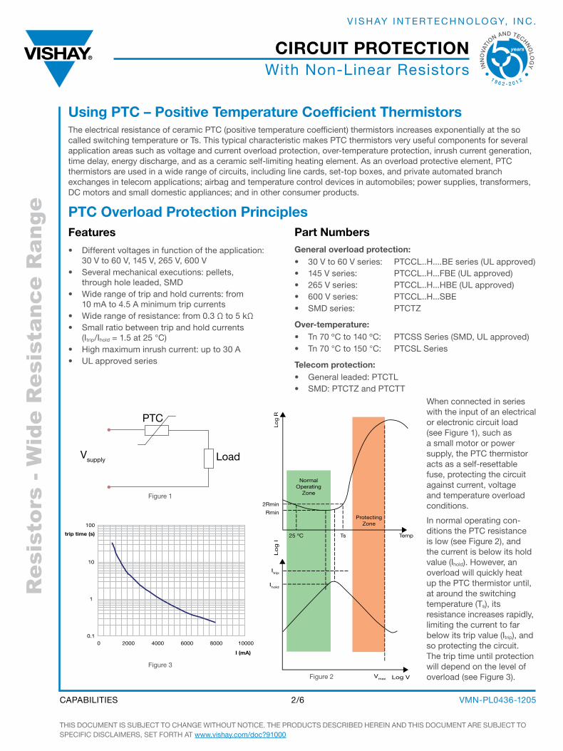
When connected in series with the input of an electrical or electronic circuit load (see Figure 1), such as a small motor or power supply, the PTC thermistor acts as a self-resettable fuse, protecting the circuit against current, voltage and temperature overload conditions.
in normal operating con-ditions the PTC resistance is low (see Figure 2), and the current is below its hold value (ihold). However, an overload will quickly heat up the PTC thermistor until, at around the switching temperature (Ts), its resistance increases rapidly, limiting the current to far below its trip value (itrip), and so protecting the circuit. The trip time until protection will depend on the level of overload (see Figure 3).
THis DOCUmENT is sUbjECT TO CHANgE WiTHOUT NOTiCE. THE PRODUCTs DEsCRibED HEREiN AND THis DOCUmENT ARE sUbjECT TO sPECiFiC DisCLAimERs, sET FORTH AT www.vishay.com/doc?91000
VmN-PL0436-12052/6CAPAbiLiTiEs
CIRCuIT PROTECTION
INN
OVA
TI
ON AND TECHNO
LO
GY
1 9 6 2 - 2 0 1 2
V i s H Ay i N T E R T E C H N O LO gy, i N C .
Res
isto
rs -
Wid
e R
esis
tanc
e R
ange
With Non-Linear Resistors
using NTC – Negative Temperature Coefficient ThermistorsThe electrical resistance of NTC (negative temperature coefficient) thermistors increases as the ambient temperature decreases, and decreases when temperature increases. NTC thermistors are used for overtemperature protection in PCs, power supplies, and motherboards; Li-ion battery protection in fast chargers; and in digital scan cameras, fire and smoke detectors, TCXOs, and other automotive, consumer, and industrial applications. They are generally included in a voltage divider or Wheatstone bridges and can provide a measuring voltage to analog-digital converters. They also allow to control the temperature compensation of displays and regulation of temperature with opamps or more complex iCs.
Features for Circuit Protection:
• Leaded and smD versions in case sizes from 0402 to 1206• Large resistance range: from 3.3 Ω to 470 kΩ• Temperature range: - 55 °C to + 155 °C• smD termination: 100 % sn over Nickel• Customized types available upon request
Examples of NTC Circuit ProtectionPC Cooling Fan
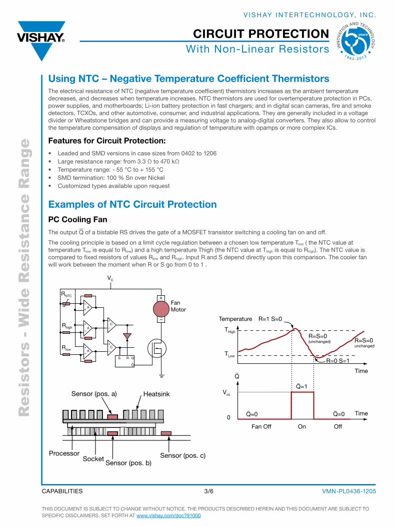
The output Q of a bistable Rs drives the gate of a mOsFET transistor switching a cooling fan on and off.
The cooling principle is based on a limit cycle regulation between a chosen low temperature Tlow ( the NTC value at temperature Tlow is equal to Rlow) and a high temperature Thigh (the NTC value at Thigh is equal to Rhigh). The NTC value is compared to fixed resistors of values Rlow and Rhigh. input R and s depend directly upon this comparison. The cooler fan will work between the moment when R or s go from 0 to 1 .
FanMotor
VC
RNTC
A
AC
C
QS R
A
+
+
++
+
–
–
–
–
–
Rhigh
Rlow
+
–
Q
HeatsinkSensor (pos. a)
Sensor (pos. b)Sensor (pos. c)Processor
Socket
R=1 S=0
R=0 S=1
Time
Time
Temperature
Q=0
Q=1
Q=0
R=S=0(unchanged) R=S=0
unchanged
THigh
TLow
Q
Vcc
Fan Off OffOn
0
THis DOCUmENT is sUbjECT TO CHANgE WiTHOUT NOTiCE. THE PRODUCTs DEsCRibED HEREiN AND THis DOCUmENT ARE sUbjECT TO sPECiFiC DisCLAimERs, sET FORTH AT www.vishay.com/doc?91000
VmN-PL0436-12053/6CAPAbiLiTiEs
CIRCuIT PROTECTION
INN
OVA
TI
ON AND TECHNO
LO
GY
1 9 6 2 - 2 0 1 2
V i s H Ay i N T E R T E C H N O LO gy, i N C .
Res
isto
rs -
Wid
e R
esis
tanc
e R
ange
With Non-Linear Resistors
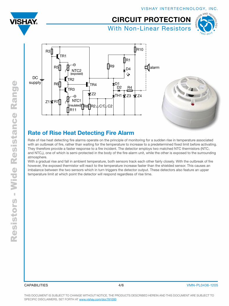
Rate of Rise Heat Detecting Fire AlarmRate of rise heat detecting fire alarms operate on the principle of monitoring for a sudden rise in temperature associated with an outbreak of fire, rather than waiting for the temperature to increase to a predetermined fixed limit before activating. They therefore provide a faster response to a fire incident. The detector employs two matched NTC thermistors (NTC1 and NTC2), one of which is semi-protected in the body of the fire-alarm unit, while the other is exposed to the surrounding atmosphere. With a gradual rise and fall in ambient temperature, both sensors track each other fairly closely. With the outbreak of fire however, the exposed thermistor will react to the temperature increase faster than the shielded sensor. This causes an imbalance between the two sensors which in turn triggers the detector output. These detectors also feature an upper temperature limit at which point the detector will respond regardless of rise time.
R11
TH1-Θ
-Θ
NTC1(insulated)
TR3R6
TR2
NTC2(exposed)
R5
TR1R3
R7Z1
Z2
R8 R2
TR4
C1 C2
D1D2
Z3 Z4
R4
D4
R1
R10
R9 alarm
DC supply
THis DOCUmENT is sUbjECT TO CHANgE WiTHOUT NOTiCE. THE PRODUCTs DEsCRibED HEREiN AND THis DOCUmENT ARE sUbjECT TO sPECiFiC DisCLAimERs, sET FORTH AT www.vishay.com/doc?91000
VmN-PL0436-12054/6CAPAbiLiTiEs
CIRCuIT PROTECTION
INN
OVA
TI
ON AND TECHNO
LO
GY
1 9 6 2 - 2 0 1 2
V i s H Ay i N T E R T E C H N O LO gy, i N C .
Res
isto
rs -
Wid
e R
esis
tanc
e R
ange
With Non-Linear Resistors
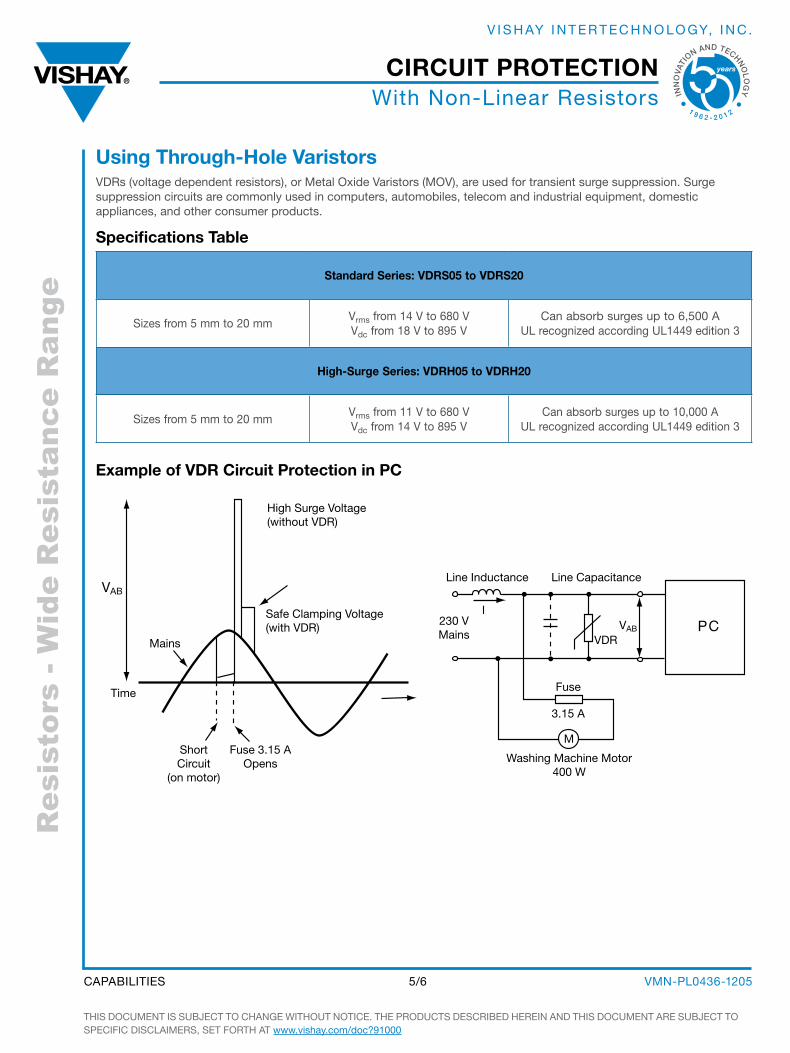
Standard Series: VDRS05 to VDRS20
sizes from 5 mm to 20 mmVrms from 14 V to 680 VVdc from 18 V to 895 V
Can absorb surges up to 6,500 AUL recognized according UL1449 edition 3
High-Surge Series: VDRH05 to VDRH20
sizes from 5 mm to 20 mmVrms from 11 V to 680 VVdc from 14 V to 895 V
Can absorb surges up to 10,000 AUL recognized according UL1449 edition 3
using Through-Hole VaristorsVDRs (voltage dependent resistors), or metal Oxide Varistors (mOV), are used for transient surge suppression. surge suppression circuits are commonly used in computers, automobiles, telecom and industrial equipment, domestic appliances, and other consumer products.
Specifications Table
Example of VDR Circuit Protection in PC
VAB
Mains
Time
ShortCircuit
(on motor)
Fuse 3.15 AOpens
Safe Clamping Voltage(with VDR)
High Surge Voltage(without VDR)
PC
Line Capacitance
I
VDR
Line Inductance
230 VMains
Washing Machine Motor400 W
Fuse
3.15 A
VAB
M
THis DOCUmENT is sUbjECT TO CHANgE WiTHOUT NOTiCE. THE PRODUCTs DEsCRibED HEREiN AND THis DOCUmENT ARE sUbjECT TO sPECiFiC DisCLAimERs, sET FORTH AT www.vishay.com/doc?91000
VmN-PL0436-12055/6CAPAbiLiTiEs
CIRCuIT PROTECTION
INN
OVA
TI
ON AND TECHNO
LO
GY
1 9 6 2 - 2 0 1 2
V i s H Ay i N T E R T E C H N O LO gy, i N C .
Res
isto
rs -
Wid
e R
esis
tanc
e R
ange
With Non-Linear Resistors
THis DOCUmENT is sUbjECT TO CHANgE WiTHOUT NOTiCE. THE PRODUCTs DEsCRibED HEREiN AND THis DOCUmENT ARE sUbjECT TO sPECiFiC DisCLAimERs, sET FORTH AT www.vishay.com/doc?91000
VmN-PL0436-12056/6CAPAbiLiTiEs
CIRCuIT PROTECTION
INN
OVA
TI
ON AND TECHNO
LO
GY
1 9 6 2 - 2 0 1 2
V i s H Ay i N T E R T E C H N O LO gy, i N C .
THE AmERICAS
uNITED STATESVisHAy AmERiCAs ONE gREENWiCH PLACE sHELTON, CT 06484 UNiTED sTATEs PH: +1-402-563-6866 FAX: +1-402-563-6296
ASIA
SINGAPOREVisHAy iNTERTECHNOLOgy AsiA PTE LTD.37A TAmPiNEs sTREET 92 #07-00siNgAPORE 528886 PH: +65-6788-6668 FAX: +65-6788-0988
P.R. CHINAVisHAy CHiNA CO., LTD.15D, sUN TONg iNFOPORT PLAZA55 HUAi HAi WEsT ROADsHANgHAi 200030 P.R. CHiNAPH: +86-21-5258 5000FAX: +86-21-5258 7979
jAPANVisHAy jAPAN CO., LTD.sHibUyA PREsTigE bLDg. 4F 3-12-22, sHibUyA sHibUyA-kU TOkyO 150-0002 jAPAN PH: +81-3-5466-7150 FAX: +81-3-5466-7160
EuROPE
GERmANyVisHAy ELECTRONiC gmbHDR.-FELiX-ZANDmAN-PLATZ 1 95100 sELb gERmANy PH: +49-9287-71-0 FAX: +49-9287-70435 FRANCEVisHAy s.A.199, bD DE LA mADELEiNE 06003 NiCE, CEDEX 1 FRANCE PH: +33-4-9337-2727 FAX: +33-4-9337-2726 uNITED kINGDOmVisHAy LTD.sUiTE 6C, TOWER HOUsEsT. CATHERiNE’s COURTsUNDERLAND ENTERPRisE PARksUNDERLAND sR5 3Xj UNiTED kiNgDOmPH: +44-191-516-8584FAX: +44-191-549-9556
WORLDWiDE sALEs CONTACTs