resonance in ac circuits - hainepages-* resonance in ac circuits the rms current in an lrc series...
TRANSCRIPT
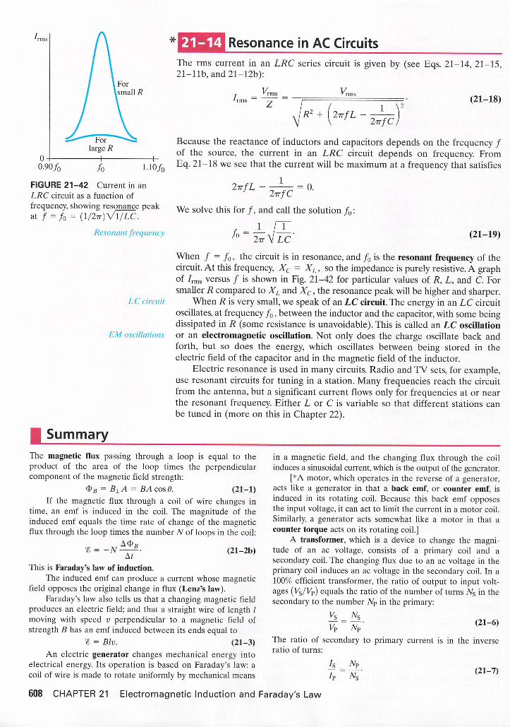
-* Resonance in AC CircuitsThe rms current in an LRC series circuit is given by (see Eqs. 21-14, 21-15,21-llb, and 21-12b):
-'rmsv„ v„
<R2 + I 2tt/L —y2 i r f C j
(21-18)
Because the reactance of inductors and capacitors depends on the frequency /of the source, the current in an LRC circuit depends on frequency. FromEq. 21-18 we see that the current will be maximum at a frequency that satisfies
FIGURE 21-42 Current in anLRC circuit as a function offrequency, showing resonance peakat / = /o= (1/277) VT/LC.
Resonant frequency
2-nfL1 = 0.
l i r f CWe solve this for /, and call the solution f0:
2tt V LC'/ o (21-19)
LC circuit
EM oscillations
When / = /0, the circuit is in resonance, and fQ is the resonant frequency of thecircuit. At this frequency, Xc = XL, so the impedance is purely resistive. A graphof 7rms versus / is shown in Fig. 21-42 for particular values of R, L, and C. Forsmaller R compared to XL and Xc, the resonance peak will be higher and sharper.
When R is very small, we speak of an LC circuit. The energy in an LC circuitoscillates, at frequency f0, between the inductor and the capacitor, with some beingdissipated in R (some resistance is unavoidable). This is called an LC oscillationor an electromagnetic oscillation. Not only does the charge oscillate back andforth, but so does the energy, which oscillates between being stored in theelectric field of the capacitor and in the magnetic field of the inductor.
Electric resonance is used in many circuits. Radio and TV sets, for example,use resonant circuits for tuning in a station. Many frequencies reach the circuitfrom the antenna, but a significant current flows only for frequencies at or nearthe resonant frequency. Either L or C is variable so that different stations canbe tuned in (more on this in Chapter 22).
| SummaryThe magnetic flux passing through a loop is equal to theproduct of the area of the loop times the perpendicularcomponent of the magnetic field strength:
< S > B = B ± A = B A c o s 8 . ( 2 1 - 1 )If the magnetic flux through a coil of wire changes in
time, an emf is induced in the coil. The magnitude of theinduced emf equals the time rate of change of the magneticflux through the loop times the number TV of loops in the coil:
A<$>BN ~ A t ' ( 2 1 _ 2 b )
This is Faraday's law of induction.The induced emf can produce a current whose magnetic
field opposes the original change in flux (Lenz's law).Faraday's law also tells us that a changing magnetic field
produces an electric field; and that a straight wire of length /moving with speed v perpendicular to a magnetic field ofstrength B has an emf induced between its ends equal to
% = B l v . ( 2 1 - 3 )An electric generator changes mechanical energy into
electrical energy. Its operation is based on Faraday's law: acoil of wire is made to rotate uniformly by mechanical means
in a magnetic field, and the changing flux through the coilinduces a sinusoidal current, which is the output of the generator.
[*A motor, which operates in the reverse of a generator,acts like a generator in that a back emf, or counter emf, isinduced in its rotating coil. Because this back emf opposesthe input voltage, it can act to limit the current in a motor coil.Similarly, a generator acts somewhat like a motor in that acounter torque acts on its rotating coil.]
A transformer, which is a device to change the magnitude of an ac voltage, consists of a primary coil and asecondary coil. The changing flux due to an ac voltage in theprimary coil induces an ac voltage in the secondary coil. In a100% efficient transformer, the ratio of output to input voltages (Vs/Vp) equals the ratio of the number of turns Ns in thesecondary to the number N? in the primary:
V s N sv ? = %■ < 2 1 - 6 >
The ratio of secondary to primary current is in the inverseratio of turns:
hI?
N?w (21-7)
608 CHAPTER 21 Electromagnetic Induction and Faraday's Law

Microphones, ground fault circuit interrupters, seismographs, and read/write heads for computer drives and taperecorders are applications of electromagnetic induction.
[*A changing current in a coil of wire will produce achanging magnetic field that induces an emf in a second coilplaced nearby. The mutual inductance, M, is defined by
« 2 = - m 4 t - < 2 i - 8 > ]At
[*Within a single coil, the changing B due to a changingcurrent induces an opposing emf, % so a coil has aself-inductance L defined by
. A/At (21-9)]
[*The energy stored in an inductance L carrying current Iis given by U = 1 LI2. This energy can be thought of as beingstored in the magnetic field of the inductor. The energy densityU in any magnetic field B is given by
u = \ — ■ ( 2 1 - 1 0 ) ]
[*When an inductance L and resistor R are connected inseries to a source of emf, V, the current rises as
where t = L/R is the time constant. If the battery issuddenly switched out of the LR circuit, the current dropsexponentially, I = Imaxe~ •]
[*Inductive and capacitive reactance. X. defined as forresistors, is the proportionality constant between voltage andcurrent (either the rms or peak values). Across an inductor,
V = I X L , ( 2 1 - l l a )and across a capacitor,
V = I X C . ( 2 1 - 1 2 a )The reactance of an inductor increases with frequency
X L = 2 7 7 - / L , ( 2 1 - l l b )whereas the reactance of a capacitor decreases with frequency /,
1X r
2l t fC(21-12b)
The current through a resistor is always in phase with thevoltage across it, but in an inductor, the current lags the voltageby 90°, and in a capacitor the current leads the voltage by 90°.]
[*In an LRC series circuit, the total impedance Z isdefined by the equivalent of V = IR for resistance, namely,
V0 = IQZ or v„ / 7 - (21-14)7 is given by
Z = \ J R2 + (XL - Xc f . (21 -15a) ]
[*An LRC series circuit resonates at a frequency given by
f ^ i ^ c - ( 2 1 - 1 9 )The rms current in the circuit is largest when the appliedvoltage has a frequency equal to /o.]
| Questions1. What would be the advantage, in Faraday's experiments
(Fig. 21-1), of using coils with many turns?2. What is the difference between magnetic flux and
magnetic field?3. Suppose you are holding a circular ring of wire and suddenly
thrust a magnet, south pole first, away from you toward thecenter of the circle. Is a current induced in the wire? Is acurrent induced when the magnet is held steady within thering? Is a current induced when you withdraw the magnet?In each case, if your answer is yes, specify the direction.
4. Two loops of wire are moving in the vicinity of a verylong straight wire carrying a steady current as shown inFig. 21-43. Find the direction of the induced current ineach loop.
/
FIGURE 21-43Question 4.
O ^5. Suppose you are looking along a line through the centers
of two circular (but separate) wire loops, one behind theother. A battery is suddenly connected to the front loop,establishing a clockwise current, (a) Will a current beinduced in the second loop? (b) If so, when does thiscurrent start? (c) When does it stop? (d) In what directionis this current? (e) Is there a force between the twoloops? (/) If so, in what direction?
6. In Fig. 21-44, determine the direction of the inducedcurrent in resistor RA when (a) coil B is moved towardcoil A. (b) when coil B is moved away from A, (c) whenthe resistance RB is increased.
Coil A
L ^ A A / V | h
FIGURE 21-44 Question 6.
7. In situations where a small signal must travel over adistance, a "shielded cable" is used in which the signalwire is surrounded by an insulator and then enclosed by acylindrical conductor carrying the return current. Why is a"shield" necessary?
8. What is the advantage of placing the two insulated electric wires carrying ac close together or even twisted abouteach other?
"9. Explain why, exactly, the lights may dim briefly when arefrigerator motor starts up. When an electric heater isturned on, the lights may stay dimmed as long as theheater is on. Explain the difference.
Questions 609
* 10. Use Figs. 21-15 and 21-17 plus the right-hand rules toshow why the counter torque in a generator opposes themotion.
* 11. Will an eddy current brake (Fig. 21-20) work on a copperor aluminum wheel, or must the wheel be ferromagnetic?Explain.
* 12. It has been proposed that eddy currents be used to helpsort solid waste for recycling. The waste is first groundinto tiny pieces and iron removed with a dc magnet. Thewaste then is allowed to slide down an incline overpermanent magnets. How will this aid in the separation ofnonferrous metals (Al, Cu, Pb, brass) from nonmetallicmaterials?
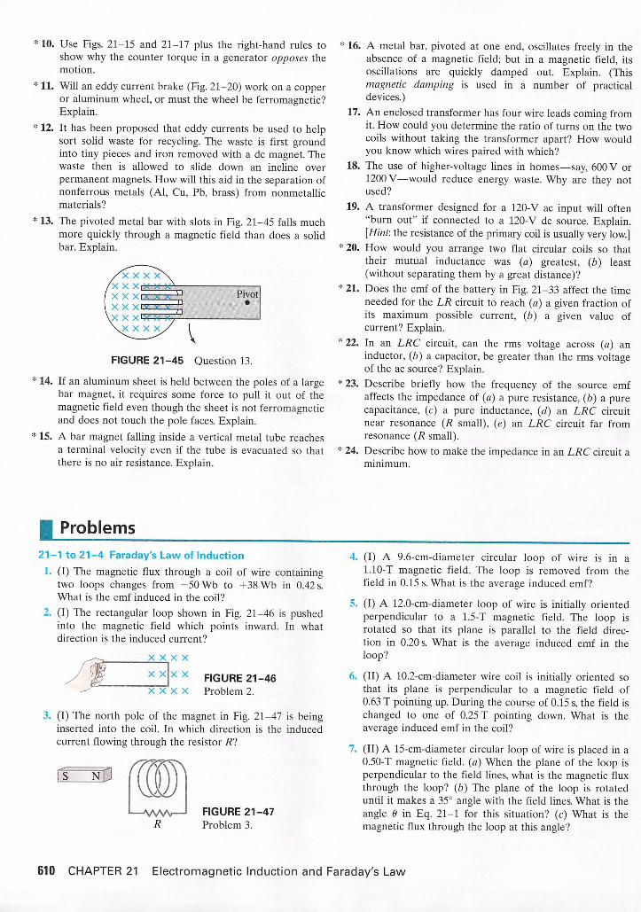
* 13. The pivoted metal bar with slots in Fig. 21-45 falls muchmore quickly through a magnetic field than does a solidbar. Explain.
FIGURE 21-45 Question 13.* 14. If an aluminum sheet is held between the poles of a large
bar magnet, it requires some force to pull it out of themagnetic field even though the sheet is not ferromagneticand does not touch the pole faces. Explain.
* 15. A bar magnet falling inside a vertical metal tube reachesa terminal velocity even if the tube is evacuated so thatthere is no air resistance. Explain.
* 16. A metal bar, pivoted at one end, oscillates freely in theabsence of a magnetic field; but in a magnetic field, itsoscillations are quickly damped out. Explain. (Thismagnetic damping is used in a number of practicaldevices.)
17. An enclosed transformer has four wire leads coming fromit. How could you determine the ratio of turns on the twocoils without taking the transformer apart? How wouldyou know which wires paired with which?
18. The use of higher-voltage lines in homes—say, 600 V or1200 V—would reduce energy waste. Why are they notused?
19. A transformer designed for a 120-V ac input will often"burn out" if connected to a 120-V dc source. Explain.[Hint: the resistance of the primary coil is usually very low.]
* 20. How would you arrange two flat circular coils so thattheir mutual inductance was (a) greatest, (b) least(without separating them by a great distance)?
* 21. Does the emf of the battery in Fig. 21-33 affect the timeneeded for the LR circuit to reach (a) a given fraction ofits maximum possible current, (b) a given value ofcurrent? Explain.
* 22. In an LRC circuit, can the rms voltage across (a) aninductor, (b) a capacitor, be greater than the rms voltageof the ac source? Explain.
* 23. Describe briefly how the frequency of the source emfaffects the impedance of (a) a pure resistance, (ft) a purecapacitance, (c) a pure inductance, (d) an LRC circuitnear resonance (R small), (e) an LRC circuit far fromresonance (R small).
* 24. Describe how to make the impedance in an LRC circuit aminimum.
| Problems21-1 to 21-4 Faraday's Law of Induction
1. (I) The magnetic flux through a coil of wire containingtwo loops changes from -50 Wb to +38 Wb in 0.42 s.What is the emf induced in the coil?
2. (I) The rectangular loop shown in Fig. 21-46 is pushedinto the magnetic field which points inward. In whatdirection is the induced current?
-<---, X X X X
j W X X X X FIGURE 21-46X X X X Problem 2.
3. (I) The north pole of the magnet in Fig. 21-47 is beinginserted into the coil. In which direction is the inducedcurrent flowing through the resistor R?
TDFIGURE 21-47Problem 3.
4. (I) A 9.6-cm-diameter circular loop of wire is in a1.10-T magnetic field. The loop is removed from thefield in 0.15 s. What is the average induced emf?
5. (I) A 12.0-cm-diameter loop of wire is initially orientedperpendicular to a 1.5-T magnetic field. The loop isrotated so that its plane is parallel to the field direction in 0.20 s. What is the average induced emf in theloop?
6. (II) A 10.2-cm-diameter wire coil is initially oriented sothat its plane is perpendicular to a magnetic field of0.63 T pointing up. During the course of 0.15 s, the field ischanged to one of 0.25 T pointing down. What is theaverage induced emf in the coil?
7. (II) A 15-cm-diameter circular loop of wire is placed in a0.50-T magnetic field, (a) When the plane of the loop isperpendicular to the field lines, what is the magnetic fluxthrough the loop? (b) The plane of the loop is rotateduntil it makes a 35° angle with the field lines. What is theangle 9 in Eq. 21-1 for this situation? (c) What is themagnetic flux through the loop at this angle?
610 CHAPTER 21 Electromagnetic Induction and Faraday's Law

8. (II) (a) If the resistance of the resistor in Fig. 21-48 isslowly increased, what is the direction of the currentinduced in the small circular loop inside the larger loop?(b) What would it be if the small loop were placed outsidethe larger one, to the left?
13.
WWv—WFIGURE 21-48Problem 8.
9. (II) What is the direction of the induced current in thecircular loop due to the current shown in each part ofFig. 21-49?
/ increasing
■ / decreasing
14.
15
(II) A circular loop in the plane of the paper lies in a0.75-T magnetic field pointing into the paper. If the loop'sdiameter changes from 20.0 cm to 6.0 cm in 0.50 s, (a) whatis the direction of the induced current, (b) what is themagnitude of the average induced emf, and (c) if the coilresistance is 2.5 ft, what is the average induced current?(II) The moving rod in Fig. 21-12 is 13.2 cm long andgenerates an emf of 120 mV while moving in a 0.90-Tmagnetic field, (a) What is its speed? (b) What is the electric field in the rod?(II) Part of a single rectangular loop of wire with dimensions shown in Fig. 21-51 is situated inside a region ofuniform magnetic field of 0.550 T The total resistance ofthe loop is 0.230 ft. Calculate the force required to pullthe loop from the field (to the right) at a constant velocityof 3.40 m/s. Neglect gravity.
(a) (b)
X X
X
X X X |
X X X x !
X X X X x !
X X
X
X X X ]
X X X x !
11.
12.
/ decreasing / constant
( c ) ( d )
FIGURE 21-49 Problem 9.
10. (II) If the solenoid in Fig. 21-50 is being pulled awayfrom the loop shown, in what direction is the inducedcurrent in the loop?
FIGURE 21-50 Problem 10.
(II) The magnetic field perpendicular to a circular wireloop 12.0 cm in diameter is changed from +0.52 T to-0.45 T in 180 ms, where + means the field points awayfrom an observer and - toward the observer, (a) Calculatethe induced emf. (b) In what direction does the inducedcurrent flow?(II) The moving rod in Fig. 21-12 is 12.0 cm long and ispulled at a speed of 15.0 cm/s. If the magnetic field is0.800 T, calculate (a) the emf developed, and (b) the electric field felt by electrons in the rod.
FIGURE 21-51 Problem 15.
16. (II) A 500-turn solenoid, 25 cm long, has a diameter of2.5 cm. A 10-turn coil is wound tightly around the centerof the solenoid. If the current in the solenoid increasesuniformly from 0 to 5.0 A in 0.60 s, what will be theinduced emf in the short coil during this time?
17. (II) In Fig. 21-12, the rod moves with a speed of 1.6 m/s,is 30.0 cm long, and has a resistance of 2.5 ft. Themagnetic field is 0.35 T, and the resistance of theU-shaped conductor is 25.0 ft at a given instant. Calculate(a) the induced emf, (b) the current in the U-shapedconductor, and (c) the external force needed to keep therod's velocity constant at that instant.
18. (Ill) A 22.0-cm-diameter coil consists of 20 turns of circularcopper wire 2.6 mm in diameter. A uniform magnetic field,perpendicular to the plane of the coil, changes at a rate of8.65 X IO"3 T/s. Determine (a) the current in the loop, and(b) the rate at which thermal energy is produced.
19. (Ill) The magnetic field perpendicular to a single 13.2-cm-diameter circular loop of copper wire decreases uniformlyfrom 0.750 T to zero. If the wire is 2.25 mm in diameter,how much charge moves past a point in the coil duringthis operation?
21-5 Generators20. (I) A simple generator is used to generate a peak output
voltage of 24.0 V The square armature consists of windings that are 6.0 cm on a side and rotates in a field of0.420 T at a rate of 60.0 rev/s. How many loops of wireshould be wound on the square armature?
Problems 611

21. (II) The generator of a car idling at 1100 rpm produces12.4 V What will the output be at a rotation speed of2500 rpm, assuming nothing else changes?
22. (II) Show that the rms output (Section 18-7) of an acgenerator is VTms = NABco/Vl, where co = 2trf.
23. (II) A simple generator has a 320-loop square coil 21.0 cmon a side. How fast must it turn in a 0.650-T field toproduce a 120-V peak output?
24. (II) A 450-loop circular armature coil with a diameter of8.0 cm rotates at 120 rev/s in a uniform magnetic field ofstrength 0.55 T. (a) What is the rms voltage output of thegenerator? (b) What would you do to the rotationfrequency in order to double the rms voltage output?
25. (II) A generator rotates at 85 Hz in a magnetic field of0.030 T. It has 1000 turns and produces an rms voltage of150 V and an rms current of 70.0 A. (a) What is the peakcurrent produced? (b) What is the area of each turn ofthe coil?
21-6 Back EMF andTorque* 26. (I) A motor has an armature resistance of 3.25 ft. If it
draws 8.20 A when running at full speed and connected toa 120-V line, how large is the back emf?
* 27. (I) The back emf in a motor is 72 V when operating at1800 rpm. What would be the back emf at 2500 rpm if themagnetic field is unchanged?
* 28. (II) The back emf in a motor is 95 V when the motor isoperating at 1000 rpm. How would you change themotor's magnetic field if you wanted to reduce the backemf to 65 V when the motor was running at 2500 rpm?
*29. (II) What will be the current in the motor ofExample 21-9 if the load causes it to run at half speed?
21-7 Transformers[Assume 100% efficiency, unless stated otherwise.]30. (I) A transformer is designed to change 120 V into
10,000 V, and there are 164 turns in the primary coil. Howmany turns are in the secondary coil?
31. (I) A transformer has 320 turns in the primary coil and120 in the secondary coil. What kind of transformer is this,and by what factor does it change the voltage? By whatfactor does it change the current?
32. (I) A step-up transformer increases 25 V to 120 V What isthe current in the secondary coil as compared to theprimary coil?
33. (I) Neon signs require 12 kV for their operation. To operatefrom a 240-V line, what must be the ratio of secondary toprimary turns of the transformer? What would the voltageoutput be if the transformer were connected backward?
34. (II) A model-train transformer plugs into 120-V ac anddraws 0.35 A while supplying 7.5 A to the train, (a) Whatvoltage is present across the tracks? (b) Is the transformer step-up or step-down?
35. (II) The output voltage of a 95-W transformer is 12 V, andthe input current is 22 A. (a) Is this a step-up or a step-downtransformer? (b) By what factor is the voltage multiplied?
36. (II) A transformer has 330 primary turns and 1340 secondaryturns. The input voltage is 120 V and the output current is15.0 A. What are the output voltage and input current?
37. (II) If 30 MW of power at 45 kV (rms) arrives at a townfrom a generator via 4.0-ft transmission lines, calculate(a) the emf at the generator end of the lines, and (b) thefraction of the power generated that is wasted in the lines.
38. (Ill) 65 kW is to arrive at a town over two 0.100-ft lines.Estimate how much power is saved if the voltage isstepped up from 120 V to 1200 V and then down again,rather than simply transmitting at 120 V Assume thetransformers are each 99% efficient.
*21-9 Inductance* 39. (I) If the current in a 180-mH coil changes steadily from
25.0 A to 10.0 A in 350 ms, what is the magnitude of theinduced emf?
* 40. (I) What is the inductance of a coil if the coil produces anemf of 2.50 V when the current in it changes from-28.0 mA to +31.0 mA in 12.0 ms?
*41. (I) What is the inductance L of a 0.60-m-long air-filledcoil 2.9 cm in diameter containing 10,000 loops?
* 42. (I) How many turns of wire would be required to make a130-mH inductance out of a 30.0-cm-long air-filled coilwith a diameter of 5.2 cm?
* 43. (II) An air-filled cylindrical inductor has 2800 turns, and itis 2.5 cm in diameter and 28.2 cm long, (a) What is itsinductance? (b) How many turns would you need togenerate the same inductance if the core were iron-filledinstead? Assume the magnetic permeability of iron isabout 1200 times that of free space.
* 44. (II) A coil has 2.25-ft resistance and 440-mH inductance.If the current is 3.00 A and is increasing at a rate of3.50 A/s, what is the potential difference across the coil atthis moment?
* 45. (Ill) A long thin solenoid of length / and cross-sectionalarea A contains 7Vj closely packed turns of wire. Wrappedtightly around it is an insulated coil of N2 turns, Fig. 21-52.Assume all the flux from coil 1 (the solenoid) passesthrough coil 2, and calculate the mutual inductance.
FIGURE 21-52 Problem 45.
* 46. (Ill) The wire of a tightly wound solenoid is unwound andused to make another tightly wound solenoid of twice thediameter. By what factor does the inductance change?
* 21-10 Magnetic Energy Storage* 47. (I) The magnetic field inside an air-filled solenoid 36 cm
long and 2.0 cm in diameter is 0.80 T. Approximately howmuch energy is stored in this field?
* 48. (II) At a given instant the current through an inductor is50.0 mA and is increasing at the rate of 115 mA/s. What isthe initial energy stored in the inductor if the inductanceis known to be 60.0 mH, and how long does it take for theenergy to increase by a factor of 10 from the initial value?
612 CHAPTER 21 Electromagnetic Induction and Faraday's Law

* 49. (II) Assuming the Earth's magnetic field averages about0.50 x IO"4 T near the surface of the Earth, estimate thetotal energy stored in this field in the first 10 km abovethe Earth's surface.
* 21-11 LR Circuit* 50. (II) Determine AI/At at t = 0 (when the battery is
connected) for the LR circuit of Fig. 21-33 and show thatif / continued to increase at this rate, it would reach itsmaximum value in one time constant.
*51. (Ill) After how many time constants does the current in' Fig. 21-33 reach within (a) 10%, (b) 1.0%, and (c) 0.1% of
its maximum value?* 52. (Ill) Two tightly wound solenoids have the same length
and circular cross-sectional area. But solenoid 1 uses wirethat is half as thick as solenoid 2. (a) What is the ratioof their inductances? (b) What is the ratio of their inductive time constants (assuming no other resistance in thecircuits)?
* 21-12 AC Circuits and Reactance
*53. (I) What is the reactance of a 7.20-/xF capacitor at afrequency of (a) 60.0 Hz, (b) 1.00 MHz?
*54. (I) At what frequency will a 22.0-mH inductor have areactance of 660 ft?
*55. (I) At what frequency will a 2.40-/xF capacitor have areactance of 6.70 kft?
*56. (II) Plot a graph of the reactance of a 1.0-uF capacitoras a function of frequency from 10 to 1000 Hz.
*57. (II) Plot a graph of the reactance of a 1.0-mH inductoras a function of frequency from 100 to 10,000 Hz.
* 58. (II) Calculate the reactance of, and rms current in, a160-mH radio coil connected to a 240-V (rms) 10.0-kHzac line. Ignore resistance.
* 59. (II) An inductance coil operates at 240 V and 60.0 Hz. Itdraws 12.8 A. What is the coil's inductance?
*60. (II) (a) What is the reactance of a well-insulated0.030-/xF capacitor connected to a 2.0-kV (rms) 720-Hz line?(b) What will be the peak value of the current?
21-13 LRC Circuits*61. (I) A 30-kft resistor is in series with a 45-mH inductor
and an ac source. Calculate the impedance of the circuit ifthe source frequency is (a) 50 Hz, and (b) 3.0 X 10⁴Hz.
*62. (I) A 3.5-kft resistor and a 4.0-yuF capacitor areconnected in series to an ac source. Calculate the impedance of the circuit if the source frequency is (a) 60 Hz,and (b) 60,000 Hz.
* 63. (I) For a 120-V rms 60-Hz voltage, an rms current of 70 mApassing through the human body for 1.0 s could be lethal.What must be the impedance of the body for this to occur?
* 64. (II) What is the resistance of a coil if its impedance is235 ft and its reactance is 135 ft?
* 65. (II) What are the total impedance, phase angle, and rmscurrent in an LRC circuit connected to a 10.0-kHz,725-V (rms) source if L = 22.0 mH, R = 8.70 kft, andC = 6250 pF?
* 66. (Ill) A 2.5-kft resistor in series with a 420-mH inductor isdriven by an ac power supply. At what frequency is theimpedance double that of the impedance at 60 Hz?
* 67. (HI) (a) What is the rms current in an RL circuit when a60.0-Hz 120-V rms ac voltage is applied, whereR = 1.80 kft, and L = 350 mH? (b) What is the phaseangle between voltage and current? (c) What are the rmsvoltage readings across R and L?
*68. (Ill) (a) What is the rms current in an RC circuit ifR = 8.80 kft, C = 1.80 pF, and the rms applied voltage is120 V at 60.0 Hz? (b) What is the phase angle betweenvoltage and current? (c) What are the voltmeter readingsacross R and C?
* 21-14 Resonance in AC Circuits* 69. (I) A 3500-pF capacitor is connected to a 55.0-uH coil of
resistance 3.00 ft. What is the resonant frequency of thiscircuit?
* 70. (I) The variable capacitor in the tuner of an AM radio has acapacitance of 2800 pF when the radio is tuned to a stationat 580 kHz. (a) What must be the capacitance for a station at1600 kHz? (b) What is the inductance (assumed constant)?
*71. (II) An LRC circuit has L = 14.8 mH and R = 4.40 ft.(a) What value must C have to produce resonance at3600 Hz? (b) What will be the maximum current at resonance if the peak external voltage is 150 V?
| General Problems72. Suppose you are looking at two current loops in the plane
of the page as shown in Fig. 21-53. When switch S isthrown in the left-hand coil, (a) what is the direction ofthe induced current in the other loop? (b) What is thesituation after a "long" time? (c) What is the direction ofthe induced current in the right-hand loop if that loopis quickly pulled horizontally to the right?o FIGURE 21-53
Problem 72.
73. A square loop 24.0 cm on a side has a resistance of5.20 ft. It is initially in a 0.665-T magnetic field, with itsplane perpendicular to B, but is removed from the field in40.0 ms. Calculate the electric energy dissipated in thisprocess.
74. A high-intensity desk lamp is rated at 45 W but requiresonly 12 V It contains a transformer that converts 120-Vhousehold voltage, (a) Is the transformer step-up orstep-down? (b) What is the current in the secondary coilwhen the lamp is on? (c) What is the current in theprimary coil? (d) What is the resistance of the bulbwhen on?
General Problems 613

75. Power is generated at 24 kV at a generating plant located118 km from a town that requires 50 MW of power at12 kV Two transmission lines from the plant to the towneach have a resistance of 0.10 ft/km. What should theoutput voltage of the transformer at the generating plantbe for an overall transmission efficiency of 98.5%,assuming a perfect transformer?
76. The primary windings of a transformer which has an 80%efficiency are connected to 110-V ac.The secondary windings are connected across a 2.4-ft, 75-W lightbulb.(a) Calculate the current through the primary windings ofthe transformer, (b) Calculate the ratio of the numberof primary windings of the transformer to the number ofsecondary windings of the transformer.
77. A pair of power transmission lines each have a 0.80-ftresistance and carry 740 A over 9.0 km. If the rms inputvoltage is 42 kV, calculate (a) the voltage at the other end,(b) the power input, (c) power loss in the lines, and(d) the power output.
78. Two resistanceless rails rest 32 cm apart on a 6.0° ramp.They are joined at the bottom by a 0.60-ft resistor. At thetop a copper bar of mass 0.040 kg (ignore its resistance) is laidacross the rails. The whole apparatus is immersed in avertical 0.55-T field. What is the terminal (steady) velocityof the bar as it slides frictionlessly down the rails?
79. Show that the power loss in transmission lines, PL. isgiven by PL = (PT)2 RJV2, where PT is the power transmitted to the user, V is the delivered voltage, and RL isthe resistance of the power lines.
80. A coil with 150 turns, a radius of 5.0 cm, and a resistanceof 12 ft surrounds a solenoid with 230 turns/cm and a radiusof 4.5 cm; see Fig. 21-54. The current in the solenoidchanges at a constant rate from 0 to 2.0 A in 0.10 s. Calculate the magnitude and direction of the induced current inthe coil.
FIGURE 21-54 Problem 80.
81. A certain electronic device needs to be protected againstsudden surges in current. In particular, after the power isturned on the current should rise no more than 7.5 mA inthe first 120 ps. The device has resistance 150 ft and isdesigned to operate at 55 mA. How would you protectthis device?
82. A 25-turn 12.5-cm-diameter coil is placed between thepole pieces of an electromagnet. When the magnet isturned on, the flux through the coil changes, inducing anemf. At what rate (in T/s) must the field produced by themagnet change if the emf is to be 120 V?
* 83. Calculate the peak output voltage of a simple generatorwhose square armature windings are 6.60 cm on a side;the armature contains 155 loops and rotates in a field of0.200 T at a rate of 120 rev/s.
*84. Typical large values for electric and magnetic fieldsattained in laboratories are about 1.0 X 10⁴V/m and2.0 T. (a) Determine the energy density for each field andcompare, (b) What magnitude electric field would beneeded to produce the same energy density as the 2.0-Tmagnetic field?
* 85. What is the inductance L of the primary of a transformerwhose input is 220 V at 60.0 Hz if the current drawn is5.8 A? Assume no current in the secondary.
* 86. A 130-mH coil whose resistance is 18.5 ft is connected toa capacitor C and a 1360-Hz source voltage. If the currentand voltage are to be in phase, what value must C have?
* 87. An inductance coil draws 2.5-A dc when connected to a36-V battery. When connected to a 60-Hz 120-V (rms)source, the current drawn is 3.8 A (rms). Determine theinductance and resistance of the coil.A 135-mH inductor with 2.0-ft resistance is connected inseries to a 20-p.F capacitor and a 60-Hz, 45-V source.Calculate (a) the rms current, and (b) the phase angle.The Q factor of a resonance circuit can be defined asthe ratio of the voltage across the capacitor (or inductor)to the voltage across the resistor, at resonance. The largerthe Q factor, the sharper the resonance curve will beand the sharper the tuning, (a) Show that the Q factor isgiven by the equation Q = (1/R)Vl/C. (b) At a resonant frequency fQ = 1.0 MHz, what must be the valuesof L and R to produce a Q factor of 550? Assume thatC = 0.010 p¥.
*88.
89.
Answers to ExercisesA: 0.0102 Wb.B: (a) Counterclockwise; (b) clockwise; (c) zero;
(d) counterclockwise.
C: Counterclockwise.D: 10 turns.
614 CHAPTER 21 Electromagnetic Induction and Faraday's Law