resource control in network elements · technical report number 534 computer laboratory...
TRANSCRIPT

Technical ReportNumber 534
Computer Laboratory
UCAM-CL-TR-534ISSN 1476-2986
Resource control in network elements
Austin Donnelly
April 2002
JJ Thomson Avenue
Cambridge CB3 0FD
United Kingdom
phone +44 1223 763500
http://www.cl.cam.ac.uk/

c© 2002 Austin Donnelly
This technical report is based on a dissertation submitted January2002 by the author for the degree of Doctor of Philosophy to theUniversity of Cambridge, Pembroke College.
Technical reports published by the University of CambridgeComputer Laboratory are freely available via the Internet:
http://www.cl.cam.ac.uk/TechReports/
Series editor: Markus Kuhn
ISSN 1476-2986

Acknowledgements
I would like to thank my supervisor for starting me on this long and varied jour-
ney, and to Ian Leslie, Jonathan Smith and Steve Hand whose encouragement
and practical advice enabled me to complete it.
Research into operating systems does not happen in a vacuum; I am indebted
to the members of the Systems Reseach Group for providing a stimulating en-
vironment, both at work and afterwards. Discussions with Tim Harris, Richard
Mortier, and Dave Stewart were entertaining and useful. I would like to con-
gratulate Martyn Johnson on running a consistent and reliable computing envi-
ronment, despite my best attempts at flooding his network.
I appreciate the time taken by James Bulpin, Jon Crowcroft, Tim Deegan, Keir
Fraser, Tim Harris, and Richard Mortier in proof-reading drafts of this disser-
tation. Any remaining mistakes are entirely my own.
I spent the summer of 1999 at AT&T Florham Park during which time I discov-
ered about working in a commercial research setting. I’d like to thank Kobus
van der Merwe, Cormac Sreenan, and Chuck Kalmanek for making my time at
Florham Park productive and enjoyable.
The first three years of this work were funded by ESPRIT Long-Term Research
project 21917 (Pegasus II); I am eternally grateful to my parents for their sup-
port after this, both financial and familial.
Finally, I’d like to thank my friends from the various outdoor activity clubs
– their welcome weekend distractions ensured I returned on Mondays with a
fresh outlook.
3

“All we know is the phenomenon: we spend our time sending
messages to each other, talking and trying to listen at the same
time, exchanging information. This seems to be our most urgent
biological function; it is what we do with our lives.”
— Lewis Thomas, “The Lives of a Cell”
4
Contents
1 Introduction 8
1.1 Data processing in the network . . . . . . . . . . . . . . . . . 8
1.2 Network Element Operating Systems . . . . . . . . . . . . . . 11
1.3 Dissertation outline . . . . . . . . . . . . . . . . . . . . . . . 14
2 Background 16
2.1 The path concept . . . . . . . . . . . . . . . . . . . . . . . . 18
2.1.1 The x-Kernel . . . . . . . . . . . . . . . . . . . . . . 18
2.1.2 Scout v2 . . . . . . . . . . . . . . . . . . . . . . . . 19
2.1.3 Escort . . . . . . . . . . . . . . . . . . . . . . . . . . 27
2.1.4 Resource containers . . . . . . . . . . . . . . . . . . 32
2.1.5 Cohort scheduling . . . . . . . . . . . . . . . . . . . 34
2.2 Other path-like I/O abstractions . . . . . . . . . . . . . . . . . 35
2.2.1 Refcounted copy semantics: Fbufs, IO-Lite . . . . . . 35
2.2.2 Move semantics: Roadrunner, container shipping . . . 36
2.2.3 Upcalls . . . . . . . . . . . . . . . . . . . . . . . . . 37
2.2.4 Path-based component frameworks . . . . . . . . . . 38
2.3 Protection and IPC . . . . . . . . . . . . . . . . . . . . . . . 38
2.3.1 Lightweight IPC . . . . . . . . . . . . . . . . . . . . 39
2.3.2 Capability-based IPC . . . . . . . . . . . . . . . . . . 40
2.3.3 IPC by thread tunnelling . . . . . . . . . . . . . . . . 42
2.3.4 Discussion . . . . . . . . . . . . . . . . . . . . . . . 43
2.4 Protection models . . . . . . . . . . . . . . . . . . . . . . . . 44
2.4.1 Kernel-based systems . . . . . . . . . . . . . . . . . . 44
2.4.2 Protected shared libraries . . . . . . . . . . . . . . . . 45
2.4.3 Safe kernel extensions . . . . . . . . . . . . . . . . . 46
2.5 Vertically structured OSes . . . . . . . . . . . . . . . . . . . 47
2.5.1 Nemesis . . . . . . . . . . . . . . . . . . . . . . . . . 47
2.5.2 Exokernels . . . . . . . . . . . . . . . . . . . . . . . 52
2.6 Active networks . . . . . . . . . . . . . . . . . . . . . . . . . 53
5

2.7 Smart devices . . . . . . . . . . . . . . . . . . . . . . . . . . 55
2.8 Summary . . . . . . . . . . . . . . . . . . . . . . . . . . . . 57
3 Nemesis 58
3.1 NTSC . . . . . . . . . . . . . . . . . . . . . . . . . . . . . . 58
3.1.1 Interrupts . . . . . . . . . . . . . . . . . . . . . . . . 59
3.1.2 API . . . . . . . . . . . . . . . . . . . . . . . . . . . 60
3.2 Scheduler activations . . . . . . . . . . . . . . . . . . . . . . 61
3.3 Protection, scheduling and activation domains . . . . . . . . . 61
3.4 Same-machine communication . . . . . . . . . . . . . . . . . 62
3.4.1 IDC . . . . . . . . . . . . . . . . . . . . . . . . . . . 62
3.4.2 CALLPRIV sections . . . . . . . . . . . . . . . . . . 63
3.4.3 I/O channels . . . . . . . . . . . . . . . . . . . . . . 63
3.5 Network stack . . . . . . . . . . . . . . . . . . . . . . . . . . 65
3.5.1 Receive processing . . . . . . . . . . . . . . . . . . . 65
3.5.2 Transmit processing . . . . . . . . . . . . . . . . . . 67
3.5.3 Control plane . . . . . . . . . . . . . . . . . . . . . . 68
3.6 Summary . . . . . . . . . . . . . . . . . . . . . . . . . . . . 68
4 Network device driver model 69
4.1 Receive processing . . . . . . . . . . . . . . . . . . . . . . . 70
4.1.1 Demultiplexing data . . . . . . . . . . . . . . . . . . 74
4.2 Kernel-to-user packet transport . . . . . . . . . . . . . . . . . 78
4.3 Transmit processing . . . . . . . . . . . . . . . . . . . . . . . 79
4.3.1 Efficient explicit wake-ups . . . . . . . . . . . . . . . 80
4.3.2 User-to-kernel packet transport . . . . . . . . . . . . . 84
4.3.3 Transmit scheduling . . . . . . . . . . . . . . . . . . 88
4.4 Results . . . . . . . . . . . . . . . . . . . . . . . . . . . . . . 91
4.4.1 Traditional performance metrics . . . . . . . . . . . . 94
4.4.2 QoS metrics . . . . . . . . . . . . . . . . . . . . . . . 100
4.5 Summary . . . . . . . . . . . . . . . . . . . . . . . . . . . . 105
5 Paths 107
5.1 The case for tunnelling in a vertically structured OS . . . . . . 107
5.2 Code, protection and schedulable entities . . . . . . . . . . . 110
5.2.1 Modules . . . . . . . . . . . . . . . . . . . . . . . . 110
5.2.2 Tasks . . . . . . . . . . . . . . . . . . . . . . . . . . 111
5.2.3 Paths . . . . . . . . . . . . . . . . . . . . . . . . . . 112
5.2.4 Protected modules . . . . . . . . . . . . . . . . . . . 113
5.2.5 CALLPRIVs . . . . . . . . . . . . . . . . . . . . . . . 114
6

5.3 Expert pod implementation . . . . . . . . . . . . . . . . . . . 114
5.3.1 Bootstrapping . . . . . . . . . . . . . . . . . . . . . . 115
5.3.2 Calling a pod . . . . . . . . . . . . . . . . . . . . . . 118
5.3.3 Pod environment . . . . . . . . . . . . . . . . . . . . 122
5.3.4 Pod I/O channels . . . . . . . . . . . . . . . . . . . . 128
5.4 Results . . . . . . . . . . . . . . . . . . . . . . . . . . . . . . 132
5.4.1 Micro-benchmarks . . . . . . . . . . . . . . . . . . . 132
5.4.2 Pod I/O performance . . . . . . . . . . . . . . . . . . 134
5.5 Summary . . . . . . . . . . . . . . . . . . . . . . . . . . . . 136
6 System evaluation 138
6.1 Motivation . . . . . . . . . . . . . . . . . . . . . . . . . . . . 138
6.1.1 Requirements . . . . . . . . . . . . . . . . . . . . . . 140
6.2 Architecture and implementation . . . . . . . . . . . . . . . . 141
6.2.1 Caches . . . . . . . . . . . . . . . . . . . . . . . . . 143
6.2.2 Buffer allocation and usage . . . . . . . . . . . . . . 144
6.2.3 Alternative architectures . . . . . . . . . . . . . . . . 145
6.3 Results . . . . . . . . . . . . . . . . . . . . . . . . . . . . . . 147
6.3.1 Cost of protection . . . . . . . . . . . . . . . . . . . . 148
6.3.2 Benefits of isolation . . . . . . . . . . . . . . . . . . 150
6.4 Summary . . . . . . . . . . . . . . . . . . . . . . . . . . . . 152
7 Conclusion 153
7.1 Summary . . . . . . . . . . . . . . . . . . . . . . . . . . . . 153
7.2 Contributions . . . . . . . . . . . . . . . . . . . . . . . . . . 156
7.3 Integration with mainstream OSes . . . . . . . . . . . . . . . 157
7.3.1 Network driver scheme . . . . . . . . . . . . . . . . . 158
7.3.2 Pods on Linux . . . . . . . . . . . . . . . . . . . . . 158
7.3.3 Paths on Linux . . . . . . . . . . . . . . . . . . . . . 159
7.4 Future work . . . . . . . . . . . . . . . . . . . . . . . . . . . 159
A Interfaces 161
A.1 Pod.if . . . . . . . . . . . . . . . . . . . . . . . . . . . . . 161
A.2 PodBinder.if . . . . . . . . . . . . . . . . . . . . . . . . 163
References 165
7

Chapter 1
Introduction
As processing on the data path moves into the network, the problem emerges
of how best to allocate and schedule scarce resources within routers. This
dissertation describes why this is a problem, how current work fails to address
this problem, and presents its solution in the form of Expert; a new NEOS
(Network Element Operating System) which supports accurate accounting and
scheduling of all resources.
1.1 Data processing in the network
The Internet is a hierarchy of interconnected networks. As distance from the
high-speed core increases, link speeds drop, aggregation decreases and the
amount of router memory and processing power available per byte increases.
In the core, traffic is switched entirely in hardware in order to cope with the vast
data rate. However, the static nature of this hardware acceleration loses flexibil-
ity: the ability to meet unplanned, evolving requirements has been exchanged
for performance gains. For a core offering only basic connectivity, this is not
a serious problem. In contrast, towards the edge of the network programmable
software-based routers become feasible, allowing considerable intelligence in
routing decisions [Pradhan99, Peterson99].
Furthermore, there are sufficient resources available near the edge today to al-
low these programmable routers to manipulate data in the packets [Amir98].
Useful data processing includes media transcoding, for example to allow het-
erogeneous receivers to participate in a high-bandwidth flow by down-sampling
8

the media to an appropriate rate [Fox96]. Other potential manipulations in-
clude information distillation or filtering, for example to aggregate sensor data,
or generate a “thumbnails” video channel based on scaling down several other
channels.
Other uses of in-network data processing are transparent to the endpoints in-
volved. For example, protocol boosters [Feldmeier98] perform extra process-
ing in portions of the network to improve performance in some manner, e.g. by
ACK spacing, or maintaining a segment cache to shorten retransmit times on a
lossy network.
The need to process packet data is not limited to experimental or research sys-
tems; currently deployed network applications do so too. For example, some
protocols (e.g. FTP [Postel85], RTSP [Schulzrinne98], and H.323 [H323]) em-
bed endpoint information in the packet payload. Network elements that read
or rewrite this endpoint information (such as firewalls or NAT (Network Ad-
dress Translation) gateways [Egevang94]) thus need access not only to packet
headers, but also to packet bodies.
Another example of data processing on packet payloads arises in VPN (Virtual
Private Network) endpoints [Gleeson00]. A VPN ingress router aggregates
packets from multiple sources and encapsulates them for transmission through
a tunnel. At the far end of the tunnel, an egress router decapsulates and routes
the packets on to their next hop. Both of these VPN endpoint operations require
the packet payload to be processed (e.g. for checksum purposes), and in the
case of a secure VPN either encrypted or decrypted, both of which can be
CPU-intensive processing.
As these and other resource-intensive network-hosted functions are merged to
run on a single router, competition for scarce resources arises. The pressure
to integrate multiple functions into a single router comes from a variety of
directions:
• Separate network elements are more costly, partly due to the increased
amount of redundant equipment purchased, but also in terms of precious
rack-space.
• Having multiple network elements composed together may also compli-
cate the network architecture, especially if it needs to be transparent to
network users or an ISP (Internet Service Provider).
• A composition of network elements also makes dimensioning harder,
9

since a single under-powered element can cause the whole chain to under-
perform.
A programmable router integrating multiple functions requires resource alloca-
tion problems to be addressed in one location by flexible software scheduling.
If no scheduling is performed then the system’s performance is not predictable
during overload conditions. Proper resource management also enables admin-
istrative control over how system resources are allocated to various applications
or flows. For example, this allows latency-sensitive ASP (Application Service
Provider) or VoIP (Voice over IP) flows to be isolated from the effects of best-
effort flows such as email or web traffic. This need to schedule computation
on routers is gradually being recognised by others (e.g. [Qie01]), however the
majority of current systems lack proper resource control.
There are two main reasons why this is the case. The first is that when the
primary resource being consumed is outgoing link bandwidth, scheduling just
this implicitly controls the consumption of other resources. However, sophisti-
cated per-packet processing now consumes multiple resources. This mandates
a holistic approach to managing system resources such as network bandwidth,
the CPU, memory, and disk.
The second reason that resource control is not currently provided is that over-
provisioning is seen as a viable alternative. Over-provisioning is an insufficient
replacement for resource management for several reasons. Peak loads can be
between a hundred and a thousand times larger than average loads [Schwarz00]
necessitating larger, more expensive, configurations which are only fully used
during short peak periods. Also, for the largest systems, the average load will
be approaching the maximum possible capacity of the system, so there is sim-
ply no way to over-provision. Finally, the hardware in use tends to lag behind
the cutting edge, due to the expense and disruption involved in commissioning
new equipment.
This dissertation has argued for a flexible NEOS which can support new ap-
plications as they emerge, while giving QoS (Quality of Service) guarantees
to the processing of data flows in order to the remain in control of resource
consumption when under overload conditions. The next section claims that
current OSes are unsuitable platforms for resource-intensive network-hosted
applications, and gives reasons why this is the case.
10

1.2 Network Element Operating Systems
A NEOS is different from a workstation or server OS because it is transparent
to all but its administrators. For example, in a client OS, users are explicitly
authenticated. Server OSes run services on behalf of some local user, and the
services typically do their own application-level user authentication. However,
in a NEOS users are not explicitly authenticated. This is why resource control
on a network element is a challenge, because it is difficult to track resource
usage when the consumer has to be inferred from flow information combined
with administrative policy. Some protocols (for example IPSec) allow flows to
be tracked explicitly, making this problem somewhat easier.
This section now considers several existing NEOSes and argues that they are
inadequate because either they are inflexible, or they do not have sufficiently
detailed resource accounting.
Commercial embedded OSes are used by many network equipment vendors
in their products. For example, 3Com uses a mixture of VxWorks, QNX and
ThreadX [VxWorks99, Hildebrand92, ThreadX] along with other privately de-
veloped embedded OSes [Nessett00]. Cisco uses similar systems [QNX98],
alongside their own proprietary system known as IOS.
None of these products are designed with flexibility in mind; these closed sys-
tems do not allow administrator-supplied code to be run on them. They use
hard real-time OSes, requiring the job mix to be known in advance to allow a
one-off static resource partitioning to be made at design time.
We do not consider this kind of system any further, since they cannot be classed
as programmable routers either in name or in function.
Both Unix and Windows NT can be used to route traffic, and are general enough
platforms to enable data to be processed by locally-supplied code. Windows
2000 has support for scheduling network I/O, as do many of the modern Unices,
for example Linux with CBQ (Class-Based Queueing). However, their model
assumes that the only resource used by network flows is bandwidth; they do
not schedule other resources used in processing packets in the kernel.
In the case of a split kernel / user-space implementation, the amount of time
spent in the kernel is hard (if not impossible) to schedule, resulting in live-
lock [Mogul96, Druschel96] unless steps are taken to ensure new packets are
not accepted until they can be properly accommodated. For example, clocked
11

interrupts [Smith93] can be used to reduce interrupt processing overheads.
The fundamental problem with these kinds of operating systems is that they are
built on a task-based scheduling paradigm which is ill-suited to recording the
resources used in processing flows of packets.
There are four reasons why task-based scheduling is inappropriate for process-
ing flows of packets:
1. When a single data flow is processed by multiple cooperating tasks, each
with their own resource allocations, it is hard to understand the required
allocation levels needed to achieve a balanced system, i.e. one in which
each task has a sufficient resource allocation, and no more.
2. There is a performance penalty due to the overheads of context switching
between tasks on a per-packet basis. These may be amortised by batching
multiple packets together before context switching, and this can happen
at any level in a system from interrupt mitigation schemes implemented
in devices to application-specified buffer flush trigger levels. However
any scheme which batches packets for common processing will by def-
inition increase their latency. There is a fundamental trade-off between
batch granularity and context switch overheads.
3. Multiple tasks co-operating to process a flow complicates resource recla-
mation since resources are owned by tasks, not flows. If the resources
associated with a flow need to be retracted, all the tasks involved need
to participate in the revocation. Depending on the system, atomic re-
source release may be impossible. As an example, Unix provides the
mechanism of process groups to allow multiple processes (e.g. a shell-
constructed pipeline) to be sent a signal atomically. However, killing
entire processes is a fairly coarse-grained approach to resource reclama-
tion, and more importantly, does not work if the processes were handling
multiple flows and the intention was to terminate just one flow.
4. When multiple tasks co-operate to process multiple flows, there are two
additional problems. Firstly, each task needs to perform a demultiplex
operation to recover the flow state. This is not too severe in the case
where there are few flows to distinguish between, but becomes time-
consuming when many flows are active. The standardisation of POSIX.1b
asynchronous I/O (which allows a callback function to be invoked when
data arrives) is an implicit acknowledgement of this problem. Secondly,
12

netrx
demuxnettx
other path
other path
Eth IP UDP MPEG UDP IP Eth
Figure 1.1: An example path through a networking stack and an MPEG
code module.
if flows are to be differentiated within a task, the task needs to sub-
schedule any processing it does. However, this aggravates the first prob-
lem by greatly increasing the number of scheduler settings needing to be
decided for the system as a whole.
In the case of a Unix-like system, it is tempting to argue that if there is only
one user-space process on the data path, then only one task is involved and
thus many of the problems listed above become moot. This is not so, since the
kernel itself must be considered a task: context switches occur between it and
user processes.
In fact, in most Unices this situation is exacerbated, since the kernel is sched-
uled implicitly on interrupts. [Black95] argues that if any significant processing
is performed in the kernel, then this is automatically work which is not sched-
uled according to administrative policy but rather scheduled by external (in
this case, network) events. This implies an undesirable loss of control over the
system’s resource usage.
These problems with task-based systems can be addressed by the introduc-
tion of the notion of a path as a first-class schedulable entity. The Scout
OS [Mosberger96, Mosberger97] is an example of a system designed around
such data communication paths.
Paths map closely onto the human view of the processing performed on a
packet as it traverses OS and application code; an example path is shown in Fig-
ure 1.1. The motivations the Scout authors give for paths are the increased per-
formance of embedded Internet appliances available through ILP (Integrated
Layer Processing), code specialisation, and early discard of work under over-
load conditions. The path is also the entity to which the use of resources is
charged. A side-effect of this work on performance tuning is the improved
QoS isolation, although the authors do not cite this as a major motivation for
13

them.
However, Scout is a static system which is configured and type-checked at
build-time: it does not support the dynamic loading of new code modules.
Its typesystem is fixed, and new types cannot be added at run-time. This is
unsurprising, given its original niche as an OS for Internet appliances.
Despite these problems with Scout, the concept of using paths as schedula-
ble entities is sound: per-path resource control directly simplifies the resource
allocation problem by providing one parameter per resource that governs all
processing applied to a particular flow of packets.
However, not all processing performed on a programmable router can be mean-
ingfully captured using only paths. For batch computation which proceeds
without significant interaction with other system components or is unrelated to
any particular traffic stream, the resource consumption is best represented and
controlled by a task abstraction.
Examples of such workloads includes system management tasks such as the
gathering and processing of statistics (e.g. for admission control), background
routing table optimisation [Draves99], or background management of cached
data (e.g. expiry, preemptive refresh, compression, index generation).
Having both paths and tasks allows each abstraction to be used where most ap-
propriate. A task-based system (e.g. Unix) without paths is not well suited to
accounting and scheduling different data streams. In contrast, a path-based sys-
tem (such as Scout) is optimised for processing high performance data streams,
but cannot account resources consumed on behalf of system housekeeping
tasks correctly.
It is the thesis of this dissertation that in an environment where a mix of data-
driven processing occurs alongside batch processing, both path and task ab-
stractions need to be provided by the underlying operating system in order to
prevent quality of service crosstalk between the competing workloads.
1.3 Dissertation outline
The balance of this dissertation is composed as follows. Chapter 2 covers re-
lated work and further motivates this dissertation by describing why previous
approaches are insufficient. Since Expert is substantially based on Nemesis,
14

Chapter 3 provides a brief summary for readers unfamiliar with it. The Expert
architecture and its prototype implementation are described in Chapters 4 and
5: Chapter 4 covers the network device driver model, while Chapter 5 describes
paths in Expert. Chapter 6 presents a large-scale example application showing
how Expert’s unique features can be used to differentiate the processing per-
formed on flows of data. Finally, Chapter 7 describes how the techniques de-
veloped for Expert might be implemented on other operating systems, suggests
areas for further work, and concludes this dissertation.
15

Chapter 2
Background
Today most enterprise-class routers offer some form of traffic shaping, which
their manufacturers are all too keen to pass off as a QoS-control architecture.
Cisco’s GSR12000 [McKeown95] is a typical example of such a router, of-
fering weighted fair queueing on outbound links. This is a reasonable way of
controlling the use of scarce link bandwidth, however the implicit assumption
is that most traffic is never subjected to much processing.
While this may be true of today’s protocols, open programmable routers offer
the potential to deploy new network-hosted functions that perform much more
computation on each packet, needing proper resource control for all resources
consumed. The IETF have recognised the existence of this niche, and termed
them middle boxes [Carpenter01], however they have not addressed resource
control concerns as yet.
Due to rapid changes in requirements, most middle boxes will be initially im-
plemented as modifications to existing software routers, even if they are subse-
quently turned into hardware.
There are a number of extant QoS-aware software routers, however they tend
to share the hardware vendors’ pre-occupation with scheduling bandwidth and
hoping other resources (mainly CPU) are adequately provisioned.
For example, the Pronto router [Hjalmtysson00] concentrates on separating
service-specific logic from the forwarding fast path. This allows the coupling
between the service logic and the data path to be varied, giving a range of per-
formance trade-offs. Using service logic to perform connection admission con-
trol is an example of a lightweight service entirely on the control plane. Service
16

logic which needs to peek frames occasionally or needs to sample all frames
but in an asynchronous manner is an example of a more resource-intensive ap-
plication. Finally, the most heavyweight variety of service logic supported by
Pronto makes service decisions inline on a per-packet basis; this corresponds
closely to the classic Active Network model described in [Tennenhouse96].
Unfortunately, the decision to implement Pronto as a minimal set of hooks
within the Linux kernel, while understandable, leads to the usual problems as-
sociated with resource control under Unix.
The Click modular router [Kohler00] is a more ambitious extension to the
Linux networking stack.1 It provides a convenient way of plugging code mod-
ules together to form a data-processing pipeline, type-checking the intercon-
nections to ensure they are sensible. Click does not provide an integrated re-
source scheduling framework: it allows traffic shaping, but it cannot identify
and schedule flows differently since its scheduling parameters are per-class, not
per flow. Click uses a non-preemptive scheduler, with packet queue modules
to force yields.
Click concentrates on the flow of data along paths between various modules.
This data-driven path-centric focus is not unique to Click: it is a recurring
idiom with some history.
This chapter begins by discussing other systems which use path-like abstrac-
tions to perform I/O. The use of IPC systems to perform I/O is considered next,
and previous work on IPC by thread tunnelling is described. Vertically struc-
tured OSes are presented as a means of avoiding IPC by allowing applications
to perform most of their own processing, but problems with their device han-
dling are outlined.
This chapter continues by describing active networks – they form a class of
applications which may benefit from being implemented over an OS offer-
ing quality of service guarantees to paths processing network flows. Finally,
this chapter discusses the conflicting pressures operating on device complex-
ity: some factors result in smarter devices, some result in dumber devices.
1It has since been ported to run natively over the University of Utah’s Flux OSKit, however,
the arguments presented here are still relevant.
17

Key:
message
protocol
sessionEth
IP
TCPUDP
Figure 2.1: Protocol demux traces a path through session objects in the
x-Kernel.
2.1 The path concept
The idea of an execution path through code induced by a flow of packets with
certain properties common among them is not particularly new. This section
summarises the innovations in this field and traces the concepts back to their
sources.
2.1.1 The x-Kernel
The x-Kernel [Hutchinson91] is a flexible architecture to aid protocol im-
plementation. Its modular design provides facilities for hierarchical protocol
composition, reference counted buffer management, hash tables, timeouts, and
threads within multiple address spaces. The x-Kernel defines three sorts of ob-
ject: protocol, session, and message. Protocol objects hold global state about
a particular network protocol (e.g. which ports are in use), and are similar to
classes in an object-oriented language. Session objects hold per-flow state, and
can be viewed as the instantiation of protocol objects. Message objects are
the active entities in the system; they are moved through sessions by shepherd
threads.
When a packet arrives, a shepherd thread is dispatched from a pool in the kernel
to handle the network interrupt. It calls the demultiplex operation on each
protocol in turn, discovering which session object is associated with this packet
(or creating a new one if there is no current association). The demultiplex
18

operation also selects the next protocol object to process the message with,
thus tracing a path through session objects and their associated protocol objects
as shown in Figure 2.1. If the next protocol object resides in user-space then
the shepherd thread switches to user mode and upcalls the application-supplied
protocol code. No pass is made through the CPU scheduler.
Packets are transmitted by an application pushing its payload into a previously
established session object. The session object encapsulates the payload ac-
cording to the protocol it is an instantiation of, and pushes the message down
towards the root of the protocol tree where the network device finally transmits
the frame. The user-space process issues a system call when it needs to cross
the user-kernel boundary on its way down towards the network device.
The motivation behind the x-Kernel was to allow layered protocol implemen-
tations to get the usual advantages of layered systems (e.g. maintainability and
flexibility) without the commonly perceived performance penalties described
in [Wakeman92]. The x-Kernel’s use of one thread per message was certainly
better than the alternative prevalent at the time: one thread per layer, with
queueing between each layer leading to high thread synchronisation overheads
and large queueing delays. Another problem with thread-per-layer schemes is
that bottlenecks are easily created: a single layer run by a thread with an insuf-
ficient guarantee limits the performance of all data flows through that layer.
However, thread-per-message also has its own problems. Without suitable in-
terlocking, threads can overtake each other leading to out-of-order message
delivery to the application. Care also needs to be taken to limit how many
shepherd threads are allocated to each connection, such that no connection is
starved due to other (overactive) connections. The x-Kernel uses a global pool
of shepherd threads, and so is vulnerable to this.
2.1.2 Scout v2
The Scout OS [Mosberger96, Mosberger97] was inspired by the x-Kernel, and
thus shares many of its features. The first public release of Scout was actually
the second internal version to be developed, hence it is known as “Scout v2”.
This section first describes Scout’s architecture in some detail, then considers
how it differs from the x-Kernel, and finally comments on Scout’s key features
and their suitability for providing QoS isolation between traffic flows.
19

Architecture
Scout introduced the path as a core OS abstraction. A path encapsulates the
processing which happens to a flow of packets, and provides fast access to per-
flow state. Scout’s model of a path arose as the unifying concept tying together
multiple optimisations such as ILP, fbufs (Section 2.2.1), and per-connection
code specialisation [Massalin92].
Scout code modules are (confusingly) called routers. Routers are analogous to
x-Kernel protocol objects, and are organised at system configuration time into
a graph showing possible interactions between routers. Scout routers demulti-
plex incoming packets to stages, the corresponding entity to x-Kernel sessions.
A path is defined to be the sequence of stages used to process packets in a flow.
A path also includes four queues (two at each end of the path, one for outgoing
and one for incoming data), and any per-flow state required by the code the
path traverses.
Paths are created based on a set of attributes (or invariants) which are true for
all packets in a flow. Typically this will be the participants’ IP addresses, port
numbers and protocol types but in theory any other data could be used to select
the packets to be handled by the new path. The attributes are placed in a hash
table which the path creator then passes to the initial router on the path. This
router creates a stage for the path, and selects the next router needed based on
the path’s attributes. The next router is then invoked to extend the path with its
corresponding stage; this extension procedure continues in a recursive fashion
until one of two situations occur. Firstly, the attributes may not be sufficient to
determine the next router, in which case a per-packet decision will be needed on
the data path at that stage. An example of this occurs in the IP-level router, in
order to select the appropriate interface to transmit a packet. The second reason
the path extension procedure may stop is because the router has no successor
(e.g. it is an application, or an Ethernet driver).
Once all the stages are linked together to form the path their establish()
functions are called, giving them the chance to perform any path-global optimi-
sations or initialisations. The path is now live and will begin receiving packets,
assuming that it grew all the way to a device driver.
When a frame arrives at a network device driver it calls the demux() operation
on the router connected to it, as specified at system configuration time. The
demux() function recursively calls the routers above it to determine which
20

recursivedemux
no path
pathfound
is pathdying ?
yes
no FIFO spaceavailable ?
no
yes assignshepherdthread
enqueueframe
framearrival
discard discard discard
Figure 2.2: Receive processing in Scout.
path the frame is for. Finally, a few other criteria are tested (see Figure 2.2)
before the frame is accepted.
Later, the system scheduler will select a thread from the receiving path’s thread
pool and activate it at the path’s entry point. This typically dequeues the first
message from the path’s input queue and calls the first stage’s deliver()
function. Processing of the message then continues from stage to stage until
the message reaches the end of the path, where is it added to the path’s output
queue. Scout uses a non-preemptive thread scheduler by default, so the thread
runs the entire path to completion (assuming there are no explicit yield points
in the code).
User applications are written to behave like routers. They can transmit pack-
ets by creating a path with appropriate attributes. Once the path is created,
deliver()-ing a packet to its user end results in the packet being encapsu-
lated and eventually queued for transmission by a device driver.
Comparison with x-Kernel
At first glance, the differences between Scout and the x-Kernel may seem cos-
metic, but there are some crucial changes:
Paths. Scout paths centralise state for all code layers involved in processing
packets from one flow, whereas the x-Kernel keeps this state distributed
with each layer, requiring flow state to be looked up at each layer for
every packet. This is despite [Tennenhouse89] giving clear reasons why
this kind of layered demultiplexing scheme gives rise to QoS crosstalk.
VM system. Because Scout is aimed at embedded Internet-connected systems,
21

driver
system runtime
irq / exn
Eth
IP
UDP
MPEG Key:
supervisor modeprotection domain
address space
code module
extent of threadexecution
Figure 2.3: Structure of Scout.
it uses a simple, single address space with no memory protection as
shown in Figure 2.3. This is in contrast to x-Kernel’s Unix-like protected
multiple address spaces.
Specialisation. By storing method pointers on a per-path basis, the Scout ar-
chitecture allows the selective replacement of a router implementation
with one tailored to the path in hand, potentially generated at run time.
This feature is not used in Scout v2, but it is not even possible on the
x-Kernel since its protocol methods are not per-session.
Flexibility. A Scout path can be used to represent any flow of data though
the system, whereas the x-Kernel is limited to network I/O. This is be-
cause a Scout router can have multiple interfaces to its code, whereas
x-Kernel’s protocol object only has a packet delivery interface. As an
example, Scout includes a framebuffer router which implements an ad-
ditional control API (Application Programming Interface).
In summary, Scout is a complete system with a small footprint built from the
ground up around paths, whereas the x-Kernel is more focused on replacing a
host OS’s network stack.
22

Discussion
While the Scout architecture also notes that paths can be used for resource
control, the chief motivation is performance. This also explains the decision to
use a non-preemptive thread scheduler, since it has lower run-time overheads
and makes programming the system simpler and less error-prone than a fully
preemptive scheduler would.
Scout’s use of an early demultiplex strategy together with per-path input queues
ensures that paths do not have to share buffer resources, which would otherwise
lead to unpredictable loss behaviour during overload. Dedicated buffering is
more expensive in terms of total buffer memory needed, but offers better isola-
tion properties [Black97, Figure 7].
Although the demultiplex is done early on during receive processing, it is per-
formed by recursive upcalls; each router supplies a small amount of router-
specific demultiplex logic. While this is inherently flexible, it adds extra cost
to the demultiplex operation in the form of procedure call overhead and loss
of some locality of reference compared to an integrated table lookup based ap-
proach, which eventually leads to livelock [Qie01, Figure 4]. This problem is
exacerbated if the routers are in separate protection domains (e.g. some may
be from the core OS but others might be application-supplied). Work on safe
kernel extensions (see Section 2.4.3) addresses these concerns, but the problem
can be avoided entirely by deciding ahead of time what the demultiplex criteria
are to be, and implementing an efficient system that fulfils them. Packet filters
also attempt to solve this problem, but current technology is unable to handle
the longest-prefix matches needed to build an IP router.
Each Scout path also has a dedicated output queue, which means that messages
may be buffered after processing to postpone the execution of later stages, for
example to allow transmit shaping at the device driver. Unfortunately, the back-
pressure from later stages is only loosely coupled to the input stage, since all
available threads in the path’s thread pool must become blocked waiting to en-
queue their message in the output queue before the input queue is no longer ser-
viced. Thus the maximum number of messages in the path at any time is only
indirectly controlled, consisting of those queued in the path’s output queue,
plus one message per thread from the path’s thread pool, plus those messages
awaiting processing in the path’s input queue.
This uncertainty about exactly how many messages are being processed by a
23

path is compounded by the fact that despite the Scout architecture encouraging
the use of long paths, in actual systems most paths are quite short because
their invariants are insufficiently strong. In particular, the design of the IP
protocol makes it impossible to know at path creation time which interface to
use for outgoing traffic since this requires a per-packet route lookup, whose
result may change depending on external network conditions [Mosberger97,
Section 2.2.3.1]. Short paths lead to extra buffering where they join or split,
and result in the following problems:
• There is a performance problem where two paths meet: messages need
to be queued on the source path’s output queue and the shepherd thread
suspended before scheduling a new thread from the destination path to
dequeue the message and start processing it. The Scout developers ad-
dress this situation by providing a mechanism for migrating a running
thread between paths, thus streamlining the queue operations and avoid-
ing the pass through the scheduler. However this solution has its own
problems: they do not limit the number of shepherd threads that may
tunnel in, thus further reducing their ability to reason about the maxi-
mum number of buffered packets in a Scout system.
• If there is a join or split then this is a point of resource contention, and
as such it needs to be scheduled to avoid crosstalk. Scout v2 does not do
this.
• Applying global optimisations to short paths may not be as useful as ap-
plying them to long paths, since there is less scope for optimisations to
be applicable. In some ways this is the same as doing piecewise optimi-
sation as the path is built up.
• Finally, if paths are to be principals in a resource control scheme then
they must fully encapsulate all processing done to packets belonging to
a flow from the moment they are recognised as such until they ultimately
leave the machine. Concatenating many short paths does nothing to help
account resource usage to traffic flows.
CPU time allocation is further confused by Scout’s scheduler architecture,
where a top-level scheduler delegates control to a fixed set of thread sched-
ulers in a round-robin fashion. Scout originally used a single system scheduler
to directly schedule threads. However, applications may benefit from an ap-
propriate scheduler choice, for example a video decoder may benefit from an
24

EDF scheduler by specifying the next frame time as its deadline, thus ensuring
frames are displayed in a timely manner. Scout v2 accommodates this desire
for application-specific schedulers by the crude delegation system described
above, but note that applications still cannot implement an arbitrary scheduler:
they are restricted to the system-provided ones.
All Scout’s thread schedulers are non-preemptive and thus have a number of
advantages over preemptive schemes. Non-preemptive schedulers are simpler
to implement because there is much less machinery needed: there is no need
to save and restore CPU state, or provide any synchronisation facilities such as
semaphores, mutices or condition variables. Scout’s non-preemptive scheduler
also provides two kinds of block: one which preserves the stack, and one which
does not. The second of these is used to reduce the total amount of memory
used for thread stacks, which would otherwise be large given the thread-per-
message model Scout uses. Another benefit of explicitly yielding means data
is not competing against data from other threads for space in the processor’s
caches. Together, these effects mean that non-preemptive schedulers tend to
have higher performance than their preemptive counterparts. Finally, the con-
currency model is easier to understand so programmer errors are less likely to
happen.
However there are also drawbacks to non-preemptive schedulers. Program-
mers using these systems need to be aware of how much time passes between
yield points, so that time-sensitive threads are not starved of the CPU. On a
system like Scout where small, bounded, amounts of time are spent processing
each packet, this is a reasonable assumption. It becomes necessary to perform
proper preemptive scheduling if unknown amounts of processing need to be
done to the packet along a path, or if timeouts elsewhere need to be serviced
in a timely manner, or if the system is to remain interactive in the face of un-
known workloads. As system complexity increases it becomes harder to bound
the maximum time between when a thread yields until when it next regains the
CPU in a non-preemptive system, making it harder to offer latency guarantees
to threads or (ultimately) traffic flows. Furthermore, on multiprocessor systems
where threads can genuinely execute in parallel, the assumptions made by pro-
grammers using non-preemptive schedulers no longer hold true; proper locking
of shared data structures is needed, voiding most performance boosts or gains
in simplicity.
Systems that use scheduler activations [Anderson92] defer the choice of thread
scheduling policy to the user code being activated. For example, a simple path
25

that merely forwards IP datagrams could run directly from the activation hander
in a non-preemptive manner, while a more complex path doing media rate con-
version involving a shared buffer might use a preemptive scheduler to decouple
the producer and consumer threads. In this manner, the simple IP forwarding
path can run with all the advantages of a stripped environment, while the more
complex processing is given a more supportive and richer environment.
Scout’s focus on embedded devices means that the system is static, i.e. most
configuration happens at build time, and runtime reconfiguration is impossible.
For example, all bindings between modules are specified in a configuration file
at system boot time, not based on evolving conditions at runtime; a path cannot
bind to a new module at runtime if the interaction has not already been provided
for in the config.build file. This lack of flexibility is understandable for an
embedded device, but undesirable in systems intended for continuous operation
(e.g. network elements) where service interruption is unacceptable, even for
reconfiguration or upgrades.
The typesystem used by Scout is fairly basic. A typesystem’s primary goal
is to allow the system architect to make assertions about data as it is passed
between code modules via typed interfaces, in the hope of catching and con-
taining programmer errors. Scout’s typesystem has runtime type assertions and
querying for primitive types, but not for interfaces. Interface type checks are
performed at system build time, when interfaces that are connected together
are checked to be of an appropriate type. Invocations on an interface are made
by passing the required operation code as an integer and passing in an opaque
buffer supplying any further arguments that might be needed, much like the
ioctl() feature of Unix. It is impossible to ensure at compile time that the
buffer contains correctly typed arguments, making the called code responsible
for argument checking at runtime. Adding new interface types at runtime is not
possible. All of these features make it harder to extend Scout dynamically.
Scout’s simple memory system makes the sharing of code and data easy, since
all memory is available to all paths. This protectionless scheme has its disad-
vantages, however. Without memory protection, malicious or erroneous code
continues to run unchecked, either producing incorrect results or causing an
error long after the initial problem has occurred. While Scout’s niche as an em-
bedded system with a fixed workload avoids the possibility of malicious code
being run, fine-grained memory protection would improve robustness.
26

driver
system runtime
irq / exn
Eth
IP
UDP
MPEGKey:
supervisor modeprotection domain
address space
code module
extent of threadexecution
user modeprotection domain
Figure 2.4: Structure of Escort, here shown running with three protection
domains: one for the MPEG application, one for the protocol stack, and
one for the device driver.
2.1.3 Escort
Escort is evolved from Scout v2, and extends it in two security-related direc-
tions [Spatscheck99]. Firstly, it adds memory protection between code mod-
ules to allow the safe execution of untrusted modules. Secondly, it adds accu-
rate accounting for resources consumed in an attempt to mitigate the effects of
DoS (Denial of Service) attacks. This section describes Escort and considers
its suitability for providing QoS isolation between competing traffic streams.
Architecture
Escort introduces pdoms (protection domains), specifying memory access rights
to the address space. Each module has a pdom associated with it; access rights
are linked to the module code, not the path running it. Potentially each module
can be in its own pdom, however for efficiency reasons modules which co-
operate closely (e.g. IP, TCP, ARP) should be in the same pdom, as shown in
Figure 2.4. The kernel operates within a privileged protection domain, which
27

other pdoms may enter at fixed locations by making system call traps.
Shared libraries implement hash tables, queues, heaps, time, and the C lan-
guage library. They are trusted by all modules so their code is mapped ex-
ecutable by all pdoms. To enable sharing, modules access mutable data by
explicitly passing an environment around instead of using absolute addresses
fixed at link time. This is very similar to the “closures” scheme described
in [Roscoe94] and used in Nemesis.
To track resource usage Escort uses an owner record, the principal to which
resources (such as CPU cycles, memory, threads and buffers) are accounted.
Owner records also specify limits on how much of these resource may be con-
sumed, and what action the operating system should take if it discovers over-
consumption. Escort extends Scout’s path data structure to include an owner
record, and the whole path structure is managed by the kernel to prevent unau-
thorised modification of the fields. Each pdom is also associated with an owner
record, allowing pdoms to have threads and memory accrued to them. Thus,
a pdom together with some threads allows Escort to schedule work in a more
traditional task-like manner. The Escort kernel also provides events. An event
is a function to be called at a specified time; the function runs in the context of
a module’s pdom, and uses a fresh thread.
Threads are accounted to a particular owner record, i.e. either a path or pdom.
Threads from a path migrate across pdoms boundaries as path processing oc-
curs, but threads from a pdom cannot migrate; they must remain within the
modules the pdom encompasses.
The migration happens using the normal procedure call standard. A protection
fault occurs because the destination of the call instruction is not executable by
the current pdom, and the kernel interprets this as a thread migration request.
If migration is allowed for this thread, it is given a fresh stack based on the
destination pdom, and the old pdom is pushed onto a kernel-maintained stack
of pdoms traversed. The kernel arranges for the new stack to contain an initial
stackframe with a distinctive (faulting) return address, so that it can regain
control when the function call returns in order to switch back to the previous
pdom, as recorded by its pdom stack.
Small parameters are passed via registers, while larger objects need buffers.
Escort uses IOBuffers to handle this case.
IOBuffers are a combination of user-accessible buffer memory together with
28

some metadata. The metadata is kept and managed in the kernel which looks
after the allocation, freeing, locking and unlocking of buffers. All buffers are
owned, either by a pdom or a path. If the IOBuffer is owned by a pdom, then
the buffer is mapped read/write to that pdom, and no access to all other pdoms.
If the IOBuffer is owned by a path then it is mapped read/write to the allocating
pdom, and read-only to all other pdoms on the path. If later pdoms on the path
should not have read access to the buffer, then a termination domain can be
used to mark the desired limit of readability, and thus limit data transfer.
An IOBuffer can also be handed off to another owner record; for example, a
disk cache may want to hand out references to buffers. Both the original and the
new owner record are charged for the buffer to ensure that if the new owner no
longer wishes the buffer, the original owner is still below their ownership limit.
This is the same problem as Unix hardlinks in a quota-enabled filesystem.
IOBuffers are shared by a reference counting scheme, making read-only access
cheap. However, a locking mechanism is needed to ensure exclusive access,
for example to perform a consistency check on the data. When an IOBuffer is
locked, all write permissions are revoked, and the reference count incremented.
When the IOBuffer is later unlocked, the reference count is decremented. If the
count becomes zero, the IOBuffer is freed. The previously-held pdom access
rights are remembered, so if a buffer with the same rights is later needed this
buffer may be re-used without needing to clear it.
To summarise, Escort adds protection domains and a little extra book-keeping
to Scout. A side-effect of this is that task-like scheduling is possible by using
pdoms with threads or events within a module.
Discussion
Adding memory protection to Scout is worthwhile, addressing its lack of fault-
isolation. However, each pdom crossing needed on the data path incurs some
overhead: a system configured with a pdom per module suffers around a factor
of 4 lower performance than one with no protection crossings [Spatscheck99,
Figure 8]. There are two axes along which trade-offs can be made to improve
this situation: the pdoms can apply to larger collections of modules, reducing
the number of pdom crossings needed; and packets can be buffered before
pdom crossings, so that they may be processed in a batch thus amortising the
cost of the pdom switch over multiple packets.
29

The end result is the same: the number of pdom switches per packet is reduced.
As larger pdoms covering more code are used, so the fault-isolation granularity
is reduced but the number of pdom crossings needed along a path is reduced.
Batching multiple packets before moving them together across a pdom bound-
ary increases the latency experienced by the packets but improves throughput
by reducing the number of pdom crossings needed per packet. Escort allows
control over the pdom granularity at system configuration time, but it has no
buffering between pdoms, and so offers no way to trade latency for throughput.
Because Escort (like Scout) uses a non-preemptive thread scheduler, it has a
number of problems scheduling the system. Although threads have a cycle
limit, the only way the kernel has to enforce these limits is retroactive: when the
kernel becomes aware that a thread has exceeded its cycle cap, it terminates the
thread. However, this happens after the limit has been exceeded, stealing time
from other threads and increasing jitter in the system. A preemptive scheduler
could instead suspend the over-active thread until it has sufficient cycle credit
to run once more, thus protecting other threads’ guarantees. Of course, this
assumes that the code will still run correctly (i.e. without races or deadlocks)
under a preemptive scheduler.
Background processing and timer-driven actions can be hard to implement in
non-preemptive systems. Most rely on registering functions to be called from
the idle loop or at a specified time, and keep the function’s state as a continu-
ation [Draves91, Milne76]. Escort events provide this facility, but also need to
record the pdom in which to execute the event’s function. Events are an ele-
gant solution to the background processing problem, but should be considered
as evidence of the need for task-like scheduling even in a path-centric operating
system.
Further evidence for the need to schedule tasks as well as paths come from the
combination of a pdom owner with threads. If Escort needs this combination to
simulate a task, the conclusion must be that certain jobs are best described and
scheduled in a task-like manner, even in the context of a path-based operating
system. Protection domains highlight the issue by requiring that all threads be
owned, either by a path or something else. If processing needs to be performed
out-with a path, then it can either be done in the kernel, or in a module by a
pdom-owned thread. Scout did such work in the kernel, but as it is unscheduled
the amount that can be done must be bounded to avoid affecting of the rest of
the system.
30

While Escort correctly segments the work performed into path and task ab-
stractions, it is not able to offer fine-grained QoS isolation guarantees, mainly
because it lacks preemptive scheduling. However, there are other design deci-
sions which also impede its ability to isolate workloads:
• Escort’s demultiplexing strategy is almost identical to Scout’s: every
router’s demux() function is called to discover which path through the
routers the packet should take. The difference is that the demux() func-
tions are called from the kernel’s pdom, and thus have privileged access
to the entire memory space. Escort’s authors realise this is a problem, and
suggest using a filter language or proof carrying code to avoid running
untrusted code. Another alternative would be a table-lookup based ap-
proach which has the attraction of giving predictable demultiplex times.
• In Escort pdoms own heaps, but paths cannot. This means paths must
“borrow” memory from the pdoms they cross, complicating the account-
ing of memory resources. While this solves the problem of protecting
state which is private to a particular (module, path) combination, it
does not offer a clean solution to cross-module state (e.g. path global
attributes). The loaning arrangement also complicates resource reclama-
tion when a path terminates: each module that loans a path some mem-
ory must register a hook function with the OS which the OS calls on path
termination to allow the module to free its memory.
• Scout’s problems at inter-path boundaries (see Section 2.1.2) are aggra-
vated in Escort, because the previous solution of tunnelling a thread
directly from one path to the next cannot be used: quite correctly, the
threads are not allowed to tunnel between owners. Allowing tunnelling
between owners would make resource accounting much harder. Instead
Escort has a handoff function which creates a new thread belonging to
the destination owner. This extra overhead could be avoided by address-
ing the root problem, i.e. avoiding the creation of overly-short paths.
• Escort keeps a number of critical structures in the kernel in order to
vet access to them, e.g. path and pdom records, and IOBuffer meta-
data. A large number of system calls are provided to manipulate these
structures, but putting so much into the kernel risks making it a source
of QoS crosstalk, since the manipulations are unscheduled. Alternative
OSes (e.g. Exokernel or Nemesis) keep only the minimal functions re-
quired in the kernel, usually thread creation, memory access rights mod-
ification, and lightweight interprocess communication primitives. Then,
31

more complex components like IOBuffers may be implemented over ba-
sic memory protection change primitives. The only critical data struc-
tures kept in the kernel are system scheduler related (and even then, with
activations the complexity of user-level threads can be kept out of the
kernel).
Scout v3
Scout v3 is currently in development. The aim is to extend Escort to include
a finer-granularity CPU scheduler [Qie01, Bavier99] capable of dealing with a
mixture of best-effort as well as real-time paths. This would address most of
the CPU scheduling problems in Scout and Escort, however it still leaves the
larger architectural questions open.
2.1.4 Resource containers
The motivation for Resource Containers [Banga99] is substantially similar to
that for this work: Banga et al observe a fundamental mismatch between the
original design assumptions surrounding resource control in general-purpose
OS designs, and OS use today as networked servers. Protection and schedul-
ing domains are made inseparable by the process abstraction, thus preventing
the correct scheduling of complex systems which span multiple protection do-
mains. Banga et al modify OSF/1 to add a new abstraction they call a resource
container to which CPU time and kernel resources such as network sockets are
accounted.
Processes then become purely protection domains, with threads bound to re-
source containers executing within them as shown in Figure 2.5. Banga et al
focus on improving web server performance by using resource containers to
partition incoming requests into two sets: high-priority and low-priority. Low-
priority requests are preferentially dropped to guarantee low response times for
high-priority requests. In this scenario, resource containers are used for the
same purpose as paths in Scout: as resource accounting principals.
Resource containers are not the scheduled entity, however: threads are. This
means it is entirely possible to have a resource container with no threads bound
to it. The authors argue that this is desirable in the case where one thread
services multiple resource containers, reducing the number of threads in the
32

app 1 app 2 app 3
irq / exn
Key:
supervisor modeprotection domain
address space
code module
extent of threadexecution
user modeprotection domain
kernel
libc
libc
libc
resource container
Figure 2.5: Resource containers in Unix: application 1 uses two threads
each within their own resource container.
system and scheduler state required. However, this means that resource con-
tainers become purely a passive accounting receptacle, rather than a schedul-
ing principal. It is meaningless to attach soft real-time deadlines to a resource
container, because the service thread’s scheduling is influenced by the other
resource containers it is servicing.
Banga et al distinguish their work from the previously discussed path-based
resource control schemes by claiming a more general solution, and presenting
an implementation set within a commodity operating system. It is different
from the research presented in this dissertation because their resource contain-
ers cannot span protection domains. They also target server systems, whereas
this work is focused on NEOSes. While there is much common ground, net-
work element OSes are different from server OSes for two reasons:
Flexibility. Server operating systems are tied to legacy APIs because of the
large body of existing code which would no longer compile were the API
to be changed. This limits possible OS improvements to those which are
not visible to user-supplied code. As a concrete example, witness the fact
that while zero-copy I/O schemes are widely accepted to enhance perfor-
mance, few OSes provide in-place receive semantics largely because of
the widespread popularity of the BSD sockets API. In contrast, since ap-
plications on a NEOS tend to be bespoke, they are written afresh. Thus, a
NEOS can have a radically different design including application-visible
33

changes; the design constraints on a NEOS are imposed by the exter-
nally defined protocols exchanged with other network elements, rather
the code running on them.
Load. Load on a server is imposed by processes running on behalf of some ex-
plicitly authenticated user, to which the consumed resources are charged.
Load on a NEOS is imposed by flows of traffic, which are only tied to
resource guarantees by flow classification: there is no explicit concept of
a user consuming network element resources. For example, web servers
which commonly run as a single user yet provide service to many differ-
ent traffic flows make it impossible for a traditional server OS’s resource
control mechanisms to distinguish and processes separately the individ-
ual flows. Such workloads are typical on a NEOS. Banga et al describe
this same problem, but see the solution as a suite of modifications to the
server OS rather than as a separate class of OS.
2.1.5 Cohort scheduling
Cohort scheduling strives to increase instruction and data cache hit rates by
batching multiple server requests into cohorts and processing them together
in small stages, rather than individually all the way to completion [Larus01].
These chains of stages can be viewed as paths through the server’s code, with
data passing through them in waves. Larus et al focus on the speed gains pos-
sible by using cohorts to group related operations together in time and space.
The authors do not comment on the feasibility of scheduling cohorts with dif-
ferent CPU guarantees; indeed, by deliberately delaying some operations to
group them with others, latency is greatly increased (see [Larus01, Figure 6]).
Cohort scheduling deliberately introduces crosstalk by linking the fate of the
requests it batches together into a single cohort, in return for improved global
throughput. Cohort scheduling is therefore not useful as a system-wide sched-
uler in a NEOS offering quality of service guarantees to paths. However, within
individual paths the idea of batching related work together and performing it in
stages is sound. This batching topic is returned to several times in this disser-
tation.
34

2.2 Other path-like I/O abstractions
While the x-Kernel, Scout and Escort all use paths as first-class schedulable
entities, the majority of the previously published work on I/O architectures does
not tie I/O channels to the OS scheduler. However, since the general principles
involved in moving bulk data through protection boundaries are largely the
same irrespective of scheduler interactions, this related work is now covered.
There are a number of approaches to giving another protection domain access
to data: the most basic is simply to copy it, however this has a high cost in
terms of the memory bandwidth consumed. An alternative is known as copy-
on-write, where the source buffer is marked read-only in both the producer and
consumer’s page tables. The first time either attempts to modify to the buffer it
is copied. This allows cheap sharing of buffers, assuming most shared copies
are not written to.
Several more sophisticated buffer copying schemes have been proposed over
the years. These are now discussed.
2.2.1 Refcounted copy semantics: Fbufs, IO-Lite
The Fbufs [Druschel93] I/O system was implemented within the x-Kernel to
provide a zero-copy framework for data movement. Fbufs have refcounted
copy semantics, described below.
Individual fbufs are chained together into a buffer aggregate datatype, with op-
erations allowing truncation, prepending, appending, concatenation and split-
ting of data in fbufs. Buffers are passed by reference to eliminate copying and
save memory. This means that buffers are immutable; if a buffer aggregate
needs to be modified, then a new (writable) buffer is allocated and linked into
the position where the change needs to be made, thus preserving the original
buffer and maintaining the validity of previously-issued references.
To copy an fbuf to another domain, the fbuf’s VM mappings are updated to
reflect the new access rights of the receiving domain, and the buffer’s reference
count incremented. When an fbuf is freed its reference count is decremented;
if it becomes zero then the buffer is put on a free list associated with its access
rights. This is to speed future allocation of buffers: the assumption is that the
producer and consumer protection domains will exchange further data in the
35

future, and so will require buffers with those particular privileges again shortly.
This caching of appropriately protected buffers solves the main problem with
all page remapping schemes, which is their inherent cost due to page table up-
dates and TLB and cache flushes, especially on multiprocessor systems. By
caching buffers, MMU (Memory Management Unit) operations are only re-
quired when previously inactive domains begin exchanging data.
To be able to use these buffer caches effectively, an fbufs system needs to know
at buffer allocation time what path the data will traverse, so it can select appro-
priate permissions. In this way, the permissions cache can be considered to
induce paths in the I/O stream.
[Thadani95] describes how they implemented fbufs on Solaris. They extend
the Unix API to allow fbufs to be used as parameters to read and write calls;
they allow fbufs to be created from memory-mapped files; and they modify
certain device drivers to use fbufs.
IO-Lite [Pai00] generalises fbufs to make them more suitable as a generic I/O
facility, for example allowing them to be used to implement a filesystem cache.
Pai et al ported fbufs from the x-Kernel to FreeBSD, replacing both the buffer
cache and the networking subsystem thus allowing them to be unified.
2.2.2 Move semantics: Roadrunner, container shipping
Roadrunner [Miller98], like fbufs, uses buffer descriptors to keep references on
data movement within the system. However, it differs from fbufs in three broad
areas. Firstly, it uses move semantics when buffers cross protection bound-
aries: once a buffer is handed off, access to it is no longer allowed. This is
so the receiver can perform in-place read/write accesses to the data without
interfering with the buffer’s originator. Secondly, in contrast with fbufs, Road-
runner’s buffer descriptors only specify a single, contiguous, data area; any
scatter-gather lists must be maintained separately by the application. Roadrun-
ner allows buffers to be trimmed in-place both at the start and end, however this
only affects the single data area; it does not allow other buffers to be chained
together. Roadrunner’s final difference is that it supports in-kernel streaming
between arbitrary devices via a splice() system call.
While IO-Lite’s emphasis is on providing a unified caching model, Roadrun-
ner’s focus is on cross-device streaming. This explains Roadrunner’s use of
move rather than refcounted copy semantics, however its lack of gather sup-
36

port means that headers need to be written directly in front of the data to be
transmitted. This makes copy-transmit (as used for TCP retransmissions) ex-
pensive, since the previous block is corrupted when the next block is prepared
for transmission.
The main reason Roadrunner is unsuitable for dealing with QoS-assured streams
is that all streaming is done by kernel threads, with weak isolation between the
threads being scheduled.
While Roadrunner is a complete OS, its I/O subsystem is substantially similar
to (and predated by) both the Container Shipping I/O system [Anderson95b,
Anderson95a], and the Penn. ATM Host Interface [Smith93]. Like Roadrun-
ner, Container Shipping uses page flipping (i.e. move semantics) to transfer
buffers between protection domains, however it moves lists of buffers, thereby
allowing data aggregation.
Because data transfer happens along explicit channels (named by a file descrip-
tor) and the Container Shipping system chooses buffer addresses, it can recycle
pages and page table entries, much like fbufs. In this way, file descriptors can
be considered as a path identifier for a one-hop path.
2.2.3 Upcalls
Upcalls [Clark85] allow receivers to be efficiently notified when new data ar-
rives. This inspired the design of the POSIX.1b 2 Asynchronous I/O (AIO)
architecture, which allows clients to register a function which will be called
when an I/O request completes [Gallmeister94]. The repeated association of a
function with a stream of similar I/O requests induces an implicit processing
path, and avoids the need to re-demultiplex the data once it arrives in the user
application.
Windows NT provides I/O Completion Ports which allow threads to block
awaiting for I/O associated with the port to complete. This unblocks a thread
and returns a status record [Russinovich98]. Completions ports can be used to
perform asynchronous I/O, and since the completion port is associated with a
particular file or socket, no further demultiplexing is necessary.
These solutions provide upcalls (or emulations of them) from the kernel to
2The standard was known as 1003.4 (realtime) before being renumbered to 1003.1b (realtime
extensions) in 1994.
37

user processes. Within the kernel itself, the SysV STREAMS architecture uses
function calls to deliver data between modular layers [Sun95]. An upcall occurs
when protocol processing leaves the kernel and enters a user process. This
chain of calls through layer instances can be viewed as tracing a path through
the kernel, much in the same way as the x-Kernel does.
2.2.4 Path-based component frameworks
Building distributed systems that can handle time-sensitive data streams is
made easier by appropriate middleware abstractions. [Nicolaou91] presents
an extension to the ANSA platform [Herbert94] which allows complex mul-
timedia applications to be built. Nicolaou’s architecture uses a context id to
demultiplex data along an appropriate processing path, making it the earliest
use of a path-like concept. In this incarnation, it is not an OS mechanism, but
one provided by middleware above the OS.
More recently, InfoPipes [Koster01] and Strings of Beads [BeComm] are both
component frameworks where data travels along paths between code modules
with strongly typed interfaces. This allows the middleware to type-check mod-
ule chains, thus ensuring correct data flow. The Strings framework goes fur-
ther, using a prolog-like unification engine to infer the correct sequence of code
modules to compose in order to meet goal conditions set in a system configu-
ration file.
Such frameworks allow application logic to be specified at a high semantic
level of abstraction, and while they seem useful as system configuration tools,
ultimately the application must be run over an OS. If resource guarantees are
to be offered to these applications, the base OS must provide some support.
Additionally, an OS with a native path abstraction should allow a simpler, more
direct implementation of such path-based middleware.
2.3 Protection and IPC (Inter-Process Communication)
When today’s widely-deployed OSes were originally designed, I/O devices
were the bottleneck. How they were managed by the OS was immaterial: I/O
could be performed using the OS’s standard syscall or IPC mechanism (often
requiring inline transfers of large data buffers) without limiting performance.
The faster I/O devices now available benefit in terms of performance and/or
38

functionality by appropriately tailored OS support for communication.
Much work has been done on IPC over the past 15 years, either to enrich
the primitives, or purely for performance reasons e.g. [Birrell84, Karger89,
Bershad90, Schroeder90, Liedtke93, Johnson93]. This work is relevant to the
provision of QoS-isolated traffic streams, because any system with protection
boundaries on the data path needs to ensure that IPC does not become a bottle-
neck, as argued in [Hsieh93].
2.3.1 Lightweight IPC
The early work on RPC [Birrell84, Schroeder90, Johnson93] focused on mak-
ing the non-local interactions appear to the programmer as simple procedure
calls. They are all message-based, since ultimately messages must cross the
network. Research into local-only RPC systems was prompted by the growth in
popularity of microkernels such as Mach 3.0, Amoeba, and Chorus [Golub90,
Tanenbaum90, Rozier92]. Such local RPC systems are typified by that used
in L3/L4 [Liedtke93]. While not offering a particularly rich IPC environment,
Leidtke’s system does present a variety of techniques which work well together
to increase IPC performance. In particular, he espouses scheduler by-passing,3
registers for small arguments, and the use of out-of-band data.
Leidtke is by no means the first researcher to propose a minimal IPC system
concerned only with local communication. [Karger89] describes how a trusted
linker can be used to minimise the number of registers that need to be spilled
to the stack or cleared when performing a cross-domain call. Procedure argu-
ments must either fit in the registers, or are placed in a separate argument seg-
ment, and a capability for this segment is transferred instead. In both schemes
no marshaling of arguments is performed. Complex messages can be imple-
mented over the basic primitives, but are not discussed.
39

supervisor
irq / exn
protectedprocedure
protectedprocedure
protectedprocedure
Key:
supervisor modeprotection domain
address space
code module
extent of threadexecution
user modeprotection domain
app 1
Figure 2.6: Structure of the CAP.
2.3.2 Capability-based IPC
The Cambridge CAP computer
The Cambridge CAP [Wilkes79] was a microcoded computer built to investi-
gate memory protection architectures. Access to memory was controlled by ca-
pabilities describing the rights available to segments specified by (base, limit)
tuples. The memory was tagged in order to stop untrusted programs from forg-
ing capabilities; only the privileged supervisor code was allowed to treat capa-
bilities as data and thus create or modify them freely.
Programs were structured using a number of protected procedures as depicted
in Figure 2.6. A protected procedure could be invoked by a process only if it
had an EN (enter) capability for it. An EN capability was a capability segment
containing capabilities for the protected procedure’s code, data, stack and per-
instance data. The only way an EN capability could be used is as an argument
to the ENTER instruction, which switched the stack and data to those described
by the EN capability, and forced the program counter to the start of the proce-
3Scheduler by-passing is a technique where control is transferred from the caller to the callee
directly, i.e. without a pass through the scheduler.
40

dure’s code segment. The ENTER microcode also kept track of the previous
state on a special C-stack, allowing the RETURN instruction to revert to the
previous capabilities in force. Arguments could be passed to the protected pro-
cedure using the processor registers for numerical arguments and the C-stack
for capability arguments.
IPC in the CAP could either be done using this protected procedure model to
tunnel a process into trusted code, or it could use OS-provided libraries to pass
a message to a server process and block waiting for a reply. This second mode
of IPC needed a message channel to be negotiated with the server before any
messages could be exchanged; this is analogous to the binding stage in today’s
IPC systems.
Thus, the CAP computer provided a rich environment where either tunnelling
or message-based IPC could be used, as appropriate.
Mach 3.0
Mach’s original IPC system [Draves90] used ports to which requests could be
sent; knowing the name of a port was sufficient to be allowed to make invoca-
tions on it. Ports can be considered capabilities, since they cannot be fabricated
by untrusted applications. The only way an application could get a port is by
binding to the server.
EROS
Shapiro’s EROS system re-examines the use of capabilities in a modern OS. In
particular, the EROS IPC system [Shapiro96] uses true capabilities as ports. By
generating a fresh reply capability for each call, EROS allows a deeply nested
call chain to be short-circuited so long as the initial reply capability is handed
down to the innermost call level. When the innermost procedure wishes to
return to the top level, it uses the provided reply capability, directly returning
its result to the original caller.
While this is attractive from a theoretical viewpoint, it is doubtful whether this
feature is much use in real systems where each layer needs to perform error
handling for the failure case, making tail calls uncommon.
41

2.3.3 IPC by thread tunnelling
Most of the IPC systems described so far have been message-based: a client
thread sends a request message to a server thread, causing it to unblock and
start processing the request. The client thread commonly blocks waiting for
the server’s reply. This can be called an active object [Chin91] IPC model,
because the server is an active arbitrator over its internal state, offering a well-
defined calling interface much like methods on an object.
By contrast, a thread tunnelling IPC model has no thread of control associated
with the “server” code. The server captures the calling client’s thread and uses
it to run its code within its own protection domain. This is very similar to the
protected procedures provided by the CAP computer and described previously
in Section 2.3.2.
Taos LRPC
[Bershad90] presents a full IPC implementation, complete with binding phase.
Control is transferred by trapping to the kernel, which provides CAP-like EN-
TER and RETURN system calls to invoke operations on an interface once bound.
Arguments are passed by copying them onto a special A-stack, which is mapped
to the server’s protection domain. Although a stack is kept recording crossed
protection domains thus allowing a thread to traverse multiple servers, no pro-
vision is made for recovery from failure mid-call.
Spring shuttles
Spring was designed as a platform for object-oriented distributed systems, and
thus needed an efficient IPC system. Spring introduces doors and shuttles as
the building blocks of its IPC system [Hamilton93].
Spring doors are analogous to Mach ports: they are capabilities, possession
of which allows a call to be made to another protection domain. Each door is
tailored to a specific client at bind time to allow servers to track their callers.
Servers provide a pool of threads (with stacks) which are made available to ser-
vice calls. When a call is made through a door, a free server thread is selected
by the kernel, and resumed at the door’s entry point. This creates a chain of
threads, one per server crossed. Spring threads are only an execution context
42

and are not used for resource accounting or scheduling. Such information is
instead kept in a shuttle object shared by all threads in a call chain.
Their system is complicated by the need to deal with a process in the middle of
a tunnel chain failing. This is partly a consequence of their retention of threads
within servers, rather than tightly binding a protection domain to code as done
in the CAP computer. Further complications arise from the need to support
Unix signals, and ptrace-style debugging and tracing.
Mach migrating threads
Ford and Lepreau [Ford94] present modifications to the previously described
Mach 3.0 IPC system, adding tunnelling behaviour. They use the terms static
threads and migrating threads for the two schemes. They use migrating threads
where possible, but retain the previous static threads system for use in some
more complex cases which their system cannot handle.
While they quote impressive speedups (a factor of 3.4 improvement when us-
ing migrating threads in place of static threads), they also encounter the same
problems as Spring: the need to support thread debugging/tracing, and propa-
gating aborts due to server failures. Unsurprisingly, their solutions are identical
to Spring’s, and unsatisfying for the same reasons.
2.3.4 Discussion
While thread tunnelling IPC systems are attractive both for their efficiency and
their directness in resource accounting, past implementations have been com-
plicated by attempting to solve too many problems. Both Mach and Spring are
forced to deal with intermediate server processes that fail, either in the local
case due to some other thread within the server performing an illegal access,
or due to whole machine failure in the remote case. Both Mach and Spring
also want to allow debugging and profiling of threads, but then need to ensure
that these facilities are disabled while the thread is executing code in a pro-
tection domain other than the tracing one. This restriction is analogous to that
on strace()ing setuid binaries on Unix, and imposed for exactly the same
security reasons.
By only tunnelling into passive objects, the CAP computer neatly side-steps
problems with failure within a protected procedure. The CAP also does not
43

have a cross-domain debugging facility, and so does not need to check such
accesses. One problem the CAP does not address is what to do about failures
within a protected procedure while holding locks. In this case, it is more than
likely that data structures are not in a consistent state (after all, ensuring this
was presumably the reason the lock was acquired). How to recover from this is
hard, and impossible in the general case. This problem is considered later, in
Section 5.3.3.
These arguments supporting thread tunnelling are very similar to those pre-
sented in [Menage00, Section 5.6.1], the difference being that in Menage’s
environment, safety is assured by the use of a strongly typed language (ML),
rather than by hardware. A hardware implementation will necessarily have
larger overheads compared with a software scheme since the TLB (and possi-
bly data caches) need to be flushed when memory access rights are modified.
2.4 Protection models
Having considered ways of moving bulk data between protection domains, and
ways of passing control and small arguments between domains, this section
now discusses how such protection domains might be organised in a complete
system.
2.4.1 Kernel-based systems
In a kernel-based system such as Unix or NT, the operating system machin-
ery that implements confinement and resource allocation is protected from un-
trusted and potentially malicious user applications by placing it in a kernel.
Figure 2.7 shows how the address-spaces and protection domains are related
to each other. There is one protection domain for the kernel, granting it un-
restricted access to the entire memory map and any attached devices. This
protection domain is also the domain within which CPU exceptions and inter-
rupts are handled. Each task in the system runs within its own address space
and protection domain, which allows access to text and data, a dynamically
allocated stack and heap, and any regions shared between other tasks in the
system.
This inseparably joins task scheduling and protection, making it impossible
to schedule across protection boundaries (be it user–user or kernel–user). A
44

app 1
libc
app 2
libc
app 3
libc
irq / exn
Key:
supervisor modeprotection domain
address space
code module
extent of threadexecution
user modeprotection domain
kernel
Figure 2.7: Structure of Unix.
number of different system organisations have been proposed that allow control
to be regained over scheduling.
2.4.2 Protected shared libraries
Banerji et al [Banerji97] introduce Protected shared libraries (PSLs) as a mech-
anism enabling the modular construction of high performance systems. PSLs
extend Unix shared libraries so they can access and update protected state, al-
lowing them to provide the services usually implemented as separate tasks.
PSLs are an implementation of passive objects, as discussed above in Sec-
tion 2.3.4, and as such are an implementation of thread tunnelling. Like the
previously discussed schemes, PSLs use an activation stack to record crossed
protection domains to allow nested PSL invocations. The difference is that
there is only one execution stack, whose access rights are changed so that only
the currently executing protection domain has access to it, thus avoiding the
complexity of maintaining thread or stack pools in the service protection do-
mains.
In addition to these protected libraries, Banerji et al describe context specific
libraries (CSLs), a flexible data sharing framework. A CSL can offer three
different scopes for data visibility: global, client, or domain. Global CSLs are
read/write shared memory areas much like Unix SysV shared memory, with
45

the added feature that symbols may be used to refer to locations within the
shared region. Client CSLs allow library code read/write access to a per-client
read-only area, which can be used to maintain client-specific state. Domain
CSLs are poorly described, but appear to be identical to client CSLs with the
added property that dynamically allocated memory is read-only to all clients,
read/write to the library. The authors claim this is necessary to support the
sharing of C++ objects with virtual table pointers.
Whereas other tunnelling systems require clients to pre-register with servers via
a binding phase, PSLs do this implicitly during the execution of the dynamic
linker. This means that there can be only one instance of each library per
client. Also, the authors make only passing reference to the thorny issue of
what environment signal handlers should be run in when they are delivered
while executing within a PSL.
In summary, while this work is poorly presented and lacking detail, it is signif-
icant because it shows a continuing interest in thread tunnelling and alternative
protection schemes that improve performance while retaining modularity.
2.4.3 Safe kernel extensions
A finer-grained alternative to the usual kernel/user split is presented by Chi-
ueh et al [Chiueh99]. They argue that a monolithic kernel lacks extensibility,
and agree that dynamically loadable modules provide a reasonable model for
extension. However they are unwilling to completely trust certain modules and
find previous work in this area (e.g. software-based fault isolation [Wahbe93],
type safe [Bershad95] or interpreted [Arnold96] languages, or proof carrying
code [Necula97]) unsatisfying, and thus propose placing untrusted extensions
in a separate segment.
Virtual to physical address translations are unchanged from the usual kernel
ones, however the extension segment only confers access rights to extension
code and data, not the whole kernel. The authors correctly note that it may be
better to load each extension into a separate segment, but their initial imple-
mentation does not do this. Kernel services are exported to extension modules
much like system calls are offered to user processes, and there is a shared mem-
ory region used to exchange large arguments, e.g. packet contents for filtering
extensions.
There are a number of drawbacks to the whole scheme. Firstly, it is irrevocably
46

tied to the integrated segmentation and paging of the Intel IA-32 architecture,
and while this processor is in widespread use in desktop and server machines
the situation in embedded systems is by no means so clear. Secondly, this
work is not suitable as a general way of structuring an entire system, since it
is not re-entrant: the underlying assumption is that calls are made from kernel
to extension, but not between extensions, and only in limited circumstances
back to the kernel (and certainly not with parameters which would lead to an
extension being re-invoked).
2.5 Vertically structured OSes
Vertically-structured OS designs (e.g. Exokernels or Nemesis) avoid the need
for many protection domains and the associated problems with IPC by devolv-
ing as much as possible directly to untrusted applications.
2.5.1 Nemesis
The Nemesis architecture is covered in detail in Chapter 3. This section as-
sesses Nemesis’ suitability as a resource-controlled NEOS.
Nemesis’ vertical structure is motivated by a desire to reduce quality of service
crosstalk between applications on a multimedia workstation [Leslie96]. By
multiplexing and protecting a machine’s real resources at the lowest possible
level, shared servers on the data path are reduced to those strictly necessary for
protection or multiplexing.
QoS crosstalk can occur when requests from multiple clients contend for ac-
cess to a shared resource in a server. Unless servers internally schedule the
resources they expend on a per-client basis, clients cannot be given meaning-
ful QoS guarantees. The X Server on Unix is cited as an example of such a
shared server whose use can be monopolised by one client to the detriment of
all others.
Instead of implementing OS services in shared servers, Nemesis places as much
functionality as possible into the applications themselves. Shared libraries are
used to provide default implementations of all OS components, while freeing
the application writer to override these defaults to make application-specific
trade-offs.
47

However, shared servers are still needed for two reasons. Firstly, servers are
needed whenever state needs to be updated in a controlled manner, for exam-
ple network port allocations need to be serialised and centrally administered.
Secondly, servers are needed whenever a known-good portion of code must be
executed, usually for protection, security or policy reasons.
Mostly, servers of the first kind are on the control path and pose no performance
problems, as in the port allocation example given previously. However, when
the state being managed is for an I/O device, then the server is on the data
path and so is a potential source of QoS crosstalk or a performance bottleneck.
Drivers for devices which cannot be safely exposed to user code fall into this
category. [Barham96] describes in detail how devices are managed in Nemesis.
Barham considers both self-selecting and non-self-selecting network adaptors.
Self-selecting adaptors are able to identify data’s ultimate destination while
non-self-selecting adaptors cannot. This means that self-selecting adaptors typ-
ically need very little device driver intervention on the data path. Barham uses
the OTTO ATM host interface adaptor and its Nemesis driver as an example of
how self-selecting interfaces should be managed.
When Nemesis was designed, it was hoped that future high bandwidth I/O
devices would be self-selecting. However, this has not turned out to be the
case: there is a vicious circle between hardware vendors reluctant to change
their API due to lack of OS support, and OS vendors not wishing to change
their device driver model because no existing hardware would take advantage
of it, along with the need to re-write every driver to fit the new model. The
upshot is that the OS / device interface tends to stay fixed, and the result is high
bandwidth network adaptors which are non-self-selecting. For such interfaces,
a packet filter is needed in the device driver to demultiplex data to the correct
application. Naturally this means that the device driver is on the data path, but
this breaks Nemesis’ vertical structure and leads to the following problems:
• Increased crosstalk. Nemesis device drivers are scheduled like any
other process in order to bound their impact on the system. This design
decision is understandable for a multimedia workstation where multiple
devices compete for limited system resources, however in a network ele-
ment the network devices need prompt servicing in order not to overrun
their input queues, and are thus the most important. If the receive DMA
ring overflows then the hardware will drop packets indiscriminately, thus
introducing crosstalk.
48

queue full?discard
dem
ux
A B
client 1
client 2
client 3
crosstraffic
client 1flow
cross trafficdiscarded
Figure 2.8: Cross traffic overflows pre-demux queue.
IRQ response packets context loss
(cycles) per IRQ switches %age
idle system 4290 26.8 2.33 0
while(1) 7370 28.7 3.33 48
Table 2.1: Crosstalk in the receive DMA ring
Figure 2.8 shows a low rate client flow multiplexed with high speed cross
traffic in a device’s DMA ring prior to being demultiplexed into client-
specific buffers. Functions left of line A are implemented in hardware;
the functions between lines A and B are in the kernel in most systems, but
in user-space in Nemesis. There are two points where loss can occur: in
hardware because the DMA ring overflows (line A), and in software be-
cause the demultiplex failed or there is inadequate client buffering (line
B). If loss occurs before line A then this will introduce crosstalk since
there is no discrimination between flows.
In an OS with kernel-resident device drivers the interrupt response time
is bounded and has low jitter, allowing the size of the receive DMA ring
to be statically determined to avoid this crosstalk. In Nemesis, separately
scheduled device drivers mean that the interrupt response latency is both
of larger magnitude and subject to a larger variance due to other system
activity. This means there must be larger amounts of buffering, and the
required size is harder to determine. This is the case regardless of the
device driver’s scheduling parameters, because even just passing through
the scheduler adds latency which is not present if the interrupt is serviced
immediately in the kernel.
49

The following experiment demonstrates crosstalk in the receive DMA
ring. A probe flow of 10 pps (packets per second) is multiplexed with
cross-traffic at 116,000 pps and this mix sent to a Nemesis machine (a
200MHz Intel Pentium Pro with 32MB memory and a DEC DE500BA
100Mb/s Ethernet adaptor). The machine’s device driver classifies the
packets and is configured to discard the cross-traffic and deliver the probe
flow to an application which reflects the probe packets back to the sender,
where its loss rate is calculated. Table 2.1 shows various metrics for two
cases: when the Nemesis machine is idle; and when the Nemesis ma-
chine is running an infinite loop in user-space with no guarantee, only
using slack time in the schedule. The table lists the loss experienced
by the probe stream, as well as the average number of cycles it takes
to respond to an interrupt for the network device, the maximum number
of packets processed in response to a single IRQ, and how many con-
text switches were made while processing the DMA ring. The data was
gathered by instrumenting the device driver to read the processor’s cy-
cle count register. This data shows that with no other processing on the
machine, it can classify packets sufficiently fast to distinguish all probe
packets and respond to them correctly. However, once an extra context
switch is forced by using a looping process, the overhead is sufficient
to delay the demultiplex long enough to cause the DMA ring to over-
flow, and so cause crosstalk between the probe flow and the cross-traffic.
Changing the scheduler parameters to give the device driver a shorter pe-
riod and thus a faster response time would not help, since the overhead
is due to context switching.
• Increased latency. Any delay to the demultiplex will necessarily in-
crease latency, since applications cannot receive and take action on their
data before the demultiplex has taken place. Figure 2.9 shows the aver-
age round trip time taken by UDP packets of a given size for both Neme-
sis and Linux 2.2.14 on the same hardware. The gradient in both cases
is the same, showing that data-dependent processing costs are equivalent
for each OS. However, Nemesis has a much larger per-packet overhead.
Table 2.2 details the sources of this overhead. It shows where CPU time
is spent in receiving then reflecting back 980 byte UDP packets on the
same 200MHz machine. Note that over 10% of this delay is between re-
ceiving the interrupt and the driver responding to it, a delay which is not
present in operating systems with kernel-resident device drivers. How-
ever, the largest sources of latency are the RX and TX processing, which
50

0
0.2
0.4
0.6
0.8
1
0 200 400 600 800 1000 1200 1400
Rou
nd T
rip T
ime
(ms)
UDP payload size (bytes)
NemesisLinux 2.2.14
Figure 2.9: UDP round trip time vs. packet size.
both involve a full scheduler pass and context switch away from the de-
vice driver process to the application process. Again, this cost is due to
the device driver’s status as a separately protected and scheduled pro-
cess, and would not be present to the same extent in a more traditional
operating system.
• Complex accounting. As the number of clients using a device driver
increases, so does the driver’s resource requirements. Figure 2.10 shows
the percentage of total available CPU time used by the DE500 device
driver against the number of flows sent through the machine. Line A
shows the CPU requirement if flows are demultiplexed to individual
clients; line B shows the baseline, delivering the same data rate but as
a single flow to a single client. The CPU usage is also bandwidth depen-
dent, as shown by lines C and D. Therefore, when admitting a new flow
it is not enough to consider just the resources needed to process the flow
in an application; the additional resources needed though the entire sys-
tem need to be taken account of, with particular attention to the device
driver. Having the device driver domain as a separately scheduled entity
makes this extra resource requirement visible, but does not separate it out
into per-flow contributions to the overall resources needed. This makes
51
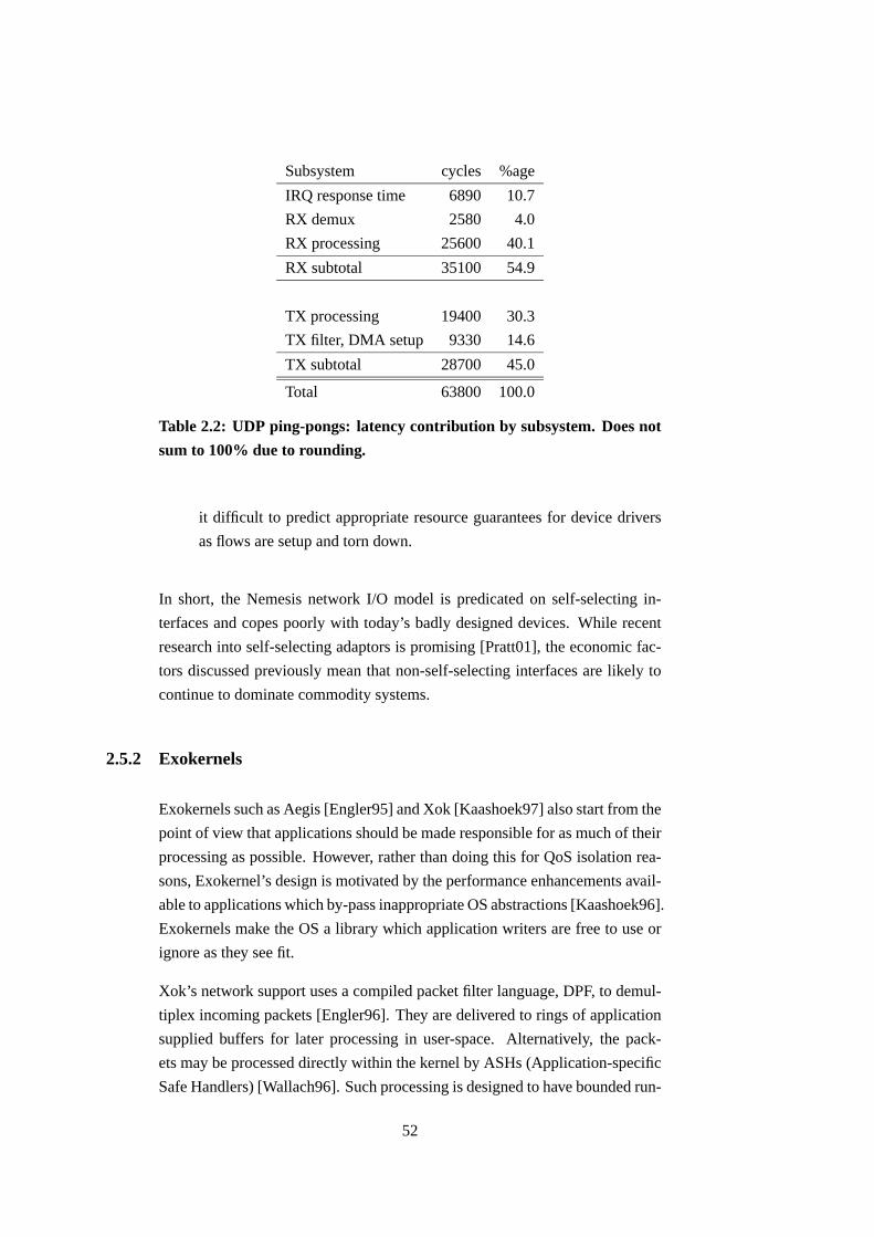
Subsystem cycles %age
IRQ response time 6890 10.7
RX demux 2580 4.0
RX processing 25600 40.1
RX subtotal 35100 54.9
TX processing 19400 30.3
TX filter, DMA setup 9330 14.6
TX subtotal 28700 45.0
Total 63800 100.0
Table 2.2: UDP ping-pongs: latency contribution by subsystem. Does not
sum to 100% due to rounding.
it difficult to predict appropriate resource guarantees for device drivers
as flows are setup and torn down.
In short, the Nemesis network I/O model is predicated on self-selecting in-
terfaces and copes poorly with today’s badly designed devices. While recent
research into self-selecting adaptors is promising [Pratt01], the economic fac-
tors discussed previously mean that non-self-selecting interfaces are likely to
continue to dominate commodity systems.
2.5.2 Exokernels
Exokernels such as Aegis [Engler95] and Xok [Kaashoek97] also start from the
point of view that applications should be made responsible for as much of their
processing as possible. However, rather than doing this for QoS isolation rea-
sons, Exokernel’s design is motivated by the performance enhancements avail-
able to applications which by-pass inappropriate OS abstractions [Kaashoek96].
Exokernels make the OS a library which application writers are free to use or
ignore as they see fit.
Xok’s network support uses a compiled packet filter language, DPF, to demul-
tiplex incoming packets [Engler96]. They are delivered to rings of application
supplied buffers for later processing in user-space. Alternatively, the pack-
ets may be processed directly within the kernel by ASHs (Application-specific
Safe Handlers) [Wallach96]. Such processing is designed to have bounded run-
52

0
10
20
30
40
50
60
70
0 2 4 6 8 10 12 14 16 18
Per
cent
age
of C
PU
(10
s av
erag
e)
Number of flows or steps
A: demux, 1.18Mb/s flowsB: no demux, 1.18Mb/s stepsC: demux, 0.589Mb/s flowsD: no demux, 0.589Mb/s steps
Figure 2.10: Driver CPU usage vs. flows.
time, however it occurs within the kernel on packet receipt and is not scheduled.
While individually an ASH may be innocuous, in a NEOS many ASHs would
be expected to be active concurrently and their cumulative effect can grow to
represent a sizable unscheduled workload on the system.
Packets are transmitted by handing wire-ready frames to the kernel which sends
them without performing any source address checking or bandwidth schedul-
ing. This minimal support is consistent with Exokernel’s focus on the efficient
multiplexing of multiple library OSes above the hardware, but it completely
ignores resource accounting and scheduling.
2.6 Active networks
In recent years, not many genuinely new operating systems have been devel-
oped [Pike00]. In part, this is due to the large body of legacy applications one
wishes to run on an operating system, which constrains the APIs which can be
offered. This interoperability problem is mitigated in operating systems for net-
work elements because existing protocols are normally well-documented and
there are well-understood mechanisms for deploying new protocols alongside
53

existing ones; the set of “applications” is smaller and better defined.
This lower barrier to entry, along with recent work in Active Networks has
renewed interest in Network Element Operating Systems: researchers have
agreed on a NodeOS design [Peterson01] to act as a common platform for ac-
tive network experimentation. A NodeOS is a NEOS which runs EE (Execution
Environment) sandboxes within which untrusted code may be executed, usu-
ally in the form of bytecode [Wetherall98, Moore01]. Active networks cover
a spectrum of possibilities, ranging from automated firmware updates on man-
agement timescales, via per-connection code installation, all the way to code
run on per-packet timescales.
Resource control in a NodeOS can be done in a variety of ways. Basic control
can be achieved by deliberately restricting the power of the bytecode language,
for example removing looping constructs to ensure that run time is proportional
to code length, as is done in the SNAP scheme. More sophisticated control
can be achieved by using similar techniques to those used in soft real-time or
multimedia workstation OSes [Menage00].
Irrespective of the precise higher-level functionality presented to the network
or the user, Active Network EEs need to perform resource control on the code
they run. This means that they would benefit from being implemented over a
NEOS which supports accurate resource control natively.
The RCANE system [Menage00] is an architecture for just such a NEOS, ca-
pable of simultaneously hosting and isolating multiple EEs. However, because
it relies on OCaml bytecode to ensure protection between EEs, all environ-
ments must be implemented in languages which can be complied down to
the OCaml bytecode. This restriction meant that off-the-shelf EEs such as
the Java-based ANTS Toolkit needed to be re-implemented before they were
runnable on RCANE. By contrast, the system described in this dissertation runs
native machine instructions which serve as a lingua franca for all high-level
languages, allowing pre-existing bodies of code to be reused.
In conclusion, EEs are a class of application which would benefit from being
implemented over a resource-controlled NEOS.
54

2.7 Smart devices
Commodity PC workstations are the hardware platform of choice for the ma-
jority of open programmable routers today, and it is not difficult to see why:
they offer plentiful cheap processor cycles, storage, and reasonable I/O per-
formance. In addition to this, their widely documented architecture allows a
competent programmer to target an OS for them with relative ease.
While the hardware’s I/O architecture is primitive compared to that of a main-
frame, this is not such an issue for two reasons. Firstly, having the main CPU
closely involved in directing I/O allows a great degree of flexibility in how
such I/O is managed, and this is naturally of interest to those implementing
open programmable routers. Secondly, there is a general trend towards more
powerful and flexible devices.
Evidence for this move towards more complex devices can be seen as early as
the work on Jetstream/Afterburner [Edwards95]. More recently, [Pratt97] ar-
gues for the offloading of the OS protection and multiplexing functions directly
onto devices, thus allowing them to be accessed safely by untrusted users.
[Fiuczynski98] describes an operating system for a smart device which can
be safely extended by untrusted users.
In a commercial setting, Alteon Web Systems have produced a very flexible
gigabit Ethernet chipset [Alt97]. A typical configuration consists of two MIPS
R4000-compatible processors and 1MB of RAM, allowing around 500 cycles
of processing to be performed per packet. [Pratt01] describes how this cycle
budget can be used to demultiplex incoming flows directly to the appropriate
user process and enforce per-flow transmit rate limits, so allowing safe user-
level access to the device.
This trends towards smarter devices with considerable CPU power and mem-
ory is evinced further by Intel’s IXP1200 network processor [Int01]. This is a
more aggressively parallel architecture than the Alteon described above: a sin-
gle IXP1200 chip has 6 micro-engines managed by a single StrongARM core.
The micro-engines perform data path manipulations such as TCP checksum of-
floading, and post events to the ARM core when more extensive processing is
required. A typical switch or router built using these on line cards would almost
certainly have a further processor to manage the system, leading to a three-tier
hierarchy of processing power: (1) route processor, (2) ARM cores, (3) micro-
engines. From top to bottom the amount of power available decreases while
55

the proximity to the data stream increases.
Both smart devices like the Alteon and more complex CPU hierarchies like the
IXP1200 can be emulated on multiprocessor workstations by dedicating one
(or more) CPUs to I/O tasks, rather than using them in the more common SMP
(Symmetric Multi-Processing) arrangement [Muir98, Muir00].
These processor hierarchies come about because for technical or administra-
tive reasons, device vendors wish to isolate the resources used on their device
from others in the system. While dedicated hardware is certainly effective in
segregating processing, the correct resource balance needs to be statically de-
termined at hardware design time. This is unsuitable if the system is ever to
change role since it is likely that the processing balance between components
will be different from the initially-provisioned system. By using scheduling in
the OS to make the resource split, the system remains flexible.
For example, software modems have recently become popular for cost reasons
because the host processor is responsible for implementing higher level proto-
col features and often lower level signal processing. The OS must isolate of
the driver from the rest of the system to achieve correct operation of the de-
vice. Often software modem device drivers will not trust the OS to schedule
them correctly, and so they disable interrupts to ensure they are not preempted.
This is a really a symptom of inadequate scheduler support for hard real-time
processing. Alternatively, some drivers take no steps to ensure they are appro-
priately scheduled and hope that the system is lightly loaded, which results in
mysterious malfunctions when this assumption breaks down. A NEOS with a
real-time scheduling facility could correctly handle such devices, and would
allow a dial-in server consisting of many modems to be built more cheaply by
using software modems rather than full hardware implementations. An added
benefit is that new line coding schemes can be introduced simply by updating
the drivers.
By analogy with the modem example, smart Ethernet devices cost more than
dumb devices but are more easily virtualised. If many Ethernet interfaces are
needed in a single system then an implementation using dumb devices and a
proper resource controlled NEOS which can emulate a smart API over them
will lead to a cheaper, more flexible system. This is covered in Chapter 4.
Resource control in systems with multiple, asymmetric, processors is an in-
teresting problem, but not the main focus of this dissertation. The problem is
briefly considered in Section 7.4.
56

2.8 Summary
The rise in use of middle boxes and active networks means that increasingly,
processing is being moved into the network. Current routers and switches
perform only outbound link bandwidth scheduling, so are unsuited as a plat-
form on which these more complex services may be built. Current OS designs
are poorly adapted to an I/O-centric workload, and although a number of re-
searchers have investigated promising path-based scheduling schemes, these
are not flexible enough to also schedule the background computations needed
in a realistic environment. A middle-ground is sought, blending traditional
task-based scheduling together with I/O-driven path-based scheduling in order
to correctly account and isolate the processing performed on resource-strapped
intelligent network nodes.
This dissertation presents the Expert OS,4 an operating system designed with
these issues in mind. Expert draws on the ideas of the Nemesis OS, which are
described in greater detail in the next chapter.
4“Expert” is an acronym: EXtensible Platform for Experimental Router Technology
57

Chapter 3
Nemesis
As Expert is substantially based on Nemesis, this chapter presents a brief sum-
mary of the main concepts embodied in Nemesis. Readers already familiar
with Nemesis may wish to skip this chapter as no new work is described here.
Nemesis is an operating system for multi-service workstations. It is designed to
facilitate the accurate resource accounting and fine-grained scheduling needed
to support the processing of time-sensitive data such as audio or video streams.
Nemesis is vertically structured, i.e. applications are made responsible for as
much of their own processing as is compatible with the need to retain system
security. The entire operating system is structured to this end, redefining the
kernel-user boundary.
3.1 NTSC (Nemesis Trusted Supervisor Code)
The NTSC is Nemesis’ kernel. It exists only to multiplex the CPU and memory
between domains,1 and provides only a very basic event sending mechanism
for cross-domain communication. The NTSC converts CPU exceptions such
as page faults into events sent to the faulting user domain, thus allowing user
domains to perform their own paging [Hand99].
Nemesis is a single address space OS. This simplifies communication, since
pointers can be passed unmodified from one domain to another, although note
that just because Nemesis uses a single address space does not mean it lacks
1Described in Section 3.3.
58

kernel
irq / exn
app 1
libc
app 2
Key:
supervisor modeprotection domain
address space
code module
extent of threadexecution
user modeprotection domain
Figure 3.1: Structure of Nemesis.
memory protection – if a pointer references memory which is not readable by
the current domain then an attempt to dereference it causes a protection fault.
Another advantage of using a single address space is that it eliminates the need
to flush virtually-addressed caches on context switches, thus allowing higher
context switch rates to be used without adversely affecting overall system per-
formance. Frequent context switches allow device drivers to be scheduled no
differently than standard user domains.
Figure 3.1 shows how Nemesis uses its single address space. It contains mul-
tiple protection domains within which applications run, perhaps using shared
libraries. This diagram is included to aid comparison with the other operating
systems previously described in Chapter 2.
3.1.1 Interrupts
Interrupts may be reserved by privileged device driver domains. Once claimed,
the NTSC handles that interrupt by running a driver-supplied function, which
typically does nothing more than send an event to the driver domain, making it
runnable. The NTSC then masks the interrupt and performs a reschedule, only
selecting the device driver to run if it is within its guarantee. Eventually the
59

driver’s event handler thread is run, performing any device-specific actions and
unmasking the interrupt.
Note that the CPU scheduler decides when to run a driver domain based on
its guarantees; it is not run directly in response to the interrupt. While this
increases the interrupt handling latency, it allows time spent within the device
driver to be bounded. Because the interrupt remains masked until explicitly
re-enabled by the driver, further device activity does not interrupt the CPU,
reducing the potential for livelock.
3.1.2 API
The NTSC is sufficiently small that its entire API may be summarised here. It
can be broadly divided into two categories: a passive API with no synchroni-
sation between the user domain and NTSC, and a more traditional active API
using system calls.
Passive API
The NTSC exports a read-only PIP (Public Information Page) globally at a
well known address, allowing the cheap publication of system-wide informa-
tion such as the current system time, enabled CPU features, and performance
counters.
Each domain has a DCB (Domain Control Block) split into two: a read-only
(dcb ro) and a read/write (dcb rw) portion. The dcb ro is used by the
NTSC to publish information to the user domain, such as its domain id, current
privileges, event endpoints, and memory manager bindings. The dcb rw is
written to by the user domain to communicate back to the NTSC, in order to
specify activation-related information (see Section 3.2) and memory manager
state. The dcb rw also holds an initial stack, and maintains event state.
Active API
The NTSC also makes available a number of system calls to manage the ma-
chine, interact with the scheduler, send events, perform low-level console I/O,
manage memory, and mask/unmask interrupts.
60

3.2 Scheduler activations
Recognising that individual applications can benefit from tailored thread sched-
ulers, Nemesis allows user applications to schedule their own threads. The
NTSC uses a scheme based on scheduler activations [Anderson92] to allow
efficient user-level thread schedulers to be implemented.
While traditional OSes virtualise the CPU, attempting to hide preemption from
user processes, scheduler activations can expose each OS-level reschedule. A
user process has an activation handler which is upcalled by the kernel when-
ever the process is given the CPU. This activation vector is typically set to the
process’s thread scheduler entry point. While this runs activations are disabled
to avoid the need for a re-entrant thread scheduler. When activations are dis-
abled and a process is preempted, its context is saved in a reserved context
slot. When the CPU is later given back the this process, it is resumed from the
reserved context slot.
The activation handler upcall can terminate in a number of different ways. The
upcall can finish by re-enabling activations and continuing, or more commonly
by atomically re-enabling activations and restoring a previously saved thread
context. The upcall can also choose to re-enable activations and block waiting
for events or a timeout: this is used when the user-level thread scheduler has
decided that there are no currently runnable threads.
3.3 Protection, scheduling and activation domains
Nemesis distinguishes the three related but distinct concepts of protection,
scheduling, and activation domain, called pdom, sdom, and adom respectively.
A Nemesis domain runs with memory privileges granted by its pdom (protec-
tion domain); it is scheduled according to the resource guaranteed to it by its
sdom (scheduling domain); and it is entered at the location defined by its adom
(activation domain).
A protection domain defines the permissions on virtual address ranges; it does
not define a translation from virtual to physical addresses. Permissions include
the usual read, write and execute bits, as well as a meta bit. When set, the
meta bit allows the other bits to be modified, allowing primitive access control.
There is one special protection domain which is used to specify global access
61

rights. A Nemesis domain’s memory access rights are thus the union of its own
pdom and any further global rights.
A scheduling domain is the entity dealt with by the kernel scheduler. An sdom
has a CPU time guarantee specified by the triple (p, s, l) and a boolean flag x.
The sdom receives a guaranteed slice of s nanoseconds in every period p, with
a latency of no more than lns between becoming eligible to run and actually
receiving the CPU. If the boolean x is true, it means the sdom is eligible to
receive a share of any slack time in the system.
An activation domain is the entity which is activated by the kernel. This com-
prises the address of an activation handler, and the state used by the activation
handler to make its user-level scheduling decisions. Nemesis only ever uses a
single adom with each sdom, however the concepts remain distinct.
When the word “domain” is used by itself, it means a Nemesis domain con-
sisting of one each of the above components. Chapter 5 examines the con-
sequences of binding pdoms to code modules and allowing sdoms to migrate
between them.
3.4 Same-machine communication
Another benefit of having a single address space is that sharing data is easy:
marshaling is kept to a minimum, and pointer representations are identical
across pdoms. Nemesis builds rich inter-domain communication facilities over
the basic event send mechanism provided by the kernel.
3.4.1 IDC (Inter-Domain Communication)
Servers export typed interfaces described by an IDL (Interface Definition Lan-
guage). Clients bind to server interface offers, at which time a buffer shared
between client and server is allocated with appropriate permissions, and two
event channels are connected so the server can block waiting for incoming
calls, and clients can block waiting for a server reply.
When a client makes a call to a server, the client marshals its arguments into the
pre-negotiated buffer and sends the server an event. This unblocks the server
which parses the call number and any arguments, invokes the operation, and
marshals any results back into the buffer before finally sending an event back
62

to the client to notify it the call has completed. Since clients marshal their own
arguments, servers cannot assume the arguments are correctly formatted and
must parse them with care.
The Nemesis typesystem includes provision for runtime type queries, type-
cases, and reflection, all implemented over C’s native typesystem by macros
and programming conventions. New interfaces may be added to the system at
runtime, since the default marshaling system uses interface reflection to dis-
cover the number and shape of method arguments. This also allows shells to
make arbitrary interface invocations without needing the interfaces to be avail-
able at build time [Roscoe95].
3.4.2 CALLPRIV sections
A CALLPRIV is a small critical section of code which trusted domains such as
device drivers can insert into the kernel to make some function available to all
domains in the system via the ntsc callpriv() system call. They are run
with the CPU in supervisor mode, with full access to all memory and interrupts
disabled. Naturally, this means they cannot be preempted by the scheduler, so
they should run for a minimum amount of time.
For example, the framebuffer subsystem registers a CALLPRIV which untrusted
clients use to write to the framestore. The CALLPRIV accepts a tile of pixel data
and a location, checks the client is allowed to write to the co-ordinates given,
and if so masks the client pixels against an ownership bitmask and updates the
framestore.
They can be viewed as “custom CPU instructions” which drivers make avail-
able to the system. Like an instruction, they are atomic with respect to inter-
rupts, however this means their scope is limited to time-bounded code portions.
3.4.3 I/O channels
When bulk data needs to be passed between domains, there are two possibil-
ities open to the programmer. Firstly, they can use the normal IDC system to
pass the data either inline or via a pointer to a stretch of memory accessible in
the destination domain. However this is a synchronous operation between the
producer and consumer; by buffering multiple payloads before sending them
to the consumer, protection switch overheads can be amortised leading to im-
63

direction of data transfer
producer consumer
data area
queue of empty buffers
queue of full buffers
Figure 3.2: An I/O channel.
proved throughput. This section describes this second, asynchronous, style of
I/O, and Nemesis’ support for it by I/O channels [Black95].
I/O channels are a connection-based unidirectional packet I/O system which
integrates: (1) buffer allocation, (2) queueing to amortise context switch over-
heads, and (3) back-pressure. Packets are described by iorecs: vectors of
(base, length) pairs which facilitate the common protocol processing steps of
adding or removing headers without needing to copy packet data.
At connection setup time a data area is allocated with permissions read/write
for the producer, read-only for the consumer. From this data area individual
packet buffers are allocated. In addition, two FIFO queues are used to hold
iorecs describing the packet data to be exchanged between producer and
consumer. Figure 3.2 shows this arrangement. The bottom FIFO holds empty
buffers from the consumer to the producer, which fills them with the payload
it wishes to transfer. The top FIFO holds these filled buffers en-route to the
consumer.
The FIFOs decouple the producer and consumer from each other, meaning that
queueing a full or empty buffer for transfer is unlikely to cause a context switch
immediately. The limited FIFO depth provides all four back-pressure points
needed:
• Producer underflow. Blocking the producer when there are no remain-
ing empty buffers (bottom FIFO empty).
• Consumer underflow. Blocking the consumer when there is no data
(top FIFO empty).
64

• Producer overflow. Blocking the producer when the consumer has yet
to collect valid data (top FIFO full).
• Consumer overflow. Blocking the consumer when the producer has yet
to collect empty buffers (bottom FIFO full).
If the producer and consumer operate at different rates, then only two of these
four conditions will be regularly exercised. This makes it easy to forget the
other two block conditions, and leads to subtle bugs. All four block conditions
must be correctly implemented in a general system.
3.5 Network stack
Originally, Nemesis used a port of the x-Kernel as an expedient way of getting
a network stack. However, this suffered from the problems common to any
protocol server in a micro-kernel based system: because applications must ex-
change payload data with the protocol server in order to perform network I/O,
the protocol server itself becomes a point of resource contention and leads to
QoS crosstalk between data flows.
The network stack was re-designed following the Nemesis philosophy of push-
ing as much functionality as possible into applications as possible. I imple-
mented this new native network stack. Its main features are outlined below; a
fuller discussion has been published previously [Black97].
Figure 3.3 shows the organisation of the main components of the network stack.
Dotted boxes surround independently scheduled domains, while dark arrows
represent I/O channels (and show the direction of data transfer). Two applica-
tions have a total of three bi-directional flows directly connected to the device
driver domain. These flows were set up by the applications performing IDC
to the Flow Manager domain. The Flow Manager is the central control-plane
entity responsible for flow setup and teardown, port allocation, ARP cache
maintenance, and routing.
3.5.1 Receive processing
Packets arriving cause the hardware to generate interrupts which are converted
to events, making the device driver domain runnable. When the CPU sched-
65

sharedprotocol
code
FlowManager
applicationcode
network card driver
packet filter demux
applicationcode
shar
ed p
roto
col c
ode
shar
ed p
roto
col c
ode
flow setuprequests
filterinstallation
user space
kernel
hardwareirq
event delivery
Key: Domain
Figure 3.3: Overview of the Nemesis network architecture.
uler next allows it, the device driver runs and uses a table-driven demultiplex
to discover which flow the packet is destined for. If no applications have reg-
istered an interest in the packet, it is delivered to the Flow Manager so it can
reply with an ICMP Port Unreachable in response to unwanted UDP packets,
or a TCP reset (RST) packet for unwanted TCP segments. Non-IP packets are
silently discarded at this stage as well.
Assuming the demultiplex identified a flow, the data is copied from the DMA
receive ring into the flow’s application-supplied buffers, splitting the header
out into the first rec if multiple iorecs are available. The header size is de-
termined as part of the demultiplex operation, and will typically include all
headers up to OSI layer 4 (transport). If the I/O channel has no free buffers
available, then the application is not processing received data fast enough. In
this case, the device driver discards the received packet. This discard happens
before any protocol processing has occurred, and is early enough to provide
some measure of protection against traffic flooding [Black97, Figure 7].
Raw Ethernet frames are delivered to the application, making it the applica-
tion’s responsibility to perform receive protocol processing such as consistency
66

checking and checksum verification, fragment reassembly, and Ethernet frame
padding removal. Should the application wish to forgo such sanity checks (e.g.
for performance reasons), it may directly access the payload delivered in the
second iorec without examining the headers at all. Such behaviour would be
a gross violation of RFC1122 (Host Requirements),2 but may be expedient in
purely local networks with low bit error rate datalink layers.
3.5.2 Transmit processing
Similarly, applications are also made responsible for formatting their own wire-
ready Ethernet frames. For programmer convenience, shared libraries are pro-
vided which implement the standard protocols. These libraries encapsulate the
application-supplied payload with appropriate headers, and queue the packet in
the I/O channel to the device driver.
The device driver domain performs two functions. Firstly, it verifies the frames
presented to it for transmission to ensure that they show the correct prove-
nance. This is done by a simple offset plus value and mask filtering technique,
asserting that particular values such as protocol type and source address/port
are the required ones for this I/O channel. This is fairly efficient since the
driver already knows which channel it is working on, and can directly find the
associated transmit filter to be applied.
The device driver’s second function is to schedule packets from I/O channels
based on QoS parameters expressed in a similar fashion to the CPU param-
eters: (p, s, x). Note that the resource being scheduled is not network band-
width, since with Ethernet there is no reservation mechanism. Instead, the
resource scheduled is the opportunity for this I/O channel to transmit frames
for s nanoseconds out of a period p. Once all I/O channels have been granted
their guaranteed allocations, any channels with the x flag set are then given
round-robin access to the media. This unified scheduling model for both CPU
and network bandwidth is fairly simple to understand. Peak rates can be limited
by setting the slice to one Ethernet frame packetisation delay, and the period
to be the minimum desired mean inter-frame start time. In practice, since the
packetisation delay depends on the frame size, this does not give good results.2In particular, it would violate at least sections 3.2.1.1 (IP version must be checked), 3.2.1.2
(IP header checksum must be verified), 3.2.1.3 (must discard mis-delivered IP datagrams);
3.2.1.8 (must pass IP options to transport layer), 3.2.1.8c (source route option); 3.3.2 (must
reassemble IP fragments); 4.1.3.4 (must validate UDP checksum), and 4.1.3.6 (must discard
mis-delivered UDP).
67

3.5.3 Control plane
The Flow Manager domain is a trusted system server which has both an active
and a passive role. In its active role, it responds to packets which are otherwise
unclaimed and require a response, as described earlier. It also performs ARP
and caches the results on behalf of applications, thus ensuring that untrusted
applications cannot poison the ARP cache. In its passive role, the Flow Man-
ager maintains the routing table which applications consult to decide which
interface to connect through. It also performs TCP and UDP port allocation to
ensure no two applications are allocated the same port.
The Flow Manager also uses the port tables to instantiate the packet filters
needed when it causes new I/O channels between applications and devices
drivers to be established.
Nemesis was designed as a host OS, and its network stack reflects this. There
is no provision for the forwarding of IP datagrams, mainly because the table-
driven receive packet filter performs exact matches only. This means it is not
suitable for the longest prefix matches needed to discover the outgoing interface
for packets with destination addresses which are not local.
3.6 Summary
This chapter has briefly described Nemesis. It has shown how domains interact
with the kernel in a minimal fashion, building their own abstractions over the
low-level primitives offered by the NTSC.
It has introduced the separate notions of scheduling domain and protection do-
main, despite the fact that Nemesis domains always consist of exactly one sdom
and one pdom.
It has shown how Nemesis supports bulk packetised I/O, and how this facility
may be extended into a network architecture where device drivers safely export
a raw packet interface directly to untrusted user applications.
Section 2.5.1 argued that Nemesis is not directly suitable for use as a network
element OS. The next two chapters describe the problems faced in designing a
NEOS capable of offering resource control, and how Expert resolves them.
68

Chapter 4
Network device driver model
This chapter describes how network devices are handled in the Expert archi-
tecture. It discusses design trade-offs and presents evidence that shows it is
possible to achieve good performance while preserving isolation between sim-
ple processing of data flows. Isolation is desirable because in an overloaded
system, it enables meaningful resource guarantees to be given.
This chapter concentrates on the network device driver model because it has
such a large effect on the overall performance of the system. Expert’s per-
formance goal encompasses not just the usual metrics of low latency, high
bandwidth, and high packets per second; but also includes isolation, for ex-
ample limiting the jitter clients experience due to the activities of each other,
and ensuring that all clients make progress (i.e. none suffer from deadlock or
livelock).
Prior work has shown that vertically structured operating systems (and corre-
spondingly, user-space network stacks) allow more accurate resource account-
ing than either monolithic kernel or micro-kernel systems [Black97]. For ex-
ample, by placing protocol processing in the application and using dedicated
application-supplied receive and transmit buffers, the Nemesis network stack
can control the resources consumed by packet communications on an Ether-
net. However, Nemesis uses a user-space device driver to demultiplex received
packets and rate-limit transmissions, effectively placing a shared server on the
data path.
Shared servers on the data path introduce three problems: firstly, they compli-
cate resource management, since both application and server resource guaran-
69

tees need to be set appropriately. Secondly, shared servers degrade performance
by increasing the number of context switches (and thus protection switches and
expensive cache invalidations) needed, which directly increases the latency ex-
perienced by packets traversing the system. Finally, shared servers need to be
carefully coded to ensure they internally schedule their clients in order to avoid
crosstalk between them. Section 2.5.1 presented results demonstrating the first
two of these detrimental effects in Nemesis (see Figure 2.10 and Figure 2.9 in
particular); because Nemesis drivers schedule their clients they do not suffer
from excessive crosstalk, the third disadvantage of shared servers.
Expert uses two complementary mechanisms to avoid such shared servers.
Firstly, some device driver functionality is moved back into the kernel. Sec-
ondly, a limited form of thread tunnelling is introduced, allowing paths to
execute server functions using their own guarantees. A single system-wide
scheduler arbitrates the allocation of CPU time between both paths and tasks,
allowing data-driven processing to be scheduled on an equal footing with tra-
ditional compute bound tasks.
Expert’s design is described in two stages: basic interaction with network de-
vices is covered in this chapter while the thread tunnelling sub-system used by
paths is covered in the next chapter.
4.1 Receive processing
The fundamental problem in managing network devices is the following: until
an incoming packet has been classified, any resources expended in processing
it (e.g. CPU cycles or buffer memory) cannot be scheduled properly.
The best solution would be to use self-selecting devices capable of classify-
ing incoming packets in hardware [Pratt01], thus providing a hard partition
between classification processing and the host CPU. As discussed previously
in Section 2.5.1, such devices are unfortunately not common. The rest of this
section describes how to best cope with non-self-selecting devices; when self-
selecting devices become widespread, it is likely that the techniques described
here can moved out of the kernel and into the device.
Assuming non-self-selecting interfaces, the host CPU must expend resources
in classifying and buffering packets. How should these resource be accounted?
Accounting resource usage in arrears allows retrospectively accurate account-
70

kernel
user
h/w
(b) Nemesis
probe,control,RX, TX,demux
app
stack
(c) Expert
RX, TX,demux
app
probe,control
stack
(a) Unix
stack,probe, control,
RX, TX,demux
app
Figure 4.1: Network device driver models.
ing, but it cannot be used for scheduling purposes since any action taken on the
basis of such information would be out of date. This approach is not considered
any further.
Having accepted that it is impractical to account the cycle cost of demultiplex-
ing to the flows themselves, we are left with two options: either the costs are
accounted to a stand-alone driver entity, or the costs are distributed as evenly
as possible amongst all scheduling principals. User-space device drivers under
Nemesis are an example of the first of these; Unix-style drivers where interrupts
are handled in the context of the interrupted process epitomises the second ap-
proach (assuming smooth arrivals).
Expert’s contribution is to emulate a smart device by performing receive de-
vice handling and demultiplexing in the kernel directly in response to network
interrupts. This shares the cost of emulating a self-selecting device amongst all
processes as in the Unix model. Figure 4.1 shows for each device model the
location where card-specific receive processing (RX), demultiplexing (demux),
protocol processing (stack), and transmit scheduling and device handling (TX)
occurs. The location of code dealing with device discovery (probe) and man-
agement (control) is also shown. Management of a device means configuring
its demultiplex tables, changing transmit scheduler parameters, and gathering
statistics on the device or media (for example, to determine bytes transferred,
number of collisions, or line rate).
Splitting the device driver allows the best features of each of the other models to
be obtained without their accompanying deficiencies. Kernel-resident drivers
71

both minimise interrupt response time and have lower context switch induced
penalties. This is because the arrival of an interrupt causes the CPU to trap to
supervisor mode, so remaining there to run the device driver has lower over-
head than switching to a separate protection domain, running driver code, then
switching back to the originally interrupted protection domain. Modern CPUs
rely on aggressive caching and prefetching of all manner of information (e.g.
branch prediction tables, TLBs, speculative execution, code and data) to yield
their full performance; this trend is unlikely to reverse. Expert is designed to
minimise protection switches, and amortise their cost by performing sufficient
work after a switch: placing the device driver’s data path in the kernel achieves
this goal.
The disadvantage of a kernel-resident driver is that all cycles spent executing
in the kernel are not cycles controlled by the system’s scheduler, so it adds
jitter to user-space processes. Table 2.2 showed that the receive portion of the
Nemesis device driver code is small enough and bounded in time such that the
jitter experienced by user processes is minimal: around 2580 cycles are need to
manage the device and perform a demultiplex. Section 4.4.2 provides further
results quantifying jitter on Expert and comparing it to jitter on Nemesis and
Linux.
One further question remains: should the device be handled by polling it, or
via interrupts? The assumption so far has been that the device posts an in-
terrupt to the kernel to signal the arrival or departure of packets. Polling has
the advantage of limiting livelock [Mogul96], and can lead to low latencies
(depending on polling frequency). On multi-processors machines, one CPU
can be devoted entirely to polled device management, allowing a more sophis-
ticated self-selecting device to be emulated. Such an arrangement would be
substantially similar to the Piglet OS [Muir00]. The disadvantage of reserving
an entire CPU to poll devices is that the resource partition formed is static: by
design, there is no way of allowing spare cycles on the I/O processor to be
used by other system components or user code. Polling schemes fit well into
hard real-time systems, where CPU requirements are known a priori, so that
the devices may be polled in a timely manner.
Clocked interrupts [Smith93] use regular interrupts to trigger device polls, thus
limiting interrupt processing overheads without needing the entire system to
be structured to support polling. The main problem with clocked interrupts is
in deciding how frequently they should be delivered: too fast and the system
degenerates into polling, too slow and the event delivery latency becomes too
72

high.
The wide range of workloads expected to be run over a resource controlled
NEOS is unlikely to offer the a structured execution environment needed for
polling – indeed, part of the motivation for this style of NEOS comes from the
problems with the existing inflexible switch and router OSes of today. Thus,
Expert uses interrupts together with techniques similar to clocked interrupts to
be notified of device events.
Livelock is addressed by a variety of complementary techniques:
Limited interrupt processing. Expert, like other vertically structured operat-
ing systems, makes applications responsible for their own protocol pro-
cessing. This means the only functionality needed in the kernel device
driver is device-specific handling, and packet classification. By delay-
ing further processing to an explicitly scheduled application, the system
scheduler remains in control of processing. The system is not scheduled
by interrupts from network traffic arrivals, unlike event-based systems
such as Scout or Wanda [Black95].
Kernel resident driver. Livelock is caused by interrupts causing large amounts
of fruitless work to be performed. Even if protocol processing is no
longer performed in the interrupt hander, if the device driver is not in
the kernel the cost of context switching to the driver to classify and sub-
sequently discard packets can be considerably larger than the cost of
remaining in supervisor mode and doing the demultiplex and discard im-
mediately. Therefore Expert uses kernel-resident receive processing and
demultiplexing.
Interrupt mitigation. Most current network adaptors such as those based on
the Intel 21143 [Int98] have two interrupt mitigation parameters n and t
which can be used to limit the number of interrupts generated. Instead
of raising an interrupt for every packet received, the hardware generates
one for each batch of n packets. So that the system does not deadlock
when fewer than n packets have been received, an interrupt is also gen-
erated if there are packets outstanding and time t has elapsed since the
previous interrupt was generated. These two parameters together allow
the number of interrupts to be decreased by a factor of n at high packet
arrival rates while bounding the notification latency by t at low rates.
Sadly, many OSes do not use interrupt mitigation because picking appro-
priate values for n and t remains something of a black art. The follow-
73

ing discussion attempts to clarify this guesswork by providing concrete
bounds on sensible parameter settings.
Modelling the system as a DMA queue with maximum depth d, an inter-
rupt response time r, and a minimum packet inter-arrival time i, we get
an upper limit for n:
nmax = d −
r
i
This assumes that the driver can process a packet from the DMA ring
faster than time i (i.e. the arrival rate is less than the departure rate). The
minimum value for n is 1, where the interrupt mitigation scheme degen-
erates into the usual single interrupt per packet. As n approaches nmax,
the probability of queue overrun increases, depending on the variance of
i and r. Since i has a fixed lower bound set by the wire format and r can
be directly measured on a running system, it should be feasible to modify
n dynamically in response to measured system metrics. As n is increased
two other effects become apparent: firstly, more buffers are needed be-
tween the application and device to avoid underrun; and secondly TCP
ACKs arrive in bursts, liberating bursts of data which multiplex poorly
in the network, causing congestion.
The choice for parameter t is wider, since it is purely an expression of
the applications’ tolerance of additional latency. At the lower limit, t > i
otherwise no batching will occur; the upper limit on t is unbounded.
Again, t can be set mechanically assuming that applications provide in-
formation on their latency tolerance. The latency l experienced by an
application is l = t + r, so if ltmin is the minimum of all application
latency tolerances lt requested, then t = ltmin − r. Note that ltmin < r
means there is an unsatisfiable application latency tolerance.
To summarise: Expert locates the receive processing and classification func-
tions of device drivers in the kernel in order to reduce application visible la-
tency, crosstalk in the DMA ring, and livelock.
4.1.1 Demultiplexing data
Once an Ethernet frame has been successfully received by the device driver, the
next task is to discover the packet’s destination. On workstations and servers,
most packets arriving will be for the local machine. However, for a NEOS,
local delivery is assumed to be an exceptional case: the majority of packets
74

will require some processing before being forwarded towards their ultimate
destination.
While on the surface it seems that these two cases are distinct, they can be
unified. In the general form, classification discovers which FEC (Forwarding
Equivalence Class) each packet belongs to. Each FEC has associated parame-
ters specifying outgoing interface, queueing behaviour, and any transmit shap-
ing needed. Local delivery is achieved by defining a FEC with a special “out-
going” interface; packets destined for a local address are classified as belonging
to this FEC, removing this special case from the classification code. To further
reduce special cases, I assume that packets are always a member of some FEC:
packets which are unrouteable (i.e. match no routing table entry) are considered
members of a “discard all” FEC. This may be useful in a default-deny firewall,
where unexpected packets from external interfaces should be discarded.
Note that this says nothing about the granularity at which packets are assigned
to FECs. At one extreme, one FEC per flow may be desirable, for example
if each flow is to receive dedicated queueing resources. At the other end of
the spectrum one FEC may be used per outgoing interface, modelling the be-
haviour of traditional best-effort routers. Intermediate variations are useful
where best-effort traffic is to be handled as one resource class while picking
out specific flows for special processing or preferential queueing.
Expert uses paths to encapsulate the abstract notion of a FEC. A path is a sepa-
rate schedulable entity, with guarantees of CPU time, buffer memory availabil-
ity, and transmit bandwidth. A path also defines a sequence of code modules
which are to be traversed on receiving the packet. Packets are delivered to paths
and tasks via I/O channels. Paths are described in more detail in Chapter 5; this
section concentrates on how packets are demultiplexed to an appropriate I/O
channel.
Classification strategies
The way 4.4BSD demultiplexes received packets is by using branching com-
pares to determine the correct protocol, then using hash tables on source and
destination IP address and port numbers to find an appropriate socket buffer
in which to place the payload for locally terminated connections. For Unix
machines configured as routers, additional processing is performed if the des-
tination IP address is not a local one. Usually some trie-based scheme is used
75

to find the longest prefix in the routing table which matches the destination IP
address [Bays74].
Research over the previous five years or so has been on two fronts, both improv-
ing the performance of this longest prefix match [Degermark97, Waldvogel97,
Srinivasan98a, Nilsson98], and generalising the classification to more dimen-
sions to additionally allow the source IP address and port numbers to determine
forwarding behaviour [Srinivasan98b, Lakhsman98].
Since it seems likely that further improvements will be made in this field, Ex-
pert encapsulates the demultiplexing decision behind a high-level interface, PF,
which may be implemented using any of the techniques cited above (or their
successors). Operations on PF include the Apply() method which takes a
buffer containing an Ethernet frame and returns which I/O channel the frame
is destined for, along with the header length, and IP fragment related informa-
tion (see later). Returning the IP header length enables application data and IP
headers to be delivered to different buffers despite variations in header length,
leading to a performance boost in some circumstances. Determining the header
length as a by-product of the classification stage is an approach which was first
used in the Nemesis network stack and later adopted by [Pratt01], but does not
seem to be prevalent elsewhere.
A separate interface is used to configure the classifier to add and remove pre-
fixes. Tasks and paths supply a 5-tuple specifying protocol, source and des-
tination port ranges and source and destination IP address prefixes. Because
the implementation of the demultiplex step is hidden behind this interface,
tasks and paths cannot directly supply an arbitrary bytecode filter describing
the packets they are to operate on. While less flexible, this insulates applica-
tions from knowledge about the particular classification algorithm in use. This
loss in flexibility is not an issue, since in practice the limited number of pro-
tocols in common use in the Internet and their hierarchical nature means that
arbitrary filters are unnecessary. Also, if a major new protocol were introduced,
the timescale would allow a new version of Expert to be released; a major new
protocol would not need to be supported faster than management timescales.
Classification despite incomplete information
One further problem faced by any demultiplexing scheme is how to handle
frames which do not contain sufficient information to be fully classified. TCP
76

data segments and IP fragments are two examples of such frames: TCP data
segments cannot be associated with a particular flow until an appropriate SYN
packet has been seen, and IP body fragments do not carry port information so
they cannot be classified until the first (or head) fragment has arrived. Expert’s
basic solution is to allow the classifier to delay a decision until more informa-
tion is available (i.e. when the TCP SYN or IP head fragment arrives). The
delayed packet is held in temporary storage until either its destination is dis-
covered, or it is evicted (either by timing out or due to memory pressure). The
remainder of this section uses Expert’s handling of IP fragments as a concrete
example of how classification can still take place despite incomplete informa-
tion.
Most packet filter languages ignore IP fragments: only MPF [Yuhara94] sup-
ports them directly. Other filter languages (for example [McCanne93, Bailey94,
Engler96]) need the filter rules to be modified to explicitly recognise non-head
fragments. Expert’s solution separates fragment handling into three parts: (1)
the demux decision on head fragments, (2) postponing fragments until the head
arrives, and (3) actual reassembly (if any). This separation has the twofold ad-
vantage of insulating the classification algorithm from fragments, and delegat-
ing any reassembly to applications.
Since the head fragment is the only one to include port information, its ar-
rival sets up an additional temporary demux association keyed (in part) on the
IP identity field. This temporary association allows non-head fragments to be
recognised as continuations of the head so they may be delivered to the same
I/O channel. In order to allow a broad range of classification algorithms to be
used, they are not required to support such temporary associations themselves;
they are managed by a fragment pool. The only requirement of the classifi-
cation algorithm is that its Apply() method return a flag which is set if the
frame is an IP fragment, either the head or a body.
Body fragments which do not match any temporary demux associations are
delayed in the fragment pool until their head fragment arrives. The arrival of
the head fragment sets up a new temporary demux association and causes any
delayed body fragments to be delivered to the application for reassembly. Head
fragments which arrive but are discarded by the classifier nevertheless cause a
temporary demux association to be installed in the fragment pool, so that future
body fragments can be recognised and swiftly discarded. Body fragments in the
fragment pool are also discarded if no matching head fragment arrives before
some timeout, or if there is pressure for space.
77

In this manner, rather than attempt a full reassembly (a fairly complex and no-
toriously error-prone procedure), the device driver postpones the delivery of
fragments which arrive out of order until a corresponding head fragment ar-
rives. When it does, the head fragment is delivered to the application, followed
by any further fragments queued. Re-ordering, packet overlap trimming and
the discarding of duplicates is left entirely up to the application to perform in
any manner it chooses, including the option of not performing reassembly at
all should this be useful (as might be the case in a normal non-defragmenting
router). In this way, bugs in reassembly do not compromise the safety of the
system; they are limited to the applications using the particular shared library
with that bug. As far as I am aware, this split between a trusted postponement
stage before demux and a later untrusted reassembly is unique to Expert, al-
though any other system performing early demux and supporting IP fragments
will necessarily need a similar system.
4.2 Kernel-to-user packet transport
Expert’s cross domain packet transport is based on the Nemesis I/O channel
model as described in Section 3.4.3. Packets are described by a vector of
iorecs: (base, length) pairs. Experience with the Nemesis model has led
to two refinements.
Firstly, although Nemesis allows an arbitrary number of (base, length) pairs to
describe a packet, it was observed that this feature is hardly ever used and con-
siderably complicates even the most straightforward code. Since in Nemesis
at most two iorecs are ever used (one for the header and one for the pay-
load), Expert limits packet vectors to two iorecs only. The usual argument
given for why multiple iorecs are needed is that lack of co-ordination in a
modular protocol stack means that neighbouring layers cannot assume space is
available in the packet buffer and so need to link in their own headers written
into private buffers. This line of reasoning does not take into account that the
protocol stack stays fixed once specified and will remain so for the duration of
a particular conversation. This can be exploited so that at stack configuration
time the various protocol layers ensure there is enough space for their headers
in the first iorec by reserving an appropriate amount. This relies on know-
ing the most common header size, which is true of the fielded protocols in the
Internet. Variable length headers (e.g. TCP or IP options) are be dealt with
by reserving for the largest common header size at stack configuration time.
78

The packet classification stage determines the actual header size, and if head-
ers overflow the first iorec they continue in the second, into the application
area. This means that receiving oversize headers is possible, but incurs the ad-
ditional cost of either copying the application payload back over the extraneous
header bytes once they outlive their use, or writing applications which can deal
with the payload arriving at any address. This technique works well for TCP
options, where the connection MSS and SACK capability are negotiated dur-
ing connection establishment, but otherwise options (except SACK) are rare
during the data transfer phase.
The second refinement Expert provides over Nemesis relates to Packet Con-
texts. Packet Contexts are optional in Nemesis, and provide information to the
application-resident stack about original buffer allocation sizes, so that after
topping and tailing occurs, the original buffers may be recovered at a later stage
(most often as part of error recovery). Expert makes Packet Contexts manda-
tory and expands their remit to carry demultiplex-related information such as
the flow and receiving interface’s identifier. In this way Packet Contexts are
similar to MPLS labels. This allows multiple flows to share buffering and be
handled by the same path, while allowing the path to efficiently distinguish be-
tween them. Processing may also be keyed on incoming interface, a facility
particularly useful for firewall or encrypted VPN applications where packets
from “inside” and “outside” interfaces need separate treatment.
The major strength of the Nemesis model is retained: there is a closed loop of
packet buffers between the application and the driver. All buffers are owned
by the application, leading to clear accounting of the memory. The applica-
tion primes the device driver with empty buffers to be filled on packet arrival;
should packets for this application arrive and there are no free buffers the driver
drops the packets, controlling the load and minimising crosstalk to other flows.
The fixed number of buffers in circulation means that memory resources for a
particular application are both dedicated and bounded.
4.3 Transmit processing
Having eliminated the need for a separately scheduled device driver to perform
receive processing, this section now discusses how the same may be done for
transmit processing. The motivation for this is the same as for receive process-
ing: if instead of performing a user-to-user context switch, transmission can be
79

triggered by a trap into the kernel then this should further reduce latency. Again
the small amounts of code involved should not greatly impact schedulability;
evidence that this is indeed the case is presented in Section 4.4.2.
4.3.1 Efficient explicit wake-ups
The model most Ethernet adaptors use is that of a transmit process which once
started by a driver command, asynchronously scans the transmit DMA ring
looking for frames to transmit. If the transmit process completes a full scan of
the DMA ring and finds no work, it stops and raises a status interrupt to inform
the driver of this fact.
The main advantage of this scheme is that the transmit costs scale with the rate
at which packets are queued. If packets are queued infrequently, then the driver
is continually starting the transmit process and being notified that it stops; this
overhead is not a problem since by definition the system is lightly loaded. If
the driver queues packets for DMA faster than they are drained, the driver need
only start the transmit process after queueing the first packet; after this further
packets may be queued without restarting the transmit process until the driver is
notified that it has stopped (when the ring drains). Note that this also minimises
the number of status interrupts generated.
These auto-tuning and self-scaling properties are attractive, so Expert uses a
scheme inspired by this model as Expert’s transmit API between applications
and the kernel-resident device driver. As in receive processing, the guiding
architectural principle here is that of a kernel-based emulation of a user-safe
Ethernet device.
Client applications have their own dedicated transmit queues, implemented as
I/O channels similar to those in Nemesis (Figure 3.2). Expert emulates an
asynchronous transmit process servicing these channels by running a transmit
scan in the kernel at strategic times. The transmit scan checks which user
I/O channels have packets available for transmission and loads them into the
hardware DMA ring, using a transmit scheduler to arbitrate access to the DMA
ring should multiple I/O channels have packets outstanding. Before loading a
packet onto the DMA ring, the transmit scan matches a template against the
packet’s header to ensure the application cannot transmit packets with forged
source address or port.
Network transmission in Expert is a two stage process: firstly the client queues
80

user
kernel
h/w
client client
network
tx ring
transmit scan
tx completeinterrupt
kick_txcallpriv1
2
3
4
Figure 4.2: Expert’s transmit scan.
one or more packet(s) in an I/O channel, then secondly the client explicitly
wakes the transmit scan, much as a device driver needs to explicitly start the
transmit process.
Figure 4.2 shows how the transmit scan is triggered initially by a client mak-
ing a kick tx CALLPRIV (1), and subsequently by the arrival of a transmit
complete interrupt (4). The transmit complete interrupt is raised by the adaptor
hardware when a frame has been transmitted, and causes the driver to do two
things: firstly, the transmitted buffer is returned to the client for re-use; sec-
ondly, another transmit scan is run, potentially loading more packets onto the
DMA ring (perhaps even from other clients’ I/O channels).
This means that once started, the transmit scan is regularly re-run by the trans-
mit complete interrupt, thus polling clients’ transmit queues. As packets leave
the DMA ring, more are loaded onto it. Once all clients’ queues drain, the
transmit scan loads no further packets onto the DMA ring and eventually the
ring clears, leaving the transmit subsystem back in the idle state.
The transmit scan is run as part of handling transmit complete interrupts for ef-
ficiency reasons. Because once started the transmit scan becomes self-clocking,
clients need only perform a kick tx CALLPRIV when there are no items on
the DMA ring (i.e. no transmit complete interrupt is expected). This means the
cost of explicitly waking the transmit subsystem is kept to a minimum when
81
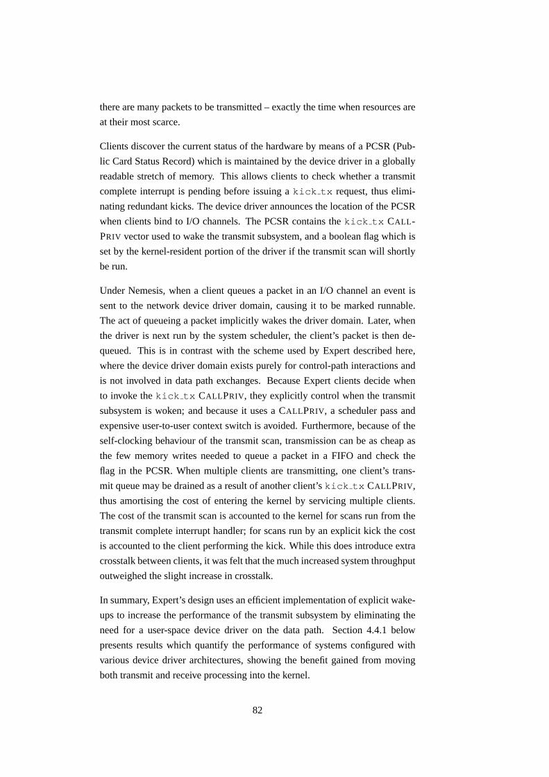
there are many packets to be transmitted – exactly the time when resources are
at their most scarce.
Clients discover the current status of the hardware by means of a PCSR (Pub-
lic Card Status Record) which is maintained by the device driver in a globally
readable stretch of memory. This allows clients to check whether a transmit
complete interrupt is pending before issuing a kick tx request, thus elimi-
nating redundant kicks. The device driver announces the location of the PCSR
when clients bind to I/O channels. The PCSR contains the kick tx CALL-
PRIV vector used to wake the transmit subsystem, and a boolean flag which is
set by the kernel-resident portion of the driver if the transmit scan will shortly
be run.
Under Nemesis, when a client queues a packet in an I/O channel an event is
sent to the network device driver domain, causing it to be marked runnable.
The act of queueing a packet implicitly wakes the driver domain. Later, when
the driver is next run by the system scheduler, the client’s packet is then de-
queued. This is in contrast with the scheme used by Expert described here,
where the device driver domain exists purely for control-path interactions and
is not involved in data path exchanges. Because Expert clients decide when
to invoke the kick tx CALLPRIV, they explicitly control when the transmit
subsystem is woken; and because it uses a CALLPRIV, a scheduler pass and
expensive user-to-user context switch is avoided. Furthermore, because of the
self-clocking behaviour of the transmit scan, transmission can be as cheap as
the few memory writes needed to queue a packet in a FIFO and check the
flag in the PCSR. When multiple clients are transmitting, one client’s trans-
mit queue may be drained as a result of another client’s kick tx CALLPRIV,
thus amortising the cost of entering the kernel by servicing multiple clients.
The cost of the transmit scan is accounted to the kernel for scans run from the
transmit complete interrupt handler; for scans run by an explicit kick the cost
is accounted to the client performing the kick. While this does introduce extra
crosstalk between clients, it was felt that the much increased system throughput
outweighed the slight increase in crosstalk.
In summary, Expert’s design uses an efficient implementation of explicit wake-
ups to increase the performance of the transmit subsystem by eliminating the
need for a user-space device driver on the data path. Section 4.4.1 below
presents results which quantify the performance of systems configured with
various device driver architectures, showing the benefit gained from moving
both transmit and receive processing into the kernel.
82

“Transmit complete” interrupt mitigation
As already described, transmit complete interrupts are generated by the Eth-
ernet adaptor when the transmit DMA ring empties. However, most hardware
allows the transmit complete interrupt to be generated more often than this.
There exists a spectrum of possibilities, going from one interrupt when the
whole DMA ring drains to an interrupt for each transmitted frame, via inter-
mediate choices such as interrupting when the DMA ring is half empty. One
interrupt per frame certainly minimises the latency with which the driver learns
of the success (or otherwise) of transmissions, however the CPU overhead is
increased. Alternately, if the hardware raises an interrupt only once the DMA
ring is fully drained then the outgoing link will lie idle for the time taken to run
the device driver and have it queue further packets onto the transmit ring.
Expert’s solution to this dilemma is to dynamically adjust how often transmit
complete interrupts are raised. This relies on the adaptor having a flag in each
DMA descriptor specifying whether the adaptor should generate an interrupt
once the frame has been transmitted (such functionality is a standard feature of
the Intel 21143 family). When adding a descriptor to the DMA ring, the driver
always sets the new descriptor’s tx-complete flag. It also reads the previous
ring descriptor, and if the frame has not yet been transmitted then the driver
clears the tx-complete flag. In order to avoid the ring draining at high load
when no descriptors would have the tx-complete flag set, it is always set if the
descriptor is at the start or the mid-point of the ring, thus ensuring that the ring
is reloaded regularly.
This ensures that should a number of packets be queued in quick succession
only one interrupt will be generated, at the end of the burst. When packets are
queued into an empty ring slower than the ring’s drain rate then each packet
generates one tx-complete interrupt. In this manner the system automatically
adjusts to conditions, minimising interrupt load at high throughput while retain-
ing low-latency when lightly loaded. While this enhancement was originally
developed by me for Nemesis, I passed the idea and a sample implementation
over to the author of the Linux de4x5 driver and as a result it is now a standard
feature of this widely-deployed driver. Naturally, this feature is also present in
Expert.
83

4.3.2 User-to-kernel packet transport
The I/O channels used by clients to transmit packets need to be different from
standard inter-domain I/O channels for two reasons. Firstly, because the trans-
mit scan (which dequeues packets from client I/O channels) is performed asyn-
chronously from within a transmit complete interrupt, the I/O channel’s en-
queue (PutPkt()) and dequeue (GetPkt()) methods need to be atomic
with respect to interrupts. A second consequence of GetPkt() being invoked
from within the kernel is that a blocking GetPkt() call should never be at-
tempted: supporting blocking within the kernel would require kernel threads
or some other mechanism to preserve CPU context between blocks and subse-
quent wake-ups. Expert does not use kernel threads, keeping the kernel small
and efficient.
The standard I/O channel implementation uses a pair of FIFOs which are them-
selves implemented using event counts designed for synchronisation between
user domains. They are unsuitable for use between user domains and the ker-
nel, and furthermore are over-engineered for the simple non-blocking case re-
quired in this particular circumstance. By only allowing the reading of an event
count’s value, rather than also allowing blocking until a particular value is
reached, the event count implementation need not maintain a list of blocked
threads. With this requirement lifted, a simple integer suffices to provide com-
munication (but not synchronisation) between user domains and the kernel.
These ultra-lightweight event counts are called NBECs (Non-Blocking Event
Counts).
NBECs
An NBEC is the address of a word of memory. Reading the NBEC is simple:
the address is dereferenced to get the event count’s value. Incrementing the
NBEC is only slightly harder: a load, increment, store instruction se-
quence must be run without being interleaved with an NBEC read operation.
In this case, this means without taking an interrupt part way through the se-
quence. On the Intel IA32 and IA64 architectures, this can be achieved with
a lock inc instruction. RISC architectures lack atomic increments of mem-
ory locations, so multiple instructions are required to read, increment and write
back a memory location. Since untrusted applications should not be allowed
to disable interrupts to make such multi-instruction code atomic, the only re-
maining approach is to use cas (compare-and-swap) or ll/sc (load-locked
84

again: ld r1 <- (r0)
add r2 <- r1, #1
cas (r0), r1, r2
jne again
Figure 4.3: Pseudo-code to atomically increment a word.
and store-conditional). For example, Figure 4.3 gives code to increment the
NBEC at the address in r0. If another increment operation modifies the event
count’s value between the load and the cas instructions, then the cas fails, and
the operation is begun anew.
NBECs are directional, like any other event count. The event transmitter must
have read/write access to the memory word used, while the receiver must have
read access to the word. If the transmitter also allocates the NBEC, then this is
easy to arrange: the NBEC may be allocated on any publicly-visible heap the
transmitter chooses. However, if the transmitter deems the values transmitted
to be sensitive, it is necessary to allocate the NBEC on a private heap shared
only with the receiver’s protection domain.
One major restriction of this scheme is that the receiver must trust the trans-
mitter not to make the memory inaccessible at an unfortunate time. Where the
receiver is the kernel, and the transmitter an untrusted client, this cannot be
relied upon. Moreover, cleanly closing NBECs in the event of the death of a
transmitter is also a problem.
There are a number of solutions to this problem, but none of them are particu-
larly compelling. The receiver could catch memory faults resulting from read-
ing a closed (or invalid) NBEC, but this requires much machinery and would
complicate fault dispatching in the common case, for little gain in the rare case
that an NBEC is implicated. Alternatively, NBECs could be defined to require
double-dereference to read or increment, thus allowing a central location (e.g.
the Domain Manager) to mark dead NBECs as such. However, this would need
code similar to that in Figure 4.3 on all architectures to implement both reads
and increments atomically, thus destroying the simplicity which was originally
so attractive.
Therefore, Expert uses the Binder1 to allocate NBECs from its own memory
regions, whose continued availability it can ensure. NBECs have two additional
flag bits describing whether the receiver or transmitter has closed this channel:
1The Binder is a trusted system service used to set up user-to-user event channels.
85

direction of data transferProducer(client,
userspace)
Consumer(driver,kernel)
eventsource
eventsink
eventsink
eventsource
channel 0
channel 1
chan 0chan 1
PutPkt GetPkt
channel 0
chan 1chan 0
channel 1
Keydescriptor forpacket withpayload
descriptor forempty packetbuffer
non-blockingevent channel
blocking eventchannel
PutPktGetPkt
eventsink
eventsource
eventsource
eventsink
Figure 4.4: I/O channel, kernel side non-blocking.
if either are set then the channel has become disconnected and the remaining
endpoint can take action to recover. When such action has been taken, the other
bit is set: channels with both bits set are closed by both transmitter and receiver
and so may be garbage collected by the Binder. The current Expert prototype
only allows allocation of NBECs and discards rather than re-using them when
closed, however this two-bit scheme should solve the problem in an acceptable
manner.
Interrupt-atomic FIFOs and I/O channels
Interrupt-atomic I/O channels are implemented using two FIFOs each with one
NBEC and one standard event count to control access to slots in a shared buffer
as shown in Figure 4.4. There are four “flavours” of FIFO, depending on
whether the producer and/or consumer side is non-blocking. Since only the
kernel side of the I/O channels need to be non-blocking, only two of these
possible combinations are used for user-to-kernel transport in Expert.
The arrangement of blocking and non-blocking event counts is such that when
the producer (the client in user-space) queues a packet for transmission by call-
ing PutPkt(), the client blocks if there is insufficient space left in the top
FIFO. A successful client PutPkt() increments channel 0 (an NBEC) and
thus does not wake the user portion of the device driver. Later the kernel-
resident transmit scan polls the I/O channel by calling GetPkt(), which reads
86

the NBEC but cannot block should the top FIFO be empty. As previously dis-
cussed, blocking is undesirable anyway. When the transmit scan does dequeue
a packet from the top FIFO, it increments channel 1, thus waking the client if
it had blocked in PutPkt() due to a full top FIFO.
At some later stage, the packet’s transmission completes and the buffer is col-
lected by the kernel-resident driver for return to the client as part of the transmit
complete interrupt processing. Now the kernel performs a PutPkt() on the
lower FIFO; the kernel cannot block waiting for space to become available in
the FIFO, but again this would not be desirable. Lack of space is caused by the
client being slow to collect tx acknowledgements, and only affects this single
client, not the entire system. Also, the client can ensure the FIFOs are deep
enough to hold as many buffers as it allocates, so that even in the extreme case
when all packet buffers are awaiting collection by the client they can all fit. So,
assuming there is room in the lower FIFO, the kernel queues the transmitted
packet, and increments the channel 1 event count, thus unblocking the client if
it attempted a blocking GetPkt() when there were no tx acknowledgements
to collect.
In this manner, kernel-facing FIFO interfaces are non-blocking, while user-
facing FIFO interfaces support blocking. Also, the user-space portion of the
device driver is never woken by clients, since the NBECs are explicitly polled
by the kernel in response to a kick tx CALLPRIV. This ensures the user
portion of the device driver is not on the data path, and leads to the performance
benefits described in Section 4.4 below.
Application control over batch sizes
The FIFO between the driver and the application means the cost of trapping
to the kernel can be amortised over multiple packets, at the cost of increased
latency. Because FIFO enqueue and dequeue operations are exposed to the
applications, applications can control whether they operate in batch mode, at-
tempting to process as many packets as possible, or in packet-at-a-time mode,
where latency is minimised at the cost of extra kick tx calls. For example
Figure 4.5 shows latency-optimised code to echo all packets received, leading
to one kick per packet. Figure 4.6 shows the same application re-written to
batch as much work together as possible, leading to higher latencies but fewer
kicks thus making more CPU time available to other applications. Which vari-
ant should be used depends on the specific application’s latency requirements;
87

while(1)
{
IO_Rec recs[2];
uint32_t nrecs;
/* Receive packet. Block until get one. */
nrecs = IO$GetPkt(rxio, recs, 2, FOREVER);
/* Queue it for transmission. */
IO$PutPkt(txio, recs, nrecs);
/* Send now. */
IO$Flush(txio);
/* Collect TX acknowledgement, potentially blocking. */
nrecs = IO$GetPkt(txio, recs, 2, FOREVER);
/* Send empty buffer back to driver for future RX */
IO$PutPkt(rxio, recs, nrecs);
}
Figure 4.5: Latency-optimised packet reflector.
this scheme allows explicit programmer control over the amount of batching.
4.3.3 Transmit scheduling
Although with Ethernet a station’s access to the media cannot be guaranteed,
there are still reasons to schedule individual applications’ access to the media.
Non-local flows may need to conform to a traffic specification in order to meet
an SLA (Service Level Agreement) with the ISP. Within this aggregate, individ-
ual flows may have differing priorities or timeliness constraints. Another use
for transmit scheduling is ACK-spacing, which reduces network congestion.
Scheduling media access by applications allows the NEOS to enforce such
constraints. There exists much prior research on packet scheduling algorithms
[Nagle87, Demers90, Parekh93, Parekh94, Floyd95], and so this dissertation
does not seek to extend this large body of work. Instead it presents a sched-
uler framework, delaying the choice of packet scheduler until system link time.
The framework also simplifies a scheduler’s implementation by separating the
fundamental scheduler algorithm (responsible for selecting which flow should
transmit next) from mundane tasks such as dequeuing the flow’s packet, check-
ing its source endpoint is correct, and enqueueing it on the hardware’s transmit
DMA ring.
Once again, transmit scheduling is a facility which should ideally be provided
88

while(1)
{
IO_Rec recs[2];
uint32_t nrecs;
/* Block waiting for first packet. */
nrecs = IO$GetPkt(rxio, recs, 2, FOREVER);
do {
/* Queue it for transmission (no context switch). */
IO$PutPkt(txio, recs, nrecs);
/* Get next packet or break out if there isn’t one. */
} while (nrecs = IO$GetPkt(rxio, recs, 2, NOBLOCK));
/* Start sending queued packets now. */
IO$Flush(txio);
/* Collect any TX acknowledgements and recycle the buffers. */
nrecs = IO$GetPkt(txio, recs, 2, FOREVER);
do {
/* Send empty buffer back to driver. */
IO$PutPkt(rxio, recs, nrecs);
} while (nrecs = IO$GetPkt(txio, nrecs, 2, NOBLOCK));
}
Figure 4.6: Batching packet reflector.
by smart hardware. Following the Expert architecture, a smart device is emu-
lated by the kernel to allow dumb Ethernet devices to be safely shared amongst
untrusted applications.
Expert’s I/O scheduling abstraction is based on Nemesis, which is in turn based
on the ANSA Project’s concept of an Entry: I/O channels requiring service
are bound to an IOEntry; one or more service threads call the IOEntry’s
Rendezvous() method to collect the next quantum of work to be performed
(i.e. packet), or block if there is no work currently. Thus, an instance of an
IOEntry object encapsulates both the scheduling discipline and the list of
principals (I/O channels) to be arbitrated between.
Expert introduces NBIOEntry as a sub-type of IOEntry; an NBIOEntry
has a Rendezvous() method which instead of blocking the calling thread
returns the time at which the Entry would like to regain control, its wake-up
time. An IOEntry needs to block in two circumstances: either because all
I/O channels have no data pending transmission, or all have exceeded their rate
limit. The wake-up time is the special value infinity in the first case, or the
time when the first rate-controlled flow becomes eligible to transmit again in
the second case.
89

An NBIOEntry is needed because Rendezvous() is called as part of the
transmit scan in kernel mode with interrupts disabled, and thus blocking would
deadlock the kernel. Instead, the transmit scan uses the returned wake-up time
to set a callback to run the transmit scan function again at the wake-up time.
This may involve programming the timer hardware to generate an interrupt at
this time if there is no interrupt already set for an earlier time.
The overall behaviour is that the timer hardware is used to pace outgoing pack-
ets, and thus the granularity of the scheduler is limited only by the system
timer’s resolution. Small inter-packet gaps might require a high rate of timer
interrupts, potentially swamping the CPU. However this is not likely, as this
high timer interrupt rate is needed only when the system has only a single
high bitrate I/O channel active. As more I/O channels become active, the
NBIOEntry needs to block less often since the probability of all channels
being idle or ineligible simultaneously drops, and so fewer timer interrupts are
needed.
Given that transmit scans are run from timer as well as tx-complete interrupts,
a further reduction in the number of client kicks is possible. The PCSR also
contains a timestamp giving the time at which the next transmit scan will run.
This allows latency-aware clients to avoid performing a kick tx if there will
be a scan soon enough to meet their needs. The likelihood is that most clients
will not be latency-aware and thus unnecessary kick tx calls will be made,
however the information is trivial to publish so it is made available anyway.
At high loads the transmit scan will almost always be run from the transmit
complete interrupts anyway, so clients can just check the boolean in the PCSR
rather than performing 64-bit arithmetic on timestamps to discover if a kick is
needed.
A further optimisation Expert makes is that kicks are channel-specific. This al-
lows the NBIOEntry to be notified of individual channels becoming runnable
when previously they had no packets pending. This additional information
means the scheduler implementation can segregate channels into those which
are active, and those which are waiting for more packets from client applica-
tions. By only scanning channels on the active list, the scheduler is made more
efficient in the presence of many inactive channels.
Expert has a number of schedulers provided. The basic round-robin sched-
uler demonstrates how simple a scheduler need be: the complete code for the
Rendezvous() method is given in Figure 4.7, and the remaining code to
90

finish the definition takes approximately 150 lines of boiler-plate.
4.4 Results
This section presents results quantifying the performance of systems using a va-
riety of different device driver configurations, and shows that Expert’s division
of labour allows tight control over both CPU and network resources consumed
by packet flows, without undue penalties in traditional metrics such as latency
or throughput.
Five device driver configurations are measured, exploring all combinations of
transmit and receive processing occurring either in kernel or user-space, and
comparing them to Linux as an example of a system with all components (in-
cluding protocol processing) executing in the kernel.
Linux Version 2.2.16 of the Linux kernel, using version 0.91g of the tulip de-
vice driver. Interrupts, receive processing, transmit processing as well
as protocol processing all occur in the kernel. Linux was chosen as an
operating system which has been extensively tuned, and thus gives a ref-
erence performance achievable on the test hardware when no particular
attention is given to QoS issues.
kRX-kTX This is the configuration that is proposed by this dissertation, the Ex-
pert architecture. Both transmit and receive processing is performed in
kernel mode; no portion of the user-space device driver is on the data
path. Protocol processing occurs in the user application, unlike Linux.
The packets are fully demultiplexed on arrival, rather than being demul-
tiplexed in a layered fashion interleaved with protocol processing, as in
Linux. Also, user applications can transmit without trapping to the ker-
nel because of the transmit scan; Linux requires a kernel trap per packet
transmitted.
uRX-kTX Receive processing is moved to the separately-scheduled user-space por-
tion of the device driver. Device interrupts are converted to events by
the kernel, and all interrupt processing is performed by the user-mode
device driver. Transmissions are handled in the kernel, with user appli-
cations issuing tx kick CALLPRIVs as described in Section 4.3. The
transmit scan is run both in kernel mode via the CALLPRIV or a kernel
91

/*
* Wait for any IO channel to become ready.
* "to" is the absolute time to time out.
*/
static IO_clp Rendezvous_m(NBIOEntry_clp self,
/* IN OUT */
Time_ns *to)
{
nbioentry_st *st = self->st;
bindlink_t *this, *end;
uint32_t nrecs;
/* Scan the binding list starting from the previous binding, and
* return the next one with work to do. */
/* exit if: 1) scanned entire list, but no bindings have work (ret = NULL)
* 2) found binding (ret = binding->io)
*/
this = st->last;
if (!this)
return NULL; /* no bindings registered yet */
end = this; /* get back here => didn’t find anyone */
do {
this = this->next;
if (this == &st->bindings)
this = this->next;
/* Is there work on this IO channel? */
IO$QueryGet(((binding_t*)this)->io, 0, &nrecs);
if (nrecs)
{
st->last = this;
return ((binding_t*)this)->io;
}
} while (this != end);
/* Block for whatever time was passed in: */
return NULL;
}
Figure 4.7: Round-robin transmit scheduler
92

timer callback, and also from user-space in response to transmit com-
plete interrupts. Interrupts are occasionally disabled by the user-level
driver while it runs to enforce mutual exclusion between itself and ker-
nel timer callbacks. Thus, the user-space device driver is on the data
path to handle interrupts and demultiplex arriving packets, but not for
transmission. Protocol processing occurs in the user application.
kRX-uTX Interrupt handling and receive processing happens in the kernel as a di-
rect response to interrupts being raised. Transmission happens in user-
space; user applications queue their data in standard I/O channels, and
the user portion of the device driver services the channels when it is next
given the CPU by the system scheduler. The transmit scan is not used in
this configuration. The user-level portion of the driver blocks a thread in
the network scheduler rather than using a kernel timer triggered callback
to idle during inter-packet send gaps. Protocol processing occurs in the
user application.
uRX-uTX Both transmit and receive are handled in user-space, the kernel does
nothing other than convert interrupts into events sent to the user-level
device driver. This is similar to the classic Nemesis model. The device
driver is fully on the data path, needed for interrupt processing, receive
demux, and transmit processing. Protocol processing occurs in the user
application.
In all the follow experiments, fox (the machine under test) is a 200MHz Intel
Pentium Pro, with 32MB RAM and a DEC DE500BA 100Mb/s Ethernet adap-
tor (which uses the 21141 chipset). Fox runs the appropriate operating system
being tested. The machines meteors and snapper are used as traffic gen-
erators or monitors in some of the following experiments. Meteors is a dual-
CPU 731MHz Intel Pentium III with 256MB of RAM and has an SMC 1211TX
EZCard 10/100Mb/s Ethernet adaptor based on the RealTek RTL8139 chipset.
It runs Linux 2.4.2 SMP with the 8139too driver version 0.9.13. Snapper
is also a dual-CPU 731MHz Intel Pentium III, and has 896MB RAM and the
same Ethernet adaptor as meteors. Snapper runs Linux 2.4.3 SMP and
the same Ethernet driver as meteors. A Cisco Catalyst 3548XL switch con-
nects the test rig together. Since it has a backplane forwarding bandwidth of
5Gb/s [Cisco99] and 48 ports each at 100Mb/s is only 4.8Gb/s, it is effectively
non-blocking in this configuration.
The rationale behind using these faster machines as load generator and monitor
93

station is that it makes overloading the test machine easy, and increases the
probability that the monitoring station will be able to capture packets without
losses. Looking at the behaviour of different systems when they are overloaded
is instructive because this is where differences in architecture matter – if a
system cannot shed load in a controlled fashion then it cannot offer different
service levels, and is vulnerable to denial of service attacks.
4.4.1 Traditional performance metrics
This section examines peak bandwidth, latency, and forwarding performance
for the five systems described above. These metrics are the dominant way of
characterising a network element from an external perspective. Little attention
is paid to QoS metrics; these are fully covered in Section 4.4.2.
Mean sustained bandwidth
This experiment measures the maximum sustainable transmit bandwidth achiev-
able by each test configuration, and whether it depends on the number of clients
competing to transmit. Of interest here is not so much the absolute maximal
bandwidth available, but its jitter – how does the presence of additional clients
affect how smooth their flows are?
The setup is as follows: fox runs between one and six sender clients, each at-
tempting to transmit MTU-sized UDP datagrams as fast as possible. On Expert
and Nemesis the sender clients are given CPU and network scheduler parame-
ters allowing them to make use of any extra time in the system, thus emulating
the best-effort behaviour of Linux; this also ensures that the schedulers do not
artificially limit performance. Snapper runs a listener process for each sender
which discards the received output, and uses tcpdump to monitor the arriving
packets. The packet arrival times are processed to calculate the mean band-
width over successive 200ms intervals, and these bandwidth samples are then
averaged to give an overall mean bandwidth for each configuration. The 95%
confidence interval of the samples is also calculated, giving a measure of the
jitter in the stream.
Figure 4.8 shows how for 1, 2, 4 and 6 competing clients, the bandwidth under
both Linux and Expert is independent of the number of clients: both manage
just under 95.7Mb/s regardless of how many clients compete for the available
94

90
92
94
96
98
100
1 2 4 6
Ban
dwid
th (
Mb/
s)
Number of competing clients
95.7 Expert
LinuxNemesis
Figure 4.8: Mean sustained bandwidth vs. number of clients.
bandwidth. Nemesis’ performance degrades as more clients are added; it is not
clear how its performance might behave with more clients because attempts
to run the experiment with more than 6 clients met with difficulties due to
insufficient memory.
The 95% confidence intervals are more interesting: Nemesis has the largest
(3.9Mb/s), while Linux shows a slightly lower jitter than Expert, having a
confidence interval of 0.05Mb/s (compared to Expert’s 0.07Mb/s). Expert is
marginally faster overall, reaching 95.6Mb/s while Linux gets 95.5Mb/s.
Thus, Linux and Expert are indistinguishable when considering aggregate band-
width. The reality is much different if we compare the behaviour of individual
client flows, however.
Figure 4.9 shows the same 2-, 4- and 6-client experiments discussed previously,
but breaks down the bandwidths into one bar per client. Here we can see that
as the number of competing clients increases, the individual flows increase in
jitter. The 6-client experiment shows the largest difference between the three
OSes, and Linux is seen to share the bandwidth out unfairly, and with large
oscillations between the clients (confidence interval of 10.7Mb/s). Nemesis
is more stable, with a confidence interval of 2.24Mb/s, but Expert is almost
95

0
5
10
15
20
25
30
35
40
45
50
2 4 6
Ban
dwid
th (
Mb/
s)
Number of competing clients
ExpertLinux
Nemesis
Figure 4.9: Per-client bandwidth.
two orders of magnitude more stable than Linux, with a confidence interval of
0.201Mb/s. Furthermore, Expert’s confidence interval is this low regardless of
the number of clients.
Also, neither Expert nor Nemesis dropped any packets, while Linux provided
no back-pressure at all to the transmitting clients. Once more than two clients
were competing for the same output bandwidth, Linux started silently dropping
between 72% and 75% of the packets presented for transmission by clients.
This failure is noted in the Linux sendto(2) manpage:
ENOBUFS The output queue for a network interface was full. This gener-
ally indicates that the interface has stopped sending, but may be caused
by transient congestion. (This cannot occur in Linux, packets are just
silently dropped when a device queue overflows.)
To summarise: Expert can transmit marginally faster, and can share available
bandwidth significantly more fairly and smoothly than either Linux or Neme-
sis. Nemesis has lower jitter than Linux when two or more clients compete for
bandwidth, but lower overall performance.
96

Latency
Low latency of packets traversing a network stack is important because as link
speeds increase, the time spent by a packet queued in a buffer in a NEOS be-
comes a large component of the total end to end latency. Furthermore, since
latency is cumulative, even small latency contributions in a NEOS can add up
to significant delays in the complete network.
Latency varies with load, and should be at a minimum on an unloaded system.
Therefore, this experiment measures the latency of the system under test by
sending a single UDP packet to a user application which simply reflects the
packet back to its source; the system is otherwise unloaded.
The system under test is fox. Meteors runs a UDP pinger application which
writes a sequence number and cycle counter timestamp into each UDP ping
packet sent. When replies are received, their round trip time is calculated from
the cycle counter value in the packets and logged to a file. Several UDP pings
are sent, spaced by around 100ms to ensure the system returns to the idle state,
and the average UDP ping time is plotted. Meteors sweeps through a range
of packet sizes sending 400 pings at each size before moving onto the next.
The UDP payload sizes used are 8, 12, 16, 20, 24, 28, 32, 64, 80, 128, 256,
400, 512, 700, 1024 and 1400 bytes. The predominance of small sizes is to
probe for any special case handling of small packets, for example TCP ACKs.
Also, small packets may arise as a result of cross-machine RPC, where latency
greatly affects overall performance.
Figure 4.10 shows how the UDP ping time for the five systems under test vary
with packet size. The lines all have the same gradient, showing that all sys-
tems have the same data-dependent processing costs, however their different
absolute displacements quantify each system’s per-packet overhead.
The uRX-uTX configuration has the highest per-packet overhead which is un-
surprising given that 3 context switches are required to process each UDP ping
packet. Linux has the lowest overhead, closely followed by Expert. The two
intermediate systems, uRX-kTX and kRX-uTX, are someway between Expert
and uRX-uTX. Looking at the smallest packet size (8 bytes), the gains expected
by calculating the sum of the improvement of each of the two intermediate
systems is 0.156ms, which predicts accurately the measured improvement of
Expert over uRX-uTX of 0.168ms. Expert is better than expected presumably
due to the benefit of entirely eliding the user-portion of the device driver from
97

0
0.2
0.4
0.6
0.8
1
1.2
1.4
0 200 400 600 800 1000 1200 1400
Rou
nd tr
ip ti
me
(ms)
Packet size (UDP payload bytes)
uRX-uTXkRX-uTXuRX-kTX
ExpertLinux
Figure 4.10: Latency: UDP ping time against packet size.
the data path.
Forwarding performance
This experiment characterises the systems’ performance under increasing load.
In this experiment, meteors generates a flow of packets which are received by
fox and forwarded to snapper. The flow ramps up in rate from 1000pps to
19,000pps, sending 600 packets at each rate. The packets are UDP packets with
32 bytes of payload holding sequence number, timestamp and checksum infor-
mation. Meteors logs the send time and sequence number, while snapper
logs the arrival time and sequence number seen, allowing post-analysis of the
logs to calculate the average packet rate over each flight of 600 packets. Both
sender and receiver rates are calculated, and the sequence numbers are used
to match them up. This allows a graph of input rate against output rate to be
plotted.
Figure 4.11 shows how the five systems under test performed as the offered
load was ramped up. Configuration uRX-uTX, with the device driver fully on
the data path, cannot handle more than 3300pps, and in fact as the offered load
98

0
2000
4000
6000
8000
10000
12000
14000
16000
18000
20000
0 2000 4000 6000 8000 10000 12000 14000 16000 18000 20000
Out
put r
ate
(pps
)
Input load (pps)
LinuxExpert
uRX-kTXkRX-uTXuRX-uTX
Figure 4.11: Forwarding performance against load.
increases further actually gets worse, dropping to around 1400pps at loads over
10,000pps.
The intermediate systems (uRX-kTX and kRX-uTX) perform a little better,
managing 3800pps before dropping back down to 2400pps at offered loads
over 10,000pps.
Expert does much better, managing up to 9000pps before losses start to occur,
reaching a peak of 11,500pps before settling back to 9000pps at maximum
load, at which point it is dropping just over 50% of packets sent to it.
Linux does very well, only starting to drop at 12,500pps. However, once over-
loaded Linux suffers very badly from livelock. Overload happens at input rates
somewhere over 17,000pps, and is catastrophic – immediately almost 60%
packet loss is seen. The outlying point where Linux seems to recover is in
fact an unstable data point where Linux is queueing packets faster than it can
drain them, so momentarily it achieves very impressive performance, which
quickly degrades to the cluster of points at around 8000pps on the y-axis.
So, while Expert does not match Linux’s peak performance, Expert manages
better when overloaded and comes close to Linux’s performance. Again, the
99

fact that neither of the intermediate schemes approach Expert’s performance is
due to the fact that the device driver is still on the data path, impeding perfor-
mance.
4.4.2 QoS metrics
Jitter due to kernel resident driver
Because Expert places the data handling portions of network device drivers in
the kernel, this may increase the jitter in CPU guarantees since interrupts are
disabled for longer periods of time. This experiment places a lower bound on
the jitter by measuring how long it takes to process an interrupt for the Ethernet
device. This is a lower bound on user-space visible jitter because while an
interrupt is being processed the scheduler is no longer in control of the CPU,
and so no scheduler would be able to offer guarantees at finer timescales than
the time taken to service interrupts.
Each kernel is instrumented to record the number of cycles it takes to run the
device driver every time it is entered due to an interrupt. These samples are
aggregated and counted to form a distribution. Again, fox is the machine
under test and it runs the instrumented kernel. To load fox, meteors is
configured to send it 32-byte UDP packets with exponentially distributed inter-
send times with a mean of 125µs (corresponding to 8000pps.)
An exponential distribution is picked because measurement of real traffic ar-
riving at my own workstation showed that packet inter-arrival times were ex-
ponentially distributed. The mean is chosen by consulting Figure 4.11 to find a
rate which can be handled by Expert. By picking a load near the middle of the
graph and using an exponential distribution, a wide portion of the load-space is
covered, including rates which Expert cannot handle without dropping packets.
While varying the packet size is also possible, it was felt that the range of loads
explored by varying the arrival rate was sufficient.
The experiment lasts five minutes, during which time approximately 2.4 mil-
lion packets are sent at rates ranging from 120pps to 19,000pps, thus covering
the full spectrum of conditions from fairly idle to fully loaded. Fox forwards
the packets to snapper (which discards them), so this experiment exercises
both transmit and receive portions of the system under test.
Figure 4.12 shows how long it takes to service an IRQ for the Ethernet device
100

0
0.005
0.01
0.015
0.02
0.025
0.03
0.035
0.04
0.01 0.1 1
Fra
ctio
n
Time (ms)
LinuxExpert
Nemesis
Figure 4.12: Distribution of time taken to process an Ethernet IRQ.
under Linux, Expert and Nemesis. A predictable system is one where on aver-
age interrupts are likely to be disabled for a short length of time and so do not
introduce excessive jitter into the schedule. The size of the distribution’s tail
must also be considered: a long-tailed distribution indicates a system where
occasionally the scheduler loses control for very large amounts of time, and
this will increase the jitter in client CPU allocations. For example, the distri-
bution for Linux shows just such a long tail, reaching up to 0.5ms to process
an interrupt in the worst case; this is because Linux is also performing protocol
processing in the kernel before returning control to the interrupted application.
By comparison, Nemesis has both a much tighter distribution and a signifi-
cantly lower mean (5µs versus Linux’s mean of 39µs). Nemesis’ worst-case
IRQ processing time is 8µs, which is smaller than Linux’s best-case (10µs).
Expert’s performance is somewhere in between the two extremes, as expected.
Expert’s mean is 30µs, which is better than Linux but much worse than Neme-
sis. Expert is designed to give high performance without losing predictability:
this is evinced by the small size of the distribution’s tail compared with Linux.
Expert’s worst-case time is 95µs, far less than 520µs for Linux. This is almost
certainly due to not performing protocol processing as part of IRQ processing.2
2Strictly speaking, protocol processing in Linux happens in a bottom-half handler after IRQ
101

0
0.005
0.01
0.015
0.02
0.025
0.03
0.035
0.04
0.01 0.1 1
Fra
ctio
n
Time (ms)
ExpertkRX-uTXNemesisuRX-kTX
Figure 4.13: Distribution of IRQ times for different driver models.
To discover which aspect of Expert’s device driver model accounts for its pre-
dictable IRQ processing time, this section now presents the results of running
the same experiment on the kRX-uTX and uRX-kTX configurations, compar-
ing them against Nemesis (i.e. uRX-uTX) and Expert (i.e. kRX-kTX).
Figure 4.13 presents kRX-uTX and uRX-kTX alongside the Nemesis and Ex-
pert results from the previous graph. This shows that doing the receive process-
ing in the kernel is what pushes the minimum and mean IRQ processing time
up: both Nemesis and uRX-kTX have almost identical distributions. kRX-uTX
shows almost the same behaviour as Expert, except that Expert has a slightly
tighter distribution; this is presumably because Expert offers more opportuni-
ties to amortise IRQ work, so work queues do not build up to the same extent.
Table 4.1 shows how many IRQs were processed during each experiment, as
well as the average number of IRQs needed to forward each packet. Both
Nemesis and uRX-kTX place interrupt handling in user-space, and so take far
fewer interrupts than the three other configurations. This is because once the
kernel has converted an interrupt into an event to the device driver domain, that
handling. However, IRQs remain masked for the entire time and the scheduler is not entered, so
an interrupted process loses the CPU for at least this long.
102

OS IRQs processed IRQs per packet
Linux 4,140,000 1.73
Expert 3,840,000 1.60
kRX-uTX 2,590,000 1.08
uRX-kTX 1,540,000 0.64
Nemesis 1,490,000 0.62
Table 4.1: Number of IRQs processed during experiment.
interrupt is masked until the driver is later run. It is unmasked once the driver
has performed whatever device-specific handling is needed. While it might
appear that these are more efficient results, note that this means the device is
ignored for longer, which can cause the receive DMA ring to overflow (see
table 2.1).
Forwarding costs
One way to measure of the efficiency of each driver scheme is to monitor how
much CPU time is left free for other user applications while forwarding pack-
ets – an efficient scheme will leave more CPU time free than an inefficient
scheme. As well as efficiency, it is desirable to remain in control of how much
time is consumed in forwarding packets. This experiment measures the frac-
tion of CPU time used to forward packets on Expert and Linux, both when a
forwarder application is run as a best-effort task on a loaded system, and when
the forwarder application has been given a guarantee (on Expert) or maximum
priority (on Linux).
In this experiment fox is again used to forward packets from meteors to
snapper. Fox runs two user-level processes: one which forwards the pack-
ets, and a second which emulates a CPU-bound process by consuming as much
CPU time as it is allocated. This “slurp” application3 loops reading the pro-
cessor cycle count register and maintains an exponentially weighted moving
average of how many cycles it takes to make one pass around its main loop; it
declares itself to have been de-scheduled if the time to make a pass exceeds its
current estimate by more than 50%. The fraction of the CPU received by slurp
is calculated by dividing the runtime by the sum of the de-scheduled time and
the runtime (i.e. all cycles available). For example, running slurp on an idle Ex-
3slurp is based on code originally written by Keir Fraser.
103

0
10
20
30
40
50
60
70
80
90
Expert BE(loss 33%)
Linux BE(loss 23%)
Expert grnt(loss 7%)
Linux niced(loss 18%)
Use
d C
PU
(%
)
System under test
Figure 4.14: Fraction of CPU used in forwarding packets.
pert system reports that 97.5% of all cycles are available to user applications,
whilst an idle Linux system makes 99.8% available.
The traffic profile generated by meteors is as before: 32-byte UDP packets
with exponentially distributed inter-send times having a mean of 125µs. The
machine snapper records the sequence numbers of forwarded packets, and is
used to calculate how many were lost. The experiment runs for approximately
48 seconds, sending around 400,000 packets.
Figure 4.14 shows the percentage of CPU time needed to forward packets, cal-
culated from the slurp data monitoring free CPU time. This way of calculating
used CPU ensures that that all forwarding costs are included irrespective of
their source: kernel, driver or application. Nemesis was not included in these
tests since at this load it loses approximately 75% of the test traffic, freeing
CPU time which it allocates generously to the slurp application which receives
around 58% of the machine’s cycles. However, at 75% loss it cannot really be
considered to be forwarding packets, so is excluded.
The two left-hand columns compare Expert and Linux when the forwarder is
given a best-effort (BE) scheduling guarantee. In this case Linux does marginally
better, achieving slightly lower CPU cost and a lower loss rate, for much the
104

same jitter. However, if Expert is configured to give the forwarder application
a guarantee of 3ms CPU time every 5ms (i.e. 60%), and under Linux the for-
warder is given a “nice” value of -20 (the highest priority available under Unix)
then the two right-hand columns show the resulting used CPU and loss rates.
It can be seen that Expert is in control of resources expended, allowing a much
larger percentage of the CPU to be used,4 resulting in an aggressive reduction
in the loss rate. The effect under Linux is visible, but does not greatly affect
the loss rate: Linux is unable to grant the forwarder application any more CPU
time. This shows that while Expert may not perform quite as efficiently as
Linux, it remains in control of the CPU resources it hands out.
4.5 Summary
This chapter described how Expert virtualises network devices at a low level
of abstraction, placing the minimal functions needed for protection and multi-
plexing within the kernel while leaving protocol processing to fully scheduled
user-space applications. Expert’s network device architecture can summarised
as a kernel-based emulation of a user-safe network device, allowing controller-
less network devices to be treated as next-generation smart devices.
To achieve this, Expert introduces the following novel mechanisms:
• Transmit descriptor re-writing. Application-supplied latency toler-
ances can be used to calculate receive interrupt mitigation parameters,
and on the transmit side DMA descriptor re-writing is used to limit
transmit complete interrupts. Reducing the number of interrupts taken
increases the amount of work which can be done by the interrupt han-
der once entered, thus amortising the cost of taking the interrupt over
multiple packets. Descriptor re-writing to coalesce transmit complete
interrupts reduces the interrupt rate by a factor of 15.6 for a DMA ring
size of 32, and saves 19.4% of CPU time.
• Asynchronous communication. Where synchronisation between user-
space and the kernel is not needed, communication can take place by
publishing data in a pre-arranged location. This technique is used both
in the way user transmit channels are speculatively polled by the kernel
4The time used is higher than the 60% guarantee given because the measured time includes
all overheads, not just the time spent by the forwarding application with the guarantee.
105

by the transmit scan, and in the way that the kernel makes the interface
status available in the PCSR. This feature makes possible the following
two mechanisms:
• Transmit scan. As the transmit DMA ring drains, the transmit scan
optimistically polls user I/O channels for further packets which may be
loaded onto the DMA ring. This amortises the cost of entering the kernel,
either due to a user transmit wake-up, a transmit complete interrupt, or
the timer used for rate control. The transmit scan reloads an average
of 7.9 packets per scan at high loads, thus saving that many user-kernel
crossings, and so saving 24% CPU.
• Explicit wakeups. By reading the PCSR, user applications discover
whether a transmit scan will shortly be performed, allowing the applica-
tion to explicitly wake the transmission subsystem only when absolutely
necessary. For example, when two non-batching transmitter clients com-
pete, reading the PCSR allows 95% of wake-ups to be elided as unnec-
essary and reduces the CPU time required by 1.5%. More competing
clients allow greater savings: with four clients 99.9% of wake-ups are
elided, and 1.7% CPU is saved. This is because as more clients are mul-
tiplexed together, the transmission subsystem is more likely to be awake
already: efficiency increases as load rises.
• Batch size control. Expert allows applications to trade efficiency against
jitter by controlling how many packets are batched together before pro-
cessing them. Some applications need low jitter packet handling, some
are jitter-tolerant: Expert allows each to be handled appropriately. For
example, a packet reflector configured to process 32 packets per batch
uses 5.4% less CPU time than a jitter-reducing one which processes each
packet as soon as possible. The measured jitter for the batching reflector
is 8.4% worse than the non-batching reflector.
A comparative evaluation of Expert and intermediate device driver configu-
rations shows that the full benefits of the Expert architecture are only realised
when both transmit and receive processing is performed in the kernel; the inter-
mediate configurations show some benefit over placing the device driver fully
in user-space, however the difference is not compelling. The comparison with
Linux is favourable, with Expert showing marginally lower raw performance
traded for major increases in livelock resistance, stability and control over how
resources are consumed.
106

Chapter 5
Paths
The previous chapter described how Expert eliminates from the data path shared
servers that drive network devices in user-space. However, shared servers are
still needed for a variety of reasons. This chapter examines those reasons, and
describes how some classes of server are unnecessary: their functionality can
be replaced by a limited form of thread tunnelling.
Servers fall into two categories: those on the control path used to monitor,
configure, and control the system as trusted mediators of exchanges; and those
on the data path for protection, security, correctness, multiplexing or reliability
reasons. Servers on the control path are uninteresting from a performance point
of view – their impact is limited. The performance of servers on the data path,
however, is a critical component of the overall performance of the system. This
chapter describes how the functions typically performed within such servers
may be executed directly by application threads in a secure manner.
5.1 The case for tunnelling in a vertically structured OS
We assume that a vertical approach has already been taken in designing the
system: this means that all processing that untrusted user applications are able
to perform themselves happens within their own protection domains using their
own guarantees. Any processing that applications cannot be trusted with must
happen in a server, which may be for a number of different reasons:
Correctness. The application cannot be trusted to correctly implement the
107

server functions. For example if multiple applications get data and place
it in a shared cache for subsequent use, they must agree on cache re-
placement policies, and implicitly trust each other to only encache valid
data. Concrete examples include rendering font glyphs in a font server,
getting blocks off local disk, performing DNS queries, or retrieving web
objects. Correctness is not limited to cache maintenance: in some situa-
tions, protocol implementations must be correct, for example forcing the
use of a known-good TCP implementation.1
Security. The application is not trusted by the system, so it cannot authenti-
cate, authorise, or grant resources. This sounds somewhat tautologous,
but one practical upshot is that applications cannot be trusted with key
material, so for example they cannot be secure VPN end-points.
Multiplexing. The application cannot be trusted to arbitrate access to some
scarce resource. The previous chapter addressed this specifically with
respect to network devices, but any other system-wide resource which
needs mediation cannot be accessed directly by applications. Protection
is related to multiplexing: just as an application is not trusted to share a
resource, so it is not trusted to maintain the data privacy and integrity of
competing applications.
Minimum privilege. The application cannot be trusted to access only its own
address space. Applications inevitably have bugs, and limiting their ac-
cess rights is a useful debugging tool which promotes the speedy discov-
ery of these bugs. By placing functions in a server, they are isolated from
the rest of the system (and vice versa), permitting each to be debugged
with known (limited) interaction between them. Tight access rights act
as assertions about application behaviour.
The first three of these reasons reduce to forcing the application to perform
some function using system-approved code in a privileged protection domain.
The last is a case of executing the application’s code in a fresh, unprivileged,
protection domain.
Placing such code in a server task is the usual solution, however this leads to
the following problems when the server is on the data path:
1Arguably, a TCP sender should not need to trust the TCP receiver’s correctness, however
the protocol was designed when end-systems could generally trust each other and so makes a
number of design decisions which today are questionable [Savage99].
108

1. When a single data flow is processed by multiple cooperating servers,
each with its own resource allocations, it is hard to understand the allo-
cation levels needed to achieve a balanced system, i.e. one in which each
server task has a sufficient resource allocation, and no more.
2. There is a performance penalty due to the overheads of context switching
between tasks on a per-packet basis. These may be amortised by batching
multiple packets together before context switching; however this will
by definition increase their latency. There is a fundamental trade-off
between batch granularity and context switch overheads.
3. Multiple tasks co-operating to process a flow complicates resource recla-
mation since resources are owned by tasks, not flows. If the resources
associated with a flow need to be retracted, all the tasks involved need to
participate in the revocation. Depending on the system, atomic resource
release may be impossible.
4. When multiple tasks co-operate to process multiple flows, there are two
additional problems. Firstly, each task needs to perform a demultiplex
operation to recover the flow state. Secondly, if flows are to be differ-
entiated within a task, the task needs to sub-schedule any processing it
does. However, this aggravates the first problem by greatly increasing
the number of scheduler settings needing to be decided for the system as
a whole.
Expert introduces the notion of a path which is allocated resources such as CPU
time guarantees and memory, and can cross protection domain boundaries to
tunnel into code which would previously have needed to be within a server
task. Paths are further described in Section 5.2.3.
Paths solve the problems above for the following four reasons: (1) By using
one path per data flow, the processing performed on the flow can be given a
single guarantee regardless of how many protection domains it needs to cross,
thus simplifying resource allocation. (2) Since paths are able to cross protec-
tion domain boundaries in a lightweight fashion, the latency experienced by
packets being processed can be reduced by avoiding the need to batch packets
together before a protection crossing. (3) Because paths provide a principal to
which resources are allocated (regardless of where allocation was made), dis-
covering all the resources which need to be reclaimed is simplified. Finally,
(4) paths provide a consistent execution context within which processing can
109

take place. This eases access to path-local state avoiding the need for further
demultiplexing.
These aspects of paths are discussed in more detail in the following sections,
starting with a description of how Expert manages modules of code and execu-
tion contexts.
5.2 Code, protection and schedulable entities
Unix joins the two unrelated concepts of protection domain and schedulable
entity together into a single process abstraction which is the principal to which
both CPU time and memory access rights are granted. Shared library schemes
improve on this by allowing a process to dynamically link in new code, but
fundamentally the model is still that of an address space containing data and
code which is executed.
Expert provides a richer variety of code, protection and schedulable entities,
giving the application programmer more choice in how to go about solving
problems.
5.2.1 Modules
Modules in Expert are identical to Nemesis modules [Roscoe94]. They are
passive shared libraries similar to shared libraries under Unix. Modules are
purely code, with no thread of execution associated with them. Because they
keep no mutable state they may be freely shared between multiple protection
domains and so are mapped globally executable. Each module is named and
has a typed interface declaring types and method prototypes. Access to the
module is by looking up its name in a global namespace to discover the address
of its jumptable (and thus entry points for each method provided).
Modules which maintain per-instance state such as heap managers, hash tables
and FIFOs have their state explicitly passed in for each method invocation via
a pointer to an opaque structure. This structure is initially allocated by an
invocation on an associated factory module. This arrangement makes callers
responsible for holding module state, thus ensuring the memory resources are
accounted to the correct principal.
Because modules are globally executable, their page table entries do not need to
110

be modified during a context switch. This reduces the cost of a context switch,
and also means cached module code is still valid and need not be flushed, thus
reducing cold cache penalties.
5.2.2 Tasks
Tasks are one of the two schedulable entities present in Expert, and are analo-
gous to processes in other operating systems. A task is composed of:
• a scheduling domain (sdom) which specifies the task’s CPU guarantee
and accounts consumed CPU time;
• a protection domain (pdom) which both grants memory access privileges
and owns stretches of memory; and
• an activation vector, initially pointing to the task’s entry point, which
most commonly installs a user-level thread scheduler before subsequently
overwriting the activation vector with the scheduler’s entry point.
These components of a task strongly reflect Expert’s Nemesis heritage; an Ex-
pert task corresponds closely to a Nemesis domain.
Tasks provide a way for programmers to capture resource consumption which
happens in a self-contained or CPU-bound manner with little communication
with other components, be they devices or other tasks or paths (see later). This
is the traditional scheduling abstraction provided by the vast majority of operat-
ing systems, and so programmers are familiar with the execution environment.
Tasks make procedure calls into modules, and while executing such code the
task is charged for any memory allocated and CPU cycles expended. Tasks may
bind to and make invocations on other (server) tasks, although if significant data
is exchanged then this is an indication that a path may capture the data flow and
resource consumption better.
Tasks are useful for providing services such as a system-wide traded names-
pace, low bandwidth serial I/O, network management (port allocation, partic-
ipating in routing protocols), load monitoring, control interfaces, or scripted
boot-time system configuration. While such functions could be placed in the
kernel, implementing them as scheduled user-space tasks allows their resource
usage to be limited or guaranteed as need be.
111

5.2.3 Paths
In a NEOS, it is expected that the majority of processing will be data-driven,
i.e. triggered in response to packet arrival or departure. Paths are Expert’s sec-
ond schedulable entity and exist to capture the resources consumed by packets
as they pass though the system. They provide a consistent context across both
code modules and protection domain boundaries. The motivation for paths in
Expert is similar to that for paths in Scout (and Escort) as described in Sec-
tion 2.1.2, however Expert focuses more on using paths for resource control,
not just accounting.
An Expert path is a combination of a CPU guarantee (sdom), a base protection
domain for path-local allocations (pdom), and an entry point which performs
any initialisation needed before entering the main packet processing loop.
Typically the initialisation phase will set up one or more I/O channels with
demultiplex filters selecting which packets are to be received by this path. Be-
cause the kind of packets processed by a path are known ahead of time, path-
specific optimisations may be performed, such as code specialisation using in-
variants, or stack simplification. This aspect of paths in Expert is identical to
paths in Scout.
Paths are intended to be lightweight, allowing many hundreds or even thou-
sands of them to be concurrently active. Paths have a single thread of exe-
cution and are not usually activated; the motivation for this is explained in
Section 5.3.3.
The main distinguishing feature of a path is its ability to traverse multiple pro-
tection domains while remaining in the same scheduling domain. This means
that system functions can remain protected in a modular fashion without forc-
ing the unit of scheduling to follow the module boundaries. As the path traps
into a foreign protection domain the foreign domain’s rights are merged into
the path’s existing rights; thus the protected module can access its private state
as well as path-local state. The mechanism is described fully in Section 5.3.2.
In general, paths are indicated when data must cross one or more protection
domain boundaries, and there is a need to segregate multiple data flows and
treat them with different levels of service. Example applications which would
benefit from being implemented as paths include transcoding, encryption, VPN
encapsulation and NAT.
112

Expert paths have the following features in common with Scout paths: they en-
able fast access to per-flow state across modules; they allow code specialisation
because the types of packets which will be processed are known ahead of time;
they provide a principal to which resources allocated across modules and pro-
tection domains may be accounted; and they are run in response to data arrival.
This is where the similarities end, however. Scout paths can only be established
following pre-determined connections between modules, whereas Expert paths
may use any modules including dynamically loaded ones. Scout paths pro-
cess their packets to completion without preemption, whereas Expert paths are
properly scheduled and may lose the CPU to prevent another path’s guarantee
from being violated. Escort adds memory protection to Scout, however it does
not provide ways of amortising the cost of crossing these protection bound-
aries. Expert uses pod I/O channels (described later) to give the application
programmer control over how and when packets cross protection boundaries
along a path.
5.2.4 Protected modules
A pod (Protected Module) is similar to a module but it cannot be called in an ar-
bitrary fashion: access is restricted to a single advertised entry point. Each pod
has an associated protection domain (its boost pdom), and its code is mapped
executable only by this protection domain. When the Loader 2 loads a pod, it
allocates a fresh pdom and registers it together with the pod’s entry point with
the kernel. Paths can trap into the pod by invoking a special kernel call which
notes the boost pdom and forces the program counter to the pod’s entry point.3
The kernel keeps a stack recording the boost pdom of each pod called, allowing
(limited) nested invocation of one pod from another. The access rights in force
at any time are the union of all pdoms on the boost stack plus the path’s base
pdom. This leads to a “concentric rings” model of protection, and is done
for performance reasons: it makes calling into a pod a lightweight operation
because as the access rights are guaranteed to be a superset of those previously
in force, no caches need to be flushed on entry.
Returning from a nested call is more expensive: there is by definition a reduc-
2Described later in Section 5.3.13This is a software implementation of the CAP computer’s ENTER instruction, except that a
stack switch is not forced. S. Mullender mentioned such a possibility during the initial design
of Nemesis [Leslie02], however the idea was not pursued.
113

tion in privileges, so page table entries must be modified and the appropriate
TLB entries flushed. However, this penalty is unavoidable; it is mitigated in
systems which permit multiple nested calls to return directly to a prior caller
(as in EROS) but I believe that common programming idioms mean that such
tail-calls are rare. For example, error recovery code needs to check the return
status from invoking a nested pod; often a return code needs mapping.
All pods are passive: they have no thread of execution associated with them.
This is in contrast with most other thread tunnelling schemes where the servers
tunnelled into can also have private threads active within them. Passive pods
make recovery from memory faults easier since they are localised to the tun-
nelled thread. Other tunnelling schemes need complex recovery code to deal
with failure of a server involved in a deeply nested call chain, whereas with
passive pods a memory fault can terminate a tunnelled path without needing to
terminate or unload the pod it was executing in at the time.
5.2.5 CALLPRIVs
A CALLPRIV (first described in Section 3.4.2) can be used by drivers to make
available small functions which run in kernel mode. While superficially a pod
may appear similar to a CALLPRIV, pods are fundamentally different for two
reasons. Firstly, because pods run in user mode with interrupts enabled they can
be preempted, and the system scheduler remains in control of the CPU. This
allows code in a pod to run for arbitrary lengths of time without jeopardising
any other path or task’s CPU guarantee. Secondly, since pods run within their
own protection domain this allows finer-grained protection of memory; there is
no need to grant access to the whole of memory, as is the case with a CALLPRIV
running in kernel mode.
So, pods are most suitable for longer running (or potentially unbounded) pro-
cessing, while CALLPRIVs are useful for small, tightly-defined critical sec-
tions.
5.3 Expert pod implementation
This section describes how Expert implements the concepts described above.
114

5.3.1 Bootstrapping
System loader
Expert relies on the Loader (a trusted system task) to relocate and register new
modules and pods with the kernel at run time. Since Expert is a single address
space system, modules and pods are dynamically loaded at addresses which
may vary from run to run. Modules and pods are stored in the filesystem as
partially linked objects so the Loader has enough information to relocate the
code to its ultimate load address once this has been determined. This is the first
of the Loader’s two roles.
The Loader’s second role is to register information from modules and pods with
a namespace traded system-wide to allow other components to find the newly
loaded code. This takes place in two different ways depending on whether a
module or a pod has been loaded. For a module, the Loader registers types and
interfaces defined by the module with the typesystem, and exports the module’s
entry point to the namespace. For a pod, the Loader performs the same actions
but also allocates a fresh pdom and marks the pod’s pages “readable and exe-
cutable” by this pdom only. The Loader then registers the pod’s entry point and
pdom with the kernel, by calling Pod$Register() on the privileged Pod
interface shown in Appendix A.1.
Binding to a pod
Some systems do not require a binding phase before calls are made, for ex-
ample the CAP computer allowed calls to be made without prior negotiation.
However, using an explicit bind phase has a number of benefits:
• The pod can perform client access control checks at bind time, rather
than on every call, thus saving time on the fast path. This would not have
been a benefit for the CAP computer since it did access checks using
dedicated hardware.
• The pod can allocate and initialise per-client state at bind time.
• A pointer to this per-client state can be stored with the binding record
to speed pod access to it. This technique removes the need for each
pod along a path to perform a demultiplex operation on each packet to
recover its processing state.
115

System
1
2
3Pod Binder
Trader
Init(PodID, name)
PodInit()
offer_st
Export(PodID, offer_st)
name: (PodID, offer_st)
. . .
. . .
IDC call
ntsc_call_pod
Key:
PCB bindings:
. . .
. . .
. . .PCB bindings:
. . .
. . .PodID, NULL
Figure 5.1: Steps involved in making a pod offer. See text for details.
• A pod may be instantiated multiple times re-using the same code, allow-
ing clients to select between instances by binding to a specific pod offer.
This is not possible if the binding is implicitly specified by the code en-
try point and client id. This may not seem important, but consider a pod
implementing a shareable hash-table: it would be unwise to assume each
client would only ever need a single hash-table.
Given these advantages, Expert uses an explicit bind stage before client calls
into a pod are permitted.
Figure 5.1 shows the sequence of calls involved in making a pod offer. In
step (1), the System task has just finished invoking the Loader and is in pos-
session of a newly registered Pod.ID. It calls Pod$Init() via IDC, asking
the Pod Binder to create a new instance of the pod and make an offer for it
available under the given name. The Pod Binder inserts a temporary bind-
ing for Pod.ID with a NULL state pointer into its own bindings list, and uses
the ntsc call pod() system call4 to tunnel into the pod (2). When a pod
is called with NULL state, this is taken to be an initialisation request. The
pod performs any pod-specific initialisation needed, and returns an opaque,
non-NULL pointer offer st which uniquely describes this pod instance. The
Pod Binder makes a Pod.Offer() by wrapping this pointer and the original
Pod.ID, then exports it to the whole system by placing it in a publicly traded
namespace (3).
4Described later in Section 5.3.2
116
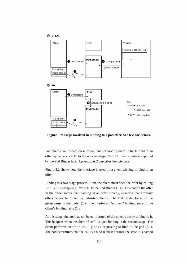
Open (name)
Client
1 2
3
Pod Binder
Trader
Lookup (name)
name: (PodID, offer_st)
. . .
. . .
IDC call
ntsc_call_pod
Key:
OPEN:
Client
3
Pod Binder
Pod
FIX:2
1
PCB bindings:
PodID, offer_st. . .. . .
(PodID, offer_st)
PCB bindings:
PodID, bind_st. . .. . .
SetState (bid, bind_st)
1 BindReq(bid)
2
direct update
Pod
Figure 5.2: Steps involved in binding to a pod offer. See text for details.
Pod clients can inspect these offers, but not modify them. Clients bind to an
offer by name via IDC to the non-privileged PodBinder interface exported
by the Pod Binder task. Appendix A.2 describes the interface.
Figure 5.2 shows how the interface is used by a client wishing to bind to an
offer.
Binding is a two-stage process. First, the client must open the offer by calling
PodBinder$Open() via IDC to the Pod Binder (1.1). This names the offer
in the trader rather than passing in an offer directly, ensuring that arbitrary
offers cannot be forged by untrusted clients. The Pod Binder looks up the
given name in the trader (1.2), then writes an “unfixed” binding entry to the
client’s binding table (1.3).
At this stage, the pod has not been informed of the client’s desire to bind to it.
This happens when the client “fixes” its open binding in the second stage. The
client performs an ntsc call pod() requesting to bind to the pod (2.1).
The pod determines that the call is a bind request because the state it is passed
117

in is the offer st it returned earlier. The current implementation distinguishes
offer st pointers by setting their bottom bit, however should this technique not
be possible on the particular architecture under consideration other techniques
are available; for example the both bind and offer state records could consist of
a common initial portion holding a flag whose value specifies whether this is
normal call or a bind request. The pod may reject the bind request and return
an error code. Should the pod accept, it allocates and initialises any per-client
state it needs (bind st), then calls PodBinder$SetState() via IDC (2.2)
which updates the client’s binding table to hold the new bind st pointer (2.3).
The client’s binding table is mapped read-only to the client to prevent it insert-
ing forged bindings into the table. Only the Pod Binder task is privileged to
update client binding tables.
The advantage of this two-stage binding scheme is that the pod is tunnelled
into by the client to perform the majority of the work of the bind: this means
the pod’s bind request handler runs in the same environment as future calls will
do, so it can fully vet the client. Also, per-client state can be allocated either
from the client’s own heap if it does not need to be trusted, or in a pod-local
heap with suitable protection if it must be trusted. Another advantage is that
the bind happens using client CPU resource guarantees; should binding be an
expensive operation then it is correctly accounted.
Note that the first call the client makes to the pod completes the binding pro-
cess, but is otherwise ignored.
5.3.2 Calling a pod
Having opened and fixed an offer to get a binding id, the client may now make
calls on this binding by tunnelling a thread into the pod. This section describes
how this tunnelling behaviour is achieved on the Intel processor architecture.
Similar implementation tactics are likely to work on other CPU architectures
since no special features of the Intel architecture are assumed, but CPUs with
a software-loadable TLB would most likely permit a simpler implementation.
Triggering the switch
So that pods maintain their integrity, clients may only call them at their pub-
licly advertised entry point. This can be enforced in one of two ways. In both
118

cases, pod code must not be directly executable in the client’s protection do-
main (otherwise the client could simply jump into the pod at any point of its
choosing). This means that client will take a page fault if they try to execute
pod code directly.
The first way of triggering a switch is to use these page faults. For example,
Escort (the version of Scout with memory protection) looks up the faulting
address in an in-kernel table and if it is a known entry point it performs a
protection switch. This means that a protected call in Escort is no different
from a normal procedure call which has a certain pleasing simplicity about it,
however it does mean that all page faults need to be tested to determine whether
a protected module call is being attempted. This slows every page fault, even
if they are unrelated to cross-pdom calls.
The alternative, used by Expert, is to use a system call implemented using a
software interrupt to a handler which performs the minimal checks needed and
changes protection domain. This has the advantage that on most processor
architectures, taking a software interrupt is faster than a page fault since the
page tables do not need to be walked. For example, a system call on the test
machine takes 280 cycles on average while a page fault takes 440 cycles.5 It
also avoids polluting the fast-path of the page fault handler.
Expert introduces the ntsc call pod() system call, which takes as argu-
ments a binding id, a method number, and an opaque pointer to the method
arguments.
Pre-switch checks
The kernel implementation of ntsc call pod() checks that the binding id
is within the binding table in the client’s PCB, and that there is room on the
boost pdom stack for another pdom; these are the only tests needed, and both
are simple compares of a value against a limit.
Invalid (i.e. unallocated) binding ids are dealt with by having the Pod Binder
pre-allocate all possible binding ids to point to a stub which returns an error
code, thus creating a fast path by eliminating such error checking from the
in-kernel code. This is a specific use of the following general optimisation
technique: all inputs to a function should be valid or easy to validate, aiming
5In both cases, the measured value is the time taken to switch from user mode to a C envi-
ronment in kernel mode, then restore and switch back to user mode.
119

to reduce the number of special cases or error recovery code needed in the
function itself.
The binding id is used to index into the client’s binding table to recover the pod
id to be called, and the state pointer to be passed in (either offer state or binding
state). The pod id is used to index into an in-kernel pod table to discover the
pod’s entry point and pdom.
The entire code to performs these checks, switch protection domain, and call
the pod entry address comes to just 44 instructions.
Argument marshaling
There is no marshaling needed when a client tunnels into a pod – types are
represented as defined by the native procedure call standard, either on the stack
or in registers as appropriate. For the Intel x86 architecture, they are passed on
the client’s stack frame.
Large arguments are passed by reference in pre-negotiated external buffers. For
example, packet data are passed using pod I/O channels; this is covered in more
detail in Section 5.3.4.
Pointers passed into a pod should not be blindly dereferenced by the pod; oth-
erwise a malicious client might be able to read memory it does not normally
have access to by using a pod to perform the access on its behalf. Similarly,
pods should not write through pointers passed to them without first checking
they point to reasonable areas. Pointers to large arguments like packets can
be checked to ensure that they lie within address ranges pre-negotiated at bind
time. For other pointers, the pod should manually walk the canonical protec-
tion tables to discover the rights the client has on the memory the pointer refers
to, and reject the call if the rights are insufficient.
There are two approaches to verifying the common case of arguments which
are pointers into the client’s stack. If the client is reasonably trusted, then
merely checking the pointer argument against the stack pointer is enough. This
gives some protection against bugs, but because a malicious client can set the
stack pointer to an arbitrary value before calling a pod, a paranoid pod would
have to perform the full pointer check described above.
An alternative to passing pointers is to pass small integers. The pod can use
them to directly index into a per-client table to retrieve an appropriate state
120

pointer. The small integers can easily be range-checked to avoid illegal ac-
cesses, and since the table is per-client undesirable snooping of another client’s
data is avoided. The use of small integers as file descriptors in Unix is an
example of this technique.
Pdom stack manipulation
The last thing the kernel does before calling the pod is to push the pod’s pdom
onto the pdom stack, thus making available the rights granted by that pdom the
next time a page fault occurs.
Expert, like Nemesis, requires a software loadable TLB, and emulates one on
architectures without native support. This is done by maintaining a minimal
set of hardware page table entries which shadow a definitive set of protection
rights held by a pdom. When a page fault occurs, the kernel looks up the defini-
tive rights in the pdom and inserts an appropriate entry into the hardware page
tables. When a protection switch occurs, these extra page table entries are re-
moved and the TLB is flushed. The next time an access is attempted which
is not in the page tables, the page fault handler consults the new pdom’s ac-
cess rights to determine whether a hardware page table entry should be added,
or whether a genuine access violation has occurred. Most of the time, the
code or data being accessed is globally accessible and so the number of page
faults taken is low. This scheme’s efficiency is further improved by noting each
pdom’s working set when it is de-activated, and speculatively re-inserting those
mappings into the page table when switching back to that pdom.
Expert modifies this scheme to use a stack of pdoms as the canonical protection
information, rather than just a single pdom. When a page fault occurs, the
access is allowed if any pdom on the current stack would allow it.
The ntsc call pod() system call also needs to mark the current contents of
the hardware page table as non-authoritative since the pdom stack has changed,
otherwise clients can leave low privilege rights in the page table which are now
inappropriate for a higher privileged pod.
When the pod call returns the boost pdom is popped off the pdom stack, any
extra page table entries which were added are removed, and the TLB is flushed.
This ensures that pages which were previously accessible while running in the
pod are no longer available. Another system call, ntsc popadom(), is used
to pop the topmost pdom off the stack, and is called before returning from the
121

pod.
To avoid each pod ending with ntsc popadom(), ntsc call pod() ac-
tually calls a wrapper function rather than calling the pod directly. This wrapper
calls the pod’s entry point, then pops the pod’s boost pdom, before finally re-
turning from the original ntsc call pod() system call to the pod’s caller.
This scheme is very similar to the way signals are handled in Unix: a special
sigreturn() system call exists to resume the main user program once its
signal handler returns, and the kernel arranges that this system call is made by
modifying the return address of an extra procedure call record it places on the
user stack.
5.3.3 Pod environment
This section describes how and why the runtime environment is modified when
a thread runs within a pod.
Activations and thread scheduling
Normally when the kernel grants the CPU to a task, it is activated as described
in Section 3.2. This allows the efficient implementation of user-level thread
schedulers by making it easy for the scheduler to be up-called regularly: the
task’s activation vector is set to the user-level scheduler’s entry point, thus al-
lowing user control over which thread to resume when receiving the CPU. Crit-
ical regions in the user-level thread scheduler are implemented by disabling ac-
tivations during these critical regions by setting a flag in the DCB. This flag is
checked by the kernel when activating a DCB to determine whether to resume
or activate the DCB.
However, allowing a thread to tunnel into a pod breaks the implicit assumption
in this scheme: it is no longer the case that all threads share the same protection
rights on memory. This means each thread context slot must also store the
pdom stack in force for that thread, and thread to thread context switches would
need kernel intervention if a protection switch is also involved.
Other operating systems which allowed tunnelling such as Mach or Spring did
not feature activations, and thus the kernel was always involved in switching
between threads. What are the choices available to Expert?
122

1. Allow activations. If activations are allowed while some threads are
within pods, then the kernel must be involved in thread switches. Also,
the context slots could not be stored in user-writable memory, since oth-
erwise it would be possible to modify an untrusted thread’s saved pdom
stack and resume the thread to bypass the protection scheme. Context
slots cannot even be kept in read-only memory, since this would let an
untrusted thread monitor the context slot of a tunnelled thread and thus
discover data held in the thread’s registers which should be protected.
Therefore the context slots would need to reside in kernel memory, but
this would complicate the kernel by needing a dynamic memory alloca-
tor.
Another problem is that if the context slots are writable and managed by
the user-level scheduler, then it can perform a lightweight setjmp() to
save a thread’s state when it blocks. This is cheaper than saving all the
thread’s state since only the callee-saves registers need to be written to
the context slot; the caller-saves registers will have already been saved
on the thread’s stack by the compiler as part of its implementation of the
procedure call standard. The kernel is only needed to resume a thread if
the kernel preempted it. If, however, the context slots are not writable
by the user-level thread scheduler then the kernel is needed to resume all
threads, regardless of how they lost the CPU.
If activations were allowed, which activation handler should the kernel
call when activating a tunnelled thread? Certainly not the client’s, be-
cause if the kernel called the client’s activation handler then it would be
running untrusted client code using the pod’s boost pdom, which would
violate the protection scheme. Alternatively, the kernel might run an ac-
tivation handler specified by the pod, allowing it to schedule the threads
currently within itself in any manner it chooses. While this initially
sounds attractive, note that the pod might not run the thread from the
path which was granted the CPU. This destroys the direct connection be-
tween a path’s CPU guarantee and its rate of progress, and defeats the
purpose of this work.
2. Disable activations. Activations could be disabled when a thread tun-
nels into a pod: threads would always be resumed if preempted while
running within a pod.
3. Single threaded. A new schedulable entity could be introduced, which
does not normally run in a multi-threaded manner, and thus it would not
need activating either to regularly re-enter a scheduler.
123

Expert uses a combination of these last two: paths are intended to be single
threaded, and this is enforced by having ntsc call pod() disable acti-
vations while a call is in progress. The ntsc popadom() system call re-
enables the usual activation / resume scheme once there is only one pdom left
on the pdom stack, i.e. control has returned to the base pdom.
This allows both paths and tasks to call pods. Applications requiring a full-
featured multi-threaded environment can be implemented using tasks. The ad-
vantage of allowing tasks to call pods is that control and initialisation of pods
may be done by tasks. Paths can then be used as lightweight single-threaded
I/O threads, typically collecting an input packet, processing it through one or
more pods before queueing the result for output. This is much like the Scout
model of a path, except that because Expert paths are preemptively scheduled
by the kernel, they may embark on more CPU-intensive processing without af-
fecting the responsiveness of the system (Scout copes with this by having the
programmer add explicit yield points to the code).
Note that if a thread which has tunnelled into a pod blocks, the entire task or
path owning the thread is blocked. This means that pods may use IDC to call
other tasks, but such calls will block all threads in the caller task or path for the
duration of the call. Pods “capture” threads which tunnel into them: the caller is
no longer in control of its own thread. This is required for security, but can lead
to unintended consequences in multi-threaded tasks: user-level threads will not
be scheduled in a timely manner, event delivery and timeouts will be delayed,
and incoming IDC calls will not be processed. This leads to the potential for
deadlock if a task tunnels into a pod which ultimately makes an IDC call back
to the original task. For all these reasons, single-threaded paths are the most
suitable entity to call into pods. Tasks should limit themselves to calling pod
methods which are short-running and non-blocking. If a task needs to perform
many long-running or blocking calls, this is an indication that a path is more
appropriate way of capturing the control flow.
Locks
Taking out locks in pods can also cause an effect similar to priority inversion:
because paths tunnelling into a pod bring their resource guarantees with them,
if the pod serialises their execution then a path with a large CPU guarantee can
become rate-limited by a path with a lower CPU guarantee. Several solutions
to this problem exist:
124

• Paths running in a locked critical region can inherit the highest CPU
guarantee of all blocked paths. This is analogous to priority inheritance
in a priority-based system [Lampson80].
• [Menage00, Section 5.6.2] advocates having servers underwrite criti-
cal sections, providing spare CPU cycles to ensure a minimum rate of
progress through critical sections. Menage also suggests that servers
could simply reject calls from principals with insufficient CPU guaran-
tees.
• [Harris01, Section 7.6.3] suggests temporary CPU cycle loaning, where
blocked paths donate their cycles to the path currently running in the
critical region, thus “pushing” it through. The pushed path later repays
the loaned cycles once it has exited the critical section.
• Non-blocking data structures such as those proposed by [Greenwald99]
can be used.
• Critical regions can be kept to a minimum number and length. This prag-
matic solution is no defence against malicious paths which might pro-
ceed arbitrarily slowly, however it works well in most situations. A pod
written in this style will typically prepare all the details needed before
taking out a lock and making the update, thus expunging all superfluous
code from the critical region. This is the approach taken by Expert.
As with any case of abnormal termination, if any locks are held then the data
structures protected by the locks may be in an inconsistent state. Standard so-
lutions to this include rolling back changes, working on shadow copies before
committing, forced failure of the whole component, or using lock-free data
structures.
Stack switching
Conventional wisdom says that each protection domain should have its own
stack. This would imply that each pod would need to switch to a private stack
for the duration of its processing. This is the approach taken by Spring:6 each
server protection domain has a pool of threads, each of which includes a pre-
allocated stack. Execution takes place in the context of a “shuttle” which con-
6Spring was discussed in Section 2.3.3.
125

trols the scheduling and accounting of the processing regardless of which pro-
tection domain it occurs within.
The reason for this is so that other threads which have not tunnelled cannot spy
on the tunnelled thread’s stack and so snoop sensitive intermediate data. More
importantly, if the stack is writable by other threads which have not tunnelled,
then one could re-write a return address in a stack frame of the tunnelled thread
and so divert it to run malicious code.
There are several advantages to not switching stacks on protection switch. The
performance is better, since arguments can be passed on it directly without
needing to be copied across, and stack pages are likely to be already in the
cache and already have a valid TLB entry. Also memory usage is reduced, by
requiring only T stacks rather than T ×P for T threads traversing P pods. This
could be mitigated by only allocating N < T stacks and sharing them on the
assumption that it is highly unlikely that all threads will simultaneously tunnel
into the same pod.
There is also the question of when stacks should be allocated: the logical time is
during the bind phase, however the allocation code needs to recognise multiple
binds from the same client and re-use the same stack for each.
Another alternative would be to use a single stack, and merely change the ac-
cess rights to flip it into the pdom being tunnelled into. This has an associated
performance cost, since the stack pages would need to have their entries in
both the client and pod pdoms updated to reflect the change in permissions.
The hardware page tables and TLB would not need updating however, because
as both the stack permissions and current pdom have changed together the ef-
fective access rights remain unmodified – the pdom updates are needed in case
the pod is preempted and later resumed.
The ntsc call pod() system call does not switch stacks, but instead uses
the caller’s stack while running inside a pod. The stack access rights are un-
modified. This is safe because since activations are disabled no other thread
can read or write the stack if the pod is preempted. The scheme has the twin
merits of being simple and fast.
In any case, a paranoid pod can manually perform a stack switch as its first
action, since the binding state passed in by the kernel can contain a pointer to
a pre-prepared stack. If the kernel were to always switch stacks, a pod would
no longer have the choice of whether to run on the same stack as its caller or
126

not. Instead, Expert allows a range of security policies to be used depending
on how trusted the code running on a particular system is.
One remaining concern is that the pod could exhaust the available stack space.
A malicious client could use this to force the pod to take an unexpected memory
fault, which could compromise the security of the system. While this kind of
attack is not expected (given that the memory protection in Expert is mainly a
debugging and system partitioning tool rather than a security device), it can be
protected against by having pods check the stack pointer on entry and return
immediately if there is insufficient stack space remaining.
Pervasives
Both Nemesis and Expert keep a per-thread list of pointers to commonly used
(i.e. pervasive) objects. This pervasives record includes pointers to the current
threads package, an events package for synchronisation, a default heap alloca-
tor, a virtual processor interface, standard input, output and error I/O streams,
and various library entry points (e.g. for libc).
These objects form part of the processing environment of a thread, and must be
vetted when a thread tunnels into a pod. For example, if a pod calls printf()
then this will ultimately translate into method calls on the standard output ob-
ject in the pervasives record. Should the pod fail to override this object, then it
risks losing control to untrusted user code. A similar situation arises for all the
other members of the pervasives record.
Therefore, one of the first things a pod should do is to change the current per-
vasives to point to its own, trusted set. Typically, this will include known-good
I/O streams for diagnostic output, a trusted events package, and a private heap
manager.
How much is shared with the untrusted caller application is up to the pod. For
example if the pod wishes to also allocate state in the caller’s heap then the
caller and the pod must agree on the format of the heap’s state record. The
pod can then create its own trusted heap manager using system-wide library
code and the state pointer for the untrusted client heap. This is feasible because
paths are encouraged to use the system-wide libraries, so allowing interoper-
ability with pods. The disadvantage is that paths have less flexibility over the
implementation of their data structures if they are forced to use standard li-
braries. This is another reason why paths are kept separate from tasks: paths
127

run in a stricter and less flexible environment, and benefit by being able to cross
protection boundaries efficiently.
The same issues surrounding shared heaps also apply to sharing event count and
sequencer primitives. In this case, the motivation is to allow a multi-threaded
task or path the ability to run single threaded while within a pod. The pod
creates at bind time a minimal events package which understands the standard
layout of a system-provided events package, but blocks the entire task (or path)
rather than yielding to another thread should the current thread of execution
block. This is needed to allow multi-threaded tasks to call pods, but causes
the task to lose control over the scheduling of its threads once one of them
tunnels into a pod. As previously discussed in Section 5.3.3, this is useful for
the initialisation and configuring of pods, but otherwise tasks are not expected
to make frequent calls to pods; single-threaded paths are more suited to making
frequent pod calls.
While the overhead involved in scrubbing the runtime environment on each
call might seem high, the new pervasives records can be prepared at the bind
stage, so that a single memory write is all which is required to enable it while
processing a call. Incidentally, such scrubbing would be needed in any system
supporting tunnelling; by making it explicit Expert gives the pod control over
how much of the client it wishes to trust, allowing the security policy to range
from fully trusting the client pervasives (insecure), to building a complete set
of fresh pervasives from scratch (secure).
5.3.4 Pod I/O channels
The movement of packetised data is expected to be a major feature of applica-
tions running on a NEOS. This section describes how pod calls can be used to
transfer such data between a client protection domain and a pod. This is useful
for three reasons:
1. Pods are most likely to be on the data path, and in a NEOS this means
the packet processing path. It is also desirable to link pods together via
I/O interfaces to form packet processing chains.
2. A uniform I/O API can be used, regardless of whether the packet data is
carried between two tasks using an I/O channel or within a path via pod
calls.
128

Key: scheduling principalcode/pdomdata flow
path
pod 1 pod 2
kernel
path
pod
(a) Pod on a stick (b) Pod consumer
Figure 5.3: Pod I/O scenarios.
3. The I/O API allows multiple packets to be batched together before flush-
ing them further down the pipeline, which amortises the cost of switch-
ing protection domain. While cost of ntsc call pod() is far lower
than using a full I/O channel,7 the costs are large enough to be worth
spreading over multiple packets.
The two basic scenarios when a path may want to call a pod to process packets
are shown in Figure 5.3.
Figure 5.3(a) shows the “pod on a stick” scenario: here the data flow is from
the path, through the pod, then back to the same path’s protection domain for
further processing. Figure 5.3(b) shows the “pod consumer” scenario: in this
case data flows from the path’s protection domain and is disposed of by one or
more pod(s). The pod is responsible for handing the data on to another pod, or
ultimately to the network device driver in the kernel for transmission.
An example of the “pod on a stick” scenario would be a shared packet cache.
A concrete example of this might occur in a network-based personal video
recorder implementation, where each connected client (or class of client) is
serviced by a dedicated path. The shared cache would store a moving window
of recently streamed video packets so that any of the per-client paths can seek
backwards in the stream, without each needing to keep a private cache. To en-
sure paths see a consistent cache state it would be implemented as a pod, and
paths call the pod to write new data to it or read from it. Perhaps some paths
represent users who have paid for certain video streams, and so other paths
7see Table 5.1
129

should not be able to read packets from those streams from the cache. To en-
force this, the cache would need its own protection domain. If the cached data
does not need to be segregated then the paths could use lock-free algorithms to
access the cached data and so avoid the need to call a pod.
The second of these scenarios matches the structure of a layered network stack:
each layer performs its processing, then hands the packet on to the layer below
it for further processing. For example, if the lower layers of a protocol stack
need to be trusted, then they could be implemented as a pod which paths tun-
nel into to transmit data. The ring-like manner in which recursive pod calls
encapsulate each other (while mainly a performance trade-off) is suitable for
a system where successively lower layers of a protocol stack are more trusted
than those above them; this is a typical arrangement in many kernel-based sys-
tems, where the user-kernel boundary induces a coarse-grained two-level trust
boundary between untrusted protocols implemented in user-space (e.g. HTTP),
and trusted implementations residing within the kernel (e.g. TCP).
Implementation
The implementation of pod I/O channels in Expert is inspired by I/O chan-
nels in Nemesis, and similarly has two FIFOs which are used to exchange
iorecs describing buffers within a pre-negotiated data area. However the
implementation can be more efficient for two reasons. Firstly, because of the
single-threaded nature of paths these pod I/O channels will never be accessed
concurrently. This means concurrency controls can be dispensed with, leading
to a more efficient implementation. Secondly, the client remains in control of
the batching behaviour by explicitly calling IO$Flush() when it is prepared
to push data further along the processing path. The IO$Flush() method per-
forms an ntsc call pod() to transfer control to the pod to allow it to drain
queued packets from the I/O channel. Section 5.4.2 presents results showing
how the batch size can affect the performance of a pod I/O channel by an order
of magnitude, so being able to control it to trade latency against efficiency is
crucial.
The relaxed concurrency requirements means simple integers are used to con-
trol access to the FIFOs – full inter-domain event counts are not needed. Each
FIFO has two counters associated with it: one which records how many pack-
ets have been inserted into the FIFO (the write counter), and one which records
how many have been read (the read counter). They are used to determine
130

direction of data transferProducer(client)
Consumer(pod)
owrord
PutPkt GetPkt
rrdrwr
PutPktGetPkt
outbound FIFO
return FIFO
Producer split-FIFO:
owr
rrd
outboundFIFO
storage
Consumer split-FIFO:
rwr
ord
returnFIFO
storage
Figure 5.4: FIFO and counter ownership in a pod I/O channel.
whether there is data to be read or space for writing, and if so, which FIFO slot
should be read or written next. Their purpose is identical to the inter-domain
event counts used to implement Nemesis I/O channels.
The difference is that Expert merges the implementations of the two FIFOs.
This is possible because they are always used in pairs, and the FIFOs share
the same memory access requirements as the counters. For both FIFOs each
counter is writable by either the producer or the consumer, but not both. Fig-
ure 5.4 shows which FIFOs and counters are owned (i.e. writable) by the pro-
ducer (client) and consumer (pod): the outbound FIFO needs to be writable
by the producer, along with its write counter owr. The read counter for the
outbound FIFO ord needs to be read-only by the producer, since it is updated
by the consumer. The return FIFO needs the mirror image of these rights: the
FIFO should be writable by the consumer, with its write counter rwr writable
by the consumer but read-only to the producer. The read counter ord should
be read-only to the consumer, and writable by the producer.
By gathering the client-writable FIFO and the two client-writable counters into
a single block of memory, Expert ensures that all have the same access rights,
and all are close together to ensure they are cache-efficient. Similarly, the pod-
writable FIFO and the other two pod-writable counters are gathered together
into another “split-FIFO”. These two split-FIFOs are only usable as a pair, but
this is their intended purpose. By contrast, Nemesis I/O channels implement
each FIFO using event counts, which take longer to increment or test than the
single memory words used as counters by Expert.
131

In order to create such a pod-based I/O channel, the pod allocates a data area on
the client’s heap (so that both the client and the pod have write access to it). The
pod then allocates its split-FIFO on a heap which the client has only read access
to. The pod retains write access to the return split-FIFO and the associated
counters. Finally it allocates the client’s split-FIFO on the client’s own heap,
so the client may write to it. The pod returns a descriptor containing: pointers
to the data area and the two split-FIFOs; the binding id and method number to
be used to flush data onwards; and the FIFO depth. From this descriptor, the
client then creates an instance of the I/O interface. The pod does the same, but
swaps the split-FIFOs over in its copy of the descriptor, thus ensuring it reads
what the client writes and vice versa.
Note that because the pod is granted a superset of the client’s access rights to
memory, the pod has write access to the client’s split-FIFO. This is unimpor-
tant, since the client is already assumed to trust the pod.
5.4 Results
5.4.1 Micro-benchmarks
Micro-benchmarking is concerned with measuring the performance of individ-
ual small components of a system, leading to the (fallacious) assumption that
knowing the performance characteristics of the components allow some mea-
sure of the complete system behaviour to be deduced. This is not the case for a
number of reasons [Bershad92]:
• Measuring an operation in isolation does not accurately reflect its perfor-
mance when used as part of a real system, as it does not consider cache
effects.
• Micro-benchmarks give no indication of how often a benchmarked oper-
ation is performed. Amdahl’s Law says that:
Speedupoverall =1
(1 − Fractionenhanced) + Fractionenhanced
Speedupenhanced
This means that unless the operation being benchmarked occurs fre-
quently (i.e. Fractionenhanced is large), its cost is mostly irrelevant.
• The results are impossible to compare, both across time (wait another
132

OS proc call system call CALLPRIV pod call IPC
Linux (hot) 7 340 n/a n/a 3500
Linux (cold) 44 760 n/a n/a 9100
Expert (hot) 7 280 260 2900 19000
Expert (cold) 44 460 390 5000 21000
Table 5.1: Cycles taken for different calls with hot and cold caches.
18 months and performance will double), and across architectures (what
takes 20 cycles on a CISC CPU may take 30 cycles on a RISC CPU).
Despite these obvious pitfalls, micro-benchmarks can be used to give a rough
idea of the cost of various primitives. This section presents micro-benchmark
results comparing the cost of various protection switching schemes under Linux
2.2.16 and Expert. A proper evaluation of a moderately complex system built
using the primitives presented here is discussed in the next chapter.
As in previous experiments, fox is used as the test platform. It is an Intel
Pentium Pro running at 200MHz, with 32MB RAM, 256KB L2 and a split L1
cache: 8KB I / 8KB D.
Table 5.1 shows how many cycles it takes to execute a variety of different types
of call. The cache hot number is given first, then the cold cache. The cold
cache number is more meaningful, since calls which span protection domains
are likely to be made infrequently and thus without already being in the cache.
The tests are as follows: “proc call” is a C-level procedure call to a func-
tion which takes no arguments and returns no value. The “system call” is
getpid() on Linux, and ntsc send() on Expert (a comparable minimal
system call, since getting the current process ID does not require a kernel trap).
The “CALLPRIV” test is a trap to kernel, null procedure call, then return back
to user-space. The “pod call” is a switch from the untrusted client protection
domain to a pod environment with scrubbed pervasives, and back again. The
“IPC” test sends 4 bytes to another protection domain, and waits for a 4 byte re-
sponse. It does this using pipes under Linux, and a full event-count I/O channel
under Expert.
For hot cache experiments, the result quoted is the average of 100,000 calls.
The cold cache results are an exponentially weighted moving average of 40
calls, with activity in between each timed call to ensure the cache is filled
133

with unrelated code and data. For Linux, this consists of forking two cat
processes and blocking for one second; the cat processes pull data through
the data cache, and because they are run as part of a shell script, much code is
executed thus clearing the instruction cache. For Expert, the caches are cleared
by listing a large traded namespace and blocking for one second. The results
from the procedure call experiments were used as a sanity check to verify that
the results matched across Linux and Expert.
Unsurprisingly, a procedure call takes the same amount of time on both op-
erating systems. A system call is marginally faster on Expert, but full IPC is
much slower. One possible reason for such slow IPC on Expert is that I/O
channels offer a richer feature set, including using scatter-gather lists, blocking
with timeouts, and preserving message boundaries, none of which were used
with pipes under Linux.
More interestingly, the table shows that an Expert pod call is between 17% and
45% faster than IPC on Linux. It also has better cache behaviour than IPC on
Linux, as can be seen from the cold cache numbers. If the pod trapped into is
configured to switch to a private stack, the cost rises to 4100 / 6300 cycles for
warm and cold caches respectively. Instrumenting the protection fault handler
shows that this extra cost arises because twice as many faults are taken when
the stack needs to be switched.
In summary, I/O using IPC on Expert is 85% slower than I/O using pods. The
next section presents further evidence for this.
5.4.2 Pod I/O performance
This section profiles the performance of the pod I/O channel mechanism which
is constructed over the basic ntsc call pod() system call.
In these experiments, fox is again the machine under test. A test client is run
which establishes a pod I/O channel to a pod in another protection domain. The
client sends 100,000 sequence-numbered packets to the pod, which verifies
each sequence number before returning the packets unmodified back to the
client. The client measures the number of cycles taken to transfer and retrieve
all 100,000 packets, and divides to get an average number of cycles expended
per packet. These are the quoted results in each case. The client is written to
queue as many packets as possible before flushing them.
134

In all cases, the cache will be hot since the I/O operations are performed in a
tight loop. This is reasonable because it reflects how the API is used in real
applications: typically, they repeatedly call GetPkt(), process the data, then
call PutPkt() to pass it on. Once an I/O channel fills, the application calls
IO$Flush() thus yielding to allow the next stage on the path to enter its
processing loop.
Comparison against other I/O schemes
With a 32 packet deep pod I/O channel, Expert takes 580 cycles per packet. By
comparison, a Nemesis I/O channel of the same depth between two protection
domains and running the same I/O benchmark takes 6900 cycles per packet.
Linux running a port of the I/O API using two pipes (one for each direction),
and the readv() and writev() system calls for scatter / gather I/O takes
7300 cycles per packet, however with Linux it is impossible to control the
batching so it may well context switch for each packet. A Linux implemen-
tation using SysV shared memory regions may improve the performance by
allowing better control over the synchronisation of the producer and consumer
process, as well as removing copying overheads. However, note that in all tests
the packets were only four bytes long (the sequence number), so copy-related
overheads are minimal thus minimising any pipe-related penalty Linux might
incur. Nemesis and Expert pod I/O channels are both zero-copy, so the payload
size is not a factor.
Effect of batch size
To discover how much of an effect the batch size has, I repeated the Expert pod
I/O experiment with a range of I/O channel depths ranging from one packet (i.e.
no queueing) to 512 packets. Figure 5.5 shows how many cycles per packet are
taken to complete the previous experiment for I/O channel depths increasing in
powers of two.
Even when Expert cannot batch because the channel depth is limited to one
packet, at 5500 cycles Expert’s pod I/O channels are still faster than both
Nemesis with 32-deep channels and Linux. It can also be seen that at a depth
of 32 packets, most of the efficiency gains have been achieved, and deeper
channels will merely increase latency and waste memory.
135

100
1000
10000
1 4 16 64 256
Cos
t per
pac
ket (
cycl
es)
Batch size (number of packets)
Figure 5.5: Pod I/O depth vs. cost.
5.5 Summary
This chapter has argued that allowing threads to tunnel between protection do-
mains is useful for a variety of reasons. By using only one resource princi-
pal across multiple protection domains, resource allocation and scheduling is
simplified. Switching between tasks requires a scheduler pass which can be
avoided by tunnelling, allowing finer-grained de-composition of system func-
tions.
Expert allows the application programmer a very wide variety of ways of man-
aging code and threads. Tasks are used for traditional batch-mode processing
where little I/O is required, for example system services. Paths have a more
restrictive run-time environment but benefit from being able to make calls into
protected modules (pods). Tasks are used to implement and call active servers,
paths tunnel into passive pods.
Pods use an explicit binding phase to perform vetting and to setup any per-path
state needed. The kernel makes it easy for a pod to access this per-path state by
passing it as a parameter to all pod calls. Pods are more privileged than their
callers: these concentric rings of protection map naturally onto protocol stacks,
136

and allow efficient tunnelling. Pods can choose their security policy: if a pod
trusts its client, it may use the client’s environment without limit as if it were
the client. If not, it may replace its inherited environment with a secure one,
including the option of performing a stack switch.
Pods can be considered a generalised form of SysV STREAMS [Sun95], where
there is no restriction on the interface offered by a pod. Thus, pods may be used
to implement stackable components, such as STREAMS modules or protocol
boosters [Feldmeier98].
Packet I/O to pods is implemented behind the same API as packet I/O to tasks,
bringing the same benefits: explicit control over batching, scatter / gather, and
bind-time checks allowing an uncluttered fast-path.
While the performance of the ntsc call pod() system call and the pod I/O
transport built using it is impressive, the application design flexibility enabled
by pods remains their raison d’etre. The next chapter presents the design of
a complex streaming system supporting different levels of service which is
nevertheless simple to implement by using pods as an integral part of its design.
137

Chapter 6
System evaluation
This chapter presents an extended example which demonstrates how Expert’s
network driver model together with paths allow the CPU and memory resources
used to be scheduled and accounted. This is so that when overloaded the system
may shed load gracefully, thus degrading the externally observed quality of
service in a controlled manner.
A streaming media transcoder is used as the example application run over Ex-
pert. The following section motivates the example, and further describes the
application’s requirements. The next section describes how Expert’s features
are used to implement the application. The final section presents a macroscopic
performance evaluation, and compares an implementation making full use of
Expert’s features against a single-task implementation.
6.1 Motivation
A new radio station, Rock Ireland, wishes to make its broadcasts available via
the Internet so as to reach a sizeable expatriate community. However, Rock
Ireland also needs to recoup the costs of its Internet operation, so it decides
to charge listeners for access to the streaming broadcast. To encourage new
listeners, Rock Ireland wants to provide a low-quality stream for free.
The radio station produces its output as a 44.1KHz stereo 192Kb/s stream of
MPEG-1 Layer III audio (MP3) [Pan93]. The subject of this example is a media
transcoder used to convert this source stream into three quality tiers: gold (the
unmodified stream, which is full-price), silver (44.1KHz stereo, 128Kb/s, at a
138
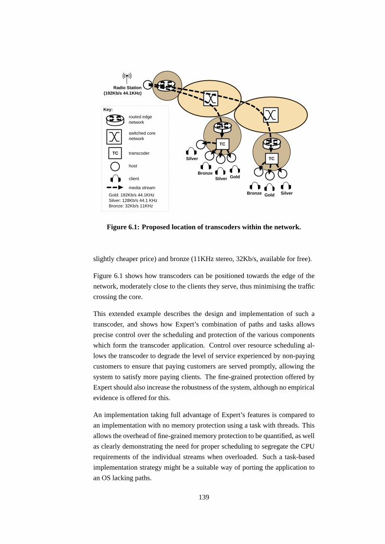
Radio Station(192Kb/s 44.1KHz)
Silver
BronzeSilver Gold
Gold SilverBronze
Key:
TC
routed edgenetwork
switched corenetwork
transcoder
host
client
Gold: 192Kb/s 44.1KHzSilver: 128Kb/s 44.1 KHzBronze: 32Kb/s 11KHz
media stream
TC
TC
Figure 6.1: Proposed location of transcoders within the network.
slightly cheaper price) and bronze (11KHz stereo, 32Kb/s, available for free).
Figure 6.1 shows how transcoders can be positioned towards the edge of the
network, moderately close to the clients they serve, thus minimising the traffic
crossing the core.
This extended example describes the design and implementation of such a
transcoder, and shows how Expert’s combination of paths and tasks allows
precise control over the scheduling and protection of the various components
which form the transcoder application. Control over resource scheduling al-
lows the transcoder to degrade the level of service experienced by non-paying
customers to ensure that paying customers are served promptly, allowing the
system to satisfy more paying clients. The fine-grained protection offered by
Expert should also increase the robustness of the system, although no empirical
evidence is offered for this.
An implementation taking full advantage of Expert’s features is compared to
an implementation with no memory protection using a task with threads. This
allows the overhead of fine-grained memory protection to be quantified, as well
as clearly demonstrating the need for proper scheduling to segregate the CPU
requirements of the individual streams when overloaded. Such a task-based
implementation strategy might be a suitable way of porting the application to
an OS lacking paths.
139

6.1.1 Requirements
Isolation. Since some listeners pay money to listen to the streams, such streams
should be flawless and uninterrupted. The listeners who have paid noth-
ing must make do with whatever spare capacity is available in the sys-
tem.1 Thus the gold, silver and bronze tiers are not only media quality
metrics, but should also reflect the OS resources needed while process-
ing streams of these tiers to ensure that streams from higher tiers are
processed in a timely manner without loss.
This does not establish a route through the network with a guaranteed
quality of service, but it is assumed that the bottleneck resource in this
case is the CPU in the transcoder, not the network: the maximum band-
width emitted is 2.8Mb/s. However, should network resources also need
to be reserved, Expert’s path mechanism provides a natural entity to
which such a bandwidth reservation might be allocated. Alternatively,
if the expected competition in the network is purely local due to other
traffic flows through the transcoder, then the network driver’s transmit
scheduler could be used to rate-limit some flows in order to preserve
capacity for others.
Per-client customisation. To stop non-paying clients from snooping on the
streams which are payed for, gold and silver streams should be encrypted
with a per-client key. While this cannot stop a client from re-broadcasting
a paid-for stream, it foils freeloaders between the transcoder and the
client. Some kind of fingerprinting or digital watermarking scheme may
also be a requirement. However, note that digital watermarks may be
erased, so they do not provide a robust way of preventing re-broadcasting;
using them may be required to meet some contractual obligation.
Per-client audio splicing may be done, for example to target adverts,
offer different disc-jockey “personæ”, or provide personalised news and
weather.
The salient point is that there is a requirement to perform client-specific
non-trivial processing on streams which are paid for, be it encryption,
watermarking or some other customisation. In this example, AES (Ad-
vanced Encryption Standard) is used as the processing performed [FIPS-197].
Protection. The principle of minimum privilege should be applied when de-
1Of course, an unscrupulous radio station may wish to deliberately downgrade the quality of
the bronze stream to provide an incentive for listeners to pay for the higher quality streams.
140

gold
silver
bronze
ENC32Kb/s
192 cache
PCM cache
128 cache
Gold: 1
92Kb/
s,
44.1
KHz ste
reo
Silver
: 128
Kb/s,
44.1
KHz ste
reo
Bronz
e: 3
2Kb/
s,
11KHz s
tere
o
Sourc
e: 1
92Kb/
s,
44.1
KHz ste
reo
ENC128Kb/s
DEC
common-rx
AES
AES
Key:
path
pod
cache
code module
data flow(wider ishigher bitrate)
Figure 6.2: Data flow through the transcoder. See text for description.
signing the application: individual components should only be given ac-
cess to the minimum areas of memory they need to perform their func-
tions. This reduces the probability of accidental or malicious damage,
whether caused by programmer error, or Trojan code. For example, the
encryption keys should only be readable by the encryption modules, so
that key material cannot be leaked from the system. Also, it may be the
case that externally-provided media codecs are used, in which case they
might not be trusted as much as code written in-house.
The transcoder architecture described in the next section uses Expert’s paths
to meet these three requirement. In order to discover their cost and benefit, a
comparison is made with an implementation using a single task, thus foregoing
the desirable isolation and protection properties described above.
6.2 Architecture and implementation
Figure 6.2 shows how packets flow through the transcoder. Arrows depict data
movement and rate; thicker arrows correspond to higher data rates. The mod-
ules implementing the basic functionality are shown in rounded rectangles:
DEC is an MP3 decoder instance, each ENC is an MP3 encoder instance, and
each AES is an instance of an encryption module together with its key mate-
141

rial. The rectangles represent the paths in this system: the common-rx path
handles network receive, decoding, and encoding; the gold paths perform en-
cryption and transmission, one per gold stream; the silver paths do the same
for each silver stream; and the bronze path encodes and transmits one or more
bronze streams. Note that there is a one-to-one mapping between gold and sil-
ver streams and their associated paths, whereas there is a single bronze path to
handle all bronze streams; this diagram shows three streams at each tier. Using
a path per stream allows independent scheduler control over each of the paid-
for streams to meet the isolation requirement, and provides memory protection.
Since bronze streams have no special scheduling needs, they can all be handled
by a single path.
The common-rx path decodes MP3 to PCM (Pulse Code Modulation) samples
then encodes back to MP3 again rather than operating directly in the Fourier
domain (which should be more efficient) for simplicity of implementation.2
The common-rx processing is given its own path because it performs work
which is needed by the other paths: if it does not made adequate progress,
then no other path will. Therefore, making common-rx a separate path allows
its scheduler settings to be appropriately tuned to ensure it is run frequently
enough.
Figure 6.2 also shows how other paths interact with the common-rx path via
its three caches: the 192, PCM, and 128 caches. The caches hold the received
192Kb/s MP3 frames (192 cache), the result of decoding them into PCM sam-
ples (PCM cache), and the result of re-encoding them to 128Kb/s MP3 (128
cache). Each cache is a ring buffer which allows multiple paths to make read
accesses concurrently with write accesses from the common-rx path.
To mediate these concurrent accesses, the caches are implemented as protected
modules (pods) into which paths may tunnel to insert (common-rx) or read (all
other paths) buffers containing either MP3 frames or PCM samples, depending
on the cache in question. These pods are shown by dotted rectangles in the
diagram. The state for the AES modules is held within pods to protect their
key material from the application logic and network stack also running within
the path.
2Source code for both MP3 encoders and decoders is widely available, but Fourier domain
transcoders are less prevalent.
142

write pointer
client Aread pointer
client Bread pointer
09
8
7
6
54
3
2
1
Figure 6.3: Cache data structure. Larger numbers indicate newer entries.
6.2.1 Caches
The caches perform several functions. They decouple the common-rx path
from its clients, while making available the last few packets processed to absorb
jitter in the system. They allow the controlled “spying” of intermediate packets
in the common-rx decode pipeline, without requiring readers to receive every
packet. Ensuring all readers receive all packets would limit the pipeline to
proceeding at the rate of the slowest reader. This would let paths with small
CPU guarantees rate-limit paths with larger guarantees: a classic example of
priority inversion.
Caches maintain a read pointer for each reader, and a current write pointer;
Figure 6.3 shows this arrangement. The read pointer may not overtake the
write pointer – attempting a read when there is no data available blocks the
reader. However, the read pointer may fall so far behind that it is no longer
within the range of the cache. Readers in this situation have their read pointer
set to the oldest valid contents of the cache, and are notified of how many
entries have been skipped over. Writers always write to the write pointer, and
because readers may be left behind, writers need never block.
There are a constant number of buffers in the cache (five in these experiments),
allowing readers to view a fixed amount of history (around 130ms, given 5
MP3 frames of 627 bytes each, arriving at 192Kb/s). Inserting a new buffer
into the cache returns the oldest buffer, which has been evicted. Rather than
storing buffers inline in the cache, (base, length) pairs reference externally
allocated buffers; this delegates the allocation of buffers and their permissions
to the writer. This implies that if the cache read operation returned such pairs
to the caller, the buffer referenced must not be overwritten until the client has
finished using the reference. This violates the design goal of not blocking the
143

writer, so instead the cache read operation copies the contents of the referenced
buffer into a fresh location provided by the caller.
The cache insert and read algorithms are implemented in a pod for a number
of reasons. Concurrency control is simplified by providing a central location
where a lock can be taken out. From a CPU scheduling perspective, the cost of
performing the copy on reading a buffer is accounted to the reader. Also, be-
cause pods are explicitly bound to by clients, the per-client binding can include
the client’s read pointer, speeding access to it.
An alternative implementation would be to place the cache control data struc-
tures in a stretch of memory to which all clients have read/write access, and use
lock-free algorithms to manage concurrent updates to the cache. This would
be an interesting approach; the cache behaviour is complex enough to provide
some entertainment designing such an algorithm, however, all clients would
need to fully trust each other’s cache update algorithms. This is the approach’s
Achilles’ heel: one poorly coded cache client would affect the stability of all
the cache clients.
6.2.2 Buffer allocation and usage
At initialisation time, the common-rx path allocates, binds to, and exports the
three caches. It stocks them with their initial buffers, allocating them writable
by itself, but with no access to the other paths.
The 192 cache is somewhat special: its buffers come from the network stack.
The common-rx path strives to keep three-quarters of the available network-
ing buffers in the driver ready to be received into, but enters the remaining
buffers in the 192 cache to make them visible to gold paths. On packet arrival,
common-rx inserts it into the 192 cache, evicting the oldest buffer; this buffer
is handed back to the device driver to be received into, maintaining the 3:1 split
between network driver and cache.
Eviction is used in a similar manner all the way along the decode-encode
pipeline. For example, the result of decoding is placed into a pre-prepared
buffer and inserted into the PCM cache, returning an evicted buffer which is
noted for decoding into next time around. The same technique is used with the
result of the encoder and the 128 cache.
Because of the nature of the MP3 format, several MP3 frames are needed before
144

any PCM samples are produced. The encoder is similarly bursty, accepting
multiple buffers of samples before producing the next MP3 frame. This is dealt
with by pushing the data (MP3 frame or samples) only as far down the pipeline
as it will go while still generating output, and relying on a continual stream
of incoming frames to drive the whole pipeline forwards. This eliminates the
need to have threads shuffling output from one stage to the next: the pipeline is
driven entirely by network packet arrival events.
6.2.3 Alternative architectures
Having described the path-based architecture above, this section describes two
alternative architectures, neither of which use paths. The first alternative pre-
sented shows how the previously stated requirements can be met using just
tasks, but argues that it would be inefficient. The second alternative shows
how an efficient task-based implementation is possible if the requirements for
protection and isolation are relaxed.
While it would be possible to implement the application purely using paths (for
example for use on Scout or Escort), the path-based version on Expert uses
separately scheduled tasks to implement system services such as the binder
and namespace trader, the serial console driver, the ps2 keyboard driver, Eth-
ernet card initialisation and media detection, network connection setup and
teardown, and an interactive shell from which the system may be configured
and new paths or tasks started. By scheduling these components separately as
tasks, their impact on the transcoder application is bounded. In Scout, such
tasks would either reside in the kernel, or be forced into a path model which
does not closely match their use.
Task-based
The simplest way of implementing the presented path-based architecture on
systems which do not allow tunnelling would be to use a task everywhere the
architecture calls for a path. When gold, silver and bronze tasks need to read
data from the common-rx task, this must be via one of the standard IPC mech-
anisms. In this case, using an I/O channel would be most appropriate since the
buffer could be passed between the protection domains without needing to be
marshaled. Note that the copy out of the cache would still be required to enable
the cache writer to remain non-blocking, but a further copy to marshal between
145

protection domains would be avoided by using an I/O channel.
This design retains the advantages of the path-based architecture: the common-
rx, gold, silver, and bronze components are separately scheduled, and so may
be given appropriate guarantees; and the separate tasks ensure that processing
occurs in distinct protection domains. It is not possible to protect the AES
key material as tightly as in the path architecture, and in the common-rx task
the cache data structures are not protected from the decoder and encoder, but
aside from these minor differences, the task-based architecture is functionally
identical to the path-based one.
However, since the measurements in Section 5.4.2 show that using I/O chan-
nels is approximately a factor of ten slower than tunnelling into a pod, this
architecture would be quite inefficient.
All-in-one
The all-in-one architecture avoids the performance problem with the task-based
architecture by using a single task containing a user-level thread for each path
in the original design. The common-rx, gold, silver and bronze threads all run
within a single protection domain. The task containing these threads is given a
CPU guarantee, but the individual threads are scheduled by a round-robin user
level scheduler and so have no guarantees.
This arrangement means that there is no memory protection between the en-
coder, decoder and AES components. Because the thread scheduler is round-
robin, there is no possibility of isolating the more important common-rx, gold
and silver threads from the bronze thread. This could be achieved by replacing
the thread scheduler with one implementing a more sophisticated algorithm.
This is not done in the all-in-one architecture in order to allow a comparison
between a system providing proper isolation (the path-based one) with one
which does not (the all-in-one design).
Synchronisation between the various threads is done by an implementation of
the cache using a mutex to protect the cache data structures and a condition
variable to allow readers to block and later be woken by inserts. Locking is
still required between the writer and the reader threads since the readers must
see a consistent view of the cache control data structures.
Other than this change in cache synchronisation primitives, the implementation
146

Architecture implemented? protection? isolation?
path-based ✔ ✔ ✔task-based ✘ ✔ ✔all-in-one ✔ ✘ ✘
Table 6.1: Architecture summary.
hornet fox snapper
.
.
gold stream
silver stream
bronze stream
TC
Figure 6.4: Experimental set-up.
of the all-in-one architecture is identical to the path-based implementation, us-
ing threads rather than paths, naturally.
Table 6.1 summarises for each of the discussed architectures whether it has
been implemented, whether it provides memory protection between the ap-
plication’s components, and whether it provides quality of service isolation
between streams.
6.3 Results
This section describes two experiments. The first experiment quantifies the
cost of using paths to achieve proper protection between the components in
the transcoder, by comparing the amount of CPU time needed to achieve loss-
free operation both in the path-based and the all-in-one implementations. The
second experiment quantifies the benefit which scheduling provides, by mon-
itoring the transmission rates of the produced streams for both the path-based
and all-in-one implementations.
Figure 6.4 shows the experimental set-up. In both experiments, hornet (a
Pentium II 300MHz running Linux) is used as the “radio station” source, send-
ing a stream composed of 192 Kb/s MP3 frames. The frame size is variable, but
is typically around 627 bytes. Each frame is encapsulated in a UDP packet and
147

sent to fox. The stream lasts around 146 seconds, and is paced to deliver it in
real-time. Fox is the machine under test, and runs either the path-based or the
all-in-one implementation of the transcoder under Expert. It derives a number
of output streams from the input and sends them to snapper (running Linux),
which discards them. Snapper also runs tcpdump to calculate the bitrates
achieved by each stream from fox.
6.3.1 Cost of protection
In this experiment, fox runs the transcoder application on an otherwise un-
loaded system, and grants the application as much CPU time as it desires: no
CPU limit is in place. The amount of CPU time actually consumed is recorded
by the scheduler as a fraction of the total cycles available to it.
The transcoder application is initially configured to serve one gold, one bronze
and one silver stream. The experiment consists of measuring the CPU time
requirement for both the path-based and the all-in-one designs as additional
silver streams are added. When loss begins to occur because the transcoder ap-
plication would need more CPU time than is available, no more silver streams
are added and the experiment for that architecture is over.
Figure 6.5 shows the measured CPU time required for loss-free operation of
the transcoder. The “path-based” line shows the cost for the path-based ar-
chitecture; the other line shows the cost for the all-in-one architecture. The
path-based version is, as expected, more expensive. Adding protection and
proper scheduling costs between 2% and 5% more than doing without, and the
slightly larger gradient indicates a higher per-stream overhead in the path-based
architecture than in the all-in-one case.
The authors of Escort noted an increase in CPU requirements of between 200
and 400 percent when adding memory protection to Scout [Spatscheck99, Sec-
tion 6]. In their case, this large performance gap may be explained by the fact
that Scout runs without protection, entirely in the CPU’s supervisor mode; by
comparison, the all-in-one design runs within one user protection domain with
occasional traps to supervisor mode to perform network I/O. The architectural
difference between Scout and Escort is thus much greater than the difference
between the all-in-one and the path-based designs: all-in-one and Scout are not
analogous systems.
Table 6.2 shows the fraction of total CPU time spent in each path for a path-
148

0
20
40
60
80
100
0 2 4 6 8 10 12
CP
U r
equi
red
for
loss
-fre
e st
ream
ing
(%ag
e of
mac
hine
)
Number of silver clients
path-basedall-in-one
Figure 6.5: CPU time required to service one gold, one bronze, and a vary-
ing number of silver streams.
Path CPU needed (%) Proportion (%)
common-rx 40.3 45.0
gold 1.6 1.7
silver 1.2 1.2
bronze 46.3 51.8
Total 89.4 100.0
Table 6.2: CPU requirements by path. Totals may not add up due to
rounding.
based transcoder configured with one each of the gold, silver and bronze streams.
The CPU requirement is given both as a fraction of all the cycles available on
the machine, and as a proportion of those spent in the transcoder. The remain-
ing cycles not spent in the transcoder are expended on other system tasks and
in the idle loop, neither of which are recorded in the table above.
The most expensive component in the architecture is the MP3 encoder, which
accounts for the majority of time spent in common-rx and bronze. One possible
reason for this is that when sample rate conversion is performed, the samples
149

must be copied and smoothed to avoid aliasing, and this greatly increases the
CPU cost. It was originally envisaged that the silver streams would be 56Kb/s
at 22KHz, however preliminary work showed that the sample rate conversion
from 44.1KHz down to 22KHz required too much CPU time to fit the pro-
posed experiment on the test machine; transcoding from 44.1KHz at 192Kb/s
to 44.1KHz at 128Kb/s requires no sample rate conversion and is thus cheap
enough for the experiment to be viable.
A similar breakdown of costs for the all-in-one design is not available, because
the CPU usage of the individual threads is not visible to the system-wide sched-
uler and so went unrecorded. The total for all threads was recorded, and came
to 86.7% of the machine.
Because all-in-one is more efficient, it can serve about half as many more silver
streams for the same CPU budget. However, the next experiment shows that
once this limit is exceeded, i.e. when the system becomes overloaded, all-in-
one cannot discriminate between its clients and all streams begin to suffer loss.
A more efficient implementation such as all-in-more merely delays the point at
which overload is reached.
6.3.2 Benefits of isolation
In order to correctly handle overload situations, clients belonging to separate
resource tiers must be distinguished, and their effects isolated from each other.
This can be done by exposing the clients as first-class scheduling entities (paths
in this case), and running them with an appropriate quality of service.
In this experiment, fox services five gold streams, one bronze stream, and an
increasing number of silver streams. The path-based version is configured to
give the common-rx path a 45% share of CPU, the gold and silver paths get
2%, and the bronze path is allocated 15%. All of these shares of CPU time are
allocated over a 100ms time period, and all paths are allowed to use any slack
time in the system. These guarantees are sufficient to meet the CPU needs
for the common-rx, gold and silver paths, but the bronze path ideally needs
approximately 46%. This means that the bronze path will mostly be running
on slack time in the system, i.e. as the number of silver paths increase, the CPU
available to the bronze client will diminish. In this manner, the transcoder’s
administrator has expressed the policy that the bronze path’s performance is
unimportant compared to the common-rx, gold and silver paths.
150

0
20
40
60
80
100
120
140
160
180
200
0 2 4 6 8 10 12 14 16
Rec
eive
d ra
te (
Kb/
s)
Number of silver clients
Gold, path-basedGold, all-in-one
Silver, path-basedSilver, all-in-one
Bronze, all-in-oneBronze, path-based
Figure 6.6: Achieved bitrates for gold, silver, and bronze streams with and
without isolation.
For the all-in-one version of the transcoder, the task is allocated 85ms/100ms
which allows it to monopolise almost all the machine’s resources. It is also
allowed the use of slack time in the system.
The produced streams are captured by snapper which calculates the aver-
age bandwidth achieved by an average gold and silver stream, and the average
bandwidth of the single bronze stream, over the whole experiment. In a loss-
less transcoder, the gold streams should average 192Kb/s, the silver streams
128Kb/s, and the bronze stream 32Kb/s.
Figure 6.6 shows these average bandwidths for the all-in-one case and the path-
based case. Ideally, all the lines should be horizontal and co-incident, which
would indicate that regardless of offered load, the streams continue uninter-
rupted. However, it is clear to see that the gold and silver streams without
isolation (i.e. the all-in-one design) suffer large amounts of loss as the load
increases. In comparison, the gold and silver streams with isolation (i.e. the
path-based version) continue almost unhindered, all the losses being concen-
trated on the bronze stream.
Lack of memory on fox prevented more silver clients from being run to further
151

extend the graph. However, once the CPU requirements of both the gold and
silver clients together reach a level where stealing cycles from the bronze client
is no longer sufficient, the gold and silver streams would begin to experience
loss.
Admission control could be used to reject requests to start new streams, thus
preventing the system becoming overloaded in the first place. While this is
true, the use of admission control is orthogonal to the techniques presented in
this dissertation.
To verify that the scheduler was correctly sharing resources between CPU-
bound tasks as well as the paths this chapter has focused on, a background task
was run during this experiment. It ran in a loop, consuming as much CPU time
as the scheduler allocated it, and occasionally printing how much it consumed.
It was given a best-effort guarantee only. Despite this task’s presence, the paths
ran according to their guarantees and were able to produce the results discussed
above.
6.4 Summary
This chapter used a media transcoder to show how paths can be used in a real
application to:
• map resource consumption onto meaningful entities, so that allocations
can be easily tuned;
• make efficient accesses to shared data;
• tightly control the visibility of sensitive data such as key material.
A path-based implementation of a media transcoder was compared to one im-
plemented within a single task using multiple threads. While the all-in-one
task implementation was 2%-5% more efficient when the system was not heav-
ily loaded, under high load it could not protect the CPU allocations of some
media streams by sacrificing the performance of others.
Despite the presence of a CPU-bound task running alongside the paths, the
scheduler isolated the processing for the paths making up the transcoder appli-
cation from the best-effort CPU-bound task.
152

Chapter 7
Conclusion
This dissertation has presented a number of techniques for managing resources
in a network element. This chapter summarises the work and its conclusions,
and proposes strategies for implementing the core contributions in the context
of more mainstream operating systems. Finally, topics for future study are
proposed.
7.1 Summary
Chapter 2 reviewed prior work establishing the concept of a path as a core OS
abstraction. Particular attention was drawn to the work on Scout, which advo-
cates using paths to encapsulate the processing performed on flows of packets.
The lack of a traditional task-like scheduling class in Scout (and its successor
Escort) was discussed, along with a selection of techniques the Scout develop-
ers have evolved to deal with this deficiency.
The conclusion drawn was that although paths are attractive when processing
packet flows, this is really the only setting when they are useful; tasks remain
necessary for system management and other background activities.
Chapter 2 continued by discussing Resource Containers, work motivated by
the fundamental mismatch between the original task-based design of operating
systems such as Unix, and their use in today’s network-centric environment.
The solution proposed by Resource Containers is to dissociate the scheduled
entity from the process abstraction; effectively creating a path-like entity which
is separately scheduled. Threads in a resource container cannot tunnel into
153

other user-level protection domains however, so their use is limited.
IPC systems specialise in moving control flow and data across protection bound-
aries in a controlled manner. Chapter 2 went on to describe IPC systems, clas-
sifying them into those which block the calling thread and continue the call
within a separately scheduled server, and those which tunnel the calling thread
directly into the server. The Spring and Mach thread tunnelling systems were
described; however both are complicated by the need to handle failures mid-
call, and the baroque debugging and signal environment present in Unix.
Vertically structured systems strive to minimise IPC by making applications
responsible for the majority of their own processing. Both Nemesis and Exo-
kernels were discussed. Driver support for non-self-selecting network devices
was found to be lacking, forcing a separately scheduled device driver onto the
data path to demultiplex received packets and to check and schedule outgoing
packets.
In summary, current OS designs are poorly adapted to performing I/O-driven
processing with quality of service guarantees. Expert is introduced as an OS
which offers a hybrid between path- and task-based systems, allowing paths to
be used to capture resource usage which is driven by network flows, and tasks
to be used for resource usage which is mainly compute-bound.
Chapter 3 provided a brief summary of the Nemesis operating system. Since
Expert is largely based on Nemesis, many of the properties of Nemesis also
hold true of Expert, (e.g. both are single address space systems). Describing
Nemesis also allows a clear separation between the new features which Expert
introduces and the pre-existing Nemesis work.
Expert’s network device driver model was presented in Chapter 4. The aim
was to examine the performance impact of placing the device driver in the ker-
nel (where it enjoys low latency access to its device) compared with a fully
scheduled scheme with the device driver as a server in user-space (which min-
imises crosstalk due to network interrupt processing). While accepting that
smart devices capable of being exposed directly to untrusted user applications
are desirable, Expert takes a pragmatic approach to dealing with the cheap and
widely available range of network devices which are sadly not user-safe. In the
same way as cheap controllerless modems are now commonplace, cheap but
dumb Ethernet cards look set to become widespread.
Expert’s network driver model consists of emulating the low-level API pre-
154

sented by a user-safe device within the kernel, thereby making dumb hardware
easily (although not directly) accessible to untrusted user programs.
The Expert device driver was benchmarked in a number of different config-
urations against Linux, a widely available Unix implementation. Expert had
slightly higher latency than Linux, but Expert survived livelock better, and was
able to share out transmit resources fairly. The distribution of time spent with
interrupts disabled was measured, giving a lower bound on the scheduling jitter
introduced. This showed that Expert’s mean was about an order of magnitude
larger than Nemesis’, however it was 30% lower than Linux’s. More impor-
tantly, the distribution for Expert had a much shorter tail than for Linux: this
implies that the worst-case scheduling jitter introduced in Expert is more tightly
bounded than in Linux.
Having dispensed with the need for a shared server to handle the network de-
vice, Chapter 5 discussed how tunnelling could be used to further reduce the
need for shared servers. Paths in Expert were described, their defining feature
being their ability to make calls into protected modules (pods) residing in a
different protection domain without losing the CPU.
Micro-benchmarks were run to quantify the cost of various control transfer
mechanisms. While tunnelling into a pod is just under ten times more expen-
sive than making a system call, it is 17-45% faster than pipe-based IPC on
Linux and almost an order of magnitude faster than Expert I/O channels.
Chapter 6 presented an extended example, showing how paths can be used in
a moderately complex application to segment the work into units which can
be given meaningful resource guarantees, and thus isolated from each other.
Large-scale benchmarks showed the overhead of using paths to achieve fine-
grained memory protection cost around 2-5% more CPU time than an imple-
mentation optimised for speed using multiple threads within a single task’s
protection domain. Naturally, the cost will depend on how often tunnelling oc-
curs in the application; these figures apply only to the specific mix of tunnelling
and processing in the example application described.
A second experiment showed how effective scheduling of the application’s
components could isolate the lucrative processing from the effects of best-effort
processing, thus allowing more paying streams to be serviced.
155

7.2 Contributions
Expert uses a number of novel concepts:
• Transmit descriptor re-writing. This technique mitigates the number
of “transmit complete” interrupts generated by devices, dynamically ad-
justing the interrupt frequency to minimise latency at low loads and max-
imise throughput at high loads.
• Transmit scan. By amortising the cost of entering the kernel to deal
with a network interrupt by speculatively reloading the transmit DMA
ring, CPU cycles spent crossing the kernel-user boundary are saved. The
higher the transmit load, the more is saved. This is an example of em-
ulating a feature of a smart adaptor (in this case the transmit process)
within the kernel.
• Publicly readable system status records. Kernel-to-user and user-to-
kernel communication is made more efficient by publishing information
at well-known locations in publicly readable stretches of memory. The
only restriction is that synchronisation is not possible with this scheme,
meaning that achieving a consistent view of multi-word data is trouble-
some. While the technique has been used previously (for example in
Nemesis’ public information page and DCB) it is a powerful one and
deserves to be used more widely. In Expert, it is used to eliminate redun-
dant wakes of the transmit subsystem, and to read packet buffers from
the application transmit queues. The closest prior work is in the AFS
filesystem, where the gettimeofday() system call can be avoided
by resolving the address of a private kernel symbol holding the current
time, and using mmap() to map the page containing it into the AFS pro-
cess’s address space. This is ugly, and requires the AFS process to be
run as a privileged user in order to map kernel memory.
• Explicit batch-size control. Protection switch overheads can be amor-
tised by batching up work before making the switch. Expert allows appli-
cations direct control over the trade-off between small batches to achieve
low latency at a higher cost than large batches which increase latency but
improve throughput. Batch size may be controlled in network transmis-
sions and in pod I/O channels by the use of an explicit Flush() call.
The precise semantics of Flush() depend on the kind of I/O channel
in use: for pod I/O channels Flush() tunnels into the pod to drain
156

the channel, whereas for I/O channels to the network driver Flush()
ensures a transmit scan will be run shortly.
• Lightweight protection switches. Expert’s pod system provides the
minimum kernel support needed for thread tunnelling. No marshaling
is performed, arguments are not vetted, the pod’s runtime environment
is not scrubbed, and the stack is not switched. All of these extra features
may be added on a per-pod basis depending on the application’s require-
ments. A concentric model of protection is developed, allowing efficient
tunnelling into pods, and easing the sharing of information between a
pod and its callers. In this manner, Expert provides the basic mechanism
for thread tunnelling with few restrictions on application flexibility. The
only constraint is the concentric protection scheme; lifting this restriction
is left to future work.
These concepts allow network flows to be handled both efficiently and pre-
dictably.
By making both tasks and paths scheduled by a single system-wide scheduler,
guarantees given to data-driven processing are integrated with those of more
traditional compute-bound tasks. Background services such as serial console
drivers and shells are implemented as tasks, and thus have bounded impact on
the rest of the system. This mix of paths and tasks is unique to Expert: this
dissertation has provided evidence to support the thesis that both are useful in
systems which strive to isolate data-flow driven processing from background
CPU-bound tasks. Such isolation is desirable in order for the system scheduler
to remain in control of the machine’s resources when overloaded.
The philosophy behind this work has been to address in a pragmatic manner
the problem of processing data flows with a commodity workstation to achieve
high performance in the face of dumb devices, but without sacrificing quality
of service isolation.
7.3 Integration with mainstream OSes
It is interesting to speculate how some of the ideas embodied in Expert might
be integrated with a mainstream operating system such as Linux.
157

7.3.1 Network driver scheme
There is a large body of research already published on user-space networking
in a Unix environment [Thekkath93, Maeda93, Edwards95, Basu95, Black97,
Pratt01]. Much of this is still relevant. Where devices have been designed
appropriately, they may be exposed directly to user applications. For all other
devices, the same split between user-space and kernel processing described in
Chapter 4 is valid: the demultiplex must happen in the kernel, allowing the
received packets to be directly delivered into an application’s socket buffers.
The transmit scan can be implemented by checking all sockets buffers for pend-
ing output and speculatively loading them onto the DMA ring as described in
Section 4.3.
The BSD sockets API is not amenable to zero-copy operation, since the desti-
nation buffer addresses are known too late to be useful. A modified API that
exposes the pipelining inherent in any network stack, and thus gives more flexi-
bility over buffer management, would be needed to derive the full performance
gains available.
7.3.2 Pods on Linux
Pods in Expert fulfil what would be two distinct roles in a multiple address
space system such as Linux. With multiple address spaces tunnelling can either
be between process address spaces (as in Spring), or within a single process’s
address space but into a more privileged library (as in the Protected Shared
Library scheme [Banerji97]).
The Expert model merges the access rights of the caller and the callee: this
would be impossible with cross-address space calls but perfectly feasible if
pods are modelled as shared libraries with protected state.
The kernel would need to be modified to add a new system call to perform
the protection switch, and the trusted loader would also need to reside in the
kernel. An infrastructure for naming and binding to pods would also need to
be developed.
Under Unix a process’s runtime environment is implicit, unlike the pervasives
record in Nemesis and Expert. This makes the job of scrubbing the execution
environment somewhat harder. For example, the kernel call pod() routine
158

should mask all signals, otherwise an application’s signal handler could be run
with pod privileges. A full list of state held in the kernel and standard library
would need to be compiled, to ensure it is preserved across pod calls and not
harmful to the correct operation of the pod.
7.3.3 Paths on Linux
The benefits of paths come from knowing ahead of time what kind of packets
will be received, so allowing customised or specialised handlers to be used.
This is likely to arise out of any user-space networking scheme since the kernel
will need to fully demultiplex packets as they arrive. Therefore, “paths” on
Linux could be implemented by using a user-space network stack along with
upcalls simulated by using the POSIX.1b asynchronous I/O API. This would
allow a handler function to be directly invoked on packet arrival in user-space.
7.4 Future work
This dissertation described how a uni-processor machine with dumb devices
might be scheduled to control resource usage in a network element. However,
network elements are becoming increasingly complex, now sporting a range of
processors of varying powers at a variety of distances from the data path. A
future avenue of research might be to investigate how resources in such non-
uniform multi-processor systems may be controlled in a unified manner.
Today’s devices can readily saturate the interconnects in a modern workstation.
In addition to scheduling the system’s CPU(s), a NEOS would need to schedule
access to the interconnect, be it the buses in a workstation or the switching
fabric in a router chassis. Investigating approaches to this remains future work.
Another area of interest might be to see what support an operating system might
offer for connection splicing, an increasingly common technique used in load
balancers in front of server arrays. By integrating packet classification with the
retrieval of application-supplied state, it should be possible to service spliced
connections faster.
Small changes to the ntsc call pod() system call would allow pods to ei-
ther use the concentric model of protection described in this dissertation, or use
a more classic protection switch model: the difference lies in whether the pod’s
159

pdom is pushed onto the boost pdom stack, or swapped into the top position.
Enabling both schemes to co-exist would enable any of the other tunnelling
schemes described in the related work chapter to be implemented over this ba-
sic primitive.
Once paths are in widespread use within an OS, it becomes easy to write an
“ntop” diagnostic tool. In the same way as “top” produces a real-time display
of the largest consumers of CPU time, ntop would show a list of the largest
streams of data traversing a network element. Network monitoring tools al-
ready provide this kind of display, however ntop would also allow the resource
guarantees on each stream to be changed interactively, much like changing the
priority of a process with top. This could ease the acceptance of new protocols,
since network administrators could monitor the traffic levels and easily change
scheduling parameters as the need arises. Perhaps more routers would run with
IP multicast enabled if the administrator could write a rule that said multicast
traffic (and related processing) should take no more than 10% of the router’s
resources.
160

Appendix A
Interfaces
This appendix shows the MIDDL interfaces used in Expert to define the APIs
used in manipulating Pods.
A.1 Pod.if
Pods provide shared code which runs in its own protection domain. Pods are
invoked by the ntsc_call_pod system call, which needs to be passed a
PodID. These PodIDs are indicies into the system-wide pod table maintained
by this module. Once the loader has finished relocating a new pod, it calls the
Register method on this interface to inform the kernel of the existence of a new
pod.
Pod : LOCAL INTERFACE =
NEEDS ProtectionDomain;
BEGIN
ID: TYPE = CARDINAL;
Pods are identified by PodIDs, typically small numbers from 0 upwards. They
are indices into the kernel’s pod table storing pod entry addresses and the pdom
they should execute in.
Entry: TYPE = DANGEROUS ADDRESS;
Pod’s entry point. It is called as a C function with the following prototype:
uint32_t pod_entry (void *binding_state,
161

uint32_t method,
void *arguments);
Register : PROC [ entry : Entry,
pdid : ProtectionDomain.ID ]
RETURNS [ ok : BOOLEAN,
podid : ID ];
Returns True for success, in which case podid is valid. Once loaded, a pod is
registered with the kernel by called Register. This also assigns it a unique
Pod.ID.
Init : PROC [ podid : ID,
name : STRING,
args : DANGEROUS ADDRESS ]
RETURNS [ ok : BOOLEAN ];
Initialises podid with args (pod-specific format), and if successful places an
OfferP name into the (presumably traded) namespace.
Once registered, a pod is then initialised to get an offer_state pointer. This
together with the Pod.ID returned at the registering stage is used to make a
Pod.Offer:
Offer : TYPE = RECORD [ podid : ID,
offer_state : DANGEROUS ADDRESS ];
OfferP : TYPE = REF Offer;
Pod Initialisation and Binding
Pod initialisation is carried out by the Pod Binder domain. It generates a
temporary PodBinder.Binding with a NULL state, and insert it into its
own DCB. It then executes a ntsc_call_pod(bid, 0, NULL) with this
binding. Method 0 in the pod, with a NULL state is taken to be an initialisation
request. The pod should check that this is a bona-fide call from the PodBinder
task, then perform any initialisation required. Finally, it returns a pointer to any
instance-specific data it needs, which becomes the offer_state pointer in
the Offer
162

See the untrusted interface PodBinding.if for details of how clients bind
to pod offers.
END.
A.2 PodBinder.if
Clients make invocations on pods via Bindings. This interface is used by
unprivileged clients to bind to pod offers which have previously been exported
to a traded namespace.
PodBinder : LOCAL INTERFACE =
NEEDS Pod;
BEGIN
Binding: TYPE = RECORD [ podid : Pod.ID,
state : DANGEROUS ADDRESS ];
Bindings are kept in the read-only portion of client PCBs, and record which
pods have been bound to, along with state for each binding.
BindingID: TYPE = CARDINAL;
A small integer used to refer to a Binding. It is used to designate which
binding is to be called by the ntsc_call_pod() system call.
Binding to an offer is a two-stage process; first the client calls the PodBinder
to Open the offer, then the client fixes it. Fixing a BindingID is done by the
client calling the pod, thus allowing the pod to allocate per-client state or reject
this client. Once fixed, the BindingID may be used by the client to call methods
in the pod.
A BindingID is generated by Opening an offer:
Open : PROC [ offer_name : STRING ]
RETURNS [ ok : BOOLEAN,
bid : BindingID ];
Once an offer had been opened and a BindingID for it is known, the client
should ntsc_call_pod() on the BindingID, passing it in as the argument.
If the call returns 0 then the bind has been accepted by the pod and the BindingID
163

has been fixed. A non-zero return value indicates that the pod has declined
the binding; the value returned may indicate a pod-specific reason why. The
BindingID remains unfixed, and may be used again in another attempt to fix it
(perhaps the binding was declined due to temporary circumstances).
SetState : PROC [ bid : BindingID,
state : DANGEROUS ADDRESS ]
RETURNS [ ok : BOOLEAN ];
The SetStatemethod changes the state pointer associated with bid to state.
It returns True if it was successful, or False if the change was denied for se-
curity reasons. The change is only permitted if the topmost pdom on the current
pdom stack is the same as that of the pod associated with bid. This restriction
effectively means that SetState may only be called from within a pod to
change its own state for future invocations. Changing another pod’s state is not
permitted, nor is it permitted for the base pdom to change a pod’s state.
Close : PROC [ bid : BindingID ]
RETURNS [ ok : BOOLEAN ];
Clients may Close a BindingID at any time. The bid is no longer valid
and should not be used in ntsc_call_pod(). It does not matter if bid is
fixed or unfixed. Returns True if it succeeds, False if it failed (e.g. because
bid was invalid).
END.
164

Bibliography
[Alt97] Alteon Networks, Inc. Tigon/PCI Ethernet Controller, Au-
gust 1997. Revision 1.04. Part # 020016. (p 55)
[Amir98] Elan Amir, Steven McCanne, and Randy Katz. An Ac-
tive Service Framework and its Application to Real-time
Multimedia Transcoding. In SIGCOMM98 [SIG98], pages
178–189. Available online at http://www-mash.cs.
berkeley.edu/mash/pubs/. (p 8)
[Anderson92] Thomas E. Anderson, Brian N. Bershad, Edward D.
Lazowska, and Henry M. Levy. Scheduler Activations:
Effective Kernel Support for the User-Level Manage-
ment of Parallelism. ACM Transactions on Computer
Systems, 10(1):53–79, February 1992. Available on-
line at http://www.acm.org/pubs/citations/
journals/tocs/1992-10-1/p53-anderson/.
(pp 25, 61)
[Anderson95a] Eric Anderson and Joseph Pasquale. The Performance of the
Container Shipping I/O System. Technical Report CS95-441,
Department of Computer Science and Engineering, Uni-
versity of California, San Diego, August 1995. Available
online at http://www.cs.ucsd.edu/groups/csl/
pubs/tr/CS95-441.ps. (p 37)
[Anderson95b] Eric W. Anderson. Container Shipping: A Uniform Inter-
face for Fast, Efficient, High-bandwidth I/O. Ph.D. Disser-
tation, Department of Computer Science and Engineering,
University of California, San Diego, July 1995. Available
online at http://www.cs.ucsd.edu/groups/csl/
pubs/phd/ewa.thesis.ps. (p 37)
165

[Arnold96] Ken Arnold and James Gosling. The Java Programming Lan-
guage. Addison-Wesley, 1996. (p 46)
[Bailey94] Mary L. Bailey, Burra Gopal, Michael A. Pagels, and
Larry L. Peterson. PATHFINDER: A Pattern-Based Packet
Classifier. In Proceedings of the 1st Symposium on Op-
erating Systems Design and Implementation (OSDI’94),
pages 115–123, Monterey, California, November 1994.
Available online at http://www.cs.arizona.edu/
scout/Papers/osdi94.ps. (p 77)
[Banerji97] Arindam Banerji, John Michael Tracey, and David L.
Cohn. Protected Shared Libraries — A New Approach
to Modularity and Sharing. In Proceedings of the 1997
USENIX Technical Conference, Anaheim, CA, January
1997. Available online at http://www.usenix.org/
publications/library/proceedings/ana97/
full_papers/banerji/banerji.ps. (pp 45, 158)
[Banga99] Gaurav Banga, Peter Druschel, and Jeffrey C. Mogul. Re-
source Containers: A new facility for resource manage-
ment in server systems. In OSDI99 [OSD99]. Avail-
able online at http://www.cs.rice.edu/˜gaurav/
papers/osdi99.ps. (p 32)
[Barham96] Paul Barham. Devices in a Multi-Service Operating System.
Ph.D. Dissertation, Computer Science Department, Univer-
sity of Cambridge, July 1996. Available online at http:
//www.cl.cam.ac.uk/ftp/papers/reports/
TR403-prb12-devices-in-a-multi-service-os.
ps.gz. Also available as CUCL Tech. Rep. 403. (p 48)
[Basu95] Anindya Basu, Vineet Buch, Werner Vogels, and Thorsten
von Eicken. U-Net: A User-Level Network Interface for
Parallel and Distributed Computing. In SOSP15 [SOS95],
pages 40–53. Available online at http://www.ece.
rice.edu/SOSP15/. (p 158)
[Bavier99] Andy Bavier and Larry L. Peterson. BERT: A Sched-
uler for Best Effort and Realtime Tasks. Technical Re-
port TR-602-99, Princeton University, March 1999. Avail-
166

able online at http://www.cs.princeton.edu/
nsg/papers/bert.ps. Revised Jan. 2001. (p 32)
[Bays74] J. C. Bays. The Complete PATRICIA. Ph.D. Dissertation,
University of Oklahoma, 1974. (p 76)
[BeComm] http://www.becomm.com/. (p 38)
[Bershad90] Brian N. Bershad, Thomas E. Anderson, Edward D.
Lazowska, and Henry M. Levy. Lightweight remote
procedure call. ACM Transactions on Computer Sys-
tems, 8(1):37–55, February 1990. Available online
at http://www.acm.org/pubs/citations/
journals/tocs/1990-8-1/p37-bershad/.
(pp 39, 42)
[Bershad92] Brian N. Bershad, Richard P. Draves, and Alessandro Forin.
Using Microbenchmarks to Evaluate System Performance.
Proceedings of the Third Workshop on Workstation Op-
erating Systems, pages 148–153, April 1992. Available
online at ftp://ftp.cs.cmu.edu/project/mach/
doc/published/benchmark.ps. (p 132)
[Bershad95] Brian Bershad, Stefan Savage, Przemyslaw Pardyak,
Emin Gun Sirer, David Becker, Marc Fiuczynski, Craig
Chambers, and Susan Eggers. Extensibility, Safety and
Performance in the SPIN Operating System. In SOSP15
[SOS95], pages 267–284. Available online at http://
www.cs.washington.edu/research/projects/
spin/www/papers/SOSP95/sosp95.ps. (p 46)
[Birrell84] Andrew D. Birrell and Bruce Jay Nelson. Implementing
remote procedure calls. ACM Transactions on Com-
puter Systems, 2(1):39–59, February 1984. Available
online at http://www.acm.org/pubs/citations/
journals/tocs/1984-2-1/p39-birrell/.
(p 39)
[Black95] Richard Black. Explicit Network Scheduling. Ph.D.
Dissertation, Computer Science Department, University
of Cambridge, April 1995. Available online at http:
//www.cl.cam.ac.uk/Research/Reports/
167

TR361-rjb17-explicit-network-scheduling.
ps.gz. Also available as CUCL Tech. Rep. 361. (pp 13,
64, 73)
[Black97] Richard Black, Paul Barham, Austin Donnelly, and Neil
Stratford. Protocol Implementation in a Vertically Structured
Operating System. In IEEE LCN’97, pages 179–188, Min-
neapolis, Minnesota, November 1997. IEEE. (pp 23, 65, 66,
69, 158)
[Carpenter01] Brian E. Carpenter. Middle boxes: taxon-
omy and issues. Internet Draft, expires Jan-
uary 2002, IETF, July 2001. Available online at
http://www.ietf.org/internet-drafts/
draft-carpenter-midtax-02.txt. (p 16)
[Chin91] Roger S. Chin and Samuel T. Chanson. Distributed Object-
Based Programming Systems. ACN Computing Surveys,
23(1):91–124, March 1991. (p 42)
[Chiueh99] Tzi-Cker Chiueh, Ganesh Venkitachalam, and Prashant
Pradhan. Intra-Address Space Protection Using Segmen-
tation Hardware. In HotOS99 [Hot99], pages 110–115.
Available online at http://church.computer.org/
proceedings/hotos/0237/02370110abs.htm.
(p 46)
[Cisco99] Cisco. Catalyst 3500 XL Switch Architecture. Available
online at http://www.cisco.com/warp/public/
cc/pd/si/casi/ca3500xl/tech/c3500_wp.
pdf. Whitepaper published by Cisco, 1999. (p 93)
[Clark85] David D. Clark. The structuring of systems using upcalls. In
Proceedings of the 10th ACM Symposium on Operating Sys-
tem Principles (SOSP-10), pages 171–180, December 1985.
(p 37)
[Degermark97] Mikael Degermark, Andrej Brodnik, Svante Carlsson, and
Stephen Pink. Small Forwarding Tables for Fast Rout-
ing Lookups. In SIGCOMM97 [SIG97], pages 3–14.
Available online at http://www.acm.org/sigcomm/
sigcomm97/papers/p192.ps. (p 76)
168

[Demers90] A. Demers, S. Keshav, and Scott Shenker. Analysis and Sim-
ulation of a Fair Queuing Algorithm. Internetworking: Re-
search and Experience, September 1990. (p 88)
[Draves90] Richard P. Draves. A Revised IPC Interface. In Proceedings
of the USENIX Mach Conference, October 1990. Available
online at ftp://ftp.cs.cmu.edu/project/mach/
doc/published/ipc.ps. (p 41)
[Draves91] Richard P. Draves, Brian N. Bershad, Richard F. Rashid,
and Randall W. Dean. Using Continuations to Imple-
ment Thread Management and Communication in Op-
erating Systems. In Proceedings of the 13th ACM
Symposium on Operating System Principles (SOSP-
13), pages 122–136, October 1991. Available online
at ftp://ftp.cs.cmu.edu/project/mach/doc/
published/threadmgnt.ps. (p 30)
[Draves99] Richard P. Draves, Christpher King, Srinivasan Venkat-
achary, and Brian D. Zill. Constructing Optimal IP Rout-
ing Tables. In IEEE Infocom 1999, 1999. Available
online at http://www.ccrc.wustl.edu/˜cheenu/
papers/ortc.ps. (p 14)
[Druschel93] Peter Druschel and Larry L. Peterson. Fbufs: A high band-
width cross-domain transfer facility. In SOSP14 [SOS93],
pages 189–202. Available online at ftp://ftp.cs.
arizona.edu/xkernel/Papers/fbuf.ps. Also
available as University of Arizona TR93-5. (p 35)
[Druschel96] Peter Druschel and Gaurav Bangs. Lazy Receiver Pro-
cessing (LRP): A Network Subsystem Architecture for
Server Systems. In OSDI96 [OSD96]. Available online
at http://www.cs.rice.edu/CS/Systems/LRP/
osdi96.ps. (p 11)
[Edwards95] Aled Edwards and Steve Muir. Experiences Imple-
menting A High-Performance TCP In User-Space. In
Proceedings of ACM SIGCOMM ’95, pages 196–205,
Cambridge, Massachusetts, August 1995. Available online
at http://www.acm.org/sigcomm/sigcomm95/
papers/edwards.html. (pp 55, 158)
169

[Egevang94] Kjeld Borch Egevang and Paul Francis. The IP Net-
work Address Translator (NAT). RFC 1631, IETF, May
1994. Available online at http://www.ietf.org/
rfc/rfc1631.txt. (p 9)
[Engler95] Dawson R. Engler, M. Frans Kaashoek, and James O’Toole
Jr. Exokernel: an operating system architecture for
application-level resource management. In SOSP15
[SOS95], pages 251–266. Available online at
ftp://ftp.cag.lcs.mit.edu/multiscale/
exokernel.ps.Z. (p 52)
[Engler96] Dawson R. Engler and M. Frans Kaashoek. DPF: Fast, Flex-
ible Message Demultiplexing Using Dynamic Code Genera-
tion. In SIGCOMM96 [SIG96], pages 53–59. Available on-
line at http://www.pdos.lcs.mit.edu/papers/
dpf.ps. (pp 52, 77)
[Feldmeier98] D. C. Feldmeier, A. J. McAuley, J. M. Smith, D. S. Bakin,
W. S. Marcus, and T. M. Raleigh. Protocol Boosters. IEEE
Journal on Selected Areas in Communications (J-SAC) spe-
cial issue on Protocol Architectures for the 21st Century,
16(3):437–444, April 1998. Available online at http://
www.cis.upenn.edu/˜boosters/jsac.ps. (pp 9,
137)
[FIPS-197] National Institute of Standards and Technology, Information
Technology Laboratory (NIST ITL). Advanced Encryption
Standard (AES) (FIPS PUB 197), November 2001. Available
online at http://csrc.nist.gov/publications/
fips/fips197/fips-197.pdf. Federal Information
Processing Standards Publication 197. (p 140)
[Fiuczynski98] Marc E. Fiuczynski, Richard P. Martin, Tsutomu Owa,
and Brian N. Bershad. SPINE: A Safe Programmable and
Integrated Network Environment. In Proceedings of Eighth
ACM SIGOPS European Workshop, September 1998.
Available online at http://www.dsg.cs.tcd.ie/
˜vjcahill/sigops98/papers/fiuczynski.ps.
See also extended version published as University of
Washington TR-98-08-01. (p 55)
170

[Floyd95] Sally Floyd and Van Jacobson. Link-sharing and Resource
Management Models for Packet Networks. IEEE/ACM
Transactions on Networking, 3(4):365–386, August 1995.
Available online at http://www.aciri.org/floyd/
cbq.html. (p 88)
[Ford94] Bryan Ford and Jay Lepreau. Evolving Mach 3.0 to a
Migrating Thread Model. In Proceedings of the 1994
Winter USENIX Conference, pages 97–114, January 1994.
Available online at ftp://mancos.cs.utah.edu/
papers/thread-migrate.html. (p 43)
[Fox96] Armando Fox, Steven D. Gribble, Eric A. Brewer, and
Elan Amir. Adapting to Network and Client Variability via
On-Demand Dynamic Distillation. In Proceedings of the
7th International Conference on Architectural Support for
Programming Languages and Operating Systems (ASPLOS
VII), pages 160–170, Cambridge, MA, October 1996. Avail-
able online at http://gunpowder.Stanford.EDU/
˜fox/PAPERS/adaptive.pdf. (p 9)
[Gallmeister94] Bill Gallmeister. POSIX.4: Programming for the Real World,
chapter 6: I/O for the Real World. O’Reilly, 1st edition,
September 1994. (p 37)
[Gleeson00] Bryan Gleeson, Arthur Lin, Juha Heinanen, Grenville Ar-
mitage, and Andrew G. Malis. A Framework for IP
Based Virtual Private Networks. RFC 2764, IETF, Febru-
ary 2000. Available online at http://www.ietf.org/
rfc/rfc2764.txt. (p 9)
[Golub90] David Golub, Randall Dean, Alessandro Forin, and
Richard Rashid. Unix as an Application Program.
In Proceedings of the USENIX Summer Confer-
ence, pages 87–95, June 1990. Available online at
ftp://ftp.cs.cmu.edu/project/mach/doc/
published/mach3_intro.ps. (p 39)
[Greenwald99] M Greenwald. Non-blocking synchronization and sys-
tem design. Ph.D. Dissertation, Computer Science De-
partment, Stanford University, August 1999. Avail-
able online at http://elib.stanford.edu/TR/
171

STAN:CS-TR-99-1624. Available as Technical report
STAN:CS-TR-99-1624. (p 125)
[H323] ITU-T. Recommendation H.323 — Packet-based multimedia
communications systems, September 1999. Available online
at http://www.itu.int/itudoc/itu-t/rec/h/
h323.html. (p 9)
[Hamilton93] Graham Hamilton and Panos Kougiouris. The Spring
Nucleus: A Microkernel for Objects. In Proceedings
of the USENIX Summer Conference, pages 147–159,
Cincinnati, OH, June 1993. Available online at http:
//www.usenix.org/publications/library/
proceedings/cinci93/hamilton.html. (p 42)
[Hand99] Steven Hand. Self-Paging in the Nemesis Operating System.
In OSDI99 [OSD99], pages 73–86. Available online at
http://www.cl.cam.ac.uk/Research/SRG/
netos/pegasus/publications/osdi.ps.gz.
(p 58)
[Harris01] Timothy L. Harris. Extensible virtual machines. Ph.D.
Dissertation, Computer Science Department, University of
Cambridge, April 2001. Available online at http://www.
cl.cam.ac.uk/˜tlh20/tlh20-xvm.pdf. (p 125)
[Herbert94] Andrew Herbert. An ANSA Overview. IEEE Network,
8(1):18–23, January 1994. (p 38)
[Hildebrand92] Dan Hildebrand. An Architectural Overview of QNX. In
Workshop on Micro-Kernels and Other Kernel Architec-
tures, pages 113–126, Seattle, WA, 1992. (p 11)
[Hjalmtysson00] Gısli Hjalmtysson. The Pronto Platform - A Flexible
Toolkit for Programming Networks using a Commodity Op-
erating System. In Proceedings of the 3rd IEEE Con-
ference on Open Architectures and Network Program-
ming (OPENARCH 2000), Tel-Aviv, March 2000. Avail-
able online at http://www.cs.bell-labs.com/
who/raz/OpenArch/papers/OA10.ps. (p 16)
[Hot99] Proceedings of the 7th Workshop on Hot Topics in Operat-
ing Systems (HotOS-VII), March 1999. Conference web-
172

site at http://www.cs.rice.edu/Conferences/
HotOS/. (pp 168, 178, 179)
[Hsieh93] Wilson C. Hsieh, M. Frans Kaashoek, and William E. Weihl.
The Persistent Relevance of IPC Performance: New Tech-
niques for Reducing the IPC Penalty. In Proceedings of
the 4th Workshop on Workstation Operating Systems, pages
186–190, October 1993. (p 39)
[Hutchinson91] Norman C. Hutchinson and Larry L. Peterson. The x-Kernel:
An Architecture for Implementing Network Protocols. IEEE
Transactions on Software Engineering, 17(1):64–76, January
1991. Available online at ftp://ftp.cs.arizona.
edu/xkernel/Papers/architecture.ps. (p 18)
[Int98] Intel. 21143 PCI/CardBus 10/100Mb/s Ethernet
LAN Controller, October 1998. Available online at
ftp://download.intel.com/design/network/
manuals/27807401.pdf. Revision 1.0. Document
Number 278074-001. (p 73)
[Int01] Intel. IXP1200 Network Processor Datasheet, February
2001. Available online at ftp://download.intel.
com/design/network/datashts/27829807.
pdf. Part Number: 278298-007. (p 55)
[Johnson93] David B. Johnson and Willy Zwaenepoel. The Pere-
grine High-performance RPC System. Software - Practice
And Experience, 23(2):201–221, February 1993. Avail-
able online at http://www.cs.cmu.edu/˜dbj/ftp/
peregrine.ps.gz. (p 39)
[Kaashoek96] M. Frans Kaashoek, Dawson R. Engler, Gregory R.
Ganger, and Deborah A. Wallach. Server Operating Sys-
tems. In Proceedings of Seventh ACM SIGOPS Euro-
pean Workshop, pages 141–148, September 1996. Avail-
able online at http://mosquitonet.Stanford.
EDU/sigops96/papers/kaashoek.ps. (p 52)
[Kaashoek97] M. Frans Kaashoek, Dawson R. Engler, Gregory R. Ganger,
Hector M. Briceno, Russell Hunt, David Mazieres, Thomas
Pinckney, Robert Grimm, John Jannotti, and Kenneth
173

MacKenzie. Application Performance and Flexibility on
Exokernel Systems. In Proceedings of the 16th ACM
Symposium on Operating System Principles (SOSP-16),
pages 52–65, Saint-Malo, October 1997. Available on-
line at http://www.pdos.lcs.mit.edu/papers/
exo-sosp97.html. (p 52)
[Karger89] Paul A. Karger. Using Registers to Optimize Cross-Domain
Call Performance. In Proceedings of the 3rd International
Conference on Architectural Support for Programming
Languages and Operating Systems (ASPLOS III), pages
194–204, Boston, MA, April 1989. Available online
at http://www.acm.org/pubs/citations/
proceedings/asplos/70082/p194-karger/.
(p 39)
[Kohler00] Eddie Kohler, Robert Morris, Benjie Chen, John Jannotti,
and M. Frans Kaashoek. The Click Modular Router. ACM
Transactions on Computer Systems, 18(3):263–297, August
2000. (p 17)
[Koster01] Rainer Koster, Andrew P. Black, Jie Huang, Jonathan
Walpole, and Calton Pu. Infopipes for Composing Dis-
tributed Information Flows. In ACM Multimedia 2001, Oc-
tober 2001. Available online at http://woodworm.cs.
uml.edu/˜rprice/ep/koster/. Workshop position
paper. (p 38)
[Lakhsman98] T. V. Lakhsman and D. Stiliadis. High-Speed Policy-
based Packet Forwarding Using Efficient Multi-dimensional
Range Matching. In SIGCOMM98 [SIG98], pages 203–214.
Available online at http://www.acm.org/sigcomm/
sigcomm98/tp/paper17.ps. (p 76)
[Lampson80] B. W. Lampson and D. D. Redell. Experience with Pro-
cesses and Monitors in Mesa. Communications of the ACM,
23(2):105–117, February 1980. (p 125)
[Larus01] James R. Larus and Michael Parkes. Using Cohort Schedul-
ing to Enhance Server Performance. Technical Report MSR-
TR-2001-39, Microsoft Research, March 2001. Available
174

online at ftp://ftp.research.microsoft.com/
pub/tr/tr-2001-39.pdf. (p 34)
[Leslie96] Ian M. Leslie, Derek McAuley, Richard Black, Timothy
Roscoe, Paul R. Barham, David Evers, Robin Fairbairns, and
Eoin Hyden. The Design and Implementation of an Operat-
ing System to Support Distributed Multimedia Applications.
IEEE Journal on Selected Areas in Communications (J-
SAC), 14(7):1280–1297, September 1996. Available online
at http://www.cl.cam.ac.uk/Research/SRG/
netos/pegasus/papers/jsac-jun97.ps.gz.
(p 47)
[Leslie02] Ian Leslie. Private communication, January 2002. (p 113)
[Liedtke93] Jochen Liedtke. Improving IPC by Kernel Design. In
SOSP14 [SOS93], pages 175–188. Available online
at http://os.inf.tu-dresden.de/papers_ps/
jochen/Ipcsosp.ps. (p 39)
[Maeda93] Chris Maeda and Brian Bershad. Protocol Service
Decomposition for High-Performance Networking. In
SOSP14 [SOS93], pages 244–255. Available on-
line at http://www.acm.org/sigmod/dblp/db/
conf/sosp/sosp93.html. (p 158)
[Massalin92] Henry Massalin. Synthesis: An Efficient Implemen-
tation of Fundamental Operating System Services.
Ph.D. Dissertation, Department of Computer Sci-
ence, Columbia University, 1992. Available online
at http://www.cs.columbia.edu/˜alexia/
henry/Dissertation/. (p 20)
[McCanne93] S. McCanne and V. Jacobson. The BSD Packet Filter: A New
Architecture for User-level Packet Capture. In Proceedings
of the 1993 Winter USENIX Conference, pages 259–269,
January 1993. (p 77)
[McKeown95] Nick McKeown. Fast Switched Backplane for
a Gigabit Switched Router. Available online at
http://www.cisco.com/warp/public/cc/
pd/rt/12000/tech/fasts_wp.pdf. Whitepaper
published by Cisco, 1995. (p 16)
175

[Menage00] Paul B. Menage. Resource Control of Untrusted Code in
an Open Programmable Network. Ph.D. Dissertation, Com-
puter Science Department, University of Cambridge, March
2000. (pp 44, 54, 125)
[Miller98] Frank W. Miller and Satish K. Tripathi. An Integrated
Input/Output System for Kernel Data Streaming. In Pro-
ceedings of SPIE/ACM Multimedia Computing and Net-
working (MMCN’98), pages 57–68, San Jose, CA, January
1998. Available online at http://www.cs.umd.edu/
˜fwmiller/roadrunner/. (p 36)
[Milne76] R. Milne and C. Strachey. A Theory of Programming Lan-
guage Semantics. Chapman and Hall, London, and John Wi-
ley, New York, 1976. (p 30)
[Mogul96] Jeffrey C. Mogul and K. K. Ramakrishnan. Eliminating
receive livelock in an interrupt-driven kernel. In Proceed-
ings of the 1996 USENIX Technical Conference, pages
99–111, San Diego, CA, January 1996. Available on-
line at http://www.usenix.org/publications/
library/proceedings/sd96/mogul.html. Also
published as DEC WRL Tech Report 95.8. (pp 11, 72)
[Moore01] Jonathan T. Moore, Michael Hicks, and Scott Nettles. Prac-
tical Programmable Packets. In Proceedings of the 20th An-
nual Joint Conference of the IEEE Computer and Communi-
cations Societies (INFOCOM’01), April 2001. (p 54)
[Mosberger96] David Mosberger and Larry L. Peterson. Making Paths Ex-
plicit in the Scout Operating System. In OSDI96 [OSD96],
pages 153–167. Available online at http://www.cs.
arizona.edu/scout/Papers/osdi96.ps. (pp 13,
19)
[Mosberger97] David Mosberger. Scout: A Path-based Operating Sys-
tem. Ph.D. Dissertation, Department of Computer Sci-
ence, University of Arizona, July 1997. Available
online at http://www.cs.arizona.edu/scout/
Papers/mosberger.ps. Also available as TR97–06.
(pp 13, 19, 24)
176

[Muir98] Steve Muir and Jonathan Smith. Functional Divisions in
the Piglet Multiprocessor Operating System. In Proceedings
of Eighth ACM SIGOPS European Workshop, September
1998. Available online at http://www.cis.upenn.
edu/˜sjmuir/papers/sigops_ew98.ps.gz.
(p 56)
[Muir00] Steve Muir and Jonathan Smith. Piglet: a Low-Intrusion
Vertical Operating System. Technical Report MS-CIS-00-04,
Department of Computer and Information Science, Univer-
sity of Pennsylvania, 2000. (pp 56, 72)
[Nagle87] J. Nagle. On Packet Switches with Infinite Storage. IEEE
Transactions on Communications, April 1987. (p 88)
[Necula97] George C. Necula. Proof-Carrying Code. In Proceed-
ings of the 24th ACM SIGPLAN-SIGACT Symposium on
Principles of Programming Languages (POPL ’97), pages
106–119, Paris, January 1997. Available online at http:
//citeseer.nj.nec.com/50371.html. (p 46)
[Nessett00] Dan Nessett. 3Com’s switch OS. private communication,
July 2000. (p 11)
[Nicolaou91] Cosmos A. Nicolaou. A Distributed Architecture for Mul-
timedia Communication Systems. Ph.D. Dissertation, Com-
puter Science Department, University of Cambridge, May
1991. Also published as CUCL Tech. Rep. 220. (p 38)
[Nilsson98] Stefan Nilsson and Gunnar Karlsson. Fast address lookup for
Internet routers. In International Conference of Broadband
Communications, 1998. (p 76)
[OSD96] Proceedings of the 2nd Symposium on Operating Sys-
tems Design and Implementation (OSDI’96), Seat-
tle, Washington, October 1996. Conference website
at http://www.usenix.org/publications/
library/proceedings/osdi96/. (pp 169, 176)
[OSD99] Proceedings of the 3rd Symposium on Operating Sys-
tems Design and Implementation (OSDI’99), New Or-
leans, Louisiana, February 1999. Conference web-
177

site at http://www.usenix.org/publications/
library/proceedings/osdi99/. (pp 166, 172, 181)
[Pai00] Vivek S. Pai, Peter Druschel, and Willy Zwaenepoel.
IO-Lite: A Unified I/O Buffering and Caching Sys-
tem. ACM Transactions on Computer Systems,
18(1):37–66, February 2000. Available online at
http://www.acm.org/pubs/citations/
journals/tocs/2000-18-1/p37-pai/. (p 36)
[Pan93] Davis Yen Pan. Digital Audio Compression. Digital
Technical Journal, 5(2), Spring 1993. Available on-
line at http://www.research.compaq.com/
wrl/DECarchives/DTJ/DTJA03/DTJA03SC.TXT.
(p 138)
[Parekh93] A. Parekh and G. Gallager. A Generalised Processor Shar-
ing Approach to Flow Control in Integrated Services Net-
works: The Single-node Case. IEEE/ACM Transactions on
Networking, June 1993. (p 88)
[Parekh94] A. Parekh and G. Gallager. A Generalised Processor Sharing
Approach to Flow Control in Integrated Services Networks:
The Multiple Node Case. IEEE/ACM Transactions on Net-
working, April 1994. (p 88)
[Peterson99] Larry L. Peterson, Scott C. Karlin, and Kai Li. OS Sup-
port for General-Purpose Routers. In HotOS99 [Hot99],
pages 38–43. Available online at http://www.cs.
princeton.edu/nsg/papers/hotos99.ps. (p 8)
[Peterson01] Larry L. Peterson. NodeOS Interface Specification.
AN Node OS Working Group, January 2001. Avail-
able online at http://www.cs.princeton.edu/
nsg/papers/nodeos.ps. (p 54)
[Pike00] Rob Pike. Systems Software Research is Irrelevant. Avail-
able online at http://www.cs.bell-labs.com/cm/
cs/who/rob/utah2000.pdf. Talk given to University
of Utah Department of Computer Science, February 2000.
(p 53)
178

[Postel85] Jon Postel and Joyce K. Reynolds. File Transfer Protocol.
RFC 959, IETF, October 1985. Available online at http:
//www.ietf.org/rfc/rfc0959.txt. (p 9)
[Pradhan99] Prashant Pradhan and Tzi-Cker Chiueh. Operating Sys-
tems Support for Programmable Cluster-Based Internet
Routers. In HotOS99 [Hot99], pages 76–81. Avail-
able online at http://www.ecsl.cs.sunysb.edu/
˜prashant/papers/hotos.ps.gz. (p 8)
[Pratt97] Ian Pratt. The User-Safe Device I/O Architecture.
Ph.D. Dissertation, Computer Science Department, Uni-
versity of Cambridge, August 1997. Available online
at http://www.cl.cam.ac.uk/˜iap10/thesis.
ps.gz. (p 55)
[Pratt01] Ian Pratt and Keir Fraser. Arsenic: A User-Accessible
Gigabit Ethernet Interface. In IEEE Infocom 2001, April
2001. Available online at http://www.cl.cam.ac.
uk/Research/SRG/netos/arsenic/gige.ps.
(pp 52, 55, 70, 76, 158)
[Qie01] Xiaohu Qie, Andy Bavier, Larry Peterson, and Scott Karlin.
Scheduling Computations on a Software-Based Router. In
Proceedings of ACM SIGMETRICS’01, June 2001. Avail-
able online at http://www.cs.princeton.edu/
nsg/papers/schedule.ps. (pp 10, 23, 32)
[QNX98] Software Systems Ltd. QNX. Cisco Systems Licenses QNX
Realtime Technology. http://www.qnx.com/news/
pr/may18_98-cisco.html, May 1998. (p 11)
[Roscoe94] Timothy Roscoe. Linkage in the Nemesis Single Address
Space Operating System. ACM Operating Systems Re-
view, 28(4):48–55, October 1994. Available online at
http://www.cl.cam.ac.uk/Research/SRG/
netos/pegasus/papers/osr-linkage.ps.gz.
(pp 28, 110)
[Roscoe95] Timothy Roscoe. CLANGER: An Interpreted Systems Pro-
gramming Language. ACM Operating Systems Review,
29(2):13–20, April 1995. (p 63)
179

[Rozier92] Marc Rozier, Vadim Abrossimov, Francois Armand, Ivan
Boule, Michel Gien, Marc Guillemont, Frederic Herrmann,
Claude Kaiser, Sylvain Langlois, Pierre Leonard, and Will
Neuhauser. Overview of the Chorus Distributed Operating
System. In Workshop on Microkernels and Other Kernel Ar-
chitectures, pages 39–69, Seattle, WA, April 1992. (p 39)
[Russinovich98] Mark Russinovich. Inside I/O Completion Ports, July 1998.
Available online at http://www.sysinternals.
com/ntw2k/info/comport.shtml. (p 37)
[Savage99] Stefan Savage, Neal Cardwell, David Wetherall, and Tom
Anderson. TCP Congestion Control with a Misbehav-
ing Receiver. ACM Computer Communications Re-
view (CCR), 29(5):71–78, October 1999. Available on-
line at http://www.cs.washington.edu/homes/
savage/papers/CCR99.ps. (p 108)
[Schroeder90] Michael D. Schroeder and Michael Burrows. Performance
of the Firefly RPC. ACM Transactions on Computer
Systems, 8(1):1–17, February 1990. Available online
at http://www.acm.org/pubs/citations/
journals/tocs/1990-8-1/p1-schroeder/.
(p 39)
[Schulzrinne98] Henning Schulzrinne, Anup Rao, and Robert Lanphier. Real
Time Streaming Protocol (RTSP). RFC 2326, IETF, April
1998. Available online at http://www.ietf.org/
rfc/rfc2326.txt. (p 9)
[Schwarz00] Stan Schwarz. Web Servers, Earthquakes, and the
Slashdot Effect, August 2000. Available online at
http://www-socal.wr.usgs.gov/stans/
slashdot.html. (p 10)
[Shapiro96] Jonathan S. Shapiro, David J. Farber, and Jonathan M. Smith.
The Measured Performance of a Fast Local IPC. In Proceed-
ings of the 5th International Workshop on Object Orientation
in Operating Systems, pages 89–94, Seattle, WA, Novem-
ber 1996. Available online at http://www.cis.upenn.
edu/˜shap/EROS/iwooos96-ipc.ps.gz. (p 41)
180

[SIG96] Proceedings of ACM SIGCOMM ’96, volume 26, Stanford,
California, August 1996. Conference website at http://
www.acm.org/sigcomm/sigcomm96/. (pp 170, 183)
[SIG97] Proceedings of ACM SIGCOMM ’97, volume 27, Cannes,
France, September 1997. Conference website at http://
www.acm.org/sigcomm/sigcomm97/. (pp 168, 183)
[SIG98] Proceedings of ACM SIGCOMM ’98, volume 28, Vancouver,
Canada, September 1998. Conference website at http://
www.acm.org/sigcomm/sigcomm98/. (pp 165, 174,
182)
[Smith93] Jonathan M. Smith and C. Brendan S. Traw. Giv-
ing Applications Access to Gb/s Networking. IEEE
Network, 7(4):44–52, July 1993. Available online
at http://www.cis.upenn.edu/˜dsl/read_
reports/IEEE_NW.ps.Z. (pp 12, 37, 72)
[SOS93] Proceedings of the 14th ACM Symposium on Operating
System Principles (SOSP-14), Asheville, NC, December
1993. Conference website at http://www.acm.org/
sigmod/dblp/db/conf/sosp/sosp93.html.
(pp 169, 175)
[SOS95] Proceedings of the 15th ACM Symposium on Operating
System Principles (SOSP-15), Colorado, December 1995.
Conference website at http://www.ece.rice.edu/
SOSP15/. (pp 166, 167, 170)
[Spatscheck99] Oliver Spatscheck and Larry L. Petersen. Defending Against
Denial of Service Attacks in Scout. In OSDI99 [OSD99].
Available online at http://www.cs.arizona.edu/
scout/Papers/osdi99.ps. (pp 27, 29, 148)
[Srinivasan98a] V. Srinivasan and George Varghese. Faster IP Lookups
using Controlled Prefix Expansion. In Proceedings of
ACM SIGMETRICS’98, 1998. Available online at
http://www.ccrc.wustl.edu/˜varghese/
PAPERS/cpeTOCS.ps.Z. (p 76)
[Srinivasan98b] Venkatachary Srinivasan, George Varghese, Subash Suri,
and Marcel Waldvogel. Fast and Scalable Layer Four
181

Switching. In SIGCOMM98 [SIG98], pages 191–202.
Available online at http://www.acm.org/sigcomm/
sigcomm98/tp/paper16.ps. (p 76)
[Sun95] SunSoft. STREAMS Programming Guide, 1995. (pp 38,
137)
[Tanenbaum90] Andrew S. Tanenbaum, Robert van Renesse, Hans van
Staveren, Gregory J. Sharp, Sape J. Mullender, Jack Jansen,
and Guido van Rossum. Experiences with the Amoeba Dis-
tributed Operating System. Communications of the ACM,
33(12):46–63, 1990. (p 39)
[Tennenhouse89] D. L. Tennenhouse. Layered Multiplexing Consid-
ered Harmful. In Rudin and Williamson, editors,
Protocols for High Speed Networks. Elsevier, 1989.
Available online at http://tns-www.lcs.mit.edu/
publications/multiplexing89.html. (p 21)
[Tennenhouse96] David L. Tennenhouse and David J. Wetherall. Towards
an Active Network Architecture. ACM Computer Commu-
nications Review (CCR), 26(2):5–18, April 1996. Avail-
able online at ftp://ftp.tns.lcs.mit.edu/pub/
papers/ccr96.ps.gz. (p 17)
[Thadani95] Moti N. Thadani and Yousef A. Khalidi. An Efficient
Zero-Copy I/O Framework for UNIX. Technical Report
SMLI TR-95-39, Sun Microsystems Laboratories, Inc.,
May 1995. Available online at http://www.sun.com/
research/techrep/1995/abstract-39.html.
(p 36)
[Thekkath93] Chandramohan A. Thekkath, Thu D. Nguyen, Evelyn Moy,
and Edward Lazowska. Implementing Network Protocols
at User Level. IEEE/ACM Transactions on Networking,
1(5):554–565, October 1993. (p 158)
[ThreadX] http://www.expresslogic.com/. (p 11)
[VxWorks99] WindRiver Systems Inc. VxWorks 5.4 Programmer’s
Guide, 1st edition, May 1999. Available online at
http://www.windriver.com/products/html/
vxwks54.html. Part # DOC-12629-ZD-01. (p 11)
182

[Wahbe93] Robert Wahbe, Steven Lucco, Thomas E. Anderson,
and Susan L. Graham. Efficient Software-Based
Fault Isolation. ACM Operating Systems Review,
27(5):203–216, December 1993. Available online at
http://guir.cs.berkeley.edu/projects/
osprelims/papers/soft_faultiso.ps.gz.
(p 46)
[Wakeman92] Ian Wakeman, Jon Crowcroft, Zheng Wang, and Dejan
Sirovica. Layering Considered Harmful. IEEE Network,
January 1992. (p 19)
[Waldvogel97] Marcel Waldvogel, George Varghese, Jon Turner, and
Bernhard Plattner. Scalable High Speed IP Rout-
ing Lookups. In SIGCOMM97 [SIG97], pages 25–36.
Available online at http://www.acm.org/sigcomm/
sigcomm97/papers/p182.ps. (p 76)
[Wallach96] Deborah A. Wallach, Dawson R. Engler, and M. Frans
Kaashoek. ASHs: Application-Specific Handlers for High-
Performance Messaging. In SIGCOMM96 [SIG96], pages
40–52. Available online at http://www.pdos.lcs.
mit.edu/papers/ash-sigcomm96.ps. (p 52)
[Wetherall98] David J. Wetherall, John V. Guttag, and David L. Ten-
nenhouse. ANTS: A Toolkit for Building and Dynami-
cally Deploying Network Protocols. In Proceedings of
the 1st IEEE Conference on Open Architectures and Net-
work Programming (OPENARCH ’98), April 1998. Avail-
able online at ftp://ftp.tns.lcs.mit.edu/pub/
papers/openarch98.ps.gz. (p 54)
[Wilkes79] Maurice V. Wilkes and Roger M. Needham. The Cambridge
CAP computer and its operating system. Elsevier North Hol-
land, 52 Vanderbilt Avenue, New York, 1979. (p 40)
[Yuhara94] M. Yuhara, C. Maeda, B. Bershad, and J. Moss. The MACH
Packet Filter: Efficient Packet Demultiplexing for Multiple
Endpoints and Large Messages. In Proceedings of the 1994
Winter USENIX Conference, pages 153–165, January 1994.
(p 77)
183