response tracking number: 00501-00-00 rai: 2.2.1.1.2-001response tracking number: 00501-00-00 rai:...
TRANSCRIPT

ENCLOSURE 1
Response Tracking Number: 00501-00-00 RAI: 2.2.1.1.2-001
RAI Volume 2, Chapter 2.1.1.2, First Set, Number 1:
Provide dimensions of the drip shield components listed in SAR Table 1.3.4-4, and dimensions of additional components, if any, associated with the drip shield, but not listed in Table 1.3.4-4.
In SAR Figure 1.3.4-15, DOE has provided dimensions for an assembled (welded) drip shield.
However, dimensions for various drip shield components listed in SAR Table 1.3.4-4 are not provided. This information is needed for evaluation of drip shield structural performance as an ITWI SSC.
1. RESPONSE
1.1 EXPLANATION OF INFORMATION PROVIDED IN THE SAFETY ANALYSIS REPORT RELATED TO DRIP SHIELD COMPONENTS
The information provided for the drip shield in SAR Table 1.3.4-4 refers only to major drip shield parts, as stated in SAR Section 1.3.4.7.1. This table is not intended to include a listing of the entire set of drip shield parts. For the purposes of this response, Table 1 has been prepared to include the drip shield parts and subassemblies, and the cross references to the respective design drawings. The design drawings listed in Table 1 are also included as attachments to this response.
Drip shield dimensions provided in SAR Figure 1.3.4-15 correspond to an assembled unit, and are considered nominal. These dimensions will be refined through the prototype program (SAR Section 1.3.4.7.7 and response to RAI 2.2.1.1.2-003) and detailed design. The dimensions for individual drip shield parts are shown in the design drawings listed in Table 1. These dimensions are also considered nominal and are subject to adjustments resulting from the prototype fabrication and testing program. Furthermore, during the prototype testing and detail design, it may be necessary to add, delete, or modify the parts of the drip shield. If this occurs, the changes are not expected to impact the controlling parameters and values of the drip shield.
1.2 SUPPLEMENTAL INFORMATION ON DRIP SHIELD COMPONENTS
Table 1 uses two drip shield terminology columns to include the preferred terminology as well as other terms used in reference documents and designated in the table as “acceptable for clarity or brevity.” Most of these terminology differences relate to the parts associated with the drip shield connector (DSC) subassembly because the acronym “DSC” is used in some cases and spelled out in others. Both “drip shield connector” or “DSC” are used interchangeably when referring to the DSC subassembly parts because similar names are used for the main drip shield assembly. The number of units for each part used in a single drip shield assembly is also included in Table 1 for completeness.
Page 1 of 5

ENCLOSURE 1
Response Tracking Number: 00501-00-00 RAI: 2.2.1.1.2-001
Each of the individual drip shield part drawings is called out by one of the five assembly or subassembly drawings. For clarity, the assembly drawings are being submitted in one attachment, and the part drawings are included as a separate attachment with this response.
The interlocking drip shield assembly and subassemblies are represented in the following drawings:
• Interlocking Drip Shield Main Assembly (BSC 2007a) • Drip Shield Sub-Assembly (BSC 2007b) • Drip Shield Sub-Assembly(BSC 2007c) • Drip Shield Connector (DSC) Sub-Assembly (BSC 2007d) • Drip Shield Lifting Feature Sub-Assembly (BSC 2007e)
These five drip shield assembly and subassembly drawings reference the individual drawings for parts that are included within their assemblies or subassemblies. The assembly and subassembly drawings as well as the part drawings are included in Table 1 and in the List of Attachments to this response.
2. COMMITMENTS TO NRC
None.
3. DESCRIPTION OF PROPOSED LA CHANGE
None.
4. REFERENCES
BSC (Bechtel SAIC Company) 2007a. Interlocking Drip Shield Main Assembly. 000-M00-SSE0-00401-000-00B. Las Vegas, Nevada: Bechtel SAIC Company. ACC: ENG.20070426.0001.
BSC 2007b. Drip Shield Sub-Assembly. 000-M00-SSE0-00501-000-00B. Las Vegas, Nevada: Bechtel SAIC Company. ACC: ENG.20070426.0002.
BSC 2007c. Drip Shield Sub-Assembly. 000-M00-SSE0-00502-000-00B. Las Vegas, Nevada: Bechtel SAIC Company. ACC: ENG.20070426.0003.
BSC 2007d. Drip Shield Connector (DSC) Sub-Assembly. 000-M00-SSE0-02101-000-00B. Las Vegas, Nevada: Bechtel SAIC Company. ACC: ENG.20070426.0011.
BSC 2007e. Drip Shield Lifting Feature Sub-Assembly. 000-M00-SSE0-02701-000-00B. Las Vegas, Nevada: Bechtel SAIC Company. ACC: ENG.20070426.0014.
Page 2 of 5
ENCLOSURE 1
Response Tracking Number: 00501-00-00 RAI: 2.2.1.1.2-001
Page 3 of 5
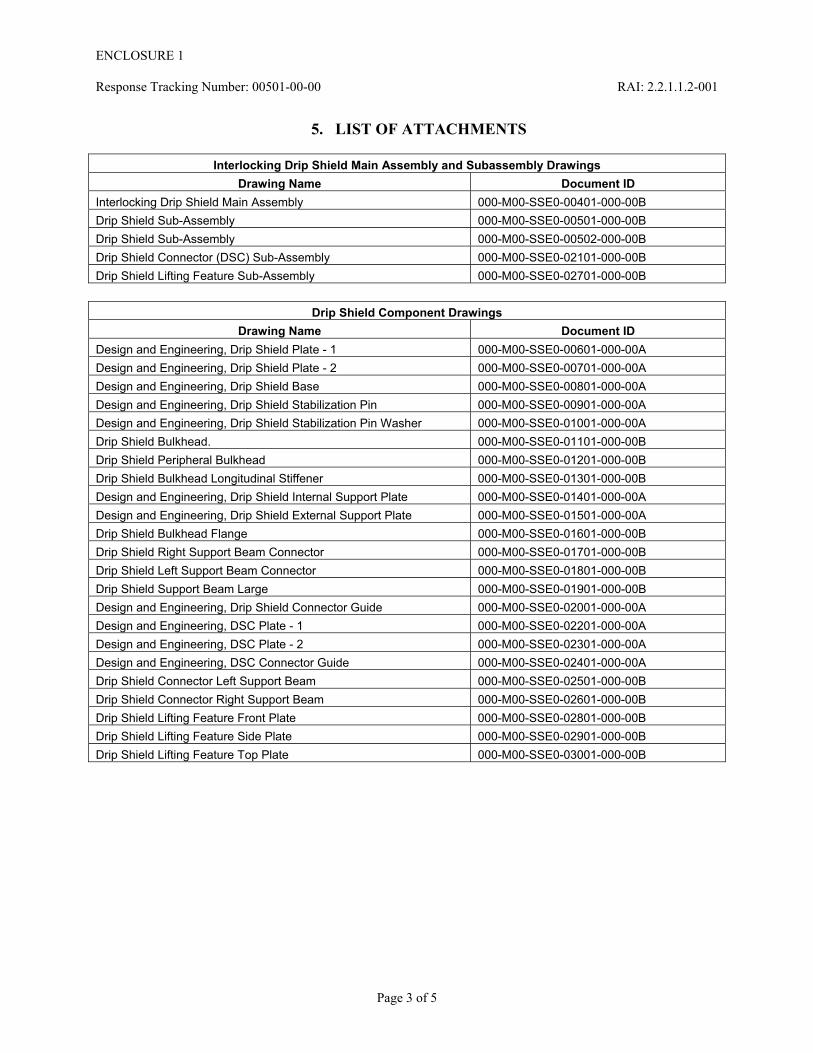
5. LIST OF ATTACHMENTS
Interlocking Drip Shield Main Assembly and Subassembly Drawings Drawing Name Document ID
Interlocking Drip Shield Main Assembly 000-M00-SSE0-00401-000-00B Drip Shield Sub-Assembly 000-M00-SSE0-00501-000-00B Drip Shield Sub-Assembly 000-M00-SSE0-00502-000-00B Drip Shield Connector (DSC) Sub-Assembly 000-M00-SSE0-02101-000-00B Drip Shield Lifting Feature Sub-Assembly 000-M00-SSE0-02701-000-00B
Drip Shield Component Drawings Drawing Name Document ID
Design and Engineering, Drip Shield Plate - 1 000-M00-SSE0-00601-000-00A Design and Engineering, Drip Shield Plate - 2 000-M00-SSE0-00701-000-00A Design and Engineering, Drip Shield Base 000-M00-SSE0-00801-000-00A Design and Engineering, Drip Shield Stabilization Pin 000-M00-SSE0-00901-000-00A Design and Engineering, Drip Shield Stabilization Pin Washer 000-M00-SSE0-01001-000-00A Drip Shield Bulkhead. 000-M00-SSE0-01101-000-00B Drip Shield Peripheral Bulkhead 000-M00-SSE0-01201-000-00B Drip Shield Bulkhead Longitudinal Stiffener 000-M00-SSE0-01301-000-00B Design and Engineering, Drip Shield Internal Support Plate 000-M00-SSE0-01401-000-00A Design and Engineering, Drip Shield External Support Plate 000-M00-SSE0-01501-000-00A Drip Shield Bulkhead Flange 000-M00-SSE0-01601-000-00B Drip Shield Right Support Beam Connector 000-M00-SSE0-01701-000-00B Drip Shield Left Support Beam Connector 000-M00-SSE0-01801-000-00B Drip Shield Support Beam Large 000-M00-SSE0-01901-000-00B Design and Engineering, Drip Shield Connector Guide 000-M00-SSE0-02001-000-00A Design and Engineering, DSC Plate - 1 000-M00-SSE0-02201-000-00A Design and Engineering, DSC Plate - 2 000-M00-SSE0-02301-000-00A Design and Engineering, DSC Connector Guide 000-M00-SSE0-02401-000-00A Drip Shield Connector Left Support Beam 000-M00-SSE0-02501-000-00B Drip Shield Connector Right Support Beam 000-M00-SSE0-02601-000-00B Drip Shield Lifting Feature Front Plate 000-M00-SSE0-02801-000-00B Drip Shield Lifting Feature Side Plate 000-M00-SSE0-02901-000-00B Drip Shield Lifting Feature Top Plate 000-M00-SSE0-03001-000-00B

Page 4 of 5
ENC
LOSU
RE 1
Response Tracking N
umber: 00501-00-00
RA
I: 2.2.1.1.2-001Table 1. List of Drip Shield Components
Preferred Terminology Acceptable for Clarity or Brevity
Description (Material)
Number of Units
Reference Drawings
Drip Shield Top Plate Drip Shield Plate-1 The plate that covers the top of the drip shield (Titanium Grade 7 UNS R52400)
1 000-M00-SSE0-00501-000 000-M00-SSE0-00601-000
Drip Shield Sidewall Drip Shield Plate-2 The vertical plate on either side of the drip shield (Titanium Grade 7)
2 000-M00-SSE0-00501-000 000-M00-SSE0-00701-000
Internal Support Plate NA Support plate located at the drip shield corner below the top plate (Titanium Grade 7)
10 000-M00-SSE0-00501-000 000-M00-SSE0-01401-000
External Support Plate NA Support plate located at the drip shield corner on the outer surface of the side wall (Titanium Grade 7)
10 000-M00-SSE0-00501-000 000-M00-SSE0-01501-000
Drip Shield Connector Plate
Connector Plate; DSC Plate-1 Plates designed to connect one drip shield to another (Titanium Grade 7)
1 000-M00-SSE0-00401-000 000-M00-SSE0-02101-000 000-M00-SSE0-02201-000
Water Diversion Ring Drip Shield Connector Guide Structural connector rings located below the connector plates (Titanium Grade 7)
2 000-M00-SSE0-00501-000 000-M00-SSE0-02001-000
Bulkhead NA The structural support member located under the top plate that spans from one side wall to the other (Titanium Grade 29 UNS R56404)
4 000-M00-SSE0-00501-000 000-M00-SSE0-01101-000
Longitudinal Stiffener Bulkhead Longitudinal Stiffener
The structural support member located under the top plate that runs in longitudinal (axial) direction (Titanium Grade 29)
15 000-M00-SSE0-00501-000 000-M00-SSE0-01301-000
Support Beam NA; Support Beam Large High-strength vertical beam located on the outer surface of the side wall (Titanium Grade 29)
8 000-M00-SSE0-00501-000 000-M00-SSE0-01901-000
Base Base Plate Base plate (Alloy 22 UNS N06022) mechanically attached to the bottom of the side walls
2 000-M00-SSE0-00501-000 000-M00-SSE0-00801-000
Right Support Beam Connector
NA Vertical beam located on the outer surface of the side wall, on the right side (Titanium Grade 29)
2 000-M00-SSE0-00501-000 000-M00-SSE0-01701-000
Left Support Beam Connector
NA Vertical beam located on the outer surface of the side wall, on the left side (Titanium Grade 29)
2 000-M00-SSE0-00501-000 000-M00-SSE0-01801-000
Peripheral Bulkhead NA Bulkheads at the ends of the drip shield (Titanium Grade 29)
2 000-M00-SSE0-00501-000 000-M00-SSE0-01201-000

ENC
LOSU
RE 1
Response Tracking N
umber: 00501-00-00
RA
I: 2.2.1.1.2-001
Page 5 of 5
Preferred Terminology Acceptable for Clarity or Brevity
Description (Material)
Number of Units
Reference Drawings
Bulkhead Flange NA Flanges flanking the bulkheads (Titanium Grade 29)
8 000-M00-SSE0-00501-000 000-M00-SSE0-01601-000
Stabilization Pin NA Pin attaching the base to the side wall (Alloy 22) 10 000-M00-SSE0-00501-000 000-M00-SSE0-00901-000
Stabilization Pin Washer NA Washers at either end of stabilization pin, welded to the pin to hold it in place (Alloy 22)
20 000-M00-SSE0-00501-000 000-M00-SSE0-00502-000 000-M00-SSE0-01001-000
DSC Plate-2 Drip Shield Connector Plate-2 Side wall plate for drip shield connector subassembly (Titanium Grade 7)
2 000-M00-SSE0-02101-000 000-M00-SSE0-02301-000
DSC Connector Guide Drip Shield Connector Guide Connector guides under DSC Plate-1, drip shield connector subassembly (Titanium Grade 29)
2 000-M00-SSE0-02101-000 000-M00-SSE0-02401-000
DSC Left Support Beam Connector
Drip Shield Connector Left Support Beam Connector
Support beam at front edge of DSC subassembly, left side, welded to inside surface of DSC Plate-2 (Titanium Grade 29)
1 000-M00-SSE0-02101-000 000-M00-SSE0-02501-000
DSC Right Support Beam Connector
Drip Shield Connector Right Support Beam Connector
Support beam at front edge of DSC subassembly, right side, welded to inside surface of DSC Plate-2 (Titanium Grade 29)
1 000-M00-SSE0-02101-000 000-M00-SSE0-02601-000
Drip Shield Lifting Feature Front Plate
NA Front plate part of the drip shield lifting feature subassemblies (Titanium Grade 29)
4 000-M00-SSE0-00401-000 000-M00-SSE0-02701-000 000-M00-SSE0-02801-000
Drip Shield Lifting Feature Side Plate
NA Side plate part of the drip shield lifting feature subassemblies (Titanium Grade 29)
8 000-M00-SSE0-00401-000 000-M00-SSE0-02701-000 000-M00-SSE0-02901-000
Drip Shield Lifting Feature Top Plate
NA Top plate part of the drip shield lifting feature subassemblies (Titanium Grade 29)
4 000-M00-SSE0-00401-000 000-M00-SSE0-02701-000 000-M00-SSE0-03001-000
NOTE: SAR Figure 1.3.4-14 provides component identification. NA = not applicable.
Shaded text identifies text that supplements information already provided in SAR Table 1.3.4-4.

ENCLOSURE 2
Response Tracking Number: 00502-00-00 RAI: 2.2.1.1.2-002
RAI Volume 2, Chapter 2.1.1.2, First Set, Number 2
Provide details of the drip shield interlocking feature shown in SAR Figure 1.3.4-15, including dimensions of various components.
DOE has indicated that SAR Figure 1.3.4-15 provides details of the drip shield interlocking feature. However, the Figure 1.3.4-15 does not explicitly show details necessary for evaluation of the drip shield installation and drip shield structural performance as ITWI SSC.
1. RESPONSE
Supplemental and Other Related Information─ The response to RAI 2.2.1.1.2-001 provided a complete set of the drip shield main assembly, sub-assemblies, and parts drawings, including details of the interlocking features. The information in that response is supplemental to information previously contained in SAR Section 1.3.4.7. The complete set of drawings contains details and dimensions that facilitate demonstration and verification of the drip shield interlocking process.
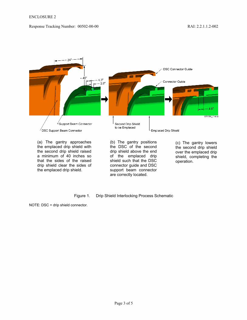
This response includes a sequence of isometric sketches (Figure 1) that illustrate the interlocking process as the drip shield connector (DSC) portion of a second drip shield is brought into an interlocking position over an already emplaced drip shield, and lowered into position to complete the interlocking operation. Only partial views are used, and the drip shield gantry and waste package are not shown in order to clearly illustrate the interlocking operation.
Two other figures are also included with the response to demonstrate the height clearance requirement for moving into position the DSC portion of one drip shield over the receiving end of an emplaced drip shield (Figure 2), and to illustrate the description of the interlocking process (Figure 3), as requested in the teleconference with the NRC on July 9, 2009.
Description of the Drip Shields Interlocking Process─ As described in SAR Section 1.3.4.7, a rail-based drip shield emplacement gantry (SAR Figure 1.3.4-17) is used for carrying the drip shields from a storage location at the surface into the emplacement drifts. The gantry uses the same rail and support systems as those used by the transport and emplacement vehicle. The gantry carries a single drip shield in a horizontal orientation by engaging four lifting hooks, two to each side attached to a lifting beam, to corresponding lifting features on the sides of the drip shield (SAR Figure 1.3.4-14).
This drip shield interlocking operation consists of overlapping an already emplaced drip shield with the DSC portion of the second drip shield and lowering the second drip shield into place. Interlocking of the two drip shields is controlled by positioning the second drip shield’s DSC connector guide (top) and DSC support beam connectors (sides) beyond the emplaced drip shield’s connector guide and support beam connectors, so that the two drip shields become mechanically connected in their emplaced position when resting on the invert structure.
Page 1 of 5

ENCLOSURE 2
Response Tracking Number: 00502-00-00 RAI: 2.2.1.1.2-002
The drip shield gantry carrying the second drip shield approaches the emplaced drip shield with the second drip shield raised to a position that is a minimum of 40 inches (measured crown to crown or 40 inches above the invert) above the emplaced drip shield (Figure 1 (a)). This elevation offset between the two drip shields is required due to the interference fit of the sides between the drip shields that results from the splaying of side walls and associated structural members (Figure 2). The 40-inch elevation of the second drip shield is sufficient to permit the second drip shield’s DSC support beam connectors (on the sides) to clear the emplaced drip shield’s support beam connectors (Figure 1(a)) before the drip shield lowering process begins. The two drip shields’ beam connectors make contact on the sides at an elevation less than 40 inches above the invert structure (Figure 2).
After the DSC support beam connectors clear the emplaced drip shield support beam connectors on the sides, the DSC is in the correct position over the emplaced drip shield and the gantry lowers the second drip shield (Figure 1 (b)). After the second drip shield is lowered into the interlocking position, its DSC support beam connectors, which are on the inside of the DSC assembly, are positioned beyond the support beam connectors of the emplaced drip shield, which are on the outside of the emplaced drip shield, completing the interlocking operation (Figure 1(c)). The two drip shields thus become interlocked by the DSC connector guide-to-connector guide interface at the top and by the DSC support beam connectors-to-support beam connectors interfaces on the sides. This interference fit creates a very strong joint against longitudinal separation of the drip shields. Furthermore, the height to which adjacent drip shields must be raised to result in separation helps ensure that the drip shields will not separate during seismic events.
When the two drip shields are completely interlocked, the two connector guides will be either adjacent to each other (in contact) or separated approximately 4.6 inches apart (Figure 1(c) and Figure 3(a)). Contact between the two drip shield assemblies along the drift axis limits the connector guides separation to 4.6 inches. Figure 3 illustrates the position of the DSC support beam connector (second drip shield) with respect to the support beam connector (emplaced drip shield) on either side of the interlocked drip shields after the interlocking operation is complete. The figure identifies an approximate 4.9-inch maximum interlocking tolerance gap (Figure 3 (b)) for the DSC support beam connector-to-support beam connector interface.
2. COMMITMENTS TO NRC
None.
3. DESCRIPTION OF PROPOSED LA CHANGE
None.
Page 2 of 5
ENCLOSURE 2
Response Tracking Number: 00502-00-00 RAI: 2.2.1.1.2-002
(b) The gantry positions the DSC of the second drip shield above the end of the emplaced drip shield such that the DSC connector guide and DSC support beam connector are correctly located.
(c) The gantry lowers the second drip shield over the emplaced drip shield, completing the operation.
(a) The gantry approaches the emplaced drip shield with the second drip shield raised a minimum of 40 inches so that the sides of the raised drip shield clear the sides of the emplaced drip shield.
Figure 1. Drip Shield Interlocking Process Schematic
NOTE: DSC = drip shield connector.
Page 3 of 5

ENCLOSURE 2
Response Tracking Number: 00502-00-00 RAI: 2.2.1.1.2-002
Figure 2. Height Difference below which there is Contact at the Sides (Support Beams) of Drip Shields to be Interlocked
Page 4 of 5

ENCLOSURE 2
Response Tracking Number: 00502-00-00 RAI: 2.2.1.1.2-002
Page 5 of 5
(a) Connector guides installation tolerance (horizontal) of approximately 4.6 inches
(b) Support beam connectors installation tolerance (horizontal) of approximately 4.9 inches.
NOTE: All the dimensions in this figure are approximate conversions from the original design dimensions available in metric units.
Figure 3. Interlocked Drip Shields Installation Tolerance

ENCLOSURE 3
Response Tracking Number: 00503-00-00 RAI: 2.2.1.1.2-003
RAI Volume 2, Chapter 2.1.1.2, First Set, Number: 3
Provide information pertaining to the codes and standards used for the drip shield design and fabrication, including, but not limited to, code and standards used for drip shield welding and heat treatment.
DOE has indicated that codes and standards applicable to the design and fabrication of the drip shield are provided in SAR Table 1.3.2-5. However, in the Table 1.3.2-5, DOE has listed only codes and standards that govern material properties (e.g., density, elongation, yield and ultimate tensile stresses). In “Yucca Mountain Project Engineering Specification Prototype Drip Shield” (BSC, 2007m), cited in SAR Section 1.3.4.7.7, DOE provides information on other codes and standards used for drip shield welding, heat treatment, etc.; however, this reference is not on the docket.
1. RESPONSE
1.1 DRIP SHIELD CODES AND STANDARDS IN SAFETY ANALYSIS REPORT
The drip shield provides postclosure waste isolation functions and satisfactory performance (and the associated methodology) has been demonstrated as a part of the postclosure analyses (SAR Sections 2.3.4 and 2.3.6). Codes and standards applied to the fabrication of the drip shield have been adopted from the American Society of Mechanical Engineers ASME Boiler and Pressure Vessel Code (ASME 2001), and the American Welding Society standards for welding and are sufficient to support postclosure analyses.
SAR Table 1.3.2-5 lists American Society of Mechanical Engineers and American Society for Metals international codes and standards applicable to the determination of the physical and mechanical properties of different titanium grades and Alloy 22 (UNS N06022) used in the drip shield design.
The drip shield design development prototype process will address materials’ compatibility and performance, capability to assemble within the nominal dimension, structural strength as well as weld designs and procedures. Available codes and standards, such as welding standards, will be evaluated to obtain process consistency in fabrication of drip shields. Codes and standards cited in the prototyping specification (BSC 2007) and other design documents are listed in this response. However, while the specification provides for general application of these codes and standards, more specific application (and exceptions) will be developed as part of the prototyping process.
Page 1 of 6

ENCLOSURE 3
Response Tracking Number: 00503-00-00 RAI: 2.2.1.1.2-003
1.2 DRIP SHIELD CODES AND STANDARDS—SUPPLEMENTAL INFORMATION
1.2.1 Codes and Standards from Drip Shield Prototype Specification
The Yucca Mountain Project Engineering Specification Prototype Drip Shield (BSC 2007, Sections 2.1, 4, 5, 6, and 8) identifies the following codes and standards as applicable for materials, design, fabrication, testing, examination, and shipping of the drip shield:
General
• ASME Boiler and Pressure Vessel Code (ASME 2001), Section III, Rules for Construction of Nuclear Power Plant Components, Division 1, Subsection NC, Class 2 Components, 2001 Edition with the 2002 Addenda (or the latest edition and addenda)
• ASME Boiler and Pressure Vessel Code (ASME 2001), Section III, Rules for Construction of Nuclear Power Plant Components, Division 1, Subsection NCA 4000, General Requirements for Division 1 and Division 2, 2001 Edition with 2002 Addenda (or the latest edition and addenda).
Design
• ASME Y14.36M (ASME 1996) – Surface Texture Symbols
• ASME Y14.5M-1994 (ASME 1994) – Dimensioning and Tolerancing, Reaffirmed 2004
• ANSI/AWS A2.4-98 (ANSI/AWS 2000) – Standard Symbols for Welding, Brazing, and Nondestructive Examination.
Materials
• ASME Boiler and Pressure Vessel Code (ASME 2001), Section II.
Fabrication and Assembly
• ASME Boiler and Pressure Vessel Code (ASME 2001), Section III, Division 1 – Examination and repair of the drip shield assembly
• ASME Boiler and Pressure Vessel Code (ASME 2001), Section III, Division 1, Subsection NCA 4000 – Cutting, forming, machining, and fitting operations.
Heat Treatment
• ASME Boiler and Pressure Vessel Code (ASME 2001), Section III, Division 1, NC-4600 – Heat treatment procedures.
Page 2 of 6

ENCLOSURE 3
Response Tracking Number: 00503-00-00 RAI: 2.2.1.1.2-003
Finishing
• ASME B46.1-2002 (ASME 2003) – Surface Texture (Surface Roughness, Waviness, and Lay), 2003 Edition.
Welding
• ASME Boiler and Pressure Vessel Code (ASME 2001), Section II, Part C – Specifications for Welding Rods, Electrodes, and Filler Metal, 2001 Edition with 2002 Addenda (or the latest edition and addenda)
• ASME Boiler and Pressure Vessel Code (ASME 2001), Section II, Part C, SFA-5.14, Classification ERNiCrMo-10 – UNS N06022 (Alloy-22) bare welding electrodes and rods
• ASME Boiler and Pressure Vessel Code (ASME 2001), Section II, Part C, SFA-5.16, Classification ERTi-7 ELI – Electrodes and rods for titanium Grade-7 to titanium Grade-7 welds
• ASME Boiler and Pressure Vessel Code (ASME 2001), Section II, Part C, SFA-5.16, Classification ERTi-29 – Electrodes and rods for titanium Grade-29 to titanium Grade-29 welds
• ASME Boiler and Pressure Vessel Code (ASME 2001), Section II, Part C, SFA-5.16, Classification ERTi-28 – Electrodes and rods for titanium Grade-7 to titanium Grade-29 welds
• ASME Boiler and Pressure Vessel Code (ASME 2001), Section III, Division 1, NC-2400 – Welding filler metals
• ASME Boiler and Pressure Vessel Code (ASME 2001), Section IX, Welding and Brazing Qualifications, 2001 Edition with 2002 Addenda (or the latest edition and addenda)
• ANSI/AWS A5.32/A5.32M-97 (ANSI/AWS 2007) – Specification for Welding Shielding Gases.
Testing
• ASME Boiler and Pressure Vessel Code (ASME 2001), Section III, NC-5200 – Examination of welds by visual method
• ASME Boiler and Pressure Vessel Code (ASME 2001), Section III, NC-5200 and NC-5300 – Weld nondestructive examination
Page 3 of 6

ENCLOSURE 3
Response Tracking Number: 00503-00-00 RAI: 2.2.1.1.2-003
• ASME Boiler and Pressure Vessel Code (ASME 2001), Section III, NC-5320 – Radiographic examination of UNS N06022 (Alloy-22) and titanium full penetration welds
• ASME Boiler and Pressure Vessel Code (ASME 2001), Section III, NC-5330 – Ultrasonic examination of UNS N06022 (Alloy-22) and titanium full penetration welds
• ASME Boiler and Pressure Vessel Code (ASME 2001), Section III, NC-5350 – Examination by liquid penetrant methods of welds using ASME Boiler and Pressure Vessel Code (ASME 2001), Section III, Subsection NC methods
• ASME Boiler and Pressure Vessel Code (ASME 2001), Section III, NC-5352 – Acceptance criteria for liquid penetrant examination
• ASME Boiler and Pressure Vessel Code (ASME 2001), Section V, Nondestructive Examination, 2001 Edition with 2002 Addenda (or the latest edition and addenda)
• ASME Boiler and Pressure Vessel Code (ASME 2001), Section V, Article 6, T-640 – Analysis of contaminants for penetrant materials used for examination of titanium and nickel-based alloys.
Quality Assurance
• ASME NQA-1-2000 (ASME 2001) – Quality Assurance Requirements for Nuclear Facility Applications, Subpart 2.1, Quality Assurance Requirements for Cleaning of Fluid Systems and Associated Components for Nuclear Power Plants, 2000 Edition (for cleaning, packaging, and shipping only)
• ASME NQA-1-2000 (ASME 2001) – Quality Assurance Requirements for Nuclear Facility Applications, Subpart 2.2, Quality Assurance Requirements for Packaging, Shipping, Receiving, Storage and Handling of Items of Nuclear Power Plants, 2000 Edition
• ASME Boiler and Pressure Vessel Code (ASME 2001), Section III, NCA-4134.17 – Maintenance of records.
1.2.2 Codes and Standards from Project Design Criteria
The Project Design Criteria Document (BSC 2009, Section 5) also includes codes and standards applicable to the drip shield, as follows:
Fabrication Criteria
• ASME Boiler and Pressure Vessel Code (ASME 2001), Section II and Section III, Division 1
Page 4 of 6

ENCLOSURE 3
Response Tracking Number: 00503-00-00 RAI: 2.2.1.1.2-003
• ASME Y14.38-1999 (ASME 1999-2002), as applicable to requirements for abbreviations and acronyms used in the designing of nuclear components.
Quality Assurance Criteria
• ASME NQA-1-2000 (ASME 2001), Subparts 2.1 and 2.2.
1.3 DRIP SHIELD PRECLOSURE HANDLING REQUIREMENTS
For normal drip shield handling, a feasibility calculation was performed to determine self-weight shear and tensile stresses in the lifting features of the drip shield structure. These were compared to the adjusted yield stress and ultimate tensile strength limits from American National Standard for Radioactive Materials – Special Lifting Devices for Shipping Containers Weighing 10000 Pounds (4500 kg) or More (ANSI N14.6-1993) and found to be significantly less than those limits. (Note: this ANSI standard has been withdrawn for revision, but was active at the time of the preparation of this calculation.)
The calculation assumed the lifting features of the drip shield were composed of Titanium Grade 24 (UNS R56405) rather than Titanium Grade 29 (UNS R56404). Grade 29 has minimum yield stress and tensile strength limits that are 10 ksi less than those for Grade 24; however, the margin computed in the calculation is more than sufficient to absorb this reduction in structural capability.
2. COMMITMENTS TO NRC
None.
3. DESCRIPTION OF PROPOSED LA CHANGE
None.
4. REFERENCES
ANSI N14.6-1993. American National Standard for Radioactive Materials - Special Lifting Devices for Shipping Containers Weighing 10000 Pounds (4500 kg) or More. New York, New York: American National Standards Institute. TIC: 236261.
ANSI/AWS A2.4-98. 2000. Standard Symbols for Welding, Brazing, and Nondestructive Examination. Miami, Florida: American Welding Society. TIC: 253107.
ANSI/AWS A5.32/A5.32M-97. 2007. Specification for Welding Shielding Gases. Miami, Florida: American Welding Society. TIC: 259771.
ASME (American Society of Mechanical Engineers) Y14.5M-1994. 1999. Dimensioning and Tolerancing. New York, New York: American Society of Mechanical Engineers. TIC: 253106.
Page 5 of 6
ENCLOSURE 3
Response Tracking Number: 00503-00-00 RAI: 2.2.1.1.2-003
Page 6 of 6
ASME Y14.36M-1996. Surface Texture Symbols. New York, New York: American Society of Mechanical Engineers. TIC: 253104.
ASME 2001. 2001 ASME Boiler and Pressure Vessel Code. New York, New York: American Society of Mechanical Engineers. TIC: 251425.
ASME NQA-1-2000. 2001. Quality Assurance Requirements for Nuclear Facility Applications. New York, New York: American Society of Mechanical Engineers. TIC: 253110.
ASME Y14.38-1999. 1999-2002. Abbreviations and Acronyms (with Addenda, ASME Y14.38a-2002). New York, New York: American Society of Mechanical Engineers. TIC: 258694.
ASME B46.1-2002. 2003. Surface Texture (Surface Roughness, Waviness and Lay). New York, New York: American Society of Mechanical Engineers. TIC: 257359.
BSC (Bechtel SAIC Company) 2007. Yucca Mountain Project Engineering Specification Prototype Drip Shield. 000-3SS-SSE0-00100-000-000. Las Vegas, Nevada: Bechtel SAIC Company. ACC: ENG.20071206.0013.
BSC 2009. Project Design Criteria Document. 000-3DR-MGR0-00100-000-008. Las Vegas, Nevada: Bechtel SAIC Company. ACC: DOC.20090331.0010.

ENCLOSURE 4
Response Tracking Number: 00504-00-00 RAI: 2.2.1.1.2-004
RAI Volume 2, Chapter 2.1.1.2, First Set, Number 4:
Provide technical basis for using Titanium Grade 28 as a filler material for joining Titanium grade 7 to Titanium Grade 29, including fabrication methods used to perform welding operations. Specifically, address the technical basis for the selection of the weldment, given the metallurgical, mechanical, and thermal differences between these three metals.
Titanium Grade 7 is a palladium-containing single α-phase material and titanium Grades 28 and 29 are aluminum-, vanadium-, ruthenium-containing α + β phase material. Their mechanical strengths increase in the following order: titanium Grade 7< titanium Grade 28< titanium Grade 29. These three materials also have slightly different thermal properties. The mechanical properties of the titanium Grade 7 to titanium Grade 28 to titanium Grade 29 welding joint were not provided by the applicant and they were also not available in the literature. This information is needed for evaluation of drip shield fabrication and drip shield structural performance as ITWI SSC.
1. RESPONSE
1.1 BASIS FOR SELECTION OF TITANIUM GRADE 28 WELD FILLER METAL FOR JOINING TITANIUM GRADE 7 TO TITANIUM GRADE 9
The drip shield materials were selected in order to obtain a combination of desired mechanical response under the range of expected postclosure loading conditions, adequate corrosion resistance, and resistance to the potential for hydrogen-embrittlement. The drip shield fragility analyses represent the necessary postclosure performance (SAR Section 2.3.4.5.3), as these analyses include rockfall load and account for changes in part thickness as a function of time due to corrosion. The dissimilar metal welds are modeled as having the tensile strength of Titanium Grade 7 (UNS R52400). The approach described below is consistent with other industrial applications, which have successfully applied dissimilar metal weld filler material.
To obtain the requisite mechanical response to postclosure loads (i.e., thermal, static loading by rockfall debris, seismic), all the drip shield plates (SAR Figure 1.3.4-14) are fabricated from highly corrosion-resistant Titanium Grade 7 (Titanium Grade 2 (UNS R50400) with 0.12% to 0.25 % palladium addition), and the structural members (see the detailed drip shield parts list in Table 1 of the response to RAI 2.2.1.1.2-001, and assembly, subassembly, and parts drawings submitted with that RAI response) are fabricated from higher-strength Titanium Grade 29 (UNS R56404) (Titanium-6Al-4V with extra low interstitial element content and with 0.08% to 0.14% ruthenium addition).
The use of dissimilar filler metals is based upon mitigation of hydrogen embrittlement (as described in the response to RAI 3.2.2.1.2.1-2-008), which has been observed in dissimilar metal welds between nonpalladium- or nonruthenium-containing titanium alloys that are otherwise similar in composition to Titanium Grade 7 and Titanium Grade 29. Specifically, the National Aeronautics and Space Administration (NASA) observed the development of long-term
Page 1 of 5

ENCLOSURE 4
Response Tracking Number: 00504-00-00 RAI: 2.2.1.1.2-004
hydrogen embrittlement in Saturn IVB helium tank welds between two Titanium Grade 5 (UNS R56400) plates (a Titanium-6Al-4V alloy similar to Titanium Grade 29 but without extra low interstitial content or beneficial ruthenium additions) where a Titanium Grade 2 filler was used (SNL 2007a, Section 6.3[a]). The observed cracking was the result of hydride bands that formed along the weld. In contrast, NASA used a more optimized welding process on similar-type Apollo rocket helium tank welds, which eliminated the detrimental hydride banding found for the Saturn IVB helium tank welds. To mitigate the potential for hydrogen embrittlement that might occur due to the welding of two dissimilar metals in the drip shield (i.e., Titanium Grade 7 and Titanium Grade 29), an intermediate composition weld filler metal, Titanium Grade 28 (UNS R56323) (Titanium-3Al-2.5V with extra low interstitial element content and 0.08% to 0.14% ruthenium) is used, as described in the response to RAI 3.2.2.1.2.1-2-008. Recent modeling of this weld configuration indicated that hydrogen concentrations associated with the weld will remain below the critical concentration for embrittlement of Titanium Grades 7, 28, or 29 with appropriate process controls; as such, hydride-induced cracking will not occur, supporting the viability of this approach (Mintz and He 2009). In addition to their beneficial effect on mitigating the potential for hydrogen embrittlement, the palladium or ruthenium additions contained in Titanium Grade 7 and Titanium Grade 29 increase localized corrosion resistance over a range of repository-relevant environments, as described in SAR Section 2.3.6.8 and the responses to RAI 3.2.2.1.3.1-003 and RAI 3.2.2.1.3.1-004.
1.2 DISSIMILAR METAL WELDMENT FABRICATION PROCESSES
The requirements regarding the general drip shield fabrication methods, including processes that may be used to perform welding operations, such as dissimilar metal welds, are summarized in Yucca Mountain Project Engineering Specification Prototype Drip Shield (BSC 2007). Allowable welding processes for the dissimilar metal welds include gas tungsten arc welding, gas metal arc welding, and potential alternative welding processes. The dissimilar metal weldment process to be used must be qualified in accordance with the requirements of Section III, NC-4000, and Section IX of 2001 ASME Boiler and Pressure Vessel Code (ASME 2001) and according to Yucca Mountain Project Engineering Specification Prototype Drip Shield (BSC 2007).
Drip shield weld designs have been developed, and their characteristics will be further specified as part of the detailed design and prototyping processes. The response to RAI 2.2.1.1.2-010 provides further information on the use of prototyping. The welds will be appropriately designed to meet the as-analyzed drip shield mechanical response.
1.3 MECHANICAL AND THERMAL RESPONSE OF DRIP SHIELD DISSIMILAR METAL WELDS
SAR Sections 1.3.4.7 and 2.3.4.5.1.1 provide general design information for the drip shield based on engineering drawings and design reports. A set of drawings for the drip shield piece parts, subassemblies, and main assembly has been submitted with the response to RAI 2.2.1.1.2-001 and contains additional information on welds and fabrication details. The structural performance of the drip shield is evaluated in terms of postulated postclosure events and satisfying postclosure functions. The stress magnitudes, deformations, and potential failure
Page 2 of 5

ENCLOSURE 4
Response Tracking Number: 00504-00-00 RAI: 2.2.1.1.2-004
mechanisms are evaluated using finite-element analyses and the principles of mechanics of materials in the postclosure analyses. These finite-element analyses allow verification of the drip shield performance, including evaluation in the changing emplacement drift environment during the postclosure period. The analyses consider possible drift degradation and seismic ground motions, as described in Seismic Consequence Abstraction (SNL 2007b, Sections 6.4, 6.7, and 6.8). The structural analysis methods are used to predict margin to failure by ductile tearing.
The mechanical properties of Titanium Grade 7 and Titanium Grade 29 used in the postclosure mechanical calculations are shown in Table 1. The properties selected for Titanium Grade 7 and 29 were developed and justified for use in the postclosure analyses, in Mechanical Assessment of Degraded Waste Packages and Drip Shields Subject to Vibratory Ground Motion (SNL 2007c). It should be noted that the values in Table 1 have been adjusted for a temperature of 60°C and as such may differ from published standard room temperature values. Although not modeled as part of the postclosure analyses, Table 1 includes, for information, the mechanical properties for Titanium Grade 28 at 60°C. Structural analyses were performed using finite-element analyses that modeled the welds as a portion of the exterior drip shield plates using properties for Titanium Grade 7 rather than specific mechanical properties for each of the titanium metal grades in the weld.
The thermal properties of the alloys are similar, and due to the lack of thermal gradients, these slight differences will not affect mechanical response. Specifically, the coefficient of linear thermal expansion of Titanium Grade 7, Titanium Grade 23 (UNS R56407) (analogue of Titanium Grade 29) and Titanium Grade 9 (UNS R56320) (analogue of Titanium Grade 28) are 9.2, 9.9, and 9.2 micrometers/meter-degree K, respectively (ASM 1990, Table 20). The selected failure mechanisms and design information are adequate for defining the fragility of the drip shield (SAR Section 2.3.4.5.3) through inclusion of the rockfall load and changes in part thickness as a function of time due to corrosion.
1.4 SUCCESSFUL USE OF DISSIMILAR WELD FILLER METAL
Although filler metal composition is usually matched to the base metal, unalloyed filler metal or filler metal containing lower alloying content is sometimes used to weld Titanium-6Al-4V for improved joint ductility, as documented in Materials Properties Handbook: Titanium Alloys (Boyer et al. 1994, p. 1162). The use of dissimilar metal welds in titanium structures is also sanctioned by the Guide for the Fusion Welding of Titanium and Titanium Alloys (AWS 2007, Section 7.2) for palladium and ruthenium corrosion-enhanced filler metals to achieve improved corrosion resistance. One example, provided in the Guide for the Fusion Welding of Titanium and Titanium Alloys (AWS 2007), is the welding of Titanium Grade 26 (UNS R52404) using Titanium Grade 7 filler metal (ERTi-7). Titanium Grade 26 has the same ruthenium specification as Titanium Grades 28 and 29, although these grades are stronger than Titanium Grade 7 due to the introduction of aluminum and vanadium alloying elements. For the case of nonpalladium or nonruthenium containing titanium alloys, the use of low alloy weld filler may enhance the possibility of hydrogen embrittlement, as reported in Guide for the Fusion Welding of Titanium and Titanium Alloys (AWS 2007, Section 7.2) and in Materials Properties Handbook: Titanium Alloys (Boyer et al. 1994, p. 1162). Examples cited include all α phase unalloyed titanium, e.g., Titanium Grade 2 welded to α + β phase alloys such as Titanium-3Al-2.5V (Titanium Grade 9)
Page 3 of 5

ENCLOSURE 4
Response Tracking Number: 00504-00-00 RAI: 2.2.1.1.2-004
or Titanium-6Al-4V (Titanium Grades 5 and 23). These examples are of particular relevance to the weld design proposed for the drip shield, as they illustrate welding a low-aluminum content alloy to an intermediate-aluminum content alloy in addition to a weld made between a low-aluminum content alloy and a high-aluminum content alloy. As described in the response to RAI 3.2.2.1.2.1-2-008, in the case of dissimilar metal welds in Titanium-6Al-4V (Titanium Grade 5), such as in NASA helium pressure vessels welded using Titanium Grade 2 filler metal (SNL 2007a, Section 6.3[a]), if the weld dilution of aluminum in the Titanium Grade 2 material near the weld fusion line is not properly controlled by the welding process parameters, the hydrogen concentration can increase in this fusion line region, leading to a potential for hydrogen embrittlement. However, as described in the response to RAI 3.2.2.1.2.1-2-008, with proper welding procedures, such as those discussed in Section 1.2, successful field experience joining Titanium Grade 5 with welds made using Titanium Grade 2 filler metal has been demonstrated. It is anticipated that similar optimization of welding parameters will enable the formation of a successful weld between Titanium Grade 7 and Titanium Grade 29 utilizing a Titanium Grade 28 filler metal. The beneficial effect on corrosion resistance and resistance to hydrogen embrittlement resulting from palladium or ruthenium additions and the use of intermediate composition Titanium Grade 28 filler metal to weld Titanium Grade 7 to Titanium Grade 29 were also addressed in the response to RAI 3.2.2.1.2.1-2-008.
2. COMMITMENTS TO NRC
None.
3. DESCRIPTION OF PROPOSED LA CHANGE
None.
4. REFERENCES
ASM International 1990. Properties and Selection: Nonferrous Alloys and Special-Purpose Materials. Volume 2 of ASM Handbook. Formerly Tenth Edition, Metals Handbook. Materials Park, Ohio: ASM International. TIC: 241059.
ASME (American Society of Mechanical Engineers) 2001. 2001 ASME Boiler and Pressure Vessel Code. New York, New York: American Society of Mechanical Engineers. TIC: 251425.
AWS G2.4/G2.4M:2007.2007. Guide to the Fusion Welding of Titanium and Titanium Alloys. 1st Edition. Miami, Florida: American Welding Society.
Boyer, R; Welsch, G.; and Collings, E.W. 1994. Materials Properties Handbook: Titanium Alloys. Materials Park, Ohio: ASM International. TIC: 257276.
BSC (Bechtel SAIC Company) 2007. Yucca Mountain Project Engineering Specification Prototype Drip Shield. 000-3SS-SSE0-00100-000-000. Las Vegas, Nevada: Bechtel SAIC Company. ACC: ENG.20071206.0013.
Page 4 of 5

ENCLOSURE 4
Response Tracking Number: 00504-00-00 RAI: 2.2.1.1.2-004
Page 5 of 5
Mintz, T.S., and He, X. “Modeling of Hydrogen Uphill Diffusion in Dissimilar Titanium Welds,” Corrosion 2009, Paper No. 09430. Houston, TX: NACE International.
SNL (Sandia National Laboratories) 2007a. Hydrogen-Induced Cracking of the Drip Shield. ANL-EBS-MD-000006 REV 02 ADD 01 ACN 01 ERD 01. Las Vegas, Nevada: Sandia National Laboratories. ACC: DOC.20060306.0007; DOC.20070807.0005; DOC.20081209.0003
SNL 2007b. Seismic Consequence Abstraction. MDL-WIS-PA-000003 REV 03. Las Vegas, Nevada: Sandia National Laboratories. ACC: DOC.20070928.0011.
SNL 2007c. Mechanical Assessment of Degraded Waste Packages and Drip Shields Subject to Vibratory Ground Motion. MDL-WIS-AC-000001 REV 00 ERD 2. Las Vegas, Nevada: Sandia National Laboratories. ACC: DOC.20070917.0006; DOC.20080623.0002; DOC.20081021.0001
TIMET 1993. First in Titanium Worldwide, Quality Products and Services. Denver, Colorado: Titanium Metals Corporation. TIC: 242692
Table 1. Tensile Properties of Titanium Alloys used in Drip Shield Fabrication at 60°C
Titanium Grade Yield Strength (MPa)
True Tensile Strength (MPa)
Ultimate Engineering Elongation (%)
7 316 396 25 9* (28) 565 695 17
24* (29) 862 1120 18
NOTE: The mechanical properties of Titanium Grade 28 and Titanium Grade 29 are estimated using the mechanical properties of Titanium Grade 9 and Titanium Grade 24 surrogates, respectively. This approximation is appropriate because the alloys are similar except for minor constituents.
Source: Titanium Grade 7 and Titanium Grade 24 properties are from SAR Table 2.3.4-28. Titanium Grade 9 properties are interpolated from TIMET 1993.

ENCLOSURE 5
Response Tracking Number: 00505-00-00 RAI: 2.2.1.1.2-005
RAI Volume 2, Chapter 2.1.1.2, First Set, Number 5:
Provide technical basis for the selection of the stress relief conditions of 1100 °F ± 25 °F for 120 minutes and its applicability to the Titanium Grade 7 to Titanium Grade 28 to Titanium Grade 29 welding joints.
DOE has indicated in the Yucca Mountain Project Engineering Specification Prototype Drip Shield (BSC 2007) and SAR Table 1.3.4-5, Parameter 07-13 that, after fabrication, the drip shield will be stress relieved at 1100 °F ± 25 °F for 120 minutes. According to the literature (ASM International, 2000) this is the recommended stress-relief treatment condition for Titanium Grade 7 to Titanium Grade 7 and Titanium Grade 29 to Titanium Grade 29 welds. However, welding Titanium Grade 7 to Titanium Grade 29 using Titanium Grade 28 as filler metal has never been used in the industry and has not been tested by DOE. The applicability of the stress relief condition to this dissimilar welding joint is needed for evaluation of drip shield fabrication and drip shield structural performance as ITWI SSC.
1. RESPONSE
The expected residual stress reduction resulting from the specified stress relief of 120 minutes at 1100°F ± 25°F is documented in Materials Properties Handbook: Titanium Alloys (Boyer et al., 1994). Detailed stress relief processes to be applied to the drip shield including the weld areas are based on the Titanium Grade 29 (Ti-6Al-4V with extra low interstitial element content and with 0.08-0.14% ruthenium addition) material. Titanium Grade 29 has the highest strength and is most resistant to thermal stress relaxation of the materials in the dissimilar metals weld. Thus, residual stress relaxation will be greater for the Titanium Grade 7 and the Titanium Grade 28 portions of the dissimilar metals weld.
Information contained in Materials Properties Handbook: Titanium Alloys (Boyer et al., 1994) includes a nomograph showing that when welded Ti-6Al-4V material, such as Titanium Grade 29, is heated for 120 minutes at 1075°F (the lower allowable temperature limit) the residual stresses will be reduced by approximately 52%. This level of residual stress reduction is adequate to preclude stress corrosion cracking since the conservative stress corrosion cracking-initiation threshold used by the Total System Performance Assessment is 50% of the at-temperature yield strength for Titanium Grade 29 (SAR Section 2.3.6.8.3). It is also stated in Materials Properties Handbook: Titanium Alloys (Boyer et al. 1994, p. 608):
The effect of time and temperature on stress relieving at elevated temperatures is shown in the nomograph for Ti-6Al-4V. At 595°C (1100°F), it takes 50 hours to achieve a full stress relief; a 50% stress relief would take about 1 hour at 595°C (1100°F) or 5 hours at 540°C (1000°F).
Holding the prescribed temperature for two hours (120 minutes) is adequate; however, maintaining the prescribed temperature for a longer period would further reduce residual stresses.
Page 1 of 2

ENCLOSURE 5
Response Tracking Number: 00505-00-00 RAI: 2.2.1.1.2-005
Page 2 of 2
The prototyping program for the drip shield (BSC 2007, Section 4) is described in Yucca Mountain Project Engineering Specification Prototype Drip Shield (BSC 2007). The purpose of this program is to develop qualified processes and procedures and provide assurance that the drip shield can be successfully fabricated with expected fabricated stress states. Based on prototyping results, the drip shield stress-relief conditions (e.g., temperature and/or hold time) will be modified as necessary to achieve the specified stress relief.
2. COMMITMENTS TO NRC
None.
3. DESCRIPTION OF PROPOSED LA CHANGE
None.
4. REFERENCES
Boyer, R.; Welsch, G.; and Collings, E.W. 1994. Materials Properties Handbook: Titanium Alloys. Materials Park, Ohio: ASM International. TIC: 257276.
BSC (Bechtel SAIC Company) 2007. Yucca Mountain Project Engineering Specification Prototype Drip Shield. 000-3SS-SSE0-00100-000-000. Las Vegas, Nevada: Bechtel SAIC Company. ACC: ENG.20071206.0013.

ENCLOSURE 6
Response Tracking Number: 00510-00-00 RAI: 2.2.1.1.2-010
Page 1 of 10
RAI Volume 2, Chapter 2.1.1.2, First 1, Number 10:
Explain how the capability of the waste package closure subsystem will be confirmed by demonstration testing of a full-scale prototype system (SAR Section 1.2.4.2.3.1). Specifically, address the following:
a. Clarify how performance requirements will be defined, considering functional requirements, safety classification, and performance capabilities of the Waste Package Closure system.
b. Describe in detail the iterative process of revising and modifying the Waste Package Closure Subsystem prototype, and how the performance capability of the as-built system will be evaluated against the acceptance criteria specified in Yucca Mountain Review Plan Section 2.1.1.2.
In SAR Section 1.2.4.2.3.1, DOE states that the design of the Waste Package Closure Inerting System, which includes piping and instrumentation, will be confirmed by demonstration testing of a full-scale prototype system. DOE has provided a conceptual description that is at a system functional level, based on preliminary design basis information. However, DOE has not described how the full-scale prototype system testing will be used to design the waste package closure system. This information is needed to verify compliance with 10 CFR 63.21(c)(3) and 10 CFR 63.21(c)(16).
1. RESPONSE
During the NRC clarification call of July 9, 2009, it was identified that RAI 2.2.1.1.2-004 requests similar information regarding prototyping of the drip shields. This response generically addresses DOE’s prototype development program as well as providing information that is specific to the waste package closure system prototype project. An objective of the prototype project was to demonstrate the feasibility of the waste package closure process.
The waste package, its closure system, the drip shield, and the emplacement pallet have been selected for prototyping programs prior to their use in the repository. These systems and components have been identified for prototyping programs because, although they are components or processes that can be designed using available materials (for which national consensus standards have been promulgated) and using established fabrication techniques, the service that is being proposed to support the repository has not been demonstrated for their particular applications. Accordingly, development involves evaluation and testing to ensure that conformance to the repository requirements, as well as repeatability of fabrication, can be accomplished in the finished product.

ENCLOSURE 6
Response Tracking Number: 00510-00-00 RAI: 2.2.1.1.2-010
Page 2 of 10
1.1 GENERALIZED DESCRIPTION OF THE PROTOTYPING PROCESS FOR WASTE PACKAGES, DRIP SHIELDS, AND WASTE PACKAGE CLOSURE SYSTEM
1.1.1 Development of Approach
Prototyping allows engineers and designers the ability to develop design details, confirm the suitability of a design, and evaluate interactions of systems and components prior to their use in service applications. For the several kinds of prototypes being developed for the Yucca Mountain repository (e.g., waste package closure system, waste packages, and drip shields), prototype testing is used to progressively develop and refine a fully operational system called the production design.
Prototype development will include the following major systems objectives:
• Confirm that the design can fulfill its functional objectives and design requirements
• Confirm or develop and optimize fabrication methods and application of new technologies
• Where necessary, qualify special processes (e.g., welding technology and techniques, nondestructive examination, etc.)
• Demonstrate through appropriate design testing that functional requirements are met.
The prototype testing program will support the above objectives by demonstrating that the structures, systems, and components meet functional requirements through component level, system level, and integrated plant testing, as appropriate. The testing program will also contribute to development of operating and off-normal procedures, risk-informed maintenance planning, operator training, and related operational support activities.
1.1.2 Establishing Base Requirements
Requirements for the function and performance of systems and components are based on the preclosure safety analysis and the postclosure performance assessment. Information regarding the nuclear safety design bases is presented in SAR Sections 1.6 through 1.9; the postclosure performance assessment is presented in SAR Sections 2.1 through 2.4 and their supporting references. The nuclear safety design bases identify the safety function to be performed and the controlling parameters with values, or ranges of values, that bound the design. These safety function parameters provide the bases for design criteria and more specific requirements that guide design to ensure equipment function and performance at a level that supports the safety bases. Design criteria and requirements that identify equipment functions and performance to support the nuclear safety design bases and postclosure performance assessment are presented in SAR Sections 1.2, 1.3, 1.4, and 1.5. For the waste package, these design criteria and requirements are presented in SAR Section 1.5.2. In addition to preclosure nuclear safety design bases that guide development of equipment capabilities (SAR Tables 1.5.2-6), postclosure control parameters (SAR Table 1.5.2-7) must be considered during the design process to ensure that equipment operations are within analyzed preclosure and postclosure conditions.

ENCLOSURE 6
Response Tracking Number: 00510-00-00 RAI: 2.2.1.1.2-010
Page 3 of 10
1.1.3 Refining Requirements
After upper-level requirements have been identified, they are functionally allocated and broken down into specific lower-tier requirements, assigned to the component level to guide the design effort and, as needed, more specific requirements are derived to support the design of necessary system components. As the design progresses, necessary documents (e.g., calculations, drawings, specifications, and other supporting documents) will be completed and more specific requirements derived and addressed.
1.1.4 Performance Requirements
The iterative process of refining details of the design is a fundamental part of the prototyping program strategy. A primary purpose of the prototyping program has been to confirm that specific functional and performance requirements for production systems and components can be met and are verified through analysis or testing.
1.1.5 Prototyping
Prototyping programs provide for the demonstration of system and component performance well before manufacture of production units. The results of these programs demonstrate that systems and components are designed, fabricated, and function operationally in accordance with their requirements. For example, demonstration of the waste package fabrication processes will be used to ensure that the waste packages can be manufactured in commercial fabrication shops using conventional manufacturing techniques.
As problems are encountered during the prototyping process, design changes will be evaluated and implemented as necessary to assure that the system or component will meet its design requirements. It is important to note that manufacturing of prototypes is an integral part of the design process. Results of the prototyping program include identifying parameters for testing as the program proceeds. Depending on the testing outcome, the results may indicate a need for modification of design details or process refinement for production systems and components.
1.2 DESCRIPTION OF THE WASTE PACKAGE CLOSURE SYSTEM PROTOTYPE PROGRAM
The prototype program initiated and conducted for the Yucca Mountain repository will demonstrate the feasibility of the waste package closure process. The action described below is the initial step in the prototype process for the waste package closure system.
The Idaho National Laboratory was tasked with design, development, and fabrication of a full-scale prototype closure system, with at least one demonstration of equipment and processes. The demonstration of the waste package closure process was performed from March 24 through March 28, 2009.
1.2.1 Identify Requirements
A primary consideration in determining the objectives of the waste package closure system prototype project was to identify requirements to ensure that project results would be responsive to repository operational concepts and needs as well as technical and quality requirements. These
ENCLOSURE 6
Response Tracking Number: 00510-00-00 RAI: 2.2.1.1.2-010
Page 4 of 10
high-level requirements were broken down into quantifiable aspects for performance requirements and allocated to waste package closure subsystems based on the waste package closure system architecture. A design description was developed at the subsystem level based on the operating requirements, boundaries and interfaces with other systems including utilities, and physical location and layout. Design requirements were then developed to implement the proposed design. The design requirements to be satisfied included performance measures, confirmation methods, and a source for each requirement.
Engineering design outputs prepared for the waste package closure system prototype project contain the basis for the engineering design. These documents include calculations and analyses, technical studies, investigations, feasibility studies, and other related information. Specifications document detailed, precise acceptance criteria for items, materials, or products.
The waste package closure system and its subsystems have been categorized as not important to safety (non-ITS) and not important to waste isolation except for the bridge of the remote handling system, which is categorized as ITS. The remote handling system bridge is required not to drop on the waste package and is classified as ITS in order to protect against structural collapse of the bridge due to a spectrum of seismic events.
1.2.2 Design the Waste Package Closure Process
The major subsystems of the waste package closure system are welding, nondestructive examination, inerting, stress mitigation, material handling, and controls and data management. Operational concepts, process flow diagrams, schematics, layouts, equipment drawings, and specifications were prepared for the major subsystems as the waste package closure system prototype project advanced. Existing nuclear industry experience in the welding, nondestructive examination, and inerting fields was adapted to support the objectives of the project. The specific application of these technologies to waste package closure, considering the materials and conditions in the repository application, required development of unique equipment and process details. Technology development was necessary in selected areas when items were not commercially available or commercially available items required modification for the specific application. For example, a need was identified for a gas tungsten arc welding torch with air cooling that would tolerate high amperage. To address this issue, a standard liquid cooled torch was modified to support air cooling. Mockups were constructed to evaluate how well an initial design of a component performed and provide insight into design improvements. Proof of principle testing was used to identify which process design options were not successful or where further development of a workable concept was necessary. The degree of the mockup testing depended on the complexity of the component. An example is the welding and nondestructive examination development process that began with bench-size rectangular coupons, evolved to large circular coupons, then finished with a full diameter waste package mockup. Integration among subsystems was performed continuously.
1.2.3 Procure and Install Demonstration Equipment
A preliminary review of potential vendors of major closure system equipment was performed. Equipment items were categorized as either commercially available, available with modifications, or not available. Technical needs varied among different subsystems and each need was evaluated individually. The waste package closure system prototype project used

ENCLOSURE 6
Response Tracking Number: 00510-00-00 RAI: 2.2.1.1.2-010
Page 5 of 10
commercially available equipment whenever possible. Modification of an existing design to meet specific requirements was preferred when commercial items were not available. Development and engineering design of new components were used as a last option. Most equipment was initially installed in laboratories for evaluation and preliminary integration. As designs matured, the equipment was moved into the demonstration facility. Larger pieces of equipment, such as the remote handling system and the floor-mounted rotating bearing used to support the robotics, were installed directly into the demonstration facility. Following component-level checkouts and testing, integration checks of interconnected components and subsystems were performed to demonstrate operability before the demonstration.
Prior to moving the equipment to the demonstration facility, the methods of design confirmation were informal design review, formal design review, technical checking, and testing. Formal design reviews were conducted by Idaho National Laboratory staff and external, independent teams. The final integration and testing of the subsystems of the waste package closure system prototype occurred in the demonstration facility.
1.2.4 Perform Prototype Demonstration
The demonstration of the integrated waste package closure system was completed to confirm that the equipment could perform the waste package closure process according to the requirements. A waste package mockup was used that was sized to accommodate a transportation, aging, and disposal canister and consisted of a full-diameter configuration with a short-height stainless steel inner vessel and Alloy 22 (UNS N06022) outer corrosion barrier. The demonstration facility simulated the Canister Receipt and Closure Facility and the Initial Handling Facility closure room, equipment room, and operations room.
1.2.5 Prototype Demonstration Results
The following principal functions of the waste package closure system were successfully demonstrated:
• Seal welding of the inner lid spread ring; seal welding of the purge port cap; narrow groove welding of the outer lid
• Nondestructive examination of the welds
• Evacuation and helium backfill of the inner vessel
• Leak detection of the inner lid seals
• Stress mitigation of the outer lid groove weld.
The overall feasibility of the waste package closure process using remote controls was successfully demonstrated. The demonstration showed acceptable performance of the functions by the integrated prototype waste package closure system.
Figure 1 is a photograph of the waste package closure system prototype in the demonstration facility. This figure shows the two robotic welding arms on the floor mounted rotating bearing. The floor opening diameter is 9 ft.

ENCLOSURE 6
Response Tracking Number: 00510-00-00 RAI: 2.2.1.1.2-010
Page 6 of 10
Figure 1. Overview of the Waste Package Closure System Prototype
Source: Original
1.3 DESCRIPTION OF THE INERTING SUBSYSTEM DEVELOPMENT
A brief description of the inerting subsystem is provided as an example of the process implemented for the waste package closure system prototype. The inerting subsystem provides evacuation of the waste package inner vessel and subsequent backfilling and pressurization with helium. Confirmation of inerting capabilities is necessary to meet repository requirements for long-term postclosure conditions.
1.3.1 Inerting Subsystem Design
Although inerting of canisters is routinely performed at nuclear power facilities when fuel assemblies are being containerized, the number of such operations per year is typically low. By contrast, the number of waste packages requiring inerting at the repository will be much greater, leading to the potential for higher cumulative exposure for workers. Thus, all inerting operations at the repository will be performed using remote-controlled systems. This approach differs from nuclear power facilities where some tasks in the inerting process are performed manually by facility workers.
The inerting subsystem supports the project level requirement that all waste packages shall be vacuum dried and backfilled with helium in a manner consistent with that described in Standard Review Plan for Dry Cask Storage Systems, NUREG-1536, Section 8.V.1. The component design description for the inerting subsystem contains the specific component level requirements based on NUREG-1536. For example, the inerting subsystem must have the following capabilities: evacuate air or helium from the waste package inner vessel; draw a vacuum to 3 Torr; maintain a constant pressure without additional evacuation for a period of 30 minutes;

ENCLOSURE 6
Response Tracking Number: 00510-00-00 RAI: 2.2.1.1.2-010
Page 7 of 10
limit the maximum quantity of oxidizing gases to a total of 1 gram-mole; backfill the waste package inner vessel with helium; and verify the helium purity.
Two of the primary components of the inerting subsystem are the equipment skid and the purge port tool. The equipment skid houses a vacuum pump, chiller, valve manifolds, controls, and a helium analyzer. The purge port tool connects to the inner lid lifting ring around the purge port and is used to evacuate, backfill, and pressurize the waste package with helium. It also partially retracts the purge port plug and screws the plug back down into the inner lid after pressurization.
Because inerting of waste packages remotely is a specialized process, evaluation of design alternatives and trade-off studies were frequently necessary to develop features of the inerting subsystem components. Following are examples of the iterative process of design evolution that was implemented to develop these parts for the inerting subsystem skid and purge port tool.
1.3.2 Inerting Subsystem Demonstration
For the inerting subsystem skid design, determining the physical arrangement of the components on a skid that would physically fit within the closure room required a number of layout iterations after selection of the major components.
Several iterations of equipment modifications and process procedural revisions were performed during testing of the purge port tool and skid components. This iterative process led to an equipment configuration that successfully met testing expectations.
The sizing and design of the inerting subsystem was based on a conservative waste package configuration that included the internal volume of the largest, empty inner vessel. This design approach ensured that the inerting subsystem tested will function satisfactorily with the waste package configurations that will be processed at the Yucca Mountain repository. The testing process demonstrated that the inerting subsystem is capable of pulling the required vacuum, backfilling the inner vessel with helium, and verifying the helium purity.
For the inerting subsystem purge port tool, two design aspects were refined, the drive head and the inner lid seal. A primary function of the purge port plug drive assembly is to screw the purge port plug in and out of the inner lid using a drive head that engages the purge port plug. The drive head design configuration was evaluated and refined for enhanced operation. In addition to development of the drive head, the seal between the purge port tool and the inner lid was also refined through design evaluation and testing of various configurations and materials to meet the elevated temperature and radiation requirements.
As part of the waste package closure system prototype demonstration in March 2009, the waste package inerting function was tested by conducting the evacuation and helium backfill process on the inner vessel using the purge port tool and the skid. The demonstration test of the inerting subsystem was performed successfully and included completion of the following key system operations: unscrewing and screwing back down of the purge port plug; evacuation of the inner vessel; maintenance of the vacuum; backfilling of the inner vessel with helium; holding the helium pressure to perform leak testing; and checking the helium concentration. Some problems were encountered with seating the purge port plug in order to compress the metal gasket. Also, the temporary heating system located inside the inner vessel of the waste package mockup did

ENCLOSURE 6
Response Tracking Number: 00510-00-00 RAI: 2.2.1.1.2-010
Page 8 of 10
not function properly so it was not possible to simulate the expected temperature. Recommendations and lessons learned were recorded, and a retest under high temperature conditions will be planned. A design modification may be needed on the purge port plug and inner lid seating surface at the purge opening in order to ensure proper seating of the gasket. An additional consideration for design is the further evaluation of the skid location in the closure room with regard to access of nearby components. As part of the process to design the production version of the waste package closure system, the next step would be a more detailed evaluation of the inerting subsystem design and integration of the demonstration test results.
The experience from the waste package closure system prototype project helped refine the design of the inerting subsystem by identifying enhancements that could be made to improve the design and features for it to perform at required levels. Figures 2 and 3 show the prototype purge port tool; the spread ring leak test tool is also shown. Figure 2 shows the purge port tool without the exterior cover. Figure 3 shows the purge port tool with the exterior cover in place in the center of the waste package mockup during the demonstration.
Figure 2. Prototype Purge Port Tool Without Exterior Cover
Source: Original

ENCLOSURE 6
Response Tracking Number: 00510-00-00 RAI: 2.2.1.1.2-010
Page 9 of 10
Figure 3. Prototype Purge Port Tool on the Waste Package Mockup
Source: Original
1.4 FOLLOW-ON DEVELOPMENT PROCESS
The completion of the waste package closure system prototype project will consist of additional development stages, final design confirmation, and a full-scale demonstration. The development of requirements for follow-on prototyping will include an evaluation of the principles of operation for the system that is integrated into overall facility operations. Given these principles, the proposed design will allow development of requirements that satisfy the analyses of the preclosure and postclosure safety bases. This process will include evaluation of the information that has been generated during this initial prototyping phase and incorporation of the information into the waste package closure system design. As prototyping programs are implemented for the other identified systems and components (e.g., waste package, drip shield, and emplacement pallet), the iterative process of incorporating prototyping test information and design refinement will continue into final design, full-scale testing, and production unit design.
Incremental system tests and evaluations that will be performed during system assembly will culminate in a full system qualification test. A qualification test is a formal detailed test with a documented test plan, evaluation, and report of observations, measurements, results, and conclusions. The full system qualification test will be performed to confirm integration and operation.
Implementation of the prototyping program for the waste package closure system demonstrated the suitability of the design to satisfy operational requirements and provided information that will be used to refine the design and improve processes for closure of production waste packages. A similar approach will be implemented during the prototyping programs for the waste package, drip shield, and emplacement pallet. The overall objectives will be the same as for the waste package closure system prototype project: demonstrate suitability of design, accept performance of functions, confirm effective interaction of systems and components, conform to the repository requirements, and demonstrate feasibility of fabrication.
ENCLOSURE 6
Response Tracking Number: 00510-00-00 RAI: 2.2.1.1.2-010
Page 10 of 10
2. COMMITMENTS TO NRC
None.
3. DESCRIPTION OF PROPOSED LA CHANGE
None.
4. REFERENCES
NRC (U.S. Nuclear Regulatory Commission) 1997. Standard Review Plan for Dry Cask Storage Systems. NUREG-1536. Washington, D.C.: U.S. Nuclear Regulatory Commission. ACC: MOL.20010724.0307.