restaurants - building in...
TRANSCRIPT

Page 1 of 29
RestaurantsMechanical & Plumbing,
Including Bathroom Requirements
Table of Contents
PlumbingCity Of Oakland Plumbing Code Requirements For Restrooms & Restaurants .................................................... 2–3
Handicapped Restroom Clearances .................................................................................................................................4–7
Request for Alternate Materials and Methods of Construction or Grant of Modification ..................................... 8–9
Plumbing Appliance, Appurtenance or Fixture Table .......................................................................................................10
Fats, Oils and Grease (FOG) Control Grease Control Device Requirements ................................................. 11–14
EBMUD Approved List of Grease Removal Devices ......................................................................................................15
Automatic Grease Removal Device: How It Works..........................................................................................................16
Gravity Grease Interceptor: Example of a 500-Gallon Gravity Grease Interceptor.................................................. 17
Hydro-mechanical Grease Interceptor: Example ..............................................................................................................18
Fats, Oils & Grease (FOG) Requirements .........................................................................................................................19
Automatic Grease Removal Devices with Internal & External Flow Control ...............................................................20
Automatic Grease Removal Device Located Underfloor with External Control .........................................................21
Commercial Dishwasher .........................................................................................................................................................22
2 Compartment Food Prep Sink with Indirect Drain ........................................................................................................23
Backflow Devices for Carbonated Beverages & Espresso Machines: 2 Examples .................................................24
MechanicalHood & Vent for 1- Story Building ........................................................................................................................................25
Hood & Vent for 2- Story Building ........................................................................................................................................26
Hood, Duct & Shaft, with Bends in Shaft ...........................................................................................................................27
Construction Assemblies Containing Noncombustible, Limited Combustible & Combustible Materials
NFPA 96 Table A.3.3.36 ........................................................................................................................................................28
Acceptable Welds for Grease Ducts for Type l Hoods, Based on NFPA 96 Standards ........................................29
Page 2 of 29
Restaurants: Plumbing
Illustration by Paddy Morrissey courtesy of Code Check ©2013** No copying, reproduction or publishing without the written permission of Code Check.
Inquires to: [email protected]
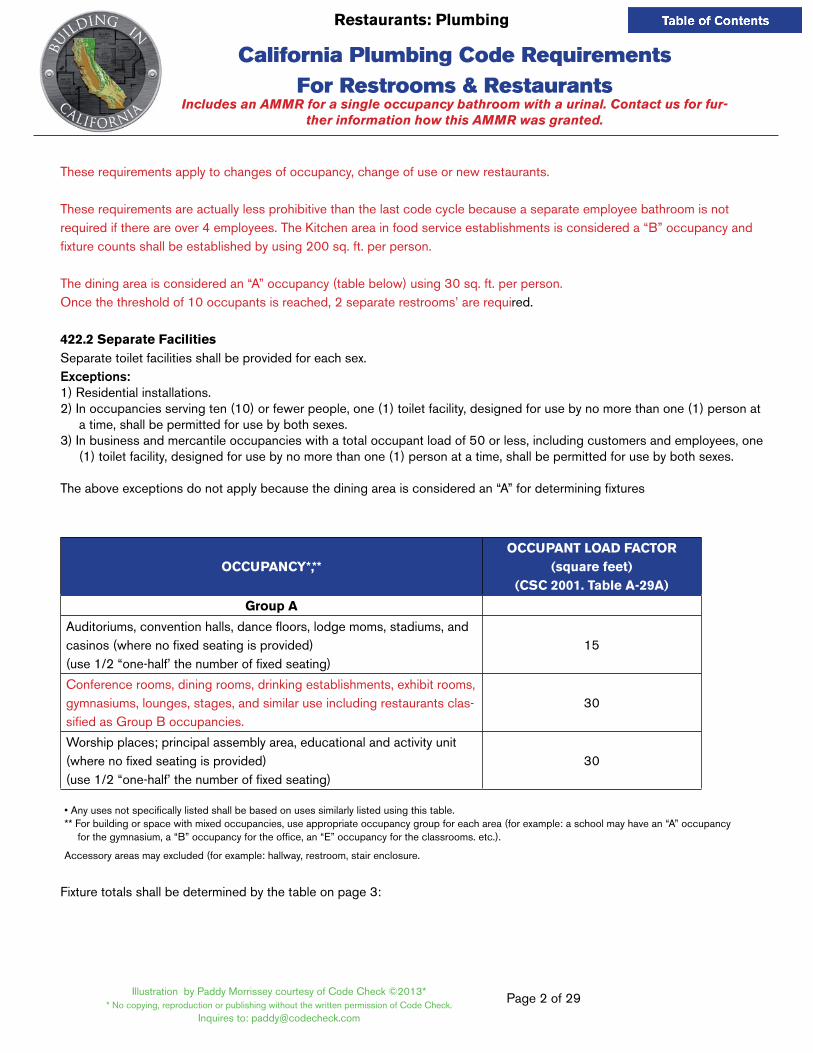
These requirements apply to changes of occupancy, change of use or new restaurants.
These requirements are actually less prohibitive than the last code cycle because a separate employee bathroom is not required if there are over 4 employees. The Kitchen area in food service establishments is considered a “B” occupancy and fixture counts shall be established by using 200 sq. ft. per person.
The dining area is considered an “A” occupancy (table below) using 30 sq. ft. per person.Once the threshold of 10 occupants is reached, 2 separate restrooms’ are required.
422.2 Separate FacilitiesSeparate toilet facilities shall be provided for each sex.Exceptions:1) Residential installations.2) In occupancies serving ten (10) or fewer people, one (1) toilet facility, designed for use by no more than one (1) person at
a time, shall be permitted for use by both sexes.3) In business and mercantile occupancies with a total occupant load of 50 or less, including customers and employees, one
(1) toilet facility, designed for use by no more than one (1) person at a time, shall be permitted for use by both sexes.
The above exceptions do not apply because the dining area is considered an “A” for determining fixtures
OCCUPANCY*,**OCCUPANT LOAD FACTOR
(square feet) (CSC 2001. Table A-29A)
Group A
Auditoriums, convention halls, dance floors, lodge moms, stadiums, and casinos (where no fixed seating is provided)(use 1/2 “one-half’ the number of fixed seating)
15
Conference rooms, dining rooms, drinking establishments, exhibit rooms, gymnasiums, lounges, stages, and similar use including restaurants clas-sified as Group B occupancies.
30
Worship places; principal assembly area, educational and activity unit(where no fixed seating is provided)(use 1/2 “one-half’ the number of fixed seating)
30
• Any uses not specifically listed shall be based on uses similarly listed using this table. ** For building or space with mixed occupancies, use appropriate occupancy group for each area (for example: a school may have an “A” occupancy
for the gymnasium, a “B” occupancy for the office, an “E” occupancy for the classrooms. etc.).
Accessory areas may excluded (for example: hallway, restroom, stair enclosure.
Fixture totals shall be determined by the table on page 3:
California Plumbing Code Requirements For Restrooms & Restaurants
Includes an AMMR for a single occupancy bathroom with a urinal. Contact us for fur-ther information how this AMMR was granted.

Page 3 of 29
Restaurants: Plumbing
Illustration by Paddy Morrissey courtesy of Code Check ©2013** No copying, reproduction or publishing without the written permission of Code Check.
Inquires to: [email protected]
TYPe OF BUiLDiNG2 OR OCCUPANCY
WATeR CLOSeTS14
(FiXTUReS PeR PeRSON)URiNALS5,10
(FiXTUReS PeR PeRSON)LAVATORieS
(FiXTUReS PeR PeRSON)
Restaurants, pubs, and lounges11,15
Male:
1. 1–50
2. 51–150
3. 150–300
Female:
1. 1–50
2. 51–150
3. 150–300Over 300, add one
additional fixture per 200 persons.
Male: 1. 1–150
Over 150, add one additional fixture per 150 Persons
Male:
1. 1–150
2. 151–200
3. 200–400
Female:
1. 1–150
2. 151–200
3. 200–400
Over 400, add one additional fixture per
400 persons.
Office or public buildings - for employee use
(Use 200 sq. ft. per person)
Male:
1. 1–15
2. 16–35
3. 36–55
Female:
1. 1–50
2. 51–150
3. 150–300Over 55, add one
additional fixture per 40 persons.
Male: 0. 1–0 1. 10–50
Over 50, add one additional fixture per 50 Persons
Male:
1 per 40
Female:
1 per 40
11. A restaurant is defined as a business that sells food to be consumed on the premises. a. The number of occupants for a drive-in restaurant shall be considered as equal to the number of parking stalls. b. Hand washing facilities shall be available in the kitchen for employees.
12. Where fond is consumed indoors, water stations shall be permitted to be substituted for drinking fountains. Offices or public buildings for use by more than six (6) persons shall have one (1) drinking fountain for the first one hundred fifty (150) persons and one (1) additional fountain for each three hundred (300) persons thereafter.
13. There shall be at least one (1) drinking fountain per occupied floor in schools, theatres, auditoriums, dormitories, offices, or public buildings.
14. The total number of water closets for females shall be equal to the total number of water closets and urinals required for males. This requirement shall not apply to Retail or Wholesale Stores.
15. For smaller-type Public and Professional Offices, such as banks, dental offices, law offices, real estate offices, architec-tural offices, engineering offices, and similar uses. A public area in these offices shall use the requirements for Retail or Wholesale Stores.
The City may consider an Alternate Methods and Materials Request to reduce the fixture count or restrooms, provided that any proposed unisex restroom complies with California Accessibility and contains an ADA compliant Urinal and floor drain, in addition to the Toilet. An AMMR approval will be determined on a case by case basis, using the total Kitchen and Dining area occupancy loads. This document shows an AMMR situation with an occupant load greater than 10 but less than 15. The jurisdiction allowed a single occupancy restroom with the inclusion of a urinal.
California Plumbing Code Requirements For Restrooms & Restaurants
From Table 422.1 CPC
Page 4 of 29
Restaurants: Plumbing
Illustration by Paddy Morrissey courtesy of Code Check ©2013** No copying, reproduction or publishing without the written permission of Code Check.
Inquires to: [email protected]
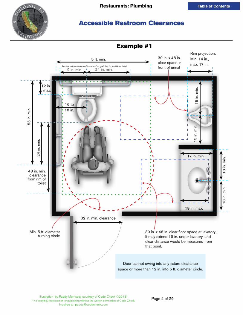
Accessible Restroom Clearances
Example #1
5 ft. min.Rim projection: Min. 14 in., maz. 17 in.
30 in. x 48 in. clear space in front of urinal12 in. min. 24 in. min.
Arrows below measured from end of grab bar to middle of toilet
16 to18 in.
12 in. max.
15 in
. min
.15
in. m
in.
18 in
. min
.18
in. m
in.
17 in. min.
19 in. max.
48 in. min.clearance
from rim of toilet
32 in. min. clearance
Min. 5 ft. diameter turning circle
24 in
. min
.
56
in. m
in.
Door cannot swing into any fixture clearancespace or more than 12 in. into 5 ft. diameter circle.
30 in. x 48 in. clear floor space at lavatory. It may extend 19 in. under lavatory, and clear distance would be measured from that point.

Page 5 of 29
Restaurants: Plumbing
Illustration by Paddy Morrissey courtesy of Code Check ©2013** No copying, reproduction or publishing without the written permission of Code Check.
Inquires to: [email protected]
Accessible Restroom Clearances
Example #215
in. m
in.
15 in
. min
.
5 ft.
min
18 in
. min
.
17 in. min.
19 in. max.
16–18 in.
24 in
. min
.
24 in. min.
54 in. min.
12 in
. min
.
12 in. min.
32 in. min. clearance
Door cannot swing into any fixture clearancespace or more than 12 in. into 5 ft. diameter circle.
30 in. x 48 in. clear space in front of urinal
Min. 5 ft. diameter turning circle
48 in. min.clearance
from rim of toilet
Arr
ows
are
mea
sure
d fro
m e
nd o
f gra
b ba
r to
mid
dle
of to
ilet
30 in. x 48 in. clear floor space at lavatory. It may extend 19 in. under lavatory, and clear distance would be measured from that point.

Page 6 of 29
Restaurants: Plumbing
Illustration by Paddy Morrissey courtesy of Code Check ©2013** No copying, reproduction or publishing without the written permission of Code Check.
Inquires to: [email protected]
Accessible Restroom Clearances
All dispensers max. 40 in. to
highest operable part
19 in. min.
Max. 44 in. from
operable control
17 in. max. to top of rim
7 in. min.9 in. max.
33–3
6 in
. ON
LY if
tank
toile
t
33 in., measured to center of grab bar
Flushcontrol
max. 44 in.
11/2 in. min. from top of tankto bottom of grab bar
17–19 in.
42 in. min.
14 in. min.
24 in. min.
54 in. min.
12 in. max. to wall
Grab bars: Diameter = 11/4–11/2 in.
Clearance from wall = 11/2 in.

Page 7 of 29
Restaurants: Plumbing
Illustration by Paddy Morrissey courtesy of Code Check ©2013** No copying, reproduction or publishing without the written permission of Code Check.
Inquires to: [email protected]
Accessible Restroom Clearances
17 in. min.
8 in. min.Knee ClearanceToe Clearance*
6 in. max.
9 in. min.
34 in. max.
29 in. min.
27 in. min.
* If a minimum of 9 in. toe height is provided, a maximum of 6 inches of the 48 inches clear floor space is required at the fixture may extend into the toe space.
Page 8 of 29
Restaurants: Plumbing
Illustration by Paddy Morrissey courtesy of Code Check ©2013** No copying, reproduction or publishing without the written permission of Code Check.
Inquires to: [email protected]
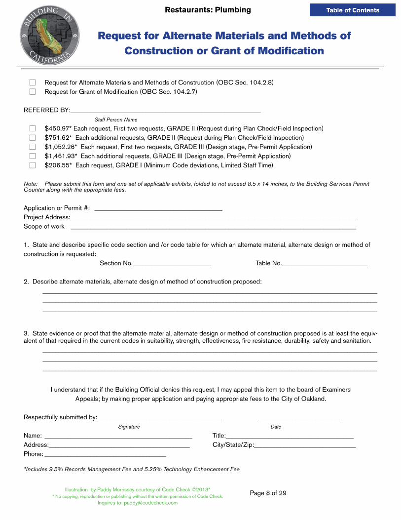
☐ Request for Alternate Materials and Methods of Construction (OBC Sec. 104.2.8) ☐ Request for Grant of Modification (OBC Sec. 104.2.7)
REFERRED BY:__________________________________________________________ Staff Person Name
☐ $450.97* Each request, First two requests, GRADE II (Request during Plan Check/Field Inspection) ☐ $751.62* Each additional requests, GRADE II (Request during Plan Check/Field Inspection) ☐ $1,052.26* Each request, First two requests, GRADE III (Design stage, Pre-Permit Application) ☐ $1,461.93* Each additional requests, GRADE III (Design stage, Pre-Permit Application) ☐ $206.55* Each request, GRADE I (Minimum Code deviations, Limited Staff Time)
Note: Please submit this form and one set of applicable exhibits, folded to not exceed 8.5 x 14 inches, to the Building Services Permit Counter along with the appropriate fees.
Application or Permit #: _______________________________________ Project Address: _______________________________________________________________________________________ Scope of work _______________________________________________________________________________________
1. State and describe specific code section and /or code table for which an alternate material, alternate design or method of construction is requested: Section No.________________________ Table No.__________________________
2. Describe alternate materials, alternate design of method of construction proposed: ______________________________________________________________________________________________________
______________________________________________________________________________________________________ ______________________________________________________________________________________________________
3. State evidence or proof that the alternate material, alternate design or method of construction proposed is at least the equiv-alent of that required in the current codes in suitability, strength, effectiveness, fire resistance, durability, safety and sanitation.
______________________________________________________________________________________________________ ______________________________________________________________________________________________________ ______________________________________________________________________________________________________
I understand that if the Building Official denies this request, I may appeal this item to the board of ExaminersAppeals; by making proper application and paying appropriate fees to the City of Oakland.
Respectfully submitted by:______________________________________ _________________________ Signature Date
Name: _____________________________________________ Title:_______________________________________Address:___________________________________________ City/State/Zip:_______________________________Phone: _____________________________________
*Includes 9.5% Records Management Fee and 5.25% Technology Enhancement Fee
Request for Alternate Materials and Methods of Construction or Grant of Modification

Page 9 of 29
Restaurants: Plumbing
Illustration by Paddy Morrissey courtesy of Code Check ©2013** No copying, reproduction or publishing without the written permission of Code Check.
Inquires to: [email protected]
704.3 Pot sinks, scullery sinks, dishwashing sinks, silverware sinks, commercial dishwashing machines, silver-ware-washing machines, and other similar fixtures shall be collected directly to the drainage system. A floor drain shall be provided adjacent to the fixture, and the fixture shall be connected on the sewer side of the floor drain trap, provided that no other drainage line is connected between the floor drain waste connection and the fixture drain. The fixture and floor drain shall be trapped and vented as required by this code.
411.2 Location of Floor Drains. Floor drains shall be installed in the following areas:
411 .2.1 Toilet rooms containing two (2) or more water closets or a combination of one (1) water closet and one (1) urinal, except in a dwelling unit.
411 .2.2 Commercial kitchens and in accordance with Section 704.3.

Illustration by Paddy Morrissey courtesy of Code Check ©2013** No copying, reproduction or publishing without the written permission of Code Check.
Inquires to: [email protected]
Page 10 of 25
Restaurants: Plumbing
PLUMBiNG APPLiANCe, APPURTeNANCe OR FiXTUReMiN. SiZe
TRAP & TRAP ARM7
PRiVATe PUBLiC ASSeMBLY8
Bathtub or combination Bath/ Shower 1-1/2 in. 2.0 2.0Bidet 1- 1/4 in. 1.0Bidet 1-1/2 in. 2.0Clothes Washer, domestic, standpipe5 2 in. 3.0 3.0 3.0Dental unit, cuspidor 1-1/4 in. 1.0 1.0Dishwasher, domestic, with independent drain2 1-1/2 in. 2.0 2.0 2.0Drinking Fountain of Water Cooler 1-1/4 in. 0.5 0.5 1.0Food Waste Grinder commercial 2 in. 3.0 3.0 3.0Floor Drain, emergency 2 in. 0.0 0.0Floor Drain (for additional sizes, see Section 702) 2 in. 2.0 2.0 2.0Shower, single head trap 2 in. 2.0 2.0 2.0Multi-head, each additional 2 in. 1.0 1.0 1.0Lavatory, single 1-1/4 in. 1.0 1.0 1.0Lavatory, in sets of 2 or 3 1-1/2 in. 2.0 2.0 2.0Washfountain 1-1/2 in. 2.0 2.0Washfountain 2 in. 3.0 3.0Mobile home trap9 3 in. 12.0Receptor, indirect waste1,3 1-1/2 in. See footnotes 1 & 3Receptor, indirect waste1,4 2 in. See footnotes 1 & 4Receptor, indirect waste1 3 in. See footnote 1
SiN
KS
Bar 1-1/2 in. 1.0Bar2 1-1/2 in. 2.0 2.0Clinical 3 in. 6.0 6.0Commercial with food waste2 1-1/2 in. 3.0 3.0Special purpose2 1-1/2 in. 2.0 3.0 3.0Special purpose 2 in. 3.0 4.0 4.0Special purpose 3 in. 6.0 6.0Kitchen, domestic2
(with or without waste food grinder and/or dishwasher)1-1/2 in. 2.0 2.0 2.0
Laundry2 (with or without discharge from a clothes washer) 2 in. 3.0 3.0Service or Mop Basin 2 in. 3.0 3.0Service or Mop Basin 3 in. 3.0 3.0Service, flushing rim 3 in. 6.0 6.0Wash, each set of faucets 2.0 2.0
Urinal, integral trap 1.0 GPF2 2 in. 2.0 2.0 5.0Urinal, integral trap > 1.0 GPF 2 in. 2.0 2.0 6.0Urinal, exposed trap2 1-1/2 in. 2.0 2.0 5.0Water Closet, 1.6 GPF gravity tank6 3 in. 3.0 4.0 6.0Water Closet, 1.6 GPF flushometer tank6 3 in. 3.0 4.0 6.0Water Closet, 1.6 GPF flushometer valve6 3 in. 3.0 4.0 6.0Water Closet >1.6 GPF gravity tank6 3 in. 3.0 6.0 8.0Water Closet > 1.6 GPF flushometer valve6 3 in. 4.0 6.0 8.0
1. Indirect waste receptors shall be sized based on the total drainage capacity of the fixtures that drain therein to, in accordance with Table 7-4.2. Provide a two (2) inch minimum drain.3. For refrigerators, coffee urns, water stations, and similar low demands.4. For commercial sinks, dishwashers and similar moderate, or heavy demands.5. Buildings having a clothes-washing area with clothes washers in a battery of three (3) or more clothes washers shall be rated at the six (6) fixture units each for purposes of sizing
commercial horizontal and vertical drainage piping. 6. Water closets shall be rated at six (6) fixture units when determining septic tank sizes based on Appendix K of this code.7. Trap sizes shall not be increased to the size where the fixture discharge may be inadequate to maintain their self-scouring properties.8. Assembly [Public Use (See Table 4-1)].9. [HDC2] for drainage unit fixture values related to the mobile home parks in all parts of the State of California, see California Code of Regulations Division 1, Chapter 2, Article 5,
Section 1268. For drainage unit fixture values related to special occupancy parks in all parts of the State of California, see California Code of Regulations Division 1, Chapter 2.2, Article 5, Section 2268.
Page 11 of 29
Restaurants: Plumbing
Illustration by Paddy Morrissey courtesy of Code Check ©2013** No copying, reproduction or publishing without the written permission of Code Check.
Inquires to: [email protected]
Fats, Oils and Grease (FOG) ControlGrease Control Device Requirements
1. introduction
When poured down the drain, Fats, Oils and Grease (FOG) may build up in pipes, pumps,and equipment, caus-ing significant problems in the community sewer collection system,including sanitary sewer line blockages that can lead to sanitary sewer overflows (SSO) that cause environmental and health hazards. East Bay Municipal Utility District(EBMUD) and the agencies in its wastewater service area, including the City of Oakland,developed a Region-al FOG Control Program for commercial food facilities. The primary goal of the FOG Control Program is to reduce the risk of blockages and SSOs in an effort to protect public health and the environment by minimizing public expo-sure to unsanitary conditions.
Food Service Establishments (FSE), and Food Manufacturing Facilities (FMF) in the City of Oakland are prohibited to discharge FOG to the sanitary sewer system. FSEs in the City of Oakland must install and maintain grease control devices (GCD), at the facility owner’s expense, to control FOG discharge from their facilities to the sanitary sewer system and not cause or contribute to FOG-related overflows, blockages or increased maintenance in the sanitary sewer system.
2. Definitions
• AUTOMATIC GREASE REMOVAL DEVICE: An automatic grease removal device (AGRD) is designed to re-tain FOG from the wastewater discharge. An AGRD automatically removes FOG from the wastewater stream and transfers it to an external container. AGRDs are typically installed inside and above ground.
• GREASE CONTROL DEVICE: A device used to remove and/or separate out FOG from kitchen wastes dis-charged to the community sewer, i.e. grease interceptor, grease trap or automatic grease removal device.
• GREASE INTERCEPTOR: A grease interceptor (GI) is a device designed to intercept FOG from the waste-water discharge. GIs include, but are not limited to,gravity GIs and other types of GIs that require cleaning/servicing by a pumping company due to design or per manufacturer’s specifications.
• HYDRO-MECHANICAL GREASE INTERCEPTOR (AKA: GREASE TRAP):Hydro-mechanical grease inter-ceptor (formerly named grease traps) treat kitchen wastewater from FSEs using gravity separation aided by vented flow control. They are typically installed indoors and connected to one to four sinks in the kitchen. They accumulate FOG and solids over time in a relatively small separator tank allowing the treated wastewater to discharge to the sanitary sewer.
• FOOD SERVICE ESTABLISHMENT: Any facility that prepares and/or serves food for commercial use or sale and that has a potential to discharge FOG into the collection system. This includes restaurants, cafes, lunch counters, cafeterias,hotels, hospitals, convalescent homes, factory or school kitchens, catering kitchens, baker-ies, grocery stores with food preparation and packaging, and meat cutting and preparation (excluding grocery stores with only food warming operations), meat packing facilities and other FSEs not listed above where FOG may be introduced into the community sewer system.
• FOOD MANUFACTURING FACILITY: Any facility that is licensed by the state that prepares food for commer-cial use or wholesale that has the potential to discharge FOG into the collection system. This includes com-mercial bakeries, chocolate factories, meat processing, etc. This shall include facilities not listed above where FOG may be introduced into the sewer system.
Selected list of approved GCDs can be found on page 8 and also at: www.ebmud.com/FOG
Page 12 of 29
Restaurants: Plumbing
Illustration by Paddy Morrissey courtesy of Code Check ©2013** No copying, reproduction or publishing without the written permission of Code Check.
Inquires to: [email protected]
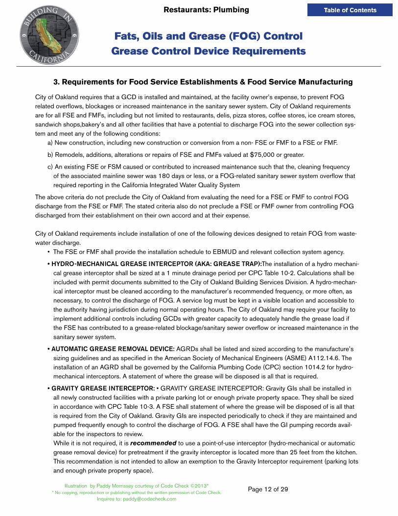
3. Requirements for Food Service establishments & Food Service Manufacturing
City of Oakland requires that a GCD is installed and maintained, at the facility owner’s expense, to prevent FOG related overflows, blockages or increased maintenance in the sanitary sewer system. City of Oakland requirements are for all FSE and FMFs, including but not limited to restaurants, delis, pizza stores, coffee stores, ice cream stores, sandwich shops,bakery’s and all other facilities that have a potential to discharge FOG into the sewer collection sys-tem and meet any of the following conditions:
a) New construction, including new construction or conversion from a non- FSE or FMF to a FSE or FMF.
b) Remodels, additions, alterations or repairs of FSE and FMFs valued at $75,000 or greater.
c) An existing FSE or FSM caused or contributed to increased maintenance such that the, cleaning frequency of the associated mainline sewer was 180 days or less, or a FOG-related sanitary sewer system overflow that required reporting in the California Integrated Water Quality System
The above criteria do not preclude the City of Oakland from evaluating the need for a FSE or FMF to control FOG discharge from the FSE or FMF. The stated criteria also do not preclude a FSE or FMF owner from controlling FOG discharged from their establishment on their own accord and at their expense.
City of Oakland requirements include installation of one of the following devices designed to retain FOG from waste-water discharge.
• The FSE or FMF shall provide the installation schedule to EBMUD and relevant collection system agency.
• HYDRO-MECHANICAL GREASE INTERCEPTOR (AKA: GREASE TRAP):The installation of a hydro mechani-cal grease interceptor shall be sized at a 1 minute drainage period per CPC Table 10-2. Calculations shall be included with permit documents submitted to the City of Oakland Building Services Division. A hydro-mechan-ical interceptor must be cleaned according to the manufacturer’s recommended frequency, or more often, as necessary, to control the discharge of FOG. A service log must be kept in a visible location and accessible to the authority having jurisdiction during normal operating hours. The City of Oakland may require your facility to implement additional controls including GCDs with greater capacity to adequately handle the grease load if the FSE has contributed to a grease-related blockage/sanitary sewer overflow or increased maintenance in the sanitary sewer system.
• AUTOMATIC GREASE REMOVAL DEVICE: AGRDs shall be listed and sized according to the manufacture’s sizing guidelines and as specified in the American Society of Mechanical Engineers (ASME) A112.14.6. The installation of an AGRD shall be governed by the California Plumbing Code (CPC) section 1014.2 for hydro-mechanical interceptors. A statement of where the grease will be disposed is all that is required.
• GRAVITY GREASE INTERCEPTOR: • GRAVITY GREASE INTERCEPTOR: Gravity GIs shall be installed in all newly constructed facilities with a private parking lot or enough private property space. They shall be sized in accordance with CPC Table 10-3. A FSE shall statement of where the grease will be disposed of is all that is required from the City of Oakland. Gravity GIs are inspected periodically to check if they are maintained and pumped frequently enough to control the discharge of FOG. A FSE shall have the GI pumping records avail-able for the inspectors to review. While it is not required, it is recommended to use a point-of-use interceptor (hydro-mechanical or automatic grease removal device) for pretreatment if the gravity interceptor is located more than 25 feet from the kitchen. This recommendation is not intended to allow an exemption to the Gravity Interceptor requirement (parking lots and enough private property space).
Fats, Oils and Grease (FOG) ControlGrease Control Device Requirements

Page 13 of 29
Restaurants: Plumbing
Illustration by Paddy Morrissey courtesy of Code Check ©2013** No copying, reproduction or publishing without the written permission of Code Check.
Inquires to: [email protected]
4. installation• FSEs shall receive approval from the City of Oakland through the City’s plancheck process for the design and
sizing of the GCD.
• All GCDs shall be installed in accordance with the 2010 California Plumbing code and plan check procedures. All GCDs shall be installed per manufacturer’s instructions and specifications.
• The FSE shall provide the installation schedule to EBMUD and the City.
• For sizing and operation help, please visit the Plumbing and Drainage Institute at
http://pdionline.org/
5. Maintenance• HYDRO-MECHANICAL GREASE INTERCEPTOR (AKA: GREASE TRAP):.A hydro-mechanical interceptor
must be cleaned according to the manufacturer’s recommended frequency, or more often, as necessary, to prevent the pass through of FOG into the collection system. A service log must be kept in a visible location and accessible to the authority having jurisdiction during normal operating hours. The City of Oakland may re-quire your facility to implement additional controls including GCDs with greater capacity to adequately handle the grease load if the FSE contributes to a grease-related blockage/sanitary sewer overflow or increased maintenance in the sanitary sewer system.
• GREASE INTERCEPTOR: If the FSE selects a gravity GI and other types of GIs shall be maintained at a mini-mum frequency of once per three month period, or more frequently as necessary to ensure that the FSE dis-charge does not cause or contribute to a grease related collection system blockage resulting in maintenance requirements and/or a sewage spill. Gravity GIs are inspected periodically to check if they are maintained and pumped frequently enough to control the discharge of FOG. Inspectors will ask to see the gravity GI pumping records,including the dates that the GI was pumped and by what hauler. Have these records available for the inspectors to review.
• GRAVITY INTERCEPTORS AND HYDRO MECHANICAL INTERCEPTORS SHALL NEVER EXCEED 25% TOTAL VOLUME OF GREASE IN RELATION TO INTERCEPTOR SIZE
All other types of GCDs shall be maintained per manufacturer’s instructions and specifications or more frequently, as necessary, to control the discharge of FOG.
6. Best Management Practices
• As with any piece of equipment, proper maintenance and best management practices (BMP) will ensure a well functioning and long life to whichever device is installed. All greasy waste shall be scraped and disposed of in an approved manner before entering the sink/dishwasher. Your GCD should never be used to pour pots of grease or fryer grease into your drainage system. These systems are not designed to work that way. All solids shall be scraped and removed as well before entering your GCD. Solids turn into hydrogen sulfide gas and can damage piping, manholes and other structures downstream of you facility.
• Additives/Emulsifiers: the City prohibits the use any additives in the wastewater collection system by an FSE for the purpose of emulsifying or biologically/chemically treating FOG.
Fats, Oils and Grease (FOG) ControlGrease Control Device Requirements

Page 14 of 29
Restaurants: Plumbing
Illustration by Paddy Morrissey courtesy of Code Check ©2013** No copying, reproduction or publishing without the written permission of Code Check.
Inquires to: [email protected]
For a complete list of BMPs, please visit: www.ebmud.com/FOG
7. enforcement
The City of Oakland, as defined in Oakland Municipal Code (OMC) 13.08.150, and 13.08.160D, is authorized to en-force all GCD requirements. It should be noted that if your facility fails to comply with the GCD requirement and does not have appropriate grease control mechanisms in place, and if your facility is found to be a contributor to a grease related sanitary overflow, you may be may be found in violation of the Federal Clean Water Act and subject to fines up to $10,000.00 per day by the California Regional Water Quality Control Board.
Please do your part to protect your sewers and keep our bay clean!
For more information about grease control devices and FOG control issues, please go to the following web site: www.ebmud.com/FOG or call EBMUD’s Environmental Services Division at (510) 287-1651.
Fats, Oils and Grease (FOG) ControlGrease Control Device Requirements

Page 15 of 29
Restaurants: Plumbing
Illustration by Paddy Morrissey courtesy of Code Check ©2013** No copying, reproduction or publishing without the written permission of Code Check.
Inquires to: [email protected]
Fats, Oils and Grease (FOG) ControlGrease Removal Devices
eBMUD APPROVeD GReASe ReMOVAL DeViCeS
Manufacturer Web Site Product Name Technology
ADS http://www.ads-pipe.com/pdf/en/10567_Grease_Interceptor_04-08.pdf
Grease Interceptor
Gravity device, pump out of captured grease and sediment by a licensed grease hauler
Grease Removal Systems
http://www.greaseremovalsystems.com/ ECH20Coalescing plates device, automatic draw-off of captured grease to external container
Goslyn Environmental
Systemshttp://www.goslyn.ca Goslyn
Hydro-mechanical device, captured grease auto-matically drained to an external container
Green Turtle http://www.greenturtletech.com/ proceptor-pdi.php Proceptor
Gravity device, pump out of captured grease and sediment by a licensed grease hauler
Highland Tank http://www.highlandtank.com/HT-AGIHT PGI
Hydro-mechanical device, skimmer draws-off cap-tured grease and transfers to an external container
Gravity device, pump out of captured grease and sediment by a licensed grease hauler
International GRD, Inc.
http://www.internationalgrd.com/
20002500 IB
2500 IBP35005000
Hydro-mechanical device, captured grease auto-matically drained to an external container
Jay R Smith Mfg. Co.
http://www.jrsmith.com/ Grease+GuardHydro-mechanical device, skimmer draws-off cap-tured grease and transfers to an external container
Jensen Precast http://www.jensenprecast.comGrease
InterceptorGravity device, pump out of captured grease and sediment by a licensed grease hauler
Josam Co. http://www.josam.com/
GI200AHydro-mechanical device, captured grease auto-matically pumped to an external container
60100H - GRDHydro-mechanical device, captured grease auto-matically pumped to an external container
Schier Products
http://www.schierproducts.com/Grease%20Interceptors%20Great%20
Basin.htmlGreat Basin
Gravity device, pump out of captured grease and sediment by a licensed grease hauler
Thermaco
http://www.big-dipper.com/index.php Big DipperHydro-mechanical device, skimmer draws-off cap-tured grease and transfers to an external container
http://www.trapzilla.com/index.php TrapzillaGravity device, pump out of captured grease and sediment by a licensed grease hauler
Zurn http://www.zurn.com/Pages/ProductDe-tails.aspx?NodeKey=375968 Z1199
Hydro-mechanical device, captured grease auto-matically drained to an external container

Page 16 of 29
Restaurants: Plumbing
Illustration by Paddy Morrissey courtesy of Code Check ©2013** No copying, reproduction or publishing without the written permission of Code Check.
Inquires to: [email protected]
Automatic Grease Removal Device:How It Works
BUILDING SERVICES DEPARTMENT250 Frank H. Ogawa Plaza, 2nd Floor, Oakland, CA 94612Inspection Services: 510.238.3443 FAX: 510.238.2263
Grease Removal Device (Automatic)
* No copying, reproduction or publishing without the written permission of Code Check. Inquires to: [email protected]
Illustration by Paddy Morrissey courtesy of Code Check ©2013*
Inlet Outlet
Greasy effluent rises through strainer
Skimming wheel assembly
Heating element
Wiper bladeassembly Timer / Motor / Electrical Enclosure
Grease skimmed off top & emptied through grease outlet
Solids evacuated to outlet flow
Effulent flowClean water
flow
Automatic Grease Interceptor
Grease rises to top
Solids sink to bottom
Whichever Grease removal device is chosen, it is important to keep solids out of the device as much as possible. Decomposing solids can create hydrogen sulfide gas that can corrode piping and concrete manhole structures. It is also important to note that dishwashers shall not discharge through a grease interceptor and Commercial Garbage grinders are PROhiBiTeD from being installed in the city. Only residential garbage disposers, that are installed in dwelling units are allowed.
Automatic Grease Removal Device Example, “Big Dipper”

Page 17 of 29
Restaurants: Plumbing
Illustration by Paddy Morrissey courtesy of Code Check ©2013** No copying, reproduction or publishing without the written permission of Code Check.
Inquires to: [email protected]
Gravity Grease Interceptor
Gravity Interceptors (GI) work on the “buoyancy” principle. As grease laden waste enters, the grease rises to the top of the interceptor. Interceptors are larger in size than other devices because they are tested and listed with a 30-minute retention time (the amount of time it takes the grease to rise to the top) GI’s are the required device when there is ample room on the property to install them. GI’s installed in parking lots shall include Hs20 loading rings and covers. Sample boxes are also available but not required. They do make it easier to check the level of grease in the GI and shall be a minimum 10” in depth. GI’s shall never exceed 25% capacity in grease. They must be pumped out by a licensed grease hauler. Entire Kitchens, including floor drains, pot sinks, hand washing sink, mop sinks, soup kettles, and food prep sinks equipped with solids strainer at the floor sink may drain through the GI. Commercial Grinders are NOT approved in the City of Oakland and an engineering justification by a licensed California Engineer, must be submitted for approval prior to the installation and approval of the underground plumbing if a dishwasher is designed to discharge through the GI. NOTE: Dishwasher effluent is rich in detergents and sanitizing chemicals which, when coupled with hot water, readily emulsify fats, oils
and grease components. This means the separated and trapped grease within a grease separator is lost to emulsification.
Avoid high detergent fixtures• Provide easy access for cleaning• Check for local required interceptor requirements
4 in. pipe & fittings standard
iNLeT OUTLeT
Outlet must be vented
Cast iron frames & covers with gasket
3 in., 6 in. & 12 in. grade rings as required
example of a 500-Gallon Gravity Grease interceptor
4 ft.
10
in.
4 ft.
7 in
.
5 ft.
10
in.
2 ft.
– 7
ft.

Page 18 of 29
Restaurants: Plumbing
Illustration by Paddy Morrissey courtesy of Code Check ©2013** No copying, reproduction or publishing without the written permission of Code Check.
Inquires to: [email protected]
Hydro-mechanical Grease Interceptor
Example of a Hydro-mechanical Grease Interceptor
Flow control device
Air intake
VentInlet baffle slows water flow
inlet
Outlet
Flow hits ramp directing grease and water upward
Diffuser baffle
Grease retention area
As air enters through the flow control intake, bubbles are created that attract to the grease. The grease bubbles help the buoyancy to get the grease to the top as quickly as possible. Oakland requires a service contract with a licensed grease hauler and a service log kept on site. Grease related Sanitary Sewer Overflows can subject the contributor to $10,000 a day fines for illicit discharges, and are violations of the EPA Clean Water Act of 1973. These units must be serviced regu-larly. Oakland also requires that the sizing of Hydro-Mechanical interceptors be in accordance with table 10-2 of the CPC using a 1 minute drainage period. Units sized using the 2 minute method will be denied.

Page 19 of 29
Restaurants: Plumbing
Illustration by Paddy Morrissey courtesy of Code Check ©2013** No copying, reproduction or publishing without the written permission of Code Check.
Inquires to: [email protected]
WhY DO We NeeD FOG ReQUiReMeNTS?
SiZiNG GReASe iNTeRCePTORS:
Under sizing can be a problem
• Increased drain down time
• More frequent cleaning
Fats, Oils & Grease (FOG) Requirements
Saturated fatty acids reacting with Calcium, forming a soft, tacky substance.
Free fatty acids harden with iron oxide, then chemically bond to the interior of the pipes.
FOG breaks down into Fatty acids and Glycerin
• Hydrolysis
• Microbes
• Chemicals
• Polar Hydrocarbon
• Chemicals
FOG/Food breaks down into:
• Sulfur reducing anaerobic bacteria
• Hydrogen sulfide
• Symbiotic aerobic bacteria
• Sulfuric acid
Over sizing can be a problem, too
• Increased cost of cleaning
• Over sizing encourages less frequent cleaning
• Less water exchange, septic conditions, low Ph.
Free fatty acids
• Fatty acids are corrosive
• Saturated fatty acids react with Calcium and form a solid tacky substance
• Hardens with Iron oxide
• Chemically bond to pipes
Photos courtesy of ASPE, Plumbing & Drainage Institute

Page 20 of 29
Restaurants: Plumbing
Illustration by Paddy Morrissey courtesy of Code Check ©2013** No copying, reproduction or publishing without the written permission of Code Check.
Inquires to: [email protected]
Automatic Grease Removal Devices with Internal & External Flow Control
Automatic Grease removal devices usually include a flow control (internal or external) a heater and skimming device. The skimmer will remove the grease layer and dispose it into an external container. Once that container is full, it needs to be emptied into the sites tallow can. Only licensed haulers are allowed to remove and dispose of the tallow can contents.
All three compartment sinks must be plumbed directly as shown in the drawings. A floor drain is required on the down-stream side of the Grease Removal Device

Page 21 of 29
Restaurants: Plumbing
Illustration by Paddy Morrissey courtesy of Code Check ©2013** No copying, reproduction or publishing without the written permission of Code Check.
Inquires to: [email protected]
Hydro-mechanical Interceptor Located Underfloor with External Flow Control
The picture depicts a standard Hydro-mechanical interceptor in the floor. The Flow control must remain accessible for service. The purpose of the flow control is to reduce turbulence through the interceptor and intake (entrain) air causing bubbles that attracts the grease, helping it rise to the top of the interceptor. Hydro-mechanical interceptors also work on the buoyancy principle as well as air entrainment.

Page 22 of 29
Restaurants: Plumbing
Illustration by Paddy Morrissey courtesy of Code Check ©2013** No copying, reproduction or publishing without the written permission of Code Check.
Inquires to: [email protected]
Type ll hoods are required over
high and low temperature commercial dishwashers.
Water vapor released is the same for high and low
temperature machines.
Exceptions:• Under counter
machines&
• Machines with vapor recovery
12 × 12 Floor Sink
Vent
Trap
Commercial Dishwasher
All stand up dishwashers require type ll hoods unless a vapor recovery unit is supplied. These dishwasher will lock and not allow the user to open until all water, condensate and vapor has been removed through the drain. All dish washers shall have a solids removal tray a drain indirectly to the sewer.

Page 23 of 29
Restaurants: Plumbing
Illustration by Paddy Morrissey courtesy of Code Check ©2013** No copying, reproduction or publishing without the written permission of Code Check.
Inquires to: [email protected]
2 Compartment Food Prep Sinkwith Indirect Drain
Vent
Trap
12 X 12 Floor Sink
Food prep sinks do not drain through an interceptor unless it is through a Gravity Interceptor. Food Prep sinks shall discharge through an indirect drain to the sewer to prevent potential contamination of food in the event of a sewer back-up

Page 24 of 29
Restaurants: Plumbing
Illustration by Paddy Morrissey courtesy of Code Check ©2013** No copying, reproduction or publishing without the written permission of Code Check.
Inquires to: [email protected]
Backflow Devices for Carbonated Beverages & Espresso Machines - 2 Examples
http://www.watts.com/pages/_products_details.asp?pid=6890
LFN9, LFN9CLead Free* Dual Check Vacuum Breakers
SD-3Dual Check Valves with Atmospheric Port & Strainer for Carbonated Beverage Machines
http://www.watts.com/pages/_products_details.asp?pid=891
Page 25 of 29
Restaurants: Mechanical
Illustration by Paddy Morrissey courtesy of Code Check ©2013** No copying, reproduction or publishing without the written permission of Code Check.
Inquires to: [email protected]
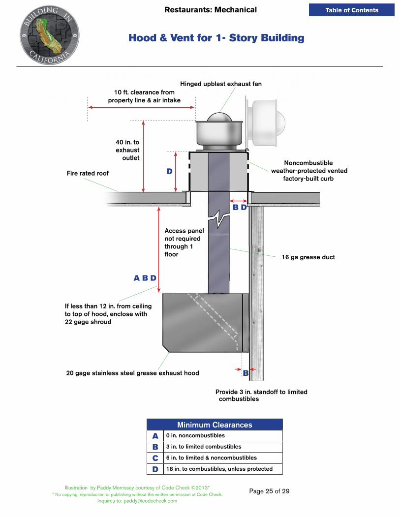
Hood & Vent for One-Story Building
Hinged upblast exhaust fan10 ft. clearance from
property line & air intake
40 in. to exhaust
outlet
D
B D
B
16 ga grease duct
Access panel not required through 1 floor
If less than 12 in. from ceiling to top of hood, enclose with 22 gage shroud
Fire rated roof
20 gage stainless steel grease exhaust hood
Provide 3 in. standoff to limited combustibles
A B D
Noncombustible weather-protected vented
factory-built curb
Minimum ClearancesA 0 in. noncombustibles
B 3 in. to limited combustibles
C 6 in. to limited & noncombustibles
D 18 in. to combustibles, unless protected
city of oaklandBUILDING SERVICES
ALL ILLUSTRATIONS ©2012 CODE CHECK
Hood & Vent for 1- Story Building

Page 26 of 29
Restaurants: Mechanical
Illustration by Paddy Morrissey courtesy of Code Check ©2013** No copying, reproduction or publishing without the written permission of Code Check.
Inquires to: [email protected]
Hood & Vent for Two-Stories or More
Hinged upblast exhaust fan
10 ft. min. clearance from property line & air intake
Weather-protected opening
Vented shaft
1 hour shaft
2 hour shaft required if penetrating 3 floors
40 in. min. to exhaust
outlet
D D
C
Duct access panel required at each floor
Fire-rated floor
22 ga stainless flashing, sealed around grease duct at this point because of fire rated floor
16 ga grease duct
Roof
20 ga stainless steel grease exhaust hood
Opening in fire-rated shaft(not required in single story)
Grease duct
city of oaklandBUILDING SERVICES
A B D
BProvide 3 in. standoff to limited combustibles
Minimum ClearancesA 0 in. noncombustibles
B 3 in. to limited combustibles
C 6 in. to limited & noncombustibles
D 18 in. to combustibles, unless protected
ALL ILLUSTRATIONS ©2012 CODE CHECK
If less than 12 in. from ceiling to top of hood, enclose with 22 gage shroud
Hood & Vent for 2- Story Building

Page 27 of 29
Restaurants: Mechanical
Illustration by Paddy Morrissey courtesy of Code Check ©2013** No copying, reproduction or publishing without the written permission of Code Check.
Inquires to: [email protected]
Hood, Duct & Shaft
Min. rise on horizontal duct ¼ “ per ft. up to 75 ft.
Max. 48 in.
16 ga grease duct
Opening in fire-rated shaft
Opening in fire-rated shaftOpening in fire-rated shaft
Duct access panel
Duct access panelDuct access panel
20 gage stainless steel grease exhaust hood
Distance between cleanouts on horizontal duct Max 12 ft.
Horizontal duct over 75 ft. shall have a 1 in. per ft. graded back toward the hood
Page 28 of 29
Restaurants: Mechanical
Illustration by Paddy Morrissey courtesy of Code Check ©2013** No copying, reproduction or publishing without the written permission of Code Check.
Inquires to: [email protected]
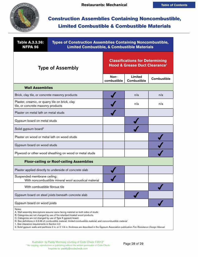
Table A.3.3.36:NFPA 96
Types of Construction Assemblies Containing Noncombustible, Limited Combustible, & Combustible Materials
Type of AssemblyClassifications for Determining Hood & Grease Duct Clearance1
Non- combustible
Limited Combustible Combustible
Wall Assemblies
Brick, clay tile, or concrete masonry products 4 n/a n/a
Plaster, creamic, or quarry tile on brick, clay tile, or concrete masonry products 4 n/a n/a
Plaster on metal lath on metal studs 4Gypsum board on metal studs 4Solid gypsum board2 4Plaster on wood or metal lath on wood studs 4Gypsum board on wood studs 4Plywood or other wood sheathing on wood or metal studs 4 Floor-ceiling or Roof-ceiling Assemblies
Plaster applied directly to underside of concrete slab 4 Suspended membrane ceiling: With noncombustible mineral wool acoustical material 4 With combustible fibrous tile 4Gypsum board on steel joists beneath concrete slab 4Gypsum board on wood joists 4Notes:A. Wall assembly descriptions assume same facing material on both sides of studs.B. Categories are not changed by use of fire-retardant-treated wood products.C. Categories are not changed by use of Type X gypsum board.D. See definitions in 3.3.36 of combustible material, limited-combustible material, and noncombustible material1. See clearance requirements in Section 4.2 2. Solid gypsum walls and partitions 2 in. or 2 1/4 in. thickness are described in the Gypsum Association publication Fire Resistance Design Manual
Construction Assemblies Containing Noncombustible,
Limited Combustible & Combustible Materials

Page 29 of 29
Restaurants: Mechanical
Illustration by Paddy Morrissey courtesy of Code Check ©2013** No copying, reproduction or publishing without the written permission of Code Check.
Inquires to: [email protected]
Acceptable Welds for Grease DuctsFor Type l Hoods
Based on NFPA 96 standards
Bell Duct Joint Telescoping Duct Joint
Exhaust duct Exhaust duct
Exhaust ductExhaust duct
Male end
Inside section
Outside section
16 gauge (1/16 in.)black iron
Weld aroundcompletely
Weld aroundcompletely
Weld aroundcompletely
Weld aroundcompletely
Weld aroundcompletely
Weld aroundcompletely
Weld aroundcompletely
I.D. (in.) I.D. (in.)
I.D. (in.)
I.D. (in. + 1/4 in. max.)
I.D. (in. + 1/4 in. max.)
Female end
2 in. max. 2 in. max.
NOTES:1. Duct size and gage shall be the same throughout the duct system.2. Smaller (inside) male duct end is always above or uphill (on sloped duct), to be self-draining into larger
(outside) female duct end.