restore-l satellite servicing internship final report ... · nasa ksc – internship final report...
TRANSCRIPT

NASA KSC – Internship Final Report
Kennedy Space Center 1 12 April 2019
Restore-L Satellite Servicing Internship Final Report Giovanni Campos
Kennedy Space Center
Major: Mechanical Engineering Technology
NASA Internships and Fellowships (NIFS), Spring Session
Date: 12 April 2019
https://ntrs.nasa.gov/search.jsp?R=20190002681 2020-05-07T23:58:05+00:00Z
NASA KSC – Internship Final Report
Kennedy Space Center 2 12 April 2019
Restore-L Satellite Servicing Internship Final Report
Giovanni A. Campos1
NASA Kennedy Space Center, FL 32899
Nomenclature
PTS = Propellant Transfer Subsystem
NASA = National Aeronautics and Space Administration
EDO = Engineering Development & Operations facility
NIFS = NASA Interns, Fellows, and Scholars
CAD = Computer-Aided Design
CNC = Computer-Numerical-Control
ACCLLP = Apollo Challenger Columbia Lessons Learned Program
lbf = Pound-Force
𝑃 = Pressure
f = Pipe Friction Coefficient
L = Length of pipe
Di = Inner Diameter
𝜌 = Density
𝜔 = Flow velocity
Abstract
This paper reviews the Restore-L mission purpose and the necessary research and
simulations to meet mission specification for the Propellant Transfer Subsystem (PTS). It is
essential the PTS undergoes functionality testing, environmental testing, and calculations to
understand the capabilities of the system. For the testing of components from PTS, a proper
test setup is required. It is vital for test hardware, such as hoses and valves, to stay in place
while the test is being performed. For the test hardware to operate correctly, positioning,
orientation, and alignment are critical as well. In addition to the testing, calculations for
pressure drop were explored. To meet requirements for test setups, designs for test
hardware mounts were sketched, 3D modeled, and manufactured. Using fluid mechanics for
calculations, a pressure drop equation was applied with known variables from mission
specification. With the test hardware mounts designed and manufactured, the test setup was
assembled with mounts installed. Test hardware mounts met all design requirements.
Calculation for pressure drop were concluded and an answer was achieved. Meeting design
requirement, mission specification, and calculating correct results allow the Restore-L
mission to make further progress and help understand the effectiveness of the Propellant
Transfer Subsystem.
______________________________
1 NIFS Intern, Exploration Payloads Branch (NE-L5), Kennedy Space Center. Educational Institution: CUNY New
York City College of Technology

NASA KSC – Internship Final Report
Kennedy Space Center 3 12 April 2019
I. Introduction
atellites have a crucial role in science when it comes to observing weather, measuring greenhouse gases, or
studying stars. But all satellites have a lifespan, depending on how much propellant they have left. When a
satellite is about to be decommissioned, engineers can use the last of its propellant to make one of two choices. The
first choice is to send it back to earth, where the re-entry will burn up the satellites. Any surviving debris will land in
the spacecraft cemetery located in the Pacific Ocean. The second choice is to send it farther into space, into a
graveyard orbit [1]. With the Restore-L mission comes a third choice of refueling a live satellite to prolong its
lifespan, even if the satellite was not designed to be serviceable. Restore-L will be a “robotic spacecraft equipped
with the tools, technologies and techniques” that are necessary to complete this mission. To complete this goal, there
are five key elements that need to be researched, designed, and tested. Those key elements are: 1) Autonomous,
Real-Time Relative Navigation System, 2) Servicing Avionics, 3) Dexterous Robotic Arms, 4) Advanced Tool
Drive and Tools, and 5) Propellant Transfer Subsystem. This paper will be focused on the Propellant Transfer
Subsystem.
The Propellant Transfer Subsystem (PTS) is one of the key elements to bring the Restore-L mission to life. The
system needs to transfer propellant to the satellite “at the right temperature, pressure, and rate” [2]. In order to
achieve these requirements, functionality testing, environmental testing, and calculations involving fluid mechanics
need to be completed. These tests and calculations are performed to simulate what the system will be going through
in outer space during its mission.
Outside of the Restore-L mission, an additional task was completed for the internship. This task included the
website development for the Apollo Challenger Columbia Lessons Learned Program (ACCLLP).
II. Functionality Test
A. Purpose
The functionality test that was performed for PTS was a tensile test on a flex hose. The purpose of the tensile
test was to determine if a custom made ¼ inch metal braided convoluted flex hose would plastically deform under
static loading. The objective was to certify no plastic deformation at a weight of 200 lbf or less. Any weight above
200 lbf was for reference only.
B. Preparations
A quality check on the flex hose, length measurement method preparations, and the test setup were all essential
for the preparation of this test.
The quality check was to detect any and all
abnormalities on the flex hose that included, but was not
limited to, dings on the steel braid, over/under weaving
pattern mistakes, tear of a single/multiple steel braid(s),
misalignment of the outer and inner braids, etc. Any of these
abnormalities could have affected the results of the tensile
test, which was why these abnormalities needed to be noted
before the test was conducted. As seen in fig. 1, a section of the flex hose shows marked abnormalities with yellow
tape. The most common abnormalities were minor dings on the steel braid.
Continuing with the preparation of the test, the length
measurement procedure was also arranged. A string was
added to the flex hose as a reference for original length and
a piece of tape marked off the end of that length, as seen in
fig. 2. While the flex hose would stretch due to tension, the
string would be unaffected by the load, keeping its original
length.
S
Figure 1. Quality Check of the Flex Hose.
Image Credit: Giovanni Campos, NIFS Intern.
Figure 2. String and Tape Datum. Image Credit:
Giovanni Campos, NIFS Intern.

NASA KSC – Internship Final Report
Kennedy Space Center 4 12 April 2019
The test setup was constructed using various items in the Engineering Development & Operations facility
(EDO), such as, a step ladder, insulation foam, rope, and a wooden platform. Safety was incorporated into the test
setup by covering all opening of the step ladder with
insulation foam. In the circumstances the flex hose were to
fail under static loading, any debris would have been
contained within the setup.
One free end of the flex hose, attached with a kellem,
was mounted to the top of the step ladder, while the other
free end, also attached with a kellem, was mounted with the
wooden platform. The wooden platform was created to hold
the static load. 20 lbf and 50 lbf weights were used for the
testing procedure. Figure 3 shows the initial state of the test
before starting the procedure.
C. Procedure
When the test was performed, the starting load was
determined to be 80 lbf. To reach this load, extra weights
were applied to the wooden platform, which weighed 62.2
lbf, to reach 80 lbf. Next, the load was adjusted to 100 lbf
by adding a 20 lbf weight to the platform. From the 100 lbf
load, increments of 50 lbf weights were added to the
platform until a load of 450 lbf was achieved. Finally, a 100
lbf weight was added to the 450 lbf load to reach a final load
of 550 lbf.
The length of the flex hose was measured and recorded
for each loading and unloading of the weights. Two
methods were used to record the lengths of the flex hose.
The first was from collar-to-collar and the second was from Tape-Datum-to-collar. The second method used the
string attached to the flex hose, using the tape at the end of it as reference.
D. Results
Table 1 shows the final measurements under different loading and unloading throughout the test. A gradual
increase in length can be seen with each and every loading, but when unloaded, the length of the flex hose returned
to 31.688 in (collar-to-collar) and 0.031 in (Tape Datum).
Figure 3. Tension Test Setup. Image Credit: Brian
Nufer, NIFS Mentor.

NASA KSC – Internship Final Report
Kennedy Space Center 5 12 April 2019
The maximum length (from collar-to-collar) for loaded length measurement was 32.000 in at the maximum load
of 550 lbf. A gradual increase of the loaded length can be seen again in the graph from fig. 4. The initial unloaded
length of the flex hose, 31.688 in, was consistent throughout the duration of the test, until the maximum loading of
550 lbf, which had a final unloaded length of 31.750 in. This shows that the flex hose did not have a significant
change throughout the test.
Using the second method (from tape-datum-to-collar), a maximum elongation of 0.250 in was recorded for
loaded length. Again, a gradual increase in loaded length was noted as the test progresses in fig. 5. Once unloaded,
the recorded measurements showed a difference from the original length of the string to the length the flex-hose
returned to, which was 0.031 in. The initial unloaded length of the flex hose was 0.000 in, which also shows that the
flex hose did not have a significant change throughout the test, meeting mission specification.
Figure 5. Length of Flex-hose using Tape Datum Method.
Figure 4. Length of Flex-hose using tape measure (collar-to-collar).

NASA KSC – Internship Final Report
Kennedy Space Center 6 12 April 2019
III. Environmental Test
A. Purpose
The environmental test for the Restore-L mission is a depressurization test on a Restore-L component that
simulates the depressurization during launch. The test will be used to see how the effects of depressurization
affected the component.
B. Preparations
Test preparations involved manufacturing for the test hardware that were requisites for the test. Examples of
what was manufactured for test hardware were Teflon gaskets, a mounting platform, mounts for both a manual valve
and a solenoid valve, and a control box for the electronics. New Teflon gaskets were required for the pressure
vessel, manual valve, and solenoid valve flanges being employed to conduct the test. A mounting platform was
made to install a manual valve and a solenoid valve for the test setup. To operate correctly, it was necessary for the
manual valve to be held in place and in a 90 degree orientation, so mounts were designed to meet these design
requirements. Mounts for the solenoid valve followed the same design requirements, with an additional requirement
of having the mounts be adjustable in height. The adjustable height requirement was for ease of assembly, so the
fittings of the manual valve and solenoid valve can be aligned properly when installed. Finally, a control box that
holds the electronics for the test was also required to be manufactured.
C. Teflon Gaskets
Gaskets are placed in between the flanges of any pressurized component. For the purpose of this test, gaskets
were imperative for the pressure vessel, manual valve, and solenoid valve flanges. Cutouts were made using an 8 ft
x 4 ft Teflon sheet via waterjet.
It was determined that different sizes were desired for
each hardware. Using Creo (3D Modeling Software), a sketch
and design for the cutouts was conceptualized to expend as
much of the Teflon sheet as possible, while preserving any
reusable scrap. Figure 6 shows the layout of the cutouts using
the software. The circular shapes, highlighted in pink, were the
gaskets being implemented for the flanges. The square shapes,
also highlighted in pink, were what was preserved after the
manufacturing process.
After the Teflon layout was approved, the sketch file was
converted into a DXF file for the waterjet and a PDF (see
appendix 1) was made as a manufacturing reference.
The result from the waterjet are shown in fig. 7. Showing the three different sizes for the test setup. Figure 8
shows the gasket installed between two flanges from the manual valve.
Figure 6. Teflon gasket sketch. Image Credit:
Giovanni Campos, NIFS Intern.
Figure 7. Teflon cutout results.
Image Credit: Giovanni
Campos, NIFS Intern.
Figure 8. Teflon Gasket installed in
between flanges. Image Credit: Giovanni
Campos, NIFS Intern.
NASA KSC – Internship Final Report
Kennedy Space Center 7 12 April 2019
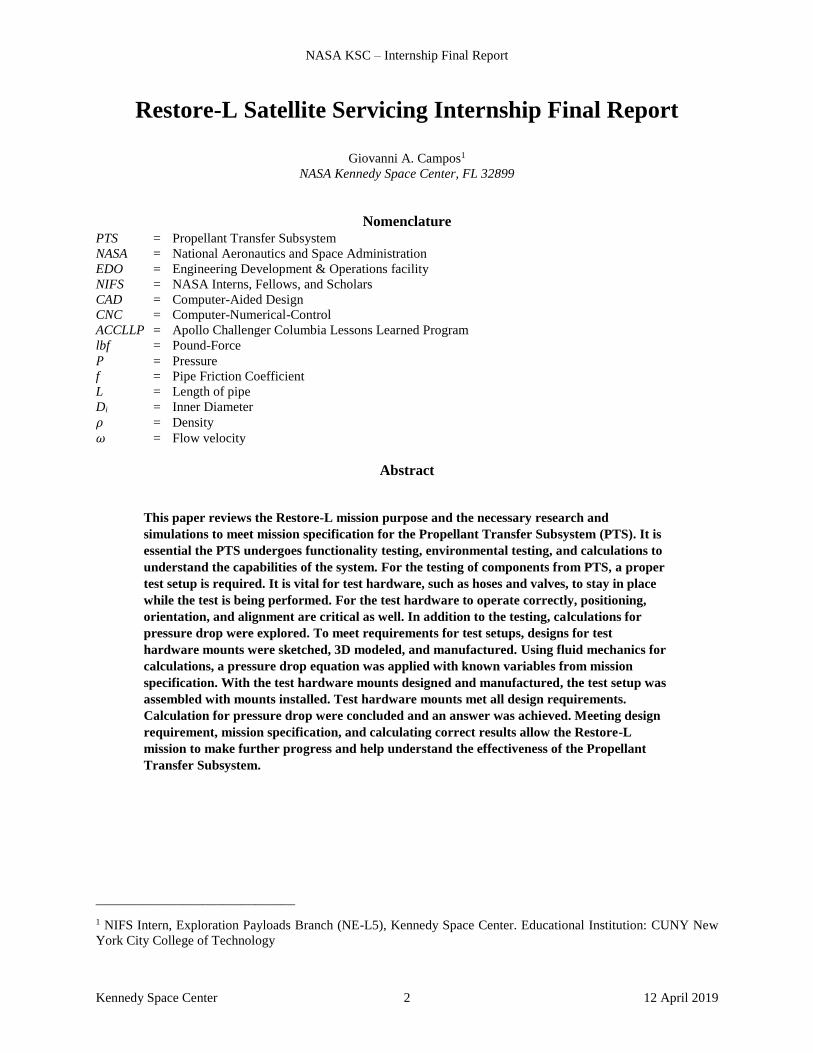
D. Mounting Platform
The mounting platform was a necessary application for the test setup. Designed for flexible placement and a
solid brace for the manual valve and solenoid valve mounts. The materials used for the platform was lumber 2x4 and
plywood.
Utilizing Autodesk Sketchable (Sketching Software), a sketch was finished to arrange the lumber 2x4 positions
to create the sturdy platform. The dimensions referenced in fig. 9 were to assist in placement for the mounts when
installed. Figure 10 shows the mounting platform installed with added legs to help with stability.
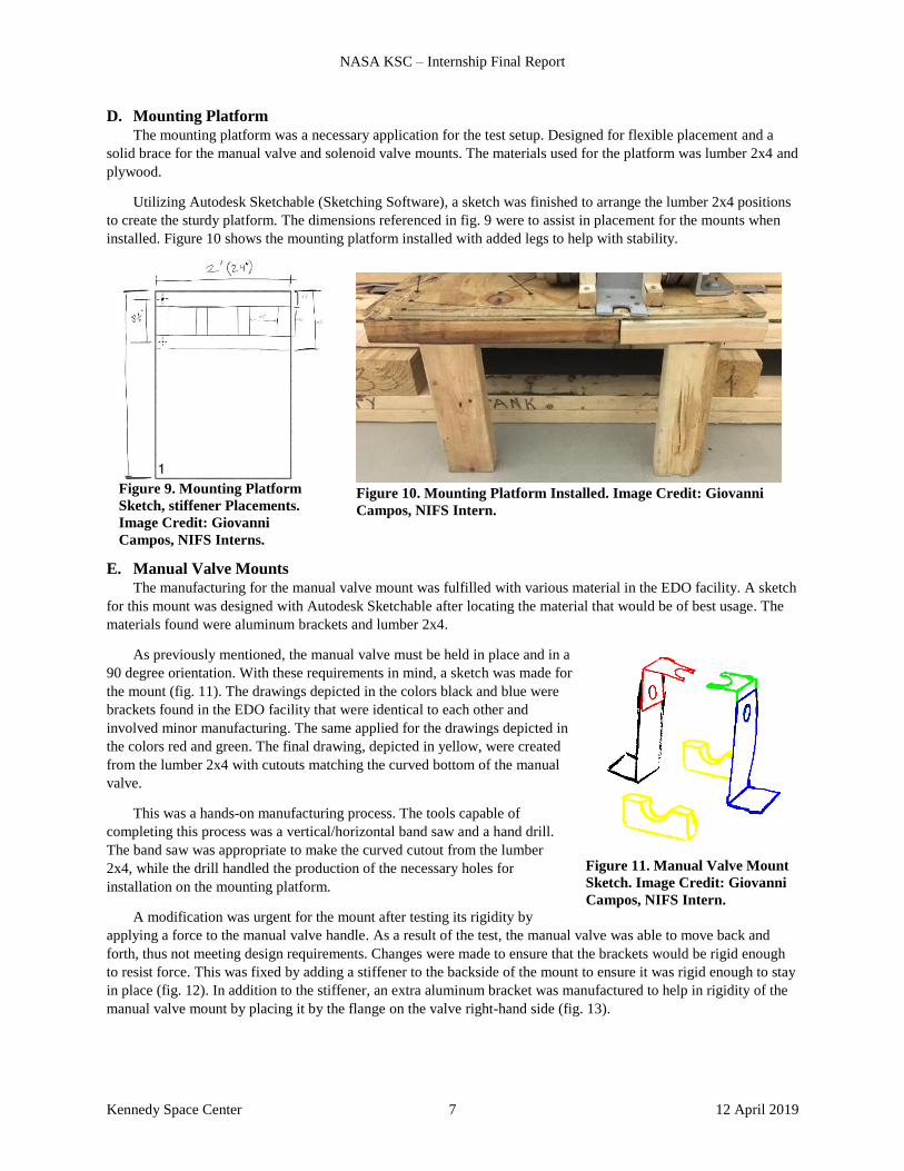
E. Manual Valve Mounts
The manufacturing for the manual valve mount was fulfilled with various material in the EDO facility. A sketch
for this mount was designed with Autodesk Sketchable after locating the material that would be of best usage. The
materials found were aluminum brackets and lumber 2x4.
As previously mentioned, the manual valve must be held in place and in a
90 degree orientation. With these requirements in mind, a sketch was made for
the mount (fig. 11). The drawings depicted in the colors black and blue were
brackets found in the EDO facility that were identical to each other and
involved minor manufacturing. The same applied for the drawings depicted in
the colors red and green. The final drawing, depicted in yellow, were created
from the lumber 2x4 with cutouts matching the curved bottom of the manual
valve.
This was a hands-on manufacturing process. The tools capable of
completing this process was a vertical/horizontal band saw and a hand drill.
The band saw was appropriate to make the curved cutout from the lumber
2x4, while the drill handled the production of the necessary holes for
installation on the mounting platform.
A modification was urgent for the mount after testing its rigidity by
applying a force to the manual valve handle. As a result of the test, the manual valve was able to move back and
forth, thus not meeting design requirements. Changes were made to ensure that the brackets would be rigid enough
to resist force. This was fixed by adding a stiffener to the backside of the mount to ensure it was rigid enough to stay
in place (fig. 12). In addition to the stiffener, an extra aluminum bracket was manufactured to help in rigidity of the
manual valve mount by placing it by the flange on the valve right-hand side (fig. 13).
Figure 11. Manual Valve Mount
Sketch. Image Credit: Giovanni
Campos, NIFS Intern.
Figure 9. Mounting Platform
Sketch, stiffener Placements.
Image Credit: Giovanni
Campos, NIFS Interns.
Figure 10. Mounting Platform Installed. Image Credit: Giovanni
Campos, NIFS Intern.

NASA KSC – Internship Final Report
Kennedy Space Center 8 12 April 2019
Once the changes were equipped, the manual valve was tested once more for a rigidity check. The design
requirements were meet in keeping the valve in place and in a 90 degree orientation. Figure 14 shows the Manual
Valve fully installed. Figure 15 shows an overhead of the manual valve mount, where it sits upright, perpendicular
to the ground.
Figure 12. Stiffener to backside of the mount.
Image Credit: Giovanni Campos, NIFS Intern.
Figure 13. Extra Bracket attached to the
Flange. Image Credit: Giovanni Campos,
NIFS Intern.
Figure 14. Manual Valve Mount. Image Credit:
Giovanni Campos, NIFS Intern.
Figure 15. Overhead of Manual Valve Mount.
Image Credit: Giovanni Campos, NIFS Intern.

NASA KSC – Internship Final Report
Kennedy Space Center 9 12 April 2019
F. Solenoid Valve Mounts
Similar to the process of the Manual Valve mount, the materials had to be located before a sketch could be
conceptualized. The materials found for the solenoid valve mount were steel brackets and an aluminum L-channel
Stock.
Following the same design requirements of the previous valve mount, with an additional requirement of having
the mounts be adjustable in height, a rough sketch was
designed. As seen in fig. 16, two assembled mounts will be
placed at either side of the solenoid valve. An assembled
mount consist of the top aluminum bracket, Solenoid Mount
A, and the bottom steel bracket, Solenoid Mount B. The
surface of Solenoid Mount A will act as a holder for the
solenoid valve. The curve cutout was made to match the
curved edges of the valve for ease of assembly. Solenoid
Mount B required no manufacturing and came with pre-
installed slots. Solenoid Mount B met with the adjustable
height design requirement.
Following the sketch, a 3D model (fig. 17) was created
for Solenoid Mount A and Solenoid Mount B. This was to
obtain exact dimensions and to better visualize the mounts.
A PDF of the full assembly (see Appendix 2) was made as a manufacturing reference.
The manufacturing process for Solenoid Mount A involved the aluminum L-channel stock. A PDF of the
dimensions (see Appendix 3) was made as a manufacturing reference. This required the use of the vertical/horizontal
band saw and hand drill.
When finally installed, the use of an insulation foam was needed to act as a foundation and to help properly
align the fitting of the solenoid valve to the manual valve. The mounts kept the solenoid valve from moving,
meeting design requirements. The final result of the Solenoid Valve mount is shown in fig. 18.
Figure 16. Solenoid Valve Mount Sketch. Image
Credit: Giovanni Campos, NIFS Intern.
Figure 17. Solenoid Valve Mount Creo.
Image Credit: Giovanni Campos, NIFS
Intern. Figure 18. Solenoid Valve Mount. Image
Credit: Giovanni Campos, NIFS Intern.

NASA KSC – Internship Final Report
Kennedy Space Center 10 12 April 2019
G. Control Box
The control box required two manufacturing processes. The first is for the box itself to hold the electronic
components in place. The second is a connector panel to hold a maximum of twelve 7-pin connector heads. The box
requires two slot cutouts for the connector panel, so the
connector heads can be accessible when mounted on to the
box, and a hole cutout to act as a passthrough for any
additional cables required for the electronic components.
Utilizing Creo, a Computer-Aided Design (CAD)
model was generated from the manufacturer of the junction
box, Hoffman A1412CH. Using the generated CAD model,
the slots were created on the backside of the box and the
hole passthrough was created on the right-hand surface from
the slots. The connector panel was also created in Creo using measurement of the 7-pin connector heads and the
newly created slots for the panel, as seen in fig. 19. Figure 20 shows the slots and hole design and placement relative
to the box. Figure 21 shows the full assembly of the control box and the connector panel.
The CAD models were later converted to the appropriate file required to be machined. The control box will be
milled out using a Computer-Numerical-Control (CNC) Milling Machine (STP file) and the connector panel will be
cut out on the waterjet (DXF file). PDFs of the control box general dimensions (see Appendix 4), slot dimensions
(see Appendix 5), the hole passthrough dimensions (see Appendix 6), and the connector panel dimensions (see
Appendix 7) were all made as a manufacturing reference.
IV. Pressure Drop Calculations
A. Purpose
To aid in the Restore-L mission, calculations in fluid mechanics were made using liquids, water and hydrazine.
Along with the calculation, the results can be confirmed with a simulation for water, but not for hydrazine. Although
similar in properties, hydrazine is dangerous and must be handled with care and safety in mind. For this reason,
water can be used as a substitute for hydrazine in a physical test.
B. Results
The following Equation was used to calculate pressure drop.
𝛿𝑃 = 𝑓 × 𝐿
𝐷𝑖 ×
𝜌
2 × 𝜔2 (1)
𝑃 = Pressure
f = Pipe Friction Coefficient
L = Length of pipe
Di = Inner Diameter
Figure 19. Connector Panel Creo. Image Credit:
Giovanni Campos, NIFS Intern.
Figure 20. Control Box with cutouts Creo. Image
Credit: Giovanni Campos, NIFS Intern. Figure 21. Control Box Assembly Creo. Image
Credit: Giovanni Campos, NIFS Intern.

NASA KSC – Internship Final Report
Kennedy Space Center 11 12 April 2019
𝜌 = Density
𝜔 = Flow velocity
With what is specified and given to follow mission requirements, the final calculations after using Eq. (1) for
water and hydrazine were, 1.6 𝑙𝑏
𝑖𝑛2 and 1.57 𝑙𝑏
𝑖𝑛2 respectively.
V. Website Development
A. Purpose
Apollo Challenger Columbia Lessons Learned Program (ACCLLP) is directed by Michael Ciannilli. The
purpose of this program is to gather all information on previous missions where tragedy struck. From every mistake
and accident, there are lessons to be learned. Lessons that also repeat themselves in missions several years apart.
This program increase awareness of past mistakes and can help prevent history from repeating itself. The task was to
help in the development and update the ACCLLP website content.
B. Progress
In order to assist in the development of this website, Sitecore training and research on the Apollo, Challenger,
and Columbia accidents were mandatory. Contents that were present, prior to my involvement, were modified,
cleaned up, and made consistent throughout the website. Apollo 13 and Challenger contents were added to their
respective pages to give more information on the purpose of the mission, the astronaut’s background, the lessons
learned from the tragedy, and the accident reports. Figure 22 shows an example of the home pages of the updated
content.
C. Future Work
A possible plan to help with the future work of this program is to gather as many volunteers as possible to
update the website and also increase the awareness of these lessons learned by having young and future engineers
contribute to the project.
VI. Conclusion
Simulating and understanding what the Propellant Transfer Subsystem will go through in outer space during its
mission is now possible, with the conclusion of the functionality test, the environmental test preparations secure, and
the answer to the pressure drop calculations solved. With the achievements of these tasks, the Propellant Transfer
Subsystem continues to make progress, bringing the Restore-L mission closer to a reality. Soon, a robotic spacecraft
will have the technology and ability to refuel current and future satellites, ending the decision of decommissioning
these satellites and prolonging their lives instead. Once this goal is reached, Restore-L will allow satellites to
continue functioning, gather new information on our planet, and study space for science.
Figure 22. Example of Home pages for ACCLLP, Apollo 13, and Challenger. Image
Credit: Giovanni Campos, NIFS Intern.

NASA KSC – Internship Final Report
Kennedy Space Center 12 12 April 2019
Appendix
Appendix 1

NASA KSC – Internship Final Report
Kennedy Space Center 13 12 April 2019
Appendix 2

NASA KSC – Internship Final Report
Kennedy Space Center 14 12 April 2019
Appendix 3

NASA KSC – Internship Final Report
Kennedy Space Center 15 12 April 2019
Appendix 4

NASA KSC – Internship Final Report
Kennedy Space Center 16 12 April 2019
Appendix 5

NASA KSC – Internship Final Report
Kennedy Space Center 17 12 April 2019
Appendix 6

NASA KSC – Internship Final Report
Kennedy Space Center 18 12 April 2019
Appendix 7

NASA KSC – Internship Final Report
Kennedy Space Center 19 12 April 2019
Acknowledgments
The author would like to thank Brian Nufer and Amy Felt for their mentorship throughout this project, for using
their experience, and for applying proper guidance for the completion of all tasks. The author would like to also
thank Michael Ciannilli for the opportunity to be involved in the ACCLLP website development. Additional thanks
go to the members of the NASA Exploration Payloads Branch for their input and support. Funding for this
internship was provided by the NIFS program.

NASA KSC – Internship Final Report
Kennedy Space Center 20 12 April 2019
References
1Erickson, K. and Doyle, H. (2019). Where Do Old Satellites Go When They Die? | NASA Space Place – NASA Science for
Kids. [online] Spaceplace.nasa.gov. Available at: https://spaceplace.nasa.gov/spacecraft-graveyard/en/ [Accessed 1 Apr.
2019].
2Reed, B. (2019). Satellite Servicing Projects Division. [online] SSCO. Available at: https://sspd.gsfc.nasa.gov/restore-
L.html [Accessed 1 Apr. 2019].