resume - upc universitat politècnica de catalunya
TRANSCRIPT

Contact damage under monotonic and cyclic loads of coated tool materials Pag. 1
Resume
Cemented carbides have a wide application in cutting and forming tools due to their excellent combination of hardness, toughness and wear resistance. In industrial field, hard coatings are always applied on these tool materials in order to improve tribological properties and extend their lifetime. Complicated service conditions involved wear and cyclic contact are normally implied on these materials. Accordingly, surface integrity and mechanical behavior under contact loads for coated hardmetals emerge as critical requirements, from both design and material selection perspectives, if they want to be used effectively in forming tools or structural components.
In this study, the contact mechanical behavior of tool materials (a tool steel and a cemented carbide) coated with distinct ceramic films: AlCrN and WC/C, either as monolayer or bilayer, is studied by means of indentation techniques. Experimental procedure is based on hertzian indentation to analyze the contact response. Both monotonic and cyclic spherical indentation loading conditions are performed in order to observe emergence and evolution of distinct damage modes at the coating surface: circumferential cracking or cohesive failures. These tests are accompanied by an extensive microstructural and mechanical characterization of the coating such as hardness, adhesion resistance or wear resistance.
The results indicate that all the coating/substrate systems evaluated are susceptible to fatigue degradation associated with repetitive contact loading. This is clearly indicated by the presence of more consequent damage under cyclic loading.
Compared with AlCrN coated on tool steel system, AlCrN-WC/Co system revealed a higher critical monotonic load and showed less damage under fatigue test. Moreover a higher adhesive strength is observed for the system in which WC/Co as the substrate. It was ascribed to the harder and stiffer hardmetal as a more supportive substrate for the upward coating.
Concerning the coating effects, the bilayers containing both of DLC and AlCrN have a better damage resistance than the monolayer AlCrN under monotonic indentation. However this advantage was not conserved during the fatigue test. Nevertheless, the bilayer system has a satifactory resistant to adhesive failure, which was considered to be an advantage in sliding or rolling contact pressure application.

Pág. 2 Memoria

Contact damage under monotonic and cyclic loads of coated tool materials Pag. 3
Summary RESUME _____________________________________________________ 1
SUMMARY ___________________________________________________ 3
1. INTRODUCTION ___________________________________________ 5
2. STATE OF THE ART _______________________________________ 62.1. Materials ......................................................................................................... 6
2.1.1. Substrates ......................................................................................................... 62.1.2. Coatings .......................................................................................................... 11
2.2. Characterization techniques ......................................................................... 132.2.1. Structural characterization techniques ............................................................ 132.2.2. Mechanical characterization techniques ......................................................... 162.2.3. Hertzian theory ................................................................................................ 19
3. OBJECTIVES ____________________________________________ 30
4. WORK PLAN ____________________________________________ 31
5. MATERIAL AND METHODS ________________________________ 325.1. Nomenclature ............................................................................................... 325.2. Structural characterization techniques ......................................................... 32
5.2.1. SEM sample preparation ................................................................................. 325.2.2. Thickness measurement ................................................................................. 33
5.3. Mechanical characterization technique ........................................................ 355.3.1. Scratch test ..................................................................................................... 355.3.2. Calowear ......................................................................................................... 375.3.3. Nano-indentation ............................................................................................. 375.3.4. Contact Indentation ......................................................................................... 38
6. RESULT AND DISCUSSIONS _______________________________ 436.1. Materials structural properties ...................................................................... 43
6.1.1. Microscopy ...................................................................................................... 436.1.2. Thickness ........................................................................................................ 47
6.2. Mechanical properties .................................................................................. 516.2.1. Adhesion properties ........................................................................................ 516.2.2. Abrasion properties ......................................................................................... 566.2.3. Hardness ......................................................................................................... 576.2.4. Contact response ............................................................................................ 60

Pág. 4 Memoria
7. CONCLUSION ___________________________________________ 68
8. BUDGET ________________________________________________ 69
9. ENVIRONMENTAL ASPECTS _______________________________ 72
10. ACKNOWLEDGEMENTS ___________________________________ 74
11. REFERENCES ___________________________________________ 75
Contact damage under monotonic and cyclic loads of coated tool materials Pag. 5
1. Introduction
Cemented carbides represent a highly competitive material choice for cutting and forming tools, field where they have a wide application. They are usually referred to as hardmetals and known for their excellent combination of hardness, toughness and wear resistance.
However, the applications of this kind of materials often imply complicated service conditions. Wear and cyclic contact loads can be operative at the same time. Thus, improvement of performance of these tools is essential for their practical application. Surface engineering is normally one of the main ways to realize this purpose. The aim is to protect tools with hard coatings in order to enhance their lifetime.
Following the above ideas, surface integrity and mechanical behavior under contact loads for coated hardmetals emerge as critical requirements, from both design and material selection perspectives, if they want to be used effectively in forming tools or structural components.
It is the purpose of this study to set out and implement contact loading protocols (based on hertzian indentation), to assess the performance of hard coating/substrate systems.
In this study, the contact mechanical behavior of tool materials (a tool steel and a cemented carbide) coated with distinct ceramic films: AlCrN and WC/C, either as monolayer or bilayer, is studied by means of indentation techniques. The contact response of the coated systems is investigated by means of spherical indentation. Hertzian tests are conducted by using a hardmetal spherical indenter. Definition of the critical failure event is done on the basis of circular cracking of the coating. It is found that all coated systems studied are susceptible to fatigue damage, although its magnitude is dependent on substrate nature and coating assemblage.
Pag. 6 Memoria
2. State of the Art
Improvement of the performance of cutting and forming tools is the critical point of lots of previous research. The aim of this first part is to give an account of the experiences on this subject. The corresponding review will be presented on the basis of materials involved and characterization techniques.
2.1. Materials
Cemented carbides and tool steels are highly competitive materials often used and well known for application as cutting and forming tools. Surface engineering of protected coatings is also well developed in this domain. Here are the requirements on materials to know before starting the study.
2.1.1. Substrates
In this study two types of materials are used as substrates. One is a conventional cemented carbide combining tungsten carbide particles bound by a cobalt metal phase (WC/Co). The other one is a tool steel commercially referred to as UDDEHOLM VANADIS 23.
2.1.1.1. WC/Co Cemented Carbides
WC/Co is the most common cemented carbide. It’s a composite material manufactured by powder metallurgy. Tungsten carbide is between 70 and 97 percent in weight of the material and is mixed with a binder metal (commonly cobalt). The two constitutive phases are compacted in a die and sintered in a furnace in order to form metallurgical bond between each other.
Carbides belong to the ceramic family, which is a good example of brittle materials. On the other hand, cemented carbides belong to the cermet family. Cermet is a composite with “cer”amic and “met”al. Thus WC/Co is cemented carbides and by the addition of cobalt binder they are not truly brittle material as ceramics.
Cemented carbides are often used for tools which need good wear resistance (sliding abrasion, erosion, corrosion and metal to metal galling) and toughness. They can exhibit high compressive strength, resist to deflection and retain its hardness value at high temperatures. In this way they are used in metal cutting applications, in which other material do not provide long live and can be subject of premature failure.[1]
Contact damage under monotonic and cyclic loads of coated tool materials Pag. 7
Cemented carbides are composed of different phase:
Structure :
- The carbide phase α is between 70 to 97 percent of weight of the material. The grain size average is between 0.2µm and 20µm. The most common α-phase is WC.
- The binder phase β is metallic and consisted of Co, Ni, or other. The most common is cobalt.
These two first phases composed the basic cemented carbides structure and are called the straight grade.
- Other grades are developed using straight grade and adding varying proportions of other carbides like TiC, TaC, NbC of other. This last phase is called γ.
Other cemented carbides have added or totally replaced the cobalt of β-phase by Ni, Cr, Fe or Mo, or with an alloy of these ones.[2]
There are many different grades of cemented carbides which have different amount of cobalt, WC grain size and γ-phase. The grade here studied, referred to as WC-Co GD13, consists of a 10% weight of cobalt and a grain size of 0.8µm. It may be classify in the category of WC-Co with a binder content of 3-15% and a grain size below 1µm. This grade has high hardness and compressive strength combined with exceptionally high wear resistance.[2]
-
Properties :
Hardness gives to a material resistance to abrasion and wear. This property is affected by composition, porosity and microstructure of the material. For straight WC-Co alloys with a known WC grain size, we know that hardness decrease with increasing cobalt content.
Hardness :
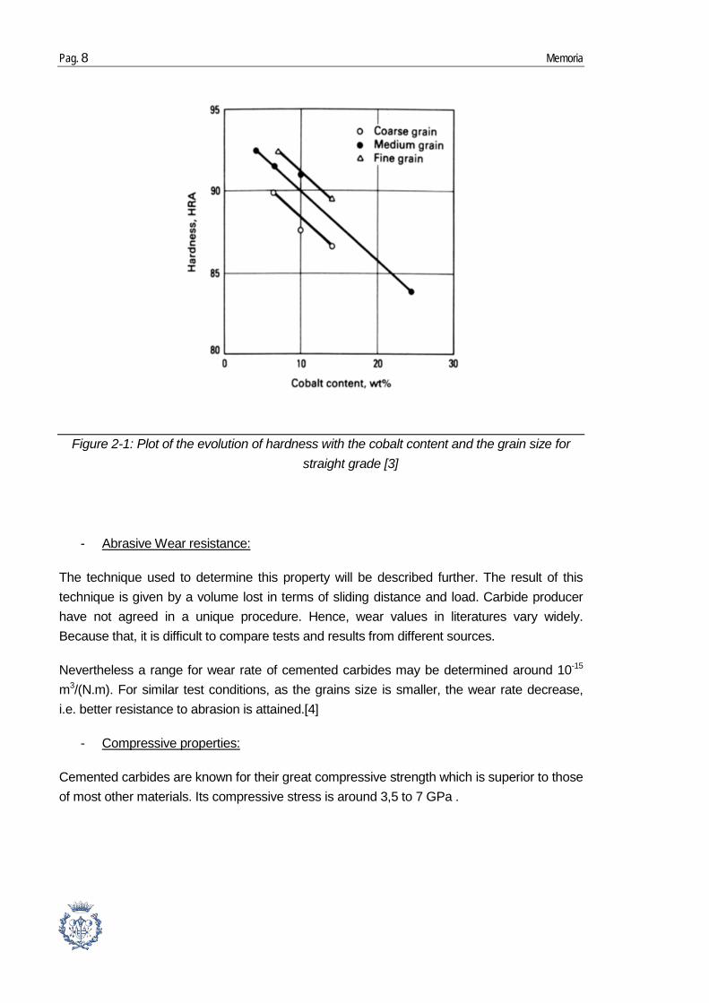
Hardness is commonly expressed as HRA (Rockwell A-scale). The value of hardness for cemented carbides is between 88 and 94 HRA [3]. On the Figure 2-1 it may be observed that a cemented carbide similar to the one here studied (10% cobalt and fine grain) get a hardness around 92HRA which amounts for about 1578 HV or 15.5GPa.
Moreover, it is known that for given cobalt content hardness increase with decreasing of WC grain size.[3]
Pag. 8 Memoria
-
The technique used to determine this property will be described further. The result of this technique is given by a volume lost in terms of sliding distance and load. Carbide producer have not agreed in a unique procedure. Hence, wear values in literatures vary widely. Because that, it is difficult to compare tests and results from different sources.
Abrasive Wear resistance:
Nevertheless a range for wear rate of cemented carbides may be determined around 10-15 m3/(N.m). For similar test conditions, as the grains size is smaller, the wear rate decrease, i.e. better resistance to abrasion is attained.[4]
-
Cemented carbides are known for their great compressive strength which is superior to those of most other materials. Its compressive stress is around 3,5 to 7 GPa .
Compressive properties:
Figure 2-1: Plot of the evolution of hardness with the cobalt content and the grain size for straight grade [3]

Contact damage under monotonic and cyclic loads of coated tool materials Pag. 9
A 73WC-22(Ti,Ta,Nb)C-5Co
B : 80WC-12(Ti,Ta,Nb)C-8Co
C : 86WC-8(Ti,Ta,Nb)C-6Co
D : 86WC-2(Ti,Ta,Nb)C-12Co
-
The toughness is measured in term of the critical stress intensity factor KIc. It is the capacity of a material to resist crack propagation.
Fracture toughness:
It may be observed that for cemented carbides fracture toughness increases with cobalt content and with tungsten carbide grain size. (Figure 2-3)
Figure 2-2: Plot of the Variation in compressive yield strength with temperature. Measure at 0.2% offset strain; all alloys characterized by medium grain size. [3]
Figure 2-3 : Plot of the variation in facture toughness (KIc) with cobalt content for WC-Co alloys with different tungsten carbide grain sizes.[3]
Pag. 10 Memoria
2.1.1.2. Tool Steel
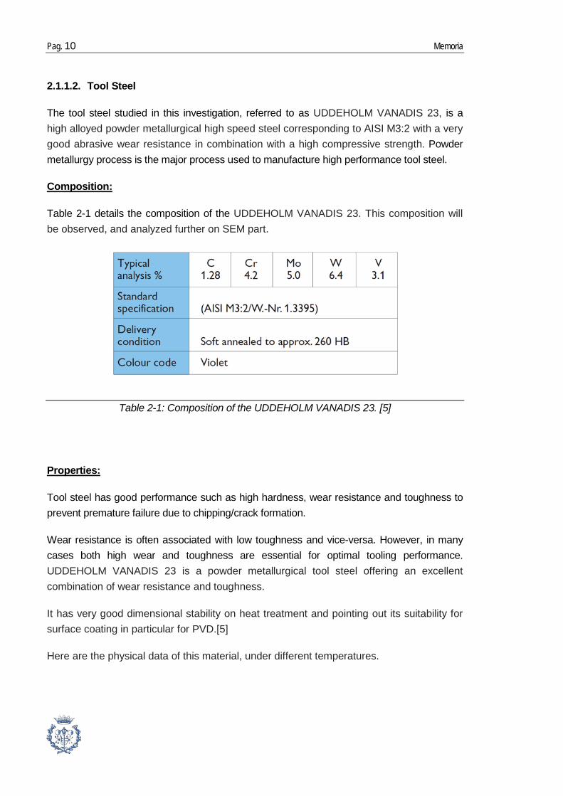
The tool steel studied in this investigation, referred to as UDDEHOLM VANADIS 23, is a high alloyed powder metallurgical high speed steel corresponding to AISI M3:2 with a very good abrasive wear resistance in combination with a high compressive strength. Powder metallurgy process is the major process used to manufacture high performance tool steel.
Table 2-1
Composition:
details the composition of the UDDEHOLM VANADIS 23. This composition will be observed, and analyzed further on SEM part.
Tool steel has good performance such as high hardness, wear resistance and toughness to prevent premature failure due to chipping/crack formation.
Properties:
Wear resistance is often associated with low toughness and vice-versa. However, in many cases both high wear and toughness are essential for optimal tooling performance. UDDEHOLM VANADIS 23 is a powder metallurgical tool steel offering an excellent combination of wear resistance and toughness.
It has very good dimensional stability on heat treatment and pointing out its suitability for surface coating in particular for PVD.[5]
Here are the physical data of this material, under different temperatures.
Table 2-1: Composition of the UDDEHOLM VANADIS 23. [5]

Contact damage under monotonic and cyclic loads of coated tool materials Pag. 11
2.1.2. Coatings
Hard coatings are often deposited onto tool materials for application in metal cutting. Coatings allow improving performances of the material. In general, performances depend on the combination of substrate and hard coating.[6]
2.1.2.1. Physical Vapor Deposition
PVD is an atomistic deposition method. The aim of this method is to fix a thin hard coating on a substrate. Material is vaporized from a liquid or solid source and move in forms of vapor composed by molecules and atoms in a vacuum or low pressure environment like plasma. This vapor condensed on the substrate and it deposits on it as film from 1nm to thousands of nanometer. The rate of this deposition is around one to hundred nanometers per second.
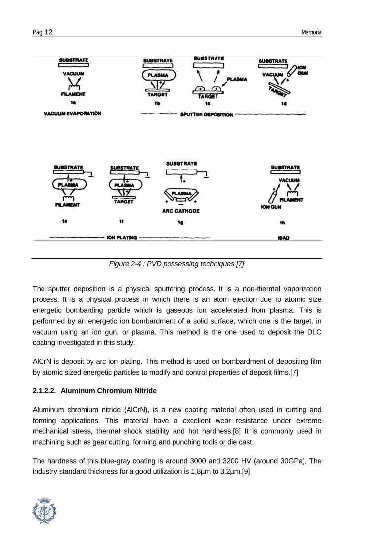
There are different types of PVD. The most known are the vacuum evaporation, the sputter deposition, and the ion plating. These methods are represented on Figure 2-4.
The vacuum evaporation technique consists on a thermal vapor deposition of a material on a substrate. It allows little or no collision with gas molecule, diminution of gaseous contamination and the thermal vaporization rate can be high compared to other vaporization.
Tableau 2-2: Physical data of UDDEHOLM VANADIS 23 under hardened and tempered conditions [5]
Pag. 12 Memoria
The sputter deposition is a physical sputtering process. It is a non-thermal vaporization process. It is a physical process in which there is an atom ejection due to atomic size energetic bombarding particle which is gaseous ion accelerated from plasma. This is performed by an energetic ion bombardment of a solid surface, which one is the target, in vacuum using an ion gun, or plasma. This method is the one used to deposit the DLC coating investigated in this study.
AlCrN is deposit by arc ion plating. This method is used on bombardment of depositing film by atomic sized energetic particles to modify and control properties of deposit films.[7]
2.1.2.2. Aluminum Chromium Nitride
Aluminum chromium nitride (AlCrN), is a new coating material often used in cutting and forming applications. This material have a excellent wear resistance under extreme mechanical stress, thermal shock stability and hot hardness.[8] It is commonly used in machining such as gear cutting, forming and punching tools or die cast.
The hardness of this blue-gray coating is around 3000 and 3200 HV (around 30GPa). The industry standard thickness for a good utilization is 1,8µm to 3,2µm.[9]
Figure 2-4 : PVD possessing techniques [7]

Contact damage under monotonic and cyclic loads of coated tool materials Pag. 13
2.1.2.3. Diamond like Carbon (DLC)
DLC (WC/C) is a generic term that is commonly used to describe a range of different types of amorphous carbon films.
DLC coatings are increasingly being used to improve the tribological performance of engineering components. These coatings posses advantageous mechanical properties such as high hardness, low friction coefficient and are generally chemically inert. Moreover, nitrogen, hydrogen, silicon or metal can be incorporated as dopant components. They allow controlling chemistry or tribochemistry of the films.
The coating used in this study is a hydrogenated DLC film (a-C:H) [10]. The inclusion of hydrogen is believed to pacify dangling bonds in the DLC structure, in turn reducing the defect coordination density and promoting the tetrahedral bonding of the carbon atoms.[11]
In addition to the excellent mechanical properties, DLC coatings can be smooth, pinhole and defect free and provide a good diffusion barrier to moisture and gases.
In recent years, the point of research was to apply DLC films on mass-produced mechanical components like in automotive sector. The aim of the film is to reduce frictional losses in higher stress contact. [11]
2.2. Characterization techniques
Characterization of the coated systems studied involved different techniques. It may be divided them into two categories. The first category concerns the techniques of structural characterization properties like SEM, confocal observation or calowear that allows characterizing the thickness of the coating. The second one concerns mechanical properties like scratch test and nano-indentation.
2.2.1. Structural characterization techniques
2.2.1.1. Scanning electron microscope (SEM)
The SEM is a microscope used to observe details with size inferior than 0.1 or 0.2 µm. It consists in bombarding the sample with electrons. The interaction between the sample and the electron creates secondary electrons. These electrons are detected by an Everhart-Thornley detector. The signal given by these electrons depends on the nature of the sample and the topography of the sample. In this way, by scanning, it may be obtain a map of the sample.

Pag. 14 Memoria
The SEM is composed of two major parts. The first one is the electronic console to adjust, focus and photography the image on a viewing screen. The second one and the more complicated is the electron column. It is in this second part where electron beam is created, focused and scanned across the sample. The column contains vacuum to allow electrons to travel. This column is composed of different parts.[12]
2.2.1.2. Calowear test - Thickness
The calowear is a quite cheap, easy and fast method to assess thickness and wear measurements.
Figure 2-5 : Schematic picture of a Scanning Electron Microscope[12]

Contact damage under monotonic and cyclic loads of coated tool materials Pag. 15
This technique provides quick, simple and inexpensive determinations of coating thickness. It is composed of a 50mm long and 50mm large working table, the shaft speed is from 60 to 1200 rpm, the standard ball diameters which can be used are 20, 25, 30mm.[13]
The functioning consists in making a ball, with a known diameter, drives by a rotor, rolls on the coated surface of the sample in order to fully wear out the coating and start to abrade the substrate. Slurry which contains SiC abrasives suspensions is continuously added on the contact point to improve the wear work. The ball rolls during few minutes. This experience leads to the emergence of a circular crater in both the coating and the substrate which can be observed with microscope.
If the substrate and the coating are abraded it may be observed two rings and calculate the thickness. If only one ring is discerned it is that the coating is not fully wear out and it requires abrading more.
By determining D1 and D2 the diameter of respectively the great and the small circle, we can determine X and Y. Next, using the equation:
(Eq. 3-1)
with D the diameter of the ball, the thickness of the coating (LT) may be measured.
Figure 2-6: Picture of a calowear

Pag. 16 Memoria
2.2.2. Mechanical characterization techniques
2.2.2.1. Calowear - wear resistance
The wear resistance is the ability of a metal to resist gradual wearing caused by abrasion and friction. To measure the wear resistance of a material the technique used is the same as the one used for thickness measurement.
The only difference to measure wear is that coating should not be fully worn out. By controlling the different factor of the test the wear coefficient of the coating may be calculated.
The abrasive wear of the sample is due to the sliding ball, of which the diameter is commonly 25mm, and the number of rotating cycles it does. This information makes the calculation of the ball slide distance possible. The normal force, which is detected by a loading cell beneath the sample, has also to be taken into account. The last important parameter is the volume of removing material, i.e. the volume of the crater (Eq. 3-2).
(Eq. 3-2)
with b the diameter of the spherical wear crater and D the diameter of the rotating ball.
Figure 2-7: schematic view of the crater formed by abrasion of the ball, with LT: the thickness of the coating

Contact damage under monotonic and cyclic loads of coated tool materials Pag. 17
By using all this parameters the wear coefficient (K) may be calculate (Eq. 3-3):
(Eq. 3-3)
With K the wear coefficient, S the sliding distance, and N the normal force applied by the ball.
2.2.2.2. Scratch test – Adhesion resistance
Scratch test is a method used in order to do qualitative measure of adhesion strength of thin hard coatings to its substrate.
The machine used is the REVETEST® Scratch Testing instrument. It is composed of a diamond stylus, acoustic emission detector, an optical microscope with video camera and it’s connected to a PC which controls the operation. It is used in order to characterized hard coating material with coating thickness of several microns.[14]
This test consists in doing a scratch on the coating with a Rockwell C diamond with a tip of 200µm (Figure 3-10). By increasing the load continuously or stepwise the coating, the aim is to find the critical load Lc. An acoustic signal is also recorded during the test and correlated to the contact failure mode.
Figure 2-8 : Picture of a scratch test machine.
Pag. 18 Memoria
Usually the critical load increases with substrate hardness and coating thickness, and decreases with increasing surface roughness. [16]
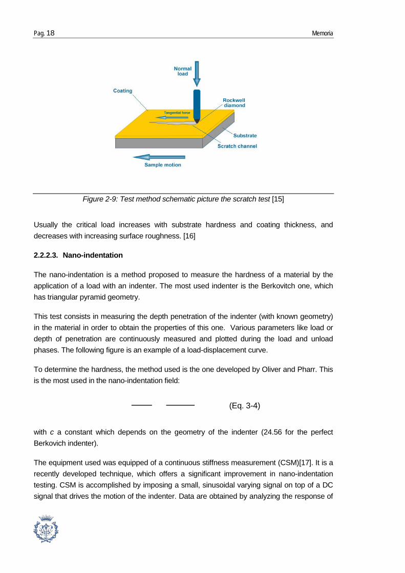
2.2.2.3. Nano-indentation
The nano-indentation is a method proposed to measure the hardness of a material by the application of a load with an indenter. The most used indenter is the Berkovitch one, which has triangular pyramid geometry.
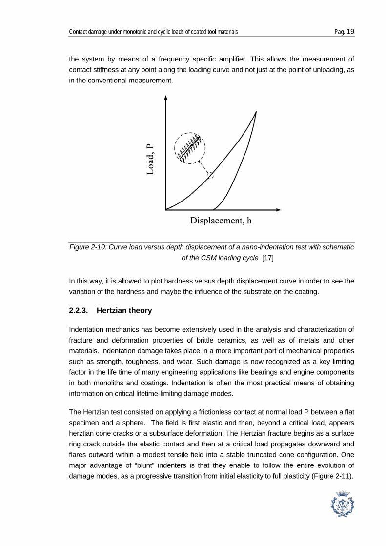
This test consists in measuring the depth penetration of the indenter (with known geometry) in the material in order to obtain the properties of this one. Various parameters like load or depth of penetration are continuously measured and plotted during the load and unload phases. The following figure is an example of a load-displacement curve.
To determine the hardness, the method used is the one developed by Oliver and Pharr. This is the most used in the nano-indentation field:
(Eq. 3-4)
with c a constant which depends on the geometry of the indenter (24.56 for the perfect Berkovich indenter).
The equipment used was equipped of a continuous stiffness measurement (CSM)[17]. It is a recently developed technique, which offers a significant improvement in nano-indentation testing. CSM is accomplished by imposing a small, sinusoidal varying signal on top of a DC signal that drives the motion of the indenter. Data are obtained by analyzing the response of
Figure 2-9: Test method schematic picture the scratch test [15]
Contact damage under monotonic and cyclic loads of coated tool materials Pag. 19
the system by means of a frequency specific amplifier. This allows the measurement of contact stiffness at any point along the loading curve and not just at the point of unloading, as in the conventional measurement.
In this way, it is allowed to plot hardness versus depth displacement curve in order to see the variation of the hardness and maybe the influence of the substrate on the coating.
2.2.3. Hertzian theory
Indentation mechanics has become extensively used in the analysis and characterization of fracture and deformation properties of brittle ceramics, as well as of metals and other materials. Indentation damage takes place in a more important part of mechanical properties such as strength, toughness, and wear. Such damage is now recognized as a key limiting factor in the life time of many engineering applications like bearings and engine components in both monoliths and coatings. Indentation is often the most practical means of obtaining information on critical lifetime-limiting damage modes.
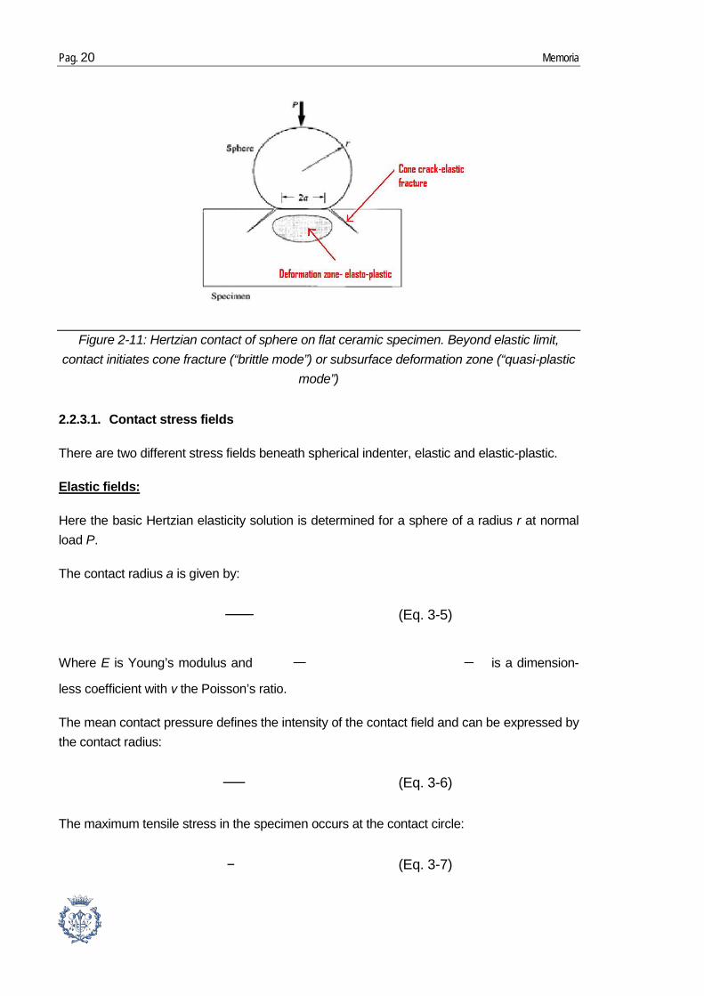
The Hertzian test consisted on applying a frictionless contact at normal load P between a flat specimen and a sphere. The field is first elastic and then, beyond a critical load, appears herztian cone cracks or a subsurface deformation. The Hertzian fracture begins as a surface ring crack outside the elastic contact and then at a critical load propagates downward and flares outward within a modest tensile field into a stable truncated cone configuration. One major advantage of “blunt” indenters is that they enable to follow the entire evolution of damage modes, as a progressive transition from initial elasticity to full plasticity (Figure 2-11).
Figure 2-10: Curve load versus depth displacement of a nano-indentation test with schematic of the CSM loading cycle [17]
Pag. 20 Memoria
2.2.3.1. Contact stress fields
There are two different stress fields beneath spherical indenter, elastic and elastic-plastic.
Here the basic Hertzian elasticity solution is determined for a sphere of a radius r at normal load P.
Elastic fields:
The contact radius a is given by:
(Eq. 3-5)
Where E is Young’s modulus and is a dimension-
less coefficient with ν the Poisson’s ratio.
The mean contact pressure defines the intensity of the contact field and can be expressed by the contact radius:
(Eq. 3-6)
The maximum tensile stress in the specimen occurs at the contact circle:
(Eq. 3-7)
Figure 2-11: Hertzian contact of sphere on flat ceramic specimen. Beyond elastic limit, contact initiates cone fracture (“brittle mode”) or subsurface deformation zone (“quasi-plastic
mode”)
Contact damage under monotonic and cyclic loads of coated tool materials Pag. 21
The maximum shear stress is located along the contact axis at a depth around 0,5a below the surface:
(Eq. 3-8)
By combining the expression of p0 the contact pressure (6) and a the contact radius (5), it leads to the expression of p0 in term of P the load and a :
(Eq. 3-9)
This previous equation describes a linear relation between p0 (indentation stress) and a/r. From this point, basic stress-stain information can be obtained.
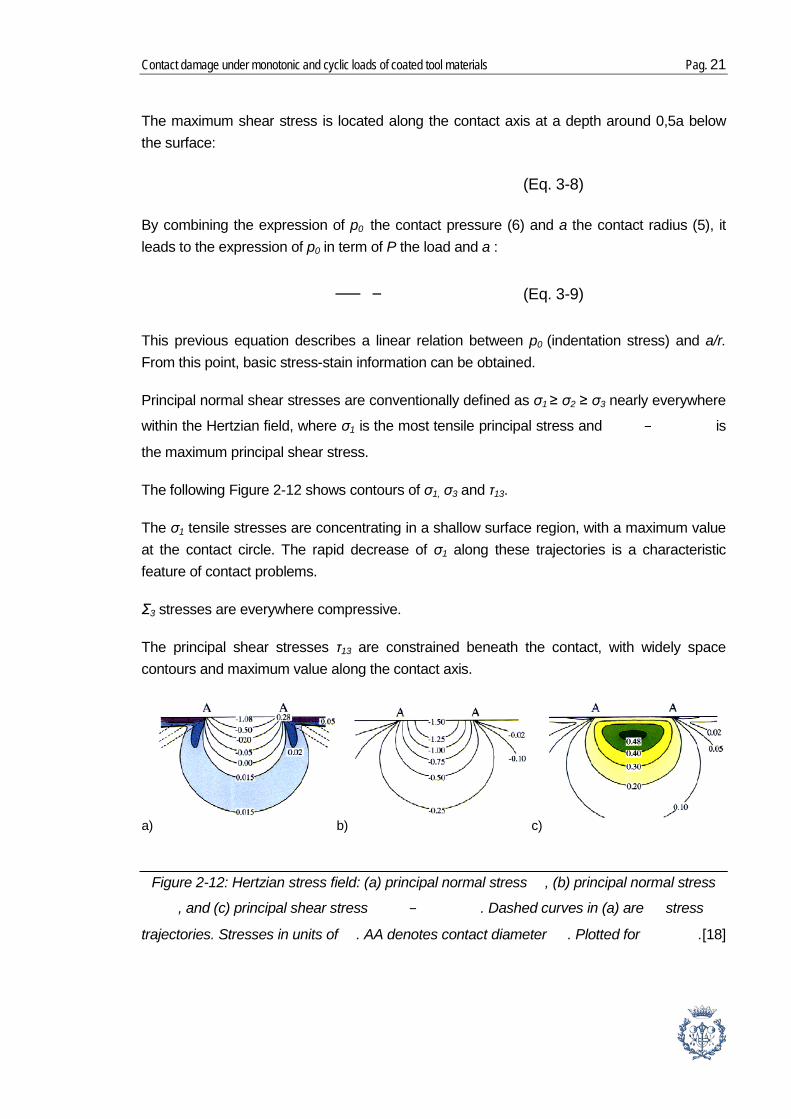
Principal normal shear stresses are conventionally defined as σ1 ≥ σ2 ≥ σ3 nearly everywhere
within the Hertzian field, where σ1 is the most tensile principal stress and is
the maximum principal shear stress.
The following Figure 2-12 shows contours of σ1, σ3 and τ13.
The σ1 tensile stresses are concentrating in a shallow surface region, with a maximum value at the contact circle. The rapid decrease of σ1 along these trajectories is a characteristic feature of contact problems.
Σ3 stresses are everywhere compressive.
The principal shear stresses τ13 are constrained beneath the contact, with widely space contours and maximum value along the contact axis.
a) b) c)
Figure 2-12: Hertzian stress field: (a) principal normal stress , (b) principal normal stress
, and (c) principal shear stress . Dashed curves in (a) are stress
trajectories. Stresses in units of . AA denotes contact diameter . Plotted for .[18]
Pag. 22 Memoria
Soft materials, such as metal, are subject of plastic flow beneath the contact above some yield point.
Elastic-plastic fields:
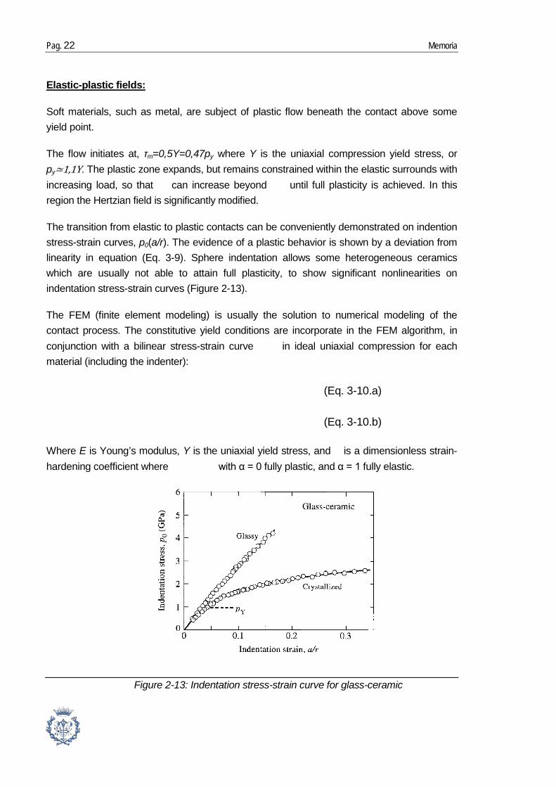
The flow initiates at, τm=0,5Y=0,47py where Y is the uniaxial compression yield stress, or py≃1,1Y. The plastic zone expands, but remains constrained within the elastic surrounds with increasing load, so that can increase beyond until full plasticity is achieved. In this region the Hertzian field is significantly modified.
The transition from elastic to plastic contacts can be conveniently demonstrated on indention stress-strain curves, p0(a/r). The evidence of a plastic behavior is shown by a deviation from linearity in equation (Eq. 3-9). Sphere indentation allows some heterogeneous ceramics which are usually not able to attain full plasticity, to show significant nonlinearities on indentation stress-strain curves (Figure 2-13).
The FEM (finite element modeling) is usually the solution to numerical modeling of the contact process. The constitutive yield conditions are incorporate in the FEM algorithm, in conjunction with a bilinear stress-strain curve in ideal uniaxial compression for each material (including the indenter):
(Eq. 3-10.a)
(Eq. 3-10.b)
Where E is Young’s modulus, Y is the uniaxial yield stress, and is a dimensionless strain-hardening coefficient where with α = 0 fully plastic, and α = 1 fully elastic.
Figure 2-13: Indentation stress-strain curve for glass-ceramic
Contact damage under monotonic and cyclic loads of coated tool materials Pag. 23
2.2.3.2. Contact damage modes
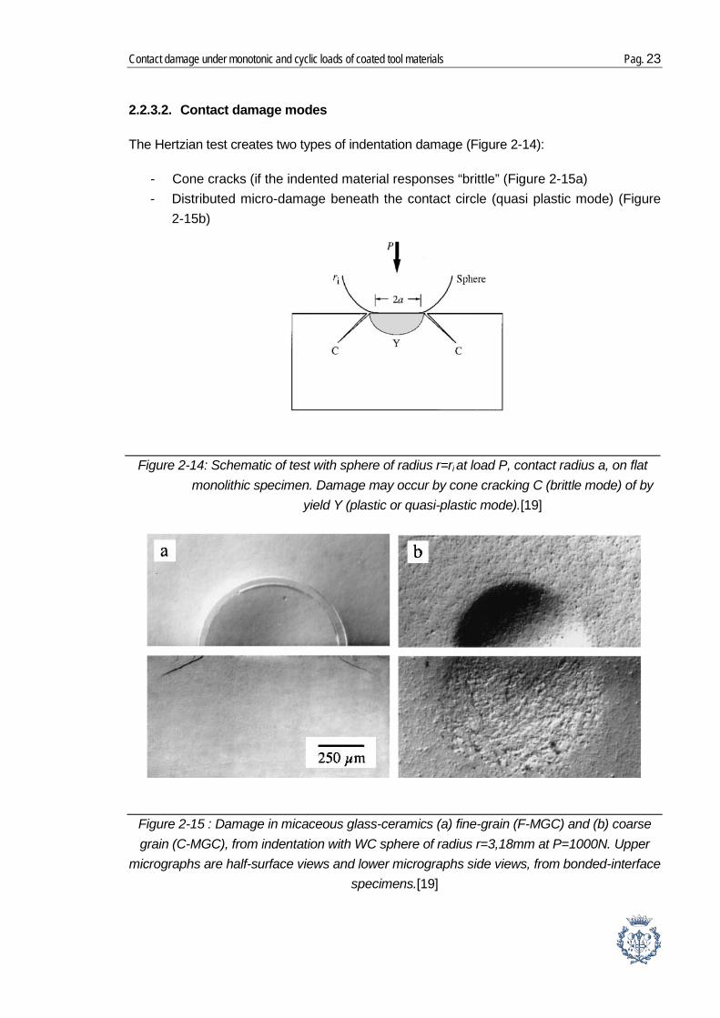
The Hertzian test creates two types of indentation damage (Figure 2-14):
- Cone cracks (if the indented material responses “brittle” (Figure 2-15a) - Distributed micro-damage beneath the contact circle (quasi plastic mode) (Figure
2-15b)
Figure 2-14: Schematic of test with sphere of radius r=ri at load P, contact radius a, on flat monolithic specimen. Damage may occur by cone cracking C (brittle mode) of by
yield Y (plastic or quasi-plastic mode).[19]
Figure 2-15 : Damage in micaceous glass-ceramics (a) fine-grain (F-MGC) and (b) coarse grain (C-MGC), from indentation with WC sphere of radius r=3,18mm at P=1000N. Upper
micrographs are half-surface views and lower micrographs side views, from bonded-interface specimens.[19]
Pag. 24 Memoria
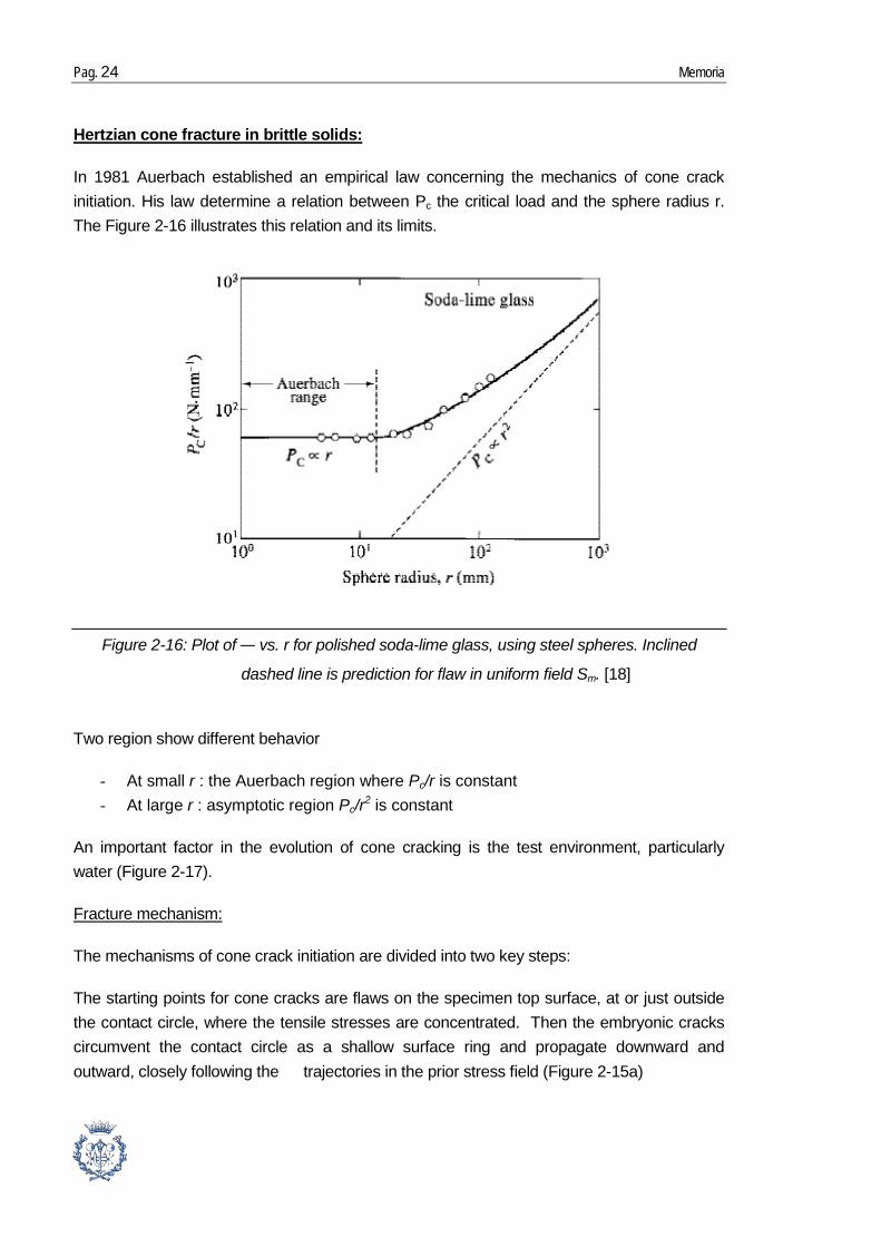
In 1981 Auerbach established an empirical law concerning the mechanics of cone crack initiation. His law determine a relation between Pc the critical load and the sphere radius r. The
Hertzian cone fracture in brittle solids:
Figure 2-16 illustrates this relation and its limits.
Two region show different behavior
- At small r : the Auerbach region where Pc/r is constant - At large r : asymptotic region Pc/r2 is constant
An important factor in the evolution of cone cracking is the test environment, particularly water (Figure 2-17).
The mechanisms of cone crack initiation are divided into two key steps:
Fracture mechanism:
The starting points for cone cracks are flaws on the specimen top surface, at or just outside the contact circle, where the tensile stresses are concentrated. Then the embryonic cracks circumvent the contact circle as a shallow surface ring and propagate downward and outward, closely following the trajectories in the prior stress field (Figure 2-15a)
Figure 2-16: Plot of vs. r for polished soda-lime glass, using steel spheres. Inclined
dashed line is prediction for flaw in uniform field Sm. [18]

Contact damage under monotonic and cyclic loads of coated tool materials Pag. 25
The most informative clues about the nature of the quasi-plastic mode can be found in the subsurface sections. One particularly useful technique involved presectionning a specimen into two half block and bond them together again and indenting across the surface trace of the bonded interface. Then by observation of the half surface and the section view damage we can obtain information.
Quasi-plasticity damage in tough ceramics
Figure 2-18 shows the half-surface and section views obtained in this way.
In this way, by observing the sequences of indentations at several loads, the entire evolution of the quasi plastic zone can be follow, from initial yield to full plasticity. Influence of the grain sizes on damage modes has been reported with the aid of the half-block technique.
2.2.3.3. Contact Fatigue
Repeated cycling can greatly exacerbate damage in ceramics, and compromise useful life. Contact fatigue testing provide a simple way of characterize the fatigue properties in order to plan their life cycle.
The Figure 2-19 compare the surface damage on moderately coarse alumina after n=1 and n=10 cycles at the same frequency in water. It’s clear that there is an evolution of damages with the number of cycle.
Figure 2-17: Critical load for cone initiation as function of time to fracture-abraded soda-lime glass, using steel spheres at constant crosshead speeds in different environments.[18]

Pag. 26 Memoria
Study the damage accumulation of two different micro-structural forms of silicon carbide: homogeneous-brittle and heterogeneous-tough were made. Figure 2-20
In the homogeneous, cycling creates light extension of cone cracks and at n=106 detaches surface from the cone mouth, while in the heterogeneous form the damage accumulation is much more accelerated. It starts by barely detectable quasi plastic zone at n=1 and ends with micro-crack coalescence and whole surface expulsion of material at n=106.
Figure 2-18: Hertzian indentation damage in machinable glass ceramic, from tungsten carbide sphere (r =1.98mm and P=1000N): (a) optical micrographs, half-surface and side view of indentation, bonded-interface specimen, surfaces gold coated after indentation, Nomarski interference; and (b) computed yield zone, contact
diameter AA, using FEM algorithm[18]
Figure 2-19: Indentation damage in coarse alumina (l=23µm) from tungsten carbide sphere (r=1.98mm and P=2000N) at 0.002Hz, in water: (a) n=1 and (b) n=10 cycles.
Surfaces gold coated after indentation, Nomarski interference.[18]

Contact damage under monotonic and cyclic loads of coated tool materials Pag. 27
Quasi-plastic ceramics are more susceptible to fatigue than their brittle counterparts. The difficulty of detection and the screening in its early stage make the quasi-plastic damage mode especially sneaky.
2.2.3.4. Layered structure
Laminate structures are often formed with brittle outlayers, like hard ceramics, to shield soft or compliant supporting underlayers or interlayers (metals, polymers, or even soft ceramics) from external forces. Brittle outlayers may also provide essential function, such as wear, corrosion, and thermal and electrical resistance. This notion of a protective outlayer is a critical aspect of cutting tools but also many engineering laminate structures, thermal barriers coatings (engine components), ceramic armor, laminated windows, eye glasses, and electronic packaging devices...
Figure 2-20: Section views of Hertzian contact sites in brittle (homogeneous) and tough (heterogeneous) silicon carbide from tungsten carbide sphere (r=3.18mm,
P=1000N, and f=10Hz), in air. Bonder-interface specimens, surfaces coated after indentation, Nomarski interference.[18]

Pag. 28 Memoria
A layered structure consist of ceramic plates of thickness d bonded to a substrate support. The same local Hertzian stress states responsible for cone cracking and quasi-plasticity persist at the near-contact regions in the ceramic top surface. However, the layered structure can induce new stress states in ceramic coating. The more the coatings become thinner the more the latter stresses become dominant. Coating flexure can modify the critical condition and generate subsurface radial cracks (R) within a bell-shaped distribution of tensile stresses at the coating undersurfaces. [19]
The geometry is similar to the cracks generated from quasi-plasticity zones in monoliths, where the stress field is different.
Consider a system of a brittle layer of thickness d on a thick compliant substrate, with a contact force P acting over a radius a at top surface. The contact area of spherical indenter ensures elastic deformation up to a critical load for fracture. Three regions of relative thickness d/a can be identify.[20]
- Thick coatings: The stresses are concentrated at the top surface and the fracture occurs close to the contact circle (max tensile stresses), as a near axisymmetric cone crack.
- Thin coatings: First the coating begins to flex and the primary maximum tensile stress appears to the coating lower surface. Then a radial crack initiates in the
Figure 2-20: Schematic of contact test with sphere on bilayer specimen with brittle coating, thickness d. Surface cone cracking C and yield Y are as in monoliths. Radial crack I initiates
at lower coating surface, in bell-shaped tensile region. Yield may also occur in soft substrate.[19]

Contact damage under monotonic and cyclic loads of coated tool materials Pag. 29
center region and propagate through the contact axis. And at the top surface, ring cracks form relatively shallow, outward from the contact circle.
- Thin films: Maximum tensile stresses are in the top surface, close to the contact circle. The effect of membrane stresses are increasing and overloading can lead to multiple cracking (punch in shear failure/delamination). Plasticity in coating or substrate reinforces the process.
Figure 2-21: Schematic of bilayer structure consisting of outer brittle layer of thickness d on thick compliant substrate, in axisymmetric contact on top surface at load P over a circular
area of radius a (not shown). Showing fracture mode transitions in brittle layer: (I) cone crack at top surface (thick coatings), (II) ring crack at top surface and radial crack at bottom surface
(thin coatings), and (III) concentric through-thickness ring cracks (thin films). [20]
Pag. 30 Memoria
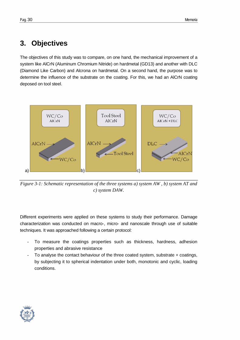
3. Objectives
The objectives of this study was to compare, on one hand, the mechanical improvement of a system like AlCrN (Aluminum Chromium Nitride) on hardmetal (GD13) and another with DLC (Diamond Like Carbon) and Alcrona on hardmetal. On a second hand, the purpose was to determine the influence of the substrate on the coating. For this, we had an AlCrN coating deposed on tool steel.
a) b) c)
Different experiments were applied on these systems to study their performance. Damage characterization was conducted on macro-, micro- and nanoscale through use of suitable techniques. It was approached following a certain protocol:
- To measure the coatings properties such as thickness, hardness, adhesion properties and abrasive resistance
- To analyse the contact behaviour of the three coated system, substrate + coatings, by subjecting it to spherical indentation under both, monotonic and cyclic, loading conditions.
Figure 3-1: Schematic representation of the three systems a) system AW , b) system AT and c) system DAW.

Contact damage under monotonic and cyclic loads of coated tool materials Pag. 31
4. Work Plan
This study has been developed between September 17th 2012, and February 15th 2013
Activities
September Report
Reading, collecting information,
getting familiar with equipment,
intro to testing procedures,
Thickness, scratch resistance,
nanoindentation H
Introduction
Objectives
Experimental procedure
17-sept 21-sept
24-sept 30-sept
October
01-oct 05-oct
08-oct * 12-oct * First report of preliminary results
15-oct 19-oct Static contact tests
and damage characterization
Introduction
Experimental procedure
Results November
29-oct 02-nov
05-nov * 09-nov * Second report of preliminary results
12-nov 16-nov
Wear resistance tests
Cyclic contact tests (Fatigue)
Results and
Discussion
Conclusions
19-nov 22-nov
25-nov 29-nov
December
03-déc 07-déc
10-déc 14-déc
17-déc *21-déc * Third report of final results
24-déc 28-déc
January
31-déc 04-janv
07-janv 11-janv
Finish final report writing and
15-janv
Preparation of thesis defence
18-janv
22-janv 25-janv
February
29-janv 01-febr
05-febr 08-febr
13-febr 15-febr
Final Presentation/thesis defense
Table 4-1: Work plan for PFC
Pag. 32 Memoria
5. Material and Methods
5.1. Nomenclature
In order to facilitate the writing of the report and the compression, the following nomenclature has been chosen:
Nomenclature: Substrate: Coating:
AW WC/Co AlCrN
DAW DLC and AlCrN
AT Tool Steel AlCrN
5.2. Structural characterization techniques
5.2.1. SEM sample preparation
The aim of this part was to observe and characterize the microstructure of the coated system. It requires a multistep preparation procedure.
The first step of the preparation was to cut them. This was done by using a diamond disc and cut a little piece of the end of the sample. The sample was positioned in order to have the smallest contact point between it and the disc. Then the obtained piece was cut into two parts and glued them together with coated faces facing each other in order to protect the coatings. Let the hard coating in contact with something less hard would have damaged it during the polishing.
The second step was to put the sample into Bakelite which is a thermosetting phenol formaldehyde resin. It helped to polish and manipulate the sample. The sample was put in a press, and added Bakelite, closed and warmed around 180°C to obtain a compact cylinder.
The last step was to polish the samples. To do this part a technique used in previous works was implemented [21]. This procedure was specially customized for coating-substrate system. The procedure was first to grind the sample from rough to softer disc in order to obtain a surface the flattest as possible. The second part was to pre-polish and
Table 5-1: Nomenclature
Contact damage under monotonic and cyclic loads of coated tool materials Pag. 33
polish using lubricant with little particles from 6µm to 1µm to obtain a mirror polished surface.
The following table resumes the different step of this polishing method:
Step Process Abrasive + lubricant
Disc
n° 1 Grinding Water MD-piano 220
n° 2 Soft grinding Water MD-piano 600
n° 3 Soft grinding Water MD-piano 1200
n° 4 Pre polish 6 diamond + lubricant
MD-Plan
n° 5 Pre polish 3 diamond + lubricant
MD-Nap
n° 6 Polish + water MD-Nap
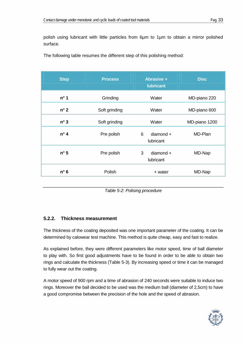
5.2.2. Thickness measurement
The thickness of the coating deposited was one important parameter of the coating. It can be determined by calowear test machine. This method is quite cheap, easy and fast to realize.
As explained before, they were different parameters like motor speed, time of ball diameter to play with. So first good adjustments have to be found in order to be able to obtain two rings and calculate the thickness (Table 5-3). By increasing speed or time it can be managed to fully wear out the coating.
A motor speed of 900 rpm and a time of abrasion of 240 seconds were suitable to induce two rings. Moreover the ball decided to be used was the medium ball (diameter of 2,5cm) to have a good compromise between the precision of the hole and the speed of abrasion.
Table 5-2: Polising procedure

Pag. 34 Memoria
Motor speed (rpm) Time (sec) Ball diameter (mm) Nb of ring
first test 600 180 25 1
second test 900 180 25 1
third test 900 240 25 2
After having created a crater, it was possible to observe it by using the microscope which is fixed on the machine. This microscope is directly connected to a computer containing software which allowed calculating the thickness.
This software allows calculating the thickness in an easy way. It is just needed to indicate the scale of the picture and to draw two different cycles around the crater. With these indications, the software calculated their diameters and by applying the equation quoting previously (Eq. 3-1), it showed the thickness.
Experiment was calculated for the three systems. It was done at least 5 times on a sample of each system, except for the AT samples. Indeed, samples were available for this system as it
Table 5-3 Detail of the first test to find good parameters
Figure 5-1: Example of a crater made on an AW system
Contact damage under monotonic and cyclic loads of coated tool materials Pag. 35
was coated on each side, so 3 tests were done on one side, and one on the opposite side to confirm, and this on 3 different samples.
5.3. Mechanical characterization technique
5.3.1. Scratch test
To determine the adhesion strength of coating a critical load has to be determined. It was defined as a given normal force which produces a specific and reproducible type of damage. The samples showed a high roughness value. The average surface roughness is determined by R-parameters which give information about the surface heights. Ra (arithmetic roughness average) is the most widely used. It is the arithmetic mean of the absolute values of the surface departures from the mean plane.
(Eq. 5-1)
M and N are the number of data points in X and Y directions and Z is the surface height relative to the reference mean plane.
In the samples studied, quite high roughnesses were measured according to those found in literature. [22]
Therefore, it was impossible to detect small amounts of coating damage on the specimen. In this way, we defined three different critical loads, as indicated as this following order [23]:
1) F N,CAE is given by the AE (Acoustic Emission) 2) F N,CI correspond to the first cohesive coating failure 3) F N,CII is measured at the first exposure of the underlying substrate. (It is not
necessarily by adhesive failure.)
Commonly on PVD coating tools, the critical loads is around 60N and 70N, and for scratch testing with Rockwell-C diamond tip the satisfactory critical load admitted in sliding contact indentation is 30N.[16]
For each system scratches were made in order to find these three critical loads. The idea was to make a test with a constant increasing load and be able to observe the three different critical loads in one test.
Different tests were initially conducted in the AW system, before finding the good range of parameters. Finally a 5mm long scratch track with a load from 0 to 100N was applied and a speed of 100N/min corresponding to 5mm/min. Then for the AT system similar testing parameters were used.
Pag. 36 Memoria
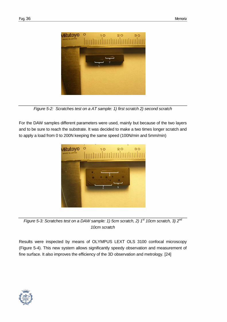
For the DAW samples different parameters were used, mainly but because of the two layers and to be sure to reach the substrate. It was decided to make a two times longer scratch and to apply a load from 0 to 200N keeping the same speed (100N/min and 5mm/min)
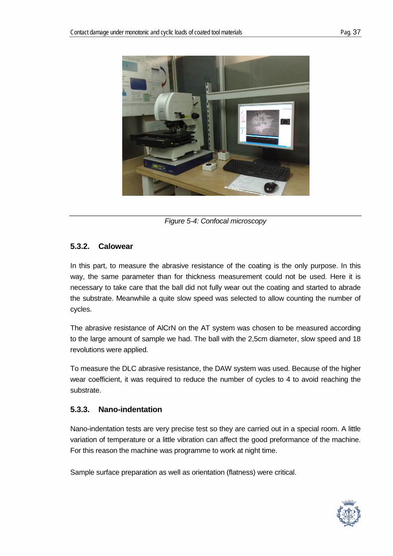
Results were inspected by means of OLYMPUS LEXT OLS 3100 confocal microscopy (Figure 5-4). This new system allows significantly speedy observation and measurement of fine surface. It also improves the efficiency of the 3D observation and metrology. [24]
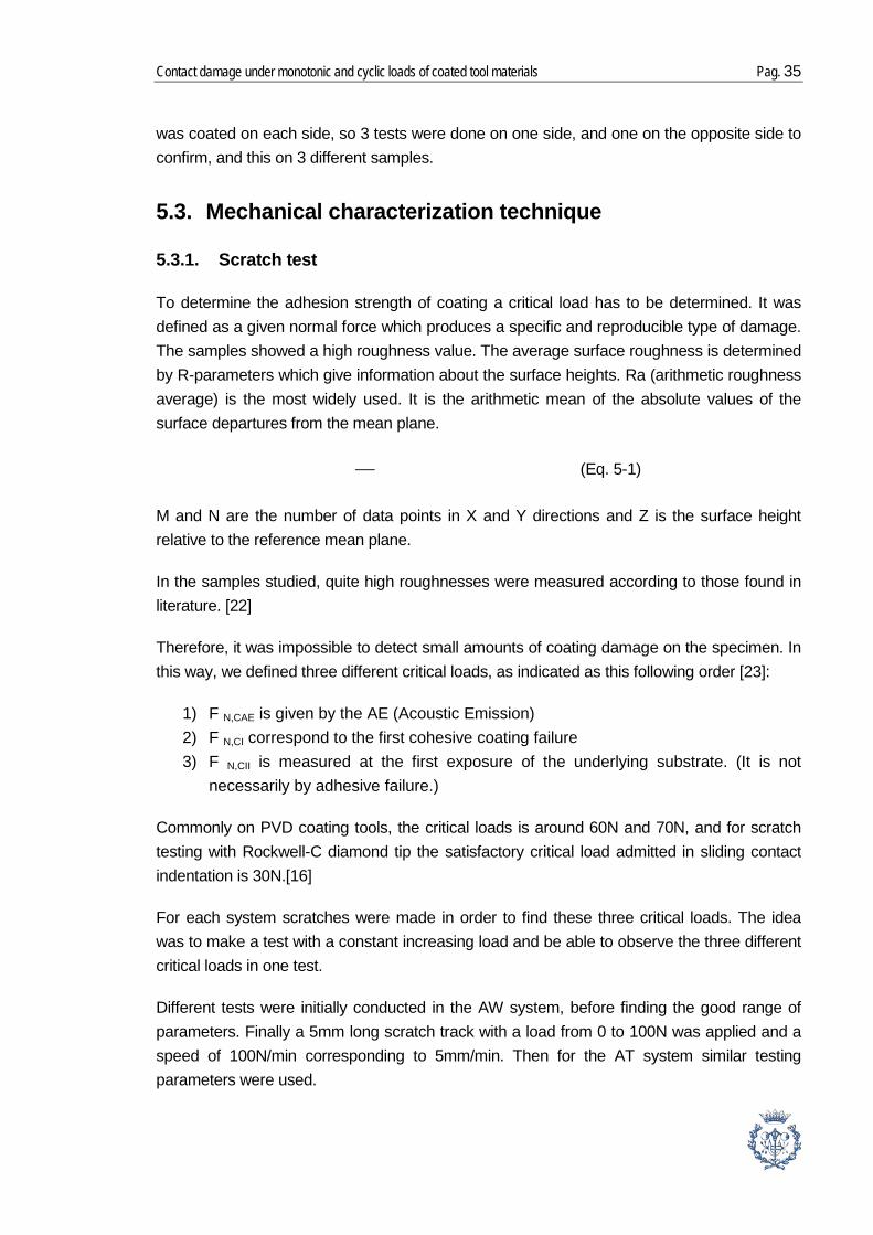
Figure 5-2: Scratches test on a AT sample: 1) first scratch 2) second scratch
Figure 5-3: Scratches test on a DAW sample: 1) 5cm scratch, 2) 1st 10cm scratch, 3) 2nd 10cm scratch
Contact damage under monotonic and cyclic loads of coated tool materials Pag. 37
5.3.2. Calowear
In this part, to measure the abrasive resistance of the coating is the only purpose. In this way, the same parameter than for thickness measurement could not be used. Here it is necessary to take care that the ball did not fully wear out the coating and started to abrade the substrate. Meanwhile a quite slow speed was selected to allow counting the number of cycles.
The abrasive resistance of AlCrN on the AT system was chosen to be measured according to the large amount of sample we had. The ball with the 2,5cm diameter, slow speed and 18 revolutions were applied.
To measure the DLC abrasive resistance, the DAW system was used. Because of the higher wear coefficient, it was required to reduce the number of cycles to 4 to avoid reaching the substrate.
5.3.3. Nano-indentation
Nano-indentation tests are very precise test so they are carried out in a special room. A little variation of temperature or a little vibration can affect the good preformance of the machine. For this reason the machine was programme to work at night time. Sample surface preparation as well as orientation (flatness) were critical.
Figure 5-4: Confocal microscopy
Pag. 38 Memoria
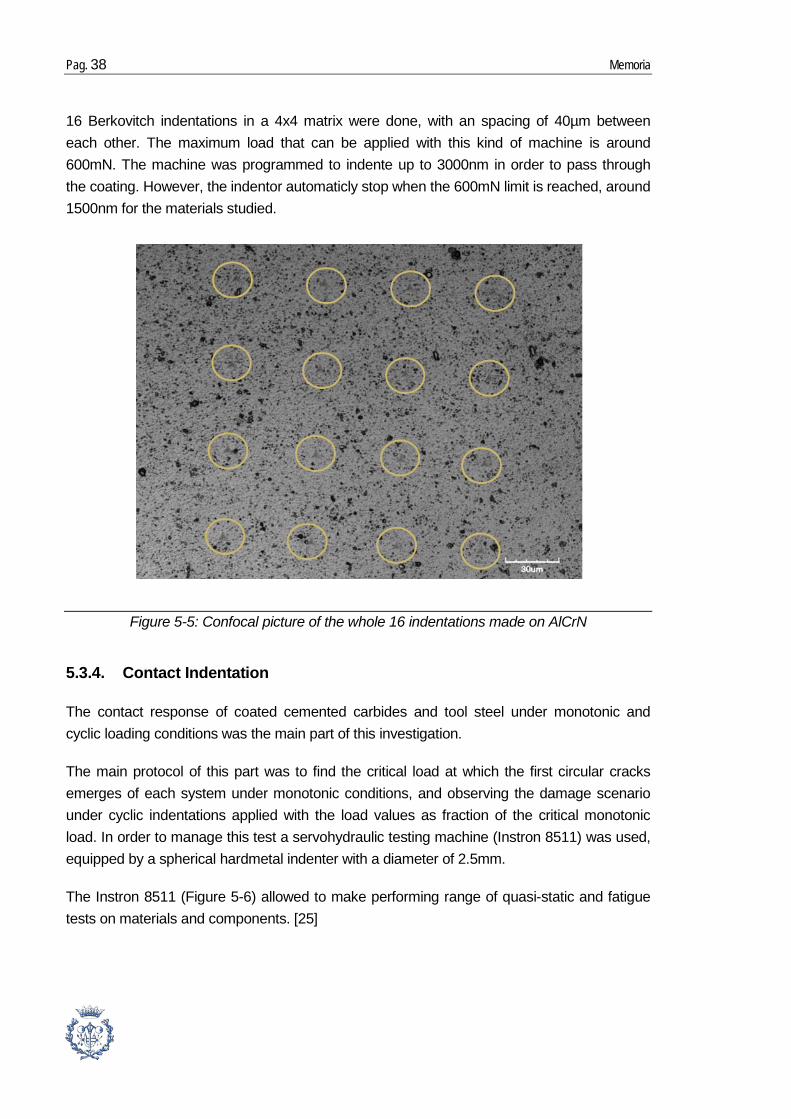
16 Berkovitch indentations in a 4x4 matrix were done, with an spacing of 40µm between each other. The maximum load that can be applied with this kind of machine is around 600mN. The machine was programmed to indente up to 3000nm in order to pass through the coating. However, the indentor automaticly stop when the 600mN limit is reached, around 1500nm for the materials studied.
5.3.4. Contact Indentation
The contact response of coated cemented carbides and tool steel under monotonic and cyclic loading conditions was the main part of this investigation.
The main protocol of this part was to find the critical load at which the first circular cracks emerges of each system under monotonic conditions, and observing the damage scenario under cyclic indentations applied with the load values as fraction of the critical monotonic load. In order to manage this test a servohydraulic testing machine (Instron 8511) was used, equipped by a spherical hardmetal indenter with a diameter of 2.5mm.
The Instron 8511 (Figure 5-6) allowed to make performing range of quasi-static and fatigue tests on materials and components. [25]
Figure 5-5: Confocal picture of the whole 16 indentations made on AlCrN

Contact damage under monotonic and cyclic loads of coated tool materials Pag. 39
We started this part by the monotonic indentation, to find the monotonic critical load.
5.3.4.1. Monotonic indentation
The monotonic test was applied under a monotonic load in a trapezoidal waveform (Figure 5-7). The first part was the application of the loading, with a speed of 30N/sec, then the load was hold constant at a determined value during 15sec, and finally, the unloading part in which the load decreased to zero.
0
100
200
300
400
500
600
700
0 10 20 30 40 50
Load
(N)
Time (s)
Figure 5-6: Picture of an Instron 8511
Figure 5-7: Example of trapezoidal waveform

Pag. 40 Memoria
For each sample the protocol was to indent progressively by increasing 100N each step (Figure 5-8). The first load was chosen to be 600N.
At the end of each test, a depression (Figure 5-9) was formed on the sample. The aim was to observe it with a confocal microscope with x50 or x100 objective, in order to determine if there had been formation of circular cracks, cohesive failures or other damages.
After the observation of the indentation and the determination of a critical load, a second range of indentation loads were assessed around the critical load to confirm that the result and the measures were reproducible.
Figure 5-8: Picture of a AT sample with 12 indentations from 1) 600N to 12) 1700N
Figure 5-9: Picture of an indentation of AlCrN coating on WC/Co substrate
320µm
Contact damage under monotonic and cyclic loads of coated tool materials Pag. 41
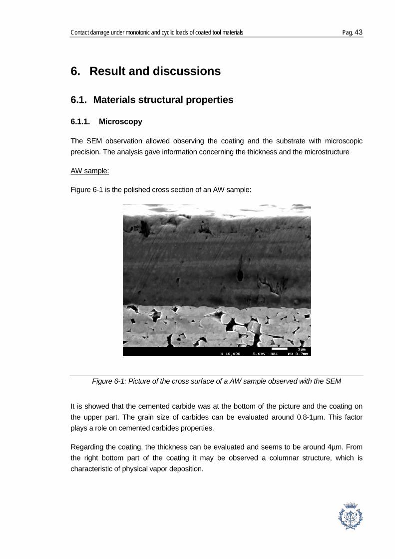
5.3.4.2. Fatigue indentation
The fatigue indentation is induced by a cyclic waveform (Figure 5-11) with a 10Hz frequency, and a ratio of 0.1. In this study the number of cycle was 100000, so one test was approximately 3 hours long.
According to the result of monotonic indentation, following this protocol was decided for the cyclic indentation (Table 5-5).
0
200
400
600
800
1000
1200
0 0,2 0,4 0,6 0,8 1
Load
(N)
Time (s)
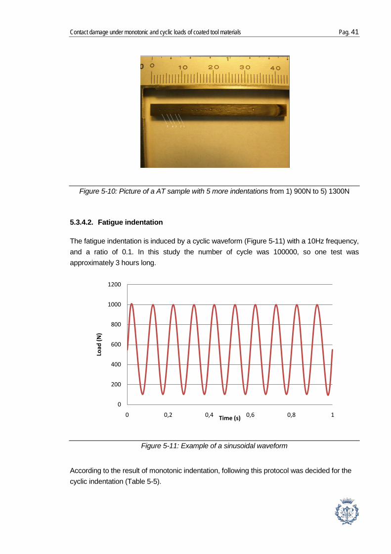
Figure 5-10: Picture of a AT sample with 5 more indentations from 1) 900N to 5) 1300N
Figure 5-11: Example of a sinusoidal waveform

Pag. 42 Memoria
1000N 1500N 2000N DAW
AW
AT
As it was the case for monotonic indentation, the tests have to be performed twice in order to confirm the reproducibility of the measurements.
Table 5-4: Protocol of the cyclic indentation
Contact damage under monotonic and cyclic loads of coated tool materials Pag. 43
6. Result and discussions
6.1. Materials structural properties
6.1.1. Microscopy
The SEM observation allowed observing the coating and the substrate with microscopic precision. The analysis gave information concerning the thickness and the microstructure
Figure 6-1
AW sample:
is the polished cross section of an AW sample:
It is showed that the cemented carbide was at the bottom of the picture and the coating on the upper part. The grain size of carbides can be evaluated around 0.8-1µm. This factor plays a role on cemented carbides properties.
Regarding the coating, the thickness can be evaluated and seems to be around 4µm. From the right bottom part of the coating it may be observed a columnar structure, which is characteristic of physical vapor deposition.
Figure 6-1: Picture of the cross surface of a AW sample observed with the SEM

Pag. 44 Memoria
Figure 6-2 is a defect on a coating, due to a mechanical break. On this picture it is easier to confirm the columnar structure created by PVD.
The bilayer was also observed with SEM:
DAW Sample:
Figure 6-2: Picture of a defect on the coating of the AW sample observed with the SEM
Figure 6-3: Picture of the cross section of a DAW sample observed with the SEM
Contact damage under monotonic and cyclic loads of coated tool materials Pag. 45
From this picture it can be observed the three different parts: at the bottom there is the substrare, the cemented carbides with the WC grain, as before the size seems to be around 1µm or lower.
In the middle it may be seen the AlCrN coating which is around 2,5µm thick and exhibits a columnar structure.
The upper part is the top coating DLC. It is somehow damaged because this part was in contact with bakelite which is really less hard. In spite of this damage, the thickness can be evaluated around 3µm.
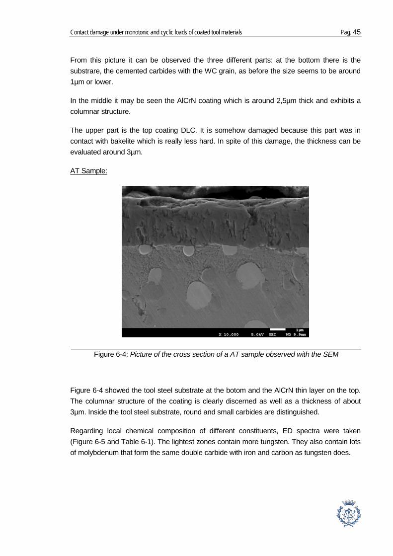
AT Sample:
Figure 6-4 showed the tool steel substrate at the botom and the AlCrN thin layer on the top. The columnar structure of the coating is clearly discerned as well as a thickness of about 3µm. Inside the tool steel substrate, round and small carbides are distinguished.
Regarding local chemical composition of different constituents, ED spectra were taken (Figure 6-5 and Table 6-1). The lightest zones contain more tungsten. They also contain lots of molybdenum that form the same double carbide with iron and carbon as tungsten does.
Figure 6-4: Picture of the cross section of a AT sample observed with the SEM

Pag. 46 Memoria
The darkest points contain more iron. The less dark points contain vanadium which promote the formation of very hard and stable carbides, thus increase the efficiency of tools. The spectrum 5 shows traces of silicon. Silicon gives a slight increase in maximum attainable tempered hardness and has some influence on carbide morphology, although there seems
Figure 6-5: SEM observation of the tool steel of the AT sample
Processing option : All elements analysed (Normalised)
Spectrum In stats. C O Si V Cr Fe Mo W Total
Spectrum 2 Yes 12.29 2.53 3.39 27.53 21.32 32.94 100.00
Spectrum 3 Yes 10.52 4.32 3.86 70.00 5.61 5.69 100.00
Spectrum 4 Yes 17.44 3.40 19.77 4.03 35.45 9.50 10.41 100.00
Spectrum 5 Yes 7.33 0.62 0.76 4.62 84.56 2.11 100.00
Max. 17.44 3.40 0.62 19.77 4.62 84.56 21.96 33.41
Min. 7.33 3.40 0.62 0.76 3.39 27.53 5.61 2.11
Table 6-1: Analysed of the spectrum indicated on Figure 6-5.(in %weight)
Contact damage under monotonic and cyclic loads of coated tool materials Pag. 47
to be a slight decrease in toughness. Traces of cobalt are detected. Cobalt increases the hot hardness and thus the cutting efficiency when high temperatures are attained, and also chromium which increase oxidation-resistance.
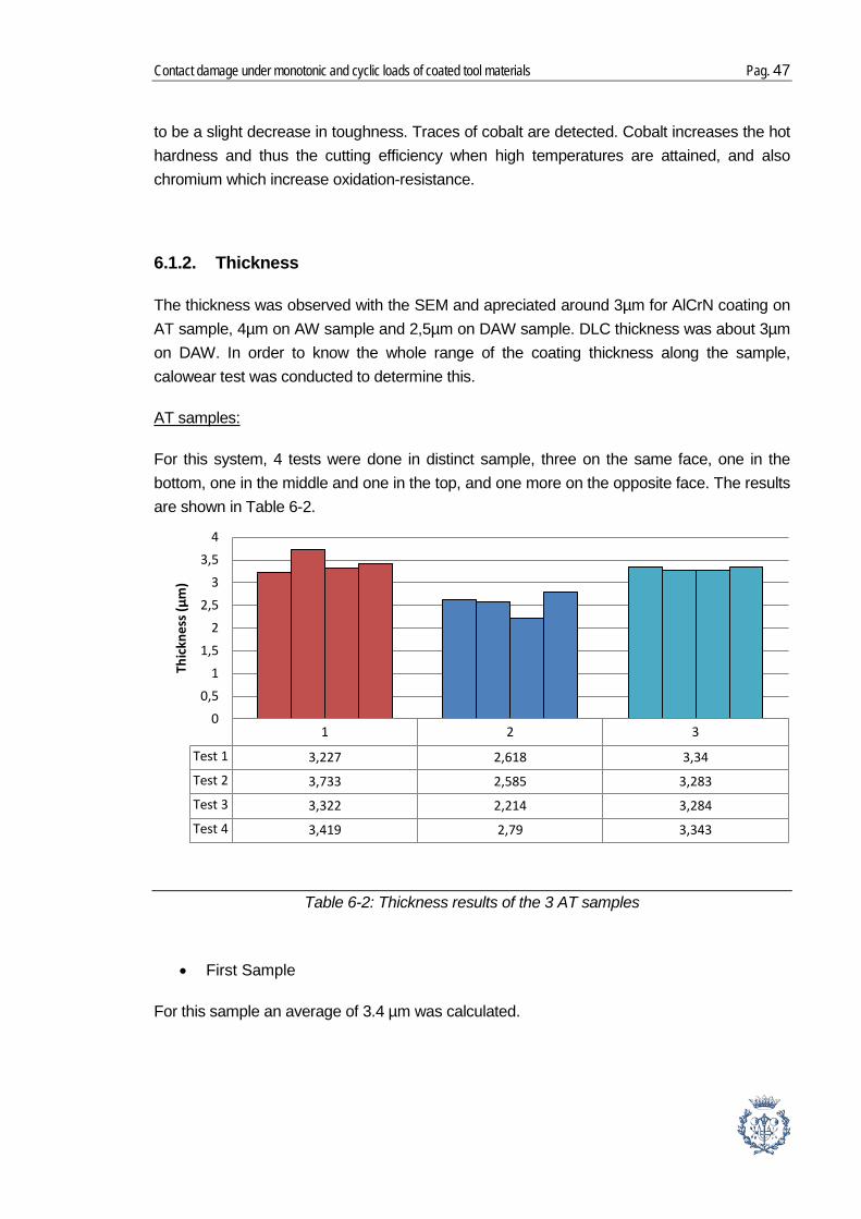
6.1.2. Thickness
The thickness was observed with the SEM and apreciated around 3µm for AlCrN coating on AT sample, 4µm on AW sample and 2,5µm on DAW sample. DLC thickness was about 3µm on DAW. In order to know the whole range of the coating thickness along the sample, calowear test was conducted to determine this.
For this system, 4 tests were done in distinct sample, three on the same face, one in the bottom, one in the middle and one in the top, and one more on the opposite face. The results are shown in
AT samples:
Table 6-2.
• First Sample
For this sample an average of 3.4 µm was calculated.
1 2 3
Test 1 3,227 2,618 3,34
Test 2 3,733 2,585 3,283
Test 3 3,322 2,214 3,284
Test 4 3,419 2,79 3,343
00,5
11,5
22,5
33,5
4
Thic
knes
s (µm
)
Table 6-2: Thickness results of the 3 AT samples
Pag. 48 Memoria
• Second sample
The average on the second sample is 2,5 µm. Thus it may be observed that the two samples studied are not equals. The average thickness of this one is almost 1 µm less than the first one. However standard deviation in both cases is 0,2.
• Third Sample
This third sample is also constant with a standard deviation of 0,1. The thickness of this one is smaller than for the first one, 3.3 µm.
• Average thickness
Sample 1 Sample 2 Sample 3 All Sample
LT av (µm) 3,4 2,5 3,3 3,1
Standard deviation 0,2 0,2 0,1
It may be concluded from these tests that there were some variations from one sample to another. Thus an average of the results may be taken and conclude that the thickness was 3.1µm (+/- 0,5µm). The other factor was that the coating seemed to be constant on each sample, as the standard deviation of the results was quite small.
In this second system, only 4 samples were available.Hence, the idea was to do several tests in one unique sample.
AW sample :
Results are shown in Table 6-4:
Table 6-3: Average and standard deviation of TA sample thickness.

Contact damage under monotonic and cyclic loads of coated tool materials Pag. 49
In this sample it may be observed that the coating was not constant along the sample. However by considering the position where the tests were made it can be observed that the thickness was higher in the middle than closer to edges.
1st test 2nd test 3rd test 4th test 5th test 6th test
AlCrN (µm) 2,103 3,522 2,113 3,06 2,881 2,886
0
0,5
1
1,5
2
2,5
3
3,5
4
LT (µ
m)
Table 6-4: Histogram of the thickness results of AW sample
Figure 6-6: Map of the AW with the different calowear tests. From left to right: 3) 2.113µm, 6) 2.886µm, 4) 3.06µm, 2) 3.522µm, 5) 2.881µm, 1) 2.103µm.

Pag. 50 Memoria
By measuring the location of each crater on the sample and their corresponding thickness it could be traced a curve representing the thickness along the surface. From this curve it is clearly seen that the profile of the thickness was convex, thin at the edge and thicker in the middle.
This system was a bilayer one, therefore two different thicknesses were mesured. Like the previous system, only a few samples were available; thus tests were conducted in one sample.
DAW sample:
00,5
11,5
22,5
33,5
4
0 5 10 15 20 25
Thic
knes
s of t
he c
oatin
g (µ
m)
Position along the sample (µm)
1st test 2nd test 3rd test 4th test 5th test 6th test 7th test
DLC 3,8 3,366 3,112 3,55 3,233 3,454 3,414
AlCrN 2,655 1,703 2,229 1,922 2,296 2,366 2,21
01234567
LT (µ
m)
Figure 6-7: Curve representing the thickness of the AW coating according to the position on the sample
Figure 6-8: Thickness results of DAW sample: AlCrN in blue and DLC in red

Contact damage under monotonic and cyclic loads of coated tool materials Pag. 51
The average of AlCrN thickness was 2.2 µm and it was constant along the sample. The standard deviation was 0,3. For DLC coating it was higher, 3,4µm and it was constant too, the standard deviation is 0,2. This confirms the approximation which was found from the SEM observation.
6.2. Mechanical properties
6.2.1. Adhesion properties
The scratch test leads to assessment of adhesion properties. The details are given below:
The experiments conducted on the first system (AW) leaded to the curves shown in
AW sample
Figure 6-9. The blue curve is the one which is the most interesting as it is the plot of the acoustic emission. According to this curve FN,CAE may be determined. The first acoustic emissions appeared in 30N and they intensified at 95N.
The first acoustic emission was at 30N and it corresponds to 1.5mm. At this place (Figure 6-10) it could be observed the apparition of the first cracks.
Figure 6-9: Plot of the scratch test results of AW

Pag. 52 Memoria
The second acoustic emission at the end of the cracks appears at 4,75mm at a load of 95N (Figure 6-11), it seems to be the F N,CI but also the F N,CII because there, it was discerned the first cohesive failure but also the apparition of the substrate.
Figure 6-12
AT sample:
shows the results, once again, the plot of the acoustic emissions for AT sample is shown in blue. It may be seen that the first acoustic emissions correspond to a critical load of 30N.
Figure 6-10: Pictures of the first cracks corresponding to FN,CAE which appears at a critical load of 30N
Figure 6-11: Pictures of the track at a load of 95N, first apparition of the substrate

Contact damage under monotonic and cyclic loads of coated tool materials Pag. 53
The microscopic observations, with the confocal, leaded to the following images. Around 1,55mm the first cracks may be discerned, which correspond to FN,CAE=30N and just after the first cohesive failures(F N,CI). Thus F N,CI corresponded to a load around 35N. Next near 2,26mm, the substrate is started to show up. This correspond to F N,CII and could be measured at a load around 45N.
For this system there were two layers, thus, there is one critical load concerning DLC and another critical load concerning AlCrN. For acoustic emission, according to the following figure, the acoustic emissions started at 45N around 2mm and corresponded to DLC coating.
DAW samples:
Figure 6-12: Plot of the scratch test results of AT with a first acoustic emission at 30N
Figure 6-13: Pictures of the whole scratch on an AT with the critical zones

Pag. 54 Memoria
Figure 6-15 shows that around 2mm, the first cohesive failures on DLC may be seen. Thus the FN,CI corresponded to 45N approximately.
Then at 4.26mm the second coating starts to show up, (Figure 6-16), at that point DLC was completely removed. This phenomenon could be ascribe to the FN,CII of the first coating, and it corresponded to a load of 85N. Then around 5.39mm there was evidence of the substrate so here it was F N,CII of the second coating and it corresponded to 105N.
Figure 6-14: Plot of the scratch test results of DAW with a first acoustic emission at 45N
Figure 6-15: Pictures of the scratch beginning on a DAW sample first cohesive failures

Contact damage under monotonic and cyclic loads of coated tool materials Pag. 55
On Table 6-5 the results are summarized:
FN,CAE (N)
Acoustic Emission
F N,CI (N)
First cohesive failure
F N,CII (N)
Exposure of the substrate
AT 30 35 45
AW 30 95 95
DAW 45 45 85 (DLC) 105(AlCrN)
Actually one unique definition of FN,C can be used, and depend on the application. Indeed in some operation like cold work forming even a small coating fragment detached by cohesive failure can be considered as critical, as it can decrease wear resistance or cause deterioration of the surface finish of the product, thus FN,C was determined as FN,CI.
For other application, like machining, those small fragments are less important since they are removed. In these cases, complete removal of small or large part of the tool (FN,CII) is considered as the critical load.[23]
Nevertheless, correlation between scratch test data and performance of the coated part remains poor. The contact condition of scratch test is not one hundred percent comparable with real service condition. However it gives an idea, and in this case FN,C was superior than 30N which was considered as the critical load in sliding contact indentation.[16]
Figure 6-16: Pictures of the whole scratch on a DAW sample with the critical zones
Table 6-5: Resume of the results obtained for scratch test
Pag. 56 Memoria
6.2.2. Abrasion properties
The abrasion tests were made only on two samples because the aim was to compare AlCrN and DLC coatings.
The results of AlCrN are given in Table 6-6. They were made using a 25 mm diameter ball of which the perimeter is 78,5mm.
The results are all around 3,6.10-14 m3/N.m. and seems to be quite reproducible.
For the DLC coating (Table 6-7) the results were lower, around, 2.10-13 m3/Nm except for one value which was more than twice higher.
As it may be seen from Table 6-6 and Table 6-7, AlCrN had a much smaller abrasion rate than DLC. The previous research showed that cover the surface with DLC provides a surface with low friction and low wear rate. Lots applications of DLC typically utilize the ability of the material to reduce abrasive wear and therefore reduce friction.[26]
Nevertheless, this technique comport some approximation. For example abrasive particles attached inside the wear scars can modify the behavior of the surface of the material during the test, which can lead to an artificial decrease in wear coefficient. Thus, the values of k given can be underestimated. However, the k values given for small sliding distances, L < 1 m, are strongly influenced by specific features related to the initial stages of the test, before the steady state is reached. Indeed there is scuffing in the edge region, which can lead to the overestimation of the craters diameter at low sliding distances. Moreover, at the
AlCrN (on TS) Exp 1 Exp 2 Exp 3
Cycles 18 18,75 18,25
S (mm) 1413,7 1472,6 1433,4
V (mm3) 3,7.10-5 4,3.10-5 4,1.10-5
N (N) 0,78 0,78 0,78
K (mm3/N mm) 3,3.10-8 3,8.10-8 3,6.10-8
K (m3/N m) 3,3.10-14 3,8.10-14 3,6.10-14
Table 6-6: Results of calowear tests for a AlCrN coating with S: the sliding distance, V: the crater volume, N: the normal force, K: the wear coefficient.
Contact damage under monotonic and cyclic loads of coated tool materials Pag. 57
initial stages of the test other factor can affect the wear coefficient like the surface roughness, the wettability of the abrasive suspension on the ball and the sample and the cold working induced by the metallographic sample preparation procedure, and others.[27]
For these reasons the previous results obtained by low number of cycle are to be considered with precaution. Moreover, as we commented before, producers did not agree on a unique technique for this test, so it was not possible to compare tests and results from different sources.
6.2.3. Hardness
The variation in nano-indentation hardness with indentation depth for each system is shown on this section. The indentations illustrated a depth limit from 1200 to 1400nm when the coatings have a thickness around 3000nm. This point is due to the fact that the coatings have a significant hardness and that the indentation machine can not apply loads superior to 600mN on the sample.
The experiment gave 16 results on 16 different points on the coating. With these results an average was done to plot one curve of the hardness versus the depth.
AW sample:
Figure 6-17 is the one plot with the AW results. The important standard deviation in the initial depth could be
DLC (on Wc/Co) Exp 1 Exp2 Exp 3 Exp 4
Cycles 4 3,5 3 3,3
S (mm) 314,2 274,9 235,6 259,2
V (mm3) 12,4.10-5 4,5.10-5 3,6.10-5 5,1.10-5
N (N) 0,85 0,85 0,85 0,85
K (mm3/N mm) 4,7.10-7 1,9.10-7 1,8.10-7 2,3.10-7
K (m3/N m) 4,7.10-13 1,9.10-13 1,8.10-13 2,3.10-13
Table 6-7: Results of calowear tests for a DLC coating with S: the sliding distance, V: the crater volume, N: the normal force, K: the wear coefficient

Pag. 58 Memoria
explained by the important roughness of the surface, so some indentation could be applied in holes while others were made on peaks, which lead to erroneous results.
This graphic showed hardness of the sample with the depth of indentation. As explained before, from 0 to 200 nm approximately the indenter was near the surface and because of the important roughness of the material all the 16 indentations could not give the same information. That created a large standard deviation. After this, a plateau around 35GPa is noticed which seemed to be the hardness of AlCrN. As the indentation did not go deeper than 1200nm, it was not really possible to determine the influence of the substrate. Indeed, by indenting deeper would have yield to hardness values falling close to the hardness of the substrate (substrate response).
In this system, AlCrN was deposited on tool steel. Indenting 16 times yield curve given in
AT sample:
Figure 6-18. As the previous one it may be observed a more important deviation on the initial depth indentations.
It could be observed that after 200nm there is a plateau between 30 and 35Gpa, which corresponded to the hardness of AlCrN, and confirmed the previous results. Moreover, here the substrate response may be inferred. Indeed around 500nm the substrate influence was visible, the hardness start to decrease with the depth increasing. This phenomenon was due to the fact that tool steel was softer than AlCrN. Hard coating on softer substrate lost their
20
25
30
35
40
45
50
0 200 400 600 800 1000 1200
Hard
ness
(GPa
)
Depth (nm)
Figure 6-17: Graphic of the hardness of AW versus the depth
Contact damage under monotonic and cyclic loads of coated tool materials Pag. 59
hard characteristic. This is an example of the influence that substrate has on coatings. As a result of this, it could be observed that the indenter was able to go deeper on the coating.
This sample was composed of two coatings, DLC and AlCrN, and according to the thickness of each coating it was not possible to observe any influence of the substrate. However it could be observed that the second layer AlCrN influences on the top layer DLC.
DAW sample:
Figure 6-19 shows the results of hardness test on DAW sample.
0
5
10
15
20
25
30
35
40
45
50
0 200 400 600 800 1000 1200 1400 1600 1800 2000
Hard
ness
(GPa
)
Depth (nm)
0
2
4
6
8
10
12
14
16
18
20
0 200 400 600 800 1000 1200 1400
Hard
ness
(Gpa
)
Depth (nm)
Figure 6-18: Graphic of the hardness of AT with the depth
Figure 6-19: Graphic of the hardness of DAW with the depth

Pag. 60 Memoria
As for the two other systems it may be seen that the low depth point have a large standard deviation. Nevertheless, it may be distinguished a first plateau around 10GPa which may correspond to the hardness of DLC. This plateau stop around 200nm and the curve starts to increase continuously up to 1400nm. This phenomenon is due to the harder characteristic of AlCrN and its supportive influence on DLC.
6.2.4. Contact response
6.2.4.1. Monotonic indentation
The monotonic indentation test led to the determination of a critical load for each system:
The first series were conducted applying loads from 600N to 2500N (
AW sample:
Figure 6-20). They led to a determination of a critical load around 1500N (Figure 6-21), indicated by the apparition of circular cracks around the indentation imprint.
The second series of test (Figure 6-22) led to a no-confirmation of this value. The critical load found was around 1700N and no cracks were visible neither in 1600N nor in 1500N. This result obliged us to do a third series of tests (Figure 6-23).
Figure 6-20: Map of the first series of test on AW sample

Contact damage under monotonic and cyclic loads of coated tool materials Pag. 61
As pointed in the previous part concerning thickness, AW samples did not have a constant thickness along its length. This property was assumed to lead to the difference between these two series of tests.
The critical load of 1500N was conducted near a crater of thickness test which confirm a thickness of 2,1µm. Around this point, it was observed an indentation of 1400N without circular cracks and indentations of 1600N, 1700N and 1800N with circular cracks.
Figure 6-22: Map of the second series of test on AW sample
Figure 6-21: Picture of cracks on the WA subject to the critical load (1500N)

Pag. 62 Memoria
The critical load of 1700N was applied in the centre near a crater of thickness around 3,5µm. More indentations were also carried out around this point. These indentations confirmed the critical load of 1700N for a 3,5µm thickness.
It is observed from this tests that the critical load depend on the thickness of coating. The critical load for coating failure increases with coating thickness rising. This characteristic is available in case of thin coating; however, such a trend cannot be generalized to thicker coatings.[28]
According to the apparition of cracks on the sample around 1500N as a lower load, it was determined this value as the critical load of the system.
As for the AW system, 12 indentations were conducted with loads ranging from 600N to 1700N. However, this series did not provide any result because no crack was observed up to 1700N.
DAW sample:
A second series was carried out from 2000N to 3500N by step of 500N and circular cracks were found around 2000N (Figure 6-24). A third series confirmed this result because no cracks appeared at 1700N, 1800N or 1900N and the first ones were observed at 2000N and next one at 2100N.
The critical load for the DAW system was determined to be around 2000N.
Figure 6-23: Fig. : Map of the third series of tests according to the thickness

Contact damage under monotonic and cyclic loads of coated tool materials Pag. 63
The first series of tests was conducted applying loads from 600N to 1700N. Nevertheless, the first cracks were found at the fifth test corresponding to 1000N (
AT sample:
Figure 6-25).
The critical load for AT system was determined around 1000N
Figure 6-26 indicates the results of monotonic indentation for each system:
Figure 6-24: Picture of cracks on the DAW subjected to the critical load (2000N)
Figure 6-25: Picture of cracks on the AT subjected to the critical load (1000N)

Pag. 64 Memoria
System WA DAW TA
Critical Monotonic Load (N)
1500 2000 1000
6.2.4.2. Cyclic indentation
Table 6-8
WA sample:
describes the results obtained by indenting the AW system during 105 cycles.
Loads N Pictures Zoom Comments
1000
Circular cracks
Small cohesive failures
1500
Circular cracks
Cohesive failures
Results shown in table 7-9, indicated that under cyclic conditions, even at 1000N, a load which was lower than the critical monotonic load found before, circular cracks and small cohesive failures were observed. After applying 1500N under fatigue condition, damage becomes more severe. Thus, the cyclic indentation result confirmed that the system is fatigue sensitive. Moreover, under these conditions, critical load should be lower than 1000N.
Figure 6-26: Resume of the results obtained from monotonic indentations
Table 6-8: Results and confocal microscopy pictures of the cyclic indentations on AW

Contact damage under monotonic and cyclic loads of coated tool materials Pag. 65
Loads N
DAW sample:
Picture Zoom Comments
1000
Circular cracks
Small cohesive failures
1500
Circular cracks
Cohesive failures
2000
Increasing of circular cracks and cohesive
failure
Table 6-9: Results and confocal microscopy pictures of the cyclic indentations on DAW

Pag. 66 Memoria
The cyclic results of the DAW system showed that this system was also fatigue sensitive too. Damage was observed at 1000N, a load twice lower than the monotonic critical load 2000N. At 1500N and 2000N, circular cracks and cohesive failures became easily detected. The critical cyclic load was also assumed to be lower than 1000N.
Compared with AW system, under the monotonic indentation, the DAW system was more damage resistant as indicated by the monotonic critical loads of 1500N and 2000N for these two systems respectively. However, this advantage does not seem to remain under the cyclic indentation. At both 1000N and 1500N, similar damage scenario and trend was observed for both of the two systems. It puts forward that this system lost its advantage showed in the monotonic part.
Considering that both systems contained the same substrate, the different coatings structure and assemblages should be speculated to play a key role in determining the different cyclic indentation response between these two coated system [29]
AT sample:
Loads (N)
Pictures Zoom Comments
1000
Circular cracks
Small cohesive failures
1500
Multi-Circular Cracks
Many Cohesive failures around
the whole imprint
Table 6-10: Results and confocal microscopy pictures of the cyclic indentations on AT
Contact damage under monotonic and cyclic loads of coated tool materials Pag. 67
Results for this system are detailed in Table 6-10. They show that coated tool steel is also fatigue sensitive. Cohesive failure and circular cracks were visible at 1000N, the same value as the monotonic critical one of this system.
Comparison of the AT with the AW system at 1000N for 105cylces, both of the result showed circular cracks and cohesive failures. However, AT system presented more multi-cracks than that of AW system. Similar trend was even intensified at 1500N for 105cylces. Moreover, many cohesive failures were found around the whole periphery of the imprint for AT system. Concerning the same intrinsic property of AlCrN coating, the difference was assumed to be ascribed from the harder and stiffer WC-Co as the substrate to support the upward coating. Within this context, when the whole coated system was under indentation, WC-Co as the substrate would deform less and enable the upward coating easier to follow this deformation before experiencing brittle rupture.

Pag. 68 Memoria
7. Conclusion
From the study of the contact mechanical behavior of three systems of tool materials (a tool steel and a cemented carbide) coated with distinct ceramic films: AlCrN and WC/C, either as monolayer or bilayer, it may be concluded that:
- Within each coated system, compared to the monotonic indentations, the cyclic indentations, which present the fatigue character, showed more severe damage failures under a load lower than or equal to the critical monotonic load. This obviously implied that all the coated systems are fatigue sensitive. It is also worth to highlight here that no delamination was detectable under all the conditions for all the systems in this study.
- Concerning the substrates effects, AW system revealed a higher critical monotonic load than the AT system. Moreover, cyclic indentation results under the same load seems to indicate a trend of less severe damage on AW system, although without a significant difference. It was assumed that owing to hardmetal as substrate is harder and stiffer than tool steel, in this way it better functioned as a supportive substrate for the upward coating, which was also proved by the higher adhesion strength of the AW system.
- Concerning the coating, the addition of DLC on AlCrN seems to have an advantage on monotonic indentation. However this advantage was not conserved during the fatigue test. Nevertheless, DLC seems to be resistant adhesion which, was considered to be an advantage in sliding or rolling contact pressure application.
In the future, it will be interesting to compare the systems at higher fatigue load, or under higher cycles of fatigue. However the results revealed above give a good tendency of the performance of these coating systems, and allowed to draw practical guidelines for improved performance of hard-coated tools.
Contact damage under monotonic and cyclic loads of coated tool materials Pag. 69
8. Budget
This study was based on the continuous work of one person for 4 months, with support of various faculty, doctoral students and technicians. It was developed in the Centre of Structural Integrity and Reliability of Engineering Materials (CIEFMA) of the School of Industrial Engineering of Barcelona (ETSEIB) belonging to the Universidad Politéctnica de Catalunya (UPC). For the practical implementation of this work, different equipment for testing, preparation and observation, available in the cited laboratory, has been used.
The basic tasks of this research has been the metallographic preparation of the different samples studied, monotonic and cyclic contact loading tests, observation and measurements of samples with different analytical techniques, and the work of research and analysis by qualified personnel.
Based on the above, the budget for this project is structured according to three basic concepts: the depreciation of equipment used, the expense associated with the laboratory material necessary for all the research work and the fees of staff involved in the project.
With regard to personnel, their time of participation has been estimated:
• The intervention of the supervisor in the form of meetings has been approximately 3 hours per month. For the level of fees the supervisor will be considered as Project Chief Engineer.
• The involvement of doctoral students is estimated to approximately 35 hours per month. For the level of fees the doctoral student will be considered as Senior Engineer.
• The work done by the author of this project is estimated for about 140 hours per month. The fees are calculated based on a Junior Engineer.
• The use of all instruments and test equipment needs support of personnel. The intervention of technicians is essential for the proper use of different machines and the proper functioning of the laboratory. The involvement of laboratory technicians is estimated to 10 hours per month.
Table 8-1 shows the cost breakdown for each of the concepts involved in the project.

Pag. 70 Memoria
Concept Cost per unit
Quantity Subtotal
Amortization costs for the machines
Manual polisher ECOMET-4 from BUELHER 10 €/h 30 h 300 €
Cutting machine ACCUTOM-50 from STRUERS
10 €/h 1 h 10 €
Mounting machine LABOPRESS-3 from STRUERS
10 €/h 1 h 10 €
Testing machine INSTRON 8511 25 €/h 45 h 1125 €
Optical microscopy 20 €/h 4 h 80 €
SEM (Scanning electron microscopy) 30 €/h 2 h 60 €
Confocal microscopy 50 €/h 10 h 500 €
Scratch test equipment 120 €/test 7 tests 840 €
Subtotal 2925 €
Laboratory material
Disc for metallographic preparation, 6 100 €/unit 1 unit 100 €
Disc for metallographic preparation, 3 100 €/unit 1 unit 100 €
Colloidal silica disc 200 €/unit 1 unit 200 €
Grinding disc 50 €/unit 2 unit 100 €
Diamond suspension (pasta), 6 60 €/l 0.10 l 6 €
Diamond suspension (pasta), 3 300 €/l 0.10 l 30 €
Lubricant 50 €/l 0.3 l 15 €
Solvent 2 €/l 1 l 2 €

Contact damage under monotonic and cyclic loads of coated tool materials Pag. 71
Indentation balls 2 €/unit 10 units 20 €
Diamond disc for cutting 650 €/unit 1 unit 650 €
Bakelite powder 75 €/kg 0.1 kg 7.5 €
Subtotal 1230.5 €
Fees for specialized personnel (4 months)
Junior Engineer 12 €/h 560 h 6720 €
Senior Engineer 30 €/h 140 h 4200 €
Project Chief Engineer 60 €/h 12 h 720 €
Laboratory technicians 25 €/h 40 h 1000 €
Subtotal 12640 €
PROJECT TOTAL
16795,5 €
Table 8-1: Costs of all concepts concerning the study.

Pag. 72 Memoria
9. Environmental aspects
As described earlier, the development of this study consists of the following activities:
• Metallographic preparation of the different samples studied. • Testing of adhesion and hardness. • Testing with monotonic and cyclic spherical contact. • Observations and measurements of the samples through different microscopic
techniques. • Work concerning investigation, analysis of results and execution.
In this context the assessment of environmental impacts associated with this research is limited to energy consumption associated with the use of different machines for preparation and testing, the test materials and waste resulting from the use of laboratory material for preparation of samples to be analyzed.
It is necessary to indicate that the laboratory is located in the basement leading to the use of uninterrupted power to illuminate the facilities. The energy consumption associated with the use of machines was optimized by planning to minimize the additional or unnecessary procedures and tests. However, the contact fatigue testing requires extremely long time, demanding many hours of operation and therefore a high consumption of energy.
The samples used for testing have been of a much reduced amount. Actually, one advantage of the mechanics of Hertzian contact is that the samples must be very small for testing, something that results in the use of very little material, and in that manner less consumption of energy and emissions in production and manufacturing. It must be mentioned that the samples in this study are deposited by PVD (physical vapor deposition), a process that do not emit waste like the traditional thermo chemical processes.
The metallographic preparation of the samples requires several steps, using polishing machines and different accessories. In order to obtain the desired finish, different polishing discs, lubricants and diamond suspension, finer for every step of the process are used. After using the discs they are cleaned with water. The dirty water from the polish with residual particles from the sample, diamond suspension and lubricant are filtered through sieves. However, products such as lubricants and micro-sized particles are not filtered and passes to the pipelines.
In preparation of the samples, cutting processes were in some cases preformed. To avoid heating of the cutting discs, the machines have lubrication. Once removed, the lubricant is poured onto containers for that type of purpose so it will not mix with other substances and

Contact damage under monotonic and cyclic loads of coated tool materials Pag. 73
can be subjected to the most suitable treatment. On the other hand, the waste from the samples is deposited in containers for general waste, which prevents an optimization of the waste processing. For cleaning of the different samples chemical products like acetone and ethanol are used, which after use are poured onto specified containers for recycling.

Pag. 74 Memoria
10. Acknowledgements
I would like to thank my tutor Luis Miguel LLANES who guided me and advised me along the whole project, as well as Jing YANG and Carlos Alberto BOTERO, Ph. D. students who dedicated a lot of their time helping me and working with me during the major part of the project. Thank you for your involvement and patience.
Moreover, I would like to thank the technical personal of the laboratory, Dr. Álvaro MESTRA Francesc HEREDERO and Fernando GARCIA MARRO, who were behind me during the experiment and using of the machines.
In a more general way, I would like to thank Marc ANGLADA director of the Centre of Structural Integrity and Reliability of Engineering Materials (CIEFMA) and everyone in the research group that had the kindness to guide me when I had questions and also for their sympathy and welcome within the group.

Contact damage under monotonic and cyclic loads of coated tool materials Pag. 75
11. References
[1] General Carbide, “The Designer ’ s Guide to Tungsten Carbide,” 2008. [Online]. Available: http://www.generalcarbide.com/PDF/Designer-Guide.pdf. [Accessed: 02-Feb-2013].
[2] Sandvik Hard Materials, “Cemented Carbide,” 2005. [Online]. Available: http://www2.sandvik.com/sandvik/0130/HI/SE03411.nsf/88c2e87d81e31fe5c1256ae80035acba/651f6e334db04c46c125707600562c88/$FILE/Cemented Carbide.pdf. [Accessed: 02-Feb-2013].
[3] Joseph R. Davis, ASM Specialty Handbook: Tool Materials, Illustrate. USA: ASM International, 1995, pp. 36–58.
[4] D. Jianxin, Z. Hui, W. Ze, L. Yunsong, and Z. Jun, “Friction and wear behaviors of WC/Co cemented carbide tool materials with different WC grain sizes at temperatures up to 600°C,” International Journal of Refractory Metals and Hard Materials, vol. 31, pp. 196–204, 2012.
[5] Uddeholm, “Uddeholm vanadis ® 23,” 2010. [Online]. Available: http://www.uddeholm.com/files/PB_Uddeholm_vanadis_23_english.pdf. [Accessed: 02-Feb-2013].
[6] S. Hogmark, P. Hedenqvist, and S. Jacobson, “Tribological properties of thin hard coatings: demands and evaluation,” Surface and Coatings Technology, vol. 90, pp. 247–257, 1997.
[7] D. M. Mattox, Handbook of Physical Vapor Deposition (PVD) Processing (Livre numérique Google). William Andrew Publishing/Noyes, 2007, p. 944.
[8] Oerlikon Balzers, “BALINIT ALCRONA PRO.” [Online]. Available: http://www.oerlikon.com/balzers/en/products-services/balinit-coatings/balinit-alcrona-pro/. [Accessed: 23-Jan-2013].
[9] Dayton Coating Technologies, “Coating Selection Chart.” [Online]. Available: http://www.webdct.com/pdf/Coating-Selection-Chart.pdf. [Accessed: 29-Jan-2013].
[10] Oerlikon Balzers, “BALINIT DLC.” [Online]. Available: http://www.oerlikon.com/balzers/en/products-services/balinit-coatings/balinit-dlc/. [Accessed: 23-Jan-2013].
[11] S.V. Hainsworth and N.J.Uhure, “Diamond-Like Carbon Coatings for Tribology: production techniques, characterisation methods and application,” International Materials Rewiews, vol. 52, pp. 153–174, 2007.
[12] C. E. Lyman, Scanning Electron Microscopy, X-Ray Microanalysis, and Analytical Electron Microscopy: A Laboratory Workbook. Springler, 1990, p. 407.
Pag. 76 Memoria
[13] “Calowear | CSM Instruments.” [Online]. Available: http://www.csm-instruments.com/en/Calowear. [Accessed: 22-Jan-2013].
[14] “Revetest (RST) | CSM Instruments.” [Online]. Available: http://www.csm-instruments.com/Revetest. [Accessed: 22-Jan-2013].
[15] “PVD Coatings | Scratch tester - PVD Coatings.” [Online]. Available: http://www.pvd-coatings.co.uk/pvd-coating-technology/testing-equipment/scratch-tester/. [Accessed: 24-Jan-2013].
[16] S. Hogmark, S. Jacobson, and M. Larsson, “Design and evaluation of tribological coatings,” Wear, vol. 246, pp. 20–33, 2000.
[17] X. Li and B. Bhushan, “A review of nanoindentation continuous stiffness measurement technique and its applications,” Materials Characterization, vol. 48, pp. 11–36, 2002.
[18] B. R. Lawn, “Indentation of Ceramics with Spheres: A Century after Hertz,” Journal of the American Ceramic Society, vol. 81, pp. 1977–1994, 1998.
[19] B. R. Lawn, P. Miranda, Y. Deng, A. Pajares, H. Chai, and D. K. Kim, “Overview: Damage in brittle layer structures from concentrated loads,” Journal of Materials Research, vol. 17, pp. 3019–3036, 2002.
[20] B. R. Lawn, “Fracture and deformation in brittle solids: A perspective on the issue of scale,” Journal of Materials Research, vol. 19, pp. 22–29, 2004.
[21] M. Wenche, “Contact behavior, under spherical indentation, of a system consisting of a bilayer (WC/C + TiN) deposited onto a cemented carbide,” Final project, ETSEIAT, pp. 1–56, 2009.
[22] M. Nalbant, H. Gökkaya, İ. Toktaş, and G. Sur, “The experimental investigation of the effects of uncoated, PVD- and CVD-coated cemented carbide inserts and cutting parameters on surface roughness in CNC turning and its prediction using artificial neural networks,” Robotics and Computer-Integrated Manufacturing, vol. 25, pp. 211–223, 2009.
[23] M. Bromark, M. Larsson, P. Hedenqvist, M. Olsson, and Sture Hogmark, “Influence of substrate surface topography on the critical normal force in scrtch adhesion testing of TiN-coated steels,” Surface and Coatings Technology, vol. 52, pp. 195–203, 1992.
[24] “OLYMPUS | News Release: Olympus Launches LEXT OLS3100 Confocal Laser Scanning Microscope.” [Online]. Available: http://www.olympus-global.com/en/news/2007a/nr070125lext31e.jsp. [Accessed: 22-Jan-2013].
[25] “Instron 8511 Servohydraulic Fatigue Testing Machine.” [Online]. Available: http://www.instron.co.uk/wa/product/Instron-8511-Servohydraulic-Fatigue-Testing-Machine.aspx. [Accessed: 13-Jan-2013].

Contact damage under monotonic and cyclic loads of coated tool materials Pag. 77
[26] M. Zolgharni, B. J. Jones, R. Bulpett, A. W. Anson, and J. Franks, “Energy efficiency improvements in dry drilling with optimised diamond-like carbon coatings,” Diamond and Related Materials, vol. 17, pp. 1733–1737, 2008.
[27] R. V. Camerini, R. B. de Souza, F. de Carli, A. S. Pereira, and N. M. Balzaretti, “Ball cratering test on ductile materials,” Wear, vol. 271, pp. 770–774, 2011.
[28] F. Qin, Y. K. Chou, D. Nolen, and R. G. Thompson, “Coating thickness effects on diamond coated cutting tools,” Surface and Coatings Technology, vol. 204, pp. 1056–1060, 2009.
[29] L. Llanes, E. Tarres, G. Ramírez, E. Jimenez-Piqué, N. Salán, and A. Mateo, “Contact fatigue damage of monolayer and bilayer ceramic coatings deposited on cemented carbides,” Anales de mecanica de la Fractura, vol. 29, pp. 1–6, 2012.