retail organization contractor safety and …
TRANSCRIPT
1
Document Name: Contractor Safety and Security Manual Revision Date: 6/1/2017
PAPER COPIES ARE UNCONTROLLED. THIS COPY VALID ONLY AT THE TIME OF PRINTING. THE CONTROLLED VERSION OF THIS DOCUMENT CAN BE FOUND ON SUNOCO@WORK.
RETAIL ORGANIZATION
CONTRACTOR SAFETY AND
SECURITY MANUAL
Direct any questions regarding this manual to Sunoco’s Health and Safety Department.

2
Document Name: Contractor Safety and Security Manual Revision Date: 6/1/2017
PAPER COPIES ARE UNCONTROLLED. THIS COPY VALID ONLY AT THE TIME OF PRINTING. THE CONTROLLED VERSION OF THIS DOCUMENT CAN BE FOUND ON SUNOCO@WORK.
CONTRACTOR SAFETY AND SECURITY MANUAL TABLE OF CONTENTS
HS # Introduction Start Page
HS-POL-001 Introduction & Policy Statement 3
HS-PRO-020 Key Contact List 6
HS-PRO # Specific Program / Procedure Requirements 7 021 General Safety Requirements:
4.1 Project Safety Plan
4.2 Pre Job Safety Meeting 4.3 Stop Work Authority 4.4 Sign In/Out Sheets
4.5 First Aid Equipment
4.6 Flashlights/Lighting The Work Area
4.7 Safety Procedures
022 Barrier Protection 10
023 Bucket Truck (Aerial Lift) Safety 12
024 Compressed Gas Cylinders 15
025 Color Coded Product Identification System 16
026 Confined Space Entry 20
027 Crane, Rigging And Hoisting Safety 30
028 Dispenser Transportation And Disposal 43
029 D.O.T. Regulations – Contractors 45
030 Electrical Safety 47
031 Emergency Posting And Reporting 51
032 Emergency Shut-Off Valve Operation 54
033 Excavation 56
034 Fall Protection 61
035 Filter Changing and Disposal 64
036 Fire Prevention and Protection 70
037 Hazard Communication Program 73
038 Hazardous Waste Reporting Process 75
039 Hazards of Fuel Deliveries 82
040 Hot Work Safety Requirements 84
041 Housekeeping 88
042 Injury and Incident Reporting 89
043 Interior Renovations Safety Requirements 95
044 Job Safety Analysis (JSA) Program 97
045 Ladder Safety 102
046 Lifting And Carrying 104
047 Lock-Out/Tag-Out 106
048 Personal Protective Equipment Program 110
049 Safety Meetings 113
050 Scaffolds 117
051 Security Requirements 120
052 Spill Reporting and Response 122
053 Tank Removal 125

3
Document Name: Contractor Safety and Security Manual Revision Date: 6/1/2017
PAPER COPIES ARE UNCONTROLLED. THIS COPY VALID ONLY AT THE TIME OF PRINTING. THE CONTROLLED VERSION OF THIS DOCUMENT CAN BE FOUND ON SUNOCO@WORK.
Document Name: Contractor Safety and Security Manual Introduction and Policy Statement
Document Number: HS- POL-001
Issuing Dept: Health and Safety, Environmental, and Security Departments
Next Review Date: June 1, 2022
1.0 Purpose/Scope
This purpose of the Contractor Safety and Security manual is to establish the minimum health, environmental and safety (HES) requirements for contractors performing work at a Sunoco Retail site. This document’s intent is to communicate Sunoco LP’s HES Policy and set the requirements for third party contractor work at Sunoco LP, Retail sites. The scope of this policy applies to all technical service contractors providing construction and maintenance services at Sunoco, LP Retail locations.
2.0 Definitions
Sunoco Representative – This is the primary Sunoco point of contact for a contractor company working at a
Sunoco site for construction, maintenance, environmental, or other work. This Sunoco representative can be
from any department. This Sunoco contact is the point person to advise the contractor company of relevant HES
procedures, policies, changes, key communications, etc. The contractor company should be using this person
as their primary point of contact to communicate any injuries, incidents, events, near misses, or other pertinent
information that happens at the work site.
Contractor Supervision – This is the main supervisor, superintendent, manager, foreman, etc. at the actual
jobsite representing the contractor company. This person must be communicating with the Sunoco
Representative for any pertinent matters. This person must review, understand, communicate / train, and
support the Sunoco HES procedures and policies.
Contractor Workers (including Sub Contractors) – These are the individual workers at the jobsite. They can
be of any craft or any specialty work type. They are expected to review, understand, and follow the Sunoco HES
procedures and policies. If they are involved in or witness any incident or event at the jobsite, they are to report
the incident to their Contractor Supervision immediately. If they have any questions on the safety of a particular
job assignment, task, or work environment, they must stop and get the input from their Contractor Supervision.
Sunoco – The name “Sunoco” will represent any of the Sunoco business entities (such as, Sunoco LP, Sunoco
GP, Stripes, Susser, Sunoco Inc., etc.).
Central Monitoring Facility (CMF) –CMF is a security station that is staffed 24/7 with the purpose of monitoring
and supporting the Sunoco retail stores, assisting in emergency response services’ initiation, and communication
of incidents and events to key Sunoco personnel.
3.0 Key Responsibilities
Sunoco Representative – Set HES requirements, provide access to HES standards, communicate with the
contractor supervision and contractor workers working on Sunoco sites, observe contractor work on Sunoco sites,
audit work at the site.
Contractor Supervision – Learn HES requirements (governmental, Sunoco, contractor company), communicate
with Sunoco representatives and contractor workers working on Sunoco sites, observe their contractor workers at
Sunoco sites, audit work at the site, and take action to correct issues.

4
Document Name: Contractor Safety and Security Manual Revision Date: 6/1/2017
PAPER COPIES ARE UNCONTROLLED. THIS COPY VALID ONLY AT THE TIME OF PRINTING. THE CONTROLLED VERSION OF THIS DOCUMENT CAN BE FOUND ON SUNOCO@WORK.
Contractor Workers - Learn HES requirements (governmental, Sunoco, contractor company), follow all HES
requirements, communicate with supervisors and Sunoco representatives, report all unsafe conditions, injuries, and
incidents to supervision.
4.0 Procedure/Process 4.1 Sunoco Policy Statement:
The management of Sunoco LP is committed to providing employees with a safe and healthful workplace. HES is our “License to Operate”. It is our policy that employees and contractors report unsafe conditions and do not perform work tasks if the work is considered unsafe. Employees must report all injuries, incidents, and unsafe conditions to their Supervisors. No such report will result in retaliation, penalty, or other repercussion.
We maintain a safety and health program conforming to the best practices and complying with all applicable federal, state and local regulations. To be successful, such a program must embody proper attitudes towards injury and illness prevention on the part of management, supervision, employees, contractor supervision, and contractor workers. It requires the cooperation in all safety and health matters, not only of the employer and employee, but between the employee and all co-workers. Only through such a cooperative effort can a safety program in the best interest of all be established and preserved. We believe everyone is accountable for safety.
The personal safety and health of each person at our sites is of primary importance. Prevention of occupational injuries and illnesses is a priority and achievable.
Our people are our company’s and their families’ most valuable asset. There is NO job or priority that is more important than ensuring that everyone, everywhere arrives home safely every day. We all have a responsibility to ourselves, our colleagues, and the public to make time for safety, to speak up on safety concerns, and to support the continuous development of our culture of safety
4.2 Government Regulations
Contractors are responsible for the Safety, Health and Security of their employees, sub-contractors and vendors. This responsibility includes compliance with all government regulations. Regulations include, but are not limited to, OSHA, DOT, EPA, NFPA, ANSI, NEC, etc. Compliance is required with all Federal, State, and Local applicable regulations.
4.3 Sunoco Procedures
The documents in the Contractor Safety and Security Manual are procedures to be followed by contractors working at Sunoco LP assets. If the contractor has any questions or desires clarification concerning any Safety, Health, Environmental or Security issue while working at a company retail facility, the question or issue to be clarified must be presented to the Sunoco Representative before proceeding with the work. Sunoco requires that all work be performed in a safe manner and that all contractor employees follow good safety practices.
4.4 Potential Hazards
Since there are potential hazards involved when performing construction or repair work at a site and/or within a store, Sunoco expects all contractor and sub-contractor employees to observe the established safety, fire and security regulations. The proximity of storage tanks and fueling areas make it mandatory that the contractor take appropriate positive steps to prevent all incidents.

5
Document Name: Contractor Safety and Security Manual Revision Date: 6/1/2017
PAPER COPIES ARE UNCONTROLLED. THIS COPY VALID ONLY AT THE TIME OF PRINTING. THE CONTROLLED VERSION OF THIS DOCUMENT CAN BE FOUND ON SUNOCO@WORK.
4.5 Emergency Response
In case of a life-threatening injury, hydrocarbon or chemical leaks and spills greater than five gallons, robbery or other criminal activities, significant fires, the contractor is to immediately call the following:
o Local Emergency Response Services: 911 o Sunoco Central Monitoring Facility: 1-800-786-2255 o Sunoco Representative
It is the contractor’s responsibility to make certain that all of their employees, sub-contractors and vendors are aware of and comply with these requirements.
4.6 Injury to Contractor Employee
Contractor and sub-contractor employees MUST report ALL injuries promptly to the Sunoco Representative so that these incidents can be investigated and the appropriate reports generated.
4.7 Enforcement and Communication
Communication and enforcement of this procedure for contractor employees is the responsibility of the contractor company supervision. The Sunoco Representative reserves the right to require that the contractor to remove from its property at any time any person it may deem necessary to assure the safety and security of the site.
4.9 Training
The contractor is to provide all training of their employees and sub-contractors to meet all applicable Federal, State and Local regulations as well as Sunoco requirements. Documentation of training must be maintained by the contractor and made available to Sunoco upon request.
5.0 Key Documents/Tools/Reference
None
REVISION LOG
Revision Date Document Author
Document Authorizer Revision Details
5/8/2017 T. Kocis J. Roberts Reformatting to new safety procedure format.
Consolidation and reorganizing of prior Contractor Safety
and Security Manual.

6
Document Name: Contractor Safety and Security Manual Revision Date: 6/1/2017
PAPER COPIES ARE UNCONTROLLED. THIS COPY VALID ONLY AT THE TIME OF PRINTING. THE CONTROLLED VERSION OF THIS DOCUMENT CAN BE FOUND ON SUNOCO@WORK.
Document Name: Contractor Safety and Security Manual Key Contact List
Document Number: HS-PRO-020
Issuing Dept: Health and Safety Department
Next Review Date: June 1, 2022
1.0 Purpose/Scope To supply key Department and Sunoco contact personnel for employees and contractors and are intended for use by employees and contractors only on a critical need basis. Names and phone numbers are subject to change without notice.
The scope of this procedure applies to all technical service contractors providing construction and maintenance services at Sunoco, LP Retail locations.
2.0 Procedure/Process
If there is any question, contractors should contact their Owner’s Representative. Listed below are key contact numbers in the event of critical emergency at the site.
Key Contact List
Department Contact Number
Sunoco Primary Project (Engineer-Manager) Contact
Environmental Compliance (Leak Detection and Inventory Control)
Computer Help Desk
Central Monitoring Facility
Maintenance 24 Hour Call Center
REVISION LOG
Revision Date Document Author
Document Authorizer Revision Details
5/17/2017 L. Pontani J. Roberts Reformatting to new safety procedure format. Consolidation and reorganizing of prior Contractor Safety and Security Manual.

7
Document Name: Contractor Safety and Security Manual Revision Date: 6/1/2017
PAPER COPIES ARE UNCONTROLLED. THIS COPY VALID ONLY AT THE TIME OF PRINTING. THE CONTROLLED VERSION OF THIS DOCUMENT CAN BE FOUND ON SUNOCO@WORK.
Document Name: Contractor Safety and Security Manual General Safety Requirements
Document Number: HS-PRO-021
Issuing Dept: Health and Safety Department
Next Review Date: June 1, 2022
1.0 Purpose/Scope
To outline key safety requirements prior, during and after work has commenced by a contractor. To ensure compliance with all applicable Federal, State and Local Health and Safety Requirements, as well as compliance with Sunoco’s Contractor Safety and Security Manual. The scope of this procedure applies to all technical service contractors providing construction and maintenance services at Sunoco, LP Retail locations.
2.0 Definitions
None
3.0 Key Responsibilities
Construction Engineer- is responsible for monitoring site safety on engineering projects, during his/her periodic visits to the construction site.
The Construction Engineer must be familiar with the provisions of the “Contractor Safety and Security Manual”, and attempt to assure, during site visits, that there is no deviation from these provisions.
Provide a copy of the Contractor Safety and Security Manual to the contractor if not already received.
Review its’ provisions with the contractor prior to commencement of work as well as during work.
Has the authority and responsibility and authority to stop work if unsafe conditions and/or work practices are observed.
Contractor- must conduct his or her operations in a manner which will prevent personal injury and property damage resulting from, spills, fires, accidents, or other actions.
Contractor will furnish all necessary protective equipment and devices unless otherwise specified.
Is required to follow the procedures presented in the “Contractor Safety and Security Manual” and follow all applicable Federal, State and Local Health, Safety and Environmental Regulations.
Assure that any sub-contractor the Contractor hires for the project follows the requirements of the “Contractor Safety and Security Manual” and all applicable Federal, State and Local Health, Safety and Environmental Regulations.
Ensure there is a competent person on site during work.
Competent Person - is an individual who is onsite for the duration of the job who is capable of identifying existing and predictable hazards in the surroundings or working conditions which are unsanitary, hazardous, or dangerous to employees, and who has the authorization to take prompt corrective measures to eliminate them.
Sub-Contractor – must conduct his or her work in a safe manner, abide by the Contractor’s instructions and comply with the contents in the Contractor Safety and Security Manual as well as all applicable Federal, State and Local Health, Safety and Environmental Regulations

8
Document Name: Contractor Safety and Security Manual Revision Date: 6/1/2017
PAPER COPIES ARE UNCONTROLLED. THIS COPY VALID ONLY AT THE TIME OF PRINTING. THE CONTROLLED VERSION OF THIS DOCUMENT CAN BE FOUND ON SUNOCO@WORK.
4.0 Procedure/Process
4.1 Project Safety Plan
Contractors on all projects are to supply the owner with a Project Safety Plan covering the work
planned at the site.
The Project Safety Plan will be reviewed as part of the pre-construction meeting with the owner’s Representative.
The Project Safety Plan must, at a minimum, must meet the requirements of this “Sunoco Contractor Safety and Security Manual.”
The Project Safety Plan shall be specific to the work location and for the scope of work activities.
It must be submitted to the construction engineer a minimum of two weeks prior to the start of work and to Sunoco’s Health and Safety Department by the engineer a minimum of one week prior to the start of work for review.
If any specialized work is taking place on site involving scaffolding, excavations, or the use of fall protection, the general contractor is required to submit a document stating that an individual who will be onsite for the duration of the job has received the appropriate training to be considered the competent person for this job. This document must be submitted in conjunction with the Project Safety Plan to the construction engineer on a company letterhead a minimum of two weeks prior to the start of work.
Contractors who are onsite for one day or less are permitted to submit a Job Hazard Analysis (JHA) as a substitution for the Project Safety Plan.
The JHA must completely outline each step that is necessary to complete the job. Each step must be then must be individually broken down to determine the hazards that are associated with each step. The contractor must identify the control measures that will be taken to prevent the hazards associated with each step. The Job Hazard Analysis is required to be submitted to the construction engineer a minimum of two weeks prior to the start of work.
4.2 Pre-Job Site Safety Meeting
A Pre-Job Site Safety Meeting is held as part of the pre-construction meeting and must include completion of the Pre-Job Contractor Safety Checklist.
Contractors are to confirm that they have a copy of “Sunoco’s Contractor Safety and Security Manual”.
Additional on-site safety meetings are held as needed.
Engineering, Environmental Services, and Maintenance Contractors working on projects of one day or more durations must hold safety meetings with their employees and sub-contractors where the employees are given an explanation of their responsibilities as described in the Sunoco “Contractor Safety and Security Manual” as well as the terms and conditions of their contract with Sunoco.
4.3 Stop Work Authority
The company reserves the right to have the contractor stop all work at any time operating conditions occur which would endanger personnel or property of either the company, the contractor, customers, adjacent properties, or the general population.
4.4 Sign in/Sign out sheets
All contractors and visitors to the jobsite are required to sign into the jobsite upon their arrival and note the time of arrival and departure from the job site.
Contractors are to use their own sign in sheet and have it readily available at all times.
This sheet is a means of accountability if the site had to be evacuated for an emergency.

9
Document Name: Contractor Safety and Security Manual Revision Date: 6/1/2017
PAPER COPIES ARE UNCONTROLLED. THIS COPY VALID ONLY AT THE TIME OF PRINTING. THE CONTROLLED VERSION OF THIS DOCUMENT CAN BE FOUND ON SUNOCO@WORK.
4.5 First Aid Equipment
Contractor will have readily available a stocked, non-expired first aid kit.
The size of the first-aid kit shall be large enough in relation to the number of employees on site.
First-aid kits shall meet the requirements of ANSI Z308.1-1998 “Minimum Requirements for Workplace First-aid Kits.”
In the absence of an infirmary, clinic, hospital, or physician, that is reasonably accessible in terms of time and distance to the worksite, a person who has a valid certificate or wallet card in first-aid training shall be available at the worksite to render first aid.
Suitable eye flushing capabilities shall be available in the workplace. Note: 15-min. flushing capabilities of a minimum of 1.5 L/Min velocity shall be provided when employees are actively using injurious corrosive materials.
4.6 Flashlights / Lighting
Flashlights used must be of the explosion-proof/intrinsically safe type approved by Underwriter’s Laboratory and/or other recognized testing laboratory (RTL).
The contractor or employee performing the work is responsible for providing adequate lighting in all work areas including the installation of temporary lighting if needed that meets all electrical and safety codes.
4. 7 .Safety Procedures
Retail Engineering, Construction and Environmental Services employees and contractors need to also comply with all other safety procedures, including, but not limited to the following:
Contractor Safety and Security Manual
Barrier Protection Hazardous Waste Manifest – Reporting Process
Bucket Truck (Aerial Lift) Safety Hot Work Safety Requirements
Color Coded Product Identification System Housekeeping
Compressed Gas Cylinders Injury and Incident Reporting
Confined Space Entry Interior Renovations Safety Requirements
Crane, Rigging And Hoisting Safety Job Safety Analysis (JSA) Program
D.O.T. Regulations – Contractors Key Contact List
Dispenser Transportation And Disposal Ladder Safety
Electrical Safety Procedures Lifting And Carrying
Emergency Shut-Off Valve Operation Lock-Out/Tag-Out
Excavations Personal Protective Equipment Program
Fall Protection Safety Meetings
Filter Changing Scaffolds
Fire Prevention and Protection Security Requirements
Hazards of Fuel Deliveries Spill Reporting And Response
General Safety Requirements Tank Removal
Hazard Communication Program
5.0 Key Documents/Tools/Reference
5.1 29 CFR 1926: OSHA’s Construction Safety Regulations 5.2 29 CFR 1910: OSHA’s General Industry Safety Regulations REVISION LOG
Revision Date
Document Author
Document Authorizer Revision Details
5-17-17 L. Pontani J. Roberts Reformatting to new safety procedure format. Consolidation and reorganizing of prior Contractor Safety and Security Manual.

10
Document Name: Contractor Safety and Security Manual Revision Date: 6/1/2017
PAPER COPIES ARE UNCONTROLLED. THIS COPY VALID ONLY AT THE TIME OF PRINTING. THE CONTROLLED VERSION OF THIS DOCUMENT CAN BE FOUND ON SUNOCO@WORK.
Document Name: Contractor Safety and Security Manual Barrier Protection
Document Number: HS-PRO-022
Issuing Dept: Health and Safety Department
Next Review Date: June 1, 2022
1.0 Purpose/Scope This purpose of this procedure is explain how to set up warning materials and physical barriers to provide attention and protection of the contractors’ work area. This describes the procedures for maintaining a safe work zone by blocking driveways. The scope of this procedure applies to all technical service contractors providing construction and maintenance services at Sunoco, LP Retail locations. 2.0 Definitions None
3.0 Key Responsibilities Sunoco Representative – Set the requirement for having warning materials and barriers around work areas where vehicles
could contact the contractor workers.
Contractor Supervision – Assess if barrier protection and warning equipment are needed for the work scope, set up and
maintain barriers and warning material, and remove barriers and warning material when it is no longer needed.
Contractor Workers – Set up and work within the barriers and warning material when exposure to vehicles is possible, report
any deficiencies or damage to barriers or warning material to supervisor, and use caution when exiting a work area that is
protected by barriers and/or warning material. If you feel that there is inadequate barrier protection, stop work and discuss with
your supervisor.
4.0 Procedure/Process When performing work at a service station where you could potentially come in contact with vehicle traffic, the following procedure must be followed:
4.1 Access to work areas must be controlled and limited to the qualified personnel doing the work during all Sunoco
construction and maintenance projects. Limited access is to be established before work begins and
communicated to all site personnel, employees, workers and if need be customers, before starting work.
4.2 Contractor’s employees must not enter any area other than the one in which the contractor is performing work or
services.
Smoking by contractors and employees on the owner’s premises is prohibited except in areas specifically
designated by the company representative.
The Contractor agrees to furnish and place proper guards for the prevention of accidents, provide and maintain
fences, barricades, etc. which may be necessary to secure the safety of the public, as well as both the owner’s
and contractor’s employees.
4.3 Notify the store personnel/dealer/attendant of your presence.
4.4 Verify the equipment to be worked on and the problem to be resolved or work to be completed. 4.5 Discuss the plans to place barricades and warnings at the site with the store personnel,
Dealer, and/or attendant before the work begins at the site

11
Document Name: Contractor Safety and Security Manual Revision Date: 6/1/2017
PAPER COPIES ARE UNCONTROLLED. THIS COPY VALID ONLY AT THE TIME OF PRINTING. THE CONTROLLED VERSION OF THIS DOCUMENT CAN BE FOUND ON SUNOCO@WORK.
4.6 Public access to the facility must be clearly blocked if it becomes necessary during Construction or maintenance work to close the entire facility or critical parts of the property to The public, such as, tank or island areas.
4.7 Blockage must be set up to allow emergency vehicles access to the site.
4.8 Raze/Rebuild or New to Industry (new construction) Site – needs to be completely isolated from the public
(vehicles and pedestrians) by:
Use 6-feet high aluminum chain link fencing, orange high-visibility fencing, traffic barricades, or company vehicle to provide barrier protection.
Unauthorized personnel should never be able to enter the work area unrestricted.
Exits must be clearly identified on the exterior barricades as a means of egress in an
Emergency situation where an evacuation of the jobsite is warranted. Exits can be Identified by exit signs, caution tape, orange snow fencing, etc.
4.9 Partial Store Closure at an Active Construction/Maintenance Site:
Cones, barrier tape, or other structures can be used in addition to vehicles when considered appropriate. Cones or barrier tape by themselves may not be effective protection in all situations and require additional means to secure the work area. Unauthorized personnel should never be able to enter the work area unrestricted. Place the obstruction in a position of primary protection of you from traffic.
Place as many protective barriers, including fencing, barricades, vehicles, cones, etc., around the area as needed to define and protect the entire work area. Make sure that any remote work areas are also protected.
Allow adequate space between the barrier and the equipment to be worked on.
Workers must always wear high-visibility clothing/reflective safety vest to increase visibility, regardless of the scope of work. Reflective shirts are permitted to be worn in lieu of vests during daylight hours. Vests are required to be worn at all times when performing work on a site from sunset to sunrise.
Place cone flags or strobe lights and/or barrier tape on cones for maximum visibility as needed. Strobe lights or emergency flashers are especially protective during workhours with low-light.
Use vehicle-mounted strobe lights or emergency flashers during nighttime or daytime hours to provide better visibility.
4.10 Complete the assigned work, verify through observation that the equipment is working, and Verify that the work area and equipment are in a safe condition. Remove barrier protection, If appropriate.
4.11 Notify store personnel, dealer, and attendant of the completed work.
5.0 Key Documents/Tools/Reference
None REVISION LOG
Revision Date
Document Author
Document Authorizer Revision Details
5/17/2017 T. Kocis J. Roberts Reformatting to new safety procedure format. Consolidation and reorganizing
of prior Contractor Safety and Security Manual.

12
Document Name: Contractor Safety and Security Manual Revision Date: 6/1/2017
PAPER COPIES ARE UNCONTROLLED. THIS COPY VALID ONLY AT THE TIME OF PRINTING. THE CONTROLLED VERSION OF THIS DOCUMENT CAN BE FOUND ON SUNOCO@WORK.
Document Name: Contractor Safety and Security Manual Bucket Truck (Aerial Lifts) Safety
Document Number: HS-PRO-023
Issuing Dept: Health and Safety
Next Review Date: June 1, 2022
1.0 Purpose/Scope
This procedure describes the actions to be taken prior to and during operation of an aerial device (bucket truck, high reach, etc.). The scope of this procedure applies to all technical service contractors providing construction and maintenance services at Sunoco, LP Retail locations.
2.0 Definitions
Aerial Lift (aerial device) - Any vehicle-mounted device, telescoping or articulating, or both, which is used to
position personnel.
Articulating boom platform - An aerial device with two or more hinged boom sections.
Extensible boom platform - An aerial device (except ladders) with a telescopic or extensible boom. Telescopic
derricks with personnel platform attachments shall be considered to be extensible boom platforms when used with
a personnel platform.
Insulated aerial device - An aerial device designed for work on energized lines and apparatus.
3.0 Key Responsibilities
Sunoco Representative – Ensure that only trained and authorized employees operate aerial lifts. Ensure that
users conduct daily documented inspections of aerial lifts prior to use.
Contractor Supervision – Ensure that only trained and authorized employees operate aerial lifts. Ensure that
users conduct daily documented inspections of aerial lifts prior to use.
Users of Aerial Lifts – Receive training prior to operating an aerial lift. Conduct daily documented inspections prior
to using an aerial lift. Report any deficiencies to supervisor. Operate aerial lifts in a safe manner.
4.0 Procedure/Process
4.1 Only authorized persons shall operate an aerial lift.
4.2 Lift controls shall be tested each day prior to use to determine that such controls are in safe working condition.
4.3 Tying-off fall protection to an adjacent pole, structure, or equipment while working from an aerial lift is not
permitted.
4.4 Personnel in aerial lifts shall always stand firmly on the floor of the basket, and shall not sit or climb on the
edge of the basket or use planks, ladders, or other devices for a work position.
4.5 A full-body harness shall be worn and a lanyard attached to an anchor point in the basket when in an aerial
lift.
4.6 Boom and basket load limits specified by the manufacturer shall not be exceeded.

13
Document Name: Contractor Safety and Security Manual Revision Date: 6/1/2017
PAPER COPIES ARE UNCONTROLLED. THIS COPY VALID ONLY AT THE TIME OF PRINTING. THE CONTROLLED VERSION OF THIS DOCUMENT CAN BE FOUND ON SUNOCO@WORK.
4.7 On bucket trucks, the brakes shall be set and the outriggers shall be used. Outriggers shall be positioned on
pads or a solid surface. Wheel chocks shall be installed before using a bucket truck on an incline, provided
they can be safely installed.
4.8 An aerial lift shall not be moved when the boom is elevated in a working position with personnel in the basket,
except for equipment which is specifically designed for this type of operation and it is safe to do so.
4.9 The insulated portion of an aerial lift shall not be altered in any manner that might reduce its insulating value.
4.10 Before moving a bucket truck for travel, the boom shall be inspected to see that it is properly cradled and
outriggers are in stowed position.
4.11 When operating the aerial lift in proximity to, under, over, by or near electric power lines, maintain a minimum
clearance of at least 10 feet between electric power lines and any part of the aerial device.
4.12 Avoid locations with soft, muddy, rocky, uneven terrain, steep grades, and avoidable overhead obstructions.
4.13 Determine the total working area of the aerial lift. By using warning devices (such as traffic cones) block off
an area at least 6 feet beyond the farthest point directly below the aerial lift.
4.14 Do not allow unauthorized persons on the ground to touch working aerials lifts.
4.15 Transfer from the bucket to an elevated work area may only be made to a stationary platform (such as, a
canopy, deck, or roof. The bucket must be extended over the edge of the elevated work area by at least 2
feet.
4.16 Always be sure, any tools or parts securely carried inside the basket by using buckets, tool bags, tethers,
etc.
4.17 If any abnormal operation is detected, the condition must be corrected before the aerial lift is operated.
5.0 Key Documents/Tools/Reference
1910.67 - Vehicle-mounted elevating and rotating work platforms. 1926.453 - Aerial lifts Appendix A - Sample Daily Inspection Checklist
REVISION LOG
Revision Date Document Author
Document Authorizer Revision Details
4/7/2017 T. Kocis J. Roberts Reformatting to new safety procedure format.
Consolidation and reorganizing of prior Contractor Safety
and Security Manual.
APPENDIX A – SAMPLE DAILY INSPECTION CHECKLIST

14
Document Name: Contractor Safety and Security Manual Revision Date: 6/1/2017
PAPER COPIES ARE UNCONTROLLED. THIS COPY VALID ONLY AT THE TIME OF PRINTING. THE CONTROLLED VERSION OF THIS DOCUMENT CAN BE FOUND ON SUNOCO@WORK.
Equipment Identification Number: _______________________________________________________
* IF ANY OF THESE ARE REJECTED, THE EQUIPMENT SHALL NOT BE USED.
Inspected By: Date:
ITEMS CONDITION REMARKS
Acceptable Rejected
Brakes*
Controls labeled*
Emergency controls*
Fall Protection anchor point*
Fuel System*
Guards*
Handrails*
Hydraulic Systems(no leaks)*
Load charts or labels*
Muffler and Exhaust Pipes*
Operating Controls*
Operating Manual*
Outriggers*
Tires and Wheels*

15
Document Name: Contractor Safety and Security Manual Revision Date: 6/1/2017
PAPER COPIES ARE UNCONTROLLED. THIS COPY VALID ONLY AT THE TIME OF PRINTING. THE CONTROLLED VERSION OF THIS DOCUMENT CAN BE FOUND ON SUNOCO@WORK.
Document Name: Contractor Safety and Security Manual Compressed Gas Cylinders
Document Number: HS-PRO-024
Issuing Dept: Health and Safety
Next Review Date: June 1, 2022
1.0 Purpose/Scope
The purpose of this procedure is to set the requirements for proper storage and use of compressed gas cylinders.
The scope of this procedure applies to all technical service contractors providing construction and maintenance services at Sunoco, LP Retail locations.
2.0 Definitions
None
3.0 Key Responsibilities
Sunoco Representative – Ensure that this procedure is communicated to the contractors. Contractor Supervision – Ensure that this procedure is reviewed and followed by all personnel working on site.
Workers – Review, understand, and follow these requirements for compressed gas cylinders. 4.0 Procedure/Process
All cylinders shall meet the Department of Transportation specification identification requirements published in 49 CFR Part 178, Shipping Container Specifications.
Cylinders must be used, stored and transported with extreme care and in accordance with all applicable OSHA regulations.
The contractor must meet all requirements described in 29 CFR 1926 Subpart F, Fire Protection and Prevention.
Cylinders must be properly labeled with a description of the chemical contents, free from defects, deep rusting or leakage, protected from damage and protected from sparks and slag.
Cylinders must be removed upon the completion of the job. Exceptions to this must be specifically authorized by the Owner’s representative.
Compressed gas cylinders must be inspected to determine they are in a safe condition to use.
Manually move compressed gas cylinders by means of cylinder trucks. Secure the cylinder truck with chains or nylon-webbed straps.
If the use of cylinder trucks is not possible, move the cylinders by tilting and rolling them on their bottom edges. Note: Valve caps must be in place during moving.
Cylinders must be secured and supported at all times to prevent tipping or falling.
Protective caps must be kept on all cylinders not in use. If a cylinder is left unattended with a hose and torch connected, the cylinder valve must be closed, regardless of the duration of the time unattended.
Oxygen and acetylene cylinders stored at the same locations must be either: o Segregated by a minimum of 20 feet, or Have a 5 ft. steel barrier capable of withstanding a burn for a
half hour be securely placed in between them.
5.0 Key Documents/Tools/Reference
None REVISION LOG
Revision Date
Document Author
Document Authorizer Revision Details
5/17/2017
L. Pontani
J. Roberts Reformatting to new safety procedure format. Consolidation &
reorganizing of prior Contractor Safety & Security Manual.

16
Document Name: Contractor Safety and Security Manual Revision Date: 6/1/2017
PAPER COPIES ARE UNCONTROLLED. THIS COPY VALID ONLY AT THE TIME OF PRINTING. THE CONTROLLED VERSION OF THIS DOCUMENT CAN BE FOUND ON SUNOCO@WORK.
Document Name: Contractor Safety and Security Manual Color Coded Product Identification System
Document Number: HS-PRO-025
Issuing Dept: Health and Safety Department
Next Review Date: June 1, 2022
1.0 Purpose/Scope
The purpose of this procedure is to describe the Sunoco’s Color-Coded Product Identification System to mark equipment and vehicles for product identification at Service Stations and Distribution Terminals. The scope of this procedure applies to all technical service contractors providing construction and maintenance
services at Sunoco, LP Retail locations.
2.0 Definitions
None
3.0 Key Responsibilities
Sunoco Representative – Ensure that this procedure is communicated to the contractors.
Contractor Supervision – Ensure that this procedure is reviewed and followed by all personnel working on site.
Workers – Review, understand, and follow these requirements when working at a Sunoco LP asset.
4.0 Procedure/Process
4.1 The Color-Coded Product System in use is adapted from API Recommended Practice 1637 American Petroleum Institute.
4.2 Gasolines - The marking system does not attempt to classify all the gasolines manufactured by all
companies. Octane offerings can vary by geographical location and refinery batch. Consequently, the marking system used provides for three grades of gasoline. This should be sufficient for any individual company. The gasoline with the highest octane is marked red, the one with the lowest octane is marked white, mid-grade is marked blue and race fuel is marked purple.
4.3 Distillates - For distillate identification, diesel is yellow, No. 2 fuel oil is green, and kerosene is brown. 4.4 Application of the System
4.4.1 Service Station
Fillboxes and fillbox covers are to be clearly identified (See Product Identification System Chart below).
When fillboxes and fillbox covers are identified by means of the marking system, at least one fixed component of the fillbox itself should be labeled to avoid commingling accidents that might result from mismatching fillboxes and their covers. The following labeling methods are recommended: o Painting or placing a decal on the top of the cover and on the rim of the fillbox. o Attaching a tag to the fill pipe adapter. o Screwing a tag onto the fillbox rim. o Fitting a plastic or fiberglass insert inside the rim of the fillbox.
Product dispensers do not have to be included in this identification program, since individual companies prefer to use their own colors and symbols when relating to the general public.

17
Document Name: Contractor Safety and Security Manual Revision Date: 6/1/2017
PAPER COPIES ARE UNCONTROLLED. THIS COPY VALID ONLY AT THE TIME OF PRINTING. THE CONTROLLED VERSION OF THIS DOCUMENT CAN BE FOUND ON SUNOCO@WORK.
4.5 Product Identification
Fill connections, observation wells, and Stage 1 Vapor Recovery dry break shall be painted in accordance with the color chart shown (Product Identification Symbols). Colors and Shapes are as follows:

18
Document Name: Contractor Safety and Security Manual Revision Date: 6/1/2017
PAPER COPIES ARE UNCONTROLLED. THIS COPY VALID ONLY AT THE TIME OF PRINTING. THE CONTROLLED VERSION OF THIS DOCUMENT CAN BE FOUND ON SUNOCO@WORK.
4.6 Stencil Instructions
4.6.1 Directions for Ethanol-Based Products:
On the stencil containing the circular cutout, remove the inner circle and fit the stencil on the fill cover. The circular edge of the stencil should align with the edge of the fill cover and the square edges should be marked with tape. Spray the background color and allow the paint to dry.
Remove the stencil from the previous Step and prepare the “cross stencil” by removing the cross and ring. Position the stencil so that it aligns with the tape makers used in Step 1. Next, place the circle containing the cut-out cross over the fill cover (note: the background color should only be visible through the cross). Spray the cross and the ring the appropriate color and allow the paint to dry. Remove stencil.
4.6.2 Directions for Unleaded Products:
On the stencil containing the circular cutout, remove the inner circle and center the square on the fill cover. The circular edge of the stencil should align with the edge of the fill cover. Spray the appropriate background color and allow the paint to dry.
Remove the stencil from the previous Step and prepare the “cross stencil” by removing the cross and the ring. Place the circle containing the cut-out cross over the fill cover (note: the background color should only be visible through the cross). Spray the cross the appropriate color and allow the paint to dry. Remove stencil.
4.6.3 Directions for Alcohol Based Products (Ethanol Blends for Flex Fuel Vehicles or “E85”)
Identify the stencil with the appropriate background shape (pentagon). Remove the inner shape from that stencil and center the stencil over the fill cover.
Spray the background the appropriate color and allow to dry. Remove stencil. 4.6.4 Directions for Low Sulfur Diesel, Low Sulfur Kerosene, Low Sulfur Fuel Oil, Vapor Recovery, and
Fuel/Waste Oil Fill Covers:
Identify the stencil with the appropriate background shape (square, hexagon or circle). Remove the inner shape from that stencil and center the stencil over the fill cover.
Spray the background the appropriate color and allow to dry. Remove stencil. 4.6.5 Directions for Ultra Low Sulfur Diesel and Ultra Low Sulfur Kerosene:
Identify the stencil with the appropriate background shape (hexagon) and inner shape (‘U’). Remove the hexagonal shape with the ‘U’ cut-out from the outer border stencil and center this stencil over the fill cover. Spray the background the appropriate color and allow paint to dry.
Once paint is dry, place the hexagonal cut-out directly on top of previously painted hexagon. Remove the “U” cut-out, spray the empty space black and allow paint to dry. Remove stencil.
4.6.6 Directions for High Sulfur Diesel and High Sulfur Kerosene:
Identify the stencil with the appropriate background shape (hexagon) and inner shape (thick short line). Remove the hexagonal shape with the line cut-out from the outer border stencil and center this stencil over the fill cover. Spray the background the appropriate color and allow the paint to dry.
Once paint is dry, place the hexagonal cut-out directly on top of previously painted hexagon. Remove the inner line cut-out, spray the empty space blue, and allow paint to dry. Remove the stencil.

19
Document Name: Contractor Safety and Security Manual Revision Date: 6/1/2017
PAPER COPIES ARE UNCONTROLLED. THIS COPY VALID ONLY AT THE TIME OF PRINTING. THE CONTROLLED VERSION OF THIS DOCUMENT CAN BE FOUND ON SUNOCO@WORK.
4.6.7 Directions for Observation Well:
On the stencil containing the circular cutout, remove the inner circle and center the stencil on the fill cover. The circular edge of the stencil should align with the edge of the fill cover. Spray the appropriate background color and allow the paint to dry.
Remove the stencil from Step 1 and prepare the “triangle stencil”. Remove the inner triangle and position the stencil over the fill cover so that the triangle is centered over the circle. Spray the triangle the appropriate color and allow paint to dry. Remove stencil.
5.0 Key Documents/Tools/Reference
API Recommended Practice 1637.
REVISION LOG
Revision Date Document Author
Document Authorizer Revision Details
6/1/17 H. Doherty J. Roberts Reformatting to new safety procedure format.
Consolidation and reorganizing of prior Contractor Safety
and Security Manual.

20
Document Name: Contractor Safety and Security Manual Revision Date: 6/1/2017
PAPER COPIES ARE UNCONTROLLED. THIS COPY VALID ONLY AT THE TIME OF PRINTING. THE CONTROLLED VERSION OF THIS DOCUMENT CAN BE FOUND ON SUNOCO@WORK.
Document Name: Contractor Safety and Security Manual Confined Space Entry
Document Number: HS-PRO-026
Issuing Dept: Health and Safety Department
Next Review Date:
June 1, 2022
1.0 Purpose/Scope
This procedures describes the steps involved in protecting Retail Engineering, Construction and Maintenance Contractors entering confined spaces at service stations sites and wastewater treatment plants.
The scope of this procedure applies to all technical service contractors providing construction and maintenance services at Sunoco, LP Retail locations.
2.0 Definitions
2.1 Confined Space is an area which has adequate size and configuration so that an employee can bodily enter and perform assigned work; and has limited means for entry or exit, and is not designed for continuous employee occupancy.
2.2. Non-Permit Required Confined Space is defined as a service station submersible pump pit or similar sump pit that is less than 5 feet deep to the bottom of the pit. Example: Service station pits less than 5 feet deep to the bottom of the pit that have adequate size and configuration so that an employee can bodily enter and perform assigned work.
2.3 Permit-Required Confined Space is a confined space that is equal to or greater than 5 feet deep and any of the following conditions:
Presents or has the potential for hazards related to atmospheric conditions (toxic, flammable, asphyxiating).
Engulfment (space totally filled with hazardous materials).
Has an internal configuration such that an entrant could be trapped or asphyxiated by inward converging walls or by a floor which slopes downward and tapers to a smaller cross section.
Or any other recognized serious hazard.
Example: Wastewater treatment facility pits equal to or greater than 5’ at the Pennsylvania turnpike stations.
2.4 Entry: The action by which any part of a person passes through an opening into a permit-required confined space. Entry includes ensuing work activities in that space and is considered to have occurred as soon as any part of the entrant's body breaks the plane of an opening into the space, whether or not such action is intentional or any work activities are actually performed in the space.
2.5 Confined spaces may consist of, but are not limited to, the following:
Tank excavations
Entry into tanks
Trenches
Submersible pump manholes
Wastewater treatment plant pits and pump houses
21
Document Name: Contractor Safety and Security Manual Revision Date: 6/1/2017
PAPER COPIES ARE UNCONTROLLED. THIS COPY VALID ONLY AT THE TIME OF PRINTING. THE CONTROLLED VERSION OF THIS DOCUMENT CAN BE FOUND ON SUNOCO@WORK.
3.0 Responsibility
Sunoco Representative is responsible for management of this document and its implementation. Affected Employees and Contractors are responsible for the knowledge of, and adherence to this
procedure. Only those trained and qualified may enter a confined space, provided that they are in compliance with all of the following procedures.
4.0 Procedure/Process
4.1 Contractors performing confined space entry must have a written OSHA compliant confined space entry program and must allow only trained and qualified employees to enter confined spaces. Contractors must train their own personnel on their duties and responsibilities. If requested, contractors must submit for review their written confined space entry program and training documentation.
4.2 The hazards that may be encountered in confined spaces are variable. They may include problems of explosive gases, toxic gases, and oxygen-deficiency, falling, bumping into obstructions, entrapment, temperature variables, high noise, engulfment, electrical hazards, collapse of walls, and collapse of internal structures.
4.3 If nitrogen purging in or near confined spaces is planned, special planning and monitoring is required. Contractors must contact their Sunoco point of contact in Retail Engineering, Construction, or Maintenance along with the Sunoco Health and Safety Department to discuss and plan this.
4.4 Provision for back-up lighting must also be provided when personnel may not easily see the exit if all lighting is lost. This back-up lighting shall be portable battery powered lighting that is UL approved for Class I Hazardous Locations. The light must be marked with the name and/or symbol of Underwriters Laboratories, Inc. together with the word “listed”, a control number, and the statement “Flashlight for Use in Hazardous Locations” or “Lantern for Use in Hazardous Locations”.
4.5 Work places are to be evaluated to determine if they are Permit-Required or Non-Permit Required Confined Spaces. Identified and labeled confined spaces on existing Sunoco facilities will require following these requirements to achieve safe entry as required by this section.
4.6 To work in a Confined Space, gather the necessary equipment including the following:
Work Permit or Entry Permit for Permit Required Confined Space entry (see attached example Confined Space Entry Permit). Contractor Entry Permits must meet OSHA requirements.
Continuous air monitoring meter to monitor oxygen, explosive gases, and applicable toxic chemicals. Colorimetric detector tubes can be used in addition to continuous air monitoring meter. Employees must be trained and qualified on the proper use of air monitoring equipment.
Service Ticket for Non-Permit Required Confined Space Entry.
Barrier protection equipment (as needed).
“Confined Space” warning sign meeting OSHA requirements.
Ventilation equipment if required.
PPE, Tools, and Retrieval/Rescue equipment as needed.
Chlorine test equipment if needed.
4.7 Barricade the pit as required following the Barrier Protection Procedure. Post OSHA-compliant “Confined Space” signage.
4.8 Lock Out-Tag Out the electrical and other power sources for the equipment to be worked on. This is not necessary for trouble-shooting purposes, but is required if dismantling, repairing or replacing the equipment.

22
Document Name: Contractor Safety and Security Manual Revision Date: 6/1/2017
PAPER COPIES ARE UNCONTROLLED. THIS COPY VALID ONLY AT THE TIME OF PRINTING. THE CONTROLLED VERSION OF THIS DOCUMENT CAN BE FOUND ON SUNOCO@WORK.
4.9 Open any covers and let natural ventilation take place. Do not enter for at least three minutes to allow for any vapor to dissipate.
4.10 Complete the Service Ticket, Work Permit or Entry Permit prior to entry noting the following:
4.10.1 Fill out general information (date, name of location, purpose of job, etc.)
4.10.2 List the names of the entrants on the permit.
5.12.3 List the name and signature of the entry supervisor (person issuing the permit).
4.10.4 List the phone number of the local fire department or rescue service and the location of the nearest phone in the communication section of the permit.
4.10.5 Mark off the required safety equipment needed.
4.10.6 Prepare or print three copies of the permit. One copy will be placed at the entrance of the space, one will be maintained in the job files at site and the other will remain with the technician or contractor.
4.11 Procedure for entering a sump pit less the 5 feet deep (Non-Permitted Confined Space)
4.11.1 Remove sump cover (covers can be very heavy so make sure you use good lifting techniques, use the proper tools to open the lid, and get a second person if it is too heavy for one person).
4.11.2 Allow the sump to “air out” for 3 minutes. This will give adequate time for any vapors to disperse before entry.
4.11.3 If you see liquid product (gasoline, diesel, and kerosene) in the sump – Do Not Enter. Install the ventilation hose into the bottom of the sump and ventilate (air blowing in) until all liquid product has evaporated. Then wait an additional 3 minutes to make sure all vapors are gone. Note: In order to avoid re-circulating the air, place the blower intake upwind of the confined space.
4.11.4 Before entering the confined space you must monitor the air inside at a minimum of three
distinct depths/zones. This is to account for the possibility of the atmosphere being layered or stratified. You must start with monitoring the air in the top zone of the confined space, move to the middle zone, and then to the bottom zone.
4.11.5 Duration of Testing - For each test being conducted, you must allow enough time for the air from the space to be drawn into the equipment and for the sensor (or other detection device) to react to the chemical if it is present. This is considered the “minimum response time” and it will be noted by the manufacturer in the operator’s manual. Be aware that you will need to add time to this "minimum response time" if you have attached hosing or a probe extension to the inlet. The additional time is needed to allow the air from the different depths of the space to be pulled into the equipment inlet.
4.11.6 The order of testing should be as follows. A test for oxygen must be performed first because most combustible gas meters are oxygen dependent and will not provide reliable readings in an oxygen deficient atmosphere. Combustible gases are tested for next because the threat of fire or explosion is both more immediate and more life threatening, in most cases, than exposure to toxic gases and vapors. If tests for toxic gases and vapors are necessary, they are performed last.
4.11.7 The sump must be monitored for oxygen, combustible gases, total hydrocarbons, and hydrogen sulfide. Acceptable levels to enter the pit are:
Oxygen: 19.5 - 23.5%

23
Document Name: Contractor Safety and Security Manual Revision Date: 6/1/2017
PAPER COPIES ARE UNCONTROLLED. THIS COPY VALID ONLY AT THE TIME OF PRINTING. THE CONTROLLED VERSION OF THIS DOCUMENT CAN BE FOUND ON SUNOCO@WORK.
Combustible gases: Less than 10%
Total hydrocarbons: Less than 100 ppm
Hydrogen sulfide: Less than 10 ppm
4.11.8 If total hydrocarbon levels exceed 100 ppm, LEL at or above 10%, or the oxygen levels are not between 19.5 - 23.5% and the hydrogen sulfide level is at or above 10 ppm, then you must ventilate the sump until levels are in the acceptable range.
4.11.9 If at any time you are in the sump pit working and liquid product is released, you must exit the sump and ventilate until all the liquid is evaporated. Then you must take another total hydrocarbon test with the detector tube to verify all levels are below 100ppm before you can reenter the sump.
4.11.10 if liquid is released and sprays on the employee and/or on the employee’s clothing, the employee must exit the space, decontaminate and change clothing as needed.
4.12 Procedures for entering a sump pit greater than 5’ deep (Permitted Confined Space). When entering these pits you must: fill out a written Work Permit or Entry Permit, have a trained standby person, wear a safety harness, and have either a tripod or other means to remove the person from the pit.
4.12.1 Remove sump cover (covers can be very heavy so make sure you use good lifting techniques, use the proper tools to open the lid, and get a second person if it is too heavy for one person).
4.12.2 Allow the sump to “air out” for 3 minutes. This will give adequate time for any vapors to disperse before reentry.
4.12.3 If you see liquid product (gasoline, diesel, and kerosene) in the sump – Do Not Enter. Install the ventilation hose into the bottom of the sump and ventilate (air blowing in) until all liquid product has evaporated. In addition absorbent pads may be used to extract standing product, without a person physically entering or breaking the plane. Then wait an additional 3 minutes to make sure all vapors are gone. Note: In order to avoid re-circulating the air, place the blower intake upwind of the confined space.
4.12.4 Before entering the confined space you must monitor the air inside at a minimum of three distinct depths/zones. This is to account for the possibility of the atmosphere being layered or stratified. You must start with monitoring the air in the top zone of the confined space, move to the middle zone, and then to the bottom zone.
4.12.5 Duration of Testing - For each test being conducted, you must allow enough time for the air from the space to be drawn into the equipment and for the sensor (or other detection device) to react to the chemical if it is present. This is considered the “minimum response time” and it will be noted by the manufacturer in the operator’s manual. Be aware that you will need to add time to this "minimum response time" if you have attached hosing or a probe extension to the inlet. The additional time is needed to allow the air from the different depths of the space to be pulled into the equipment inlet.
4.12.6 The order of testing should be as follows. A test for oxygen must be performed first because most combustible gas meters are oxygen dependent and will not provide reliable readings in an oxygen deficient atmosphere. Combustible gases are tested for next because the threat of fire or explosion is both more immediate and more life threatening, in most cases, than exposure to toxic gases and vapors. If tests for toxic gases and vapors are necessary, they are performed last.
4.12.7 No one can enter the sump if hydrocarbon levels exceed 100 ppm, LEL at or above 10%, or oxygen levels do not fall between 19.5 - 23.5%.

24
Document Name: Contractor Safety and Security Manual Revision Date: 6/1/2017
PAPER COPIES ARE UNCONTROLLED. THIS COPY VALID ONLY AT THE TIME OF PRINTING. THE CONTROLLED VERSION OF THIS DOCUMENT CAN BE FOUND ON SUNOCO@WORK.
4.12.8 If total hydrocarbon levels exceed 100 ppm, LEL at or above 10%, or the oxygen levels are not between 19.5 - 23.5% then you must ventilate the sump until levels are in the acceptable level.
4.12.9 If at any time you are in the sump pit working and liquid product is released, you must exit the sump and ventilate until all the liquid is evaporated. Then you must take another total hydrocarbon test with the detector tube to verify all levels are below 100 ppm before you can reenter the sump.
4.12.10 if liquid is released and sprays on the employee and/or on the employee’s clothing, the employee must exit the space, decontaminate and change clothing as needed.
4.12.11 When removing the pump motor and submersible pump, pull up the pump and tube far enough to just see the top of the submersible pump. Allow the gasoline to drain back into the tank for two minutes before removing assembly completely out of the sump pit.
4.13 Procedures for entering a wastewater treatment plant pit (Permitted Confined Space).
4.13.1 When entering these pits you must: fill out a written Confined Space Permit, have a trained standby person at the site or in constant communication, wear a safety harness and have either a tripod or other means to remove the person from the pit.
4.13.2 The pit must be monitored for oxygen, combustible gases, total hydrocarbons, and hydrogen sulfide. Acceptable levels to enter the pit are:
Oxygen: 19.5 - 23.5%
Combustible gases: Less than 10%
Total hydrocarbons: Less than 100 ppm
Hydrogen sulfide: Less than 10 ppm
4.13.3 If while working in the pit conditions change or leaks occur, you must exit the pit and re-monitor the area to make sure all levels are within the acceptable ranges.
4.13.4 Ventilate the space at all times when occupied.
4.13.5 Direct radio contact with another person at the facility is an acceptable standby person if the communication is 100% reliable, there is always a person available to communicate with, and the standby person knows what to do in case of an emergency.
4.13.6 A tripod or winch-type retrieval device must be present and set up before entry into the confined space. This can be a permanently mounted device, a portable tripod and winch, or a winch approved for personnel extraction and mounted on a vehicle that could be put in place to adequately remove any persons from the confined space.
4.14 Special instructions for the Hickory Run, PA Turnpike Wastewater Treatment Plant.
4.14.1 This site has a unique Confined Space pit under the control room, which must be entered to perform maintenance on pump motors, and for emergency operational needs. When entering this area all persons must do the following steps.
4.14.2 Follow all procedures for entering a Permitted Confined Space.
4.14.3 Turn on and make sure the pit ventilation system is properly working.
4.14.4 Monitor the air inside the pit for: oxygen, combustible gases, and hydrogen sulfide. Continuously monitor for these gases at all times when inside the space.
4.14.5 If atmosphere is acceptable, put on the safety harness and hook up to the fall protection
equipment on the ladder going into the space.

25
Document Name: Contractor Safety and Security Manual Revision Date: 6/1/2017
PAPER COPIES ARE UNCONTROLLED. THIS COPY VALID ONLY AT THE TIME OF PRINTING. THE CONTROLLED VERSION OF THIS DOCUMENT CAN BE FOUND ON SUNOCO@WORK.
4.14.6 If conditions change, water leakage occurs, or the air monitor alarm goes off when inside the area, evacuate the Confined Space immediately.
4.14.7 When exiting the area, hook up to the fall protection equipment on the ladder.
4.15 Confined Space Monitoring Equipment
4.15.1 Confined space air monitoring equipment is used to monitor Oxygen, combustible/explosive gases/vapors, and other potentially-hazardous materials.
4.15.2 Contractors may use any air monitoring equipment that is able to detect the potential hazards associated with the work:
4.15.3 Monitoring and recovery equipment is stored and maintained in locations designated by the Retail Engineering, Construction and Maintenance Management Team. This can include equipment in the possession of Technicians, PA Turnpike Wastewater Treatment Facilities, at stocking locations, and any other area as needed.
4.15.4 It is the responsibility of Retail Engineering, Construction and Maintenance personnel to know the designated location of the equipment.
4.15.5 The equipment must be maintained in good working order and be operated in accordance with the manufacturer’s recommendations. Air monitoring equipment must be calibrated and certified in accordance with the manufacturer’s requirements. Records shall be kept to document that the instrument is properly calibrated.
4.14.6 All equipment that is damaged or fails to meet calibration standards will be removed from use until repaired and passes calibration.
4.15.7 Do not operate air monitoring equipment unless you are trained on it.
4.0 Key Documents/Tools/Reference
Appendix A – Example Confined Space Entry Permit Appendix B – Example Confined Space Attendant Training Topics for Permit Required Entry Appendix C – Permissible Exposure Limits (PEL) and Respiratory Protection 29 CFR 1926 Subpart AA – Confined Spaces in Construction 29 CFR 1910.146 Permit - Required Confined Spaces
REVISION LOG
Revision Date
Document Author
Document Authorizer Revision Details
6/1//2017 T. Kocis & B. Drager
J. Roberts Reformatting to new safety procedure format. Consolidation &clarifying of prior Contractor Safety & Security Manual.

26
Document Name: Contractor Safety and Security Manual Revision Date: 6/1/2017
PAPER COPIES ARE UNCONTROLLED. THIS COPY VALID ONLY AT THE TIME OF PRINTING. THE CONTROLLED VERSION OF THIS DOCUMENT CAN BE FOUND ON SUNOCO@WORK.
Appendix A
CONFINED SPACE ENTRY PERMIT
THIS PERMIT IS VALID FOR 8 HOURS ONLY. ALL COPIES OF THE PERMIT WILL REMIAN AT THE JOB SITE UNTIL THE JOB IS COMPLETED.
DATE: _____-_____-______ SITE LOCATIONS and DESCRIPTION:
PURPOSE OF ENTRY:
SUPERVISOR(s) in charge of crews, Type of Crew, Phone #:
COMMUNICATION PROCEDURES:
EMERGENCY PHONE NUMBERS:
RESCUE PROCEDURES:
REQUIREMENTS COMPLETED? Yes -- No -- N/A
DATE TIME
Lockout/Tagout/De-energize
Line(s) Blinded-Capped-Blanked
Purged - Flushed - Ventilated
Liquids removed from space
Secured the Area (Posts and Flags)
Confined Space opening guarded
Confined Space sign posted
Standby Personnel (outside service)
Full Body Harness with ”D” ring
Emergency Escape Retrieval Equipment
Lifelines and Personnel winch
Fire Extinguishers
Lighting (explosion proof)
Protective clothing
Respirators (air purifying, air supplied, SCBA)
Burning and Welding Permit
Note: For items that do not apply, enter N/A in the blank.
Name of Person doing Air Monitoring
Instrument Manufacturer and Instrument Model
Instrument Identification #
Current Calibration? (Yes or No)

27
Document Name: Contractor Safety and Security Manual Revision Date: 6/1/2017
PAPER COPIES ARE UNCONTROLLED. THIS COPY VALID ONLY AT THE TIME OF PRINTING. THE CONTROLLED VERSION OF THIS DOCUMENT CAN BE FOUND ON SUNOCO@WORK.
ATMOSPHERIC TESTING RESULTS Frequency of Periodic Testing: Every __________ Hours
Item Acceptable Level for Entry
Initial Reading and time
Second Reading and time
Third Reading and time
Fourth Reading and time
Fifth Reading and
time
Oxygen 19.5% TO 23.5%
LEL Less than 10%
Total Hydrocarbons
Less than 100 ppm
Hydrogen sulfide Less than 10 ppm
Carbon monoxide Less than 35 ppm
Other:
Other:
Other:
AN ATTENDANT/HOLEWATCH IS REQUIRED FOR ALL PERMIT REQUIRED CONFINED SPACE WORK
Attendant/Hole watch Name(s):
Attendant/Hole watch Name(s):
Attendant/Hole watch Name(s):
Attendant/Hole watch Name(s):
ENTRY LOG
Printed Name of Entrant
Time In Time Out
Time In Time Out
Time In Time Out
Time In Time Out
We have reviewed the work authorized by this permit and the information contained here-in. Written instructions and safety procedures have been received and are understood. Type of Confined Space to be entered (check one): _____________ Permit Required Confined Space _____________ Reclassified to Non-Permit Required Confined Space
SUPERVISOR AUTHORIZING ENTRY (ALL CONDITIONS SATISFIED): _____________________________ Date/Time: _______________________________ Phone #: __________________________________

28
Document Name: Contractor Safety and Security Manual Revision Date: 6/1/2017
PAPER COPIES ARE UNCONTROLLED. THIS COPY VALID ONLY AT THE TIME OF PRINTING. THE CONTROLLED VERSION OF THIS DOCUMENT CAN BE FOUND ON SUNOCO@WORK.
Appendix B Example Confined Space Attendant Training Topics for Permit Required Entry
As an Attendant, you must know: I. The Hazards in the Permit Space:
1. Oxygen Depletion - Oxygen content must be maintained between 19.5 and 23.5%. This can be read on the Gas Tech
meter provided by the technician. The instrument will alarm when the limits have been exceeded. The technician will set up the equipment to monitor continuously.
2. Gasoline – It is a flammable liquid. It consists of Petroleum Hydrocarbons. It does contain some highly hazardous
chemical such as Benzene, Toluene and Xylene. It is clear to pinkish in color and has a sweet smell. Limits: 300ppm – Short Term Exposure Limit (STEL) (15 minutes)
100ppm – Time Weighted Average (TWA) (8 hours)
Effects of Exposure: Gasoline at high air concentrations may cause irritation of the eyes, nose and throat. At higher levels, dizziness and loss of balance can occur. Very high concentrations can cause unconsciousness, coma and possibly death. Gasoline is a mild skin irritant and can cause temporary pain when coming in contact with the eyes. However, no permanent damage can be expected.
3. Physical Hazards - Heat or cold extremes. Slips, trips and falls which result in cuts, bruises, broken bones or
unconsciousness.
II. As an Attendant, your Responsibilities include: 1. Continuously maintain an accurate count of authorized Entrants in the space. This can be done using the Entry Log
attached to the Permit. 2. Remain outside the Permit Space during entry operations until relieved by another Attendant. You must NOT enter
the space to rescue someone. You can only use the retrieval device if it is in place and does not require you to enter the Permit Space. If you cannot make a rescue without entering, then you must call emergency rescue (usually the local fire department). The number will be listed on the Permit.
3. You must be in communication with the Entrants at all times. This can be done through verbal or visual communications at the Permit Space.
4. You must visually monitor the inside and outside of the space to determine if it is safe for Entrants. If you detect any of the following, you must call for an immediate evacuation of the space: a. Air Monitoring Meter Alarms b. If you detect any behavior changes by an Entrant that might be related to exposure to chemicals. c. If you cannot remain in the area or perform all of these duties. d. If you notice any dangerous condition inside or outside the Permit Space.
5. Summon the rescue and other emergency services needed. Again, remember that you must not enter the space. Only trained rescue personnel may perform entry rescue.
6. You must warn unauthorized persons that they must stay away from the Permit Space. If an unauthorized person has entered the space, you must again inform them that they must exit immediately.
7. You may not perform any other duties while serving as an Attendant and while there is an Entrant is in the Permit Space.
I understand the above information. Name (Print): _________________________________________ Signature: ____________________________________________ Date: ________________________________________________

29
Document Name: Contractor Safety and Security Manual Revision Date: 6/1/2017
PAPER COPIES ARE UNCONTROLLED. THIS COPY VALID ONLY AT THE TIME OF PRINTING. THE CONTROLLED VERSION OF THIS DOCUMENT CAN BE FOUND ON SUNOCO@WORK.
Appendix C Permissible Exposure Limits (PEL) and Respiratory Protection
Chemical Permissible Exposure Limit
Half-Face APR (Maximum Use Concentration)
Full-Face APR (Maximum Use Concentration)
Oxygen
19.5-23.5% Not allowed (*1) Not allowed (*1)
LEL / Explosive Gases
Less than 10% See Safety Data Sheet for specific chemical
See Safety Data Sheet for specific chemical
Total Hydrocarbons
100 ppm 1000 ppm 1000 ppm
Benzene
1.0 ppm 10 ppm 50 ppm
Toluene
50 ppm 500 ppm (*2) 500 ppm (*2)
Xylene
100 ppm 1000 ppm 1000 ppm
Ethanol
100 ppm 1000 ppm 1000 ppm
Hydrogen sulfide
10 ppm Not allowed (*3) Not allowed (*3)
Carbon monoxide
35 ppm Not allowed (*3) Not allowed (*3)
Other chemicals
See Safety Data Sheets See Safety Data Sheets See Safety Data Sheets
* 1: Oxygen concentrations below 19.5% or greater than 23.5% requires special procedures, special approval, and
the use of supplied air respirators with auxiliary escape pack or SCBA (self-contained breathing apparatus). *2: Eye irritation may occur when exposed to levels in excess of 300 PPM. If eye irritation occurs, upgrade to a full-
face APR (air purifying respirator), SAR (supplied air respirator) with auxiliary self-contained air supply, or SCBA (self-contained breathing apparatus).
*3: No Air-Purifying Respirators allowed. They are ineffective in filtering Hydrogen sulfide and Carbon monoxide.
Levels above the PEL require the use of supplied air with auxiliary escape pack or SCBA (self-contained breathing apparatus).
Contact supervision or Health and Safety Department if questions arise regarding respiratory protection.

30
Document Name: Contractor Safety and Security Manual Revision Date: 6/1/2017
PAPER COPIES ARE UNCONTROLLED. THIS COPY VALID ONLY AT THE TIME OF PRINTING. THE CONTROLLED VERSION OF THIS DOCUMENT CAN BE FOUND ON SUNOCO@WORK.
Document Name: Contractor Safety & Security Manual Cranes, Rigging & Hoisting Safety
Document Number: HS-PRO-027
Issuing Dept: Health and Safety
Next Review Date: June 1, 2022
1.0 Purpose/Scope
This section describes the actions to be taken prior to and during use of cranes, rigging, and hoisting. The scope of this procedure applies to all technical service contractors providing construction and maintenance services at Sunoco, LP Retail locations.
2.0 Definitions
Personnel Lifts - Use of crane to lift a suspended personnel basket (man-cage).
Blind Lifts – Lifts where the crane operator can’t see the load.
Competent person - One who is capable of identifying existing and predictable hazards in the surroundings or
working conditions which are unsanitary, hazardous, or dangerous to employees, and who has authorization to
take prompt corrective measures to eliminate them.
Controlling entity - An employer that is a prime contractor, general contractor, construction manager or any
other legal entity which has the overall responsibility for the construction of the project--its planning, quality and
completion
Critical Lift – Is defined as: “1) Exceeds 75% of the rated capacity of the crane or derrick. 2) Requires the use of
more than one crane or derrick.”
Dedicated spotter (power lines) - To be considered a dedicated spotter, the requirements of CFR1926.1428
(Signal person qualifications) must be met and his/her sole responsibility is to watch the separation between the
power line and the equipment, load line and load (including rigging and lifting accessories), and ensure through
communication with the operator that the applicable minimum approach distance is not breached.
Directly under the load - means a part or all of an employee is directly beneath the load.
Encroachment - Where any part of the crane, load line or load (including rigging and lifting accessories)
breaches a minimum clearance distance that this subpart requires to be maintained from a power line.
Hoisting - The act of raising, lowering or otherwise moving a load in the air with equipment covered by this
standard. As used in this standard, "hoisting" can be done by means other than wire n
Load - The object(s) being hoisted and/or the weight of the object(s); both uses refer to the object(s) and the
load-attaching equipment, such as, the load block, ropes, slings, shackles, and any other ancillary attachment.
Mobile crane - means a lifting device incorporating a cable suspended latticed boom or hydraulic telescopic
boom designed to be moved between operating locations by transport over the road.
Qualified person - A person who, by possession of a recognized degree, certificate, or professional standing, or
who by extensive knowledge, training and experience, successfully demonstrated the ability to solve/resolve
problems relating to the subject matter, the work, or the project.
Operational aids - Devices that assist the operator in the safe operation of the crane by providing information or
automatically taking control of a crane function. These include, but are not limited to, the devices listed in
CFR1926.1416 ("listed operational aids").

31
Document Name: Contractor Safety and Security Manual Revision Date: 6/1/2017
PAPER COPIES ARE UNCONTROLLED. THIS COPY VALID ONLY AT THE TIME OF PRINTING. THE CONTROLLED VERSION OF THIS DOCUMENT CAN BE FOUND ON SUNOCO@WORK.
Qualified rigger - A rigger who meets the criteria for a qualified person.
Rated capacity - The maximum working load permitted by the manufacturer under specified working conditions.
Such working conditions typically include a specific combination of factors such as equipment configuration,
radii, boom length, and other parameters of use.
Tagline - A rope (usually fiber) attached to a lifted load for purposes of controlling load spinning and pendular
motions or used to stabilize a bucket or magnet during material handling operations.
3.0 Key Responsibilities
Sunoco Representative – Explain that Sunoco requires cranes be set up properly, be inspected as required, be
operated by a certified crane operator, and be operated in a safe manner at all times.
Contractor Supervision – Ensure that cranes are set up properly, are inspected as required, are operated by a
certified crane operator, and are operated in a safe manner at all times.
Crane Operators – Receive and pass training and certification requirements to operate the crane being used,
ensure the crane is set up properly, inspect crane as required, operate the crane in a safe manner at all times.
4.0 Procedure/Process
4.1 General Requirements:
Equipment used to hoist materials or personnel shall be assembled, set up, inspected, and operated according to applicable state, federal, and local regulations.
All deficiencies must be repaired before the equipment is used.
The company using the crane and the equipment operator are responsible for meeting all applicable OSHA standards, including providing Sunoco with the following information (upon request): o Lift Plans with Rigging Diagrams o Proof of Crane Operator Certification o Proof of Rigger and Signal Person qualifications o Records of crane, equipment, and rigging inspections o Any contractor-specific safety procedures covering cranes, hoisting and rigging
The contractor company performing the work is responsible for performing a Hazard Assessment and taking necessary precautions.
Crane assembly and disassembly must be performed in compliance with OSHA requirements, including fall protection requirements.
Cranes must have Safety Devices (crane level indicator, horn, stops, locks, check valves, etc.) Described in the OSHA requirements.
Cranes must have Operational Aids described in the OSHA requirements.
Anti-two block device must be in place and must be used.
A fire extinguisher rated at least 10 BC shall be located in the cab of each crane.
All personnel must wear appropriate Personal Protective Equipment.
The crane manufacturer must approve all modifications to the crane in writing.
Authority to Stop Operations - The Crane Operator, the Supervisor, and anyone else on site has the authority to stop work if an unsafe condition is present or if there is a potential issue.
Be aware of pinch points prior to making the lift and communicate prior to the lift.
Check the load for balance immediately upon placing a strain on the cables or sling.
Make the lift slowly to avoid shock and damage.
Tag lines must be used for steadying loads.
Night Lifts should have sufficient lighting, sufficient barricades, and adequate personnel for Observation and communication.
32
Document Name: Contractor Safety and Security Manual Revision Date: 6/1/2017
PAPER COPIES ARE UNCONTROLLED. THIS COPY VALID ONLY AT THE TIME OF PRINTING. THE CONTROLLED VERSION OF THIS DOCUMENT CAN BE FOUND ON SUNOCO@WORK.
4.2 Inspection
A documented annual inspection of the crane (including wire rope) meeting OSHA requirements shall be made by a qualified person.
A current annual inspection report for the crane must be available onsite when the crane is in use.
A documented monthly inspection of the crane (including wire rope) meeting OSHA requirements shall be completed by a qualified person.
A daily documented crane inspection (including wire rope) meeting OSHA requirements must be completed by a competent person prior to each day’s use of the equipment.
Rated load capacity charts, operating speeds, special hazard warnings, and other essential information shall be posted conspicuously on all cranes, hoists, and other equipment.
4.3 Driving and Transporting Cranes
Cranes being transported over public roads or relocated on the site must follow all motor vehicle regulations.
All crane components shall be secured before transporting begins.
Cranes must have a Spotter when driving and maneuvering in areas where there is the potential to contact overhead lines, canopies, signs, bridges, pipelines, etc.
The Spotter should be someone designated by the contractor granting permission to maneuver the equipment, but does not need to be an Operator.
Prior to maneuvering the equipment, the Spotter and the driver should walk the path and discuss any limitations of the equipment (turning radius, center of gravity, braking system, obstacles, ground conditions, etc.) and identify any areas of specific concern. Some maneuvers may require more than one Spotter.
4.4 Ground Conditions
The Controlling Entity (the general contractor or the contractor company operating the crane in most situations) must ensure that ground, pavement, concrete, bridge, etc. is adequate to be driven over, placing the outriggers, and operating the crane. In some scenarios the responsibility could fall on someone other than the contractor company, but it is the responsibility of the contractor company operating the crane to determine who the controlling entity is.
Visually inspect the work area for obvious problems (e.g. undermining, poorly compacted soil, unreinforced or damaged concrete, etc.).
Underground hazards (such as, piping, tanks, vaults, etc.) are to be identified and load conditions are to be evaluated to determine if weight imposed by total lift will cause damage.
Use sufficient cribbing under outriggers so that the load is properly distributed.
When lifting near an excavation, special care must be taken to prevent a cave-in.
4.5 Lift Plans
For tasks deemed to be Critical or Sensitive Lifts, a Lift Plan is required.
The following are examples of Critical and/or Sensitive Lifts:
o Any lift involving a mobile crane
o Lifts of 15 tons and greater.
o Multiple cranes are used.
o Lift is in excess of 75% of the mobile crane or boom truck’s current lift capacity.
o Wind speed in excess of 20 mph.
o Where failure of the lift may cause serious injury to personnel.
o Lifts over active, aboveground pipelines.
o Where Personnel Lift Baskets are used.
o Blind Lifts.
o There needs to be a minimum of a 10 ft. clearance near any powerlines.

33
Document Name: Contractor Safety and Security Manual Revision Date: 6/1/2017
PAPER COPIES ARE UNCONTROLLED. THIS COPY VALID ONLY AT THE TIME OF PRINTING. THE CONTROLLED VERSION OF THIS DOCUMENT CAN BE FOUND ON SUNOCO@WORK.
Note: the use of Personnel Lift Baskets must be avoided unless the contractor company can demonstrate
that other means of access are more hazardous or not possible. OSHA requirements must be followed if
Personnel Lift Baskets are being used.
Lift Plans are to be developed by the Contractor Company, Crane Operator, and/or Crane Company with
involvement from other personnel as necessary.
An example of a Lift Plan is in Appendix A.
4.6 Rigging
The employer of the Rigger must ensure that each Rigger meets the Qualification Requirements described in the OSHA standard for construction cranes prior to the start of rigging activities.
Safety latches are required on all crane hooks.
Rigging equipment shall be inspected prior to use each shift and as necessary during use to ensure safe
operation.
Defective equipment shall be removed from service immediately and/or repaired.
Rigging equipment must not be loaded in excess of its safe working load.
If any member of the crew sees a defect in rigging, he/she must stop work. Defective rigging should be
removed from service immediately.
Job-made or shop-made hooks and links, makeshift fasteners, fasteners formed from bolts, rods, or other
similar attachments are prohibited.
Rigging shall be properly stored to prevent damage or corrosion.
4.7 Hand Signals
Normally, Crane Operators should take signals from only one person.
However, in an emergency, a STOP signal can be given by anyone.
The employer of the Signal Person must ensure that each Signal Person meets the Qualification Requirements described in the OSHA regulations prior to giving any signals.
Standard hand signals (shown in Appendix B) should be used and any changes agreed upon by the Crane Operator and the person giving signals
If communication with the Signal Person is lost, the crane movement must be stopped until contact is regained.
When standard hand signals are infeasible, other means of communications can be used.
When giving signals using radio, telephone, or other electronic means: o Devices used to transmit signals shall be tested onsite before operations begin to ensure communication
is effective, clear, and reliable. o Transmission must be via a dedicated channel. o Crane Operator’s reception shall be “hands free”.
4.8 Lifting, Moving, Receiving, and Landing Loads
Outriggers must be fully extended and lowered to level the crane.
Never exceed the safe operating capacity of the crane.
Suspended loads shall never be left unattended.
Personnel shall not ride the hook or load.
Swing Radius Hazards - Where there are accessible areas in which the equipment's rotating superstructure poses a reasonably foreseeable risk of striking and injuring an employee, the area must be barricaded.
Persons entering a hazard area must get the okay from the Crane Operator.
Routes that minimize the exposure of personnel to hoisted loads must be used, to the extent consistent with public safety.
Set up barriers to prevent personnel from accessing the path of the moving load.
Tag lines must be used for steadying and light turning of all loads.
Personnel must stand well away for all suspended loads and cables that are under strain.

34
Document Name: Contractor Safety and Security Manual Revision Date: 6/1/2017
PAPER COPIES ARE UNCONTROLLED. THIS COPY VALID ONLY AT THE TIME OF PRINTING. THE CONTROLLED VERSION OF THIS DOCUMENT CAN BE FOUND ON SUNOCO@WORK.
The Crane Operator should lift slowly to avoid shock and damage.
The crew should check the load for balance immediately upon placing a strain on the cables or sling.
Only employees needed to receive a load are permitted to be within the fall zone when a load is being landed.
Employees should never place themselves between the load and other stationary objects to avoid being crushed.
Employees should not be near any stacked materials that might be knocked over by a swinging load.
Personnel must never work or pass under a load that is lifted.
Boom freefall and load line freefall must be avoided.
4.8 Before Starting Work in Close Proximity to Electrical Power Lines
4.9.1 Identify the work zone by either:
Demarcating boundaries (such as with flags, or a device such as a range limit device or range control
warning device) and prohibiting the operator from operating the equipment past those boundaries, or
Defining the work zone as the area 360 degrees around the equipment, up to the equipment's maximum
working radius.
4.9.2 Determine if any part of the equipment, load line or load (including rigging and lifting accessories), if
operated up to the equipment's maximum working radius in the work zone, could get closer than 10 feet to a
power line. If so, the contractor must meet the requirements in Option (1), Option (2), or Option (3) of this
section, as follows:
Option (1) - De-energize and ground. Confirm from the utility owner/operator that the power line has been de-energized and visibly grounded at the worksite.
Option (2) - 10 foot clearance. Ensure that no part of the equipment, load line, or load (including rigging and lifting accessories), gets closer than 10 feet to the power line if less than 50 kV by implementing the measures in 4.9.3. or;
Option (3) - Table A: Clearance. Determine the line's voltage and the minimum approach distance permitted under Table A. Determine if any part of the equipment, load line or load (including rigging and lifting accessories), while operating up to the equipment's maximum working radius in the work zone, could get closer than the minimum approach distance of the power line permitted under Table A If so, then the employer must follow the requirements in 4.9.3 to ensure that no part of the equipment, load line, or load (including rigging and lifting accessories), gets closer to the line than the minimum approach distance.
4.9.3 Preventing encroachment/electrocution. Where encroachment precautions are required under Option (2)
or Option (3) of this section, all of the following requirements must be met:
Conduct a planning meeting with the operator and the other workers who will be in the area of the equipment or load to review the location of the power line(s), and the steps that will be implemented to prevent encroachment/electrocution.
If tag lines are used, they must be non-conductive.
Erect and maintain an elevated warning line, barricade, or line of signs, in view of the operator, equipped with flags or similar high-visibility markings, at 10 feet from the power line (if using Option (2) of this section) or at the minimum approach distance under Table A
Implement at least one of the following measures: o A proximity alarm set to give the operator sufficient warning to prevent encroachment. o A dedicated spotter who is in continuous contact with the operator. Where this measure is selected, the
dedicated spotter must meet the OSHA requirements.

35
Document Name: Contractor Safety and Security Manual Revision Date: 6/1/2017
PAPER COPIES ARE UNCONTROLLED. THIS COPY VALID ONLY AT THE TIME OF PRINTING. THE CONTROLLED VERSION OF THIS DOCUMENT CAN BE FOUND ON SUNOCO@WORK.
4.9.4 Operations below power lines. No part of the equipment, load line, or load (including rigging and lifting
accessories) is allowed below a power line unless the employer has confirmed that the utility
owner/operator has de-energized and (at the worksite) visibly grounded the power line, except where one of
the exceptions in OSHA applies.
4.9.5 Power lines presumed energized. The employer must assume that all power lines are energized unless
the utility owner/operator confirms that the power line has been and continues to be de-energized and
visibly grounded at the worksite.
4.9.6 Training. The employer must train each operator and crew member assigned to work with the equipment
on all of the following:
The procedures to be followed in the event of electrical contact with a power line. Such training must include:
o Information regarding the danger of electrocution from the operator simultaneously touching the equipment and the ground.
o Power lines are presumed to be energized unless the utility owner/operator confirms that the power line has been and continues to be de-energized and visibly grounded at the worksite.
o Power lines are presumed to be uninsulated unless the utility owner/operator or a registered engineer who is a qualified person with respect to electrical power transmission and distribution confirms that a line is insulated.
o The limitations of an insulating link/device, proximity alarm, and range control (and similar) device, if used.
o The procedures to be followed to properly ground equipment and the limitations of grounding. o Employees working as dedicated spotters must be trained to enable them to effectively perform
their task, including training on the applicable requirements of this section.

36
Document Name: Contractor Safety and Security Manual Revision Date: 6/1/2017
PAPER COPIES ARE UNCONTROLLED. THIS COPY VALID ONLY AT THE TIME OF PRINTING. THE CONTROLLED VERSION OF THIS DOCUMENT CAN BE FOUND ON SUNOCO@WORK.
Table A - Minimum Clearance Distances
Voltage
(nominal, kV,
alternating current)
Minimum clearance distance
(feet)
up to 50 10
over 50 to 200 15
over 200 to 350 20
over 350 to 500 25
over 500 to 750 35
over 750 to 1,000 45
over 1,000
(As established by the utility owner/operator or registered
professional engineer who is a qualified person with respect
to electrical power transmission and distribution).
Note: The value that follows “to” is up to and includes that value. For example, over 50 to 200 means up to and
including 200kV.
5.0 Key Documents/Tools/Reference
1926 Subpart CC - Cranes & Derricks in Construction Appendix A - Rigging Diagram & Lifting Plan Appendix B - Standard Hand Signals Appendix C - Daily Crane Inspection Log
REVISION LOG
Revision Date Document Author
Document Authorizer Revision Details
06/1/17 T. Kocis & B.
Drager
J. Roberts Reformatting to new safety procedure format.
Consolidation and reorganizing of prior Contractor Safety
and Security Manual.
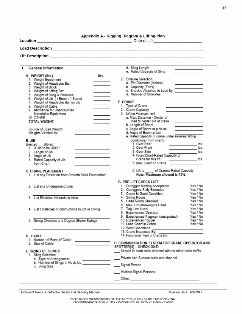
37
Document Name: Contractor Safety and Security Manual Revision Date: 6/1/2017
PAPER COPIES ARE UNCONTROLLED. THIS COPY VALID ONLY AT THE TIME OF PRINTING. THE CONTROLLED VERSION OF THIS DOCUMENT CAN BE FOUND ON SUNOCO@WORK.
Appendix A - Rigging Diagram & Lifting Plan Location ___________________________________________ Date of Lift ______________________
Load Description ____________________________________________________________________
Lift Description ______________________________________________________________________

38
Document Name: Contractor Safety and Security Manual Revision Date: 6/1/2017
PAPER COPIES ARE UNCONTROLLED. THIS COPY VALID ONLY AT THE TIME OF PRINTING. THE CONTROLLED VERSION OF THIS DOCUMENT CAN BE FOUND ON SUNOCO@WORK.
Appendix A (cont'd) -- Rigging Diagram & Lifting Plan
II. Special Instructions & Diagrams A. Special instructions or restrictions for crane, rigging, lift, etc.
B. Crane & Load placement and Rigging Diagram (use separate sheet if necessary).
REVIEW AND AUTHORIZATION
Title Print Name Signature Date
Person completing this
Lift Plan:
Lift Supervisor:
Crane Operator (s):
Rigger(s):
Signal Person(s):
Others (as needed):
( ) Owner
( ) Safety
( ) Maintenance

39
Document Name: Contractor Safety and Security Manual Revision Date: 6/1/2017
PAPER COPIES ARE UNCONTROLLED. THIS COPY VALID ONLY AT THE TIME OF PRINTING. THE CONTROLLED VERSION OF THIS DOCUMENT CAN BE FOUND ON SUNOCO@WORK.
( ) Engineering
( ) Inspection
( ) Utility company

40
Document Name: Contractor Safety and Security Manual Revision Date: 6/1/2017
PAPER COPIES ARE UNCONTROLLED. THIS COPY VALID ONLY AT THE TIME OF PRINTING. THE CONTROLLED VERSION OF THIS DOCUMENT CAN BE FOUND ON SUNOCO@WORK.
Appendix B - Standard Hand Signals

41
Document Name: Contractor Safety and Security Manual Revision Date: 6/1/2017
PAPER COPIES ARE UNCONTROLLED. THIS COPY VALID ONLY AT THE TIME OF PRINTING. THE CONTROLLED VERSION OF THIS DOCUMENT CAN BE FOUND ON SUNOCO@WORK.

42
Document Name: Contractor Safety and Security Manual Revision Date: 6/1/2017
PAPER COPIES ARE UNCONTROLLED. THIS COPY VALID ONLY AT THE TIME OF PRINTING. THE CONTROLLED VERSION OF THIS DOCUMENT CAN BE FOUND ON SUNOCO@WORK.
APPENDIX C - CRANE OPERATOR DAILY INSPECTION CHECKLIST
Crane name/number: Crane type: Crane capacity: Date of Inspection:
Location: Hour Meter:
Start:
Stop:
Total hours operated:
Operator’s Name:
INSTRUCTIONS: Check all items indicated. Inspect and indicate as Satisfactory = S, Unsatisfactory = U or Not Applicable = N/A
WALK AROUND
INSPECTION
U S N/A OPERATOR CAB INSPECTION U S N/A
Safety guards and plates Gauges Carrier frame, rotate
base
Warning & indicator lights
General hardware Control/brakes
Wire rope Visibility
Reeving Load rating charts
Block Safety devices
Hook Emergency stops
Sheeves Boom Angle/Radius Indicator
Boom/Jib MACHINERY HOUSE INSPECTION
Gantry, pendants, boom
stops
Housekeeping Walks, ladders, handrails Engine/Compressor
Wind locks, chocks, stops Leaks – Fuel, lube, oil, water
Tires, wheels, tracks Lubrication
Leaks-fuel, oil, lube,
water
Battery
Radius indicator Lights
Outrigger/locking device Glass
OPERATOR INSPECTION U S N/A Clutch linings
Area Safety Brake linings Unusual noises Electric motors
Brakes/boom/load/rotate Warning tags
Crane stability Fire Extinguisher
Test with no load
Limit Switches
COMMENTS:
OPERATOR’S SIGNATURE:
SUPERVISOR’S SIGNATURE:
NOTE: If any answers are unsatisfactory, STOP WORK and immediately discuss with Supervisor.

43
Document Name: Contractor Safety and Security Manual Revision Date: 6/1/2017
PAPER COPIES ARE UNCONTROLLED. THIS COPY VALID ONLY AT THE TIME OF PRINTING. THE CONTROLLED VERSION OF THIS DOCUMENT CAN BE FOUND ON SUNOCO@WORK.
Document Name: Contractor Safety & Security Manual Dispenser Transportation & Disposal
Document Number: HS-PRO-028
Issuing Dept: Health, Safety, and Environmental
Next Review Date: June 1, 2022
1.0 Purpose/Scope This purpose of this procedure is explain the actions to be taken when scrapping a dispenser. It is for use by anyone transporting and disposing of a used dispenser. The scope of this procedure applies to all technical service contractors providing construction and maintenance
services at Sunoco, LP Retail locations.
2.0 Definitions
None
3.0 Key Responsibilities
Sunoco Representative – Explain Sunoco’s expectations when a dispenser is to be removed, transported, and
disposed of.
Contractor Supervision – Must understand, implement, and follow the requirements of this procedure.
Contractor Workers – Understand and follow the requirements of this procedure.
4.0 Procedure/Process
4.1 Procedure for Dismantling Dispensers to Remove Gasoline
The primary job hazard is overexposure to gasoline vapors and contacts with free product. Required protective equipment includes Nitrile gloves, chemical goggles and / or face shield with goggles, and fire extinguisher.
Other recommended equipment includes forklift, explosion proof fan, gasoline collection drum, funnel, spill pads, hazardous waste drum, and rotating work platform with work area plan.
4.2 When removing gasoline from old dispensers in preparation for transportation to an approved stocking facility
or for disposal as scrap, the following instructions must be followed:
Ensure equipment is properly locked out, tagged out and verified.
Remove all dispenser doors in order to allow for ventilation.
Place flat tray or collection pan under the dispenser. Line the bottom of the collection pan/tray with spill pads.
Place the dispenser on the collection tray in a position so that the majority of work can be performed upwind.
Put on Nitrile gloves chemical goggles and / or face shield with goggles. Position fire extinguisher nearby.
Position the explosion proof fan, if needed, so that any vapors blow away from the Technician. o The fan should ideally be placed at a 45 degree angle from the dispenser when possible. o Turn the fan on.
Remove visible caps or plugs from the dispenser to allow gasoline to drain easily.
Place a small gasoline collection pan under the filter.
Remove filter(s) and pour gasoline into a remote collection can with a funnel. o Leave the filter upside down in the funnel to drain all of the gasoline. o Dispose of filter in the hazardous waste drum.

44
Document Name: Contractor Safety and Security Manual Revision Date: 6/1/2017
PAPER COPIES ARE UNCONTROLLED. THIS COPY VALID ONLY AT THE TIME OF PRINTING. THE CONTROLLED VERSION OF THIS DOCUMENT CAN BE FOUND ON SUNOCO@WORK.
Remove copper tubing and drain into the small collection pan.
Remove/disassemble the meter and drain the gasoline into the remote collection can with a funnel.
Remove strainer and catch the gasoline in the small collection pan. Immediately empty the collection pan into the remote can/funnel.
4.3 General Precautions
Always turn dispenser so that the Technician can be positioned between the fan and the work area (upwind).
Miscellaneous tubing and parts should be placed in an open drum or dumpster at a remote location so that they can continue to “air-out”.
Remove and replace pan spill pads as necessary when they are contaminated with gasoline.
When positioning the dispenser, if possible, raise the dispenser to a comfortable working level to reduce excessive bending of the back.
All work will be performed either outside or in a well-ventilated area. No work will be performed in a closed building.
All work should be performed with the intent to reduce exposure to gasoline vapors and free product. Take the time to reposition the dispenser to work in the up-wind area.
All fans must be explosion-proof.
5.0 Key Documents/Tools/Reference
None
REVISION LOG
Revision Date Document Author
Document Authorizer Revision Details
4/7/2017 T. Kocis J. Roberts Reformatting to new safety procedure format.
Consolidation and reorganizing of prior Contractor Safety
and Security Manual.

45
Document Name: Contractor Safety and Security Manual Revision Date: 6/1/2017
PAPER COPIES ARE UNCONTROLLED. THIS COPY VALID ONLY AT THE TIME OF PRINTING. THE CONTROLLED VERSION OF THIS DOCUMENT CAN BE FOUND ON SUNOCO@WORK.
Document Name: Contractor Safety and Security Manual DOT Regulations
Document Number: HS-PRO-029
Issuing Dept: Health and Safety
Next Review Date: June 1, 2022
1.0 Purpose/Scope
The purpose of this procedure is to describe Department of Transportation (DOT) regulations that Contractors must follow in their daily job performance. The scope of this procedure applies to all technical service contractors providing construction and maintenance
services at Sunoco, LP Retail Locations.
2.0 Definitions
None
3.0 Key Responsibilities
Sunoco Representative – Ensure that this procedure is communicated to the contractors.
Contractor Supervision – Ensure that this procedure is reviewed and followed by all personnel working on site.
Drivers/Workers – Review, understand, and follow these requirements and DOT requirements when working at a
Sunoco LP asset.
4.0 Procedure/Process
4.1 Drivers/Contractors are responsible for complying with all Department of Transportation regulations:
Each driver is responsible for daily hours.
Each driver is responsible for knowledge of regulations.
Each driver is responsible for all paperwork.
Each driver should refer to the latest edition of the Federal Motor Carrier Safety Regulations Pocket Book for further details.
4.2 DOT Requirements include, but are not limited to the following:
Maximum Driving and On Duty Time o Each driver must have 10 consecutive hours off-duty before returning to drive. o Maximum driving time is 11 hours. o Cannot drive after their 14th hour after the start of their shift, 16th hour once a week if the Short Haul
Exception applies. o Must take a 30 minute rest period before 8 hours if the Short Haul Exception does not apply. o Cannot drive after being on duty for 70 hours in the last 8 days or 60 hours in the last 7 days,
whichever rule applies.
Outside Inspections & Service
o Each driver must inspect and maintain all vehicles. o Any receipts for service and repair work in the vehicle must be kept in the DOT file. o Most records are required to be kept for a minimum of one year.
Daily Vehicle Condition Inspections

46
Document Name: Contractor Safety and Security Manual Revision Date: 6/1/2017
PAPER COPIES ARE UNCONTROLLED. THIS COPY VALID ONLY AT THE TIME OF PRINTING. THE CONTROLLED VERSION OF THIS DOCUMENT CAN BE FOUND ON SUNOCO@WORK.
o Every driver must conduct a Pre-Inspection before each day’s work on each vehicle operated. o A legible copy of the last vehicle inspection report is to be carried on the vehicle.
5.0 Key Documents/Tools/Reference
CFR · Title 49 – Transportation, Federal Motor Carrier Safety Administration, Parts 300 - 399
REVISION LOG
Revision Date Document Author
Document Authorizer Revision Details
5/8/2017 W. Sanicky J. Roberts Reformatting to new safety procedure format.
Consolidation and reorganizing of prior Contractor Safety
and Security Manual.

47
Document Name: Contractor Safety and Security Manual Revision Date: 6/1/2017
PAPER COPIES ARE UNCONTROLLED. THIS COPY VALID ONLY AT THE TIME OF PRINTING. THE CONTROLLED VERSION OF THIS DOCUMENT CAN BE FOUND ON SUNOCO@WORK.
Document Name: Contractor Safety and Security Manual Electrical Safety
Document Number: HS-PRO-030
Issuing Dept: Health and Safety
Next Review Date: June 1, 2022
1.0 Purpose/Scope
The purpose of this procedure is to set the requirements for working with electricity. The scope of this procedure applies to all technical service contractors providing construction and maintenance services at Sunoco, LP Retail locations.
2.0 Definitions
Arc Flash - Arc Flash is the result of a rapid release of energy due to an arcing fault between a phase and another phase, neutral or a ground. During an arc fault the air is the conductor. No one shall ever be inside the flash boundary of any equipment without training and the required PPE. Approach Boundaries - The distance a particular worker must maintain from electrical equipment. This distance can vary depending upon qualification level. Ground - A conducting connection, whether intentional or accidental, between an electrical circuit or equipment and the earth or to some conducting body that serves in place of the earth. Grounded, (Effectively) - Intentionally connected to earth through a ground connection or connections of sufficiently low impedance and having sufficient current-carrying capacity to prevent the buildup of voltages that may result in undue hazards to connected equipment or to persons. Ground Fault Circuit Interrupter (GFCI) - A device intended for the protection of personnel that functions to de-energize a circuit or portion thereof within an established period of time when a current to ground exceeds the values established for a Class A device. Qualified Worker – One who has skills and knowledge related to the construction, maintenance, and operation of the electrical equipment and installations and has received safety training on the hazards involved. Unqualified Worker – An employee with little or no training in avoiding electrical hazards and working near exposed energized parts.
3.0 Key Responsibilities
Sunoco Representative – Ensure that this procedure is communicated to the contractors.
Contractor Supervision – Ensure that this procedure is reviewed and followed by all personnel working on site.
Workers – Review, understand, and follow these requirements for working with electricity.
4.0 Procedure/Process
4.1 Basic Electrical Concepts
Like heat or light, electricity can easily flow through some materials. These materials are called conductors. Others, called insulators, have a great deal of resistance to electrical flow. All materials, even conductors, resist the flow of electricity to some degree.
The flow of electrical energy is called current. Current will only flow if a complete path or circuit is provided for it to follow. The electrical pressure that makes the current flow is voltage. A conductor connected to a voltage source is energized.

48
Document Name: Contractor Safety and Security Manual Revision Date: 6/1/2017
PAPER COPIES ARE UNCONTROLLED. THIS COPY VALID ONLY AT THE TIME OF PRINTING. THE CONTROLLED VERSION OF THIS DOCUMENT CAN BE FOUND ON SUNOCO@WORK.
The electrical resistance of a conductor can cause it to get hot when a current flows through it. There must be enough voltage applied to a conductor to overcome the conductor’s resistance before current will flow.
Electrical circuits are often grounded for safety. Grounding provides a safe path for current if a tool or its power cord is damaged.
4.2 Qualified Electrical Workers
Contractor companies who perform electrical work must follow applicable regulations and standards.
The contractor must provide their employees with the appropriate level of NFPA 70e training. The record of each person’s training must be logged in the company’s training records.
Only properly trained and qualified personnel may work on or with electricity.
4.3 Electrical Equipment
Electrical equipment shall be free from recognized hazards that are likely to cause death or serious physical harm to employees (water, open equipment, storage issues, etc.).
Electrical equipment may not be used unless the manufacture’s name, trademark, or other descriptive marking is on the equipment. Other markings shall provide voltage, current, wattage, or other ratings as necessary.
4.4 Safe Work Practices
De-energize equipment: When performing work on electrical systems or circuits that requires entering the prohibited approach boundary, the equipment shall be de-energized, locked out, and tested before work begins within boundary.
Voltage Testers and Detectors - The expected voltage of equipment must be know prior to starting work. The actual voltage must be tested to verify that it is correct. Only trained and qualified employees may perform voltage testing.
Check the Panel Legend or Index, breaker, and tag to make sure you are working on the right circuit and equipment.
Make sure that the equipment can be de-energized without affecting other equipment that may be on the same circuit.
Make sure the equipment has been put in safe condition so that it cannot be energized while it is being worked on.
Lock-out/Tag-out must be used unless performing acceptable and safe troubleshooting.
Only Qualified Personnel using proper procedures may conduct troubleshooting or work on live energized circuits.
Prepare the area where the work is to be done (such as, using rubber mats on the floor, remove any water, remove unnecessary materials, remove unnecessary personnel, etc.)
Use the proper electrical safety PPE approved for the equipment voltage. Inspect the PPE prior to use.
Check the equipment to determine what is energized and what is not.
Cover exposed energized conductors to minimize shock hazards.
Wear appropriate electrical clothing and footwear.
Do not wear metal jewelry and other metal objects that could conduct electricity.
Circuits should always be properly grounded and bonded in accordance with the current National Electric Code regulations.
To assure grounding and bonding, temporary extension cords utilized at construction sites should include the use of ground fault circuit interrupters.
Follow the “One-Hand Rule” - Work with one hand and keep the other at your side or in your pocket.” Follow the One-Hand rule whenever you work on live circuits. Otherwise, electricity passing from arm to arm may pass through vital organs, leaving you paralyzed or dead.
Avoid using metal ladders when working with or near electricity. They conduct electricity and are not suitable for work around electrical circuits and equipment.
If you see something you’re not sure about, have it checked out.
If you don’t know a procedure, ask someone who does.
Questions about electricity are never a waste of time.

49
Document Name: Contractor Safety and Security Manual Revision Date: 6/1/2017
PAPER COPIES ARE UNCONTROLLED. THIS COPY VALID ONLY AT THE TIME OF PRINTING. THE CONTROLLED VERSION OF THIS DOCUMENT CAN BE FOUND ON SUNOCO@WORK.
4.5 Personal Injuries
Burns and shock are the most common injuries caused by contact with electrical hazards. Heat produced by arcs and by the resistance of conductors can cause painful burns.
Four factors influence how severe a shock will be. o The voltage involved. Generally, as little as 30 volts is enough to push current through your body. o The amount of current available from the source. o The path the current takes through your body. A current path through your heart is more dangerous
than a path that does not pass through your heart. o The resistance of your skin. Wet skin has less resistance and will contribute to a stronger shock than
dry skin.
4.6 Responding to Electrical Emergencies
Call for emergency assistance.
Remember that you could become a victim yourself if you are not trained and knowledgeable in responding to electricity-related incidents.
Follow your company’s emergency response procedures.
Power must be turned off before touching any victims.
Victims may require cardiopulmonary resuscitation (CPR).
When personnel doing work on electrical systems, there should be personnel trained in CPR and First Aid on site.
4.7 Avoiding Electrical Hazards - When working in areas where electrical hazards may be present, the following
precautions should be taken to avoid electrical hazards.
Avoid contact with energized conductors.
Follow lockout/tagout procedures for de-energizing equipment before you work on it.
Avoid overloading circuits.
Wiring, power cords, and extension cords are rated to carry only a specific amount of current. Check the amount of current used by your equipment before you plug it in.
Use short extension cords whenever possible.
Ground Fault Circuit Interrupters (GFCI’s) must be used on all portable electric power tools.
GFCI’s shall be inspected and tested periodically as required by the manufacturer.
If GFCI’s are not used, an Assured Grounding Conductor Program must be used.
Observe and follow the special warning signs at high voltage areas. Do not enter high voltage areas without specific instructions.
Inspect cords on power tools and equipment for crushed or bare conductors and damaged plugs.
Check equipment ground connections.
Damaged equipment shall be immediately taken out of service and discarded or repaired.
Doors, guards, or covers shall be in place to protect personnel from contact with exposed energized circuits.
4.8 Overhead Power Lines
Anyone not qualified to work near exposed energized or de-energized overhead lines must stay a minimum of ten feet away from any unguarded equipment.
Vehicles and mechanical equipment must also maintain a ten-foot safe distance. This includes the bucket on the bucket truck.
Tree trimmers must be qualified and have sufficient knowledge of the construction and operation of overhead power lines in order to prevent accidentally contacting or cutting a power line.
Sites with overhead power lines shall be evaluated by the Sunoco Representative and contractor at the pre-construction meeting.
The Contractor shall contact the local utility company to arrange for their inspection of and requirements for the de-energizing/protection of any overhead power line on the site prior to the work.

50
Document Name: Contractor Safety and Security Manual Revision Date: 6/1/2017
PAPER COPIES ARE UNCONTROLLED. THIS COPY VALID ONLY AT THE TIME OF PRINTING. THE CONTROLLED VERSION OF THIS DOCUMENT CAN BE FOUND ON SUNOCO@WORK.
If a safe distance cannot be maintained (at least 10 ft.) from power lines, qualified personnel (trained utility company personnel or approved utility contractors) and appropriate equipment can be used to de-energize, isolate, and sleeve the lines.
4.9 Electrical Cords
All cords intended for temporary usage shall be rated for the actual application and work situation.
Before each period of use, the person using the cord shall carefully examine it for failure of the outer insulation, particularly at terminal points where the cord enters the plug, tool or light.
Kinking or excessive bending of the electric cord must be avoided to prevent the wire strands from breaking.
Extension and light cords must be disconnected at the end of each job unless continuous shifts are in effect.
No extension cord, including electrical adapter ("Pig Tail"), is to be used as a permanent installation.
When lighting is used inside a confined space, cords should be run through openings other than those being used for entering or exiting if possible. If not possible, then cords should be placed as "out of the way" as possible.
Cords shall not be permitted as a substitute for fixed wiring.
Cords shall not be run thru holes in walls, ceilings, window, doorways, floors, etc. unless suitable protection against damage and tripping is provided.
Cords should not be run in places where they can be run over by a vehicle, or become a tripping hazard. If they must be run in these areas, adequate protection from damage and tripping must be provided.
Cords shall be run overhead, bridged underneath, or otherwise kept out of walkways whenever feasible.
Temporary wiring cannot exceed more than 90 days.
5.0 Key Documents/Tools/Reference
OSHA CFR 1910 Subpart S – Electrical OSHA CFR 1910.137 – Electrical Protective Devices OSHA CFR 1926 Subpart K – Electrical OSHA CFR 1926 Subpart V– Power Transmission and Distribution NFPA 70 National Electric Code NFPA 70E Handbook for Electrical Safety in the Workplace NESC National Electric Safety Code
REVISION LOG
Revision Date Document Author
Document Authorizer Revision Details
5/17/2017 T. Kocis J. Roberts Reformatting to new safety procedure format.
Consolidation and reorganizing of prior Contractor Safety
and Security Manual.

51
Document Name: Contractor Safety and Security Manual Revision Date: 6/1/2017
PAPER COPIES ARE UNCONTROLLED. THIS COPY VALID ONLY AT THE TIME OF PRINTING. THE CONTROLLED VERSION OF THIS DOCUMENT CAN BE FOUND ON SUNOCO@WORK.
Document Name: Contractor Safety and Security Manual Emergency Posting and Reporting
Document Number: HS-PRO-031
Issuing Dept: Health and Safety Department
Next Review Date: June 1, 2022
1.0 Purpose/Scope
To outline at a minimum, emergencies that need to be reported to Sunoco, as well as to ensure all employees at a job site are aware of said emergencies and appropriate response.
The scope of this procedure applies to all technical service contractors providing construction and
maintenance services at Sunoco, LP Retail locations.
2.0 Definitions Type of Emergencies – Examples are, but not limited to the following: Gasoline leaks and / or spills greater
than five gallons, robbery, or other criminal activities, fires or any employee, sub – contractor injury or fatality (First Aid on site, Medical off site at an Emergency Room, Clinic, Doctor’s Office, etc.).
3.0 Responsibility
Construction Engineer
Ensure the Contractor is aware to notify the construction engineer of any and all emergencies.
Communicates the type of emergency to the appropriate internal Sunoco Department.
Assists with Sunoco investigation.
Contractor
The Contractor will have in place and readily available emergency procedures as well as appropriate postings.
Endure all employees and sub-contractors are aware and understand these emergency procedures.
Cooperate with Sunoco during the investigative process.
Post where visual to all employees an Emergency Contact List. (Appendix A – Sample Posting) Subcontractor
Will comply with all emergency procedures.
Report any type of emergency immediately to his or her immediate on site supervisor.
Cooperate with Sunoco during the investigative process.
4.0 Procedure/Process
In case of emergency, all contractor employees and sub-contractors need to know whom they are to
immediately notify. Sunoco requires the following:
Posting of a sign or signs at the project site listing the following: o Contractor’s name and 24 hour phone number. o Police and Fire Emergency Number. o Location and directions of the nearest Hospital Emergency Room and Clinic. o Sunoco’s Central Monitoring Facility (CMF).
52
Document Name: Contractor Safety and Security Manual Revision Date: 6/1/2017
PAPER COPIES ARE UNCONTROLLED. THIS COPY VALID ONLY AT THE TIME OF PRINTING. THE CONTROLLED VERSION OF THIS DOCUMENT CAN BE FOUND ON SUNOCO@WORK.
Emergency response information requested by the Owner’s Representative.
Each site is required to have turn by turn directions to the nearest hospital on site in the vent that another contractor onsite must transport the injured worker to the hospital
Sunoco’s Central Monitoring Facility (CMF) and the Owner’s Representative shall be called in an emergency.
o The Contractor shall continue to make attempts to contact the appropriate Owner’s Representative until actual verbal contact is made. Leaving a message is not sufficient.
5.0 Key Documents/Tools/References
Appendix A – Sample Emergency Contact Job Site Posting
REVISION LOG
Revision Date Document Author
Document Authorizer Revision Details
5/17/2017 L. Pontani J. Roberts Reformatting to new safety procedure format. Consolidation and reorganizing of prior Contractor Safety and Security Manual.

53
Document Name: Contractor Safety and Security Manual Revision Date: 6/1/2017
PAPER COPIES ARE UNCONTROLLED. THIS COPY VALID ONLY AT THE TIME OF PRINTING. THE CONTROLLED VERSION OF THIS DOCUMENT CAN BE FOUND ON SUNOCO@WORK.
Appendix A – Sample Emergency Contact Job Sit Posting
JOB SITE LOCATION: __________________________ COMPANY NAME: ______________________________
KEEP THIS INFORMATION READILY AVAILABLE ON EACH JOB SITE
POLICE
FIRE
AMBULANCE
JOB SITE SUPERVISOR / MANAGER
INJURY INSTRUCTIONS
Minor First Aid Treatment
If you sustain an injury or are involved in an accident requiring minor first aid treatment:
Inform your Supervisor immediately.
Use the first aid kit at the job site.
Provide details for the completion of the accident investigation report.
Non-Emergency Medical Treatment
For non-emergency work-related injuries requiring professional medical assistance, (treatment by a doctor, ER or clinic), your supervisor will assist you. If you sustain an injury requiring treatment other than first aid:
Inform your Supervisor immediately
Available Medical Facilities
Provide details for the completion of the accident investigation report.
Emergency Medical Treatment
If you sustain a severe injury requiring emergency treatment:
Call 911 for help and seek assistance from a co-worker.
Inform your Supervisor immediately.
Provide details for the completion of the accident investigation report
LIST NAME, ADDRESS AND PHONE NUMBER OF NEAREST HOSPITAL AND CLINIC
(URGENT CARE CENTER)

54
Document Name: Contractor Safety and Security Manual Revision Date: 6/1/2017
PAPER COPIES ARE UNCONTROLLED. THIS COPY VALID ONLY AT THE TIME OF PRINTING. THE CONTROLLED VERSION OF THIS DOCUMENT CAN BE FOUND ON SUNOCO@WORK.
Document Name: Contractor Safety & Security Manual Emergency Fuel Shutoff Operation
Document Number: HS-PRO-032
Issuing Dept: Health and Safety
Next Review Date: June 1, 2022
1.0 Purpose/Scope
The purpose of this procedure is to describe the operating procedures for Fuel Dispenser Emergency Shut-Off Valves.
The scope of this procedure applies to all technical service contractors providing construction and maintenance
services at Sunoco, LP Retail locations.
2.0 Definitions
Fuel Dispenser Emergency Shut-Off – This is a safety mechanism used to manually shut-down the flow of fuel
to all fuel dispensers at a site.
3.0 Key Responsibilities
Sunoco Representative – A member of the Retail Engineering, Construction and Maintenance Management Team
is responsible for management and implementation of this procedure. Retail Engineering, Construction and
Maintenance employees and contractors are responsible for knowledge of and adherence to this procedure.
Contractor Supervision – Ensure all of their employees are informed of the contents of this procedure and that their
employees will follow the requirements of this procedure.
Contractor Workers – Review, understand, and follow the requirements in this procedure.
4.0 Procedure/Process
4.1 When use of the Emergency Shut-Off Valve on fuel dispensers is required, the instructions on the following
procedure must be followed.
4.1.1. In the event of a Gasoline Spill or Fire at an active store, proceed with the following actions:
The flow of fuel should be immediately shutoff. This means activating the Emergency Fuel Shutoff Switch (E-Stop).
Immediately notify store personnel of the event.
Example images of Emergency Stop Buttons are listed below in Section 5.0.
4.1.2 If an E-Stop button is not in place, the circuit breakers for the submersible turbine pumps and dispensers should be utilized as the primary emergency shut-off device. This should be done by an authorized person from the store or electrician.

55
Document Name: Contractor Safety and Security Manual Revision Date: 6/1/2017
PAPER COPIES ARE UNCONTROLLED. THIS COPY VALID ONLY AT THE TIME OF PRINTING. THE CONTROLLED VERSION OF THIS DOCUMENT CAN BE FOUND ON SUNOCO@WORK.
5.0 Key Documents/Tools/Reference
Examples of Emergency Shutoff Buttons:
REVISION LOG
Revision Date Document Author
Document Authorizer Revision Details
5/17/2017 T. Kocis J. Roberts Reformatting to new safety procedure format.
Consolidation and reorganizing of prior Contractor Safety
and Security Manual.

56
Document Name: Contractor Safety and Security Manual Revision Date: 6/1/2017
PAPER COPIES ARE UNCONTROLLED. THIS COPY VALID ONLY AT THE TIME OF PRINTING. THE CONTROLLED VERSION OF THIS DOCUMENT CAN BE FOUND ON SUNOCO@WORK.
Document Name: Contractor Safety and Security Manual Excavation
Document Number: HS-PRO-033
Issuing Dept: Health and Safety
Next Review Date: June 1, 2022
1.0 Purpose/Scope
This procedure describes the actions to be taken prior to and during excavations in order to prevent incidents involving excavations. The scope of this procedure applies to all technical service contractors providing construction and maintenance
services at Sunoco, LP Retail locations.
2.0 Definitions
Competent Person - One who is capable of identifying existing and predictable hazards in the surrounding, or
working conditions which are unsanitary, hazardous, or dangerous to employees and who has authorization to
take prompt corrective measures to eliminate them. The Competent Person shall have successfully completed
training to be deemed an Excavation Competent Person.
Excavation - Any man-made cut, cavity, trench or depression in an earth surface, formed by earth removal.
Excavation Work - The use of hand tools, powered equipment or explosives in the movement of earth, rock, or
other material. Excavation includes but is not limited to anchoring, auguring, backfilling, digging, ditching, drilling,
driving-in, grading, plowing-in, and trenching.
Excavator - Any individual in physical control of powered equipment when being used to perform excavation work. Faces or Sides - The vertical or inclined earth surfaces formed as a result of excavation work. Hazardous Atmosphere - An atmosphere which by reason of being explosive, flammable, poisonous, corrosive, oxidizing, irritating, oxygen deficient, toxic, or otherwise harmful, may cause death, illness, or injury. One-Call System - A communication and coordination system used to obtain location information for underground utilities located in a state. The standard phone number is 811. Protective System - A method of protecting employees from cave-ins, material that could fall or roll from an
excavation, or from the collapse of adjacent structures. Protective Systems include support systems, sloping and
benching systems, shield systems and other necessary protection.
Shield - A structure that is able to withstand the forces imposed on it by a cave-in and thereby protects
employees within the structure. Shields can be permanent or portable. Shields in trenches are usually referred
to as trench boxes.
Shoring - A structure such as a metal hydraulic, mechanized or timber shoring system that supports the sides of
an excavation and which is designed to prevent cave-ins.
Sloping - A method of protecting employees from cave-ins by excavating the soil so that the sides are inclined
away from the excavation. The angle of incline varies with different factors such as soil type, environmental
conditions of exposure and application of surcharge loads.
Trench - A narrow excavation made below the surface of the ground. In general, depth is greater than width but
the width of a trench (at the bottom) is not greater than 15 feet.

57
Document Name: Contractor Safety and Security Manual Revision Date: 6/1/2017
PAPER COPIES ARE UNCONTROLLED. THIS COPY VALID ONLY AT THE TIME OF PRINTING. THE CONTROLLED VERSION OF THIS DOCUMENT CAN BE FOUND ON SUNOCO@WORK.
3.0 Key Responsibilities
Sunoco Representative – Ensure that this procedure is communicated to the contractors doing excavation work.
Ensure that excavations are done under the direction of a trained Excavation Competent Person. Ensure that the
requirements for excavations are followed.
Contractor Supervision – Ensure that a One Call is made well in advance of the excavation work. Ensure that all
requirements for excavations are followed (OSHA, Sunoco, etc.). Ensure that a trained Excavation Competent
Person is on site for excavation work and personnel entries into Excavations.
Workers – Review, understand, and follow these requirements and OSHA requirements for excavations.
4.0 Procedure/Process
4.1 Site Safety Review Before Work Begins
The excavation site shall be reviewed by the Competent Person to identify existing or suspected hazards such as overhead power lines, toxic or flammable conditions, protective equipment required, and any engineering controls necessary to reduce or eliminate them.
A One-Call must be done.
4.2 Excavation Competent Person Inspections
The Excavation Competent Person will perform daily inspections of the excavation, adjacent areas, and protective systems (prior to the start of work and as needed throughout the shift).
Inspections shall also be made after every rainstorm or other hazard increasing occurrence. The Excavation Competent Person must document the inspection on an Excavation Inspection Form when
work is being conducted inside of the excavation. In excavations less than 5 feet deep where a protective system is not installed, the Excavation Competent
Person must examine the ground to ensure there is no indication of potential cave-in. Where the competent person finds evidence of a situation that could result in a possible cave-in,
indications of failure of protective systems, hazardous atmospheres, or other hazardous conditions, exposed employees shall be removed from the hazardous area until the necessary precautions have been taken to ensure their safety.
An example of the Excavation Inspection Form can be found in Appendix A.
4.3 Confined Space
An excavation that is four (4) feet deep or greater with limited or restricted access and egress is a confined space and is subject to entry permit requirements of the Confined Space Safety Procedure (unless the space can be properly declassified as a Non-Permit Required Confined Space).
The Excavation Competent Person must, at minimum, physically view each excavation, regardless of depth, to ensure even shallow excavations do not pose a collapse hazard to workers. In such cases these shallow excavations (less than four feet) need to be considered confined spaces. The location and position of the worker's body shall be considered in these cases.
Personnel entering confined space excavations shall wear a full body harness to aid in removal if incapacitated.
4.4 Access and Egress
Trench excavations four feet or deeper shall have stairways, ramps, ladders (ladder must exceed 3 feet past the top of the excavation), or other safe means of egress. These shall be located so no employee must travel more than 25 feet laterally.
Employees shall not be lifted or lowered into a trench excavation by equipment that is not specifically designed for that purpose.
The structural design for ramps shall meet all structural design criteria including the following requirements: o When constructed of two or more structural members, the members must be connected together to
prevent displacement.

58
Document Name: Contractor Safety and Security Manual Revision Date: 6/1/2017
PAPER COPIES ARE UNCONTROLLED. THIS COPY VALID ONLY AT THE TIME OF PRINTING. THE CONTROLLED VERSION OF THIS DOCUMENT CAN BE FOUND ON SUNOCO@WORK.
o Structural members must be of uniform thickness. o Ramps used in place of steps must have cleats or other means (e.g., surface treatments - non-slip
paints, etc.) to prevent slipping. o Cleats or other appropriate means used to connect the structural members must be attached to the
bottom of the members or by other method to prevent tripping.
4.5 Protection from Falling Material
Employees are not permitted under loads handled by lifting or digging equipment. Employees are required to stand away from any vehicle being loaded or unloaded to avoid being struck by
spillage or falling materials. Drivers are not allowed in the truck cab during loading unless the cab is designed to protect the driver from
falling loads. Personnel must be protected from any loose rock or soil that could pose a hazard by falling or rolling from
the excavation face. This can be done by sloping, protective barricades, or other equivalent means. Personnel must be protected from excavated materials (spoil pile) or other materials and equipment that
could pose a hazard by falling or rolling into excavations. Protection shall be provided by placing and keeping excavated materials or equipment at least 2 feet from
the edge of the excavation. Spoil dirt should be piled at no steeper angle than that of the excavation.
4.6 Protection from Vehicular Traffic and for Pedestrians
Excavations shall be barricaded to make them visible and to prevent vehicles and pedestrians from accessing the excavation.
Where possible, barricades should be placed within 10 feet of the excavation edge. When the excavations are six (6) feet or deeper, it is a Fall Prevention situation. Barricades must be
constructed of materials able to withstand 200 lbs. of force in any direction. Barricades shall remain around the excavation until backfilling.
If lighting is not adequate in the excavation area, reflective or other high visibility material shall be used to barricade the excavation.
Excavations within or adjacent to roadways must have a dedicated person to direct traffic around the excavation when work is occurring at or within the excavation site. This person shall be equipped with a warning vest and equipment to direct traffic such as flags and/or a stop sign.
4.7 Air Monitoring
The atmosphere in excavations will be tested prior to entry.
The minimum monitoring should be: Oxygen, Explosive Gases (LEL), and Carbon monoxide. Monitoring must be documented.
Additional monitoring will be based on site conditions and if some sort of contamination is suspected. Examples would include a known history of spills or leaks, the discovery of stained or discolored soil, or evidence of former piping.
Periodic or continuous testing will be performed based on initial test results and the type of hazard posed.
Provide engineering controls, i.e. ventilation, or PPE to assure that workers are not exposed to hazardous atmospheres.
Observe the placement of equipment (welders, compressors, light towers, etc.) to avoid exhaust gases or other contaminants from entering the excavation. Continually test for Carbon monoxide if any sources of exhaust gas are within 50 feet of the excavation.

59
Document Name: Contractor Safety and Security Manual Revision Date: 6/1/2017
PAPER COPIES ARE UNCONTROLLED. THIS COPY VALID ONLY AT THE TIME OF PRINTING. THE CONTROLLED VERSION OF THIS DOCUMENT CAN BE FOUND ON SUNOCO@WORK.
4.8 Soil Contamination
Before starting an excavation, the potential for soil contamination must always be considered. Characterization of the soil should be performed if feasible. Check with the Environmental Department for past records or assistance.
4.9 Emergency Rescue
Emergency rescue services must be planned ahead of entry into a confined space.
A properly trained Emergency Response Team (ERT) must be readily available to respond to an emergency rescue situation.
Emergency rescue equipment, such as breathing apparatus, a safety harness and line, or a basket stretcher, shall be readily available where hazardous atmospheric conditions exist or may reasonably be expected to develop during work in an excavation.
4.10 Water Accumulation Protection
Personnel shall not work in excavations where water has or is accumulating unless special precautions have been taken.
These precautions may include but are not limited to, proper water removal equipment, special support or shield systems to protect from cave-ins, etc.
4.11 Stability of Adjacent Structures
Support systems, such as shoring, bracing, underpinning, etc. shall be used when an excavation threatens the stability of adjoining buildings, walls, or other structures.
Excavations which go below the base or footing of any foundation or retaining wall that could pose a hazard to personnel shall only be permitted when: o A support system is provided or o The excavation is in stable rock or o A registered professional engineer determines the structure will not pose hazard to personnel or o A registered professional engineer has approved the determination that the structure is far enough away
from the excavation to be unaffected. Sidewalks, pavements and structures shall not be undermined unless a support system or other protection
method is provided to protect employees from the possible collapse of such structures. 4.12 Protective Systems
A Protective System shall be used whenever personnel will be working in an excavation that is 5 feet or deeper, or if an Excavation Competent Person determines there is a potential of cave-in, regardless of the depth.
Any Protective System must meet OSHA requirements. Any sloping or benching greater than 20 feet deep shall be designed by a registered professional
engineer.
5.0 Key Documents/Tools/Reference
29 CFR 1926 Subpart P: Excavations Appendix A - Sample Excavation Inspection Form
REVISION LOG
Revision Date Document Author
Document Authorizer Revision Details
5/17/2017 T. Kocis J. Roberts Reformatting to new safety procedure format.
Consolidation and reorganizing of prior Contractor Safety
and Security Manual.

60
Document Name: Contractor Safety and Security Manual Revision Date: 6/1/2017
PAPER COPIES ARE UNCONTROLLED. THIS COPY VALID ONLY AT THE TIME OF PRINTING. THE CONTROLLED VERSION OF THIS DOCUMENT CAN BE FOUND ON SUNOCO@WORK.
Appendix A – Sample Excavation Inspection Form
Date: Location of Excavation: Contractor Company:
Name of Excavation Competent Person(s):
DATE
1 Excavation inspected daily by Excavation Competent Person? 2 One Call has been done?
3 Excavation Inspection Form Posted at the excavation?
4 Excavation properly barricaded for vehicles and pedestrians?
5 Traffic in area is controlled and directed away from excavation
operation?
6 Is safe access and egress provided?
7 Spoils and equipment are at least 2 feet away from edge of
excavation?
8 Area clear of falling materials trees, large rocks, or other hazards?
9 Is excavation less than 4 feet deep? If NO, excavation is a confined
space. Follow Confined Space requirements.
10 Have Emergency Responders been notified of the Confined Space
Entry and are they able to respond appropriately?
11 Has the atmosphere been determined to be free of hazardous
atmospheres?
12 Is the excavation free of liquid accumulation?
13 Is the proper liquid removal in place?
14 Is the excavation free of caving or sloughing of soil since previous
inspection?
15 Is soil or rock free of evidence of significant cracking around the
excavation?
16 Are surrounding structures, objects, buildings, poles, etc. properly
protected from being impacted by the excavation?
17 Is excavation less than 5 feet? If NO, sloping shoring, or other
protective system is required.
18 Type of Protective System being used? Is it
secure?
19 Protective System plan includes adequate safety factor to allow for
equipment actually being used (e.g. heavy equipment outside the
excavation)?
Comments/Remarks:
Excavation Competent Person Initials

61
Document Name: Contractor Safety and Security Manual Revision Date: 6/1/2017
PAPER COPIES ARE UNCONTROLLED. THIS COPY VALID ONLY AT THE TIME OF PRINTING. THE CONTROLLED VERSION OF THIS DOCUMENT CAN BE FOUND ON SUNOCO@WORK.
Document Name: Contractor Safety and Security Manual Fall Protection
Document Number: HS-PRO-034
Issuing Dept: Health and Safety
Next Review Date: June 1, 2022
1.0 Purpose/Scope
The purpose of this procedure is to set the requirements to protect employees from fall injuries when working in
elevated positions. This procedure defines requirements to inform all personnel when fall protection is required.
The scope of this procedure applies to all technical service contractors providing construction and maintenance
services at Sunoco, LP Retail locations.
2.0 Definitions Anchor Point- A secure point of attachment of lifelines, lanyards or deceleration devices. Competent Person- Someone who has been qualified as a result of receiving fall protection training and additional specialized instruction on equipment instruction. This person may conduct Personal Fall Protection Equipment (PFPE) inspections beyond the “before use” check. Full Body Harness- Straps which may be secured about the employee in a manner that will distribute the fall arrest forces over the thighs, pelvis, waist, chest and shoulders with means for attaching it to other compenents of a personal fall arrest system. Guardrail System- Top and mid railings on flat working platforms which are used as a barrier to prevent employees from falling to lower levels. Lanyard- The connector part of fall protection equipment that is made of synthetic, wire rope or strap. Lanyard must have double latch self locking snap hook at each end for connecting the body harness to a lifeline or anchor point. When connected directly to an anchor point the lanyard shall have a built in decleration device. Personal Fall Protection Equipment (PFPE)- Usually consists of a full body harness and lanyard (with double latch self locking snaphooks and build in deceleration device). This equipment is used in conjunction with an anchor point to arrest a worker in a fall from an elevated working area. Qualified Person- One who has been properly trained and qualified in the use of Personal Fall Protective Equipment. Self Retracting Lanyard- (also known as self-retracting lifeline)- A deceleration device that contains a drum-wound line that may be slowly extracted from, or retracted into, the drum under slight tension during normal worker movement, and which, after onset of a fall, automatically locks the drum and arrests the fall. Snap Hook- A connector comprised of a hook shaped member with a normally closed keeper, or similar arrangement, which may be opened to permit the hook to receive an object and, when released, automatically closes to retain the object. 3.0 Key Responsibilities
Sunoco Representative – Ensure that this procedure is communicated to the contractors.
Contractor Supervision – Ensure that this procedure is reviewed and followed by all personnel working on site.
Workers – Review, understand, and follow these requirements.

62
Document Name: Contractor Safety and Security Manual Revision Date: 6/1/2017
PAPER COPIES ARE UNCONTROLLED. THIS COPY VALID ONLY AT THE TIME OF PRINTING. THE CONTROLLED VERSION OF THIS DOCUMENT CAN BE FOUND ON SUNOCO@WORK.
4.0 Procedure/Process
4.1 General Procedures
Fall protection shall be worn in the following areas/situations, but not limited to: o Man lifts (high rise/reach) in use and in transit (i.e. when driving). o Ladders (when used as a work platform). o When working over 6’ in height. o When working within 5’ of unprotected roof edge.
When PFPE is used they shall be secured properly to anchorage points that are capable of supporting a static load of 5,000 pounds per person.
Scaffolding members are not to be used as anchor points unless they are designed and built to support the 5,000 pound anchor point requirement.
PFPE shall be rigged to minimize the free fall distance, but in no case is free fall distance to exceed 6 feet. In addition, the deceleration distance must be limited to 3.6 feet and the personal fall protection system must allow for an unobstructed fall.
Before walking onto roofs, tanks, other structures, etc. the strength and structural integrity of working surfaces must be inspected to ensure that the stability of the walking area is stable.
Holes in walking surfaces shall be covered or have a guardrail installed around the perimeter.
4.2 Equipment
Only fall protection devices that meet OSHA requirements may be used by contractors on site.
The use of body belts is prohibited; only full body harnesses may be worn for body support.
All lanyards shall be equipped with locking snap hooks.
Newly constructed guardrail system members must meet load and physical installation requirements as defined in OSHA 1926.502(b). the key provisions are as follows:
o Top rail must be 42” high +/- 3”. o Mid rail must be half the distance between the top rail and the working surface. o Guardrails must withstand 200 pound force with no more than 3” deflection. o Toe boards shall be installed and fastened at the working level. Toe boards shall be 4” nominal in
vertical height.
Lanyards or retracting lifelines must be connected to D-ring on full body harness by using locking snap hook of locking carabineer.
Knots shall not be tied in lanyards for any reason.
Full body harnesses and lanyards shall be stored in a location not affected by weather or chemicals.
4.3 Anchorage
Anchorage points shall be: o A point of suitable strength to which a worker can secure their lanyard and be capable of
Withstanding 5,000 pounds of static load in a downward direction. o Independent of the work surface whenever possible. o As high as possible, preferably at or above the shoulder level, (unless designed otherwise
such as in a high-reach). o Ideally located directly above the worker to avoid the possibility of swinging into an object during a fall.
If the only suitable anchorage point is lower than shoulder level, take steps to limit potential free fall distance by crouching, sitting, using a shorter lanyard, etc. Inspect to ensure that there is enough free fall distance to eliminate collision with other objects.
When elevated work involves travel while overhead, anchor points shall be used throughout the entire time the worker is exposed to a fall hazard. This may require the use of two lanyards, so that the one can be moved to another anchor point while the contractor is still protected.
Wire form anchorage connectors shall not be used for personal fall arrest systems.

63
Document Name: Contractor Safety and Security Manual Revision Date: 6/1/2017
PAPER COPIES ARE UNCONTROLLED. THIS COPY VALID ONLY AT THE TIME OF PRINTING. THE CONTROLLED VERSION OF THIS DOCUMENT CAN BE FOUND ON SUNOCO@WORK.
4.4 Inspection
All fall protection equipment must be inspected by the user before each use. Defective or suspect equipment shall be removed from service and disposed of.
The inspection of fall protection shall include inspecting for: o Cuts ,tears, abrasions o Mold/Mildew o Hardening o Burns o Chemical stains o Tightness of any grommets or rivets o Stitching must be intact o Shock absorber must not be activated o All buckles, snap hooks and D-rings must all function properly
Manufacturer recommendations for inspection of fall protection harnesses shall be followed. 4.5 Training
All contractors who have the potential to be exposed to fall hazards shall be trained by the contracting organization as to what their responsibilities are in accordance with this procedure.
Training of this procedure shall be completed on an annual basis, as well as periodically. The contracting organization will be responsible for coordinating this training. The training shall include, but not be limited to: o Selection and safe use of equipment. o Proper anchoring techniques and locations. o Estimation of free fall distance. o Inspection and storage of fall protection equipment.
5.0 Key Documents/Tools/Reference 29 CFR 1910 Subparts:
D, Walking and Working Surfaces.
F, Powered Platforms, Man lifts and Vehicle Mounted Work Platforms.
I, Personal Protective Equipment. 29 CFR 1926 Subparts:
E, Personal Protective and Life Saving Equipment.
I, Tools, Hand and Powered.
REVISION LOG
Revision Date Document Author
Document Authorizer Revision Details
5/17/2017 B. Drager J. Roberts Reformatting to new safety procedure format.
Consolidation and reorganizing of prior Contractor Safety
and Security Manual.

64
Document Name: Contractor Safety and Security Manual Revision Date: 6/1/2017
PAPER COPIES ARE UNCONTROLLED. THIS COPY VALID ONLY AT THE TIME OF PRINTING. THE CONTROLLED VERSION OF THIS DOCUMENT CAN BE FOUND ON SUNOCO@WORK.
Document Name: Filter Changing and Disposal
Document Number: HS-PRO-035
Issuing Dept: Environmental, Health and Safety
Next Review Date: June 1, 2022
1.0 Purpose/Scope
The purpose of this procedure is to explain the safe operating procedures for changing gasoline, diesel, kerosene, or E-85 dispenser filters. The scope of this procedure applies to all technical service contractors working providing construction and
maintenance services at Sunoco, LP Retail locations.
2.0 Definitions
None
3.0 Key Responsibilities
Sunoco Representative – Ensure that this procedure is communicated to the contractors.
Contractor Supervision – Ensure that this procedure is reviewed and followed by all personnel working on site.
Workers – Review, understand, and follow these requirements when changing filters.
4.0 Procedure/Process
4.1 Filter Changing: This procedure describes the step-by-step task of changing dispenser filters. Each step described below must be followed to ensure the safety of people, property, and the environment. The priority while changing dispenser filters is employee safety; following the steps below will ensure minimal exposure to petroleum based product and vapors.
It is the responsibility of all personnel to report any skin exposures to petroleum-based products or other related injuries/illnesses to their supervisor immediately. The supervisor must immediately report the situation to his/her Sunoco contact.
4.1.1 Follow Barrier Protection procedure to secure the dispenser and put on the required personal
protective equipment: Hand protection, eye protection, face protection, etc. 4.1.2 Remove both dispenser covers to increase ventilation. 4.1.3 Close ALL crash valves to stop product flow to the dispenser. 4.1.4 Try to position yourself upwind in order to reduce exposure to petroleum vapors. 4.1.5 Activate the dispenser and squeeze the nozzle trigger and dispense product into a container, such as
a calibration can. This will verify that the crash valve is operational. 4.1.6 Contractor shall place a fuel/hydrocarbon absorbent pad under the dispenser filter area to catch any
spray or drips from the filter changing process. Contractor must remove any fuel product spilled from the dispenser area with a fuel/hydrocarbon absorbent pad. Contractor must not leave any remaining fuel product in the dispenser sump/dispenser pan area. Contractor must properly dispose of fuel/hydrocarbon absorbents.
4.1.7 Slowly loosen the filter and let the product collect in a small container under the filter. Dump the
product into a container (Note: you can use the calibration can).

65
Document Name: Contractor Safety and Security Manual Revision Date: 6/1/2017
PAPER COPIES ARE UNCONTROLLED. THIS COPY VALID ONLY AT THE TIME OF PRINTING. THE CONTROLLED VERSION OF THIS DOCUMENT CAN BE FOUND ON SUNOCO@WORK.
4.1.8 Slowly remove the emptied filter and place it upside-down in a closed collection can where it can drain
and product can be collected. 4.1.9 Verify the old filter gasket is removed. 4.1.10 Use a permanent marker to mark the “Installed Date” and “Installer’s Initials” on the new filter. 4.1.11 Oil the O-ring of the new filter before installation. 4.1.12 Tighten the new filter in place. Repeat all steps for each filter. 4.1.13 Open the crash valve. 4.1.14 Remove air in the lines by squeezing the trigger nozzle and dispense product into a container. 4.1.15 Check for leaks at the filter. 4.1.16 Replace dispenser covers. Repeat all steps for each dispenser. 4.1.17 Discard filters in accordance with local environmental regulations at each service station. See
Section 4.3 for Spent Dispenser Filter Management. 4.1.18 Contractors should take their time to perform each step safely, to prevent spilling product, and to
prevent vapor exposure. 4.1.19If product comes in contact with skin or clothing, the contractor should change clothes (if clothing was
contaminated) and wash the exposed skin area with soap and water as soon as possible. The contractor is required to notify his/her supervisor of this incident.
4.2 Training: Contractors that will be performing this task of changing and disposing of fuel filters must be
provided a copy of this procedure and be trained on how to properly perform the steps. 4.3 Spent Dispenser Filter Management
4.3.1 Spent petroleum-based dispenser filters that have been in service, including ethanol service, are Toxicity Characteristic Hazardous Waste for Benzene (D018). Below is a summary of Conditionally Exempt Small Quantity Generator-State Specific Requirements.
4.3.2 Assumptions/Conditions for the spent dispenser filter management.
Conditionally Exempt Small Quantity Generator -The service station generates no more than a total of 100kg (roughly 220 pounds) of hazardous wastes in a calendar month. This would include all hazardous waste generated. However, the amounts of used oil or universal waste lamps or batteries are not included in the 220 pounds monthly limit (as long as the lamps are managed as universal waste). If a station generates greater than the 220 pounds per month the Conditionally Exempt Small Quantity Generator (CESQG) option is not available, and the station must follow more stringent small quantity generator (SQG) or large quantity generator (LQG) requirements. However, the scrap metal option is still available even if a facility is a small quantity or large quantity generator.
All spent filters have been sufficiently drained of free liquids. Neither the CESQG option of disposal with the municipal trash nor the scrap metal destined for recycling options allow filters to contain free liquids or have liquids dripping from them.

66
Document Name: Contractor Safety and Security Manual Revision Date: 6/1/2017
PAPER COPIES ARE UNCONTROLLED. THIS COPY VALID ONLY AT THE TIME OF PRINTING. THE CONTROLLED VERSION OF THIS DOCUMENT CAN BE FOUND ON SUNOCO@WORK.
CESQG Option – If the federal CESQG option is available in the state the service station is located and the state allows disposal of drained filters in the municipal trash, that is the most cost effective and recommended option.
4.3.3 State Summaries
Scrap Metal Destined for Recycling States:
o California o Connecticut o Delaware o District of Columbia o Illinois o Maine o Maryland o Massachusetts o New Hampshire o Ohio o Pennsylvania o Rhode Island o Vermont o Virginia o West Virginia
Disposed of with Municipal Waste States: (As long as CESQG)*
o Alabama o Arizona o Florida o Georgia o Indiana o Kansas** o Michigan o New Jersey o New York o North Carolina o South Carolina o Tennessee o Texas
Note: *If SQG or LQG, then the Spent Dispenser Filters should be managed under the Scrap Metal
Destined for Recycling Program. ** Kansas CESQGs are limited to 55 pounds per month.
4.3.4 CESQG Management of Spent Gasoline Dispenser Filters
Spent dispenser filters must be properly drained prior to recycling or disposal. Properly drained means that there are no liquids dripping from the filters. In this condition, spent dispenser filters may be managed as Conditionally Exempt Small Quantity Generator, “CESQG”, and Hazardous Waste D018. As a CESQG one cannot generate more than 220 pounds of hazardous waste in a calendar month. This would include all hazardous waste generated, however, the amounts of used oil or universal waste lamps or batteries are not included in the 220 pounds monthly limit. CESQG’s must keep records of all hazardous wastes generated to show less than 220 pounds per month. A form has been attached in Appendix A to assist you in keeping track of, and documenting the amount of wastes generated at the service station. If a station generates greater than 220

67
Document Name: Contractor Safety and Security Manual Revision Date: 6/1/2017
PAPER COPIES ARE UNCONTROLLED. THIS COPY VALID ONLY AT THE TIME OF PRINTING. THE CONTROLLED VERSION OF THIS DOCUMENT CAN BE FOUND ON SUNOCO@WORK.
pounds per month, the CESQG option is not available, and the station must follow more stringent small quantity or large quantity generator requirements.
4.3.5 Scrap Metal Destined for Recycling Option
In states that do not allow CESQG’s to place hazardous waste in the municipal trash, the spent dispenser filters will be managed as scrap metal destined for recycling. For this option, all spent filters must be sufficiently drained of free liquids. Only spent filters are to be placed in the containers and the containers are to be closed except when adding filters. The containers will have a small amount of absorbent material placed at the bottom to absorb any small drips of fuel that may be released from the filters during transportation. The containers are to have labels with the words “Scrap Metal Destined for Recycling”. Include the DOT Shipping Description (Flammable Solids N.O.S. 4.1 UN1325), and the service station’s name, address and EPA ID number. An example of the label is attached in Appendix B to this document for reference. Containers will be delivered already with absorbents and labels. Containers will be picked up when full or at least once per year. The filters will be transported to a scrap metal recycling facility where they will be reprocessed into new steel. An example label is provided below.
5.0 Key Documents/Tools/Reference
EPA CESQG
REVISION LOG
Revision Date Document Author
Document Authorizer Revision Details
6/7/17 H. Doherty J. Roberts Reformatting to new safety procedure format.
Consolidation and reorganizing of prior Contractor Safety
and Security Manual.

68
Document Name: Contractor Safety and Security Manual Revision Date: 6/1/2017
PAPER COPIES ARE UNCONTROLLED. THIS COPY VALID ONLY AT THE TIME OF PRINTING. THE CONTROLLED VERSION OF THIS DOCUMENT CAN BE FOUND ON SUNOCO@WORK.
Appendix A
CESQG Hazardous Waste Tracking Form
Facility DUNS Number:
Facility Address:
Date Material (Haz Waste Code)
Number Pounds Per Unit
Number of Pounds
Running Total
Pounds
Filters Changed By
Dispenser Filters (D018)
Spent Absorbents (D018)
Liquid Wastes Spill Bucket Water (D018) Other
Monthly Total – Not to exceed 220 pounds per month.
CESQG Hazardous wastes that are disposed with Municipal wastes cannot contain any free liquids.
Please fax copies of completed forms to Sunoco Compliance Services Department.

69
Document Name: Contractor Safety and Security Manual Revision Date: 6/1/2017
PAPER COPIES ARE UNCONTROLLED. THIS COPY VALID ONLY AT THE TIME OF PRINTING. THE CONTROLLED VERSION OF THIS DOCUMENT CAN BE FOUND ON SUNOCO@WORK.
Appendix B Example Label
Scrap Metal Destined For Recycling
Exempt From Regulation Under 40 CFR 261.6 (a) (3)
Generator’s Name:
EPA #:
Address:
State:
City:
Zip Code:
Shipping Description:
Flammable Solids N.O. S. 4.1 UN 1325 Used Fuel Filters – Scrap Metal Destined for Recycling
Lab Code:
Accumulation:
Document:
Line No.

70
Document Name: Contractor Safety and Security Manual Revision Date: 6/1/2017
PAPER COPIES ARE UNCONTROLLED. THIS COPY VALID ONLY AT THE TIME OF PRINTING. THE CONTROLLED VERSION OF THIS DOCUMENT CAN BE FOUND ON SUNOCO@WORK.
Document Name: Contractor Safety & Security Manual Fire Prevention & Fire Protection
Document Number: HS-PRO-036
Issuing Dept: Health and Safety
Next Review Date: June 1, 2022
1.0 Purpose/Scope
The purpose of this procedure is to set the requirements for proper fire prevention and fire protection. The scope of this procedure applies to all technical service contractors providing construction and maintenance
services at Sunoco, LP Retail locations.
2.0 Definitions
Flammable means capable of being easily ignited, burning intensely, or having a rapid rate of flame spread.
Flammable liquid means any liquid having a vapor pressure not exceeding 40 pounds per square inch
(absolute) at 100 ºF (37.8 ºC) and having a flashpoint at or below 199.4 ºF (93 ºC).
Incipient fires are those in the initial or beginning stage, and which can be controlled or extinguished by portable fire extinguishers, without the need for protective clothing or self-contained breathing apparatus. If the fire is not in its beginning stage, leave the area.
Liquefied petroleum gases, LPG and LP Gas mean and include any material which is composed predominantly
of any of the following hydrocarbons, or mixtures of them, such as propane, propylene, butane (normal butane or
iso-butane), and butylenes.
Portable tank means a closed container having a liquid capacity more than 60 U.S. gallons, and not intended for
fixed installation.
Safety can means an approved closed container, of not more than 5 gallons capacity, having a flash -arresting
screen, spring-closing lid and spout cover and so designed that it will safely relieve internal pressure when
subjected to fire exposure.
3.0 Key Responsibilities
Sunoco Representative – Ensure that this procedure is communicated to the contractors.
Contractor Supervision – Ensure that this procedure is reviewed and followed by all personnel working on site.
Workers – Review, understand, and follow these requirements for fire prevention and fire protection.
4.0 Procedure/Process
4.1 Fire Prevention:
General Requirements: o The contractor shall be responsible for the development of a fire protection program to be followed
throughout all phases of the construction and demolition work. o The contractor shall provide the firefighting equipment as specified by OSHA. o As fire hazards occur, there shall be no delay in providing the necessary equipment. o Access to all available firefighting equipment shall be maintained at all times. o All firefighting equipment, provided by the contractor, shall be conspicuously located. o All firefighting equipment shall be periodically inspected and maintained in operating condition. o Defective equipment shall be immediately replaced.

71
Document Name: Contractor Safety and Security Manual Revision Date: 6/1/2017
PAPER COPIES ARE UNCONTROLLED. THIS COPY VALID ONLY AT THE TIME OF PRINTING. THE CONTROLLED VERSION OF THIS DOCUMENT CAN BE FOUND ON SUNOCO@WORK.
Electrical Equipment: o Inspect electrical cords routinely and discard all damaged electrical cords (such as, frayed areas,
damaged insulation, plugs that do not have a grounding conductor when required). o Use the proper electrical equipment (such as fuses, breakers, cords, power source, etc.). o Do not overload electrical outlets. o Do not use three-way plugs. o Use extension cords only when necessary. Use cords that are in good condition and rated for the
use. o Ensure that ground connections are secure. o Check electrical boxes routinely for overheating. o Properly label all electrical panels. .
Flammable Liquids: o Properly store flammable and combustible liquids per OSHA requirements. o Keep flammable liquids and all containers used to store them away from hot work, electrical panels,
electrical outlets, space heaters, furnaces, hot water heaters, smoking areas, and other sources of heat or ignition.
o Flammable liquids shall be stored in metal safety cans. Plastic gas cans are not permitted. o Handle products containing petroleum hydrocarbons carefully and clean up spills quickly and
thoroughly. o Use flammable liquids in well-ventilated areas only. o Immediately remove clothing that has absorbed flammable liquids. o Ensure that the emergency shut-off switch for gasoline pumps is in working conditions and readily
accessible at all times.
LPG: o The use and storage of LPG on site must follow OSHA requirements. o Storage of LPG within buildings is prohibited. o If LPG is being used on site, the storage locations shall be provided with at least one approved
portable fire extinguisher having a rating of not less than 20-B:C.
Smoking: o Smoking is prohibited except in specifically designated areas. o Designated smoking areas are not allowed to be located within 25 feet of flammable materials, fuel
storage facilities, or fuel dispensing equipment. o Smoking areas must be clean and have the appropriate butt container. o A fire extinguisher must be readily available. o Put cigarettes and matches out before throwing them away in the butt container before leaving the
designated smoking area.
Housekeeping: o Maintain good storage and disposal practices. o Keep aisles clean and clear at all times. o Keep exit doors unlocked and easily accessible any time someone is in the building. o Do not store trash, crates, or boxes directly outside of exit doors. o Dispose of combustible scrap (oily rags, used gasoline absorbent, etc.) in tightly closed metal
containers and empty routinely. o Do not use or store chemically incompatible substances together. o Do not store oxygen cylinders near combustible materials. o Clean dust and grease off of equipment routinely.
Space Heaters: o Sunoco prohibits the use of portable heating equipment anywhere on a service station or
Convenience store property.
72
Document Name: Contractor Safety and Security Manual Revision Date: 6/1/2017
PAPER COPIES ARE UNCONTROLLED. THIS COPY VALID ONLY AT THE TIME OF PRINTING. THE CONTROLLED VERSION OF THIS DOCUMENT CAN BE FOUND ON SUNOCO@WORK.
o Additionally, the National Fire Protection Association prohibits the use of portable heating equipment in and around a service station area.
4.2 Fire Protection
In all cases of fire: o Shut off the source of the product to the fire if it can be accomplished without endangering yourself or
other people. o Notify proper emergency personnel, i.e. local fire department (911), manager/supervisor, Sunoco
Project Engineer. o Evacuate yourself and other people from the work site. o If you are expected to use a portable fire extinguisher in the event of a fire, you need to be trained in
the operation and use of portable fire extinguishers. Trained personnel can only fight incipient stage small fires.
o If you have not been trained in the operation and use of portable fire extinguishers on incipient fires, DO NOT attempt to fight and put out any type of fire. In no case should you jeopardize your own personal safety when fighting a fire.
Fire Extinguishers: o At a minimum, one fire extinguisher with at least a 10 lb. ABC rating must be readily available, fully
charged, up-to-date with inspections, and free from obstructions. o If LPG is being used on site, the storage locations shall be provided with at least one approved
portable fire extinguisher having a rating of not less than 20-B:C. o Additional fire extinguishers may be required, depending on the size of the site. Follow OSHA
requirements for numbers and positioning of fire extinguishers. o Fire extinguishers shall be inspected on a monthly and annual basis. The monthly visual inspection
shall be recorded on the fire extinguisher tag or a log sheet. Annually, an outside fire protection vender shall perform the annual maintenance inspection.
o Fire Extinguishing Training is required for anyone who will be expected to fight an incipient fire using a fire extinguisher.
o Only fight incipient fires
Fire Loss Reporting: o All fires must be reported to your Sunoco point of contact. o All fire must be investigated and documented properly. o More significant fires will require a formal investigation and written report.
Fire Suppression Systems: o Where required by local regulations, automatic fire suppression systems should be installed in
accordance with appropriate NFPA standards, manufacturers’ instructions and the listing requirement of the system.
Stop, Drop and Roll Procedure - If your clothing catches fire, follow this procedure: o Stop moving. o Drop to ground. o Roll to smother flames.
5.0 Key Documents/Tools/Reference
29 CFR 1926 Subpart F: Fire Protection and Prevention. REVISION LOG
Revision Date Document Author Document Authorizer Revision Details
5/17/2017 T. Kocis J. Roberts Reformatting to new safety procedure format.
Consolidation and reorganizing of prior Contractor
Safety and Security Manual.

73
Document Name: Contractor Safety and Security Manual Revision Date: 6/1/2017
PAPER COPIES ARE UNCONTROLLED. THIS COPY VALID ONLY AT THE TIME OF PRINTING. THE CONTROLLED VERSION OF THIS DOCUMENT CAN BE FOUND ON SUNOCO@WORK.
Document Name: Construction Safety and Security Manual Hazard Communication
Document Number: HS-PRO-037
Issuing Dept: Health and Safety
Next Review Date: June 1, 2022
1.0 Purpose/Scope
This purpose of this procedure is explain the basic requirements concerning Hazard Communication and the availability of Safety Data Sheets (SDS) at at Sunoco LP sites.
The scope of this procedure applies to all technical service contractors providing construction and Maintenance services at Sunoco, LP Retail locations.
2.0 Definitions
Chemical - Any element, chemical compound, or mixture of elements and/or compounds.
Hazardous Material - Defined in the OSHA Hazard Communication Standard as all chemical materials that are
not articles or consumer product use materials.
Immediate Use means that the hazardous chemical will be under the control of and used only by the person who
transfers it from a labelled container and only within the work shift in which it is transferred.
Label - A printed or graphic material which is affixed to a hazardous material container.
MSDS Online – An Internet-based system that currently houses the Sunoco Safety Data Sheets.
Safety Data Sheet (SDS) formerly called MSDS (Material Safety Data Sheet) - A document that summarizes
information pertaining to physical and health hazards of a material, along with important information for users and
Emergency Response Personnel.
3.0 Key Responsibilities
Sunoco Representative – Explain that Sunoco has Safety Data Sheets for the products that Sunoco has on site.
Advise the contractor to maintain a list of chemicals they have on site, as well as have Safety Data Sheets at the site
or readily available for review or use. In addition, provide proper labeling for their chemicals on site.
Contractor Supervision – Must learn, implement, and follow the requirements of OSHA’s Hazard Communication
Standard and Global Harmonization System (GHS). Understand that Sunoco has Safety Data Sheets for the
products that Sunoco has on site. The Contractor Supervisor (or designee) must maintain a list of chemicals they
have on site, as well as have Safety Data Sheets at the site or readily available for review or use. In addition,
provide proper labeling for their chemicals on site.
Contractor Workers – Understand that Sunoco has Safety Data Sheets for the products that Sunoco has on site.
Understand that their supervision is required to maintain a list of chemicals they have on site, acquire or have quick
access to Safety Data Sheets, and provide proper labeling for their chemicals on site.
4.0 Procedure/Process
4.1 General Requirements
4.1.1 Each contractor company is required to have an inventory of the hazardous chemicals that they have onsite, including a copy of all Safety Data Sheets (SDS) at the site or readily available for the hazardous substances in use on the job site, and container labeling per the OSHA/GHS requirements. Readily available means the SDS must be produced in paper format within 15 minutes upon request.
74
Document Name: Contractor Safety and Security Manual Revision Date: 6/1/2017
PAPER COPIES ARE UNCONTROLLED. THIS COPY VALID ONLY AT THE TIME OF PRINTING. THE CONTROLLED VERSION OF THIS DOCUMENT CAN BE FOUND ON SUNOCO@WORK.
4.1.2 Contractors shall inform Sunoco, and other Contractor employees when there is a potential for chemical exposure to their chemical products that they will be using onsite. The Contractor shall communicate any precautionary measures that need to be taken to protect onsite personnel from the Contractors chemical products and any chemical labeling systems used by the Contractor.
4.1.4 The Contractor shall account for the removal and/or disposal of all hazardous chemicals and waste at
the conclusion of their work or the contract.
4.2 Container Labeling
4.2.1 Each container of hazardous chemicals/substances entering the work areas must be labeled per the OSHA/GHS standard.
4.2.2 When a hazardous chemical is transferred into another container and is not completely used in the
same shift by the same person performing the transfer, the other container must be labeled per OSHA/GHS standard.
4.3 Safety Data Sheets
4.3.1 The new GHS standardized Safety Data Sheets requires a consistent 16 section format and written in
English as follows:
Section 1 - Identification Section 2 - Hazard Identification Section 3 – Composition Section 4 – First Aid Section 5 – Fire Fighting Section 6 – Accidental Release Section 7 – Handling and Storage Section 8 – Exposure Control & Personal Protection Section 9 – Physical & Chemical Properties Section 10 – Stability & Reactivity Section 11 – Toxicological Information Section 12 – Ecological Information Section 13 – Disposal Section 14 – Transport Information Section 15 – Regulatory Information Section 16 – Other Information
4.4 Training - All contractor employees shall be trained by their employer initially, prior to assignment of any
work with hazardous chemicals, and annually per OSHA/GHS requirements. 5.0 Key Documents/Tools/Reference
29 CFR 1910.1200 Hazard Communication 29 CFR 1926.59 Hazard Communication
REVISION LOG
Revision Date Document Author
Document Authorizer Revision Details
06/01/17 T. Kocis & B.
Drager
J. Roberts Reformatting to new safety procedure format.
Consolidation and reorganizing of prior Contractor
Safety and Security Manual.

75
Document Name: Contractor Safety and Security Manual Revision Date: 6/1/2017
PAPER COPIES ARE UNCONTROLLED. THIS COPY VALID ONLY AT THE TIME OF PRINTING. THE CONTROLLED VERSION OF THIS DOCUMENT CAN BE FOUND ON SUNOCO@WORK.
Document Name: Contractor Safety and Security Manual Hazardous Waste Reporting Process
Document Number: HS-PRO-038
Issuing Dept: Health, Environmental and Safety Department
Next Review Date: June 1, 2022
1.0 Purpose/Scope
The purpose of this procedure is to explain Sunoco’s requirements for shipping Hazardous Waste. The scope of this policy applies to all technical service contractors providing construction and maintenance
services at Sunoco LP Retail locations.
2.0 Definitions
None
3.0 Key Responsibilities
Sunoco Representative – Ensure that this procedure is communicated to the contractors.
Contractor Supervision – Ensure that this procedure is reviewed and followed by all personnel working on site.
Workers – Review, understand, and follow these requirements of this procedure.
4.0 Procedure/Process
4.1 Sunoco’s Hazardous Waste Program requires that each shipment of waste follow the requirements of Federal, State and Local regulations including labeling, storage, documentation and disposal.
4.2 Hazardous waste can only be taken to a Sunoco approved facility. Whenever hazardous waste is generated
and needs to be sent off-site for disposal, a “Hazardous Waste Manifest” must be completed. The manifest for the state to which the waste is being sent should be used. If the receiving state does not have its own manifest, the manifest for the generator state should be used. If neither state has its own manifest, then the Uniform Hazardous Waste manifest can be used. A copy is provided as Attachment A.
4.3 The following information must be completed on the “uniform hazardous waste manifest” and is only for
shipments of hazardous waste from company operated and franchise retail locations (CO-OP & AA Locations). The numbering sequence below corresponds with the item numbering on the manifest.
To be completed by the Generator or Authorized Agent:
Item 1. Generator’s U.S. EPA Identification Number
Enter the generator’s U.S. EPA twelve-digit identification number. If you do not know the EPA ID No. for a location, please call the Compliance Department at 610-859-6473. If the site does not have an EPA identification number please use the state generator identification number.
Item 2. Enter the total number of pages used to complete the manifest.
Item 3. Emergency Response Phone Number -Please enter the phone number of the Sunoco Central Monitoring facility 1-800-759-5644 Item 4. Manifest Tracking Number-This unique tracking number must be pre-printed on the manifest by the forms printer
76
Document Name: Contractor Safety and Security Manual Revision Date: 6/1/2017
PAPER COPIES ARE UNCONTROLLED. THIS COPY VALID ONLY AT THE TIME OF PRINTING. THE CONTROLLED VERSION OF THIS DOCUMENT CAN BE FOUND ON SUNOCO@WORK.
Item 5. Generator's Mailing Address, Phone Number and Site Address
For the Generator’s mailing address please enter:
Sunoco, LP.
Post Road and Blueball Avenue
Marcus Hook, PA 19061
Attn: Environmental Compliance
Please enter phone number 610-859-6473
Enter the physical site address from which the shipment originates.
Item 6. Transporter 1 -Company Name, and U.S. EPA ID Number
Enter the company name and U.S. EPA ID number of the first transporter who will transport the
waste. Vehicle or driver information may not be entered here.
Item 7. Transporter 2-Company Name and U.S. EPA ID Number
If applicable, enter the company name and U.S. EPA ID number of the second transporter who
will transport the waste. Vehicle or driver information may not be entered here.
If more than two transporters are needed, use a continuation sheet(s) (EPA Form 8700-22A).
Item 8. Designated Facility Name, Site Address, and U.S. EPA ID Number
Enter the company name and site address of the facility designated to receive the waste listed on the manifest. Also enter the facility's phone number and the U.S. EPA twelve-digit identification number of the facility.
Item 9. U.S. DOT Description (Including Proper Shipping Name, Hazard Class or Division, Identification Number, and Packing Group)
Item 9a. If the wastes identified in Item 9b consist of both hazardous and nonhazardous materials, then identify the hazardous materials by entering an "X" in this Item next to the corresponding hazardous material identified in Item 9b.
Item 9b. Enter the U.S. DOT Proper Shipping Name, Hazard Class or Division, Identification Number (UN/NA) and Packing Group for each waste as identified in 49 CFR 172. Include technical name(s) and reportable quantity references, if applicable.
Note: If additional space is needed for waste descriptions, enter these additional descriptions in Item 27 on the continuation sheet.
Item 10. Containers (Number and Type) - Enter the number of containers for each waste and the appropriate abbreviation from Table 1 for the type of container:

77
Document Name: Contractor Safety and Security Manual Revision Date: 6/1/2017
PAPER COPIES ARE UNCONTROLLED. THIS COPY VALID ONLY AT THE TIME OF PRINTING. THE CONTROLLED VERSION OF THIS DOCUMENT CAN BE FOUND ON SUNOCO@WORK.
Table 1 – Type of Container
BA= Burlap, cloth, paper or plastic bags
DT = Dump Truck
CF = Fiber or plastic boxes, cartons, cases. DW = Wooden drums, barrels, kegs
CM = Metal boxes, cartons, cases (including roll-offs). HG = Hopper or gondola cars
CW = Wooden boxes, cartons, cases. TC = Tank cars
CY = Cylinders. TP = Portable tanks
DF = Fiberboard or plastic drums, barrels, kegs. TT = Cargo tanks (tank trucks)
DM = Metal drums, barrels, kegs.
Item 11. Total Quantity- Enter, in designated boxes, the total quantity of waste. Round partial units
to the nearest whole unit, and do not enter decimals or fractions. To the extent practical, report
quantities using appropriate units of measure that will allow you to report quantities with precision.
Waste quantities entered should be based on actual measurements or reasonably accurate estimates
of actual quantities shipped. Container capacities are not acceptable as estimates.
Item 12. Units of Measure (Weight/Volume) -Enter, in designated boxes, the appropriate
abbreviation from Table 2 for the unit of measure:
Table 2 - Units of Measure
G = Gallons (liquids only) N = Cubic Meters
K = Kilograms P = Pounds
L = Liters (liquids only) T = Tons (2000 Pounds)
M = Metric Tons (1000 Kilograms) Y = Cubic Yards
Note: Tons, Metric Tons, Cubic Meters, and Cubic Yards should only be reported in connection with very large bulk shipments, such as rail cars, tank trucks, or barges.
Item 13. Waste Codes - Enter up to six federal and state waste codes to describe each waste stream identified in Item 9b. State waste codes that are not redundant with federal codes must be entered here, in addition to the federal waste codes which are most representative of the properties of the waste.
Item 14. Special Handling Instructions and Additional Information
Generators may enter any special handling or shipment-specific information necessary for the proper management or tracking of the materials under the generator’s or other handler’s business processes, such as waste profile numbers, container codes, bar codes, or response guide numbers.
Generators also may use this space to enter additional descriptive information about their shipped materials, such as chemical names, constituent percentages, physical state, or specific gravity of wastes identified with volume units in Item 12.

78
Document Name: Contractor Safety and Security Manual Revision Date: 6/1/2017
PAPER COPIES ARE UNCONTROLLED. THIS COPY VALID ONLY AT THE TIME OF PRINTING. THE CONTROLLED VERSION OF THIS DOCUMENT CAN BE FOUND ON SUNOCO@WORK.
This space may be used to record limited types of federally required information for which there no specific space provided on the manifest, including any alternate facility designations; the manifest tracking number of the original manifest for rejected wastes and residues that are re-shipped under a second manifest; and the specification of PCB waste descriptions.
Generators, however, cannot be required to enter information in this space to meet state regulatory requirements.
Item 15. Generator’s/Offeror’s Certifications
The generator must read, sign, and date the waste minimization certification statement. In signing the
waste minimization certification statement, those generators who have not been exempted by statute
or regulation from the duty to make a waste minimization certification under section 3002(b) of RCRA
are also certifying that they have complied with the waste minimization requirements.
The Generator’s Certification also contains the required attestation that the shipment has been
properly prepared and is in proper condition for transportation (the shipper’s certification).
The content of the shipper’s certification statement is as follows: “I hereby declare that the
contents of this consignment are fully and accurately described above by the proper shipping
name, and are classified, packaged, marked, and labeled/placarded, and are in all respects in
proper condition for transport according to applicable international and national governmental
regulations. If export shipment and I am the Primary Exporter, I certify that the contents of this
consignment conform to the terms of the attached EPA Acknowledgment of Consent.” When a
party other than the generator prepares the shipment for transportation, this party may also sign
the shipper’s certification statement as the offeror of the shipment.
Generator or Offeror personnel may preprint the words, ‘‘On behalf of’’ in the signature block or
may hand write this statement in the signature block prior to signing the generator/offeror
certification, to indicate that the individual signs as the employee or agent of the named
principal.
Note: All of the above information except the handwritten signature required in Item 15 may be
pre-printed.
Item 16. International Shipments
Export shipments: the primary exporter must check the export box, and enter the point of exit
(city and state) from the United States.
Import shipments: the importer must check the import box and enter the point of entry (city
and state) into the United States. For exports, the transporter must sign and date the manifest
to indicate the day the shipment left the United States. Transporters of hazardous waste
shipments must deliver a copy of the manifest to the U.S. Customs when exporting the waste
across U.S. borders.

79
Document Name: Contractor Safety and Security Manual Revision Date: 6/1/2017
PAPER COPIES ARE UNCONTROLLED. THIS COPY VALID ONLY AT THE TIME OF PRINTING. THE CONTROLLED VERSION OF THIS DOCUMENT CAN BE FOUND ON SUNOCO@WORK.
TO BE COMPLETED BY TRANSPORTERS
Item 17. Transporters’ Acknowledgments of Receipt - Enter the name of the person accepting
the waste on behalf of the first transporter.
That person must acknowledge acceptance of the waste described on the manifest by signing
and entering the date of receipt.
Only one signature per transportation, company is required. Signatures are not required to track
the movement of wastes in and out of transfer facilities, unless there is a change of custody
between transporters.
If applicable, enter the name of the person accepting the waste on behalf of the second transporter.
That person must acknowledge acceptance of the waste described on the manifest by signing and
entering the date of receipt.
Note: Transporters carrying imports, who are acting as importers, may have responsibilities to enter
information in the International Shipments Block. Transporters carrying exports may also have
responsibilities to enter information in the International Shipments Block. See above instructions for
Item 16.
TO BE COMPLETED BY TREATMENT, STORAGE, AND DISPOSAL FACILITY
Item 18. Discrepancy
Item 18a. Discrepancy Indication Space
The authorized representative of the designated (or alternate) facility’s owner or operator
must note in this space any discrepancies between the waste described on the manifest
and the waste actually received at the facility. Manifest discrepancies are: significant
differences (as defined by §§ 264.72(b) and 265.72(b)) between the quantity or type of
hazardous waste designated on the manifest or shipping paper, and the quantity and
type of hazardous waste a facility actually receives, rejected wastes, which may be a full
or partial shipment of hazardous waste that the TSDF cannot accept, or container
residues, which are residues that exceed the quantity limits for “empty” containers set
forth in 40 CFR 261.7(b).
For rejected loads and residues (40 CFR 264.72(d), (e), and (f), or 40 CFR 265.72(d),
(e), or (f)), check the appropriate box if the shipment is a rejected load (i.e., rejected by
the designated and/or alternate facility and is sent to an alternate facility or returned to
the generator) or a regulated residue that cannot be removed from a container. Enter the
reason for the rejection or the inability to remove the residue and a description of the
waste. Also, reference the manifest tracking number for any additional manifests being
used to track the rejected waste or residue shipment on the original manifest. Indicate the
original manifest tracking number in Item 14, the Special Handling Block and Additional
Information Block of the additional manifests.
Owners or operators of facilities located in unauthorized states (i.e., states in which the
U.S. EPA administers the hazardous waste management program) who cannot resolve
significant differences in quantity or type within 15 days of receiving the waste must
submit to their Regional Administrator a letter with a copy of the manifest at issue

80
Document Name: Contractor Safety and Security Manual Revision Date: 6/1/2017
PAPER COPIES ARE UNCONTROLLED. THIS COPY VALID ONLY AT THE TIME OF PRINTING. THE CONTROLLED VERSION OF THIS DOCUMENT CAN BE FOUND ON SUNOCO@WORK.
describing the discrepancy and attempts to reconcile it (40 CFR 264.72(c) and
265.72(c)).
Owners or operators of facilities located in authorized states (i.e., those states that have
received authorization from the U.S. EPA to administer the hazardous waste
management program) should contact their state agency for information on where to
report discrepancies involving “significant differences” to state official.
Item 18b. Alternate Facility (or Generator) for Receipt of Full Load Rejections
Enter the name, address, phone number, and EPA Identification Number of the Alternate
Facility which the rejecting TSDF has designated, after consulting with the generator, to
receive a fully rejected waste shipment. In the event that a fully rejected shipment is
being returned to the generator, the rejecting TSDF may enter the generator’s site
information in this space. This field is not to be used to forward partially reject loads or
residue waste shipments.
Item 18c. Alternate Facility (or Generator) Signature
The authorized representative of the alternate facility (or the generator in the event of a
returned shipment) must sign and date this field of the form to acknowledge receipt of the
fully rejected wastes or residues identified by the initial TSDF.
Item 19. Hazardous Waste Report Management Method Codes
Enter the most appropriate Hazardous Waste Report Management Method code for each
waste listed in Item 9. The Hazardous Waste Report Management Method code is to be
entered by the first treatment, storage, or disposal facility (TSDF) that receives the waste and
is the code that best describes the way in which the waste is to be managed when received
by the TSDF.
Item 20. Designated Facility Owner or Operator Certification of Receipt (Except As Noted in
Item 18a)
Enter the name of the person receiving the waste on behalf of the owner or operator of the
facility. That person must acknowledge receipt or rejection of the waste described on the
manifest by signing and entering the date of receipt or rejection where indicated. Since the
Facility Certification acknowledges receipt of the waste except as noted in the Discrepancy
Space in Item 18a, the certification should be signed for both waste receipt and waste
rejection, with the rejection being noted and described in the space provided in Item 18a.
Fully rejected wastes may be forwarded or returned using Item 18b after consultation with the
generator. Enter the name of the person accepting the waste on behalf of the owner or
operator of the alternate facility or the original generator. That person must acknowledge
receipt or rejection of the waste described on the manifest by signing and entering the date
they received or rejected the waste in Item 18c. Partially rejected wastes and residues must
be re-shipped under a new manifest, to be initiated and signed by the rejecting TSDF as
offeror of the shipment.

81
Document Name: Contractor Safety and Security Manual Revision Date: 6/1/2017
PAPER COPIES ARE UNCONTROLLED. THIS COPY VALID ONLY AT THE TIME OF PRINTING. THE CONTROLLED VERSION OF THIS DOCUMENT CAN BE FOUND ON SUNOCO@WORK.
4.4 Distribution:
The distribution of the copies of the manifest is indicated at the bottom of each carbon copy. The copy labeled “Generator Retains” should be sent within 5 days to the address listed in Item 5, after being signed by the transporter’s representative. The TSDF will return a copy to this office after receipt, provided the generator is as listed in Item 3.
If any hazardous waste manifests are left at the Service Station by the transporter, or mailed to the service Station by the TSDF, they should be forwarded immediately to the address listed in Item 5.
4.5 Quarterly and/or Annual Reports:
There is a reporting requirement for movement of Hazardous Waste by every state either as a quarterly, annual, or biennial report (with or without a fee).
There are penalties and fines for failure to report and/or pay the fee when due.
All reports should be sent to the address office listed in Item 5.
Where possible, the reports are mailed direct to this office from the responsible state office, however, there are some states that mail directly to the generating location. When forwarding these forms, please send them with the envelope in which they were received.
5.0 Key Documents/Tools/Reference
40 CFR 260-271
REVISION LOG
Revision Date Document Author
Document Authorizer Revision Details
6/1/2017 Helen Doherty J. Roberts Reformatting to new safety procedure format.
Consolidation and reorganizing of prior Contractor Safety
and Security Manual.

82
Document Name: Contractor Safety and Security Manual Revision Date: 6/1/2017
PAPER COPIES ARE UNCONTROLLED. THIS COPY VALID ONLY AT THE TIME OF PRINTING. THE CONTROLLED VERSION OF THIS DOCUMENT CAN BE FOUND ON SUNOCO@WORK.
Document Name: Construction Safety and Security Manual Hazards of Fuel Deliveries
Document Number: HS-PRO-039
Issuing Dept: Health and Safety
Next Review Date: June 1, 2022
1.0 Purpose/Scope
This purpose of this procedure is to raise awareness of contractors and maintenance work to the hazards associated with Fuel Deliveries and the actions that need to cease during a delivery.
The scope of this procedure applies to all technical service contractors providing construction and maintenance services at Sunoco, LP Retail locations.
2.0 Definitions None
3.0 Key Responsibilities
Sunoco Representative – Explain the requirements on the type of work that must stop when Fuel Deliveries are
occurring.
Contractor Supervision – Ensure all contractor personnel understand the hazards associated with Fuel Deliveries,
and ensure that all contractor personnel learn and follow the list of work and activities that are restricted when a Fuel
Delivery is occurring.
Contractor Workers – Learn and follow the list of restricted activities that are not allowed when a Fuel Delivery is
occurring
4.0 Procedure/Process
4.1 Delivery of petroleum products can pose specific risks to maintenance and construction personnel at a
petroleum convenience site. There are equipment design elements, engineering controls, procedures,
training, and inspections that are intended to prevent any fuel or vapor leakage during the Fuel Delivery
activities. However, if an unanticipated event happens, there is the potential for flammable or combustible
liquids and vapors to be released. This can result in a personnel exposure situation or create a fire hazard.
4.2 All of the following work shall stop during fuel deliveries:
All work on fueling systems.
All work within 50 feet of a vent stack.
All work within 20 feet of a dispenser.
All work within 15 feet of a fill pipe.
All work within 50 feet of a tanker truck.
All hot work.
All Confined Space Work. Workers must evacuate all confined spaces.
Smoking. Workers may not smoke within 50 feet of a delivery transport truck, even if off of the site.
4.3 For any part of the storage tank system that is being repaired or altered that may cause fuel deliveries to be
hazardous, dangerous to the underground environment, or cause a release of vapors to the atmosphere; the
contractor doing the work is responsible to ensure that deliveries do not take place.

83
Document Name: Contractor Safety and Security Manual Revision Date: 6/1/2017
PAPER COPIES ARE UNCONTROLLED. THIS COPY VALID ONLY AT THE TIME OF PRINTING. THE CONTROLLED VERSION OF THIS DOCUMENT CAN BE FOUND ON SUNOCO@WORK.
4.4 Depending on the type of work to be done, the following activities may be appropriate:
Upon check-in with the site operator, verify the schedule for fuel deliveries so as to best coordinate work.
Disable the fill ports by locking them with padlocks.
Any tank systems that are to be left unattended in an unfit condition shall have the fills padlocked, and the customer’s authorized representative shall be notified.
Whenever fuel shall be transferred to gas cans or storage tanks, all equipment shall be properly grounded to prevent buildup of static electricity.
4.5 If any personnel on site have a concern or a question on the safety of an activity that is occurring during a
Fuel Delivery, it should be immediately discussed with the supervisor on site, a manager associated with the
store, and/or the truck driver.
4.6 If anyone sees any potential safety concern, he/she is empowered to speak up and have his/her safety
concerns addressed.
5.0 Key Documents/Tools/Reference
Safe Work Practices for Contractors Working at Retail Petroleum/Convenience Facilities; API 1646, First Edition, August, 2006
REVISION LOG
Revision Date Document Author
Document Authorizer Revision Details
5/17/2017 T. Kocis J. Roberts Reformatting to new safety procedure format.
Consolidation and reorganizing of prior Contractor Safety
and Security Manual.

84
Document Name: Contractor Safety and Security Manual Revision Date: 6/1/2017
PAPER COPIES ARE UNCONTROLLED. THIS COPY VALID ONLY AT THE TIME OF PRINTING. THE CONTROLLED VERSION OF THIS DOCUMENT CAN BE FOUND ON SUNOCO@WORK.
Document Name: Contractor Safety & Security Manual Hot Work Safety Requirements
Document Number: HS-PRO-040
Issuing Dept: Health and Safety
Next Review Date: June 1, 2022
1.0 Purpose/Scope
The purpose of this procedure is to set the requirements for prior to and during Hot Work activities. It is for use by all contractors. The scope of this procedure applies to all technical service contractors providing construction and maintenance services at Sunoco, LP Retail locations.
2.0 Definitions
Hot Work consists of activities that present fire hazards by the production of heat, sparks, and/or flames. Examples of Hot Work, include:
Burning
Welding
Stress Relieving
Grinding
Sand Blasting
Any other work that might create an ignition source Fire Watch is a designated employee with the sole responsibility of observing hot work activities before, during and after (up to 30 minutes) the work.
3.0 Key Responsibilities
Sunoco Representative – Ensure that this procedure is communicated to the contractors.
Contractor Supervision – Ensure that this procedure is reviewed and followed by all personnel working on site when Hot Work is occurring. Workers – Review, understand, and follow these requirements prior to and during Hot Work.
4.0 Procedure/Process
4.1 Hot Work Preparations: The following general requirements apply when Hot Work is to be performed on site:
Before Hot Work is permitted, the area should be inspected by the person responsible for authorizing Hot
Work to ensure that it is a Fire Safe area. He/she shall designate precautions to be followed in granting a
Hot Work Permit.
Hot Work Permits are required when:
o Creating an ignition source below grade, in excavations, in sewers, in tanks, etc.
o Creating a spark, creating slag, or starting a high heat source inside of a building, structure, or
temporary containment area.
Hot Work shall not be permitted in the following situations:
o In the presence of any explosive atmospheres: 10% or higher on a combustible gas meter.
o Contractor will have their own combustible gas meter capable of detecting Carbon Monoxide,
Oxygen, Lower Explosive Limit and Hydrogen Sulfide.
o These reading must be documented on the hot work permit.
o In areas near exposed ignitable materials.
o In areas with heavy dust concentrations

85
Document Name: Contractor Safety and Security Manual Revision Date: 6/1/2017
PAPER COPIES ARE UNCONTROLLED. THIS COPY VALID ONLY AT THE TIME OF PRINTING. THE CONTROLLED VERSION OF THIS DOCUMENT CAN BE FOUND ON SUNOCO@WORK.
The area shall be made Fire Safe by removing flammable/combustibles within 35 feet of the Hot Work.
If removal of flammables/combustibles is not possible, they must be adequately isolated or guarded by
flame retardant covers. Edges of covers shall be tight to prevent sparks from going under/around/over
them.
Cover openings or cracks in walls, floors, or ducts within 35 ft. of the Hot Work site.
Nearby personnel including those underneath Hot Work must be notified and suitably protected against
heat, sparks, slag, etc.
Gas testing for Hot Work shall be done by the person responsible for the issuance of a Hot Work Permit.
Individuals performing Hot Work may be required to do continuous monitoring depending on the site
conditions.
Suitable fire extinguishing equipment shall be immediately available in the work area and shall be
maintained in a state of readiness for instant use.
Fire extinguishers (minimum 10 lbs.), appropriate for the type of possible fire, must be at the work area.
A second option is a charged fire hose.
Fire Watches are required anytime Hot Work, (burning, welding, grinding, etc.), are performed.
o Fire Watches must have fire extinguishing equipment readily available and be trained in its use,
including practicing on test fires.
o A Fire Watch is responsible to watch for fires in exposed areas, and to extinguish them only when
obviously within the capacity of the equipment available.
o The Fire Watch shall initiate emergency response when necessary.
o A Fire Watch shall be maintained for a minimum of a half-hour (30 minutes) after completion of
Hot Work to detect any smoldering fires where the possibility of combustion exists.
If welding, cutting, or heating of metals of toxic significance (Zinc, Lead, Cadmium, Chromium, Mercury,
Beryllium, etc.) the contractor must meet the requirements of 29 CFR 1926.353.
If welding, cutting, or heating of preservative coatings, the contractor must follow these requirements of 29
CFR 1926.354.
4.2 Ventilation
Adequate ventilation must be present for the type of Hot Work being performed.
Mechanical ventilation is required when performing welding or torch burning inside an enclosed area (building, room, tent, confined space, pit, etc.)
Mechanical ventilation shall meet the following requirements: o Mechanical ventilation shall consist of either general mechanical ventilation systems or local exhaust
systems. o General mechanical ventilation shall be of sufficient capacity and so arranged as to produce the
number of air changes necessary to remove welding fumes and smoke to maintain a safe environment.
o Local exhaust ventilation shall consist of freely movable hoods intended to be placed by the welder or burner as close as practicable to the work. This system shall be of sufficient capacity and so arranged as to remove fumes and smoke at the source and keep the concentration of them in the breathing zone within safe limits.
o Contaminated air exhausted from a working space shall be discharged into the open air or otherwise clear of the source of intake air.
o All air replacing that withdrawn shall be clean and respirable. o Oxygen shall not be used for ventilation purposes, comfort cooling, blowing dust from clothing, or for
cleaning the work area.

86
Document Name: Contractor Safety and Security Manual Revision Date: 6/1/2017
PAPER COPIES ARE UNCONTROLLED. THIS COPY VALID ONLY AT THE TIME OF PRINTING. THE CONTROLLED VERSION OF THIS DOCUMENT CAN BE FOUND ON SUNOCO@WORK.
4.3 Welding, cutting, and heating in confined spaces
General mechanical or local exhaust ventilation must be provided whenever welding, cutting, or heating is performed in a confined space.
When sufficient ventilation cannot be obtained without blocking the means of access, personnel in the confined space shall be protected by air - line respirators.
Follow the Confined Space Entry safety procedure for the requirements of the confined space entry.
5.0 Key Documents/Tools/Reference
Appendix A - Sample Hot Work Permit
29 CFR 1926 Subpart F - Fire Protection and Prevention
29 CFR 1926 Subpart J – Welding and Cutting
REVISION LOG
Revision Date
Document Author
Document Authorizer Revision Details
5/8/2017 T. Kocis J. Roberts Reformatting to new safety procedure format. Consolidation and reorganizing of prior Contractor Safety and Security Manual.

87
Document Name: Contractor Safety and Security Manual Revision Date: 6/1/2017
PAPER COPIES ARE UNCONTROLLED. THIS COPY VALID ONLY AT THE TIME OF PRINTING. THE CONTROLLED VERSION OF THIS DOCUMENT CAN BE FOUND ON SUNOCO@WORK.
Hot Work Permit - Example
Emergency Contact (Name and Phone #):
Date & Time Issued: Expiration Date & Time:
Contractor Company:
Supervisor/Foreman:
Jobsite Name: Work Location:
Description of Work:
Personal Protection Equipment (PPE), Safety Systems, and Special Protection/Precautions:
Eye Body Fire/Emergency Special Protection Respirator
Face Shield Welding leathers Fire Extinguisher Cont. Air Monitoring Dust mask
Goggles Nomex Fire Watch Additional Lighting ½ face APR w/Cartr. Cartridge: _____
Welding Hood Flash Suit Water Hose Barricades Full Face APR w/Cartr. Cartridge:______
Ear Tyvek Cover Drains/Sewer Warning Signs SCBA or Airline
Hearing Protection Feet Fire Blanket Air Mover(s)
Hand Special Boots Portable Shower Grounding
Gloves-Leather Fall Protection Energy Isolation Insulated Tools
Gloves-Chemical Full body harness LOTO Blinding
Gloves - Kevlar Lanyard Flammable Liquids
Gloves - Electrical Lifeline Scaffold Inspected
Air Monitoring
Chemical Hazard Acceptable Conditions
Result
Time: ______
Result
Time: ______
Result
Time: ______
Result
Time: ______
Result
Time: ______
Meter Calibration Date:
Oxygen 19.5 % to 23%
Flammability < 10% LEL/LFL
Carbon monoxide < 50 PPM
Hydrogen sulfide < 10 ppm
Other:
Tester Initials
Hot Work Precautions YES NO N/A
Is equipment properly prepared for Hot Work?
Are fixed fire protection systems in available and in-service?
Are all flammables and combustibles removed for least 35 feet or are they protected?
Are sewers and drains covered?
Is a fire extinguisher available at the work location?
Is a Fire Watch assigned and will he/she remain 30 minutes after the work stops?
Comments (all “No” answers must be explained):
AUTHORIZATIONS
The personnel authorizing and receiving this Work Permit have determined that the job has adequate controls in place to be conducted safely.
Permit Issuer (Name & Initials):
Permit Receiver and All Workers (Name & Initials):
Fire Watch (Name & Initials):
WORK PERMIT SHALL BE POSTED IN THE WORK AREA

88
Document Name: Contractor Safety and Security Manual Revision Date: 6/1/2017
PAPER COPIES ARE UNCONTROLLED. THIS COPY VALID ONLY AT THE TIME OF PRINTING. THE CONTROLLED VERSION OF THIS DOCUMENT CAN BE FOUND ON SUNOCO@WORK.
Document Name: Contractor Safety & Security Manual Housekeeping
Document Number: HS-PRO-041
Issuing Dept: Health and Safety
Next Review Date: June 1, 2022
1.0 Purpose/Scope
The purpose of this procedure is to set the requirements for proper housekeeping. The scope of this procedure applies to all technical service contractors providing construction and maintenance
services at Sunoco, LP Retail locations.
2.0 Definitions
None
3.0 Key Responsibilities
Sunoco Representative – Ensure that this procedure is communicated to the contractors.
Contractor Supervision – Ensure that this procedure is reviewed and followed by all personnel working on site.
Workers – Review, understand, and follow these requirements for housekeeping.
4.0 Procedure/Process
Specified OSHA standards apply to housekeeping requirements at work sites.
During the course of construction, alteration, or repairs, from scrap lumber with protruding nails, and all other debris, shall be kept cleared from work areas, passageways, stairs in and around buildings, other structures, and all other parts of the work area and property.
Combustible scrap and debris shall be removed at daily intervals in a safe manner.
Site materials and equipment storage must be maintained in an orderly fashion.
Containers shall be provided and used for the collection and separation of waste, trash, oily and used rags, and other refuse. Any contaminated waste needs to be separated from other waste and handled in accordance with all local regulations.
Containers used for garbage and other oily, flammable, or hazardous wastes, such as caustics, acids, harmful
dusts, etc. shall be equipped with covers.
Garbage and other waste shall be disposed of at frequent and regular intervals.
All waste must be disposed of in accordance with federal, state and local regulations.
Contractors may only use the site’s/owner’s dumpster when permission is granted in writing by the owner. 5.0 Key Documents/Tools/Reference
None
REVISION LOG
Revision Date Document Author
Document Authorizer Revision Details
5/2/2017 T. Kocis J. Roberts Reformatting to new safety procedure format.
Consolidation and reorganizing of prior Contractor Safety
and Security Manual.

89
Document Name: Contractor Safety and Security Manual Revision Date: 6/1/2017
PAPER COPIES ARE UNCONTROLLED. THIS COPY VALID ONLY AT THE TIME OF PRINTING. THE CONTROLLED VERSION OF THIS DOCUMENT CAN BE FOUND ON SUNOCO@WORK.
Document Name: Contractor Safety & Security Manual Injury / Incident Reporting
Document Number: HS-PRO-042
Issuing Dept: Health and Safety Department
Next Review Date: June 1, 2022
1.0 Purpose/Scope
This purpose of this procedure is explain the requirements for reporting injuries and incidents at Sunoco LP sites. Also, an important pillar of continuous improvement is the ability of an organization to learn from its experiences, especially those with undesirable outcomes. Learning from such incidents requires a capability to gather information, analyze for root causes and identifying contributing causes, or trends in behavior, and recommend actions to improve through the incident investigation process. The scope of this procedure applies to all technical service contractors providing construction and maintenance services at Sunoco, LP Retail locations.
2.0 Definitions
First Aid – Medical treatment that requires only minor care that can be provided by first-aid trained individual, a doctor, or hospital. OSHA Recordable Injury – A work-related injury or illness that meets OSHA criteria for recordability. Examples include: death, days away from work, restricted work or transfer to another job, medical treatment beyond first aid, loss of consciousness, or a significant injury or illness diagnosed by a physician or other licensed health care professional.
Immediate Cause(s) – The circumstance(s), action(s) and/or condition(s) that immediately precede the event. Also known as “unsafe acts” or “unsafe conditions”. Contributing Factors – Conditions or deviations associated with steps in the sequence of events that were not as they should have been and have either contributed to the incident occurring, or led to the consequences being made worse. These conditions are recognizable because if they were not present, the incident would not have occurred (or the consequences would have been less serious).
Corrective Actions - Are changes to procedures or equipment, which serve to reduce the likelihood or consequence of undesired outcomes. Corrective actions specify 1) the action to be taken, 2) the condition of satisfaction, 3) name of the person(s) responsible for implementation, and 4) target date for completion.
Root Cause - The job or personal factors which explain why immediate causes (action or conditions) existed at the time of the event.
Incidents - Unplanned or undesired events or deviations from normal operating conditions that caused or are likely to have caused employee harm, damage, or loss to personnel, property, the environment, production/productivity, or company reputation. Incidents may include significant non-compliance events.
Lessons Learned - A body of information arising from an undesired (usually) business outcome that describes the event, direct and causal factors, learnings and recommended actions.
Near Miss - An unplanned event that did not result in employee harm, damage, or loss to personnel, property, the environment, production/productivity, or company reputation, but had the potential to do so. Only a fortunate break in the chain of events prevented the undesired outcome.

90
Document Name: Contractor Safety and Security Manual Revision Date: 6/1/2017
PAPER COPIES ARE UNCONTROLLED. THIS COPY VALID ONLY AT THE TIME OF PRINTING. THE CONTROLLED VERSION OF THIS DOCUMENT CAN BE FOUND ON SUNOCO@WORK.
3.0 Key Responsibilities
Sunoco Representative – Set HES requirements with contractor supervision for injury reporting, will report injuries immediately to Sunoco Central Monitoring Facility, follow up on incidents, ensure an appropriate level of investigation is completed, and ensure documentation is provided and recorded (when necessary).
Contractor Supervision – Ensure all injuries and incidents are properly reported to the Sunoco Representative, provide updated information on incidents, ensure an appropriate level of investigation is completed, and ensure documentation is provided to the Sunoco representative (when necessary).
Contractor Workers – Report all injuries and incidents to your supervisor.
4.0 Procedure/Process
4.1 Emergency Response - All incidents requiring emergency action must be reported immediately to local emergency responders (call 911).
4.2 Report to Supervisor - Any contractor who gets injured while at work should report the injury to his/her
supervisor immediately no matter how minor, unless it is a medical emergency. For non-emergency injuries, the contractor should follow their company’s internal protocols.
4.3 Report to Sunoco Representative - All incidents (i.e., fires, spills, vehicle accidents, injuries, property
damage, near misses, etc.) must be immediately reported to the contractor’s Sunoco Representative who will contact Sunoco’s Central Monitoring Facility (Security).
4.4 Medical Paperwork - If the injured worker seeks treatment off-site (treatment by a doctor, emergency room,
or clinic), if at all possible and there is a medical release, forward a copy of the medical release and medical paperwork to your Sunoco Representative and the Sunoco Health and Safety Department.
4.5 Sunoco Reports - The Contractor Supervisor must complete the following three Sunoco forms and submit
them to their Sunoco Representative per the timing listed below:
Appendix A – Contractor Statement of Incident and Injury (within 8 hours of the incident) Appendix B – Initial Report of Contractor Incident (within 24 hours of the incident) Appendix C – Supervisor/Manager Incident Investigation Report (within 72 hours of the incident)
4.6 Investigation:
All incidents need to be investigated to determine: the name of the person involved, supervisor who they work for, location of incident, date & time of incident, date and time reported, what happened, witnesses, root cause (why did it happen), type of injury (if any), and corrective actions.
Incident investigations should begin immediately. The contractor company is expected to complete the investigation and record information in the form in Appendix C as described above. However, the contractor company should also complete any and all incident investigation forms and reports that their company requires. These reports should be shared with the Sunoco Representative as well and as soon as they are complete and approved for sharing.
Incidents will be recorded in the Sunoco Incident Reporting and Investigation System (SIRIS).
In some instances, Sunoco may conduct an Incident Investigation. Contractors may be requested or required to participate in Sunoco’s Incident Investigation process.
If a contractor has a procedure and personnel trained to conduct the investigation, they should follow their company procedures and ensure that the items listed below are adequately covered.

91
Document Name: Contractor Safety and Security Manual Revision Date: 6/1/2017
PAPER COPIES ARE UNCONTROLLED. THIS COPY VALID ONLY AT THE TIME OF PRINTING. THE CONTROLLED VERSION OF THIS DOCUMENT CAN BE FOUND ON SUNOCO@WORK.
4.7 Investigation Guidance: If a contractor needs guidance on completing an investigation, the following
information is a resource for them:
4.7.1 Purpose: A sound basic approach to incident investigation is to find out what caused the incident and what can be done to prevent or minimize the chances of a similar incident from occurring. Maintain objectivity throughout the investigation. The purpose of the investigation is to find the cause of the incident, not to assign blame for its occurrence.
4.7.2 Steps to Complete an Investigation
Take care of the emergency.
Secure the incident site as needed; then check the incident site and circumstances thoroughly before anything is changed.
Report the incident.
Preserve physical evidence and note the conditions at the time.
Take photos and video. Collect photos and video from surveillance footage and witnesses. Collect information and data. Locate and isolate witness(s). Witnesses should be interviewed individually and not as a group. Be thorough as small details may point to important causes.
Reconstruct the events that resulted in the accident, considering all possible causes, and determine unsafe conditions or actions that separately or in combination were contributing factors.
Review and consider all evidence that may shed light on the circumstances surrounding the accident.
Use group resources if necessary to complete the necessary form(s), find the immediate and root cause(s), and make recommendations to prevent future accidents. An investigation review team can be set up if necessary.
Document recommended Action Plans to prevent reoccurrence.
Get approvals on the report and action items.
Send copies of the report forms to your Sunoco Representative.
Follow-through with Action Items.
Review the results of the investigation and Lessons Learned with the affected personnel whose job tasks are relevant to the incident findings.
4.7.3 Evidence: Typical evidence, resources, records, data to collect during an investigation:
Daily JSA Card
Pictures and video of work area, equipment, tools, and special situations
Video from surveillance cameras or witnesses
Witness/involved-party statements
Drawings of the area with the positions of key people, equipment, vehicles, and landmarks
Permits such as Confined Space or Hot Work (if applicable)
Training records
Equipment inspections 5.0 Key Documents/Tools/Reference
29 CFR 1904: Recording and Reporting Occupational Injuries and Illnesses
Appendix A – Contractor Employee Statement Of Incident And Injury
Appendix B – Initial Report Of Contractor Incident
Appendix C – Supervisor / Manager Incident Investigation Report REVISION LOG
Revision Date
Document Author
Document Authorizer Revision Details
5/17/2017 T. Kocis & L. Pontani
J. Roberts Reformatting to new safety procedure format. Consolidation and reorganizing of prior Contractor Safety and Security Manual. Added 3 injury and incident forms

92
Document Name: Contractor Safety and Security Manual Revision Date: 6/1/2017
PAPER COPIES ARE UNCONTROLLED. THIS COPY VALID ONLY AT THE TIME OF PRINTING. THE CONTROLLED VERSION OF THIS DOCUMENT CAN BE FOUND ON SUNOCO@WORK.
Appendix A
CONTRACTOR EMPLOYEE STATEMENT OF INCIDENT AND INJURY
Directions: Contractors injured at work are to complete and sign this report. Please return this form to your manager/supervisor
immediately, within 8 hours after claimed incident or injury. Location:
Last Name: First Name:
Home Address:
Home Phone #: Contact Phone #:
Shift Worked: Job Title:
Date of Incident: Time of Incident:
What is the exact location where the incident/injury happened:
Date and Time Reported to Manager/Supervisor:
Note: If the date/time of the accident differs from the date/time reported to Manager/Supervisor:
____________________________________________________________________________________________________________
______________________________________________________________________________________________________
Description of Incident:
____________________________________________________________________________________________________________
____________________________________________________________________________________________________________
____________________________________________________________________________________________________________
____________________________________________________________________________________________________________
____________________________________________________________________________________________
Any prior injuries to this body part? YES NO If yes, please describe:
Were there any witnesses? YES NO If yes, please supply the name(s) of the witness(es):
____________________________________________________________________________________________________________
________________________________________________________________________________________________________
Part of Body Injured:
Left Right Left Right Left Right
Eye Hip Abdomen
Ear Head Back (Upper / Middle / Lower)
Arm Ankle Groin
Shoulder Face Knee
Elbow Nose Leg
Hand Mouth/Jaw Foot
Finger(s) Neck Toe(s)
Wrist Chest Other
I certify that the above is a true and factual description of my accident and injury.
Contractor Signature:
Date:

93
Document Name: Contractor Safety and Security Manual Revision Date: 6/1/2017
PAPER COPIES ARE UNCONTROLLED. THIS COPY VALID ONLY AT THE TIME OF PRINTING. THE CONTROLLED VERSION OF THIS DOCUMENT CAN BE FOUND ON SUNOCO@WORK.
Appendix B
INITIAL REPORT OF CONTRACTOR INCIDENT
INSTRUCTIONS: This form is to be completed by the immediate Supervisor within 24 hours of incident and submitted to your Sunoco Representative who will forward it to Sunoco’s Central Monitoring Facility via fax or email.
PLEASE PRINT
SECTION I: LOCATION INFORMATION (Check the Business Unit)
Transportation - S204A23#
Maintenance – M720####
Race Fuels – R960#### Fulton – 0227####
Distributors - 03717150
Franchise – Central Division - 03717147
Franchise – Eastern Division – 03717154 Support Staff – C7800####
Co-Op: ___ ___ ___ ___ (4 digit Co-Op#)
Co-Op Phone # _________________
Co-Op DUNS # _________________
Location Street Address:
Location City/State/Zip:
SECTION 2: CONTRACTOR INFORMATION (Contractor Involved in Incident or Injured)
Contractor Involved/Injured: Gender: Male Female
Home Address:
City/State/Zip:
Home Phone #: Cell Phone #: Date of Birth: _____ / _____ / _____
Job Title:
Date of Hire: _____ / _____ / _____ Employment Status: Full Time Part Time
Wage Type: Salaried Hourly Pay Type: Weekly Bi-weekly
SECTION 3: INCIDENT INFORMATION
Date of Incident: _____ / _____ / _____ Time of Incident: __________ AM PM Start Time: __________ AM PM
Name of Person Notified of Incident: Phone Number: ( )
Date Notified: _____ / _____ / _____ Time Notified: _______________ AM PM
Describe the Incident in Detail:

94
Document Name: Contractor Safety and Security Manual Revision Date: 6/1/2017
PAPER COPIES ARE UNCONTROLLED. THIS COPY VALID ONLY AT THE TIME OF PRINTING. THE CONTROLLED VERSION OF THIS DOCUMENT CAN BE FOUND ON SUNOCO@WORK.
Appendix C SUPERVISOR / MANAGER INCIDENT INVESTIGATION REPORT
SUPERVSIOR or MANAGER must please complete this form within 72 hours of incident and submit to your Sunoco Representative who will forward it to Sunoco’s Central Monitoring Facility via fax or email. You can attach additional forms if needed.
PLEASE PRINT
Incident Date: ___/____/_______ Incident Location: Contractor Worker Involved/Injured: Contractor Company:
Supervisor / Manager Investigator Name: Phone #:
Incident Description:
What was (were) the Cause(s) of the Incident: (check all that apply):
BEHAVIOR Incorrect Tool Used for Task. Policy/Procedure Not Followed. ENVIRONMENT Accumulated Snow Animal/Insect Extreme Temperatures Work in Adverse Weather
HOUSEKEEPING Debris From Work Task Lack of Organization Temporary Obstruction PPE PPE Failure PPE Not Available PPE Not Used
POLICY/PROCEDURE (P/P) Conflicting P/P Requirements Inadequate P/P P/P Not Communicated TRAINING/COMMUNICATION Ineffective Communication Not Trained/Incomplete Refresher Training Overdue
WALKING/WORKING SURFACE Grade-Incline/Decline Ladders/Stairs Uneven Surface DESIGN Design of Work
Station/Area Lighting Permanent obstruction
Identify the Root Cause(s):
Identify from above all Contributing Causes:
List Corrective Action(s): (Design, Training, PPE, etc.) Date Corrected
Supervisor / Manager Signature: Date of Investigation:

95
Document Name: Contractor Safety and Security Manual Revision Date: 6/1/2017
PAPER COPIES ARE UNCONTROLLED. THIS COPY VALID ONLY AT THE TIME OF PRINTING. THE CONTROLLED VERSION OF THIS DOCUMENT CAN BE FOUND ON SUNOCO@WORK.
Document Name: Contractor Safety & Security Manual Internior Renovations’ Safety Requirements
Document Number: HS-PRO 043
Issuing Dept: Health and Safety
Next Review Date: June 1, 2022
1.0 Purpose/Scope
The purpose of this procedure is to set the requirements for performing internal renovations in an active store in order to protect all personnel and all property. The scope of this procedure applies to all technical service contractors providing construction and maintenance services at Sunoco, LP Retail locations.
2.0 Definitions
None
3.0 Key Responsibilities
Sunoco Representative – Ensure that this procedure is communicated to the contractors.
Contractor Supervision – Ensure that this procedure is reviewed and followed by all personnel working on site. Workers – Review, understand, and follow these requirements for performing work at an active store.
4.0 Procedure/Process
4.1 During construction, renovations, and maintenance work in active stores, there is a consideration to keep the store operational. However, personnel must ensure that the work area is safe for all customers and workers at all times. Barrier Protection, Blocking Driveways, Safety Requirements and Equipment Procedures need to be adhered to in addition to the following requirements. The following options are available depending upon the site specific circumstances including the proposed duration of the work to be completed.
4.1.1 Option #1
The convenience store and fueling operations will be closed for the duration of construction. No customers will be allowed within the store during construction. The entire construction area will be barricaded to prevent customer, pedestrian, unauthorized persons, and unauthorized vehicles from entering.
4.1.2 Option #2
The convenience store will be closed and a temporary sales trailer set up to allow for continued fuel dispensing and the sale of limited convenience items. No customers or sales employees will enter the store while under construction. All customer transactions shall take place within the trailer. Consideration must be given to the location of the temporary sales trailer relative to customer access, vehicle traffic, and construction activity. Once renovation activities are complete, operations will be transferred back into the store.
4.1.3 Option #3
If Senior Management feels strongly that the store and/or fuel operation remain open during the project, a site-specific safety plan must be developed by the Contractor and discussed with the Construction Engineer prior to starting work. This Plan will address the following issues at a minimum:

96
Document Name: Contractor Safety and Security Manual Revision Date: 6/1/2017
PAPER COPIES ARE UNCONTROLLED. THIS COPY VALID ONLY AT THE TIME OF PRINTING. THE CONTROLLED VERSION OF THIS DOCUMENT CAN BE FOUND ON SUNOCO@WORK.
Durations (days) when the store will be closed versus opened. Stores will always be closed during demolition, overhead activities (ceilings, roof penetrations, lifting heavy objects onto roof), storefront work, floor tile, etc.
How a “safe transaction area” can be constructed to isolate the customer area from the active construction area.
Safe customer vehicle traffic on-site while construction (using barricades).
Safe pedestrian traffic on-site while under construction (using barricades/caution tape).
Use of fueling operations including “pay at the pump” while under construction.
Products to be offered to customers while under construction.
A plan for re-entry into the store upon completion of construction.
The site-specific safety plan must be reviewed and approved by the Construction Engineer, prior to starting construction.
5.0 Key Documents/Tools/Reference None
REVISION LOG
Revision Date Document Author
Document Authorizer Revision Details
5/8/2017 T. Kocis J. Roberts Reformatting to new safety procedure format. Consolidation and reorganizing of prior Contractor Safety and Security Manual.

97
Document Name: Contractor Safety and Security Manual Revision Date: 6/1/2017
PAPER COPIES ARE UNCONTROLLED. THIS COPY VALID ONLY AT THE TIME OF PRINTING. THE CONTROLLED VERSION OF THIS DOCUMENT CAN BE FOUND ON SUNOCO@WORK.
Document Name: Contractor Safety & Security Manual Job Safety Analysis (JSA)
Document Number: HS-PRO-44
Issuing Dept: Health and Safety Dept.
Next Review Date: June 1, 2022
1.0 Purpose/Scope
The purpose of this procedure is to explain the intent and requirements for doing a “Hazard Analysis” by completing a Job Safety Analysis Form (JSA Form). The scope of this procedure applies to all technical service contractors providing construction and maintenance services at Sunoco, LP Retail locations.
2.0 Definitions
Hazard - Is a source of danger, risk, or undesirable event in the areas of safety, environmental protection, health, or security. Job Hazard Analysis (JHA) - Is a written evaluation of a project that defines high-level steps required to complete the project, potential hazards, ways to eliminate the hazards, and ways to protect against the hazards that cannot be eliminated. The JHA Process is not done for every job. The JHA Process is typically used for large construction projects or high-risk jobs. Note: This procedure does not cover the Job Hazard Analysis process. Job Safety Analysis (JSA) - Is a written evaluation of a particular job and jobsite that defines the steps required to perform the job, potential hazards involved with the job, and ways to eliminate or mitigate the hazards. It is commonly known as a “JSA Form”. The JSA Writer completes the JSA form at the jobsite with his/her crew’s involvement before the start of the work, for a new job assignment that occurs during a shift, or when a job changes. The JSA Writer uses the JSA form to communicate the information to the work crew.
3.0 Key Responsibilities
Sunoco Representative – Ensure that this procedure is communicated to the contractors.
Contractor Supervision – Ensure that this procedure is reviewed and followed by all personnel working on site. Lead the creation of the JSA Form with input from the Workers. Workers – Review, understand, and follow these requirements for using JSA Forms. Provide input into the JSA Forms as they are being completed and reviewed.
4.0 Procedure/Process
4.1 A JSA is a hazard assessment tool. An adequately prepared JSA form accomplishes the following goals:
Helps organize the work into key steps.
Identifies hazards that are specific to the job and work area.
Lists how these hazards can be eliminated or mitigated.
Increases focus on common injury causes.
Demonstrates that time has been taken to account for the safety of the crew.

98
Document Name: Contractor Safety and Security Manual Revision Date: 6/1/2017
PAPER COPIES ARE UNCONTROLLED. THIS COPY VALID ONLY AT THE TIME OF PRINTING. THE CONTROLLED VERSION OF THIS DOCUMENT CAN BE FOUND ON SUNOCO@WORK.
4.2 Contractor companies can use their own JSA form. Appendix A contains an example JSA form that can be used.
4.3 Steps to completing a JSA:
Physical look at the work area.
Complete all of the general information at the top of the JSA Form (Date, Location, Work Type, etc.)
List the specific Job Steps / Tasks (Be specific and descriptive).
List all potential hazards based on the Job Steps / Tasks. Ask yourself: “What can go wrong and what would be the consequences?”
Use the Checklists on the JSA Form to consider and identify other hazards that have not been considered.
List the steps or actions to be taken to eliminate, mitigate, or control potential hazards.
Ensure that all personnel performing the work have had an opportunity to provide input into the JSA Form prior to the beginning of the job.
All personnel working under the JSA Form scope must review and print or legibly sign his/her name on the JSA Form. This signifies that they have been involved in the development of the JSA Form and will follow the JSA Form.
Revise the JSA Form and have it reviewed and initialed if new information was discovered.
Have the JSA Form available for personnel to review and/or audit. 4.4 Controlling Hazards: Appendix B contains NIOSH’s Hierarchy of Controls which can be used as a guide
to eliminate or control hazards. In the Hierarchy of Controls, there are 5 levels of controls:
Elimination is the most effective control method by removing the hazard.
Substitution is the second most effective control method by replacing the hazard with another less hazardous substance.
Engineering Controls are the third choice by isolating the people from the hazard.
Administrative Controls are the fourth choice by using procedures or time limits to control exposure to the hazard.
PPE is the final choice by using Personal Protective Equipment to protect the worker from the hazard.
4.5 Auditing the JSA Form
4.5.1 All JSA Forms are subject to auditing. 4.5.2 It is preferred that the JSA Form audits are conducted at the jobsite during the work. 4.5.3 The JSA Form auditor shall review the following information.
All sections of the JSA Form are complete.
All job tasks have been clearly described.
The JSA Form identifies all job hazards.
Corrective actions have eliminated or mitigated the hazards.
The JSA has the names of all crew members on it.
If the auditor is present when the JSA Writer reviews the JSA Form with the work crew, ensure that the JSA Form review is appropriate and complete. The auditor can participate in and provide feedback on the review.
If the audit takes place while the work is being completed, ensure that the work crew is following the JSA Form.

99
Document Name: Contractor Safety and Security Manual Revision Date: 6/1/2017
PAPER COPIES ARE UNCONTROLLED. THIS COPY VALID ONLY AT THE TIME OF PRINTING. THE CONTROLLED VERSION OF THIS DOCUMENT CAN BE FOUND ON SUNOCO@WORK.
Ensure that the Form is onsite.
Ask questions to the work crew to determine if the JSA Form was reviewed and understood prior to starting the job.
Check to see if the work scope has changed to include more than was originally covered on the JSA Form.
4.5.4 Auditing a JSA Form, the auditor notes his/her name and improvement suggestions on the JSA Form.
5.0 Key Documents/Tools/Reference
Appendix A - JSA Form Example
Appendix B – Hierarchy of Controls
REVISION LOG
Revision Date Document Author
Document Authorizer Revision Details
5/8/2017 T. Kocis J. Roberts Reformatting to new safety procedure format. Consolidation and reorganizing of prior Contractor Safety and Security Manual.

100
Document Name: Contractor Safety and Security Manual Revision Date: 6/1/2017
PAPER COPIES ARE UNCONTROLLED. THIS COPY VALID ONLY AT THE TIME OF PRINTING. THE CONTROLLED VERSION OF THIS DOCUMENT CAN BE FOUND ON SUNOCO@WORK.
Appendix A - JSA Form Example SAFETY CHECKS - Check the box if hazard is
present or is a potential hazard Most Common Injury Causes:
Fall from heights?
Slipping or tripping hazards?
Potential for a pinching, crushing injury?
In the Line of Fire if a failure occurs?
Are there electrical hazards present?
Lockout / Tagout required?
Sharp contact points/cut hazards (Kevlar)? Other Potential Injury Causes:
Any non-work distractions with the crew (fatigue, rushing, complacent, frustration)?
New people in the crew? New to the site?
Does this conflict with other work in area?
Proper tool being used (correct cutting tool, non-wooden handle)?
Is body positioning/ergonomics an issue?
Inadequate clearance to do any task?
Strain type injury (Material Handling) issue?
Is special electrical PPE required?
Noise at or above 85 dB?
Adverse weather conditions?
Is additional training needed?
Potential for chemical exposure or burns (liquids, vapors, dusts)?
Venting/draining near ignition source?
Exceed 10% of the LEL risk?
Is there a potential for a hot or cold burn?
Potential for Lead exposure?
Potential for exposure to Asbestos?
Lighting inadequate?
Is Nitrogen exposure a hazard?
Waste storage/labeling/disposal?
Spill/release containment?
WORKER NAMES – (MUST PRINT)
1) __________________________________________ 2) __________________________________________ 3) __________________________________________ 4) __________________________________________ 5) __________________________________________ 6) __________________________________________ 7) __________________________________________
8) __________________________________________ 9) __________________________________________ 10) __________________________________________ 11) _________________________________________ 12) __________________________________________ 13) __________________________________________ 14) __________________________________________ 15) __________________________________________ 16) __________________________________________ 17) __________________________________________ 18) __________________________________________
JOB SAFETY ANALYSIS (JSA) FORM
Job No.: ___________________ Date: _______________ Location: _______________________________________ Company Name: _________________________________ JSA Writer: _____________________________________ Sunoco Contact: _________________________________ Job Description: _________________________________ ______________________________________________ ______________________________________________ Types of Permits Needed: ________________________ ______________________________________________ Emergency Number: _____________________________ Emergency Assembly Area: _______________________ ______________________________________________ Nearest Safety Shower/Eyewash: ___________________ ______________________________________________ JSA Auditor Name: ______________________________ JSA improvement suggestions:
1. List Job Steps in Sequence
1. _______________________________________
2. _______________________________________
3. _______________________________________
4. _______________________________________
5. _______________________________________
6. _______________________________________
7. _______________________________________
8. _______________________________________
*** FOCUS FOUR HAZARDS *** MOST COMMON SERIOUS INJURIES IN
CONSTRUCTION PER OSHA
Falls
Struck By Hazards
Electrocution
Caught In / Caught Between
2. List Potential Hazards with Each Step
1. ____________________________________________
2. ____________________________________________
3. ____________________________________________
4. ____________________________________________
5. ____________________________________________
6. ____________________________________________
7. ____________________________________________
8. ____________________________________________
PPE Check: PPE is inspected and worn Overhead Hazard Check:
Hazard overhead or below Scaffold Check:
Inspected by competent person and Tagged Excavation Check:
Inspected by competent person Permit Check:
Work Permits used where required
3. Actions to Eliminate or Mitigate Hazards? 1. ___________________________________________
2. ___________________________________________
3. ___________________________________________
4. ___________________________________________
5. ___________________________________________
6. ___________________________________________
7. ___________________________________________
8. ___________________________________________
Fall Prevention Checklist: Safe means of access to elevated location Protected from a fall (guardrails, fall protection). Material Handling Checklist: Pinch Points (setting, moving equipment) Mechanical lifting equipment needed Two Person Lift ( >50 lbs., Awkward Material) Proper Lifting Technique Specific PPE (i.e. Kevlar Gloves)

101
Document Name: Contractor Safety and Security Manual Revision Date: 6/1/2017
PAPER COPIES ARE UNCONTROLLED. THIS COPY VALID ONLY AT THE TIME OF PRINTING. THE CONTROLLED VERSION OF THIS DOCUMENT CAN BE FOUND ON SUNOCO@WORK.
Appendix B – Hierarchy of Controls

102
Document Name: Contractor Safety and Security Manual Revision Date: 6/1/2017
PAPER COPIES ARE UNCONTROLLED. THIS COPY VALID ONLY AT THE TIME OF PRINTING. THE CONTROLLED VERSION OF THIS DOCUMENT CAN BE FOUND ON SUNOCO@WORK.
Document Name: Contractor Safety & Security Manual Ladder Safety
Document Number: HS-PRO-45
Issuing Dept: Health and Safety
Next Review Date: June 1, 2022
1.0 Purpose/Scope
This procedure describes the actions to be taken prior to and during ladder use in order to prevent incidents involving ladders. The scope of this procedure applies to all technical service contractors providing construction and maintenance services at Sunoco, LP Retail locations. .
2.0 Definitions None 3.0 Key Responsibilities
Sunoco Representative – Ensure that this procedure is communicated to the contractors.
Contractor Supervision – Ensure that this procedure is reviewed and followed by all personnel working on site. Ensure that all ladders meet OSHA requirements and are used properly and safely. Workers – Review, understand, and follow these requirements and OSHA requirements for safe ladder use.
4.0 Procedure/Process
4.1 Select the right ladder for the job. Fiberglass is the ladder of choice. Aluminum ladders may only be used with permission of your Supervisor.
4.2 Prior to each use, inspect the condition of the ladder rungs, side rails, extension guides and locks, foot pads,
and spreader hinges on a step ladder.
4.3 Ladder components shall be surfaced so as to prevent injury to an employee from punctures or lacerations,
and to prevent snagging of clothing. 4.4 Defective ladders may not be repaired or used. Defective ladders must be taken out of service and disposed
of.
4.5 Ladders shall not be loaded beyond the maximum intended load for which they were built, nor beyond their
manufacturer's rated capacity. 4.6 Anyone working directly around or with electricity shall not use an all-metal ladder of any kind. 4.7 Supports for the ladder at grade level must be sound and protected from traffic. 4.8 Secure the base of all extension ladders. Raise the ladder to the vertical height required. 4.9 A step-ladder shall be fully opened and its hinges properly locked before use. 4.10 An extension ladder must be set up at a 4:1 ratio (4 vertical: 1 horizontal).
4.11 The top and the step below the top of a stepladder shall not be used as a step nor working surface.

103
Document Name: Contractor Safety and Security Manual Revision Date: 6/1/2017
PAPER COPIES ARE UNCONTROLLED. THIS COPY VALID ONLY AT THE TIME OF PRINTING. THE CONTROLLED VERSION OF THIS DOCUMENT CAN BE FOUND ON SUNOCO@WORK.
4.12 Cross-bracing on the rear section of stepladders shall not be used for climbing unless the ladders are
designed and provided with steps for climbing on both front and rear sections. 4.13 Maintain three points of contact on the ladder at all times (ex. 2 hands and a foot or 2 feet and a hand). 4.14 When ascending or descending a ladder, the user shall face the ladder. 4.15 Ladders must extend three feet beyond the upper edges of objects being climbed. 4.16 Tie off the extension ladder at the top. To do this, someone must hold the base of the ladder for the initial
and final climb. 4.17 Only one person is permitted to be on a ladder at a time. 4.18 Workers shall wear suitable work boots and check soles for any slippery substances before climbing a
ladder. 4.19 Ladder treads and rungs should be kept clean and free from dirt, grease, etc. 4.20 When an object is out of reach, move the ladder. 4.21 Always maintain 3 points of contact when ascending/descending a ladder. If 3 points of contact cannot be
maintained when carrying a tool, additional measures must be taken, such as but not limited to hoisting the tool(s) via a bag, bucket, basket or rope.
4.22 Return the ladder to its designated storage place and properly secure it. 4.23 Ladders must be inspected immediately following any incidental bending, dropping, or any other potential
damage situation. 5.0 Key Documents/Tools/Reference 29 CFR 1926.1053 Stairways and Ladders.
REVISION LOG
Revision Date Document Author
Document Authorizer Revision Details
6/1/2017 T. Kocis & L. Pontani
J. Roberts Reformatting to new safety procedure format. Consolidation and reorganizing of prior Contractor Safety and Security Manual.

104
Document Name: Contractor Safety and Security Manual Revision Date: 6/1/2017
PAPER COPIES ARE UNCONTROLLED. THIS COPY VALID ONLY AT THE TIME OF PRINTING. THE CONTROLLED VERSION OF THIS DOCUMENT CAN BE FOUND ON SUNOCO@WORK.
Document Name: Contractor Safety & Security Manual Lifting and Carrying
Document Number: HS-PRO-46
Issuing Dept: Health and Safety
Next Review Date: June 1, 2022
1.0 Purpose/Scope
The purpose of this procedures is to prevent back, neck, shoulder, arm, finger, and any other body part injuries by using proper manual lifting and carrying techniques. The scope of this procedure applies to all technical service contractors providing construction and maintenance
services at Sunoco, LP Retail locations.
2.0 Definitions None
3.0 Key Responsibilities
Sunoco Representative – Ensure that this procedure is communicated to the contractors when lifting or carrying is part of the work. Contractor Supervision – Ensure that this procedure is reviewed and followed by all personnel working on site. Workers – Review, understand, and follow these requirements for safe lifting and carrying.
4.0 Procedure/Process
4.1 Injury Potential - Many injuries result from:
Lack of warm up.
Improper lifting, carrying, or placement of an object.
Load exceeds capacity of individual.
4.2 An Unsafe Lifting situation occurs:
When the body is extended over the load.
The lower back becomes a fulcrum.
The lower back supports the weight of the body, plus the load, and the weight is increase by position/distance of the load from the body.
Twisting when lifting, moving with load, or landing the load
4.3 Planning: The following policy applies to anyone lifting and carrying loads of any sort: 4.3.1 Before lifting any load, size up the load:
How much does it weigh (Load)?
Is it bulky or an odd shape?
Can a mechanical device be used to lift and/or move a load: o Pulley, crane, forklift, etc. o Vehicle, push cart, hand truck, wheelbarrow, etc.
Can other people assist in lifting the load?
Where can the load be gripped?
Can the weight be lowered?
How much is the person lifting the load capable of lifting (Capacity)? Note: What someone else can lift safely might be too much for another. Each person needs to know his/her own limits.)
Does the load require safety equipment (gloves, safety-toed boots)?
Plan every step of the move before doing it. This plan includes clear walkways and how/where to set the load down. You don’t want to figure out the details after you have the load in your hands.

105
Document Name: Contractor Safety and Security Manual Revision Date: 6/1/2017
PAPER COPIES ARE UNCONTROLLED. THIS COPY VALID ONLY AT THE TIME OF PRINTING. THE CONTROLLED VERSION OF THIS DOCUMENT CAN BE FOUND ON SUNOCO@WORK.
4.3.2 Manual Lifting and Carrying Process:
Warm-Up o Your muscles and joints need to be warmed up and lubricated. o Do some simple movements: arm circles, arm stretches, head twists, gentle leaning and
twisting at waist, leg swings, squats, split squats, straight leg stretches, gentle back stretches, etc.
Get a Firm Footing. o Keep feet apart (shoulder width) for a stable base. o Point toes out slightly.
Grip the Load o Face the object squarely. o Bend the knees. o Squat. o Keep chest and head up. o Avoid bending at the waist. o Don’t do more exertion than necessary. o Maintain the three natural back curves (of a straight back). o Place one foot beside the load, the other behind it.
Slowly Begin to Lift o Grip the load with both hands. o Tighten abdominal muscles. (Abdominal muscles support the spine when lifting, to offset the
force of the load.) o Lift with the legs. o Maintain the three natural back curves (of a straight back). o Keep load close to body. The closer the load is to the spine, the less force it exerts in the back. o If load is heavier than expected or is unstable, safely place load back down.
Move the Load o Keep the load close to body. The closer the load is to the spine, the less force it exerts in the
back. o Use your pre-planned carry route; keep your view clear. o Keep the back upright. o Do not twist at the waist while carrying a load. To turn, you should turn with your feet slowly.
Landing the Load/Placement o View the landing area. o Avoid pinching fingers. o Slowly squat to lower the load. o Be alert for a sudden shift of the load if it moves unexpectedly after being landed.
4.4 There is one final important rule: “THINK BEFORE YOU LIFT”. Evaluate the load, your capacity, your options,
and your path. Make the safest choice for you.
5.0 Key Documents/Tools/Reference
None REVISION LOG
Revision Date Document Author
Document Authorizer Revision Details
4/26/2017 T. Kocis J. Roberts Reformatting to new safety procedure format.
Consolidation and reorganizing of prior Contractor Safety
and Security Manual.

106
Document Name: Contractor Safety and Security Manual Revision Date: 6/1/2017
PAPER COPIES ARE UNCONTROLLED. THIS COPY VALID ONLY AT THE TIME OF PRINTING. THE CONTROLLED VERSION OF THIS DOCUMENT CAN BE FOUND ON SUNOCO@WORK.
Document Name: Contractor Safety & Security Manual Lockout/Tagout – Control of Hazardous Energy
Document Number: HS-PRO-47
Issuing Dept: Health and Safety
Next Review Date: June 1, 2022
1.0 Purpose/Scope The purpose of this procedure is to set the requirements for proper Lockout/Tagout practices. The scope of this procedure applies to all technical service contractors providing construction and maintenance services at Sunoco, LP Retail locations.
2.0 Definitions Affected Employee- An employee whose job requires him/her to operate or use a machine or equipment on which servicing or maintenance is being performed under lockout-out or tag-out, or whose job requires him/her to work in an area in which such servicing or maintenance is being performed. Authorized Employee- An employee who initiates the lock-out or tag-out of machines or equipment prior to performing the servicing or maintenance on that machine or equipment. An authorized employee and an affected employee may be the same person when the affected employee’s duties include performing maintenance or service on a machine or equipment must be locked or a tag-out system implemented. Energy Source- Any source of electrical, mechanical, hydraulic, pneumatic, chemical, thermal, or other energy. Energy Isolation Device- A mechanical device that physically prevents the transmission or release of energy, including but not limited to the following: a manually operated electrical circuit breaker, a disconnect switch; a manually operated switch by which the conductors of a circuit can be disconnected from all underground supply conductors and, in addition, no pole can be operated independently; a slide gate; a slip bind, a line valve; a block valve; and similar device used to block or isolate energy. The term does not include a push button, selector switch, and other control circuit type devices. Lock-Out- The placement of a lock-out device, such as a lock, either a key or combination type, on an energy isolating device, in accordance with an established procedure, ensuring that the energy isolation device and the equipment being controlled cannot be separated until the lock-out device is removed. Servicing and/or Maintenance- Workplace activities such as constructing, installing, setting up, adjusting, inspecting, modifying, and maintenance and/or servicing machines or equipment. These activities include lubrication, cleaning or unjamming of machines or equipment and making adjustments or tool changes, where the employees may be exposed to the unexpected energizing or startup of the equipment or release of hazardous energy. Tag-Out- The placement of a tag-out device, a prominent warning device, such as a tag, on an energy isolating device, in accordance with an established procedure, to indicate that the energy isolating device and equipment being controlled may not operate until the tag-out device is removed. Main Disconnect- The electrical switching device which is used to isolate a piece of equipment from its supply of electricity.
3.0 Key Responsibilities Sunoco Representative- Ensure that this procedure is communicated to the contractors. Contractor Supervision- Ensure that this procedure and all OSHA requirements are reviewed and followed by all personnel working on site.
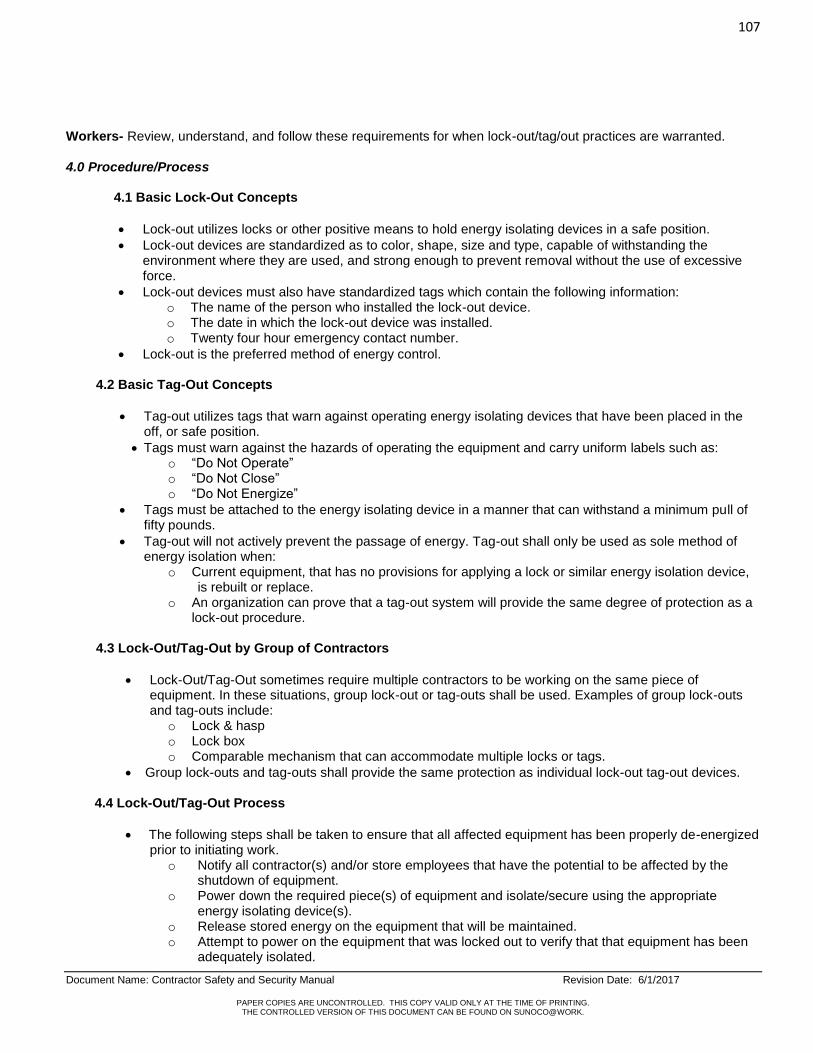
107
Document Name: Contractor Safety and Security Manual Revision Date: 6/1/2017
PAPER COPIES ARE UNCONTROLLED. THIS COPY VALID ONLY AT THE TIME OF PRINTING. THE CONTROLLED VERSION OF THIS DOCUMENT CAN BE FOUND ON SUNOCO@WORK.
Workers- Review, understand, and follow these requirements for when lock-out/tag/out practices are warranted. 4.0 Procedure/Process 4.1 Basic Lock-Out Concepts
Lock-out utilizes locks or other positive means to hold energy isolating devices in a safe position.
Lock-out devices are standardized as to color, shape, size and type, capable of withstanding the environment where they are used, and strong enough to prevent removal without the use of excessive force.
Lock-out devices must also have standardized tags which contain the following information: o The name of the person who installed the lock-out device. o The date in which the lock-out device was installed. o Twenty four hour emergency contact number.
Lock-out is the preferred method of energy control.
4.2 Basic Tag-Out Concepts
Tag-out utilizes tags that warn against operating energy isolating devices that have been placed in the off, or safe position.
Tags must warn against the hazards of operating the equipment and carry uniform labels such as: o “Do Not Operate” o “Do Not Close” o “Do Not Energize”
Tags must be attached to the energy isolating device in a manner that can withstand a minimum pull of fifty pounds.
Tag-out will not actively prevent the passage of energy. Tag-out shall only be used as sole method of energy isolation when:
o Current equipment, that has no provisions for applying a lock or similar energy isolation device, is rebuilt or replace.
o An organization can prove that a tag-out system will provide the same degree of protection as a lock-out procedure.
4.3 Lock-Out/Tag-Out by Group of Contractors
Lock-Out/Tag-Out sometimes require multiple contractors to be working on the same piece of equipment. In these situations, group lock-out or tag-outs shall be used. Examples of group lock-outs and tag-outs include:
o Lock & hasp o Lock box o Comparable mechanism that can accommodate multiple locks or tags.
Group lock-outs and tag-outs shall provide the same protection as individual lock-out tag-out devices.
4.4 Lock-Out/Tag-Out Process
The following steps shall be taken to ensure that all affected equipment has been properly de-energized prior to initiating work.
o Notify all contractor(s) and/or store employees that have the potential to be affected by the shutdown of equipment.
o Power down the required piece(s) of equipment and isolate/secure using the appropriate energy isolating device(s).
o Release stored energy on the equipment that will be maintained. o Attempt to power on the equipment that was locked out to verify that that equipment has been
adequately isolated.

108
Document Name: Contractor Safety and Security Manual Revision Date: 6/1/2017
PAPER COPIES ARE UNCONTROLLED. THIS COPY VALID ONLY AT THE TIME OF PRINTING. THE CONTROLLED VERSION OF THIS DOCUMENT CAN BE FOUND ON SUNOCO@WORK.
o Perform the work task which the equipment was isolated for. o Remove the energy isolating device(s) from the equipment that is being maintained. o Verify that the maintained equipment is running correctly after work task has been completed. o Notify all contractor(s) and/or store employees that were affected by the lock-out tag-out
process that the equipment has been fully restored and operational.
5.0 Key Documents/Tools/Reference Appendix A – Lockout /Tagout Inspection Form 29 CFR 1910.147 – The Control of Hazardous Energy (lock-out/tag-out). 29 CFR 1926.417 – Locking and Tagging of Circuits.
REVISION LOG
Revision Date Document Author
Document Authorizer Revision Details
5/10/2017 B. Drager J. Roberts Reformatting to new safety procedure format. Consolidation and reorganizing of prior Contractor Safety and Security Manual.

109
Document Name: Contractor Safety and Security Manual Revision Date: 6/1/2017
PAPER COPIES ARE UNCONTROLLED. THIS COPY VALID ONLY AT THE TIME OF PRINTING. THE CONTROLLED VERSION OF THIS DOCUMENT CAN BE FOUND ON SUNOCO@WORK.
Appendix A- Sample Form
Lock-Out Tag-Out Inspection Form
JOB TASK YES NO COMMENTS PRIOR TO WORK TASK TAKING PLACE
All affected contractors and employees been notified prior to initiating the Lock-Out/Tag-Out Process.
☐
☐
All required pieces of equipment been powered down using the appropriate energy isolating device(s).
☐
☐
All stored energy been released on the equipment that is being maintained.
☐
☐
Authorized employee attempted to start the process prior to maintaining the equipment?
☐
☐
DURING THE WORK TASK TAKING PLACE
All work while maintaining the equipment completed in a safe manner.
☐
☐
AFTER THE WORK HAS TAKEN PLACE
All energy isolation devices been removed?
☐
☐
Maintained equipment been verified to ensure that is operating correctly?
☐
☐
Affected contractors(s) and/or store employees that were affected by the lock-out tag-out process notified that the equipment has been fully restores and operational ?
☐
☐
SIGNATURE:___________________________________ DATE:__________

110
Document Name: Contractor Safety and Security Manual Revision Date: 6/1/2017
PAPER COPIES ARE UNCONTROLLED. THIS COPY VALID ONLY AT THE TIME OF PRINTING. THE CONTROLLED VERSION OF THIS DOCUMENT CAN BE FOUND ON SUNOCO@WORK.
Document Name: Contractor Safety & Security Manual Personal Protective Equipment Program
Document Number: HS-PRO-48
Issuing Dept: Health and Safety Department
Next Review Date: June 1, 2022
1.0 Purpose/Scope
This section describes contractor requirements and expectations when determining the type And usage of Personnel protective equipment. The scope of this procedure applies to all technical service contractors providing construction and maintenance services at Sunoco, LP Retail locations.
2.0 Definitions None 3.0 Responsibility Sunoco Representative is responsible for management of this document and its implementation. Effected Contractors are responsible for the knowledge of, and adherence to this program and ensuring all
of its employees use PPE when required. 4.0 Procedure/Process
4.1 HAZARD ASSESSMENT
Prior to commencing any construction work an assessment of the work to be done will be completed
by utilizing a job safety analysis to determine if hazards are present, or likely to be present, which
necessitate the use of personal protective equipment (PPE). Where hazards are present, or likely to
be present:
o Select, and have each affected employee use, the types of PPE that will protect the employee from the hazards identified in the hazard assessment.
o Communicate equipment selection decisions to each affected employee. o Select PPE that properly fits each affected employee. o Train employees in the use and care of PPE.
When the work to be performed includes hazardous waste material handling, such as asbestos-related work or hazardous material identified by an environmental assessment, all Personal Protective Equipment must be evaluated by a certified contractor and all government regulations must be followed. Special equipment such as respirators or rescue equipment may be required. Specialized training on personal protective equipment may also be needed.
4.2 SELECTION OF PERSONAL PROTECTIVE EQUIPMENT (PPE)
Personal protective equipment (PPE) will be selected on the basis of the hazards to which the
workers' are exposed or potentially exposed. All selections will be made with input from managers
and workers.

111
Document Name: Contractor Safety and Security Manual Revision Date: 6/1/2017
PAPER COPIES ARE UNCONTROLLED. THIS COPY VALID ONLY AT THE TIME OF PRINTING. THE CONTROLLED VERSION OF THIS DOCUMENT CAN BE FOUND ON SUNOCO@WORK.
Personal protective equipment will meet the following standards:
o Safety vests: Must meet ANSI Z107.1999 “American National Standard Practice for Occupational Safety”. Safety vests should be Class 2-II.
o Eye & Face Protection devices: ANSI Z87.1-1989 "American National Standard Practice for Occupational and Educational Eye and Face Protection. Safety goggles must be impact and chemical resistant.
o Foot Protection: ANSI Z41. “American National Standards Institute for Safety shoes. Construction employees are required to wear appropriate footwear when working in areas where there is a danger of foot injuries due to falling and rolling objects piercing the sole and where any employee’s feet are exposed to electrical hazards. All footwear must meet the requirements of ANSI Z41.
For all employees performing electrical work, footwear shall be acceptable for work with potential electrical hazards.
o Head Protection devices: ANSI Z89.1-2003 "American National Standard for Personal Protection - Protective Headwear for Industrial Workers.” Hard hats should be Type 1 E & G.
o Hand Protection: No national standard available - selection will be based on task performed, conditions present, duration of use, and the hazards and potential hazards identified.
o Hearing Protection: In the event work requires the use of hearing protection, prior to any work commencing the contractor must insure all appropriate hearing conservation protocols are in place and the correct type of ear protection is used.
o Respiratory Protection: In the event work requires the use of respiratory protection, prior to any work commencing the contractor must insure all appropriate respiratory protection protocols are in place and the correct type of respirator is used.
4.3 TRAINING
Contractor shall supply appropriate training at a minimum to cover the following: o Why PPE is necessary o When PPE is necessary o What PPE is necessary and any alternative choices of equipment o How to properly use, adjust, and wear PPE o The proper care, maintenance, storage, usage, and disposal of PPE
4.4 CARE OF PERSONAL PROTECTIVE EQUIPMENT
PPE will be regularly cleaned, inspected and stored according to instructions given during the
training sessions or as directed by supervisors or managers. Defective or damaged PPE shall not
be used.
5.0 Key Documents/Tools/References
Safe Work Practices for Contractors Working at Retail Petroleum/Convenience Facilities; API 1646, First Edition, August, 2006 OSHA Standard 29 CFR 1910.132-138: Personal Protective Equipment PPE and Safety Equipment Requirements

112
Document Name: Contractor Safety and Security Manual Revision Date: 6/1/2017
PAPER COPIES ARE UNCONTROLLED. THIS COPY VALID ONLY AT THE TIME OF PRINTING. THE CONTROLLED VERSION OF THIS DOCUMENT CAN BE FOUND ON SUNOCO@WORK.
APPENDIX 1 - PPE AND SAFETY EQUIPMENT REQUIREMENTS
Personal Protective Equipment Construction Projects
Long Pants Always
Reflective Vests Always
Gloves Must be on person Impervious (ex- nitrile) for chemicals. Leather for material handling. Cut resistant gloves for sharp materials.
Hearing Protection Consult with Safety and Risk if needed.
Hard Hats Always
Safety Foot wear (ANZI Z41) Always
Fire Resistant Clothing When there is a high risk of flash fire
Eye protection/Face Protection Always-Safety glasses with side shields at a minimum. Goggles when using any chemical, weed whacking, scraping paint, changing hoses and nozzles. Face shield: when exposure to impact hazard such as flying objects and road debris, chemical splashes, or potentially infectious fluid.
Safety Box Cutters Always-approved box cutters only
First Aid Kit Always
Fire Extinguisher Always
Flashlights and batteries Always
Caution Tape Always
Orange Cones (36”) Always
REVISION LOG
Revision Date Document Author
Document Authorizer Revision Details
5/17/2017 L. Pontani J. Roberts Reformatting to new safety procedure format. Consolidation and reorganizing of prior Contractor Safety and Security Manual.
ELECTRICAL WORK
ONLY QUALIFIED EMPLOYEES CAN PERFORM ELECTRICAL WORK AND SHALL
WEAR THE APPROPRIATE TYPE OF PPE TO PROTECT FROM ELECTRIC SHOCK,
ELECTROCUTION, FIRES, AND EXPLOSIONS.
DEPENDING ON THE JOB TASK TO BE PERFORMED, PPE FOR ELECTRIC WORK
INCLUDES SAFETY GLASSES, FACE SHIELDS, HARD HATS, SAFETY SHOES,
INSULATING (RUBBER) GLOVES WITH LEATHER PROTECTORS, INSULATING
SLEEVES, AND FLAME-RESISTANT (FR) CLOTHING.

113
Document Name: Contractor Safety and Security Manual Revision Date: 6/1/2017
PAPER COPIES ARE UNCONTROLLED. THIS COPY VALID ONLY AT THE TIME OF PRINTING. THE CONTROLLED VERSION OF THIS DOCUMENT CAN BE FOUND ON SUNOCO@WORK.
Document Name: Contractor Safety & Security Manual Safety Meetings
Document Number: HS-PRO-49
Issuing Dept: Health and Safety
Next Review Date: June 1, 2022
1.0 Purpose/Scope This purpose of this procedure is explain the requirements for contractor companies to conduct safety meetings at Sunoco LP sites. The scope of this procedure applies to all technical service contractors providing construction and maintenance services at Sunoco, LP Retail locations.
. 2.0 Definitions Safety Meetings – This phrase “Safety Meeting” covers a workgroup’s discussion on topics of safety, health, environmental, fire safety, emergency response, etc. It is not limited to only “safety-related” discussions. Safety Meetings are also referred to as: Toolbox Talks, Tailgate Sessions, etc. 3.0 Key Responsibilities Sunoco Representative – Explain the HES requirements for contractor companies to conduct Safety Meetings on a regular and as needed basis. Contractor Supervision – Ensure all required Safety Meetings occur and are documented. Prepare for the Safety Meeting and make it an educational and interactive session with the contractor workers. Ensure that documentation is given to the Sunoco Representative at his/her direction. Contractor Workers – Attend and participate in Safety Meetings. 4.0 Procedure/Process
4.1 Safety Meetings provide individuals with “how-to” information that will help them perform their jobs safely and encourage cooperation in the area of safety, health, environmental, fire safety, and emergency response.
4.2 Engineering, Environmental Services, and Construction Safety Meetings include contractor on-site meetings.
The records from these meetings are part of the OSHA-required contractor safety records. 4.3 Explaining the purpose and benefits of safety policies, asking workers to share motivational ideas, and
encouraging employees to report unsafe conditions are the first steps in getting employees involved in the company’s effort to maintain a safe and healthful work environment.
4.4 Regular Safety Meetings are one of the most effective ways to motivate employees to think about workplace
safety and health. These Safety Meetings familiarize employees with many occupational injury and illness prevention techniques. Supervisors and Managers must always be available and prepared for any employee questions or concerns relating to safety, health, environmental, and fire issues.
4.5 Safety Meeting Frequency and Format
A Safety Meeting is held as part of the Pre-Construction meeting. Multiple meetings or follow-up meetings may be required to ensure employees on shift work, vacation, etc. have the opportunity to attend the Safety Meeting.
Safety meetings should be held for contractors, sub-contractors, and employees periodically throughout the job to ensure that all personnel receive the information required to complete their work safely.

114
Document Name: Contractor Safety and Security Manual Revision Date: 6/1/2017
PAPER COPIES ARE UNCONTROLLED. THIS COPY VALID ONLY AT THE TIME OF PRINTING. THE CONTROLLED VERSION OF THIS DOCUMENT CAN BE FOUND ON SUNOCO@WORK.
Various types of multi-media should be utilized, such as: videos, handouts, photos, pamphlets, flyers, tools, safety equipment, topic-related materials or examples.
Meeting topics should pertain to local, state and federal regulations, Sunoco-specific requirements, contractor-company specific requirements, home safety, current news, etc.
Time should be allocated during the meeting for any employee questions or concerns relating to safety, health, environmental, fire safety, and emergency response.
The following is the Onsite or Offsite Safety Meeting Frequency and Format by Sunoco or Contractors.
Off –Site Sunoco Safety
Meetings
On-Site Safety Meetings by Contractor or Sunoco
Informal – “Toolbox Talk”
Formal Safety Meeting
Meeting Frequency Annually or as needed During construction (can be daily, weekly, or as needed).Example: Review of daily JSAs.
Pre-construction (required), Weekly during work (required), and post-construction (as needed)
Attendees Sunoco employees, contractors, vendors, and partners. Multiple or follow-up meetings may be required to ensure all employees have the opportunity to attend.
Contractor Supervisor, contractors, sub-contractors, vendors. Construction or Retail Project Engineer (optional)
Contractor Supervisor, contractors, sub-contractors, vendors. Construction or Retail Project Engineer (optional)
Tools / Multi-Media Videos, handouts, Presentations, topic related materials, examples.
Safety Plan, HES procedures. Typically verbal examples.
Safety plan, topic-related materials, examples, prior safety audit results, Lessons Learned, Safety Flashes.
Leader Engineering Manager, Construction Manager, Maintenance Manager, Health and Safety Manager, Retail/Project Engineer.
Contractor Supervisor or the supervisors designate.
Contractor Supervisor, the supervisor’s designee, or Construction/Retail Engineer.
Documentation Sign-in Documentation coordinated by Meeting Leader.
Coordinated by Meeting Leader. Attendance records kept in project file (if possible).
Coordinated by Meeting Leader. Attendance records kept in project file. These are part of the OSHA required contractor safety records.

115
Document Name: Contractor Safety and Security Manual Revision Date: 6/1/2017
PAPER COPIES ARE UNCONTROLLED. THIS COPY VALID ONLY AT THE TIME OF PRINTING. THE CONTROLLED VERSION OF THIS DOCUMENT CAN BE FOUND ON SUNOCO@WORK.
4.6 Safety Meeting Attendance
4.6.1 All contractor employees must participate in safety meetings as required by their company policy and as required by Sunoco.
4.6.2 Meetings are required to be documented and include the following information:
Date
Topic(s),
Discussion Leader
Names of Attendees.
5.0 Key Documents/Tools/Reference Appendix A – Sample Attendance Form – Safety Meeting
REVISION LOG
Revision Date Document Author
Document Authorizer Revision Details
5/22/2017 T. Kocis & L. Pontani
J. Roberts Reformatting to new safety procedure format. Consolidation and reorganizing of prior Contractor Safety and Security Manual.
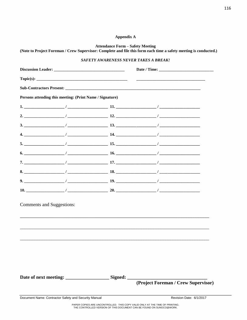
116
Document Name: Contractor Safety and Security Manual Revision Date: 6/1/2017
PAPER COPIES ARE UNCONTROLLED. THIS COPY VALID ONLY AT THE TIME OF PRINTING. THE CONTROLLED VERSION OF THIS DOCUMENT CAN BE FOUND ON SUNOCO@WORK.
Appendix A
Attendance Form – Safety Meeting
(Note to Project Foreman / Crew Supervisor: Complete and file this form each time a safety meeting is conducted.)
SAFETY AWARENESS NEVER TAKES A BREAK!
Discussion Leader: ___________________________________ Date / Time: ___________________________
Topic(s): _____________________________________________ __________________________________
Sub-Contractors Present: ___________________________________________________________________
Persons attending this meeting: (Print Name / Signature)
1. ____________________ / ____________________ 11. ____________________ / ____________________
2. ____________________ / ____________________ 12. ____________________ / ____________________
3. ____________________ / ____________________ 13. ____________________ / ____________________
4. ____________________ / ____________________ 14. ____________________ / ____________________
5. ____________________ / ____________________ 15. ____________________ / ____________________
6. ____________________ / ____________________ 16. ____________________ / ____________________
7. ____________________ / ____________________ 17. ____________________ / ____________________
8. ____________________ / ____________________ 18. ____________________ / ____________________
9. ____________________ / ____________________ 19. ____________________ / ____________________
10. ___________________ / ____________________ 20. ____________________ / ____________________
Comments and Suggestions:
______________________________________________________________________________
______________________________________________________________________________
______________________________________________________________________________
Date of next meeting: __________________ Signed: _________________________________
(Project Foreman / Crew Supervisor)

117
Document Name: Contractor Safety and Security Manual Revision Date: 6/1/2017
PAPER COPIES ARE UNCONTROLLED. THIS COPY VALID ONLY AT THE TIME OF PRINTING. THE CONTROLLED VERSION OF THIS DOCUMENT CAN BE FOUND ON SUNOCO@WORK.
Document Name: Contractor Safety & Security Manual Scaffolds
Document Number: HS-PRO-50
Issuing Dept: Health and Safety
Next Review Date: June 1, 2022
1.0 Purpose/Scope
The purpose of this procedure is to set the requirements for proper building, use, and removal of scaffolds. The scope of this procedure applies to all technical service contractors providing construction and maintenance services at Sunoco, LP Retail locations.
2.0 Definitions
Scaffold- Any temporary elevated platform, supported or suspended, and it supporting structures, including points of anchorage, used for supporting employees or materials or both.
Competent Person -One who is capable of identifying existing and predictable hazards in the surroundings or
working conditions which are hazardous or dangerous to employees, and who has the authority to take prompt corrective measures to eliminate them? The Competent Person must be knowledgeable about the requirements of this standard and have sufficient training or knowledge to identify and correct hazards encountered in scaffold work. A Competent Person must be properly trained.
Guardrail System - A vertical barrier, consisting of, but not limited to, top rails, midrails, and posts, erected to
prevent employees from falling off a scaffold platform or walkway to lower levels. Qualified Person - One who, by possession of a recognized degree, certificate, or professional standing, or who
by extensive knowledge, training, and experience, has successfully demonstrated his/her ability to solve or resolve problems related to the subject matter, the work, or the project.
3.0 Key Responsibilities
Sunoco Representative – Ensure that this procedure is communicated to the contractors.
Contractor Supervision – Ensure that this procedure is reviewed and followed by all personnel working on site, including the safe design and construction, inspection, use, and dismantling of scaffolds. Workers – Review, understand, and follow these requirements for building, inspecting, using, and dismantling scaffolds.
4.0 Procedure/Process
4.1 Design and Construction
Scaffolds must be of standard approved construction, and must be erected to meet local, state and federal codes.
Scaffolds must be erected by qualified personnel under the guidance of a competent person.
Poles, legs, posts, frames, and uprights must bear on base plates and mud sills or another firm foundation.
Scaffold uprights must be plum and square with cross-bracing on the front and back.
Leveling screws/Screw Jacks should not extend more than 18 in height.
Bases should be nailed to mudsill.
Planks should be ANSI-approved and stamped.
Planks should be secured to the frame (nails/heavy gauge wire).
Gaps between planking should not exceed more than 1 in.
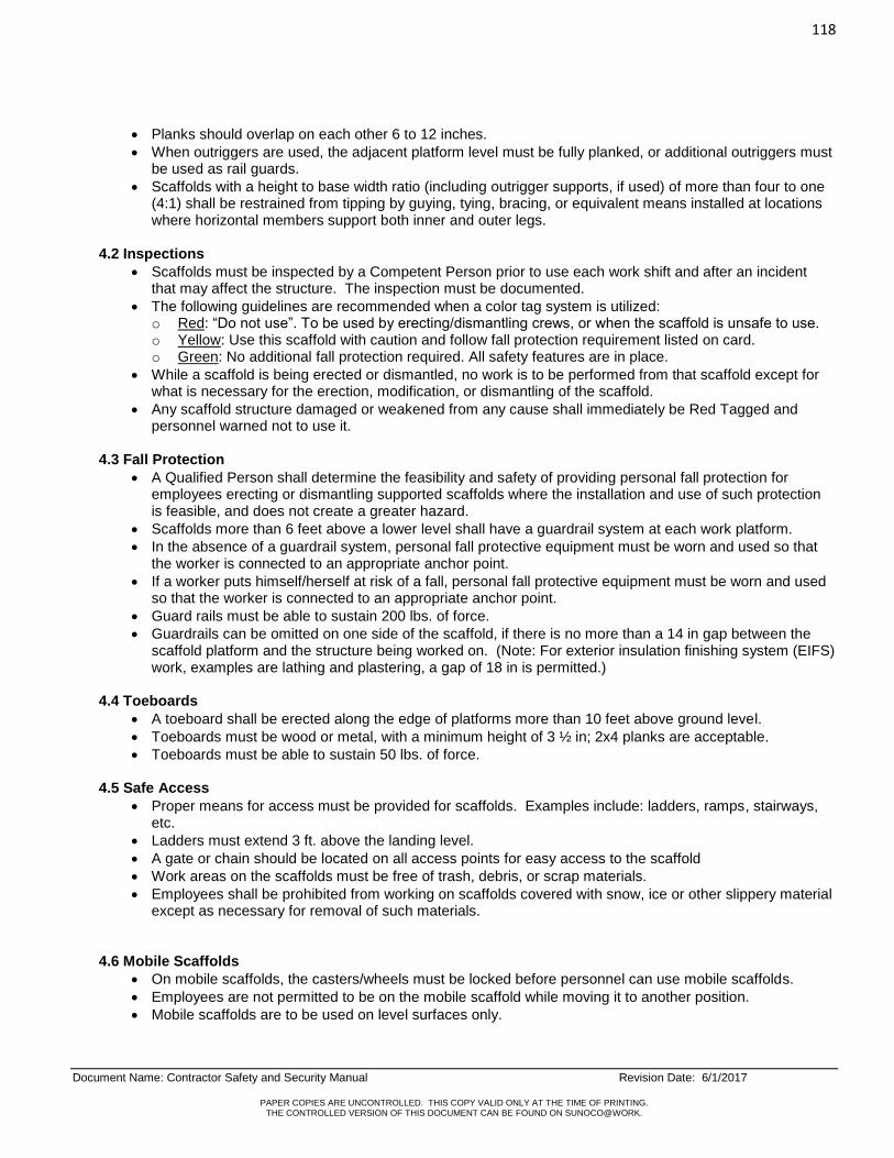
118
Document Name: Contractor Safety and Security Manual Revision Date: 6/1/2017
PAPER COPIES ARE UNCONTROLLED. THIS COPY VALID ONLY AT THE TIME OF PRINTING. THE CONTROLLED VERSION OF THIS DOCUMENT CAN BE FOUND ON SUNOCO@WORK.
Planks should overlap on each other 6 to 12 inches.
When outriggers are used, the adjacent platform level must be fully planked, or additional outriggers must be used as rail guards.
Scaffolds with a height to base width ratio (including outrigger supports, if used) of more than four to one (4:1) shall be restrained from tipping by guying, tying, bracing, or equivalent means installed at locations where horizontal members support both inner and outer legs.
4.2 Inspections
Scaffolds must be inspected by a Competent Person prior to use each work shift and after an incident that may affect the structure. The inspection must be documented.
The following guidelines are recommended when a color tag system is utilized: o Red: “Do not use”. To be used by erecting/dismantling crews, or when the scaffold is unsafe to use. o Yellow: Use this scaffold with caution and follow fall protection requirement listed on card. o Green: No additional fall protection required. All safety features are in place.
While a scaffold is being erected or dismantled, no work is to be performed from that scaffold except for what is necessary for the erection, modification, or dismantling of the scaffold.
Any scaffold structure damaged or weakened from any cause shall immediately be Red Tagged and personnel warned not to use it.
4.3 Fall Protection
A Qualified Person shall determine the feasibility and safety of providing personal fall protection for employees erecting or dismantling supported scaffolds where the installation and use of such protection is feasible, and does not create a greater hazard.
Scaffolds more than 6 feet above a lower level shall have a guardrail system at each work platform.
In the absence of a guardrail system, personal fall protective equipment must be worn and used so that the worker is connected to an appropriate anchor point.
If a worker puts himself/herself at risk of a fall, personal fall protective equipment must be worn and used so that the worker is connected to an appropriate anchor point.
Guard rails must be able to sustain 200 lbs. of force.
Guardrails can be omitted on one side of the scaffold, if there is no more than a 14 in gap between the scaffold platform and the structure being worked on. (Note: For exterior insulation finishing system (EIFS) work, examples are lathing and plastering, a gap of 18 in is permitted.)
4.4 Toeboards
A toeboard shall be erected along the edge of platforms more than 10 feet above ground level.
Toeboards must be wood or metal, with a minimum height of 3 ½ in; 2x4 planks are acceptable.
Toeboards must be able to sustain 50 lbs. of force. 4.5 Safe Access
Proper means for access must be provided for scaffolds. Examples include: ladders, ramps, stairways, etc.
Ladders must extend 3 ft. above the landing level.
A gate or chain should be located on all access points for easy access to the scaffold
Work areas on the scaffolds must be free of trash, debris, or scrap materials.
Employees shall be prohibited from working on scaffolds covered with snow, ice or other slippery material except as necessary for removal of such materials.
4.6 Mobile Scaffolds
On mobile scaffolds, the casters/wheels must be locked before personnel can use mobile scaffolds.
Employees are not permitted to be on the mobile scaffold while moving it to another position.
Mobile scaffolds are to be used on level surfaces only.

119
Document Name: Contractor Safety and Security Manual Revision Date: 6/1/2017
PAPER COPIES ARE UNCONTROLLED. THIS COPY VALID ONLY AT THE TIME OF PRINTING. THE CONTROLLED VERSION OF THIS DOCUMENT CAN BE FOUND ON SUNOCO@WORK.
4.7 Elevated Power Lines
The minimum clearance between scaffolds and power lines shall be 10 feet.
Scaffolds shall not be erected, used, dismantled, altered or moved so that a 10 feet clearance is maintained.
If there is a need to be within this 10 feet safe zone, a means of protecting the workers and power lines must be used.
5.0 Key Documents/Tools/Reference OSHA Standard 29 CFR 1926 Subpart L – Scaffolds OSHA Standard 29 CFR 1926 Subpart M – Fall Protection
REVISION LOG
Revision Date Document Author
Document Authorizer Revision Details
5/2/2017 T. Kocis J. Roberts Reformatting to new safety procedure format. Consolidation and reorganizing of prior Contractor Safety and Security Manual.

120
Document Name: Contractor Safety and Security Manual Revision Date: 6/1/2017
PAPER COPIES ARE UNCONTROLLED. THIS COPY VALID ONLY AT THE TIME OF PRINTING. THE CONTROLLED VERSION OF THIS DOCUMENT CAN BE FOUND ON SUNOCO@WORK.
Document Name: Contractor Safety & Security Manual Security Requirements
Document Number: HS-PRO-51
Issuing Dept: Health, Safety and Security Departments
Next Review Date: June 1, 2022
1.0 Purpose/Scope
This purpose of this procedure is explain the requirements for protection of assets, whether they be human, physical, financial, or information from criminal acts committed against the company or its contractors or customers at at Sunoco LP sites. The scope of this procedure applies to all technical service contractors providing construction and maintenance services at Sunoco, LP Retail locations.
2.0 Definitions
None 3.0 Key Responsibilities
Sunoco Representative – Set and explain to the Contractor Supervision the requirements for establishing, maintaining, and supporting sound Security measures and actions at Sunoco sites. Also, set the requirements for Security incident reporting, follow up on incidents, ensure an appropriate level of investigation is completed, and ensure documentation is provided and recorded (when necessary).
Contractor Supervision – Establish and maintain sound Security measures and actions when working at a Sunoco site. Support Sunoco Security measures when working at a Sunoco site. Ensure all Security incidents are properly reported to the Sunoco Representative, provide updated information on incidents, ensure an appropriate level of investigation is completed, and ensure documentation is provided to the Sunoco representative (when necessary).
Contractor Workers – Report all incidents to your supervisor.
4.0 Procedure/Process
4.1 Safe and Secure Work Environment - Contractors and their employees, vendors and sub-contractors are responsible for making their work environment secure by using sound judgment and principles. Contractors who need advice on a security problem should contact their local owner’s representative.
4.2 Contractors are expected to perform their duties in the best interest of Sunoco and their company and not
conduct any activity that is deemed unlawful by local, state, federal statues, or in violation of company policies.
4.3 Sunoco recognizes that criminal acts against Sunoco can result in substantial direct and indirect losses. In
addition, Sunoco employees’, contractors’ and customers’ well-being may be seriously jeopardized by these actions. As a result, the company intends to:
Secure all assets (human, physical, financial and information) in a prudent manner.
Investigate criminal acts against the company and identify the perpetrators.
Take appropriate action against perpetrators as determined by the nature of the offense. 4.4 It is the policy of Sunoco to maintain an environment for its employees and assets which provide for their
protection by minimizing potential harm or loss from criminal activity, abuse and policy violations. 4.5 No Firearms/Weapons Policy - Sunoco prohibits firearms of any type, or other weapons (as defined by
local statues, including, but limited to, handguns, rifles, shotguns, etc.) in or on any Company facility,

121
Document Name: Contractor Safety and Security Manual Revision Date: 6/1/2017
PAPER COPIES ARE UNCONTROLLED. THIS COPY VALID ONLY AT THE TIME OF PRINTING. THE CONTROLLED VERSION OF THIS DOCUMENT CAN BE FOUND ON SUNOCO@WORK.
company vehicle, or private vehicle on a Company facility. Violation of this policy may result in disciplinary action, and it could lead to a serious injury of an employee, customer, vendor, contractor, or visitor. Possessing a local, state, or federal permit for a firearm does not alter the No Firearms/Weapons Policy.
Exceptions: This policy does not apply to law enforcement personnel and armored car personnel who have official business on Company property and carry firearms as a routine part of their business.
4.6 Criminal Investigations - Sunoco requires contractors to provide information as needed to government
authorities and to Sunoco Security personnel to ensure a proper and professional investigation. Whenever criminal activity against the company or policy violations are discovered or suspected, the local Security Department or Corporate security shall be notified by phone.
4.7 Cooperation with Law Enforcement Authorities - Sunoco intends to cooperate with local, state, and
federal law enforcement authorities involved with investigating crimes committed against the company (including employees). Sunoco also expects contractors to cooperate fully with all law enforcement authorities as required.
Contractors should notify the local law enforcement authorities when circumstances dictate the need for immediate professional law enforcement services. Examples would be a violent crime, burglary, or robbery committed in a company facility.
4.8 Criminal Loss/Incident Reporting - All losses and threatened losses of company and personal assets must
be formally reported to the owner’s representative and the Sunoco Security Department. Examples of reportable losses or incidents (which are not all inclusive) are as follows:
Violent acts.
Theft (equipment, product, or funds).
Burglary.
Robbery.
Embezzlement.
Fraud/Waste/Abuse.
Threats (bombs, violence, obscene phone calls, mail).
Vandalism.
Conflicts of interest. 4.9 Equipment Security - It is the contractor’s responsibility to secure construction equipment and tools that are
to be left at a site during off-hours. Equipment should be removed by the contractor when equipment is not attended or in use.
5.0 Key Documents/Tools/Reference None
REVISION LOG
Revision Date Document Author
Document Authorizer Revision Details
4/7/2017 T. Kocis J. Roberts Reformatting to new safety procedure format. Consolidation and reorganizing of prior Contractor Safety and Security Manual.
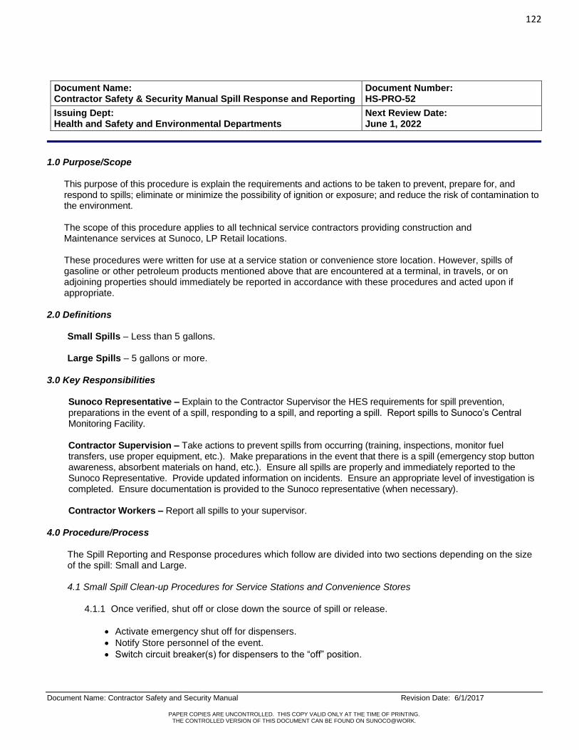
122
Document Name: Contractor Safety and Security Manual Revision Date: 6/1/2017
PAPER COPIES ARE UNCONTROLLED. THIS COPY VALID ONLY AT THE TIME OF PRINTING. THE CONTROLLED VERSION OF THIS DOCUMENT CAN BE FOUND ON SUNOCO@WORK.
Document Name: Contractor Safety & Security Manual Spill Response and Reporting
Document Number: HS-PRO-52
Issuing Dept: Health and Safety and Environmental Departments
Next Review Date: June 1, 2022
1.0 Purpose/Scope
This purpose of this procedure is explain the requirements and actions to be taken to prevent, prepare for, and respond to spills; eliminate or minimize the possibility of ignition or exposure; and reduce the risk of contamination to the environment. The scope of this procedure applies to all technical service contractors providing construction and Maintenance services at Sunoco, LP Retail locations. These procedures were written for use at a service station or convenience store location. However, spills of gasoline or other petroleum products mentioned above that are encountered at a terminal, in travels, or on adjoining properties should immediately be reported in accordance with these procedures and acted upon if appropriate.
2.0 Definitions
Small Spills – Less than 5 gallons. Large Spills – 5 gallons or more.
3.0 Key Responsibilities
Sunoco Representative – Explain to the Contractor Supervisor the HES requirements for spill prevention, preparations in the event of a spill, responding to a spill, and reporting a spill. Report spills to Sunoco’s Central Monitoring Facility. Contractor Supervision – Take actions to prevent spills from occurring (training, inspections, monitor fuel transfers, use proper equipment, etc.). Make preparations in the event that there is a spill (emergency stop button awareness, absorbent materials on hand, etc.). Ensure all spills are properly and immediately reported to the Sunoco Representative. Provide updated information on incidents. Ensure an appropriate level of investigation is completed. Ensure documentation is provided to the Sunoco representative (when necessary). Contractor Workers – Report all spills to your supervisor.
4.0 Procedure/Process
The Spill Reporting and Response procedures which follow are divided into two sections depending on the size of the spill: Small and Large.
4.1 Small Spill Clean-up Procedures for Service Stations and Convenience Stores
4.1.1 Once verified, shut off or close down the source of spill or release.
Activate emergency shut off for dispensers.
Notify Store personnel of the event.
Switch circuit breaker(s) for dispensers to the “off” position.
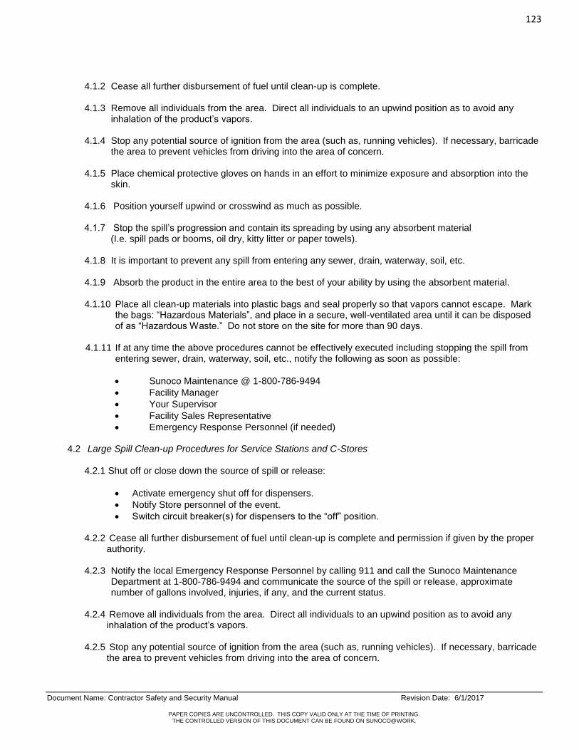
123
Document Name: Contractor Safety and Security Manual Revision Date: 6/1/2017
PAPER COPIES ARE UNCONTROLLED. THIS COPY VALID ONLY AT THE TIME OF PRINTING. THE CONTROLLED VERSION OF THIS DOCUMENT CAN BE FOUND ON SUNOCO@WORK.
4.1.2 Cease all further disbursement of fuel until clean-up is complete. 4.1.3 Remove all individuals from the area. Direct all individuals to an upwind position as to avoid any
inhalation of the product’s vapors. 4.1.4 Stop any potential source of ignition from the area (such as, running vehicles). If necessary, barricade
the area to prevent vehicles from driving into the area of concern. 4.1.5 Place chemical protective gloves on hands in an effort to minimize exposure and absorption into the
skin. 4.1.6 Position yourself upwind or crosswind as much as possible. 4.1.7 Stop the spill’s progression and contain its spreading by using any absorbent material (I.e. spill pads or booms, oil dry, kitty litter or paper towels). 4.1.8 It is important to prevent any spill from entering any sewer, drain, waterway, soil, etc. 4.1.9 Absorb the product in the entire area to the best of your ability by using the absorbent material. 4.1.10 Place all clean-up materials into plastic bags and seal properly so that vapors cannot escape. Mark
the bags: “Hazardous Materials”, and place in a secure, well-ventilated area until it can be disposed of as “Hazardous Waste.” Do not store on the site for more than 90 days.
4.1.11 If at any time the above procedures cannot be effectively executed including stopping the spill from
entering sewer, drain, waterway, soil, etc., notify the following as soon as possible:
Sunoco Maintenance @ 1-800-786-9494
Facility Manager
Your Supervisor
Facility Sales Representative
Emergency Response Personnel (if needed) 4.2 Large Spill Clean-up Procedures for Service Stations and C-Stores
4.2.1 Shut off or close down the source of spill or release:
Activate emergency shut off for dispensers.
Notify Store personnel of the event.
Switch circuit breaker(s) for dispensers to the “off” position.
4.2.2 Cease all further disbursement of fuel until clean-up is complete and permission if given by the proper authority.
4.2.3 Notify the local Emergency Response Personnel by calling 911 and call the Sunoco Maintenance
Department at 1-800-786-9494 and communicate the source of the spill or release, approximate number of gallons involved, injuries, if any, and the current status.
4.2.4 Remove all individuals from the area. Direct all individuals to an upwind position as to avoid any
inhalation of the product’s vapors. 4.2.5 Stop any potential source of ignition from the area (such as, running vehicles). If necessary, barricade
the area to prevent vehicles from driving into the area of concern.
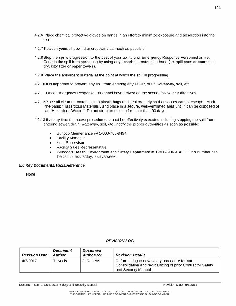
124
Document Name: Contractor Safety and Security Manual Revision Date: 6/1/2017
PAPER COPIES ARE UNCONTROLLED. THIS COPY VALID ONLY AT THE TIME OF PRINTING. THE CONTROLLED VERSION OF THIS DOCUMENT CAN BE FOUND ON SUNOCO@WORK.
4.2.6 Place chemical protective gloves on hands in an effort to minimize exposure and absorption into the skin.
4.2.7 Position yourself upwind or crosswind as much as possible. 4.2.8 Stop the spill’s progression to the best of your ability until Emergency Response Personnel arrive.
Contain the spill from spreading by using any absorbent material at hand (i.e. spill pads or booms, oil dry, kitty litter or paper towels).
4.2.9 Place the absorbent material at the point at which the spill is progressing. 4.2.10 it is important to prevent any spill from entering any sewer, drain, waterway, soil, etc. 4.2.11 Once Emergency Response Personnel have arrived on the scene, follow their directives. 4.2.12 Place all clean-up materials into plastic bags and seal properly so that vapors cannot escape. Mark
the bags: “Hazardous Materials”, and place in a secure, well-ventilated area until it can be disposed of as “Hazardous Waste.” Do not store on the site for more than 90 days.
4.2.13 if at any time the above procedures cannot be effectively executed including stopping the spill from
entering sewer, drain, waterway, soil, etc., notify the proper authorities as soon as possible:
Sunoco Maintenance @ 1-800-786-9494
Facility Manager
Your Supervisor
Facility Sales Representative
Sunoco’s Health, Environment and Safety Department at 1-800-SUN-CALL. This number can be call 24 hours/day, 7 days/week.
5.0 Key Documents/Tools/Reference
None
REVISION LOG
Revision Date Document Author
Document Authorizer Revision Details
4/7/2017 T. Kocis J. Roberts Reformatting to new safety procedure format. Consolidation and reorganizing of prior Contractor Safety and Security Manual.

125
Document Name: Contractor Safety and Security Manual Revision Date: 6/1/2017
PAPER COPIES ARE UNCONTROLLED. THIS COPY VALID ONLY AT THE TIME OF PRINTING. THE CONTROLLED VERSION OF THIS DOCUMENT CAN BE FOUND ON SUNOCO@WORK.
Document Name: Contractor Safety and Security Manual Tank Removal
Document Number: HS-PRO-053
Issuing Dept: Environmental, Health and Safety
Next Review Date: June 1, 2022
1.0 Purpose/Scope
The purpose of this procedure provides the guidelines for removal of underground storage tanks and piping. UST’s are removed by contractors hired by the Retail Engineering and Construction Department OR Maintenance Managers (waste & heating oil tanks only) with the involvement of Environmental Services to complete closure assessment reports and collect removal documents and update Sunoco’s facility database. The scope of this policy applies to all technical service contractors providing construction and maintenance services at Sunoco LP Retail locations.
2.0 Definitions
None
3.0 Key Responsibilities
Sunoco Representative – Ensure that this procedure is communicated to the contractors.
Contractor Supervision – Ensure that this procedure is reviewed and followed by all personnel working on site. Drivers/Workers – Review, understand, and follow these requirements when removing underground storage tanks and piping.
4.0 Procedure/Process
4.1 The following Tank Removal procedures and associated forms are intended as a general guide:
Tank Pull Notification: Retail Engineering and Construction Project Manager must send a 30 Day Notification Letter to Performance & Compliance Department at Ellis Preserve, Newtown Square, PA office. Performance & Compliance Department will notify the state and/or local regulatory agency. Instructions to Bidder: This letter includes the scope of work for the tank pull, Duns number, address, tank information, etc. Normally give a contractor two weeks maximum to respond with a bid. Bids will be reviewed by Sunoco Procurement personnel for awarding contract to contractor. Environmental Company Bid Request: This letter draft includes the scope of work for the Environmental Consultant. It includes duns number, address, tank information, etc. Allow a maximum of two weeks for a response time. General Contractor Acceptance Letter: This letter is sent to the contractor awarding him the contract for his signature, a blank Bill of Sale form and any other required Performance & Compliance Facility Data Sheets.
4.2 Removal Contractor required to send Bill of Sale to Construction OR Maintenance Project manager for
review and signature. Construction or Maintenance Project Manager must sign Bill of Sale (as Sunoco Representative) then forward to Compliance Services Department in Ellis Preserve for records retention. Construction or Maintenance Project Manager must then approve and process invoices submitted by removal contractor via Sunoco’s Maximo system (i.e. .PO’s) for payment to removal contractor.
.

126
Document Name: Contractor Safety and Security Manual Revision Date: 6/1/2017
PAPER COPIES ARE UNCONTROLLED. THIS COPY VALID ONLY AT THE TIME OF PRINTING. THE CONTROLLED VERSION OF THIS DOCUMENT CAN BE FOUND ON SUNOCO@WORK.
APPENDIX A TANK REMOVAL NOTIFICATION (EXAMPLE)

127
Document Name: Contractor Safety and Security Manual Revision Date: 6/1/2017
PAPER COPIES ARE UNCONTROLLED. THIS COPY VALID ONLY AT THE TIME OF PRINTING. THE CONTROLLED VERSION OF THIS DOCUMENT CAN BE FOUND ON SUNOCO@WORK.

128
Document Name: Contractor Safety and Security Manual Revision Date: 6/1/2017
PAPER COPIES ARE UNCONTROLLED. THIS COPY VALID ONLY AT THE TIME OF PRINTING. THE CONTROLLED VERSION OF THIS DOCUMENT CAN BE FOUND ON SUNOCO@WORK.

129
Document Name: Contractor Safety and Security Manual Revision Date: 6/1/2017
PAPER COPIES ARE UNCONTROLLED. THIS COPY VALID ONLY AT THE TIME OF PRINTING. THE CONTROLLED VERSION OF THIS DOCUMENT CAN BE FOUND ON SUNOCO@WORK.
APPENDIX B - INSTRUCTIONS TO BIDDERS (EXAMPLE)

130
Document Name: Contractor Safety and Security Manual Revision Date: 6/1/2017
PAPER COPIES ARE UNCONTROLLED. THIS COPY VALID ONLY AT THE TIME OF PRINTING. THE CONTROLLED VERSION OF THIS DOCUMENT CAN BE FOUND ON SUNOCO@WORK.

131
Document Name: Contractor Safety and Security Manual Revision Date: 6/1/2017
PAPER COPIES ARE UNCONTROLLED. THIS COPY VALID ONLY AT THE TIME OF PRINTING. THE CONTROLLED VERSION OF THIS DOCUMENT CAN BE FOUND ON SUNOCO@WORK.

132
Document Name: Contractor Safety and Security Manual Revision Date: 6/1/2017
PAPER COPIES ARE UNCONTROLLED. THIS COPY VALID ONLY AT THE TIME OF PRINTING. THE CONTROLLED VERSION OF THIS DOCUMENT CAN BE FOUND ON SUNOCO@WORK.
APPENDIX C – ENVIRONMENTAL CONSULTANT BID REQUEST (RFQ & INSTRUCTIONS)
Construction Project Manager will inquire via electronic email to Environmental engineer to inquire if site is a currently open (active) remediation site.
If site IS a currently open (active) remediation site, then the current environmental remediation consultant will be required to complete and submit a bid package electronically with quote for services to perform the underground storage tank closure site assessment and submittal to the required regulatory agencies. If Sunoco accepts quote, a Purchase Order will be issued electronically via Sunoco’s Maximo system.
If the site IS NOT an open (active) remediation site, the Construction Project Manager will send out bid requests (RFQ) Request for Quotation to multiple Environmental Consultants electronically via Sunoco’s Maximo system.
After all eligible RFQ’s are reviewed and an Environmental Consultant awarded, a Purchase Order will be issued electronically via Sunoco’s Maximo system to the Environmental Consultant to complete services to perform the underground storage tank closure site assessment and submittal to the required regulatory agencies.

133
Document Name: Contractor Safety and Security Manual Revision Date: 6/1/2017
PAPER COPIES ARE UNCONTROLLED. THIS COPY VALID ONLY AT THE TIME OF PRINTING. THE CONTROLLED VERSION OF THIS DOCUMENT CAN BE FOUND ON SUNOCO@WORK.
134
Document Name: Contractor Safety and Security Manual Revision Date: 6/1/2017
PAPER COPIES ARE UNCONTROLLED. THIS COPY VALID ONLY AT THE TIME OF PRINTING. THE CONTROLLED VERSION OF THIS DOCUMENT CAN BE FOUND ON SUNOCO@WORK.

135
Document Name: Contractor Safety and Security Manual Revision Date: 6/1/2017
PAPER COPIES ARE UNCONTROLLED. THIS COPY VALID ONLY AT THE TIME OF PRINTING. THE CONTROLLED VERSION OF THIS DOCUMENT CAN BE FOUND ON SUNOCO@WORK.
INSTRUCTIONS TO ENVIRONMENTAL CONSULTANT
During the course of any project, environmental impacts or issues may be encountered. The appropriate Sunoco Personnel are to be notified IMMEDIATELY if an issue or impact arises. The contractor is NOT to proceed with that specific portion of the project until given the appropriate approvals from Sunoco or their authorized representative.
For many projects, a Sunoco Environmental Consultant (SEC) will be assigned. The SEC will be responsible for Coordinating the following (if needed):
Water Treatment System(s)
Frac Tanks - Delivery, treatment and discharge of water, cleaning and removal.
Obtaining the appropriate samples under each dispenser, UST or product piping.
This is to be coordinated between GC and SEC.
Any necessary trucking and disposal of any contaminated soils.
If any excavated materials show signs of contamination, they are to be “staged” on-site until they can be disposed of properly.
GC will be responsible for removal of all rock, concrete and asphalt generated from construction from stockpiled dirt.
DO NOT stockpile rocks, concrete or asphalt with soils that are being taken to a Sunoco approved landfill. Failure to comply will result in back charges to the GC.
GC will be responsible for loading all soil generated once they are tested and ready to be removed from the site
At the time this document has been generated, it is anticipated that the GC will be responsible for the following:
Any and all costs related to removing and replacing excavated materials shall be part of the bid document spreadsheet.
This quantity of material is expected to be generated by the construction activities as outlined in this document and do not include any additional soils that may be removed under the direction of any Federal, State or Local agency.
Backfill the existing excavations with Sunoco approved backfill materials. No broken pavement or other large pieces shall be neither used, nor any organic materials.
Consult with the Sunoco Construction Engineer prior to any backfill activities. Sunoco Standards must be adhered to and 3rd Party Inspections may be required.
Include in their bid any and all costs related to dewatering excavations necessary to properly install structures, UST’s, foundations, etc. to complete this project.
Environmental Consultant TBD
STATE ID # XXXXXXX
EPA ID # (if available) XXXXXXX
Anticipated Soils – Remove & Replace (tons) XXXX
Anticipate to Dewater YES / NO

136
Document Name: Contractor Safety and Security Manual Revision Date: 6/1/2017
PAPER COPIES ARE UNCONTROLLED. THIS COPY VALID ONLY AT THE TIME OF PRINTING. THE CONTROLLED VERSION OF THIS DOCUMENT CAN BE FOUND ON SUNOCO@WORK.
APPENDIX D - UNDERGROUND STORAGE TANK REMOVAL (EXAMPLE) A. General Notes:
1. The Compliance Services Department will provide State and/or Local Regulatory agency a 30-day notification letter or form provided by regulatory agency within 30 days prior to the underground storage tank removal.
2. The Risk Management Department will provide a separate environmental consultant to oversee
environmental responsibilities to include and perform all site assessment activities. Contractor will be responsible for coordinating tank removal times with the environmental consultant and assist with sample collections.
3. Sunoco’s Central Scheduling Department, as directed by Construction or Maintenance Project Manager, is
responsible for removing product from underground product storage tanks prior to removal.
4. Contractor shall obtain all permits required by and schedule with all federal, state, and local agencies to perform and witness, if applicable the tank removal, disposal, and backfilling of underground tank systems.
5. Contractor responsible for adhering to all Health and Safety procedures of Sunoco LP.
6. Contractor will provide all manifests, bill of sale for tanks, acquired permits, UST certificate of disposal, and all
correspondence within (15) fifteen working days of tank removal to Construction or Maintenance Project Manager. Note: Invoice must include a complete breakdown of work performed, extras must be approved in advance and submitted via Sunoco’s Maximo system.
7. Contractor to submit rates for material, labor and equipment for Out of Scope work.
8. Contractor responsible for all taxes on materials and labor where applicable.
9. Contractor to submit bids by 3:00 pm on date specified on Request for Quotation (RFQ).
10. Dealer responsible for removing fuel oil and waste oil from underground storage tanks prior to removal.
Sunoco Project Manager responsible to schedule fuel oil and waste oil pump out for Co-op sites.
11. All Manifests to be made out to: Sunoco LLC Auto Lab Building 100 Green Street Marcus Hook, PA 19061 Attn: Environmental Compliance
12. Contractor to provide photographs to document all critical stages of underground storage tank removal. 13. Contractor is awarded a project by sending a Purchase Order/Contract Release electronically via Sunoco’s
Maximo system. The contractor acknowledges receipt of the Purchase Order/Contract Release back to Sunoco electronically through the Maximo system.

137
Document Name: Contractor Safety and Security Manual Revision Date: 6/1/2017
PAPER COPIES ARE UNCONTROLLED. THIS COPY VALID ONLY AT THE TIME OF PRINTING. THE CONTROLLED VERSION OF THIS DOCUMENT CAN BE FOUND ON SUNOCO@WORK.
B. Bid Items
1. Remove and dispose of ________ gals, fiberglass, ______ gal, steel underground gasoline storage tanks and all related piping complete to islands, including conduit and vent piping.
2. Remove and dispose of _______ gals, fiberglass, ______ gals, steel underground waste oil and fuel tanks
and all related piping, including conduit and vent piping.
3. Remove and dispose of service station canopy, including all structural steel members and columns, decking material, conduit and wiring, and column foundations.
4. If applicable, remove and dispose of service station canopy, including all structural steel members and
columns, decking material, conduit and wiring, and column foundations. C. Scope of Work:
The contractor shall perform the following work: All demolition materials and scrap shall be disposed of in a legal manner and in accordance with all Local, State, Federal or other agencies having jurisdiction.
Remove existing concrete tank mats
Remove and set pea gravel aside on plastic to be reused as backfill.
If native soil is encountered and requires removal, stockpile on plastic and cover.
Soil to be tested and transported by others.
DO NOT stockpile rocks, concrete, or asphalt with soils that are being taken to an approved Sunoco landfill. Failure to comply will result in back charges to the GC.
Remove concrete island mat(s)
Remove existing product and vent lines
Tank removal:
Tanks are to be removed in their entirety prior to demolition of the same. There should not be any pieces of the tank/piping left in the excavations.
Disconnect and remove wiring from circuit panel for all items to be removed, including dispensers, submerged pumps, cathodic systems, lighting, signs, monitoring equipment, intercom, and any other electrical equipment.
Remove and transport off site for disposal the following tanks:
Prior to excavating tanks, blow back all product lines from dispensers to tanks.
Pull the check valves on suction systems; remove the submersible pump check valves on pressure systems.
Remove residual product tank bottoms from all tanks.
Excavate to the tops of all tanks to be removed.
Disconnect all piping from tanks and plug appropriately.
Excavate down side of first tank for removal. Lift tank partially out of excavation tipped to allow product/sludge to accumulate at end of tank for removal.
Insert pump out pipe connected to vacuum type equipment for residual product/sludge removal.
Introduce water through opening at high end of tank to residual sludge to end of tank for removal.
Water to be removed by vacuum type system only. No electric or gas operated pumps allowed.
Properly store, label, and dispose of any residuals from the tanks.
Upon determining gas and sludge has been removed, prepare tank for final removal.
Install a venturi system (Jetair Hornet Tuthill System), or equivalent, at opening on low end of tank.
The venturi is to be operated continuously with an air compressor capable of producing a minimum of 175 psi.

138
Document Name: Contractor Safety and Security Manual Revision Date: 6/1/2017
PAPER COPIES ARE UNCONTROLLED. THIS COPY VALID ONLY AT THE TIME OF PRINTING. THE CONTROLLED VERSION OF THIS DOCUMENT CAN BE FOUND ON SUNOCO@WORK.
At opposite end of tank introduce a minimum of 10 pounds of dry ice per 1000 gallon of tank capacity.
Dry ice is to be handled with leather palm gloves only.
Continue introducing air via the venturi system to reduce the concentrations of flammable vapors.
During removal, a combustible gas indicator (CGI) also known as an explosion meter is to be used to measure the reduction in the concentration of flammable vapors.
The meter is used to determine the lower explosion limit (LEL) of vapors present.
The goal when purging a tank for transportation is to reduce the LEL to “0” (zero) or as close to zero as possible, removing the vapors as well as the oxygen from inside tanks to prevent an explosion.
Once acceptable levels of concentrations have been attained, plug tank openings for final removal.
Allow tank to vent by using (2) 4” plugs with ¼” drilled holes. In the event a tank bung is damaged, it is permissible to drive a soft wood plug into the
opening.
Tanks are not to be transported unless openings are properly secured.
Cut up and dispose of tanks off site in accordance with all applicable EPA and State regulations.
Excavate soil a minimum of two (2) feet around all sides and under tanks.
Leave as much soil in ground as possible until contamination levels are determined (if any).
Soil is to be stock piled on plastic and covered with plastic until disposed of or used as back fill.
After the results of laboratory testing and the approval by Sunoco, the excavated hole is to be filled with approved backfill material.
No broken pavement or other large pieces shall be neither used, nor any organic materials.
Typical acceptable materials would be pit run gravel, crushed stone, slag, or sand.
Backfill placed in 8” layers and compacted per Sunoco specs.
Sunoco will provide State EPA and the State Fire Marshal a 30 day notification prior to the underground storage tank removal.
Sunoco is responsible for pumping out product from underground gasoline tanks prior to removal.
GC shall obtain all permits required by federal, state, and local agencies to perform tank removal, disposal, and back filling of underground tank systems

139
Document Name: Contractor Safety and Security Manual Revision Date: 6/1/2017
PAPER COPIES ARE UNCONTROLLED. THIS COPY VALID ONLY AT THE TIME OF PRINTING. THE CONTROLLED VERSION OF THIS DOCUMENT CAN BE FOUND ON SUNOCO@WORK.
APPENDIX E – BILL OF SALE FOR UNDERGROUND STORAGE TANKS (EXAMPLE)

140
Document Name: Contractor Safety and Security Manual Revision Date: 6/1/2017
PAPER COPIES ARE UNCONTROLLED. THIS COPY VALID ONLY AT THE TIME OF PRINTING. THE CONTROLLED VERSION OF THIS DOCUMENT CAN BE FOUND ON SUNOCO@WORK.
5.0 Key Documents/Tools/Reference Appendix A - Tank Removal Notification (Example) Appendix B - Instructions to Bidders (RFQ) Request of Bid Appendix C – Environmental Consultant Bid Request (RFQ) Request for Bid (Example) & Instructions Appendix D – Underground Storage Tank Removal Appendix E – Bill of Sale for Underground Storage Tanks (Example)
REVISION LOG
Revision Date Document Author
Document Authorizer Revision Details
6/1/17 H. Doherty J. Roberts Reformatting to new safety procedure format. Consolidation and reorganizing of prior Contractor Safety and Security Manual.