retailer / qualified installer installation & operating
TRANSCRIPT

Read these instructions carefully. These instructions MUST stay with this product.
USASERVICE OFFICEDometic Corporation1120 North Main StreetElkhart, IN 46514
CANADADometic Corporation46 Zatonski, Unit 3Brantford, ON N3T 5L8CANADA
SERVICE CENTER &DEALER LOCATIONSPlease Visit:www.eDometic.com
RECORD THIS INFORMATION FOR FUTURE REFERENCE:
Model NumberSerial NumberDate PurchasedRetailer / Qualified Installer
OASIS ELITE975 SERIES
AUTOMATIC RV DOOR AWNING SYSTEM
MODEL975XX48.XX0(#), 975XX48.XX0(#)L,975XX56.XX0(#), 975XX56.XX0(#)L,975XX60.XX0(#), 975XX60.XX0(#)L
INST
ALL
ATIO
N &
OPE
RAT
ING
INST
RU
CTI
ON
S
REVISION BForm No. 3310396.043 09/16(French 3310425.040_B)©2016 Dometic CorporationLaGrange, IN 46761

2
TABLE OF CONTENTSINTRODUCTION ....................................................................................................................................................................2DOCUMENT SYMBOLS ........................................................................................................................................................3IMPORTANT SAFETY INSTRUCTIONS ................................................................................................................................3
A. Recognize Safety Information ...................................................................................................................................3B. Understand Signal Words ..........................................................................................................................................3C. Supplemental Directives ............................................................................................................................................3D. General Safety Messages .........................................................................................................................................3
SPECIFICATIONS ..................................................................................................................................................................4A. Door Clearance .........................................................................................................................................................4B. Wire Length And Size ................................................................................................................................................4C. Awning Dimensions ...................................................................................................................................................4
GENERAL INFORMATION .....................................................................................................................................................5A. Included Hardware ....................................................................................................................................................5B. Additional Components & Kits ...................................................................................................................................5
PREPARE FOR INSTALLATION ............................................................................................................................................5A. Door Roller And Edge Guard (Optional) ....................................................................................................................5B. Prepare Awning Rail ..................................................................................................................................................5C. Determine Awning Location .......................................................................................................................................6
INSTALL ELECTRICAL KITS .................................................................................................................................................6A. Mount Electronic Control Box ....................................................................................................................................6B. Install Wiring To Awning Motor ..................................................................................................................................6C. Install (Fixed / Wired) Remote Awning Switch ...........................................................................................................7D. Install Ignition / Safety Interlock System ....................................................................................................................7E. Connect Electronic Control Box To Power Supply .....................................................................................................7F. Install LED Light Switch (If Applicable) ......................................................................................................................8
INSTALL AWNING ..................................................................................................................................................................8A. Install Awning Rail And Insert Awning ........................................................................................................................8B. Electrical Connections To Awning ..............................................................................................................................8C. Complete Installation .................................................................................................................................................9D. LED Light Connections (If Applicable) .....................................................................................................................10E. Secure Awning For Travel .......................................................................................................................................10
VERIFY INSTALLATION.......................................................................................................................................................10A. Test Operation .........................................................................................................................................................10B. Limit Switch Adjustment ...........................................................................................................................................10C. Secure Awning For Travel ....................................................................................................................................... 11D. Keep Literature ........................................................................................................................................................ 11
OPERATION ......................................................................................................................................................................... 11A. Open Awning ........................................................................................................................................................... 11B. Close Awning ........................................................................................................................................................... 11C. Prepare Awning For Travel ...................................................................................................................................... 11
CLOSE OR REMOVE AWNING (POWER FAILURE) ..........................................................................................................12A. Close Awning Manually .........................................................................................................................................12B. Remove Awning From RV .......................................................................................................................................13
INTRODUCTIONThese instructions apply to the Oasis Elite 975 series awnings (hereinafter referred to as “door awning”, “awning,” or “prod-uct”). It is designed for use over RV entry doors. This awning can be installed by one person with brief help from additional personnel. Use these instructions to ensure correct installation, function, and operation of product.Dometic Corporation reserves the right to modify appearances and specifications without notice.

GENERAL CARE AND USE .................................................................................................................................................13A. Precautions ..............................................................................................................................................................13B. Hardware Maintenance ...........................................................................................................................................13C. Fabric Maintenance .................................................................................................................................................13D. When To Get More Help ..........................................................................................................................................14
APPENDIX A: ELECTRONIC CONTROL KIT WIRING ........................................................................................................15
TABLE OF CONTENTS
3
IMPORTANT SAFETY INSTRUCTIONS
DOCUMENT SYMBOLSIndicates additional information that is NOT related to physical injury.
Indicates step-by-step instructions.
This manual has safety information and instructions to help you eliminate or reduce the risk of accidents and injuries.
A. Recognize Safety InformationThis is the safety alert symbol. It is used to alert you to potential physical injury hazards. Obey all safety messages that follow this symbol to avoid possible injury or death.
B. Understand Signal WordsA signal word will identify safety messages and property damage messages, and will indicate the degree or level of hazard seriousness.
indicates a hazardous situation that, if NOT avoided, could result in death or serious in-jury. indicates a hazardous situation that, if NOT avoided, could result in minor or moderate injury. is used to address practices NOT related to physical injury.
C. Supplemental DirectivesRead and follow all safety information and instructions to avoid possible injury or death.
Read and understand these instructions be-fore [installing / using / servicing / performing maintenance on] this product.
Incorrect [installation / operation / servicing / maintaining] of this product can lead to seri-ous injury. Follow all instructions.
The installation MUST comply with all ap-
plicable local and national codes, including the latest edition of the following standards:
U.S.A. ● ANSI/NFPA70, National Electrical Code
(NEC) ● ANSI/NFPA 1192, Recreational Vehicles
Code
CANADA ● CSA C22.1, Parts l & ll, Canadian Electri-
cal Code ● CSA Z240 RV Series, Recreational
Vehicles
D. General Safety Messages
Failure to obey the following warn-ings could result in death or serious injury:
● This product MUST be [installed / serviced] by a qualified service technician.
● Do NOT modify this product in any way. Modifica-tion can be extremely hazardous.
● Frequently examine product for imbalance (un-even fit / sagging / loose parts); and signs of wear or damage to wiring (if applicable) and other criti-cal parts. Do NOT use product if adjustments or repairs are necessary.
Critical parts may include awning fabric, cables, arm assemblies, etc.
● Disconnect product from power supply (if ap-plicable), and do NOT operate product when maintenance (such as window cleaning) is being carried out in the vicinity.
● Do NOT allow anyone (including children) with

4
A. Door ClearanceMaintain a minimum distance of 10 1/2” between awning rail and entry door. See (FIG. 1).
FIG. 1
Avoid Interference
RV Door (Open)
10 1/2″
Awning Rail
B. Wire Length And SizeTo avoid voltage drop, follow wire length guide for all awning wiring. See “Table 1” below.
Table 1 Wire Length Wire Size10’ & Under 14 Gauge
11’ to 30’ 12 GaugeOver 30’ 10 Gauge
C. Awning Dimensions1. Awning overall dimensions. See (FIG. 2).
FIG. 2A
C
B
Model A B C975XX48.XX0(#)(L) 48 1/2” 6” 4”975XX56.XX0(#)(L) 55 1/2” 6” 4”975XX60.XX0(#)(L) 59 1/2” 6” 4”
2. Awning wiring hole location. See (FIG. 3).
FIG. 3
11/16″
3 5/8″
Wiring Hole
Awning Back Rail
LH Cover
SPECIFICATIONS
IMPORTANT SAFETY INSTRUCTIONSreduced physical, sensory or mental capabilities, or lack of experience and knowledge to use this product, unless they have been given supervision or instruction (concerning use of this product) by a person responsible for their safety.
● Do NOT allow children to play with product or with fixed controls (if applicable).
● Keep remote controls (if applicable) away from children.
● IMPACT OR CRUSH HAZARD. NEVER leave an open awning unattended. Keep awning stowed (closed) when snow, heavy rain, wind, and severe weather conditions are expected.
● IMPACT OR CRUSH HAZARD. Do NOT allow
water to pool, snow to accumulate, or heavy debris on awning fabric. Do NOT hang or place anything on awning. The awning will become unstable, and could bend or collapse.
● FIRE HAZARD. Keep sources of heat and fire (barbecue grills, portable heater, etc.) away from awning. Failure to obey this warning could result in death or serious injury.
PINCH HAZARD. Maintain a hori-zontal distance of at least 16″ between fully open awning and any permanent object. Failure to obey this caution could result in injury.
Do NOT face awning toward permanent objects that may interfere with awning op-eration.

5
FIG. 5
Door Edge Guard
Inner Screen Door
B. Prepare Awning Rail
Make sure awning rail is parallel to RV floor, and is NOT warped or curved before in-stalling awning fabric. If awning rail is NOT straight, awning fabric may wrinkle or stretch.Select desired awning rail end (on RV) into which awning fabric will be inserted. Flare (widen) that end of rail with a flat-bladed screwdriver, and re-move (file) sharp edges. See (FIG. 6).
FIG. 6
Before After
PREPARE FOR INSTALLATIONA. Door Roller And Edge Guard (Optional)
Do NOT allow corner of entry door to contact awning fabric. Otherwise, premature wear or tearing of awning fabric could occur.If there is potential for a squared corner entry door to contact awning fabric, a door roller kit (NOT IN-CLUDED) must be installed.
Rounded corner doors may NOT require a door roller kit if there is no potential for dam-age to awning fabric.See subsection, “B. Additional Components & Kits” on page (5) to order door roller kits.
1. Install door roller. See (FIG. 4).a. Place door roller at upper corner (opposite
to hinge) of outer entry door. Face roller out, and 1/4” to 3/8” above door.
b. Place and tighten self-drilling screws (pro-vided) through mounting holes and into door.
FIG. 4
Position Wheel Directly Over Edge Of Door
Outer Entry Door
1/4″ - 3/8″(Above Door)
2. Clip door edge guard onto upper corner (oppo-site to hinge) of inner screen door. See (FIG. 5).
GENERAL INFORMATIONA. Included Hardware
(2) #10-16 X 5/8” Self-Drilling Screws(*) #6-20 X 1/2” Square Drive Screw
* Quantity varies by length of awning rail.
B. Additional Components & Kits(1) 830304 Door Roller Kit(1) 830304.003 Door Roller Kits (50 Pack) 3310287.010 Electronic Control KitAlthough this kit includes a wiring harness kit, ad-ditional wiring (installer supplied) is still required.
3310287.002 Electronic Control KitThis kit will require additional components and wir-ing (installer supplied):(4) 350766-1 Plug (3 Position)(4) 350777-1 Plug (2 Position)(1) 350779-1 Plug (4 Position)(6) 350689-1 Socket (18-24 gauge)(1) 350550-1 Socket (14-20 gauge)(2) 640310-1 Socket (10-12 gauge)(14) 350547-1 Pin (14-20 gauge)

6
C. Determine Awning Location
1. IMPACT OR CRUSH HAZARD. Make sure mounting surface on RV is flat, has solid structural backing where fasteners pene-trate surface, and will safely and securely sup-port product. Otherwise, product may become unstable and could [detach / bend / collapse]. Failure to obey this warning could result in death or serious injury.Find a solid structure in RV wall (centered over door) for support of awning rail and back rail (all mounting points).
PREPARE FOR INSTALLATION2. Allow for sufficient clearance be-
tween awning fabric and entry door to accom-modate awning pitch (slope).Avoid location that interferes with entry door swing when awning is completely extended. See subsection, “A. Door Clearance” on page (4).
3. Maintain a minimum of 1/2” clearance at top and sides of awning case.
Additional clearance is recommended to allow easier access for servicing.
INSTALL ELECTRICAL KITS ELECTRICAL SHOCK HAZARD. Disconnect 120 Vac power from RV. Failure to obey this warning could result in death or serious injury. Failure to obey the following notices could damage product or property.
● Disconnect the positive (+) 12 Vdc terminal from supply battery. Otherwise, damage to unit could occur.
● Do NOT pinch wiring or allow wiring to rub against sharp edges. If wiring is damaged, it MUST be replaced by a qualified service techni-cian.
Disconnect power for ALL procedures under this section.To complete electrical installation, an electronic control kit is required. See subsection, “B. Addi-tional Components & Kits” on page (5) to order.
The electronic control is pre-wired for Weath-erPro awning installation. If a WeatherPro awning is NOT installed, only the Oasis Elite door awning connections will be used.The electronic control and key fob are pro-grammed as a matched set. They MUST re-main together.
A. Mount Electronic Control Box1. Find a suitable location for electronic control box
that’s protected from weather and other adverse conditions.
Avoid mounting control box close to steel framing. Recommended mounting loca-tions include protected compartments outside living quarters (such as basement storage).
2. Place and tighten #6-20 X 1” screws (provided) through control kit base (mounting holes) and into mounting surface of RV.
B. Install Wiring To Awning MotorAn electronic control kit (NOT INCLUDED) MUST be used to perform this step. See sub-section, “B. Additional Components & Kits” on page (5).Depending on the application, the electronic control kit may include a wiring harness, or may only include plugs and pins (requiring installer supplied wiring). To avoid voltage drop, use the correct wire gauge shown in “Table 1” on page (4).Wire colors noted within this step are indus-try standard. Some RV manufacturers use different colors. Refer to RV manufacturer’s wiring schematics.
1. Using the correct wire gauge, route (1) BLACK/WHITE wire and (1) RED/WHITE wire (inside RV) from electronic control box to general loca-tion where connections to awning motor will be made.
Allow enough wiring length to pass through outside RV wall (hole will be drilled later) for connection to awning.Wiring hole location will be at LH cover, with awning centered over door. See (FIG. 2) & (FIG. 3).
2. Make wiring connections in compliance with all applicable codes. See section, “APPENDIX A: ELECTRONIC CONTROL KIT WIRING” on page (15).
Use plug connectors supplied with wiring harness / electronic control kit.Make sure connections will mate BLACK/WHITE wire to BLACK (or BLUE) awning motor wire, and RED/WHITE wire to RED (or BROWN) awning motor wire.

7
INSTALL ELECTRICAL KITSWiring connections to awning motor (through outside RV wall) will be made later.
3. Plug wiring harness connector into “Door Motor” terminal on electronic control box.
C. Install (Fixed / Wired) Remote Awning Switch
Wire colors noted within this step are indus-try standard. Some RV manufacturers use different colors. Refer to RV manufacturer’s wiring schematics.
1. Do NOT expose switch to weath-er, extreme temperatures, or long hours in direct sunlight.Find a suitable location for awning switch instal-lation.
2. Using a correct wire gauge, route (1) YELLOW/WHITE wire, (1) BROWN/WHITE wire, and (1) GREEN/WHITE wire from electronic control box to awning switch location.
See instructions included with your Do-metic Corporation switch kit for additional wiring instructions.
3. Make wiring connections in compliance with all applicable codes.
Use plug connectors supplied with wiring harness / electronic control kit.
4. Plug wiring harness connector into “Door Switch” terminal on electronic control box. See section, “APPENDIX A: ELECTRONIC CONTROL KIT WIRING” on page (15).
D. Install Ignition / Safety Interlock System
IMPACT OR CRUSH HAZARD. Do NOT install product without also installing an igni-tion/safety interlock system. Otherwise, accidental operation during transit could occur. Failure to obey this warning could result in death or serious injury.
Wire colors noted within this step are indus-try standard. Some RV manufacturers use different colors. Refer to RV manufacturer’s wiring schematics.
1. Install a (3 A) fuse (installer sup-plied) at fuse panel for positive (+) 12 Vdc igni-tion control ( PINK wire) to ignition interlock. Oth-erwise, damage to unit could occur.
2. Using the correct wire gauge, route (1) PINK wire from electronic control box to (+) 12 Vdc ignition isolator.
3. Make wiring connections in compliance with all applicable codes. See (FIG. 7).
The ignition interlock MUST break the cir-cuit (cut power) to awning when ignition is ON.Use plug connectors supplied with wiring harness / electronic control kit.A pin or wire nut (installer supplied) is re-quired for connection to wire harness.Connection (with plug) to electronic con-trol box will be made later.
FIG. 7
12
34
PINK - 16 AWG
BLACK - 12 AWG
RED - 12 AWG
Socket 640310-3(10-12 AWG)
Socket 350550-1(14-20 AWG)
Plug 350779-1
E. Connect Electronic Control Box To Power Supply
1. Make sure the positive (+) 12 Vdc terminal is disconnected from supply bat-tery. Otherwise, damage to unit could occur.
2. Using the correct wire gauge, route (1) BLACK wire and (1) RED wire from electronic control box to 12 Vdc power supply.
Connection to power supply MUST be on a separate (15 A) circuit.Power supply MUST provide a minimum of 12.5 Vdc at electronic control box for correct awning operation.
3. Make wiring connections in compliance with all applicable codes. See (FIG. 7).
Use plug connectors supplied with wiring harness / electronic control kit.
4. Plug wiring harness connector into “Power 12 Vdc” terminal on electronic control box. See sec-tion, “APPENDIX A: ELECTRONIC CONTROL KIT WIRING” on page (15).

8
INSTALL ELECTRICAL KITSF. Install LED Light Switch (If Applicable)
An LED light switch (installer supplied) is required for awning models equipped with an LED light strip.
Skip this subsection if awning is NOT equipped with an LED light strip.
1. Do NOT expose switch to weath-er, extreme temperatures, or long hours in direct sunlight.Find a suitable location for LED switch installa-tion.
2. Route wiring (inside RV) to general location where connections to awning hardware will be made.
Allow enough wiring length to pass through outside RV wall (hole will be drilled later) for connection to awning.
3. Disconnect the positive (+) 12 Vdc terminal from supply battery. Otherwise, damage to unit could occur..Make appropriate wiring connections inside RV.
Wiring connections to awning (through outside RV wall) will be made later.See instructions included with your LED light switch for additional wiring instruc-tions.
INSTALL AWNING Failure to obey the following warnings could result in death or serious injury:
● IMPACT OR CRUSH HAZARD. This product should be installed in a controlled environment (inside). Do NOT install product during windy conditions, or when wind is expected. Otherwise, product could move unpredictably, become unstable, and could [detach / bend / collapse].
● FIRE OR ELECTRICAL SHOCK HAZARD. Make sure there are no obstacles (wires, pipes, etc.) inside RV’s [roof / floor / walls]. Shut off gas supply, disconnect 120 Vac power from RV, and disconnect positive (+) 12 Vdc terminal from supply battery before drilling or cutting into RV. Failure to obey these warnings could result in death or serious injury.
ALWAYS use sealant on (clean) parts and surfaces where fasteners enter RV’s [walls / roof / floor]. Otherwise, water leakage could occur.
A. Install Awning Rail And Insert Awning
1. Install awning rail on a flat surface (with solid structural backing), straight (without curves), and parallel to RV floor to ensure cor-rect function and appearance.Apply sealant to the back edge of awning rail, and to the #6-20 X 1/2” screws (provided). Then place and tighten screws through awning rail and into solid structure of RV.
The awning rail is NOT provided with this awning, but it may be ordered separately.#6 X 1” wood screws (installer supplied) may be used if strength requirements are met for the safe installation and operation of this awning.
2. LIFTING HAZARD. Use proper lifting technique and control when lifting product. Failure to obey this caution could result in injury.
Carefully lift awning and align awning back rail’s bracket to the prepared awning rail end. See (FIG. 6) & (FIG. 8).
FIG. 8 Awning Rail
Awning Back Rail
Bracket (Awning Back Rail)
3. Insert awning back rail’s bracket into awning rail (a stepladder may be necessary), and carefully move (slide) the awning until it is in desired posi-tion. See (FIG. 8).
Awning should be centered on awning rail. To facilitate sliding along rail, awning may be rotated up and motor wiring should be secured out of the way.
B. Electrical Connections To Awning1. Mark awning wiring hole location. See (FIG. 3)
& (FIG. 8).a. With awning in desired position, mark LH
edge and bottom edge of awning back rail.b. Carefully slide awning (along awning rail)
to the right, far enough for free access to marked location.

9
INSTALL AWNINGc. Measure 3 5/8” above horizontal mark, and
mark new horizontal line.d. Measure 11/16” to left of vertical mark, and
mark vertically across horizontal line for wir-ing hole location.
2. FIRE OR ELECTRICAL SHOCK HAZARD. Make sure there are no obstacles (wires, pipes, etc.) inside RV’s [roof / floor / walls]. Shut OFF gas supply, disconnect 120 Vac power from RV, and disconnect positive (+) 12 Vdc terminal from supply battery BEFORE drilling or cutting into RV. Failure to obey these warnings could result in death or serious injury.Drill (1) 5/8” diameter hole at marked wiring hole location and through outside wall of RV. See (FIG. 3).
3. Do NOT pinch wiring or allow wir-ing to rub against sharp edges. If wiring is dam-aged, it MUST be replaced by a qualified service technician.Use a grommet (installer supplied) when routing wires through RV well.
4. ALWAYS seal wiring against weather and moisture where wiring enters RV’s [walls / roof / floor]. Otherwise, water leakage could occur.Pull wiring through drilled hole in RV (and grom-met), and through wiring hole in LH cover. See (FIG. 3) & (FIG. 9).
FIG. 9
Awning Motor Wiring
Door Motor Wiring Harness
LH CoverBack View
5. Make sure the positive (+) 12 Vdc terminal is disconnected from supply bat-tery. Otherwise, damage to unit could occur.Add plug connector to door motor wiring harness in compliance with all applicable codes, and connect to awning motor wiring. See (FIG. 9).
Use plug connectors supplied with wiring harness / electronic control kit.Make sure connections will mate BLACK/WHITE wire to BLACK (or BLUE) awning motor wire, and RED/WHITE wire to RED (or BROWN) awning motor wire.
C. Complete Installation1. Carefully slide awning (along awning rail) to the
left until it is in desired position.Awning back rail should align with the pre-viously marked location.
2. With power applied to awning, open awning (ful-ly extend).
3. Do NOT pinch wiring or allow wir-ing to rub against sharp edges. If wiring is dam-aged, it MUST be replaced by a qualified service technician.Verify wiring (if applicable) is not caught between awning and RV wall before tightening back rail fasteners.
4. Apply sealant to #10-16 X 5/8” screws (pro-vided). Then place and tighten screws through back rail (bottom mounting holes) and into solid structure of RV. See (FIG. 10).
If bottom mounting holes are NOT already present, drill (2) 9/64” diameter holes through back rail (approximately 1/2” above bottom edge and 4” from each end of back rail).Screws provided are self drilling / tapping, so it is NOT necessary to drill through RV wall.
FIG. 10
4″ 4″1/2″
Approximate Location Of Bottom Mounting Holes
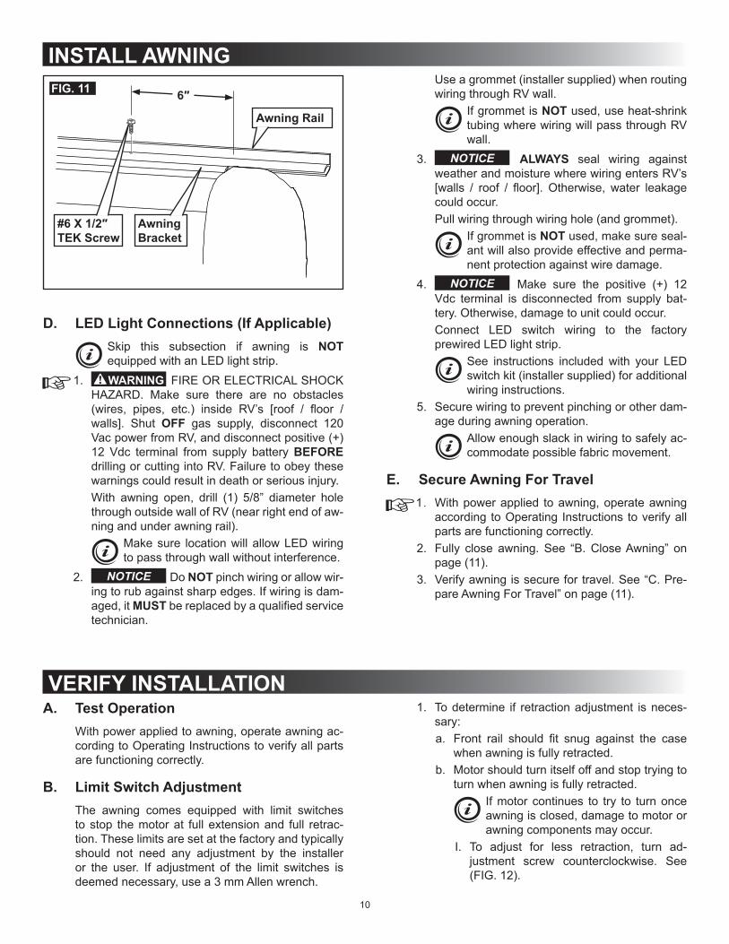
5. Secure awning with a #6 X 1/2” TEK screw (in-staller supplied) on each end of awning rail (ap-proximately 6” from awning bracket edge). See (FIG. 11).
10
INSTALL AWNINGFIG. 11 6″
Awning Bracket
Awning Rail
#6 X 1/2″ TEK Screw
D. LED Light Connections (If Applicable)Skip this subsection if awning is NOT equipped with an LED light strip.
1. FIRE OR ELECTRICAL SHOCK HAZARD. Make sure there are no obstacles (wires, pipes, etc.) inside RV’s [roof / floor / walls]. Shut OFF gas supply, disconnect 120 Vac power from RV, and disconnect positive (+) 12 Vdc terminal from supply battery BEFORE drilling or cutting into RV. Failure to obey these warnings could result in death or serious injury.With awning open, drill (1) 5/8” diameter hole through outside wall of RV (near right end of aw-ning and under awning rail).
Make sure location will allow LED wiring to pass through wall without interference.
2. Do NOT pinch wiring or allow wir-ing to rub against sharp edges. If wiring is dam-aged, it MUST be replaced by a qualified service technician.
Use a grommet (installer supplied) when routing wiring through RV wall.
If grommet is NOT used, use heat-shrink tubing where wiring will pass through RV wall.
3. ALWAYS seal wiring against weather and moisture where wiring enters RV’s [walls / roof / floor]. Otherwise, water leakage could occur.Pull wiring through wiring hole (and grommet).
If grommet is NOT used, make sure seal-ant will also provide effective and perma-nent protection against wire damage.
4. Make sure the positive (+) 12 Vdc terminal is disconnected from supply bat-tery. Otherwise, damage to unit could occur.Connect LED switch wiring to the factory prewired LED light strip.
See instructions included with your LED switch kit (installer supplied) for additional wiring instructions.
5. Secure wiring to prevent pinching or other dam-age during awning operation.
Allow enough slack in wiring to safely ac-commodate possible fabric movement.
E. Secure Awning For Travel1. With power applied to awning, operate awning
according to Operating Instructions to verify all parts are functioning correctly.
2. Fully close awning. See “B. Close Awning” on page (11).
3. Verify awning is secure for travel. See “C. Pre-pare Awning For Travel” on page (11).
VERIFY INSTALLATIONA. Test Operation
With power applied to awning, operate awning ac-cording to Operating Instructions to verify all parts are functioning correctly.
B. Limit Switch AdjustmentThe awning comes equipped with limit switches to stop the motor at full extension and full retrac-tion. These limits are set at the factory and typically should not need any adjustment by the installer or the user. If adjustment of the limit switches is deemed necessary, use a 3 mm Allen wrench.
1. To determine if retraction adjustment is neces-sary:a. Front rail should fit snug against the case
when awning is fully retracted.b. Motor should turn itself off and stop trying to
turn when awning is fully retracted.If motor continues to try to turn once awning is closed, damage to motor or awning components may occur.
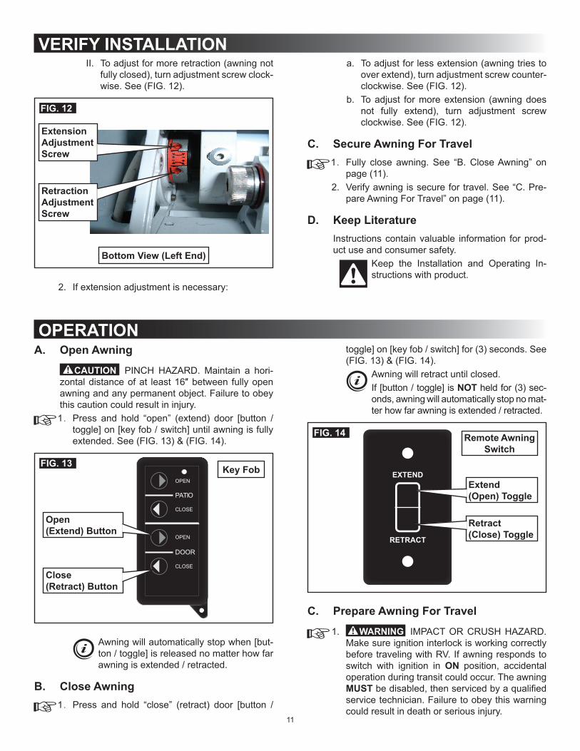
I. To adjust for less retraction, turn ad-justment screw counterclockwise. See (FIG. 12).
11
A. Open Awning
PINCH HAZARD. Maintain a hori-zontal distance of at least 16″ between fully open awning and any permanent object. Failure to obey this caution could result in injury.1. Press and hold “open” (extend) door [button /
toggle] on [key fob / switch] until awning is fully extended. See (FIG. 13) & (FIG. 14).
PATIO
DOOR
OPEN
OPEN
CLOSE
CLOSE
FIG. 13
Open(Extend) Button
Close(Retract) Button
Key Fob
Awning will automatically stop when [but-ton / toggle] is released no matter how far awning is extended / retracted.
B. Close Awning1. Press and hold “close” (retract) door [button /
toggle] on [key fob / switch] for (3) seconds. See (FIG. 13) & (FIG. 14).
Awning will retract until closed.If [button / toggle] is NOT held for (3) sec-onds, awning will automatically stop no mat-ter how far awning is extended / retracted.
EXTEND
RETRACT
FIG. 14
Extend(Open) Toggle
Retract(Close) Toggle
Remote Awning Switch
C. Prepare Awning For Travel
1. IMPACT OR CRUSH HAZARD. Make sure ignition interlock is working correctly before traveling with RV. If awning responds to switch with ignition in ON position, accidental operation during transit could occur. The awning MUST be disabled, then serviced by a qualified service technician. Failure to obey this warning could result in death or serious injury.
VERIFY INSTALLATIONII. To adjust for more retraction (awning not
fully closed), turn adjustment screw clock-wise. See (FIG. 12).
FIG. 12
Extension Adjustment Screw
Bottom View (Left End)
Retraction Adjustment Screw
2. If extension adjustment is necessary:
a. To adjust for less extension (awning tries to over extend), turn adjustment screw counter-clockwise. See (FIG. 12).
b. To adjust for more extension (awning does not fully extend), turn adjustment screw clockwise. See (FIG. 12).
C. Secure Awning For Travel1. Fully close awning. See “B. Close Awning” on
page (11).2. Verify awning is secure for travel. See “C. Pre-
pare Awning For Travel” on page (11).
D. Keep LiteratureInstructions contain valuable information for prod-uct use and consumer safety.
Keep the Installation and Operating In-structions with product.
OPERATION

12
In case of power failure, it may be necessary to close awning manually or remove awning from RV.
Rule out simple causes for power failure (RV discon-nected from power, low / discharged battery, ignition interlock, etc.) before performing power failure pro-cedures. After awning is closed manually, it may require service by a qualified service technician.
A. Close Awning Manually
PINCH HAZARD. Keep CLEAR of arm assemblies while closing awning. Arm assem-blies will [fold / close] against back rail. Failure to obey this warning could result in death or serious injury.When awning is in open position and 12 Vdc power has been lost, the awning may be closed by sup-plying auxiliary power (from external source) to aw-ning motor.
A 12 Vdc automobile battery may be used as an external power source.
1. ELECTRICAL SHOCK HAZARD. Disconnect power from product before access-ing wiring connections. There may be issues mimicking a power failure with electric current still present, or power may return unexpectedly. Failure to obey this warning could result in death or serious injury.Disconnect 120 Vdc power from RV, and 12 Vdc power to awning.
2. Unplug door motor wiring harness connector from electronic control box. See section, “AP-PENDIX A: ELECTRONIC CONTROL KIT WIR-ING” on page (15).
3. Connect 16 gauge (minimum) wire leads (user supplied) to door motor wiring harness connec-tor, and tape in place (with electrical tape).
OPERATION
Do NOT connect to electronic control box.Match wire lead colors to door motor wir-ing harness colors.BLACK wire lead to BLACK/WHITE door motor wire, and RED wire lead to RED/WHITE door motor wire.
4. Disconnect power IMMEDIATE-LY after awning retracts. Otherwise, damage to awning motor could occur.With someone watching door awning, connect other end of wire leads to the 12 Vdc external power source, until awning retracts to its closed position:a. Connect BLACK wire to positive (+) termi-
nal.The lead wire connected to positive (+) terminal MUST have a (3 A) in-line fuse installed.
b. Connect RED wire to negative (-) terminal.c. Disconnect wire leads from power source
once awning fully retracts.The awning will extend if wire leads are reversed (reversed polarity).
5. If awning responds to external power source, make sure awning is completely closed and se-cure. See subsection, “C. Prepare Awning For Travel” on page (11).
6. If awning does not respond to external power source (after confirming connections and charge on external power source), the wiring harness may have a short. Proceed to step (7).
7. Remove LH cover from awning, and unplug door motor wiring harness from awning motor wiring (connector). See (FIG. 9).
8. Connect 16 gauge (minimum) wire leads (user supplied) to awning motor wiring (connector), and tape in place (with electrical tape).
With awning fully closed, test ignition interlock system:a. With vehicle ignition in ON position, attempt
to open awning.b. If awning does not respond (remains closed),
the ignition interlock is functioning. Skip to step (3).
c. If awning responds to switch (awning opens), there is a problem with the ignition interlock system. Proceed to step (2).
2. Disable awning for travel to service center:a. Close awning and unplug door motor con-
nector from electronic control box. See sec-tion, “APPENDIX A: ELECTRONIC CON-TROL KIT WIRING” on page (15).
b. Repeat step (1) to verify motor is disabled.c. Have awning repaired by a qualified service
technician.3. Verify awning is secure for travel.
Look for loose parts, and any sign of in-stability.
CLOSE OR REMOVE AWNING (POWER FAILURE)

13
Do NOT connect to door motor wiring har-ness.Match wire lead colors to awning motor wiring colors:BLACK wire to BLACK (or BLUE) aw-ning motor wire, and RED wire to RED (or BROWN) awning motor wire.
9. Repeat steps (4) through (5).10. If awning still does NOT respond to external
power source (after confirming connections and charge on external power source), the motor may be defective. Proceed to subsection, “B. Remove Awning From RV” on page (13).
B. Remove Awning From RV1. With LH cover removed from awning, verify door
motor wiring harness is unplugged from awning motor wiring (connector). See (FIG. 9).
2. Remove the (2) #10-16 X 5/8” screws securing awning back rail to RV. See (FIG. 10).
3. Remove the #6 X 1/2” TEK screws securing aw-ning bracket to awning rail. See (FIG. 11).
4. LIFTING HAZARD. Use proper lifting technique and control when lifting product. Failure to obey this caution could result in injury.With brief help from additional personnel, care-fully move (slide) the awning from awning rail.
5. IMPACT OR PINCH HAZARD. Hold lead rail firmly while closing awning. Lead rail and lateral arm assemblies are under ten-sion from gas strut, and could extend quickly and unexpectedly if NOT controlled. Failure to obey this warning could result in death or seri-ous injury.While maintaining firm control, push lead rail back until it closes against awning casing. Then securely tie it closed (with fabric strapping or light rope).
Alternatively, several wraps of strong duct tape may be used to secure awning closed.
CLOSE OR REMOVE AWNING (POWER FAILURE)
GENERAL CARE AND USEA. Precautions
Failure to obey the following notices could damage product or property.
● Do NOT use insecticides or other sprays near awning fabric. These could cause stains, and could adversely affect fabric’s ability to repel wa-ter.
● Do NOT expose awning to adverse environmen-tal conditions, corrosive agents, or other harmful conditions.
● Do NOT allow corner of entry door to contact awning fabric. Otherwise, premature wear or tearing of awning fabric could occur.
● NEVER close awning (for storage) when wet. The combination of moisture and dirt could re-sult in mildew, discoloration, and stains.
If it is necessary to roll up awning (tempo-rarily) while it is wet, make sure you roll it out and let it dry (as soon as conditions allow) before rolling it up again.
● Do NOT allow dirt, leaves, or other debris to ac-cumulate on awning, which could cause abra-sion and stains. Mildew could grow on dirt and organic debris causing permanent discoloration, stains, and odors to awning fabric.
B. Hardware Maintenance
1. Do NOT use strong chemicals or abrasives to clean parts, as their protective sur-faces will be damaged.Clean awning hardware (as needed) with a mild surface cleaner (such as dish soap).
2. Do NOT use silicone sprays near labels. Otherwise, the label’s adhesive bond to product surfaces could weaken.Apply silicone spray lubricant as needed to keep the fabric roller tube assembly’s moving parts operating smoothly.
3. Lubricate all sliding surfaces of arm assemblies with silicone spray as needed.
C. Fabric MaintenanceVinyl fabric offers the advantage of durability and water resistance.
Wrinkling is a normal characteristic of vinyl. Wrinkling may be more noticeable when re-tracted, and after prolonged periods of stow-age (rolled up). Leave awning open during warm weather to minimize the wrinkling over a period of time.
1. To clean:a. Mix 1/4 cup dish soap and 1/4 cup bleach to
5 gallons of fresh water to use as cleaning solution.

14
b. Do NOT use abrasive or cor-rosive cleaners, mildew removers, or hard bristle brushes on awning fabric.Liberally drench open awning fabric with cleaning solution.
c. Close awning, let it soak for 5 minutes, then open awning again.
d. Remove solution COM-PLETELY from awning fabric. Bleach will degrade awning fabric if NOT completely rinsed off.Thoroughly hose off top and bottom of fabric with clean water.
Repeat as necessary to completely re-move solution.
e. NEVER close awning (for storage) when wet. The combination of moisture and dirt could result in mildew, dis-coloration, and stains.Allow awning to dry thoroughly before stow-ing (rolling up).
2. To repair a pinhole, or if a spot of coating flakes off from top layer of vinyl fabric:
a. Apply a very small dab of VLP (Vinyl Liquid Patch) on tip of cotton swab.
VLP is available from Dometic Cor-poration. Reference part number 3314216.000 when ordering.
b. Gently roll cotton swab around pinhole. The VLP will melt the coating (on fabric) and that will quickly fill in pinhole and blend with all colored vinyls.
c. NEVER close (roll up) awning when vinyl liquid patch is wet. Otherwise, damage to other parts of awning fabric (melt-ing through layers) will occur.Allow VLP to dry thoroughly before stowing (rolling up) awning.
D. When To Get More HelpIf malfunctions occur (that cannot be corrected by reviewing these instructions), contact a qualified service technician.
A slight “travel line” may appear where door roller (if installed) contacts awning fabric. This is considered normal and does NOT af-fect the integrity of awning fabric.
GENERAL CARE AND USE

15
APPENDIX A: ELECTRONIC CONTROL KIT WIRINGKITS: 3310287.002 & 3310287.010
2421181512
WIND
ON
WINDSENSOR
LIMITSWITCH
PATIOSWITCH
DOORSWITCH
PATIOMOTOR
DOORMOTOR POWER 12 VDC
+ -
U.S.A. PATENT NO 6,798,158.
EXTE
ND
RET
RA
CT
EXTE
ND
RET
RA
CT
All
Wiri
ng(In
stal
ler S
uppl
ied)
1 2 3 41 21 2 31 2 31 2 3 1 2
1 21 2 3 1 2
Plug350777-1
Plug350779-1
Plug350777-1
Plug350766-1
Plug350766-1
Plug350766-1
Plug350777-1
Plug350777-1
Plug350766-1
Socket 640310-3(10-12 AWG)
Pin 350547-1(14-20 AWG)
Pin 350547-1(14-20 AWG)
Socket 350689-1(18-24 AWG)
Pin 350547-1(14-20 AWG)
Socket 350689-1(18-24 AWG)
CapCapCap
PIN
K -
16 A
WG
BLA
CK
- 12
AW
G
RED
- 12
AW
G
*RED
*BLA
CK
*RED
/ W
HIT
E
*BLA
CK
/ W
HIT
E
GR
EEN
/ W
HIT
E - 1
6 AW
G
BR
OW
N /
WH
ITE
- 16
AWG
YELL
OW
/ W
HIT
E - 1
6 AW
G
YELL
OW
- 16
AW
G
BR
OW
N -
16 A
WG
GR
EEN
- 16
AW
G
WH
ITE
- 18
AWG
BLA
CK
- 18
AW
G
RED
- 18
AW
G
Exte
nsio
n H
arne
ss
Exte
nsio
n H
arne
ss
Posi
tive
(+) 1
2 Vd
c To
Pow
er S
uppl
yN
egat
ive
(-) 1
2 Vd
c To
Pow
er S
uppl
y
To V
ehic
le Ig
nitio
n W
ireRem
ote
Switc
hW
eath
erPr
o Pa
tio A
wni
ng(N
ot U
sed
On
Oas
is E
lite)
Rem
ote
Switc
hO
asis
Elit
e D
oor A
wni
ng(N
ot U
sed
On
Wea
ther
Pro
)
Win
d Se
nsor
Wire
Har
ness
To B
otto
m O
f RH
Arm
(Wea
ther
Pro
)
Patio
Mot
orW
ire H
arne
ssTo
Bot
tom
Of R
H A
rm(W
eath
erP
ro)
Doo
r Mot
orW
ire H
arne
ssTo
LH
Cov
er(O
asis
Elit
e)
* See “Table 1” on page (4) for wire gauge.
Socket 350550-1
(14-20 AWG)