rethinking the design process isight framework
TRANSCRIPT

Rethinking the Design Process iSIGHT Framework
Presentation to TFAWs 2001
Mark ProwDr. Therese Rhodes
Engineous Software200 CentreGreen Way, Suite 100
Cary, NC 27513919-677-6756 fax 919-677-8911

September 12, 2001 Copyright 2001 Engineous Software Slide 2
Product Creation: A Brutally Multidisciplinary Challenge!
Collaboration Across Engineering Disciplines, Organizations, Product Components and Lifecycle Stages
Mission Noise
CostElectronic
Airframe Structure
Propulsion
Airport NoiseCabin Noise
Manufacturing CostInventory/Financial CostProduct Lifecycle Cost
AerodynamicsHeat TransferStructural MechanicsStructural Dynamics
Fuel BurnEconomic AnalysisRangeTakeoff Gross Weight
Guidance/ControlCommunicationsElectric Power Supply
Engine CycleAerodynamicStructural MechanicsCombustionStructural DynamicsWeight

September 12, 2001 Copyright 2001 Engineous Software Slide 3
Design Data Islands
The Product Creation ProcessThe Product Creation Process
CADLoads
FEAFEA
CFDCFD
In-house legacy code
In-house legacy codes
In-house legacy code: COST MODELING
KinematicsThermal
Durability
Materials
In-house legacy codes
In-house legacy codes

September 12, 2001 Copyright 2001 Engineous Software Slide 4
Engineous HistoryA catalyst for engineering innovation!
1979 1983 1996
1st. Generation 2nd Generation 3rd Generation
Engineous at GE>10 Years - $12 Million
“Software Robot” at MITInvented by Dr. Tong
1996 - Engineous founded2001 - iSIGHT 6.0 released

September 12, 2001 Copyright 2001 Engineous Software Slide 5
Engineous People –Educational Snapshot
70 People Worldwide61 Degreed Engineers42 w/Advanced Engineering Degrees10 Doctorate LevelIndustry Specific Experts- Automotive and Turbo Machinery. Substantial background at GM, GE, Cray Research, and NASA.Dr. Siu Tong – Founder and ChairmanOver 20 years experience in the technology industry as a
senior manager and in product research and development.

September 12, 2001 Copyright 2001 Engineous Software Slide 6
Helping Our Customers
Help our clients integrate their diverse design tools
1.Engineous Deploys Resources and Technology
to:
Automate their iterative design processes
2.
Accelerate finding the best design solution
3.

September 12, 2001 Copyright 2001 Engineous Software Slide 7
Manual Design Evaluation Process
=Satisfied?
ModifyDesign
Execute SimulationCode(s)
Manual Design Process• Time consuming • Error prone tasks• Engineers spend more time preparing
Results• Produces limited number of designs• Produces questionable design quality• Fewer design alternatives

September 12, 2001 Copyright 2001 Engineous Software Slide 8
iSIGHT Software Robot
Manual Design Process• Time consuming • Error prone tasks• Engineers spend more time preparing
=Satisfied?
ModifyDesign
Execute SimulationCode(s)
Results• Produces limited number of designs• Produces questionable design quality• Fewer design alternatives
iSIGHT - Software Robot• Engineer defines simulation process• Engineer defines goals and constraints • Robot applies design intelligence• Automates and iterates design process • 24 hour workday
Results• Increased evaluations• Improved quality• Engineers spend more time evaluating • Multiple design alternatives• Saves valuable engineering time• Greater product knowledge

September 12, 2001 Copyright 2001 Engineous Software Slide 9
Design AutomationiSIGHT
Integrates the Process
Automates the Execution
Evaluates theAlternatives
TypicalManual Iterative
Process
Design Concept
How does iSIGHT Modify Designs?
By Applying Design Intelligence to the iterative process through Design Study Tools
o Deterministico Stochastic
Build Computer Model
Adjust Input File(s)
MeetsRequirements?
N
Y
Run Model
Review Output File(s)
Final Design

September 12, 2001 Copyright 2001 Engineous Software Slide 10
Complete Design Exploration Engine
Optimization
� Rule-based� Exploratory (GA
etc)� Gradient-based� Mixed Variable
Approx.Models
� Taylor Series� Response Surface� Variable Complexity
Design ofExperiments
� Central Composite
� Full Factorial� Orthogonal Array� Latin Hypercube� Parameter� Database
Deterministic Methods
Deterministic Methods
QualityEngineering
� Monte Carlo� Taguchi Robust
Design� Reliability Analysis� Reliability-based
Optimization� Design for Six Sigma
Stochastic Methods
Stochastic Methods

September 12, 2001 Copyright 2001 Engineous Software Slide 11
New Design Process
Y1
ConstraintBoundary
Initial Design
Search for solutionOptimization
(Approximations)
Robust/Reliability Design(Quality Engineering)
Feasible Infeasible (safe) (failed)X2
X1
DOE:Critical Factors
And Initial Design
Y2

September 12, 2001 Copyright 2001 Engineous Software Slide 12
GUI InterfaceTask Manager
File Parser
Automate/Integrate
Define ConstraintsMonitor
DOE Post-Processing

September 12, 2001 Copyright 2001 Engineous Software Slide 13
Connectivity A Sampling of Applications in Use at Our Customer Sites
ASCII-based I/O Files using iSIGHT GUIStructures: NASTRAN, MARC, ABAQUS, ANSYSMetal Forming: DEFORM, ProcastCFD: STAR-CD, FLUENT, CFX, TASCflow, STREAMCrash/Impact: Pam-Crash, LS-DYNA, RADIOSS, MADIMOInjection Molding: MOLDFLOW, C-Mold, TIMON, PLANETS, SimVisMagnetics/Acoustics/Optics: CODE-VMech. Dynamics/Control: ADAMS, DADS, Matlab, Matrix-XEngines: GT-Power, BoostSemiconductors: SPICECAD/Pre-Processor: I-DEAS, Pro/E, Unigraphics, CATIA, PATRAN,
Acumen, Hyper-Mesh, Gridgen, HICAD/CADAS etc.Turbomachinery Concepts NREC COMPAL, CCADThermo Cycle Analysis Legacy codes at GE, Toshiba, Honeywell, P&W, etc.General Math/Plotting: Mathcad, S-PLUSMany Internal Programs

September 12, 2001 Copyright 2001 Engineous Software Slide 14
Platform UtilizationUnixSun, SGI, HP, IBM, etc.
WindowsNT, 2000
Linux
Parallel and Distributed ProcessingRun multiple codes in parallelRun parallel techniques (i.e., DOE, GA)Distributed and enabled across heterogeneous network

September 12, 2001 Copyright 2001 Engineous Software Slide 15
Application ExamplesMulti-Stage Power Generator Steam TurbineDARPA: Integrated Disk Design & ManufacturingDARPA AIM (Project for Accelerated Insertion of Materials)Airframe/Propulsion OptimizationNavy Propeller Conceptual DesignAerospike Nozzle DesignAmerica’s Cup Yacht Design Prada’s Luna Rossa

September 12, 2001 Copyright 2001 Engineous Software Slide 16
Multi-Stage Power Generator Steam TurbineProblem: Reduce time required to design power plant turbines
Solution: Use Engineous software to integrate 29 codes
Result:• Design time reduced
from 1 year to hours• Major competitive
advantage for GE Power Systems

September 12, 2001 Copyright 2001 Engineous Software Slide 17
Multi-Stage Power Generator Steam Turbine
Refined Cascade Design
Airfoil Generator 1Airfoil Generator 2Cascade Analysis
Airfoil Stacking
Initial Cascade Design
Airfoil Generator 1Airfoil Generator 2Cascade Analysis
Airfoil Stacking
Mechanical DesignPre-Processor A
Pre-Processor B
Pre-Processor C
ANSYS
V-Mode Identification
Initial CircumferentialDesign
Turbine Initialization
Flowpath Smoothing
Calculate Intersection
Turbine Update
Cirm-preprocessorI/O manipulationCircum-analysis
Refined CircumferentialDesign
Post-Processor 1
Post-Processor 2
Update Intersection
Turbine Update
Cirm-preprocessorI/O manipulationCircum-analysis
Flowpath Generation
Axial Pre-Processing
Predict Efficiency
Preliminary Design

September 12, 2001 Copyright 2001 Engineous Software Slide 18
DARPA Program Integrated Turbine Disk Design
Objective:Demonstrate geometry and finite element based multidisciplinary optimization (MDO) for complex product and process development

September 12, 2001 Copyright 2001 Engineous Software Slide 19
DARPA: Integrated Disk Design & Manufacturing
Design Manufacturing
Requirements
MechanicalDesign
Forging HeatTreatme
nt
LifePredictio
n
Machining
FinishedPart
Die(s)
Billet
ProcessParameters
Finished Part
HCF/LCFData
• Geometry• Material
• Residual Stress• Distortions
• ResidualStress
• MaterialProperties
ProcessParameters Near-net Shape
Disk Forging
• Part Life ProcessParameters

September 12, 2001 Copyright 2001 Engineous Software Slide 20
DARPA: Integrated Disk Design & Manufacturing
Mechanical DesignMeet RequirementsMinimize WeightMinimize Cost
ForgingNear Net ShapeMinimize Forging
OperationsFormability
Heat TreatmentRequisite Material PropertiesMinimize Residual StressNo Cracking
MachiningMinimize DistortionMinimize Number of Operations
Life predictionRequired Life

September 12, 2001 Copyright 2001 Engineous Software Slide 21
DARPA: Integrated Disk Design & Manufacturing
CL
axial distortion
The Problem: Residual Stresses Introducedduring Heat Treatment lead to distortions of the Finished Part
h1
h2h3 h4
h5
h6
h7h8
h9
h10
Minimize Non-uniform Cooling for Reduced Residual StressesCooling Rate Constraints for CreepPerformanceSurface Heat Transfer Coefficients hi
The Tools: iSIGHT Finite Element Analysis(DEFORM)
Cooling Rate Optimization
September 12, 2001 Copyright 2001 Engineous Software Slide 22
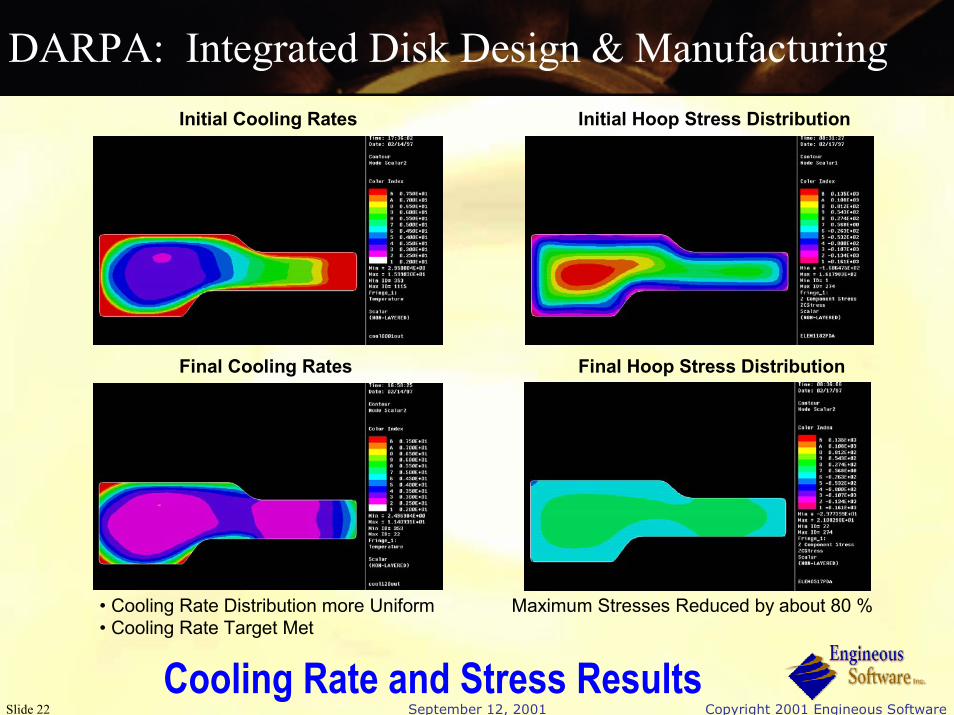
DARPA: Integrated Disk Design & ManufacturingInitial Cooling Rates Initial Hoop Stress Distribution
Final Cooling Rates Final Hoop Stress Distribution
• Cooling Rate Distribution more Uniform• Cooling Rate Target Met
Maximum Stresses Reduced by about 80 %
Cooling Rate and Stress Results

September 12, 2001 Copyright 2001 Engineous Software Slide 23
DARPA: Integrated Disk Design & Manufacturing
Forging Die Speed Optimization Objective:To forge the billet into a high pressure turbine disk such that the maximum strain rate in the deformable work piece never exceeds 0.008 s-1
during forging.

September 12, 2001 Copyright 2001 Engineous Software Slide 24
DARPA: Integrated Disk Design & Manufacturing
Conventional Approach Results Optimized Approach Results
Forging Die Speed Optimization:Equivalent Strain Rate Contours

September 12, 2001 Copyright 2001 Engineous Software Slide 25
DARPA: Integrated Disk Design & Manufacturing
iSIGHT DEFORMUnigraphics
Forging Die Shape Optimization

September 12, 2001 Copyright 2001 Engineous Software Slide 26
DARPA: Integrated Disk Design & Manufacturing
The strain distributions of the initial and optimal designs. The low strain region is reduced in the optimal design. All data
is normalized.
Forging Die Shape Optimization:Normalized Strain Distributions

September 12, 2001 Copyright 2001 Engineous Software Slide 27
DARPA: Integrated Disk Design & Manufacturing
High Pressure Turbine Disk Stage 9 Compressor Disk
Stage 1 Fan Disk
Summary:• Forging Optimization System Has
Been Applied to Several Disks
• Demonstrated Weight Reductions of 11% (average) Over Manually Optimized Designs
• Transition of Software to Forging Vendors In-Progress Forward Seal

September 12, 2001 Copyright 2001 Engineous Software Slide 28
DARPA AIM (Project for Accelerated Insertion of Materials)
Goal:Develop a rotor component design
system - called “aimSIGHT” - that allows material forming process parameters to be tuned automatically to achieve desired material properties and component performance, thereby dramatically reducing the time needed to develop new materials
Account for real world uncertainties in manufacturing process, material properties, tolerances, material behavior predictions, etc.
Team Members:Pratt & Whitney (Lead)Scientific Forming Technologies Corp.Ladish Co.Engineous Software Inc.Brown UniversityCarnegie-Mellon UniversityUniversity of ConnecticutDrexel University Lehigh UniversityUniversity of MichiganMichigan Technological UniversityMITNorthwestern UniversityWest Virginia University

September 12, 2001 Copyright 2001 Engineous Software Slide 29
“aimSIGHT” Design System
Define/Modify Geometry
Define/Modify Geometry
Select forging process and
heat treatment parameters
Select forging process and
heat treatment parameters
Predict deformation and thermal behavior
Predict deformation and thermal behavior
Predict microstructure
Predict microstructure
Predictlife
Predictlife
Performance & cost
criteria met?
Performance & cost
criteria met?
Part DefinitionPart Definition
NEW
Predict material properties
Predict material properties
NEW
DEFORMANSYS
Unigraphics
Entire Process Driven by iSIGHT
NO
YES
MachiningMachining
ForgingForging
InspectionInspection
MaterialMaterial
Predictcost
Cost AdvantageTMUnderDevelopment

September 12, 2001 Copyright 2001 Engineous Software Slide 30
Airframe/Propulsion Optimization
The Problem:Determine the optimal cycle and minimum engine size to match a given engine to an airframe for optimal aircraft performance.

September 12, 2001 Copyright 2001 Engineous Software Slide 31
Integrated Airframe/Propulsion OptimizationObjective: Determine the optimal cycle and minimum engine size to match a
given engine to an airframe for optimal aircraft performance.

September 12, 2001 Copyright 2001 Engineous Software Slide 32
Integrated Airframe/Propulsion Optimization
Conclusion: Design optimization using preliminary design tools allows efficient evaluation of complex engineering systems & scenarios that can improve designs to achieve enhanced performance and reduce cycle times at lower cost

September 12, 2001 Copyright 2001 Engineous Software Slide 33
Integrated Airframe/Propulsion Optimization
0.30.3 0.46 0.62 0.78 0.94 1.1
1.0 FPR0.9
0.75
Min. Core Speed
0.42 FPR
0.6
0.5
Core Speed Margin
0.1 BPR
1.0 BPR
0
0.3
0.6
1.0
1.3
0 10 20 30 40 50
1.62.2
0.4
0.5
0.6
0.7
0.8
0.9
1.0
1.1
1.8
1.4
1.0

September 12, 2001 Copyright 2001 Engineous Software Slide 34
Navy Propeller Conceptual DesignConcept
LoadingSkewPitchChordCamberSection ShapeThickness
# BladesNose RadiusDiameter
Acoustic NoiseStructural Integrity
Weight
Propulsion Efficiency
VibrationForces & Moments
Cavitation
The Problem:Balancing the competing design requirements and constraintsof 6 engineering groups to create the best overall propeller

September 12, 2001 Copyright 2001 Engineous Software Slide 35
Navy Propeller Conceptual Design
Benefits
• Better Design in Reduced Time• Typical Single-Screw Propeller Design
Manual Engineous
Average PreliminaryDesign Time: 2 Months
Average PreliminaryDesign Time: 3 Weeks
Limited Number ofDesign Alternatives Evaluated
10-100 Times MoreDesign Alternatives Evaluated
70% of Time Spent PreparingDesign Alternatives
30% of Time Spent Evaluating andEngineering Design Alternatives
5% of Time Spent PreparingDesign Alternatives
95% of Time Spent Evaluating andEngineering Design Alternatives

September 12, 2001 Copyright 2001 Engineous Software Slide 36
Aerospike Nozzle DesignNASA Langley
Problem: Minimize the Gross Lift-off Weight. Requires modeling effects of 4 domains, namely structures, CFD, baseflow, and performance domains18 design variables, 564 constraintsSolution: Coupled iSIGHT with multiple codes and implemented multidisciplinary feasible (MDF) strategy Results:“iSIGHT reduces code and file management for the user”“iSIGHT reduces time required to explore variety of optimization schemes and design parameters”

September 12, 2001 Copyright 2001 Engineous Software Slide 37
Trim Optimization
Parametric Design
Variables
ICEMCFDMesh
ICEMCFDMesh
Optimize yacht position (trim) to minimize drag and maximize speed for given sea surface shape
Select trim
iSIGHTiSIGHTiSIGHT
Pro/EGeometry
Pro/ESeaSurfaceSea
Surface GeometryModel hull and
sea shapeCreate meshes
Pro/MechanicaMotion
FLOWLOGICCFD
Pro/Mechanica FLOWLOGICConvergeOptimum Motion CFD
Simulate motionof hull in water
Calculate dragMin drag, max speed?

September 12, 2001 Copyright 2001 Engineous Software Slide 38
Automating Hull Design
1000’s of configurations analyzed in CFD
20-50 per day
iSIGHT-based design system directly optimizes Pro/ENGINEER model
Final result:
Correct new 3-D Pro/E geometry for manufacturing, no prototyping!

September 12, 2001 Copyright 2001 Engineous Software Slide 39
The Future is now!
September 12, 2001 Copyright 2001 Engineous Software Slide 40
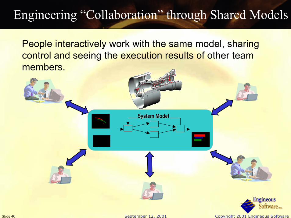
Engineering “Collaboration” through Shared Models
People interactively work with the same model, sharing control and seeing the execution results of other team members.
System ModelSystem Model

September 12, 2001 Copyright 2001 Engineous Software Slide 41
iSIGHT Collaboration
iSIGHTiSIGHTModelModel
System ModelSystem Model
331122
iSIGHT Collaborator (ISC)
PrimeContractor
ISCISC
iSIGHTiSIGHTModelModel
HTTPHTTP--XML
ISCISC
iSIGHTiSIGHTModelModel
XML
Subcontractor2
InternetInternet
Subcontractor1

September 12, 2001 Copyright 2001 Engineous Software Slide 42
Next StepDevelop a “Federated Intelligent ProductEnviRonment” (FIPER) that allows companies to globally —
� Collaborate with dispersed design teams and business partners
� Establish standard language protocol for all design tools, legacy data and systems
� Access best-of-breed design and analysis tools
� Automate non-creative tasks in the design process
FIPER�Client

September 12, 2001 Copyright 2001 Engineous Software Slide 43
What is FIPERA NIST sponsored and funded ($21.5M) project to develop:An internet-based distributed framework� Supports collaboration among geographically distributed
engineering and business partners.A service-oriented product development environment� Provides an open flexible design environment which allows
universal availability and incorporation of existing data, tools/methods and processes as services.
� Provides a common way to model your analysis and design process in conjunction with your product data.

September 12, 2001 Copyright 2001 Engineous Software Slide 44
FIPER Consortium
www.fiperproject.com

September 12, 2001 Copyright 2001 Engineous Software Slide 45
SummaryiSIGHT provides a framework which:
Enables data exchange between applications in similar or diverse disciplines.Automates the iterative nature of the design processApplicable in all stages of the design process.Allows for automation and design exploration on the component, subsystem, and/or system levelAllows users to quickly couple and drive their design and analysis tools of choice, use “best in class” for each disciplineProvides a set of tools to explore design alternatives and improvements

September 12, 2001 Copyright 2001 Engineous Software Slide 46
ConclusionsUtilization of the iSIGHT Framework throughout the design process (especially at the early conceptual design stage) has dramatic effects on:Lowering CostsImproving Safety and ReliabilityReducing Design Cycle TimeImproving QualityImproving Manufacturability
SLI (2nd gen) goals: Reduce cost of launch to low earth orbit to $1,000 per pound of payload Improve safety of loss of crew to 1 in 10,000 flights