reticulated timber dome structural system using...
TRANSCRIPT
Reticulated Timber Dome Structural System Using Glulam with a Low Specific Gravity and its Scalability
YUTAKA IIMURA
Director of Timber Engineering Div. Miyazaki Prefectural Wood Utilization Research Center
Miyakonojyo-City, Miyazaki, 885-0037, Japan SUSUMU KURITA
Manger of Structural Design Division Daiken Sekkei, Inc.
Hukuoka- City, Hukuoka,812-0011, Japan TETSUYA OHTSUKA
Structural Design Division Daiken Sekkei, Inc.
Hukuoka- City, Hukuoka,812-0011, Japan
Summary
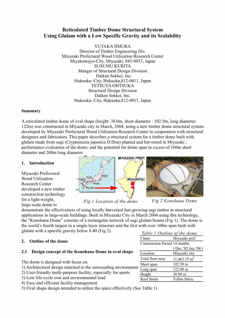
A reticulated timber dome of oval shape (height: 38.0m, short diameter : 102.5m, long diameter: 122m) was constructed in Miyazaki city in March, 2004, using a new timber dome structural system developed by Miyazaki Prefectural Wood Utilization Research Center in cooperation with structural designers and fabricators. This paper describes a structural system for a timber dome built with glulam made from sugi (Cryptomeria japonica D.Don) planted and harvested in Miyazaki ; performance evaluation of the dome; and the potential for dome span in excess of 160m short diameter and 200m long diameter. 1. Introduction Miyazaki Prefectural Wood Utilization Research Center developed a new timber construction technology for a light-weight, large-scale dome to demonstrate the effectiveness of using locally harvested fast-growing sugi timber in structural applications in large-scale buildings. Built in Miyazaki City in March 2004 using this technology, the "Konohana Dome” consists of a rectangular network of sugi glulam beams (Fig 1). The dome is the world’s fourth largest in a single-layer structure and the first with over 100m span built with glulam with a specific gravity below 0.40 (Fig 2). 2. Outline of the dome 2.1 Design concept of the Konohana Dome in oval shape The dome is designed with focus on: 1) Architectural design matched to the surrounding environment 2) User-friendly multi-purpose facility, especially for sports 3) Low life-cycle cost and environmental load 4) Easy and efficient facility management 5) Oval shape design intended to utilize the space effectively (See Table 1).
Fig 1 Location of the dome Fig 2 Konohana Dome
Table 1 Outline of the dome Client Miyazaki pref.Construction Period 14 months
( Dec.’02-Jan.’04 )Location Miyazaki cityTotal floor area 11,463.19 m2
Short span 102.50 mLong span 122.00 mHeight 38.00 mRoof finish Teflon fabric
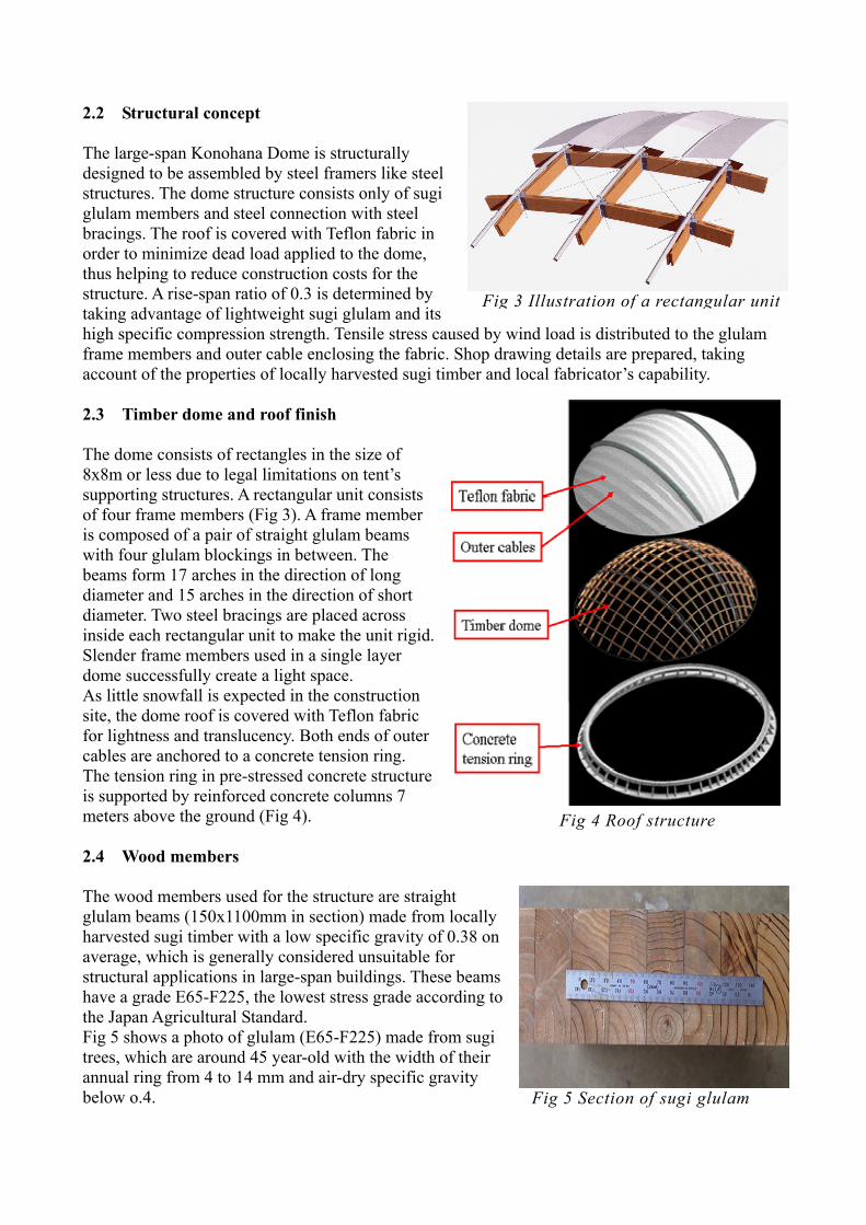
2.2 Structural concept The large-span Konohana Dome is structurally designed to be assembled by steel framers like steel structures. The dome structure consists only of sugi glulam members and steel connection with steel bracings. The roof is covered with Teflon fabric in order to minimize dead load applied to the dome, thus helping to reduce construction costs for the structure. A rise-span ratio of 0.3 is determined by taking advantage of lightweight sugi glulam and its high specific compression strength. Tensile stress caused by wind load is distributed to the glulam frame members and outer cable enclosing the fabric. Shop drawing details are prepared, taking account of the properties of locally harvested sugi timber and local fabricator’s capability. 2.3 Timber dome and roof finish The dome consists of rectangles in the size of 8x8m or less due to legal limitations on tent’s supporting structures. A rectangular unit consists of four frame members (Fig 3). A frame member is composed of a pair of straight glulam beams with four glulam blockings in between. The beams form 17 arches in the direction of long diameter and 15 arches in the direction of short diameter. Two steel bracings are placed across inside each rectangular unit to make the unit rigid. Slender frame members used in a single layer dome successfully create a light space. As little snowfall is expected in the construction site, the dome roof is covered with Teflon fabric for lightness and translucency. Both ends of outer cables are anchored to a concrete tension ring. The tension ring in pre-stressed concrete structure is supported by reinforced concrete columns 7 meters above the ground (Fig 4). 2.4 Wood members The wood members used for the structure are straight glulam beams (150x1100mm in section) made from locally harvested sugi timber with a low specific gravity of 0.38 on average, which is generally considered unsuitable for structural applications in large-span buildings. These beams have a grade E65-F225, the lowest stress grade according to the Japan Agricultural Standard. Fig 5 shows a photo of glulam (E65-F225) made from sugi trees, which are around 45 year-old with the width of their annual ring from 4 to 14 mm and air-dry specific gravity below o.4.
Fig 3 Illustration of a rectangular unit
Fig 5 Section of sugi glulam
Fig 4 Roof structure
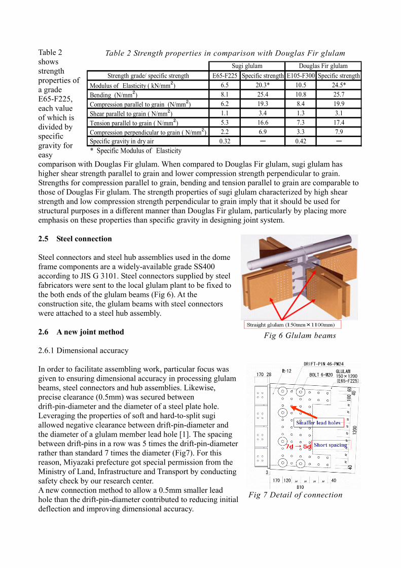
Table 2 shows strength properties of a grade E65-F225, each value of which is divided by specific gravity for easy comparison with Douglas Fir glulam. When compared to Douglas Fir glulam, sugi glulam has higher shear strength parallel to grain and lower compression strength perpendicular to grain. Strengths for compression parallel to grain, bending and tension parallel to grain are comparable to those of Douglas Fir glulam. The strength properties of sugi glulam characterized by high shear strength and low compression strength perpendicular to grain imply that it should be used for structural purposes in a different manner than Douglas Fir glulam, particularly by placing more emphasis on these properties than specific gravity in designing joint system. 2.5 Steel connection Steel connectors and steel hub assemblies used in the dome frame components are a widely-available grade SS400 according to JIS G 3101. Steel connectors supplied by steel fabricators were sent to the local glulam plant to be fixed to the both ends of the glulam beams (Fig 6). At the construction site, the glulam beams with steel connectors were attached to a steel hub assembly. 2.6 A new joint method 2.6.1 Dimensional accuracy In order to facilitate assembling work, particular focus was given to ensuring dimensional accuracy in processing glulam beams, steel connectors and hub assemblies. Likewise, precise clearance (0.5mm) was secured between drift-pin-diameter and the diameter of a steel plate hole. Leveraging the properties of soft and hard-to-split sugi allowed negative clearance between drift-pin-diameter and the diameter of a glulam member lead hole [1]. The spacing between drift-pins in a row was 5 times the drift-pin-diameter rather than standard 7 times the diameter (Fig7). For this reason, Miyazaki prefecture got special permission from the Ministry of Land, Infrastructure and Transport by conducting safety check by our research center. A new connection method to allow a 0.5mm smaller lead hole than the drift-pin-diameter contributed to reducing initial deflection and improving dimensional accuracy.
Fig 6 Glulam beams
Fig 7 Detail of connection
Table 2 Strength properties in comparison with Douglas Fir glulam
Strength grade/ specific strength E65-F225 Specific strength E105-F300 Specific strength Modulus of Elasticity ( kN/mm2) 6.5 20.3* 10.5 24.5* Bending (N/mm2) 8.1 25.4 10.8 25.7 Compression parallel to grain (N/mm2) 6.2 19.3 8.4 19.9 Shear parallel to grain ( N/mm2) 1.1 3.4 1.3 3.1 Tension parallel to grain ( N/mm2) 5.3 16.6 7.3 17.4 Compression perpendicular to grain ( N/mm2) 2.2 6.9 3.3 7.9 Specific gravity in dry air 0.32 ー 0.42 ー
* Specific Modulus of Elasticity
Sugi glulam Douglas Fir glulam
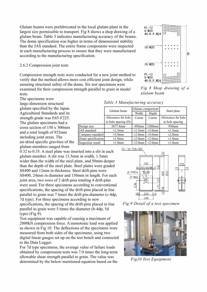
Glulam beams were prefabricated in the local glulam plant in the largest size permissible to transport. Fig 8 shows a shop drawing of a glulam beam. Table 3 indicates manufacturing accuracy of the beams. The dome specification was higher in terms of dimensional stability than the JAS standard. The entire frame components were inspected in each manufacturing process to ensure that they were manufactured according to the manufacturing specification. 2.6.2 Compression joint tests Compression strength tests were conducted for a new joint method to verify that the method allows more cost efficient joint design, while ensuring structural safety of the dome. Six test specimens were examined for their compression strength parallel to grain in model tests. The specimens were large-dimension structural glulam specified by the Japan Agricultural Standards and its strength grade was E65-F225. The glulam specimens had a cross section of 150 x 300mm and a total length of 852mm including joint areas. The air-dried specific gravities of the glulam members ranged from 0.32 to 0.35. A steel plate was inserted into a slit in each glulam member. A slit was 13.5mm in width, 1.5mm wider than the width of the steel plate, and 50mm deeper than the depth of the steel plate. Steel plates were graded SS400 and 12mm in thickness. Steel drift-pins were SS400, 24mm in diameter and 150mm in length. For each joint area, two rows of 2 drift-pins totaling 4 drift-pins were used. For three specimens according to conventional specifications, the spacing of the drift-pins placed in line parallel to grain was 7 times the drift-pin-diameter (c-4dp, 7d type). For three specimens according to new specifications, the spacing of the drift-pins placed in line parallel to grain were 5 times the diameter (b-4dp, 5d type) (Fig 9). Test equipment was capable of causing a maximum of 2000kN compression force. A monotonic load was applied as shown in Fig 10. The deflections of the specimens were measured from both sides of the specimens, using two digital linear gauges set up on the test bench and connected to the Data Logger. For 7d type specimens, the average value of failure loads obtained by compression tests was 7.0 times the long-term allowable shear strength parallel to grain. The value was determined by the below-mentioned equation based on the
Fig 9 Detail of a test specimen
Fig10 Test Equipment
Fig 8 Shop drawing of a glulam beam
Width DepthCenter Center
Design size 5677.8mm 450mm 1200mm 930mmJAS standard ±1.5mm ±1.5mm ±5.0mm ±1.5mmCompany-standard ±5.0mm ±2.0mm ±4.0mm ±2.0mmDome specification ±1.0mm ±2.0mm ±2.0mm ±1.0mmInspection result ±1.0mm ±2.0mm ±2.0mm ±1.0mm
Glulam beam
Allowance for holeto hole spacing (D)
Glulam compornent Steel plate
Allowance for holeto hole spacing
Table 3 Manufacturing accuracy
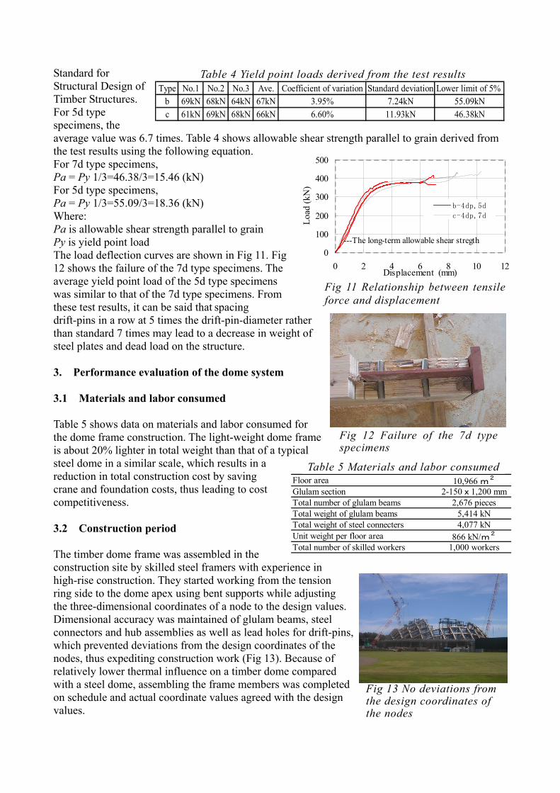
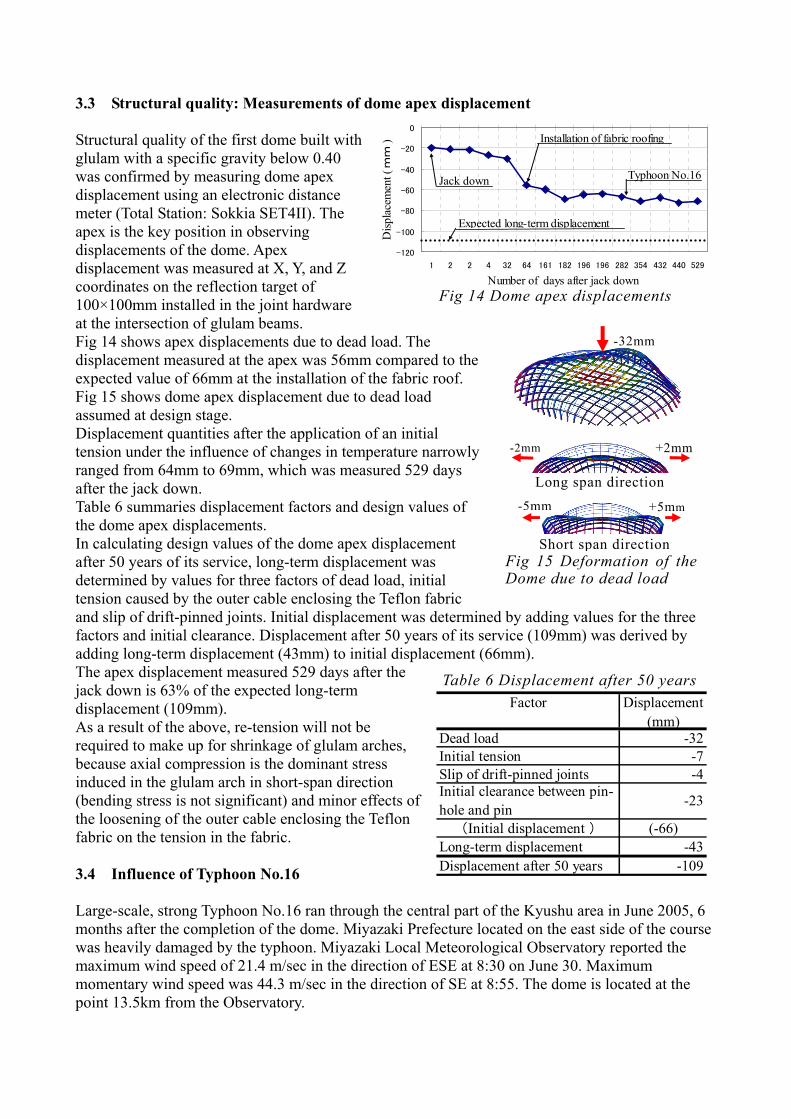
Standard for Structural Design of Timber Structures. For 5d type specimens, the average value was 6.7 times. Table 4 shows allowable shear strength parallel to grain derived from the test results using the following equation. For 7d type specimens, Pa = Py 1/3=46.38/3=15.46 (kN) For 5d type specimens, Pa = Py 1/3=55.09/3=18.36 (kN) Where: Pa is allowable shear strength parallel to grain Py is yield point load The load deflection curves are shown in Fig 11. Fig 12 shows the failure of the 7d type specimens. The average yield point load of the 5d type specimens was similar to that of the 7d type specimens. From these test results, it can be said that spacing drift-pins in a row at 5 times the drift-pin-diameter rather than standard 7 times may lead to a decrease in weight of steel plates and dead load on the structure. 3. Performance evaluation of the dome system 3.1 Materials and labor consumed Table 5 shows data on materials and labor consumed for the dome frame construction. The light-weight dome frame is about 20% lighter in total weight than that of a typical steel dome in a similar scale, which results in a reduction in total construction cost by saving crane and foundation costs, thus leading to cost competitiveness. 3.2 Construction period The timber dome frame was assembled in the construction site by skilled steel framers with experience in high-rise construction. They started working from the tension ring side to the dome apex using bent supports while adjusting the three-dimensional coordinates of a node to the design values. Dimensional accuracy was maintained of glulam beams, steel connectors and hub assemblies as well as lead holes for drift-pins, which prevented deviations from the design coordinates of the nodes, thus expediting construction work (Fig 13). Because of relatively lower thermal influence on a timber dome compared with a steel dome, assembling the frame members was completed on schedule and actual coordinate values agreed with the design values.
---The long-term allowable shear stregth0
100
200
300
400
500
0 2 4 6 8 10 12Displacement (mm)
Load
(kN
)
b-4dp,5d
c-4dp,7d
Fig 11 Relationship between tensile force and displacement
Fig 12 Failure of the 7d type specimens
Floor area 10,966 m2
Glulam section 2-150x1,200 mmTotal number of glulam beams 2,676 piecesTotal weight of glulam beams 5,414 kNTotal weight of steel connecters 4,077 kNUnit weight per floor area 866 kN/m2
Total number of skilled workers 1,000 workers
Table 5 Materials and labor consumed
Fig 13 No deviations from the design coordinates of the nodes
Table 4 Yield point loads derived from the test results Type No.1 No.2 No.3 Ave. Coefficient of variation Standard deviation Lower limit of 5%
b 69kN 68kN 64kN 67kN 3.95% 7.24kN 55.09kNc 61kN 69kN 68kN 66kN 6.60% 11.93kN 46.38kN
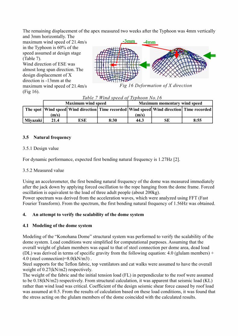
3.3 Structural quality: Measurements of dome apex displacement Structural quality of the first dome built with glulam with a specific gravity below 0.40 was confirmed by measuring dome apex displacement using an electronic distance meter (Total Station: Sokkia SET4II). The apex is the key position in observing displacements of the dome. Apex displacement was measured at X, Y, and Z coordinates on the reflection target of 100×100mm installed in the joint hardware at the intersection of glulam beams. Fig 14 shows apex displacements due to dead load. The displacement measured at the apex was 56mm compared to the expected value of 66mm at the installation of the fabric roof. Fig 15 shows dome apex displacement due to dead load assumed at design stage. Displacement quantities after the application of an initial tension under the influence of changes in temperature narrowly ranged from 64mm to 69mm, which was measured 529 days after the jack down. Table 6 summaries displacement factors and design values of the dome apex displacements. In calculating design values of the dome apex displacement after 50 years of its service, long-term displacement was determined by values for three factors of dead load, initial tension caused by the outer cable enclosing the Teflon fabric and slip of drift-pinned joints. Initial displacement was determined by adding values for the three factors and initial clearance. Displacement after 50 years of its service (109mm) was derived by adding long-term displacement (43mm) to initial displacement (66mm). The apex displacement measured 529 days after the jack down is 63% of the expected long-term displacement (109mm). As a result of the above, re-tension will not be required to make up for shrinkage of glulam arches, because axial compression is the dominant stress induced in the glulam arch in short-span direction (bending stress is not significant) and minor effects of the loosening of the outer cable enclosing the Teflon fabric on the tension in the fabric. 3.4 Influence of Typhoon No.16 Large-scale, strong Typhoon No.16 ran through the central part of the Kyushu area in June 2005, 6 months after the completion of the dome. Miyazaki Prefecture located on the east side of the course was heavily damaged by the typhoon. Miyazaki Local Meteorological Observatory reported the maximum wind speed of 21.4 m/sec in the direction of ESE at 8:30 on June 30. Maximum momentary wind speed was 44.3 m/sec in the direction of SE at 8:55. The dome is located at the point 13.5km from the Observatory.
-120
-100
-80
-60
-40
-20
0
1 2 2 4 32 64 161 182 196 196 282 354 432 440 529
Disp
lace
men
t ( m
m )
Expected long-term displacement
Jack down
Installation of fabric roofing
Typhoon No.16
Number of days after jack downFig 14 Dome apex displacements
Fig 15 Deformation of the Dome due to dead load
-32mm
Short span direction
-5mm +5mm
Long span direction
-2mm +2mm
Table 6 Displacement after 50 yearsFactor Displacement
(mm)Dead load -32Initial tension -7Slip of drift-pinned joints -4
(Initial displacement ) (-66)Long-term displacement -43Displacement after 50 years -109
Initial clearance between pin-hole and pin -23
The remaining displacement of the apex measured two weeks after the Typhoon was 4mm vertically and 3mm horizontally. The maximum wind speed of 21.4m/s in the Typhoon is 60% of the speed assumed at design stage (Table 7). Wind direction of ESE was almost long span direction. The design displacement of X direction is -13mm at the maximum wind speed of 21.4m/s (Fig 16).
3.5 Natural frequency 3.5.1 Design value For dynamic performance, expected first bending natural frequency is 1.27Hz [2]. 3.5.2 Measured value Using an accelerometer, the first bending natural frequency of the dome was measured immediately after the jack down by applying forced oscillation to the rope hanging from the dome frame. Forced oscillation is equivalent to the load of three adult people (about 200kg). Power spectrum was derived from the acceleration waves, which were analyzed using FFT (Fast Fourier Transform). From the spectrum, the first bending natural frequency of 1.56Hz was obtained. 4. An attempt to verify the scalability of the dome system 4.1 Modeling of the dome system Modeling of the “Konohana Dome” structural system was performed to verify the scalability of the dome system. Load conditions were simplified for computational purposes. Assuming that the overall weight of glulam members was equal to that of steel connection per dome area, dead load (DL) was derived in terms of specific gravity from the following equation: 4.0 (glulam members) + 4.0 (steel connection)=8.0(kN/m3) . Steel supports for the Teflon fabric, top ventilators and cat walks were assumed to have the overall weight of 0.27(kN/m2) respectively. The weight of the fabric and the initial tension load (FL) in perpendicular to the roof were assumed to be 0.18(kN/m2) respectively. From structural calculation, it was apparent that seismic load (KL) rather than wind load was critical. Coefficient of the design seismic shear force caused by roof load was assumed at 0.5. From the results of calculation based on these load conditions, it was found that the stress acting on the glulam members of the dome coincided with the calculated results.
Table 7 Wind speed of Typhoon No.16
The spot Wind speed Wind direction Time recorded Wind speed Wind direction Time recorded(m/s) (m/s)
Miyazaki 21.4 ESE 8:30 44.3 SE 8:55
Maximum wind speed Maximum momentary wind speed
-3mm -4mm-3mm-3mm -4mm-4mm
Fig 16 Deformation of X direction
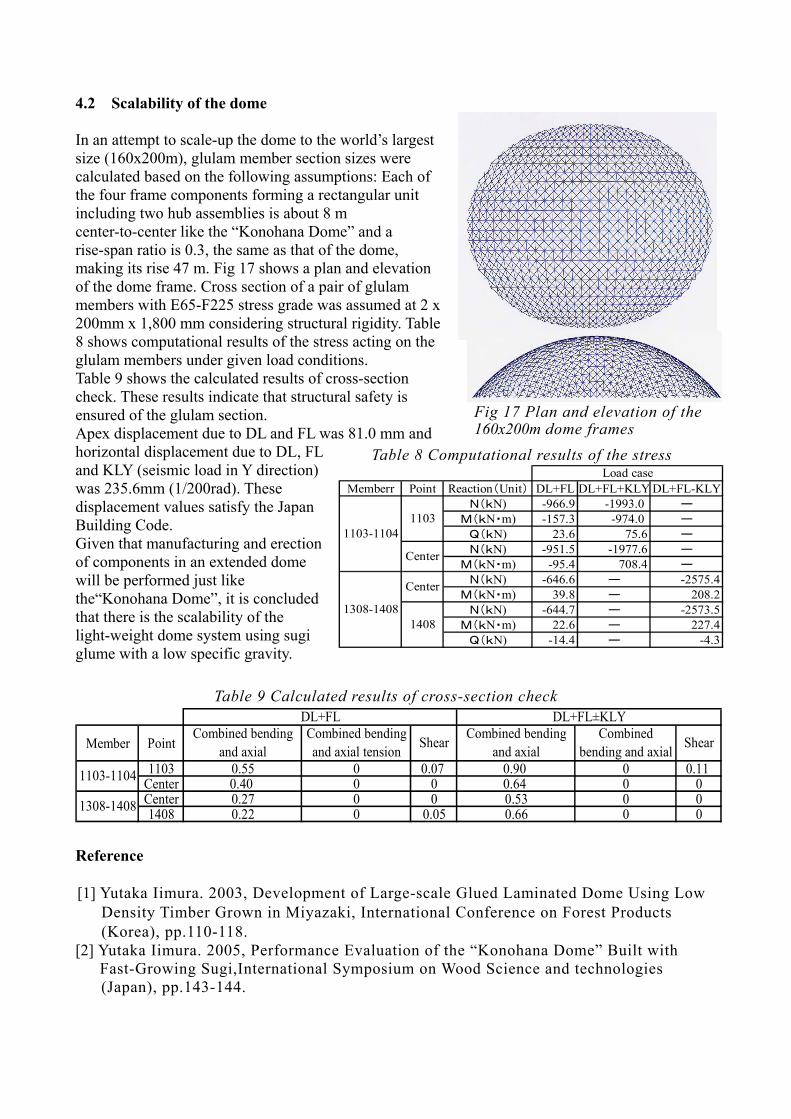
4.2 Scalability of the dome In an attempt to scale-up the dome to the world’s largest size (160x200m), glulam member section sizes were calculated based on the following assumptions: Each of the four frame components forming a rectangular unit including two hub assemblies is about 8 m center-to-center like the “Konohana Dome” and a rise-span ratio is 0.3, the same as that of the dome, making its rise 47 m. Fig 17 shows a plan and elevation of the dome frame. Cross section of a pair of glulam members with E65-F225 stress grade was assumed at 2 x 200mm x 1,800 mm considering structural rigidity. Table 8 shows computational results of the stress acting on the glulam members under given load conditions. Table 9 shows the calculated results of cross-section check. These results indicate that structural safety is ensured of the glulam section. Apex displacement due to DL and FL was 81.0 mm and horizontal displacement due to DL, FL and KLY (seismic load in Y direction) was 235.6mm (1/200rad). These displacement values satisfy the Japan Building Code. Given that manufacturing and erection of components in an extended dome will be performed just like the“Konohana Dome”, it is concluded that there is the scalability of the light-weight dome system using sugi glume with a low specific gravity. Reference [1] Yutaka Iimura. 2003, Development of Large-scale Glued Laminated Dome Using Low
Density Timber Grown in Miyazaki, International Conference on Forest Products (Korea), pp.110-118.
[2] Yutaka Iimura. 2005, Performance Evaluation of the “Konohana Dome” Built with Fast-Growing Sugi,International Symposium on Wood Science and technologies
(Japan), pp.143-144.
Fig 17 Plan and elevation of the 160x200m dome frames
Memberr Point Reaction(Unit) DL+FL DL+FL+KLY DL+FL-KLYN(kN) -966.9 -1993.0 ー
M(kN・m) -157.3 -974.0 ーQ(kN) 23.6 75.6 ーN(kN) -951.5 -1977.6 ー
M(kN・m) -95.4 708.4 ーN(kN) -646.6 ー -2575.4
M(kN・m) 39.8 ー 208.2N(kN) -644.7 ー -2573.5
M(kN・m) 22.6 ー 227.4Q(kN) -14.4 ー -4.3
1308-1408
Center
1408
Load case
1103-11041103
Center
Table 8 Computational results of the stress
Member Point
1103 0.55 0 0.07 0.90 0 0.11Center 0.40 0 0 0.64 0 0Center 0.27 0 0 0.53 0 01408 0.22 0 0.05 0.66 0 01308-1408
Combined bendingand axial Shear
DL+FL DL+FL±KLY
1103-1104
Combined bendingand axial tension
Combined bendingand axial
Combinedbending and axialShear
Table 9 Calculated results of cross-section check