rev c - mnvdet.commnvdet.com/other/games/pocket trader c.pdf · features of the draft traveller 5...
TRANSCRIPT

Rev C

Hi,
Several years ago, on the COTI board a person named Robject posted several designs to demonstrate
features of the draft Traveller 5 Adventure Class Ship design rules that were being developed at that
time. Included in these were the specs for a small 100 dton vessel that he called the Pocket Trader. At
the time, I was interested in trying out some ideas that I had for laying out deck plans and I also wanted
to practice a little with some drawing, design, and rendering programs that I had (specifically these
included the programs AcceliCAD, Hexagon, and Vue Esprit). As such, I used this 100 dton vessel as a
basis to put together a hullform and deck plans for the design based on my thoughts.
I guess I should note here that although my deck plans are based on Robject’s original concept, the
deckplans that I drew up were only my interpretations of such a ship, and aren’t really official or
anything, as I believe that Robject may have come up with his own ideas on what such a ship might look
like. As such then, my plans as are probably best considered as an alternate set of plans, much along the
lines of how others have drawn up their own alternate views of some of the other Traveller ships, like
the Type A Free Trader or the Type S Scout.
Since my original plans were based on an early draft of the Traveller 5 rules, which may no longer be in
line with the latest version of these rules currently under development, I decided to update my plans
using the current version of the Mongoose Traveller rules. Here I have used a very useful spreadsheet
developed by someone named Apoc527, that was posted on the Mongoose Traveller discussion boards.
Here is a brief summary of the hullform and deckplans for this vessel based on the Mongoose Rules.
Below is an extract from the original COTI post describing the basic concept for the ship:
Pocket Trader (Type ??): Using a 100-ton hull, the pocket trader is intended for trade along safe
routes. It mounts jump drive-A, maneuver drive-A, and power plant-A, giving performance of jump-
2 and 2-G acceleration. A 22-ton fuel tank provides fuel for the power plant and provides sufficient
fuel for one jump-2. Adjacent to its bridge is a computer Model/3. There are six staterooms and six
low berths. One hybrid LMS [Laser, Missile, and Sandcaster] turret with its fire control is installed on
the ship's hardpoint. There are no vehicles. Cargo capacity amounts to 25 tons. The hull is a
floatation hull with a lift body configuration, equipped with landing gear legs with pads. The pocket
trader requires a crew of one, assuming the duties of pilot, astrogator, and engineer. The ship costs
MCr 29.6 and takes 9 months to build.
Code:
Volume Component Price
(100) Hull-A LDK 2
10 Half Bridge (3 consoles) -
- Computer model/3
3 sensors 1
10 Jump drive-A (J2) 10
1 Maneuver drive-A (2G) 4
4 Power plant-A 8
22 Fuel
24 Staterooms (6) 3
3 Low berths (6) 0.6
1 Hybrid LMS turret 1
25 Cargo
------- ------------------------ --------
MCr 29.6

The modified design stats ,to reflect the requirements in the Mongoose Rules, are shown below. The
main difference in the design is that Maneuver Drive Displacement has increased from 1 dton to 2 dton.
To compensate I have reduced the cargo capacity accordingly, as listed below.
Code:
Volume Component Price
(100) Hull-A (Streamlined) 2.2
10 Half Bridge (3 consoles) 0.5
- Computer model 0.03
10 Jump drive-A (J2) 10
2 Maneuver drive-A (2G) 4
4 Power plant-A 8
22 Fuel
24 Staterooms (6) 3
3 Low berths (6) 0.3
1 Hybrid LMS turret 4
24 Cargo
------- ------------------------ --------
MCr 32.13
If you wanted to use the ship with a hardpoint but no turret, I think that the main change would be that
the price would drop by 4 MCr to 28.13 MCr. Based on this information, I sketched up a rough hullform
in Hexagon. Since the original vessel was described as having “a floatation hull with a lift body
configuration” I decided to give the ship an elliptical cross section, with a flattened bottom, and some
short, stubby fins aft, as shown in Figure 1 below.
Figure 1 – Hexagon Model of Hullform

Realizing that the hull would have an internal volume of about 1400m3 and assuming a normal deck
height of about 3m, I set about trying to estimate the ship’s overall dimensions, and from these
assumptions it appeared that a two deck high arrangement might provide for a good layout of the
internal spaces.
Figure 2 shows a full body plan for the ship while Figure 3 shows a cross section with internal deck and
bulkhead locations. By doing some iterations with the hullform, I was able to eventually arrive at some
dimensions that allowed me to fit a 7.5m wide upper and lower deck into the hull, while keeping overall
hull volume within a few percent of 100 dtons.
In doing so though, I had to accept that the outer edges of the upper deck may not extend to their full
3m height, as shown in Figure 3. I considered perhaps revising the hull shape, or further enlarging the
cross-section, but I was concerned that these might lead to too big an increase in overall hull volume.
Figure 2 – Body Plan

Figure 3 – Cross-section View
As is, for the arrangement shown, my estimate of total hull volume, including all fins and appendages, is
just under 105 dtons, or about 5% greater than my target volume. As such, I was reluctant to further
increase any dimensions.
Arrangements:
The final hullform that I came up with is approximately 28m in length, 10.5m in width, and 7m in height
(not including the fins or other appendages). Internal spaces are arranged over 2 decks, with the lower
deck housing the cargo hold, the low berths, the lower machinery space, and the main landing gear.
The upper deck houses the bridge, main accommodations spaces, and upper machinery spaces. Atop
the craft is where I was thinking of placing the hardpoint for the ship’s single turret, and a small fin
housing some of the ship’s sensors, main machinery cooling, and main weapon fire control.
With respect to the hardpoint, I had gone back and forth on whether to locate this on top of the hull or
on the bottom. Each location seemed to have some potential advantages and disadvantages, but
lacking specific info on what turrets in Mongoose (or Traveller 5) look like, how they are intended to
operate, and other such things made it hard to decide which configuration would be best. Specifically, it
isn’t really clear to me if a turret capable of firing missiles or Sand will require an adjacent magazine or
not, or how big they might be.

In general, if the turret were located on the bottom of the craft, it would be in close proximity to the
cargo hold, if part of that space were needed for use as a magazine, and the turret would be
unobstructed in traversing through 360˚of rotation (i.e., if the landing gear are up, then there wouldn’t
be anything obstructing its field of fire). However, the depth of the structure in this location is only
about 700mm, and the length of the landing gear would have to be long enough to provide adequate
clearance between the portion of the turret, that is external to the hull and the ground when landing on
a planet. In addition, since the hull is described as a floatation type hull, it suggested to me that the ship
may at times land in water (perhaps for refueling, etc) and as such, during those times a turret on the
bottom of the ship would likely be submerged.
If the turret were located on top of the ship, the structure at centerline is fairly deep, and although the
aft dorsal fin on the hull may obstruct some angles of fire, it can serve as a location for the ship’s
onboard fire control for the turret, and when afloat in water, the turret would likely be above the craft’s
waterline. As such, for now I have assumed that the hardpoint for the turret is located atop of the
vessel.
Figures 4a, b, & c show a proposed layout for the lower deck, identifying the different spaces, their use,
and showing a rough layout of internal outfit and furnishings, and figure 4d provides a key for these
plans. As shown in these Figures, when operating on a planetary surface, the main access to the ship is
through a hatch located on the forward port side (i.e. the left side of the vessel when looking forward).
Although the deckplans show a double door in way of this hatch, it is not a proper airlock, but rather the
inner door is just there to ensure an airtight closure, as the outer door is part of the hull when closed.
This is not too different than on some modern ocean going merchant ships (especially those that
have/had bow doors) where an internal watertight door would sometimes be fitted since it was not
always possible to ensure that the outer bow doors/visor would be adequately watertight. I’ve assumed
that the outer door would hinge down and serve as steps up into the vessel, similar to how some
modern small passenger airplanes are configured.
The biggest revisions that I made to the deckplans to update them to the Mongoose Rules occur on this
deck. Here I have assumed that a small amount of tankage on the port side of the engine room contain
some control panels and electronics, whereas in the original plans that I drew up assumed that this area
was for fuel tankage. Additionally, the forward end of this deck was slightly modified to reduce the
cargo deck volume by 1 dton and to relocate the low berth space more along the centerline of the craft.
The drawings below show this revised configuration.

Figure 4a – Lower Deck Arrangements
Figure 4b – Lower Deck Outfit

Figure 4c – Lower Deck Space Allocation
Figure 4d - Key
The main landing gear are located forward on the centerline, and aft in the small stubby side fins. The
ship’s fuel is mainly stored outboard of the main spaces, though some is stored forward on the lower
deck, within the lower deck structure (beneath the grav plating), and in the stubby side fins (in the area
not dedicated to the landing gear).
Upon entering the lower deck, there is a passageway. Looking forward (to the right side of the ship) is a
stairwell to the upper deck. Looking to your left (which would be the forward end of the ship, is a

doorway to the low berths, and looking to your right (aft for the ship) is a doorway to the main cargo
hold.
Within the low berth compartment are two racks of low berth capsules, each stacked three high. There
is also a control console for monitoring and regulating these capsules located along one bulkhead.
Between the low berth compartment and the main cargo hold (beneath the stairwell) I hope to try and
locate a small deck head/fresher, if space permits.
The main cargo hold has a clear deck height of about 2.3m. Unfortunately this would preclude the
carriage of 3m high cargo containers, as described in some versions of Traveller. As with my comments
on turrets above, this is due in part to my not be sure on what is intended in the rules.
From early versions of Traveller, I had assumed that one dton was equal to a block 1.5m x 3m x 3m. As
such, if using a 1.5m deck grid, two 1.5m x 1.5m boxes would equate to 1dton. Additionally, a deck 3m
in height, with an allowance for structure of about 0.7m, would have a clear deck height of 2.3.
In reality I realize that a block 1.5m x 3m x 3m is actually only 13.5m3 as opposed for to the prescribed
volume of 14.0m3 per dton, which means that deck height could be increased to 3.1m, or that the extra
volume could be used as a margin when laying out spaces. However, since there does not appear to be
any specific separate allowance for structure in any of the rules that I am familiar with, I typically
assume that an allowance for structure is inherent in the numbers quoted for all spaces
As such, if I were to increase the height of the cargo deck to allow for a 3m tall cargo container to be
fitted in, it would seem that I would have to decrease the deck area covered as 3m plus any clearance
needed to ensure that you could slide the container in plus an allowance for structure would likely be a
fair bit higher than the 3.0 to 3.1m height normally associated with a dton based on a 1.5m deck grid.
Therefore, for my drawing I decided to stay with a 3m overall deck height for each deck.
Within the hold on the starboard side of the craft (the right side when looking forward) is a large cargo
loading door. Like the main passenger and crew access, this is also a double door, but not a true airlock,
however, it is hinged on its upper edge. Cargo can be loaded via grav pallets, or other lifting devices, up
to the level of this deck and loaded into this space through this hatch opening. Aft in the cargo hold is a
doorway into the lower machinery space.
Just as a quick note in general on machinery layouts, for the most part I have assumed that the
powerplant, maneuver drive and jump drives may consist of several individual components and
associated pieces of equipment and that the total space requirements listed for the ship don’t
necessarily mean that all the equipment will take up that amount of space, but rather in order to fit all
that equipment into a space, while allowing for access and maintenance room, and other support
equipment and structure would require about that much space.
In general, I have assumed that the lower level of the machinery space will include the powerplant and
maneuvering drive plus some of the associated equipment, such as fuel pumps and purifiers (if fitted),

lubrication systems, and perhaps other related auxiliaries. At the forward end of this space is a vertical
ladder to the upper machinery space.
Figures 5a, b, & c shows a proposed layout for the upper deck, identifying the different spaces, their use,
and showing a rough layout of internal outfit and furnishings. These figures also use the key shown in
Figure 4d above.
A larger scale version of Figures 4b, 5b, and an inboard profile are included at the end of this document
as an appendix.
Figure 5a – Upper Deck Arrangements
Figure 5b – Upper Deck Outfit
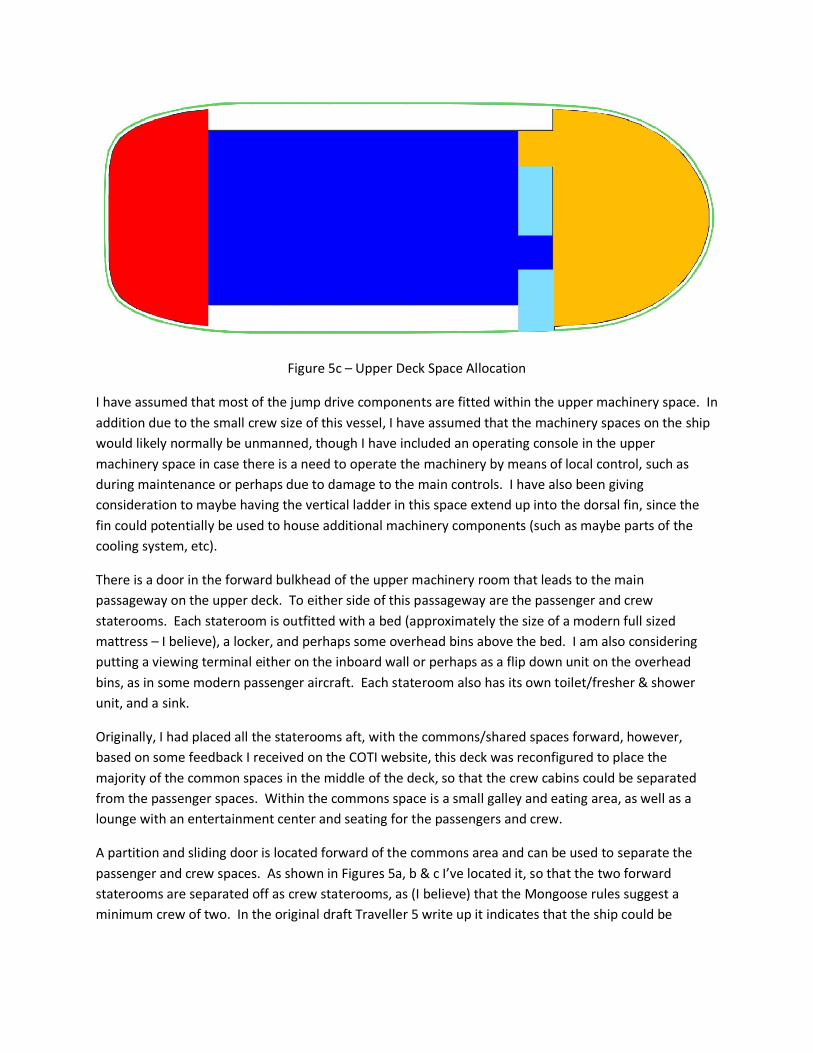
Figure 5c – Upper Deck Space Allocation
I have assumed that most of the jump drive components are fitted within the upper machinery space. In
addition due to the small crew size of this vessel, I have assumed that the machinery spaces on the ship
would likely normally be unmanned, though I have included an operating console in the upper
machinery space in case there is a need to operate the machinery by means of local control, such as
during maintenance or perhaps due to damage to the main controls. I have also been giving
consideration to maybe having the vertical ladder in this space extend up into the dorsal fin, since the
fin could potentially be used to house additional machinery components (such as maybe parts of the
cooling system, etc).
There is a door in the forward bulkhead of the upper machinery room that leads to the main
passageway on the upper deck. To either side of this passageway are the passenger and crew
staterooms. Each stateroom is outfitted with a bed (approximately the size of a modern full sized
mattress – I believe), a locker, and perhaps some overhead bins above the bed. I am also considering
putting a viewing terminal either on the inboard wall or perhaps as a flip down unit on the overhead
bins, as in some modern passenger aircraft. Each stateroom also has its own toilet/fresher & shower
unit, and a sink.
Originally, I had placed all the staterooms aft, with the commons/shared spaces forward, however,
based on some feedback I received on the COTI website, this deck was reconfigured to place the
majority of the common spaces in the middle of the deck, so that the crew cabins could be separated
from the passenger spaces. Within the commons space is a small galley and eating area, as well as a
lounge with an entertainment center and seating for the passengers and crew.
A partition and sliding door is located forward of the commons area and can be used to separate the
passenger and crew spaces. As shown in Figures 5a, b & c I’ve located it, so that the two forward
staterooms are separated off as crew staterooms, as (I believe) that the Mongoose rules suggest a
minimum crew of two. In the original draft Traveller 5 write up it indicates that the ship could be

operated by only one crew, and if that is the case, the partition and door could be relocated forward
one square to place the starboard side forward stateroom aft of the partition.
A small laundry is located forward of the staterooms on the starboard side. For the most part, I
assumed that the passengers wouldn’t be onboard that long & as such probably wouldn’t need to use a
laundry, but that the crew may have more need of one. Forward of the laundry is the main stairwell
down and a proper airlock. In space, or on vacuum worlds, or worlds with a hazardous atmosphere this
airlock would be the primary means on entrance and egress from the ship.
At the forward most end of the upper deck is the bridge. Within this space are the main ship controls,
space for three ½ dton equipment racks, a server room for the ship’s computer systems (which may also
house stuff like uninterruptible power supplies (UPS) etc for the computers), a ship’s locker/safe, a deck
head, and a small coffee nook/break area.
In general I have assumed that the outer shell of the ship is supported by ring frame stiffeners about
200mm (8in) deep and longitudinal girders, in way of the main bulkheads and decks, etc. As was shown
in Figure 3, I have assumed that the height of the upper deck is about 2.3m clear height plus some
structure above, except at the outboard edge, where the deck height slopes down. Based on feedback
from the COTI website, it was suggested that I could instead reconfigure the upper deck to make the
ceiling outboard follow the shape of the hull (with and offset for the framing) which would allow for a
higher open height in the staterooms, as shown in Figure 6. This seems like it might not be a bad idea,
and you could assume that this is how the ship is configured without any real change to the deck plans,
but for now I have assumed that the decks are as shown in Figure 3, since the space above the 2.3m
height can be considered to house life support equipment and such in addition to structure.
Figure 6 – Possible Alternate Cross-section Arrangement

Visualizations:
Having built up a model and laid out the deck plans for the ship, I next wanted to do some 3D
visualizations for the ship. Here I used a program called Vue Esprit. In thinking about this ship, one
thought that crossed my mind was what kind of role it would serve in a Traveller universe. As I
understand it, in basic Traveller canon, vessels like the Scout/Courier and Seeker are the most
predominant 100dton ships while the Free Trader and Far trader are the most predominant small cargo
ships. As such, a Pocket Trader would probably fall somewhere in between all these, perhaps still being
available in large numbers though not being as common as the other types. In some ways this got my
thinking about modern day passenger aircraft, where planes like the Boeing 737 and Airbus A319/320
are amongst the most common aircraft in use, but other planes like the DC-9/MD-80 family of planes
still exist and are in use in fairly large numbers. As such I began to kind of look at the Pocket Trader as
perhaps being like the DC-9/MD-80 is to the 737 and A319/320.
Along these lines, when trying to come up with a color scheme for painting them, I began to think in
terms of how some modern airliners get painted, though I replaced the company name with the ship’s
name. Figure 7 shows a picture of such a paintjob. Initially I named the ship the Venture, because it
conveyed the impression of a voyage or adventure. However, I eventually changed the name to
Venturer, since the possibility for similar names for sister ships seemed greater (such as Wanderer,
Sojourner, Voyager, Transporter, and Traveler, etc). Anyway, Figures 8 & 9 show some images of the
ship I have developed in some different paintjobs based on these thoughts. I’m still learning Vue Esprit,
and hopefully over time I’ll be able to improve on these images. I also hope to eventually maybe also
develop up some internal views as well.
Right now, I have not shown any windows along the side of the craft, but I have been considering added
some. The thought would be that there would be a small window in each stateroom and also in the
common spaces, along the upper deck. They would cut a little into the fuel tankage outboard of these
spaces, but I don’t think the impact would be major. Hopefully, I’ll try and update the images later, to
show these viewports. I also am considering some revisions to the layout of the bridge as well, though
the I think that the current one should be reasonably functional.
Additionally, I currently don’t show a turret fitted, but I may try and revise that later as well.
While doing the deck plans, one thing that kind of struck me was how the upper deck looked kind of like
some of the sushi I had for lunch that day. As such I also did up one paintjob for a ship as kind of a
salmon nigiri roll, as shown in Figure 10. A jet black colored “Stealthy Intruder” is also shown in Figure
11.

Figure 7 – SS Venturer
Figure 8 – SS Wanderer

Figure 9 – SS Traveler
Figure 10 – SS Nigiri

Figure 11 – A Stealthy Intruder
Other Options:
Executive Transport
While putting this stuff together I noticed that in some ways the ship looks a little like a van which got
me thinking about possible conversion options. Since I had been looking at the ship kind of along the
lines of a passenger aircraft, I began to think about making an option like a private jet (maybe like the
Beoing Business Jet).
Figure 12 shows an image of the lower deck of the vessel outfitted as an executive transport. It includes
a large suite, with a king size bed and full bath, plus a smaller suite with a standard bed and bath. It also
includes a small conference room/dining area, a vehicle bay, and a reduced cargo space (including space
recovered from the low berth, which have been removed.

Figure 12 – Executive Transporter Lower Deck
I’m not fully sure how to spec this out in Traveller terms but I thought it is useful for showing some
possibilities for other configurations.
An Alternate Classic Traveller Scout/Courier
During a recent discussion on the COTI Traveller forums, a thread came up discussing alternate deck
plans for Scout/courier Type ships. As part of these discussions I decided to try and use the Pocket
Trader hullform as a basis for some alternate Scout/Courier deck plans. In doing so, I decided to use the
original Classic Traveller rules, in part to see how the hullform would handle the alternate requirements
outlined in those books.
The volume requirements for a Scout/Courier in Classic Traveller are as follows:
Code:
Volume Component Price
(100) Hull-A
20 Bridge and basic controls
1 Computer
10 Jump drive-A (J2)
1 Maneuver drive-A (2G)
4 Power plant-A
40 Fuel
16 Staterooms (4)
1 Fire Control reservation
4 Air/Raft
3 Cargo
------- ------------------------ --------

In order to incorporate the relatively large bridge and basic controls required for this ship, I decided to
retain the 10 dton bridge layout of the Pocket Trader and add an additional 10 dtons devoted to sensor
components and electronics on the deck immediately below the bridge, in lieu of the low berths, fuel
tankage, and forward portion of the cargo hold that would be located there in the Pocket Trader. The
remainder of the cargo hold from the Pocket Trader was then converted to fuel tankage.
On the upper deck I retained the airlock and small laundry, as on the original Pocket Trader, but I
removed two of the staterooms and reconfigured the rest of the space to provide for a small
galley/commons space, four staterooms, a cargo hold and an air/raft bay, as shown in Figures 13 and 14
below. In doing these changes I also relocated and/or removed some doors and bulkhead to suite the
new arrangements.
Figure 13 – Alternate Scout/Courier Deck Plans (Lower Deck)

Figure 14 – Alternate Scout/Courier Deck Plans (Upper Deck)
A larger scale version of Figures 13 and 14 are also included at the end of this document as an appendix.
Regards
PF


Appendix A
Pocket Trader Larger Scale Deck Plans


Appendix B
Scout/Courier Larger Scale Deck Plans

