reverse power relay and protection assemblies rxppk · pdf file ·...
TRANSCRIPT

Reverse power relay and protection assembliesRXPPK 2H and RAPPK
− Two different definite time delay stages. − Trip t1 = 0 - 4 s or Trip t2 = 0 - 30 s − Trip t2 function is supported with a stand by time-hold
function, with the settings 0 or 5 s. When a Start Is has occurred, the t2 timer will not reset until the hold time has expired, regardless if the Start Is has been reset.
− Block functions: – − Undervoltage block: blocking all the functions if the
voltage is less than 40 V − Undercurrent block: blocking all the functions if the cur-
rent is less than 0,25 % of the rated current
Features − Micro-processor based time directional current relay/
protection with continuous settings for operate values and time delays.
− RXPPK 2H is used to detect reverse power or low for-ward power to prevent damage of the prime mover.
− Setting range Ia = 0,3 - 15 % of rated current. − Two variants, with wide setting ranges.
- Scale constant Is = 0,1, 0,4, 0,7, 1,0 A or Is = 0,5, 2,0, 3,5, 5,0 A
(se9
8005
4.ep
s)
(RX
PP
K_2
H.t
if)
2 1MRK 509 042-BEN Revision: B | Reverse power relay and protection assemblies
Application
The purpose of the reverse power relay is basically to prevent damage of the prime mover (turbine or motor) upon a reverse power condition. If the driving torque becomes less than the total losses in the generator and the prime mover, the gen-erator starts to work as a synchronous compensator, taking necessary active power from the network.
In case of steam turbines, a reduction of the steam flow re-duces the cooling effect of the turbines blades and overheat-ing may occur. Hydro turbines of the Kaplan type and bulb type may also be damaged due to the fact that the turbine blade surf on the water and set up an axial pressure on the bearing. Diesel engines may be damaged due to insufficient lubrication.
one percent of rated value, low forward power principle (see Fig. 2)
The time step t1 is mainly arranged to trip the field and the generator breaker with a short time delay, typically 2 - 3 sec-onds after operation of the reverse power measuring function.
The reverse power function with time step t1 can be used in the normal decommissioning routine to avoid excessive overspeeding when taking steam powered generators off ser-vice. The function can also be used to interlock the generator breaker tripping for non-urgent faults.
The purpose of the second stage is to prevent excessively high temperature and possible mechanical damage to the prime mover. The time delay can be longer in this case, typi-cally 10 - 15 seconds. A reset delay, of 5 seconds can be activated to ensure operation, even if power swing makes the current function pick up and reset during the measuring period.
A rather common arrangement in older power plants is the use of V-connected voltage transformers. The VT’s then have no neutral point available. Polarizing voltage to a RXPPK 2H relay, measuring the current in L1, can be arranged with two 2200 W, 2 W resistors shown in Figure 1. E.g. two RTXE can
Type Total loss
Steam turbine 1 - 3%
Hydraulic turbine 1 - 3%
Gas turbine 5%
Diesel engine 25%
The total losses at rated speed, as a percentage of the rated power of the generator, areapproximately:
L3 L2VM
L1
VL1-VM
(98000028)
R R
Figure 1: Voltage VL1 - VM is obtained using resistors for polarizing RXPPK 2H when measuring current in L1. The figure shows Vconnec-ted voltage transformers connected between L1 and L2 and L3 and L1 respectively.
be used, each with 2200 W, ordering number RK 741 225-DG.
The difference in resistance value between the two resistors should be kept as low as 10 ohms in order not to introduce appreciable angular errors if the operate value of RXPPK 2H is set to 1% of rated generator current or lower.
These table values apply to the case when the power input to the prime mover is completely cut off. Thus, in the case when the total power losses of a unit are covered partly by the prime mover and partly by electrical power from the system, the actual power drawn by a generator, during certain motor-ing conditions, may be much less than the above percentage values.
The generator currents remains balanced when the machine is working as a motor, hence, a single-pole relay is fully sufficient if the sensitivity is high. For large turbo units, an additional relay may be connected to a different phase in order to obtain redundancy.
When the generator is working as a motor, the small active current to the machine may be combined with a substantial reactive current delivered by the machine. Hence, the angu-lar error of voltage and current transformers feeding low set reverse power relays should be small.
For large turbo-generators, where the reverse power may be substantially less than one percent, reverse power protection is obtained by a minimum power relay, which normally is set to trip the machine when the active power output is less than
(980
0002
8.p
df)

1MRK 509 042-BEN Revision: B | Reverse power relay and protection assemblies | 3
Design
The reverse power relay protection assemblies with RXPPK 2H can be delivered with different output circuits.
The RXPPK 2H relay requires a separate dcdc converter for auxiliary supply (±24 V). One RXTUG converter can supply up to nine relays.
Note: Before the RXPPK 2H relay or the dcdc converter RX-TUG is plugged into or withdrawn from a terminal base, the auxiliary voltage supply must be interrupted. It is not allowed to disconnect the wiring on the plus or minus supply with the unit in service, since this may result in an unwanted relay operation.
RXPPK 2H measuring relay RXPPK 2H is a microprocessor based relay with one measu-ring stage and two different definite time delay stages. The relay has two input transformers for current and voltages, filter circuits, HMI, LEDs for start, trip indications and three output units which provide separate change-over contacts for start and trip functions. The relay has also two binary inputs, one for reset of LED’s and the other to block or enable the trip t1 function.
Operate values are set with the potentiometers and program-ming switches. Both time delay stages can independently be programmed for the different times.
The start function output is energized immediately after the measured value exceeds or falls below the set start level, depending on setting for reverse (over) power or low forward (under) power operation.
4 1MRK 509 042-BEN Revision: B | Reverse power relay and protection assemblies
Technical data
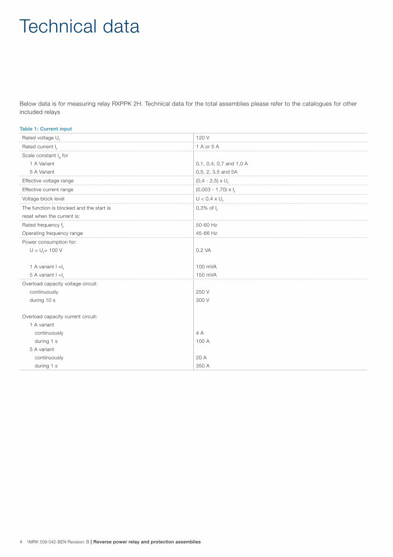
Below data is for measuring relay RXPPK 2H. Technical data for the total assemblies please refer to the catalogues for other included relays
Table 1: Current input
Rated voltage Ur 120 V
Rated current Ir 1 A or 5 A
Scale constant Is for
1 A Variant
5 A Variant
0,1, 0,4, 0,7 and 1,0 A
0,5, 2, 3,5 and 5A
Effective voltage range (0,4 - 2,5) x Ur
Effective current range (0,003 - 1,70) x Ir
Voltage block level U < 0,4 x Ur
The function is blocked and the start is
reset when the current is:
0,3% of Ir
Rated frequency frOperating frequency range
50-60 Hz
45-66 Hz
Power consumption for:
U = Ur= 100 V
1 A variant I =Ir 5 A variant I =Ir
0,2 VA
100 mVA
150 mVA
Overload capacity voltage circuit:
continuously
during 10 s
Overload capacity current circuit:
1 A variant
continuously
during 1 s
5 A variant
continuously
during 1 s
250 V
300 V
4 A
100 A
20 A
350 A

1MRK 509 042-BEN Revision: B | Reverse power relay and protection assemblies | 5
Table 3: Time functions
Time function Trip t1 Trip t2
Time delay Definite time
Setting range 0 - 4 s 0 - 30 s
Accuracy 1% and ±20 ms
Reset delay, th (for function at power swing) – 0 - 5 s
Table 2: Power functions
Function Power functions Ia> / Ia<
Function characteristic selectable in the front between:
Ia>: Reverse power function
Ia<: Low forward power function
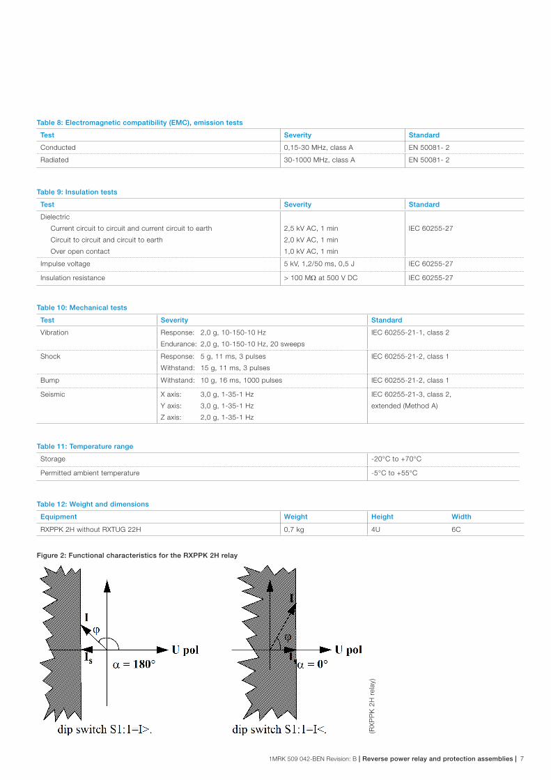
I x cos(j-b-a) ≥ set Ia> see Fig. 2 (a = 180°)
I x cos(j-b-a) ≤ set Ia<(a = 0°)
Setting range Ia 0,3 - 15% of IrSetting range b
(adjustment for correction of system angle inaccuracy)
±3°
Consistency of set operate value <5% for current <0,02 x Ir<2% for current >0,02 x Ir
Phase angle j consistency <0,5°
Angle j between U and I Positive if I lags U
Typical operate time I = 0 => 2 x set operate value 100 ms
Typical reset time I = 2 => 0 x set operate value 100 ms
Typical reset ratio 80%
Frequency dependence within frequency
±5% of rated frequency
±10% of rated frequency
<0,8°
<1,5°
Temperature dependence within range -5°C to +55°C <0,5°
Binary input 1, selectable in the front between:
Block
Enable
Active signal blocking Trip t1 function
Active signal enables Trip t1 function
Table 4: Auxiliary DC voltage supply
Auxiliary voltage EL for RXTUG 22H
Auxiliary voltage for the relay
24 - 250 V DC, ±20%
±24 V (from RXTUG 22H)
Power consumption at RXTUG 22H input
24-250 V
before operation
after operation
without RXTUG 22H
±24 V
before operation
after operation
max. 5,5 W
max. 6,5 W
max. 3,0 W
max. 4,0 W
6 1MRK 509 042-BEN Revision: B | Reverse power relay and protection assemblies
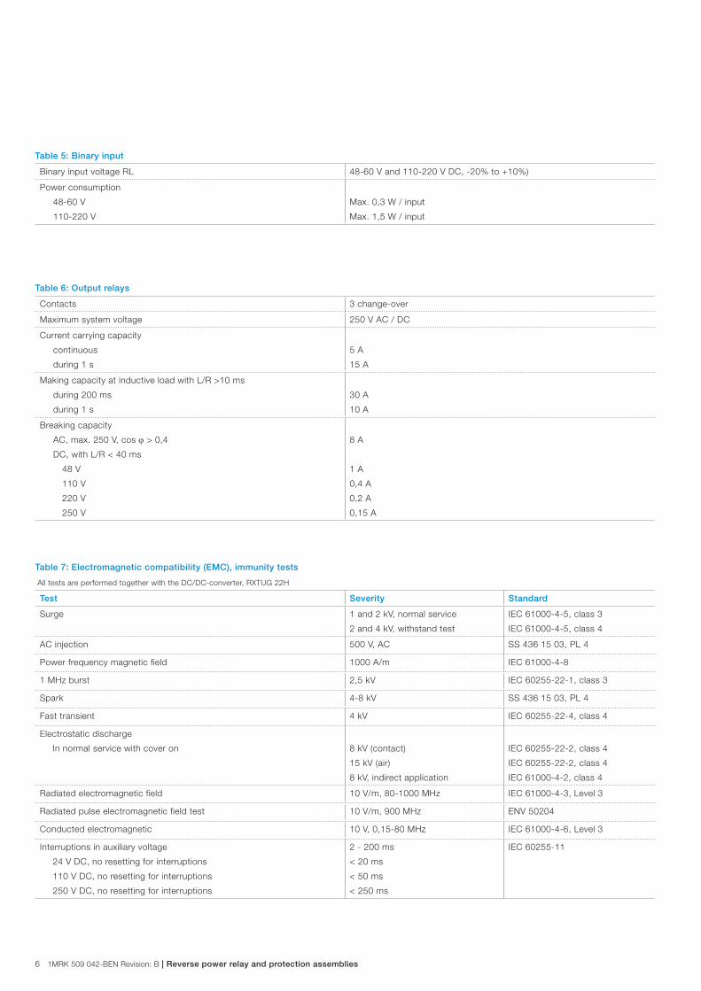
Table 5: Binary input
Binary input voltage RL 48-60 V and 110-220 V DC, -20% to +10%)
Power consumption
48-60 V
110-220 V
Max. 0,3 W / input
Max. 1,5 W / input
Table 6: Output relays
Contacts 3 change-over
Maximum system voltage 250 V AC / DC
Current carrying capacity
continuous
during 1 s
5 A
15 A
Making capacity at inductive load with L/R >10 ms
during 200 ms
during 1 s
30 A
10 A
Breaking capacity
AC, max. 250 V, cos j > 0,4
DC, with L/R < 40 ms
48 V
110 V
220 V
250 V
8 A
1 A
0,4 A
0,2 A
0,15 A
Table 7: Electromagnetic compatibility (EMC), immunity tests
All tests are performed together with the DC/DC-converter, RXTUG 22H
Test Severity Standard
Surge 1 and 2 kV, normal service
2 and 4 kV, withstand test
IEC 61000-4-5, class 3
IEC 61000-4-5, class 4
AC injection 500 V, AC SS 436 15 03, PL 4
Power frequency magnetic field 1000 A/m IEC 61000-4-8
1 MHz burst 2,5 kV IEC 60255-22-1, class 3
Spark 4-8 kV SS 436 15 03, PL 4
Fast transient 4 kV IEC 60255-22-4, class 4
Electrostatic discharge
In normal service with cover on 8 kV (contact)
15 kV (air)
8 kV, indirect application
IEC 60255-22-2, class 4
IEC 60255-22-2, class 4
IEC 61000-4-2, class 4
Radiated electromagnetic field 10 V/m, 80-1000 MHz IEC 61000-4-3, Level 3
Radiated pulse electromagnetic field test 10 V/m, 900 MHz ENV 50204
Conducted electromagnetic 10 V, 0,15-80 MHz IEC 61000-4-6, Level 3
Interruptions in auxiliary voltage
24 V DC, no resetting for interruptions
110 V DC, no resetting for interruptions
250 V DC, no resetting for interruptions
2 - 200 ms
< 20 ms
< 50 ms
< 250 ms
IEC 60255-11
1MRK 509 042-BEN Revision: B | Reverse power relay and protection assemblies | 7
Table 8: Electromagnetic compatibility (EMC), emission tests
Test Severity Standard
Conducted 0,15-30 MHz, class A EN 50081- 2
Radiated 30-1000 MHz, class A EN 50081- 2
Table 9: Insulation tests
Test Severity Standard
Dielectric
Current circuit to circuit and current circuit to earth
Circuit to circuit and circuit to earth
Over open contact
2,5 kV AC, 1 min
2,0 kV AC, 1 min
1,0 kV AC, 1 min
IEC 60255-27
Impulse voltage 5 kV, 1,2/50 ms, 0,5 J IEC 60255-27
Insulation resistance > 100 MW at 500 V DC IEC 60255-27
Table 10: Mechanical tests
Test Severity Standard
Vibration Response: 2,0 g, 10-150-10 Hz
Endurance: 2,0 g, 10-150-10 Hz, 20 sweeps
IEC 60255-21-1, class 2
Shock Response: 5 g, 11 ms, 3 pulses
Withstand: 15 g, 11 ms, 3 pulses
IEC 60255-21-2, class 1
Bump Withstand: 10 g, 16 ms, 1000 pulses IEC 60255-21-2, class 1
Seismic X axis: 3,0 g, 1-35-1 Hz
Y axis: 3,0 g, 1-35-1 Hz
Z axis: 2,0 g, 1-35-1 Hz
IEC 60255-21-3, class 2,
extended (Method A)
Table 11: Temperature range
Storage -20°C to +70°C
Permitted ambient temperature -5°C to +55°C
Table 12: Weight and dimensions
Equipment Weight Height Width
RXPPK 2H without RXTUG 22H 0,7 kg 4U 6C
Figure 2: Functional characteristics for the RXPPK 2H relay
(RX
PP
K 2
H r
elay
)

8 1MRK 509 042-BEN Revision: B | Reverse power relay and protection assemblies
Diagrams
Figure 3: Terminal diagram RXPPK 2H
0 V+24V -24V
48...60V 112
326 327328
316 317
318
313
315314
0V 113
114 115
RL
Ia
Ia
Ia
110...220V 111
122 48...60V
123
324
325
331
341
117116
0V
0V
120V
Ir
0A
RL
Ur
Ir
121 110...220V
BIN 1 BIN 2
t1
t2
Figure 4: Terminal diagram 1MRK 001 058-EAA
(980
0002
5.ep
s)
(1M
RK
0010
58-E
AA
.ep
s)
1MRK 509 042-BEN Revision: B | Reverse power relay and protection assemblies | 9
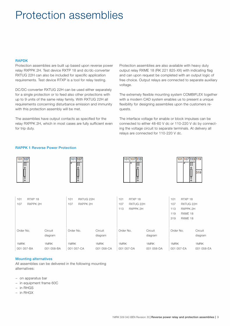
RAPPK 1 Reverse Power Protection
RAPDK Protection assemblies are built up based upon reverse power relay RXPPK 2H. Test device RXTP 18 and dc/dc-converter RXTUG 22H can also be included for specific application requirements. Test device RTXP is a tool for relay testing.
DC/DC-converter RXTUG 22H can be used either separately for a single protection or to feed also other protections with up to 9 units of the same relay family. With RXTUG 22H all requirements concerning disturbance emission and immunity with this protection assembly will be met.
The assemblies have output contacts as specified for the relay RXPPK 2H, which in most cases are fully sufficient even for trip duty.
Protection assemblies are also available with heavy duty output relay RXME 18 (RK 221 825-XX) with indicating flag and can upon request be completed with an output logic of free choice. Output relays are connected to separate auxiliary voltage.
The extremely flexible mounting system COMBIFLEX together with a modern CAD system enables us to present a unique flexibility for designing assemblies upon the customers re-quests.
The interface voltage for enable or block impulses can be connected to either 48-60 V dc or 110-220 V dc by connect-ing the voltage circuit to separate terminals. At delivery all relays are connected for 110-220 V dc.
Protection assemblies
101 RTXP 18
107 RXPPK 2H
101 RXTUG 22H
107 RXPPK 2H
101 RTXP 18
107 RXTUG 22H
113 RXPPK 2H
101 RTXP 18
107 RXTUG 22H
113 RXPPK 2H
119 RXME 18
319 RXME 18
Order No. Circuit
diagram
Order No. Circuit
diagram
Order No. Circuit
diagram
Order No. Circuit
diagram
1MRK
001 057-BA
1MRK
001 058-BA
1MRK
001 057-CA
1MRK
001 058-CA
1MRK
001 057-DA
1MRK
001 058-DA
1MRK
001 057-EA
1MRK
001 058-EA
Mounting alternativesAll assemblies can be delivered in the following mounting alternatives:
− on apparatus bar − in equipment frame 60C − in RHGS − in RHGX

10 1MRK 509 042-BEN Revision: B | Reverse power relay and protection assemblies
Ordering
Specify RAPPK(Protection):
− Quantity − Ordering number − Code A, H, M − Desired wording on the lower half of the test switch face
plate max. 13 lines with 14 characters per line
Specify RXPPK (Loose Relay): − Quantity − Ordering number
Reverse Power RelayType Voltage Frequency Article No. Code
RXPPK 2H 1 A 50 Hz 1MRK 001 615-AA A1
RXPPK 2H 5 A 50 Hz 1MRK 001 615-BA A3
RXPPK 2H 1 A 60 Hz 1MRK 001 615-CA A2
RXPPK 2H 5 A 60 Hz 1MRK 001 615-DA A4
MountingMounting alternatives Size Article No. Code
Apparatus bars M10
Equipment frame without door 4U 19” 1MRK 000 137-GA M11
Equipment frame with door 4U 19” 1MRK 000 137-KA M12
RHGX 4 4U 12C RK 927 001-AB M71
RHGX 8 4U 24C RK 927 002-AB M72
RHGX 12 4U 36C RK 927 003-AB M73
RHGX 20 4U 60C RK 927 004-AB M74
RHGS 30 6U x 1/1 19” rack 1MRK 000 315-A M81
RHGS 12 6U x 1/2 19” rack 1MRK 000 315-B M82
RHGS 6 6U x 1/4 19” rack 1MRK 000 315-C M83
Auxiliary voltageFor included auxiliary relays Code
24 V DC H5
48-55 V DC H6
110-125 V DC H7
220-250 V DC H8

1MRK 509 042-BEN Revision: B | Reverse power relay and protection assemblies | 11
References
Connection and installation components inCOMBIFLEX 1MRK 513 003-BENRelay accessories COMBIFLEX 1MRK 513 004-BENUser’s Guide RXPPK 2H 1MRK 509 042-UEN

12 1MRK 509 042-BEN Revision: B | Reverse power relay and protection assemblies
For more information please contact: ABB AB Substation Automation Products721 59 Västerås, Sweden Phone: +46 (0) 21 32 50 00
www.abb.com/protection-control
ABB India Limited Plot no. 4A, 5 & 6, II PhasePeenya Industrial AreaBangalore - 560 058. India Phone: +91 80 2294 9632Facsimile: + 91 80 2294 9188
Note:We reserve the right to make technical changes or modify the contents of this document without prior notice. ABB AB does not accept any responsibility whatsoever for potential errors or possible lack of information in this document.We reserve all rights in this document and in the subject matter and illustrations contained herein. Any reproduction, disclosure to third parties or utilization of its contents – in whole or in part – is forbidden without prior written consent of ABB AB.
© Copyright 2013 ABB.
All rights reserved.