reverse software engineering large object oriented software
TRANSCRIPT

Reverse Software Engineer ing
Large Object Or iented Software Systems
using the UML Notation
Surendranath Ramasubbu
Thesis submitted to the faculty of the
Virginia Polytechnic Institute and State University
in partial fulfillment of the requirements for the degree of
Master of Science
in
Electrical Engineering
Dr. Pushkin Kachroo, Chair
Dr. Lynn Abbott
Dr. Binoy Ravindran
Mr. Mark W Vinson
April 26, 2001
Blacksburg, Virginia
Keywords: Reverse Engineering, Unified Modeling Language, Design Recovery,Program Comprehension, Re-engineering, Software Engineering
Copyright 2000, Surendranath Ramasubbu
Reverse Software Engineer ing Large Object Or iented Software Systems
using the UML Notation
Surendranath Ramasubbu
ABSTRACT
A common problem experienced by the software engineering community traditionally
has been that of understanding legacy code. A decade ago, legacy code was used to refer
to programs written in COBOL, typically for large mainframe systems. However, current
software developers predominantly use Object Oriented languages like C++ and Java.
The belief prevalent among software developers and object philosophers that
comprehending object-oriented software will be relatively easier has turned out to be a
myth. Tomorrow’s legacy code is being written today, since object oriented programs are
even more complex and difficult to comprehend, unless rigorously documented. Reverse
Engineering is a methodology that greatly reduces the time, effort and complexity
involved in solving the program comprehension problem.
This thesis deals with Reverse Engineering complex object oriented software and the
experiences with a sample case study. Extensive survey of literature and contemporary
research on reverse engineering and program comprehension was undertaken as part of
this thesis work. An Energy Information System (EIS) application created by a leading
energy service provider and one that is being used extensively in the real world was
chosen as a case study. Reverse engineering this industry strength Java application
necessitated the definition of a formal process. An intuitive Reverse Engineering Process
(REP) was defined and used for the reverse engineering effort. The learning experiences
gained from this case study are discussed in this thesis.

Acknowledgements
It would be fitting to thank my advisor, Dr Pushkin Kachroo at the outset, who besides
providing constant support and encouragement for completing my thesis work, also
placed immense faith in my abilities and gave me enough freedom and space to explore
and research.
Special thanks to Dr Lynn Abbott and Dr Binoy Ravindran for having spared time and
effort in supporting my Graduate course work as also for this thesis.
My list of people to thank would be incomplete without acknowledging the contribution
of Mr. Mark Vinson, at AEP Communications towards the work that formed the
backbone of this thesis. His words of encouragement and interest and a penchant for the
“Big Picture” kept me motivated at times when the going was tough. Along with him I
thank all the folks at AEPC, Roanoke for their support and for sitting through my
lectures!
Most of all, many thanks to my wife Anitha, who patiently endured long lonely hours,
and to my family for making me everything I am.

iv
Contents
Chapter 1: Introduction--------------------------------------------------------------------------- 1
1.1 Motivation-------------------------------------------------------------------------- 2
1.2 Reverse Engineering and Object Orientation --------------------------------- 3
1.3 Case Study: Reverse Engineering the EIS Client application -------------- 3
1.3.1 History of the EIS Client ------------------------------------------------- 4
1.3.2 Initial Status of the EIS Client ------------------------------------------- 4
1.4 Contribution------------------------------------------------------------------------ 5
Chapter 2: The State of the Ar t in Reverse Engineer ing----------------------------------- 6
2.1 Early work in Reverse Engineering -------------------------------------------- 7
2.1 A Taxonomy ----------------------------------------------------------------------- 8
2.3 Difficulties in Reverse Engineering -------------------------------------------- 9
2.4 Different Approaches to Reverse Engineering------------------------------- 10
2.4.1 Program Comprehension Approach ------------------------------------ 11
2.4.2 Extracting Design Patterns----------------------------------------------- 12
2.4.3 Knowledge based Approach--------------------------------------------- 13
2.4.4 Domain Analysis Approach---------------------------------------------- 16
2.4.5 Program Slicing Approach----------------------------------------------- 17
2.4.6 Other Automated Approaches------------------------------------------- 19
2.5 Survey of Tools and Benchmarks---------------------------------------------- 20
2.6 The Case for Modeling during Development -------------------------------- 21

Contents v
2.7 Survey of similar and related work -------------------------------------------- 23
Chapter 3: A br ief introduction to the UML ------------------------------------------------ 26
3.1 The Need for a Modeling Language------------------------------------------- 27
3.2 History of the UML -------------------------------------------------------------- 27
3.3 Evolution of the UML ----------------------------------------------------------- 28
3.4 Goals of the UML ---------------------------------------------------------------- 28
3.5 Modeling using UML – an Overview ----------------------------------------- 29
3.5.1 The Need for Modeling--------------------------------------------------- 29
3.5.2 Principle of Modeling using UML -------------------------------------- 30
3.5.3 UML – the Language----------------------------------------------------- 31
3.6 The UML Notation – an Overview -------------------------------------------- 33
3.6.1 Things in the UML ------------------------------------------------------- 34
3.6.1.1 Structural Things in the UML --------------------------------- 34
3.6.1.2 Behavioral Things in the UML -------------------------------- 36
3.6.1.3 Grouping Things in the UML---------------------------------- 37
3.6.1.4 Annotational Things in the UML------------------------------ 37
3.6.2 Relationships in the UML ----------------------------------------------- 38
3.6.3 Diagrams in the UML---------------------------------------------------- 40
3.6.3.1 Class Diagram---------------------------------------------------- 40
3.6.3.2 Package/Component Diagram--------------------------------- 41
3.6.3.3 Use Case Diagram----------------------------------------------- 42
3.6.3.4 Interaction Diagram - Sequence------------------------------- 43
3.6.3.5 Interaction Diagrams - Collaboration------------------------- 44
3.6.3.6 Activity Diagram ------------------------------------------------ 45
3.6.3.7 State Diagram ---------------------------------------------------- 46
3.7 Comments------------------------------------------------------------------------- 47
Chapter 4: Preliminary work before Reverse Engineer ing------------------------------- 48
4.1 Generic Ideas--------------------------------------------------------------------- 49
4.1.1 Collect the Various Artifacts-------------------------------------------- 49

Contents vi
4.1.2 Develop Functional Experience ---------------------------------------- 49
4.1.3 Establish Control over building the software system---------------- 49
4.1.4 Evaluate Tools for Reverse Engineering------------------------------ 50
4.1.5 Select the Visual Modeling Medium----------------------------------- 50
4.1.6 Build the Architectural Models of the System ----------------------- 50
4.1.7 Adapt to a Suitable Development Environment---------------------- 51
4.1.1 Debug the Software in the Development Environment ------------- 51
4.2 Case Study Experience --------------------------------------------------------- 52
4.2.1 Collection of Artifacts --------------------------------------------------- 52
4.2.2 Functional Experience --------------------------------------------------- 52
4.2.3 Control over building the software------------------------------------- 52
4.2.4 Tools for Reverse Engineering ----------------------------------------- 52
4.2.5 Choice of the Visual Modeling Medium------------------------------ 53
4.2.6 Architectural Models of the System ----------------------------------- 53
4.2.7 Adaptation to a Suitable Development Environment---------------- 53
Chapter 5: Reverse Engineer ing Process: a Case Study ---------------------------------- 54
5.1 Introduction and Motivation---------------------------------------------------- 55
5.2 Related Work --------------------------------------------------------------------- 56
5.3 Abstraction ------------------------------------------------------------------------ 56
5.4 A Reverse Engineering Process (REP)---------------------------------------- 59
5.4.1 Definition of Goals of RE ----------------------------------------------- 59
5.4.2 Development of a Feature Description -------------------------------- 60
5.4.3 Extraction of Source Model --------------------------------------------- 60
5.4.4 Abstraction of Architectural Model ------------------------------------ 61
5.4.5 Consolidation-------------------------------------------------------------- 62
5.4.6 Utilization------------------------------------------------------------------ 63
5.5 Case Study – the EIS Client Application ------------------------------------- 64
5.5.1 Definition of Goals------------------------------------------------------- 64
5.5.2 Feature Description------------------------------------------------------- 65
5.5.2.1 Use Case Diagram example – top level ---------------------- 66

Contents vii
5.5.2.2 Use Case Diagram example – fine grained ------------------ 72
5.5.2.3 Activity Diagram for a Use Case------------------------------ 73
5.5.3 Extraction of Source Model --------------------------------------------- 75
5.5.3.1 Class Diagram example----------------------------------------- 76
5.5.3.2 Interaction Diagrams example--------------------------------- 78
5.5.4 Abstraction of the Architectural Model ------------------------------- 80
5.5.5 Consolidation-------------------------------------------------------------- 81
5.5.6 Utilization------------------------------------------------------------------ 81
5.6 Lessons Learned------------------------------------------------------------------ 82
Conclusion and Future Work ------------------------------------------------------------------- 83
Bibliography ---------------------------------------------------------------------------------------- 85
Vita---------------------------------------------------------------------------------------------------- 89

viii
List of Figures
3.1 Class Notation in UML----------------------------------------------------------------------- 34
3.2 Interface Notation in UML ------------------------------------------------------------------ 35
3.3 Collaboration Notation in UML ------------------------------------------------------------ 35
3.4 Use Case Notation in UML------------------------------------------------------------------ 35
3.5 Component Notation in UML --------------------------------------------------------------- 36
3.6 Node Notation in UML----------------------------------------------------------------------- 36
3.7 Interaction Notation in UML ---------------------------------------------------------------- 36
3.8 State Notation in UML ----------------------------------------------------------------------- 37
3.9 Grouping Notation in UML------------------------------------------------------------------ 37
3.10 Annotation Notation in UML --------------------------------------------------------------- 37
3.11 Dependency Notation in UML -------------------------------------------------------------- 38
3.12 Association Notation in UML--------------------------------------------------------------- 38
3.13 Aggregation Notation in UML -------------------------------------------------------------- 39
3.14 Generalization Notation in UML ----------------------------------------------------------- 39
3.15 A typical UML Class Diagram-------------------------------------------------------------- 40
3.16 A typical UML Package Diagram ---------------------------------------------------------- 41
3.17 A typical UML Use Case Diagram--------------------------------------------------------- 42
3.18 A typical UML Sequence Diagram--------------------------------------------------------- 43

List of Figures ix
3.19 A typical UML Collaboration Diagram---------------------------------------------------- 44
3.20 A typical UML Activity Diagram ---------------------------------------------------------- 45
3.21 A typical UML State Diagram -------------------------------------------------------------- 46
5.1 Levels of Abstraction------------------------------------------------------------------------- 58
5.2 The REP phases------------------------------------------------------------------------------- 63
5.3 Use Case Diagram for the EIS Client ------------------------------------------------------ 66
5.4 Fine grained Use Case Diagram ------------------------------------------------------------ 72
5.5 Activity Description for the EIS Client Begins Use Case------------------------------- 74
5.6 Example Class Diagram showing classes that implement EIS Client Start-up ------ 77
5.7 Sequence Diagram that Describes the Application Start-up---------------------------- 78
5.8 Collaboration Diagram that Describes the Application Start-up----------------------- 78
5.9 Architectural Description of the Application --------------------------------------------- 80

1
Chapter 1
Introduction
The primary product of a development team is not beautiful documents, world-class meetings, great slogans, or Pulitzer-prize-winning lines of source code.Rather it is good software that satisfies the evolving needs of its users and thebusiness. Everything else is secondary.
Booch, Rumbaugh and Jacobson
2
1 Introduction
1.1 Motivation
A common problem experienced by the software engineering community traditionally
has been that of understanding legacy code. Legacy code is a semi-formal term that refers
to the programs coded for typically industry strength projects, which become increasingly
difficult to understand as they grow in size and complexity.
Software engineering has undergone a paradigm shift as the size of the software systems
deployed increased dramatically and businesses began to rely increasingly on computers
and information systems. A substantial portion of the software development effort is
spent on maintaining existing systems rather than developing new ones [2]. An estimated
50% to 80% of the time and material involved in software development is devoted to
maintenance of existing code [15]. Crucial to the maintenance of existing systems is the
task of program comprehension, an emerging area in software engineering. 47% of the
time spent on enhancements to existing programs and 62% of that spent on program
corrections involve program comprehension tasks like reading the documentation,
scanning the source code, and understanding the changes to be made [16].
A decade ago, legacy code was used to refer to programs written in COBOL, typically for
large mainframe systems. However, today’s software developers predominantly use
Object Oriented languages like C++ and Java. This means that tomorrow’s legacy code is
being written today, since object oriented programs are even more complex and difficult
to comprehend, unless rigorously documented. Unless this kind of revolution sweeps the

Chapter 1. Introduction 3
software industry, we are going to end up with software that is even more obscure
accompanied by insufficient design documentation.
Reverse Engineering is a methodology that greatly reduces the time, effort and
complexity involved in solving the program comprehension problem. Reverse
Engineering is best defined by Chikofsky and Cross [1] as “ the process of analyzing a
subject system
• To identify the system’s components and their inter-relationships and
• To create representations of the system in another form or at a higher level of
abstraction.”
1.2 Reverse Engineer ing and Object Or ientation
The belief prevalent among software developers and object philosophers that
comprehending object-oriented software is relatively easier has turned out to be a myth.
Sneed and Donbovari conclude that object oriented programming per se does not increase
maintainability as many would like to believe, but that a constrained and disciplined
object-oriented approach may do so. Software systems built using non-object-oriented
languages like COBOL, FORTRAN, PASCAL and C can be reverse engineered from an
algorithmic perspective. However, large object-oriented programs in C++, Java are
highly fragmented and the reverse engineering effort is extremely difficult [4].
1.3 Case Study: Reverse engineer ing the “ EIS Client” application
This thesis deals with Reverse Engineering in general and the experiences with a sample
case study. An Energy Information System (EIS) application created by a leading energy
service provider (ESP) and one that is being used intensively in the real world was
chosen for the purpose of this project. It includes a portfolio of products and services that
supply information about energy use in order to help customers save time and money. It
consists of several components, the Database, Middle tier, Server Applications and an
EIS Analysis application, as well as other supporting applications and utilities. This thesis

Chapter 1. Introduction 4
adopts the EIS application (heretofore referred to simply as “EIS client” ) at the client side
as a specific real world case for the reverse engineering study. Due to business reasons
coming in the way of disclosure of the intellectual property of the said ESP, and due to
the public nature of this thesis, the names of the EIS application and the ESP would
remain anonymous for the purpose of this thesis document.
1.3.1 History of EIS Client
The EIS client is a heavy industry strength software application that was developed for
the energy service provider by a sub-contractor. After the release and deployment of the
application, the developers were forced to renounce all ties with the EIS client due to
certain operational reasons. Due to the rapidity and scale of the development of the
application, proper documentation of the project in terms of modeling diagrams,
including comments etc. was not done.
In order to encourage research to solve such a prevalent problem, the EIS client
application was turned over to us for the purpose of this thesis to be used as a Case Study
for Reverse Software Engineering. Since this is found to be a typical situation for the
application of Reverse Engineering, the thesis goes into tackling this non-trivial problem
and possible means of solving it. Since the application was written using the Java
programming language in the Object Oriented Programming (OOP) paradigm, the task
was found to be all the more relevant and contemporary.
1.3.2 Initial status of the EIS client
The ESP passed on the knowledge it had gained about the EIS client in the form of the
developer’s documentation and some diagrams during the beginning of this thesis work.
1. The application could not be built from the source files available based on the
Developer’s documentation.
2. Around 600 Java files were in the archive with little documentation on how
they are connected or used.

Chapter 1. Introduction 5
3. A number of third party libraries were used in the project like JClass and DSG
libraries. There was no knowledge on what parts of these libraries were used
and how they were employed.
4. The EIS client could not be built or executed in an Integrated development
environment (IDE).
5. A few static class diagrams were provided for the most complex parts of the
application. However, these diagrams were too complex and not very different
from the complex source code files.
However, the entire system was deployed and the application was, and is, being used by a
growing number of customers across the country. This led to significant problems in
maintenance and customer support for the application due to the scanty knowledge about
the working of the application.
This, therefore, was the state of the application where it was being widely deployed while
there was seemingly little intellectual control on the implementation and source code.
The ESP had inherited a new generation legacy system, which later became the
foundation for this research.
1.4 Contr ibution
A summary of the author’s contributions as a result of this thesis work is shown below.
1. A general, intuitive and formal process for Reverse Engineering Large Scale OO
software has been defined. This process is general at this point and could be extended,
modified or developed to accommodate automated steps.
2. A design artifact (a UML design documentation) has been released to the sponsor as a
result of reverse engineering the case study EIS Client application.

6
Chapter 2
The State of the Ar t
Life can only be understood backwards, but it must be lived forwards.
Soren Kierkegaard

7
2 The State of the Ar t
Considerable work is being done in the area of reverse engineering by various
universities and numerous papers have been published by the IEEE Computer Society
Press - Technical Council on Software Engineering for Reverse Engineering and Re-
engineering besides the proceedings of the IEEE Working Conference on Reverse
Engineering and that on Program Comprehension. Quite a few journal papers have also
been published in this field of work. A glimpse of the literature on reverse engineering,
by no means comprehensive is provided here. Papers that have the most relevance to this
thesis have been chosen and an abstract presented. From a holistic perspective, the papers
have been classified into categories based on the problem domain and the approach
adopted.
2.1 Ear ly Work in Reverse Engineer ing
Reverse Engineering is a well-established practice in that there are numerous CASE tools
available to map source code to good quality structural models. These CASE tools were
being used along side sequential programming languages like COBOL to maintain the
design documentation. However, the concept of Reverse Engineering emerged from the
hardware world where hardware circuits were reverse-engineered to create clones. When
the software engineers adopted the same term to describe some software engineering
practices, there was a dearth of well-defined terminology to use for both technical and
market-place discussions.

Chapter 2. The State of the Ar t 8
2.2 A Taxonomy
It is in the above described context that Chikofsky and Cross [1] made a very successful
attempt at providing some precise and long standing definitions for much of the
terminology used to this day in the field of Reverse Engineering. In this paper, they have
started with a description of the ANSI definition of software maintenance and established
the concept of software development life cycles. Emphasis is placed on the theory that
there exist several higher level abstractions that can be used to describe a subject system
during various stages of the software development life cycle. After defining three specific
abstractions, definitions for Forward Engineering, Reverse Engineering, Restructuring
and Re-engineering are provided.
Reverse Engineering is further classified into Redocumentation and Design Recovery.
Redocumentation is defined as “ the creation or revisions of a semantically equivalent
representation within the same relative abstraction level” , which can then provide easier
ways to visualize relationships among program components. Design Recovery is then
defined as “a subset of Reverse Engineering in which domain knowledge, external
information, and deduction or fuzzy reasoning are added”, to add more meaningful
abstractions than that obtained by examining the system itself.
The objectives of Reverse Engineering are also laid out, the most important of which are
discussed here. The notion of Reverse Engineering is to cope with the complexity of a
software system by building models. These models can be built at different levels of
abstraction, and there could be multiple views of a system. This is analogous to the
different views shown on the blueprint for a building, where no single view is sufficient
to describe the entire system.
The paper concludes with a discussion of the economics of Reverse Engineering. A point
very forcefully made is that even if the reverse engineering effort meets with a limited

Chapter 2. The State of the Ar t 9
level of success, there could be substantial savings in the cost of the software
development and maintenance efforts.
2.3 Difficulties in Reverse Engineer ing
Spencer Rugaber [2] gives an interesting introduction to Reverse Engineering as an
inescapable part of the software development effort. Describing the work done by his
research group at Georgia Tech, the paper introduces Reverse Engineering and begins
with a detailed discussion of the practical difficulties involved in the task. These
difficulties include that of the choice of the level of abstraction needed, and that of the
formal/cognitive distinction. Computers and programming languages are formal, while
the human cognitive capabilities are non-formal. Therefore, the result of any reverse
engineering work could be very subjective. Any program is “understood to the extent that
the reverse engineer can build up correct high level chunks from the low level details
available in the program.”
A discussion of how these difficulties are manifested to the reverse engineer follows. The
choice of methodology, representation and tools used will define the usefulness of the
derived reverse engineering information. The work done on integrating the top-down and
bottom-up approaches to understanding a program to develop an approach, called the
Synchronized Refinement is described. This approach is based on the detection of design
decisions in the source code and the organization of the information into an information
structure suitable for browsing by software maintainers. However, the process suggested
is labor intensive, though the paper suggests that automating the individual tasks in the
process can reduce the rigor involved.
The author suggests that many of the activities described in the Synchronized Refinement
methodology are automatable. He suggests that if a comprehensive information structure
is populated with information about a program, different views of the system can be
extracted from the database as required for understanding a particular part of the source
code.
Chapter 2. The State of the Ar t 10
2.4 Different approaches to Reverse Engineer ing
Reverse Engineering can be attempted at different levels of abstraction. For example, the
executable file could be the subject, the goal being to generate the source code from the
executable. For the purpose of this research, reverse engineering is addressed at the
source code level, building higher levels of abstraction being the objective.
2.4.1 Program Comprehension approach
Erdos and Sneed [3] suggest partial comprehension of complex programs, since huge
legacy programs are “so complex that they cannot be comprehended in their entirety no
matter what forms of representation are used”. The authors contend that maintenance
tasks require the comprehension of a relatively small portion of the program and they
suggest a set of questions, which are answered by an automated tool built by the authors.
The objective of the research is to permit programmers unfamiliar with the purpose and
function of the programs to maintain them at reasonable cost, which has been achieved
with some justifiable assumptions. The approach presented by the authors was developed
while working with maintenance programmers and considering their requests and
requirements.
Instead of a call graph type of diagram to describe the procedures and their interactions
with other procedures in the program, the authors suggest that a Fan-in diagram can be
used along with Low level Data Flow Diagrams. Decision Trees are used to model
complex conditional series of statements. Variables that are referred in multiple locations
in the program are displayed in a window of cross-references. External object references
are also maintained in a separate window. The use of the above tools enables the
programmer to view a set of simple diagram and data windows and comprehend enough
to perform simple maintenance tasks. The authors report a total productivity increase of
30%. A final comparison is made with similar approaches and a conclusion reached that a
partial comprehension approach is the most suitable for any program comprehension
Chapter 2. The State of the Ar t 11
situation where large programs are involved. However the sample programs chosen were
unique in that it was assumed that the users are knowledgeable enough to direct
maintenance requests to particular components, which the maintenance programmer can
use as a starting point for further analysis.
The supposed ease of comprehension of object-oriented programs is squarely denounced
by Sneed and Dombovari [4]. Their paper deals with an ongoing research project that
aims at the difficult task of comprehending complex, distributed, object-oriented software
systems by approaching in a formal disciplined manner. Citing contemporary work in
similar initiatives, the paper goes on to explain that if modeled properly and if supported
by automated tools, even complex, object oriented systems can be comprehended
formally. Most tools suggested in this paper have been implemented and are in operation.
The authors also contend that though the UML is a good choice if a project is well
documented using it, they point out that the person using the design documentation
should be conditioned to think in those terms. Their approach does not use the UML,
since understanding the design gets tied to understanding UML.
A real life case study is examined to estimate the challenge in comprehending a complex
distributed object-oriented system. The C++ front-end of a stockbroker trading system is
considered. This system is more complex than any of the systems considered in previous
research in this area. A dual strategy of top-down and bottom-analysis is adopted. From
the top, one has to start from the existing requirement documentation and trace the
requirements down to the technical implementation artifacts. From the bottom, one has to
start from the existing code and derive technical implementation artifacts, which can be
traced back to the requirements. For this purpose, s set of standard entity definitions and a
tool to extract them with a database to store them in are employed. The goal is a
comprehensive documentation model. Finally the implementation model is linked to the
specification model. This is primarily a problem of association to determine the mapping
between entities in the two models that result from the top-down and bottom-up
approaches respectively. Again, this paper also places emphasis on reverse engineering
required only to the extent of maintaining software like the previous paper discussed.

Chapter 2. The State of the Ar t 12
A similar approach to the one described above was adopted by Mayrhauser and Vans [14]
where only large scale programs were considered, but where cognition was considered
the primary focus area. The paper reports on a software understanding study during
adaptation of large-scale software. The study was designed as an observational field
study of professional maintenance programmers adapting software. The paper details the
design of the study and discusses the results from the programmers. The goal was to
answer several questions about how programmers approach software adaptations, their
work process and their information needs. The programmers were found to work
predominantly at the domain model level, adopting opportunistic and systematic
understanding. A report on the general understanding process, the type of action
programmers performed during the adaptation task, and the level of abstraction at which
they work is included. Though the paper deals with large-scale software, it is more of a
cognitive study about the human element involved in program comprehension.
2.4.2 Extracting Design Patterns
An approach to recover object-oriented design patterns from the design and code is
presented by Antoniol et al. [5]. Design patterns are micro-architectures, high level
building blocks. Design patterns are an emergent technology: they represent well-known
solutions to common design problems in a given context. From the perspective of reverse
engineering the discovery of patterns in software artifacts represents a step in the
program understanding process. A pattern provides knowledge about the role of each
class within the pattern, the reason for certain relationships among pattern constituents
and/or the remaining parts of the system. Design patterns being a relatively young filed,
there are currently few works that address design pattern recovery in the field of program
understanding and design recovery.
A pattern description encompasses its static structure, in terms of classes and objects
participating to the pattern and their relationships, but also behavioral pattern dynamics,
in terms of participants exchanged messages. Five specific design patterns suggested in

Chapter 2. The State of the Ar t 13
previous literature are chosen as samples for recovery. The paper suggests a multi-stage
reduction strategy using software metrics and structural properties to extract structural
design patterns from object-oriented design or code. An intermediate form called the
Abstract Object Language (AOL) is used which is then parsed to get the Abstract Syntax
Tree (AST) from which the software metrics are extracted. Experiments performed on
public domain code and on industrial code have been discussed and the results analyzed.
An average precision of 55% is observed on public domain code, whereas very few
design patterns were detected in industrial code. This is attributed to the observation that
“patterns retrieved from design and code had no intersection” . The tool discussed has
been developed on Java to assure portability across platforms, but at the price of being
quite inefficient.
2.4.3 Knowledge based approach
A knowledge-based approach to achieve program comprehension is evaluated by Abd-El-
Hafiz [17]. The author in this paper evaluates the approach proposed by the same author
in previous publications. It mechanically documents programs by generating first order
predicate logic annotations of their loops. A family of analysis techniques have been
developed and tailored to cover different levels of program complexity. Loop events are
generated and they are verified using a knowledge base of ‘plans’ . The term ‘plan’ is
used to refer to a unit of knowledge required to identify an abstract concept in a program.
The plans in the existing database are used to analyze five different programs. The author
states that this “proves that the knowledge base built by analyzing one program is
generally usable beyond that program.” The knowledge based approach exploits the fact
that there are certain stereotyped programming concepts that are heavily used in
programs and detecting these can be easy using this approach.
A knowledge based loop analysis approach is employed to decompose loops into
fragments, called events. The loop representation is normalized to make it independent of
the programming language. Using the above a knowledge base is built and a chosen set of
programs are used to evaluate the usefulness of the approach. An attempt is made to
Chapter 2. The State of the Ar t 14
prove that the knowledge base built using a specific program can help in understanding
similar stereotyped programming constructs in other programs. In this aspect, detaching
the program construct from the programming language it was written in very useful in
extending the utility of the knowledge base. The author further states that “our approach
can be greatly enhanced by trying to create knowledge bases that are sufficient for
specific application domains” . Future goals include the evaluation of the performance of
this process when used in the above mentioned “application specific domain” based
situations.
Jahnke and Walenstein [18] start from the premise that Reverse Engineering, as such, is a
task that is fraught with imperfections. This is because there are certain simple tasks,
which can be automated during reverse engineering, but there are certain others where a
human element is definitely deemed necessary. Since the task is complex and a holistic
view of the system and the domain are often needed, accounting for imperfect knowledge
is essential. Therefore any realistic characterization of Reverse Engineering should be an
effort to describe it as a joint effort between reverse engineers and supportive computer
tools. This paper evaluates the requirements that a tool should meet to qualify as a
human-centered automation tool for Reverse Engineering. The authors use a prototype
tool called Varlet that is evaluated in an industrial environment. The application being
reverse-engineered is an industrial database. The authors provide a catalogue of
information on the necessity for adopting the imperfect knowledge paradigm in building
reverse-engineering tools. They also mention that though there is no dearth of literature
on the subject, there are not many tools that incorporate the human element into the
reverse-engineering task.
The authors present an argument that “better methods of externally representing,
manipulating and mechanically processing imperfect knowledge must be developed.”
Based on experiences in using a specific tool, the authors extrapolate the conclusions
drawn to other tools used for reverse engineering. A task independent argumentation is
presented to transform the imperfect knowledge and processing from the users into the
tools. Instead of extending the rigor and formality associated with the current reverse

Chapter 2. The State of the Ar t 15
engineering tools, the authors conclude that the tools must be made suitably flexible to
manage the complexity and imperfection associated with the reverse-engineering process.
The paper shows that fully automated tools for reverse engineering would provide precise
artifacts, which will, unfortunately be as useless as the artifacts being reverse-engineered.
Another knowledge based program understanding effort is described by Burnstein and
Saner [10]. A knowledge-based program understanding/fault localization tool called
BUG-DOCTOR is the basis of this research. Stereotypical programming concepts are
represented in a plan library as program plans. The premise for this research is that an
exhaustive search through such a plan library to identify a plan for the target code can be
computationally very inefficient. A two step approach to solving the plan
search/similarity problem is proposed. The first step involves search and retrieval, and the
second, ranking and selection. To make the first step computationally faster, a signature
is identified for every plan in the library as well as the target code. To identify matching
plans in the library the signature of that target code is compared with the signatures of all
the plans in the plan library. Once a set of plans has been identified, the search can be
fine tuned using other approaches listed. One of these approaches will be chosen during
future research. Once the set of plans is retrieved, a fuzzy reasoner is applied to rank the
choices and select the most suitable one.
An example for determining plan similarity using fuzzy reasoning is presented. Finally
the authors conclude that the preliminary results are encouraging in that a fuzzy reasoner
may be very effective for determining the relative similarities of plans and code chunks.
The authors believe that “such a system will be easy to setup, easy to maintain and easy
to understand” . The effectiveness of future research can be evaluated using the criteria of
usefulness of the selected attributes in predicting chunk/plan similarity and the accuracy
of plan ranking, besides performance issues.

Chapter 2. The State of the Ar t 16
2.4.4 Domain Analysis approach
DeBaud et al. [6] contend that instead of the current reverse engineering techniques that
takes a program and constructs a high level representation by analyzing the lexical,
syntactic and semantic rules, an approach that utilizes the relationship between the
application domain analysis and reverse engineering can be used. A domain is a problem
area and domain analysis is “an attempt to identify the objects, operators, and
relationships between what domain experts perceive to be important about the domain” .
A domain description will give the reverse engineer a set of expected constructs to look
for in the code. Two case studies are presented in this paper.
The first case study explores how reverse engineering can be aided by the existence of a
domain model. In this research the authors have chosen to use object-oriented
frameworks as a domain model representation mechanism. An object-oriented framework
is a carefully chosen and crafted set of abstract base classes that collaborate to carry out
certain responsibilities. This enables the development of a reusable design for the entire
class of applications or subsystems. The conclusion from this case study is that object-
oriented frameworks provide a useful and clear representation to guide the reverse
engineering effort. However, frameworks are prone to difficulties when used to model
fluid domains.
The second case study describes how a domain model can be developed by reverse
engineering a program. Synchronized refinement is used as a technique for reverse
engineering. Domain artifacts identified are extracted from the code therefore shrinking
the problem domain. The paper concludes that “any major breakthrough in the automated
program understanding and reverse engineering area ” will “ take significant advantage of
domain information.
Chapter 2. The State of the Ar t 17
2.4.5 Program slicing approach
Korel and Rilling [7] suggest another approach to the understanding of large programs:
program-slicing. Program slicing transforms a large program into a smaller one that
contains only statements relevant to the computation of a given function. Program slicing
was initially proposed to guide programmers during program debugging, but is has been
found to be useful for the process of understanding programs. Dynamic slicing is used to
identify these parts of the program that contribute to the computation of the selected
function for a given program execution. This can be used to understand program
execution by adopting a commonly used high level abstraction –the call-graph of a
program.
On the call-graph level a program is represented by a set of modules (procedures) and a
set of call relationships between modules, where each module is graphically represented
b a rectangle and each call relationship by a line connecting two modules. A program
slice may be represented not only at the source code level but also on a call-graph level
referred to as a call-graph slice. Dynamic slicing techniques provide a means to prune
unrelated computation, and it may help to narrow down this part of a program that
contributes to the computation of a function of interest for a particular program input.
The paper presents dynamic slicing features that support the process of program
understanding and the understanding of program executions on a module level.
Zhao [8] has put forth a method for slicing concurrent Java programs. Extending from the
previous work, this paper presents the multithreaded dependence graph for concurrent
Java programs on which static slices of the programs can be computed efficiently.
Starting by explaining the concurrency model in Java, Zhao goes on to put forth the
thread dependence graphs for single threads and then for multithreaded Java programs.
Further the use of this multithreaded dependence graph for Java program slicing is
dwelled upon and the costs of using this technique are discussed. The multithreaded
dependence graph of a concurrent Java program is composed of a collection of thread

Chapter 2. The State of the Ar t 18
dependence graphs each representing a single thread in the program. Some special kinds
of dependence arcs are used to represent thread interactions between different threads.
The paper suggests that statement slicing may not be sufficient for large Java Programs
and suggests that architectural slicing can be used for such cases. Architectural slicing
can provide knowledge about the high-level structure of a software system.
In their paper based on the design of a toolset for dynamic analysis of concurrent Java
Programs, Bechini et al. [9] describe the design of a toolset, called JaDA(Java Dynamic
Analyzer), that provides testing and debugging tools for concurrent Java Programs. The
goals of JaDA are to investigate the use of object oriented technology for building
dynamic analysis tools for concurrent Java programs and to provide an integrated and
extensible environment that allows easy implementation of different dynamic analysis
techniques for concurrent Java programs. Dynamic Analysis of a program involves
executing the program and analyzing the collected runtime information. Starting with the
goals of JaDA, the authors explain the architecture of JaDA and how it manages threads
and computes vector time stamps on the fly. The authors further state the features of the
current implementation of JaDA.

Chapter 2. The State of the Ar t 19
2.4.6 Other automated approaches
Wills [11] describes a flexible control approach for Program Recognition. Some
commonly used data structures and algorithms that can be recognized by an experienced
programmer knowing how they implement higher level abstractions are called cliches.
Examples are algorithmic computations like binary search, and common data structures,
such as priority queue and hash table. The author and her research group have developed
an experimental recognition system, called GRASPR (Graph based System for Program
Recognition), which when given a library of cliches, finds all instances of cliches in a
program. It can generate multiple views if a program as well as near-miss recognition of
cliches. It has a flexible adaptable control structure that can accept advice and guidance
from external agents.
GRASPR uses a graph parsing approach to automating program recognition, by
representing a program as a restricted form of a directed acyclic graph. Recognition is
achieved by parsing the dataflow graph in accordance with a graph grammar, whose rules
impose constraints on the attributes of flow graphs matching the rules’ right-hand sides.
The author concludes that recognition by graph parsing has significant advantages in
tolerating variation and uncovering implementational design decisions. GRASPR can be
tailored to the resources available and recognition power required for a particular task,
making it applicable in multiple reverse engineering tasks.
Mancoridis et al. [12] describe using automatic clustering to produce high level system
organizations of source code. The paper explains a collection of algorithms that we
developed and implemented to facilitate the automatic recovery of the modular structure
of a software system from its source code. Automatic modularization is treated as an
optimization problem and the algorithms described use traditional hill-climbing and
genetic algorithms. An automatic software modularization environment is defined and a
case study is shown to illustrate the effectiveness of the modularization technique.
Clustering is considered as an optimization problem where the goal is to maximize an

Chapter 2. The State of the Ar t 20
objective function based on a formal characterization of the trade-off between inter and
intra-connectivity.
A fundamental assumption underlying the approach is that well-designed software
systems are organized into cohesive clusters that are loosely interconnected. The
clustering technique, which is strictly based on the topology of the module dependency
graph, might not convey an accurate representation of a systems modularization when the
magnitude of the interconnection strengths of the actual module relations differ
significantly.
2.4.7 Survey of tools and benchmarks
Sim and Sorey [18, 19] describe a novel empirical study in which developers of program
understanding tools were invited to participate in a study where each of their tools was
tested using a common subject system. The different tool teams were given a common
reverse engineering problem unfamiliar to any of them. The authors state that the goal of
this effort was to bridge the gap between the tool developers in the academia and the
industry, which has not taken to any of these tools till now. The work described in this
paper is that of the development of a structured tool demonstration in order to set a
benchmark that can be used to evaluate reverse engineering tools in future. Further, such
a structured method also encapsulates the knowledge necessary to perform an empirical
tool evaluation. “Consequently” , the authors say, “ it will be easier for someone with little
knowledge of experimental design to conduct a reasonable study.” Several positive
notions were imbibed as a result of the study, and allowed contemporaries to compare
their respective tools, while opening up new opportunities to work together to develop
better tools.

Chapter 2. The State of the Ar t 21
2.5 The case for modeling dur ing development
Antoniol, Tonella and Fiutem [13] address the theme of tracing object-oriented design
into its implementation and evolving it. The paper presents an approach to checking the
compliance of OO design with respect to the source code and supports its evolution. The
authors state that “maintaining consistency between software artifacts is a costly and
tedious activity frequently sacrificed during the development and maintenance due to
market pressure.” The process recovers an “as is” design from the code, compares
recovered design with the actual design and helps the user to deal with inconsistencies.
The design artifacts are expressed with the Object Modeling Technique (OMT) and
accept C++ source code. A comparison is made at various stages during the evolution of
the program and compliance between the design and the code is maintained.
Comparing the artifacts in the design and those in the code to identify the closest match is
the procedure adopted. Sources of imprecision like context information are handled by
removing them from the design altogether. Difference visualization is adopted to identify
pairs of versions of the same information by coloring them differently. The proposed
approach has been experimented on Industrial design and code and it has allowed to
obtain an average traceability 89.1%, with on average 2.24 unmatched classes in the
design. By making some clean-up modifications, an increased average traceability of
92.5% was observed, with a reduction in the unmatched classes (0.24). A case study is
included in the paper and results discussed for the same in finer detail. The paper
concludes that building automated tools to support design-code compliance checking,
“showing potential discrepancies and lack of traceability between the two artifacts are
helpful to drive design evolution.” The concept of similar entities in the design and code,
and relaxing the rules to identify the best match proved to be an important observation.
Chapter 2. The State of the Ar t 22
Koskimies et. al. [19] describe the usefulness of describing the dynamic behavior of
objects using “scenario diagrams” (Sced). The “article explores how automated tools
might support the dynamic modeling phase of OO software development.” The Object
Modeling Technique (OMT) is used as a guideline and for notation. However, the authors
state that the idea can be easily adopted and used along with other notations like the
UML. Class diagrams, state diagrams and dataflow diagrams are the basic graphical
notations used in the OMT. A scenario diagram is differentiated clearly from a state
diagram. Whereas the state diagram gives the behavior of a single object, the scenario
diagram gives a single behavior of a set of objects. The problem idea here is to automate
the bridge between the scenario diagrams and the state diagrams. If a tool can combine
automated state diagram synthesis and scenario diagram editing which is controlled by a
state diagram driver, dynamic modeling becomes a little less complex and manageable if
iteratively implemented. In this case the state and scenario diagrams are developed in
concert rather than sequentially.
The paper describes the scenario diagram notation and a synthesis algorithm that can
synthesize program code from a scenario diagram. This is called Design by example. The
authors also describe the process of using existing State Diagrams to generate a scenario
as “Design by animation” , sine these different state diagrams when combined suitably
give rise to a complete scenario. The approach also accounts for incomplete information
in a state diagram by involving the user and prompting him to make the changes.
Combined with state diagram synthesis, the animation capability of Sced becomes a
reverse engineering tool. These ideas were tested and used by an industrial partner in
developing and managing complex business processes. Future work could involve
integrating the Sced tool with an integrated object oriented development environment
rather than developing it as a separate tool. However, some of the tools described are
recent developments and lack proper validation.

Chapter 2. The State of the Ar t 23
2.6 Survey of similar and/or related research
Cheng and Gannod [21] describe their research work in which the primary focus is to
apply the use of formal methods to the reverse engineering of program code in order to
support maintenance and evolutionary activities, where the formal approach facilitated
automated processing. This paper is discussed in this thesis because there is a close
parallel to the nature of the problem space adopted. The paper describes background
material in formal methods in reverse engineering. One particular formal reverse
engineering technique that is based on the use of the strongest post-condition predicate
transformer is described in detail. This is followed by a methodology for combining the
formal and informal techniques for reverse engineering. However, the authors narrow the
application of formal techniques to critical systems. That is, the formal methods are
targeted to the systems that have the highest pay-off. Actually, both semi-formal and
formal methods are used. A three-phase approach involving a local analysis, use analysis
and global analysis are described. The objective of the first step is to gain a high level
understanding of the logical complexity of the given code. The second phase is a
recursive step where the three phases are applied to the functions and the procedures used
by the original module. In the global analysis phase, the use analysis information is
combined with the local analysis information to obtain a global description of the original
module
A case study application is considered and the observations derived out of the study are
also discussed. The utilization of a combined formal and informal process enhanced the
usefulness of both the informal and formal techniques. Early discovery and organization
of the functionality of the system was made possible. A number of tools built to
implement the methods described in this project are mentioned with the noticeable
advantages in their use. Future investigations include comparison with plan based and
structured abstraction techniques for reverse engineering.

Chapter 2. The State of the Ar t 24
An industrial experience report is presented by Riva [22] in which reverse architecting as
a flavor of reverse engineering is described. The paper is an experience report that gives
an overview of the reverse engineering process that was followed in recovering the
architecture of an embedded software system developed in Nokia. The paper presents the
current needs of the reverse software engineering community. The author defines
software architecture, as the collection of design decisions on how to implement the
features required by the system. These are usually in the minds of the developers and they
are seldom documented. Neither are they directly identifiable from the code. Describing a
software architecture means “ to put light on these mappings and to give them a formal
specification.” The author distinguishes between the problem domain and the solution
domain. The problem domain focuses on the user perspective of the system and provides
the requirements that the system has to satisfy. The solution domain is centered on the
developer perspective where there are a number of artifacts that are used to implement
and maintain the system.
Five levels of abstraction are identified that scope the system artifacts: requirements,
features, architecture, design and implementation. Reverse architecting is the flavor of
reverse engineering that concerns all activities for making existing software architectures
explicit. A six-phase process is described for reverse architecting.
1. Definition of architectural concepts
2. Extraction of the source code model
3. Abstraction
4. Improvement of architecture documents
5. Analysis of extracted architecture
6. Architectural reorganization of source code
The analysis on the case study is presented using the steps above. Future research could
try and automate this process for reverse architecting.

Chapter 2. The State of the Ar t 25
Chung and Lee [20] describe how reverse software engineering can be applied to
websites to build visual models using UML. The size and number of websites have been
increasing rapidly in recent years. Maintaining huge websites is a challenge to site
administrators, who have to keep up with the complexity of the navigation schemes and
the directory structures. The implementation models of such current websites can be
reverse engineered using the Unified process and the UML. These models can help in
maintenance, besides in communicating the structure of the website for future
development. The navigation schemes and physical directory structures are represented
using the component and deployment views in UML. The Unified process is used in this
research as a methodology for reverse engineering.
The web elements are modeled using components and stereotypes. The navigation among
the web elements is described using dependencies among components in the component
diagrams. Directories and their relationships are represented using the packages in the
component diagrams. A sample case study is discussed and reverse-engineered. The case
study involves a University website that has been built partially and needs to be extended
further. The paper provides empirical results deduced from the case study and discusses
the merits of using the component diagrams to represent the website. The visual models
and component views for the website can help the administrator maintain the website
easier. It can help bridge the gap in knowledge between the web administrator and the
developers. Maintenance of these visual models throughout the development of the
website can help developers “ renovate the current web sites with strong foundation and it
will reduce the risks of the renovation project. Also the development time of a subsequent
version of the website will be greatly reduced since the functionality is conveyed better
using the visual models.

26
Chapter 3
A Br ief Introduction to the Unified Modeling Language
In every age there is a turning point, a new way of seeing and asserting the
coherence of the world.
J Bronowski

27
3 A Br ief Introduction the UML
3.1 The need for a modeling language
As the size and complexity of software systems increase it is imperative that the complex
relationships be documented sufficiently enough for a person with basic knowledge of the
system to understand it without significant help from the source code. Communicating
the design decisions made during the development phase of a project is being felt to be
increasingly important. It is intuitive for a traditional developer to assume that well
commented source code should be sufficient to communicate the design and working of
software. However, the object oriented programming paradigm has shaken this traditional
assumption about understandable and maintainable code. A decade or two ago, CASE
tools allowed the developer to map large-scale software built using sequential
programming languages using graphical diagrams like flow charts etc. The need for such
CASE tools for object oriented systems was felt once the number and scale of systems
developed on the OO paradigm increased in the late eighties and early nineties.
3.2 History of the UML
Between 1989 and 1994, the number of modeling languages [25] available to the
developer increased from less than 10 to more than 50. The most significant examples of
these are Booch, Rumbaugh’s OMT (Object Modeling Technique), and Jacobson’s
OOSE (Object Oriented Software Engineering). More than being an embarrassment of
riches, these modeling languages were disparate in their syntax and notation. Therefore
all developers did not universally follow the design documentation done in a specific
modeling language. Users of OO methods had trouble finding complete satisfaction in

Chapter 3. A Br ief Introduction to the UML 28
any one modeling language, fueling the "method wars." This led to the need for
standardizing a modeling language for the OO paradigm. Development of UML began in
late 1994 when Booch and Rumbaugh of Rational Software Corporation began their work
on unifying the Booch and OMT (Object Modeling Technique) methods. In 1995,
Jacobson and his Objectory company joined Rational and this unification effort, merging
in the OOSE (Object-Oriented Software Engineering) method.
3.3 Evolution of the UML
The unification [24,26] of the “ three amigos” led to the release of the version 0.8 draft of
the Unified Method in October 1995. After Jacobson pitched in with his OOSE method,
the first official version of the UML 0.9 was released in June 1996. Since several
software and corporate entities found the UML strategic to their business interests, a
UML consortium was formed with several organizations willing to dedicate resources to
work toward a strong and complete UML definition. As a result of the efforts of this
consortium the UML 1.0 was offered for standardization to the Object Management
Group (OMG) for standardization in January 1997. After the release of the UML 1.1 by
OMG, by which time the original group of partners was expanded to include virtually all
of the other submitters and contributors to the original OMG response, the maintenance
of UML was then taken over by the OMG Revision Task Force (RTF). UML versions 1.2
and 1.3 were released in 1998 and the current version 1.4 in 2000.
3.4 Goals of the UML
A summary list of the goals as listed by the charter of the OMG [26] is given below.
• Provide users with a ready-to-use, expressive visual modeling language so
they can develop and exchange meaningful models.
• Provide extensibility and specialization mechanisms to extend the core
concepts.

Chapter 3. A Br ief Introduction to the UML 29
• Be independent of particular programming languages and development
processes.
• Provide a formal basis for understanding the modeling language.
• Encourage the growth of the OO tools market.
• Integrate best practices.
3.5 Modeling using UML – an overview
Though this introduction to the UML notation is by no means comprehensive, the
intention is to present a birds-eye view of the rich semantics offered by the UML for
modeling OO software constructs. The material presented is primarily a concise
compilation of the salient points from the description provided in [24], besides other
sources. The examples presented are not associated with the EIS Client, the case study
used in this thesis. They are simple and self-descriptive examples used to describe the
semantics of the modeling language rather than to model a software system. The
functions and relationships modeled are meant to be intuitively understandable, and
suitable explanations are given for each UML diagram where necessary.
3.5.1 The need for modeling
This pertinent question has been already addressed in the previous chapters, however a
summary is presented below in the context of an organization churning out OO software
projects regularly.
• Modeling is a central part of all the activities that lead up to the deployment
of good software
• Communicates the desired structure and behavior of the system
• Visualize and control the system’s architecture
Chapter 3. A Br ief Introduction to the UML 30
• Better understand the system that is being built often exposes opportunities
for simplification and reuse.
• Build models to MANAGE RISK!!
Risk in a software project arises typically after a release when the system has been
deployed, and maintenance issues come up. The development team may not be involved
in the maintenance of the project and the task is handed off to a support group in most
organizations. It is essential that the maintenance team grasp the intricacies of the design
decisions in order to be able to debug and maintain the system later.
3.5.2 Principles of modeling using UML
The choice of what models to create has a profound influence on how a problem is
attacked and how a solution is shaped.
The intention of using a modeling language is to provide a level of abstraction above the
source code for the subsequent user to look at the system. Therefore it is not necessary
that the models closely follow the flow of the source code. This is intuitively difficult to
accept, since it may leave room for discrepancies between the source code and the
models built to describe them. However, if the models were to represent each and every
line of the source code, the intention of abstracting the details of the source code in the
models is lost. To view the system and understand it from the source code level, one
might as well try reading well-commented source code.
Every model may be expressed at different levels of precision.
Different levels of abstraction can be used to describe the entire system. At the topmost
level, the system can be represented from the user perspective and at the lowermost level,
from that of the developer. This is in keeping with the notion presented before that the
models can be built at varying levels of abstraction to convey the design of the system.

Chapter 3. A Br ief Introduction to the UML 31
The best models are connected to reality.
Since OO systems are themselves rather intuitive when compared to the traditional non
OO programming paradigm, it is but natural that the models used to describe OO systems
be close to reality as well.
No single model is sufficient.
Every nontrivial system is best approached through a small set of nearly independent
models. A good analogy would be the blueprints used to describe the design of a
building. The top view, elevation view and the layout view of the building, are different
blueprints for the same building. Besides these, an electrical layout of the building would
provide a totally different perspective of the same building. OO systems are similar in
that no single model would suffice to describe the system in its entirety. It is only by
correlating the various views of the system that even a “big picture” understanding of the
system can be gained.
3.5.3 UML – the language
Modeling language is a language whose vocabulary and rules focus on the conceptual
and physical representation of a system. UML is essentially not a programming language,
but can be tied to several different programming languages and databases. The models
built using UML could typically cut across the barriers of different syntactic elements of
multiple platforms on which software is implemented. UML therefore transcends the
confines of strong ties with implementation platforms and can potentially provide a more
holistic view of the system.
UML is a standard language for software blueprints. Since the UML has been
standardized by the OMG, and over the past few years been embraced by the software
community at large, it can be used as a common language for communication. This
notion is with reference to the situation in the early nineties when there were multiple
modeling notations available for developers to choose from.

Chapter 3. A Br ief Introduction to the UML 32
Modeling yields an understanding of the system. This is widely regarded as the most
important reason for an organization to invest in modeling during development of
software. The models built would be strategic and essential to businesses due to the
dynamic nature of the project teams and the employee turnover. This is in addition to the
necessity to understand the system for the maintenance engineer after deployment. For
cases where developers work temporarily in writing code for a client, and move on after
the work is complete, building UML models assumes greater significance in providing
the documentation necessary for the continuation of the development effort. High
employee turnover and on-site development being the norm, businesses have begun to
depend on such models to convey the design.
Multiple interconnected models are required to completely describe a system. The nature
and number of models would generally be left to the discretion of the modeler, since the
level of abstraction and essentiality of minor details would be very perspective and
necessity dependent.
The UML is a language, according to [24], used for visualizing, specifying, constructing,
and documenting the artifacts in an OO software system.
Visualizing
❚ An explicit model facilitates communication
❚ Some things are best modeled textually, others are best modeled graphically
❚ In all systems there are structures that transcend what can be represented in a
programming language
❚ UML is more than a bunch of graphical symbols - each symbol has well-defined
semantics
Specifying
❚ Specifying means building models that are precise, unambiguous and complete
❚ UML addresses the specification of all the important

Chapter 3. A Br ief Introduction to the UML 33
❙ analysis
❙ design and
❙ implementation
decisions made in developing and deploying a software system
Constructing
❚ UML models can be directly connected to a variety of programming languages
❚ things that are best expressed graphically are done in UML
❚ Forward Engineering which is the generation of code from a UML model into a
programming language
❚ The reverse is also possible. I.e. updating the UML models from the source code.
Combining the forward and reverse engineering functions leads to what has gained
popularity as round-trip engineering.
Documenting
❚ A healthy software organization delivers numerous artifacts in addition to raw
executable code.
❚ These include requirements, architecture, design, source code, project plans, tests,
prototypes, releases etc.
❚ Depending on the development culture, some of these artifacts are treated more or
less formally than others
❚ UML addresses the documentation of a systems architecture and all of its details
3.6 The UML Notation – an overview
The vocabulary of the UML encompasses three kinds of basic conceptual entities: things,
relationships and diagrams.

Chapter 3. A Br ief Introduction to the UML 34
Things
Things in the UML are abstractions that are first class citizens in a model.
Good examples of a UML thing are classes, use cases and components,
each of which will be defined later.
Relationships
The relationships tie the “ things” together. Different types of relationships
supported by the UML are also defined in the ensuing sections.
Diagrams
The diagrams are essentially the models that communicate the design of
the software system. A diagram simply groups an interesting collection of
things to convey some meaning with respect to the system.
3.6.1 Things in the UML
There are four types of things in the UML. They are structural, behavioral, grouping and
annotational.
3.6.1.1 Structural things in the UML
A class is a structural entity that is typically a description for a set of objects. The UML
notation for a class is shown in Fig.3.1. The name of the class appears in the top of the
class, followed by its attributes and operations. In this example the window class contains
attributes origin and size and operations that open, close, move or display the window.
Window
originsize
open()close()move()
display()
Fig.3.1 Class Notation in UML

Chapter 3. A Br ief Introduction to the UML 35
An interface is a collection of operations that specifies a service of a class or component.
It typically describes the externally visible behavior of that element. The notation for the
interface entity is as shown in Fig.3.2. The interface My-interface is modeled by using a
circle as shown.
A collaboration defines an interaction and is a society of roles that work together to
provide some cooperative behavior that’s bigger than the sum of all the elements. The
notation for the collaboration entity in UML is shown in Fig.3.3.
The use case is a description of a set of sequence of actions. The system performs these
actions that yields an observable result which is of value to an actor. A use case is used to
structure the behavioral things in a model. The example in Fig.3.4 shows a Use Case to
place an order, which is some part of what the system is required to do so an observable
result can be obtained.
My-interfaceFig.3.2 Interface notation in UML
Chain ofresponsibility
Fig.3.3 Collaboration notation in UML
Fig.3.4 Use Case notation in UML
Place Order

Chapter 3. A Br ief Introduction to the UML 36
A component is a physical and replaceable part of a system, which conforms to and
provides the realization of a set of interfaces. A component (Fig. 3.5) typically represents
the physical packaging of otherwise logical elements.
A node is a physical element that exists at runtime and represents a computational
resource generally having atleast some memory, and often, processing capability. The
notation is as shown in Fig 3.6.
3.6.1.2 Behavioral things in the UML
These are the dynamic parts of the UML models or the verbs of a model, representing
behavior over time and space. An interaction (Fig 3.7) is a behavior like messages, action
sequences and links.
Fig.3.5 Component notation in UML
source.java
Fig.3.6 Node notation in UML
server
Fig.3.7 Interaction notation in UML
display

Chapter 3. A Br ief Introduction to the UML 37
A state machine is a behavior that specifies the sequences of states that an object goes
through during its lifetime usually in response to events. The notation shown in Fig.3.8
represents a state of an object.
3.6.1.3 Grouping things in the UML
Grouping things (Fig. 3.9) are the organizational parts of UML. A package is a general-
purpose mechanism for organizing elements into groups. It is purely conceptual and is in
keeping with the directory and package terminology.
3.6.1.4 Annotational things in the UML
The annotational things form the explanatory parts of the UML model. A note is simply a
symbol for rendering constraints and comments attached to an element(s). Diagrams are
adorned with those comments (Fig. 3.10) that are best-expressed in informal or formal
text.
Fig.3.8 State notation in UML
Waiting
Fig.3.9 Grouping notation in UML
RootDirectory
Fig.3.10 Annotation notation in UML
Read me
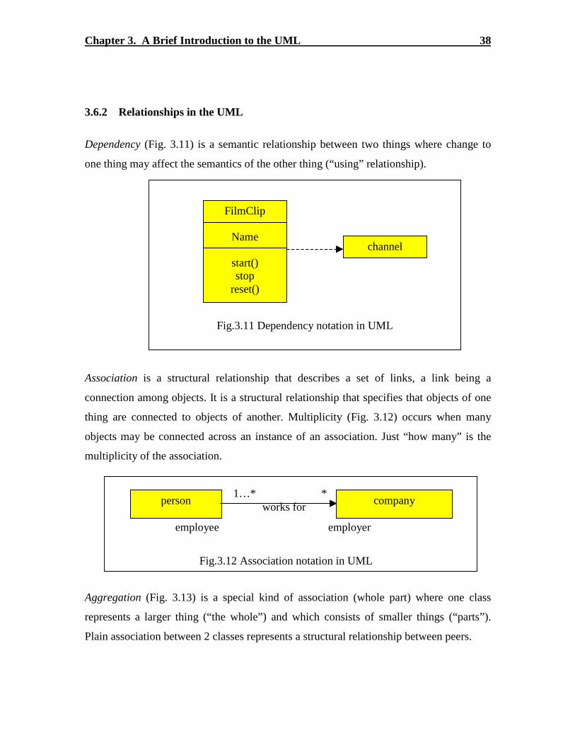
Chapter 3. A Br ief Introduction to the UML 38
3.6.2 Relationships in the UML
Dependency (Fig. 3.11) is a semantic relationship between two things where change to
one thing may affect the semantics of the other thing (“using” relationship).
Association is a structural relationship that describes a set of links, a link being a
connection among objects. It is a structural relationship that specifies that objects of one
thing are connected to objects of another. Multiplicity (Fig. 3.12) occurs when many
objects may be connected across an instance of an association. Just “how many” is the
multiplicity of the association.
Aggregation (Fig. 3.13) is a special kind of association (whole part) where one class
represents a larger thing (“ the whole”) and which consists of smaller things (“parts” ).
Plain association between 2 classes represents a structural relationship between peers.
Fig.3.11 Dependency notation in UML
FilmClip
Name
start()stop
reset()
channel
Fig.3.12 Association notation in UML
person companyworks for
1…* *
employee employer
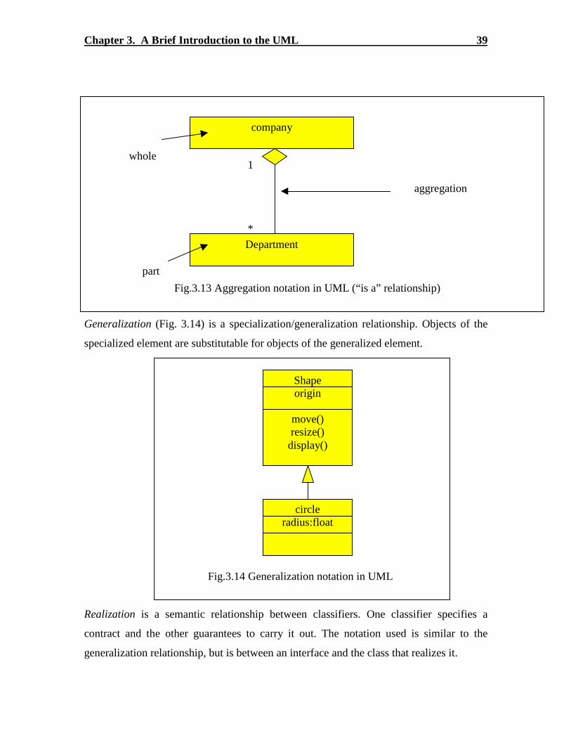
Chapter 3. A Br ief Introduction to the UML 39
Generalization (Fig. 3.14) is a specialization/generalization relationship. Objects of the
specialized element are substitutable for objects of the generalized element.
Realization is a semantic relationship between classifiers. One classifier specifies a
contract and the other guarantees to carry it out. The notation used is similar to the
generalization relationship, but is between an interface and the class that realizes it.
company
Department
1
*
whole
part
aggregation
Fig.3.13 Aggregation notation in UML (“ is a” relationship)
Shapeorigin
move()resize()display()
circleradius:float
Fig.3.14 Generalization notation in UML

Chapter 3. A Br ief Introduction to the UML 40
3.6.3 Diagrams in the UML
Typical diagrams that can be built using the UML are shown and described below.
3.6.3.1 Class Diagram
A typical class diagram looks like the one in Fig.3.15. A single customer may be
associated with multiple customers as shown by the one-to-many association relationship.
A constraint can also be placed on this relationship. Corporate and Personal Customers
are derived from the Customer class.
Order
Date receivedis prepaidNumber
Price
Dispatch()close()
Order
ProductQuantity
Price
Customer
NameAddress
Credit Rating
CorporateCustomer
Contact NameCredit RatingCredit Limit
Remind()
PersonalCustomer
Credit card #
Operations
Generalization
* 1
Association
Attributes
Class
Constrain
{ Orders for acustomer with poorcredit rating must be
prepaid}
1
*
Fig.3.15 A typical UML Class Diagram

Chapter 3. A Br ief Introduction to the UML 41
3.6.3.2 Package Diagram
The following example (Fig. 3.16) shows a typical package diagram in a UML model.
The relationships shown are predominantly weak dependencies, since strong relationships
can be shown at the class diagram level or below.
In this diagram, a central GUI library package is shown and two other User Interface (UI)
packages are seen to be dependent on this package. The UI’s in turn depend upon their
respective back-end packages which in turn have other dependencies as well. This kind of
a package diagram helps illustrate a bird’s eye view scenario of the dependencies in the
system, which can be otherwise difficult to assimilate.
StocksPricer UI
PortFolio UI
GUI Library
StocksPricer
Stocksdatabase Positions Scenario
Manager
PortfolioApplication
Dependency
Package
Fig.3.16 A typical UML package diagram

Chapter 3. A Br ief Introduction to the UML 42
3.6.3.3 Use Case Diagram
The Use Case Diagram example below (Fig. 3.17) illustrates the EIS application dealt
with as a case study in this thesis. The sticky men outside the central system block are the
actors for this system. These actors could be human users, like the EIS Energy Analysts
or a Customer Energy Manager, which itself is a software. However, all systems external
to the system under study are considered to be actors. Use Cases inside the system are
shown and their dependencies are also illistrated. For example the middle tier use case
uses the Database to service requests from the Client software. A Use case diagram is
typically used to capture the requirements of a system and for testing to see if these are
met when the system has been developed.
EISClient
Software
CustomerData
Config tools
DIS Config.tools
Internet <<uses>>
Database
<<uses>>
<<uses>>
Middletier
softwar<<uses>>
<<uses>>EIS
Energy Analyst 1
EISEnergy Analyst 3
EISEnergy Analyst 2
CustomerEnergy
Manager
Fig.3.17 A typical UML Use Case Diagram

Chapter 3. A Br ief Introduction to the UML 43
3.6.3.4 Interaction Diagram – Sequence
A sequence diagram is a type of interaction diagram that emphasizes on the time-ordering
of the messages passed among objects. It can be seen from the example below (Fig. 3.18)
that the entire life span of each object is depicted and new objects created are also shown.
The sequence diagram is a useful diagram to understand the mapping between a use case
and its implementation in source code. Along with the collaboration diagram, it forms the
heart of the UML model constructed.
Fig.3.18 A typical UML Sequence Diagram
an OrderEntryWind
ow
an order an Orderline
a StockItem
prepare()
*prepare()
hasStock:=
check()
[hasStock]remove()
Needsreorder :=needsToReorder()
a ReorderItem
a DeliveryItem[hasStock]
new
[needsReorder]new
creation
Selfdelegation
Message
iteration
Object
Condition
deletion

Chapter 3. A Br ief Introduction to the UML 44
3.6.3.5 Interaction Diagram – Collaboration
Another type of interaction diagram (Fig. 3.19) is the Collaboration diagram, which is
isomorphic to the sequence diagram. In contrast to the sequence diagram, this diagram
shows how objects collaborate among each other, with the time factor de-emphasized.
However, a sequence number is used to show the order of message execution. The
example shown below can be correlated to the sequence diagram in the previous section
to understand the subtle differences between the two views. Though they are perfectly
isomorphic to each other, sequence and collaboration diagrams are useful representations
of the same interactions and it is very difficult to do without either one of them.
Fig.3.19 A typical UML Collaboration Diagram
:Order Entry Window
:Order
Talisker line:orderLine
:Delivery item
talisker stock:Stockitem
:reorder item
1:prepare()
1.1 * [for all order lines]:prepare()
1.1.3:[hasStock] new
1.1.1:[hasStock] := check()1.1.2:[hasStock] remove()
1.1.2.2:[needsReorder] new
1.1.2.1:needsReorderneedsToReorder()
Self delegation
message
Object
Sequence number

Chapter 3. A Br ief Introduction to the UML 45
3.6.3.6 Activity Diagram
An activity diagram is used typically to describe the implementation of use cases. The
emphasis here is on the flow of execution in order to implement the functionality
necessitated by the associated Use Case. It is very useful to depict multithreaded or
parallel execution in the system. For example in the Fig.3.20, after receiving the order,
the assign goods to item activity and the authorize payment activity are executed
concurrently. At the end of the parallel execution the two threads fork back again
together to dispatch the order. There is another useful feature, the swim lanes, which
allow the modeler to distinguish between different threads executed at the same time.
Fig.3.20 A typical UML Activity Diagram
ReceiveOrder
Assign Goods toitem
AuthorizePayment
DispatchOrder
ReorderGoods
CancelOrder
* [for each line item]
[failed]
[succeeded]
[need toreorder]
[stock assigned to all items and payment authorized

Chapter 3. A Br ief Introduction to the UML 46
3.6.3.7 State Diagram
A State Diagram (Fig. 3.21) is used to describe the behavior of an object throughout its
lifetime. The object may respond the different conditions differently based on its current
situation. Therefore a state chart diagram would be most appropriate to describe this kind
of behavior where some stimulant causes the object to change state. An example of a
state diagram applied to an industrial bottling process is shown below, where the different
states and the actions that could cause the state changes are shown.
Fig.3.21 A typical UML State Diagram
Empty Full
SealedBroken
InProgress
Squirt(n)[content+n >= capacity]
capbreak
Squirt(n)[content+n < capacity]

Chapter 3. A Br ief Introduction to the UML 47
3.7 Comments
It would be worthwhile to note that though UML provides a modeling language rich in
semantics, it provides no direction as to the process to employ UML in for a software
development effort. This was done intentionally to allow the users of UML to design and
adopt processes suited to their respective and sometimes unique environments, platforms
and development efforts. There are may processes suggested currently for employing
UML in a software development process, one of which is the Unified Software
development process by Booch, Rumbaugh and Jacobson.
There are currently more than 20 different tools that provide for support in software
development using the UML notation. Most of these tools support round-trip engineering,
and many offer other capabilities like configuration management etc. However,
Rational’s UML tool, ROSE (heretofore referred to as Rose) is certainly the most
recognized Object modeling tool in the market. Rose’s market share exceeds that of its
four closest competitors, combined! There are other powerful tools like GD pro,
Paradigm Plus and StP which offer comparable, if not better, features as Rose does. On
the other hand there are some basic drawing tools like Visio that allows the modeler to
construct the diagrams without any language support or other advanced features offered
by Rose and other tools.
After having observed the CASE tools industry for the past few years, the author would
like to emphasize the notion that this industry is actually in its infancy. In the future more
powerful tools with advanced and intelligent features can be expected to roll out, making
the documentation and management of complex software more developer friendly than
ever.

48
Chapter 4
Preliminary Work Before Reverse Engineer ing
The greatest part of the software maintenance process is devoted to reading
documentation, scanning the source code, and understanding the changes to be
made.
Spencer Rugaber

49
4 Preliminary Work Before Reverse Engineer ing
4.1 Gener ic Ideas
Some generic ideas imbibed from previous work and intuitive notions were decided upon
initially to set up the environment for the Reverse Engineering effort. The various steps
adopted as part of the effort can be described as follows.
4.1.1 Collect the var ious ar tifacts
There are several artifacts in any software system like the source code, design documents,
specification documents and the Developer knowledge/experience that are of vital
importance for the Reverse Engineering effort. These are gathered together in an effort to
build the knowledge base for the software system.
4.1.2 Develop functional exper ience
Understanding the functionality of the software system aids in the Reverse Engineering
process. An abstract understanding of the functions that the system performs is the first
step towards understanding the works inside.
4.1.3 Establish control over building the software system
To determine the level of control achieved over the software system, it is essential that
the software be compiled and built from scratch using the artifacts mentioned in 4.1. This
Chapter 4. Preliminary Work Before Reverse Engineer ing 50
vital step could help ensure that certain artifacts used by the developers for peripheral
testing and other verification purposes are eliminated from the purview of the system
artifacts. This essentially refines the sample space of the reverse engineering problem,
besides establishing the validity of the repository made available.
4.1.4 Evaluate tools for Reverse Engineer ing
A tremendous amount of work is being done currently in the Reverse Engineering area
and some new tools are being developed to aid the same. Therefore, evaluating and
choosing one such tool to suit the problem domain is another step of paramount
importance. For example, to reverse engineer a project using the Java programming
language, there is relatively new tool named “Visicomp” which, according to its
developers, helps in visualizing and understanding a Java software system. Besides this,
the major visual modeling toolmakers plan to integrate a Reverse Engineering module
into the modeling tools in the future.
4.1.5 Select the visual modeling medium
Logically, the next step is to decide upon the means to communicate the understanding
achieved at the end of the Reverse Engineering effort. At the point in the software-
engineering era when thesis is being written, the Unified Modeling Language (UML) has
become the de-facto standard adopted by the software industry to visualize and
communicate a software system design. Therefore it is strongly recommended that a
suitable modeling tool be chosen that supports UML in the paradigm of the software
system being reverse engineered.
4.1.6 Build the architectural model of the system
The architecture or the physical model of the system artifacts could be built using the
UML and these will help in communicating the relationships among the physical artifacts

Chapter 4. Preliminary Work Before Reverse Engineer ing 51
in the system. For example, the relationship between the various classes in a typical
Object Oriented (OO) software system would help convey the static architecture of the
classes.
4.1.7 Adapt to a suitable development environment
Another vital choice would be that of a suitable development environment that would
enable stepping through the code and understanding its functionality by setting
breakpoints etc. A typical example would be the choice of an Integrated Development
Environment (IDE) like Symantec Visual Café to step through a software system written
in the Java programming language. Compiling the system and executing the same from
an IDE is usually a non-trivial task for systems that were not developed using an IDE in
the first place.
4.1.8 Debug the system in the development environment
The source code of the software system can be stepped-through in the development
environment chosen and the control flow of the system could be understood.

Chapter 4. Preliminary Work Before Reverse Engineer ing 52
4.2 Case Study: Exper ience in setting up the environment for the EIS Client
The steps detailed above were used for reverse engineering the application and the
experience during the effort is cited below.
4.2.1 Collection of the ar tifacts
With help from the client, all the artifacts used in the development and deployment of the
project were gathered and the scanty documentation was thoroughly pored over to gain
whatever knowledge was available.
4.2.2 Functional exper ience
The application was tested and used with sample data to gain an understanding into the
workings of the system.
4.2.3 Control over building the software system
The application was built after consulting with the developers and determining the errors
and inconsistencies in the documentation. The EIS Client source had make files written
for them and the application could be built using these make files from the bash shell.
This went a long way in giving an idea about the directories and files used in the project.
4.2.4 Tool for Reverse Engineer ing
There were numerous tools that could be used for reverse engineering. However, many of
these tools were designed for Forward engineering a project development life cycle. After
analyzing many options it was determined that the UML is the standard modeling
language adopted by the Object world. Besides, UML has been documented extensively
Chapter 4. Preliminary Work Before Reverse Engineer ing 53
and is being widely used in the industry and academia. Therefore UML is the tool chosen
for the purpose of this reverse engineering effort.
4.2.5 Choice of the visual modeling medium
Numerous tools are available in the market today for using the UML. However, very few
of these tools have notable capabilities for reverse engineering. Rational Rose 2000 is the
most advanced of these tools and it has quite a few reverse engineering tasks built in.
Moreover Rose occupies prime of place in the UML tools domain and has a market share
of over four times the combined market share of its 4 nearest competitors. Also since it
supported the Java language and had been tried and tested for use with Java, the Rational
Rose 2000 Professional J version was chosen as the modeling medium.
4.2.6 The architectural model of the system
The static architecture of the EIS Client application was built using the Rose J tool and
the relationships between and among the various components or the packages in the
system was shown.
4.2.7 Adaptation to a suitable development environment
The EIS Client application was adapted to the Visual Café IDE and the application can
now be compiled, built and executed directly from this environment. This proved to be a
tremendous step forward in understanding the innards of the application since the
environment allows debugging and step by step execution of the application.
The process followed to Reverse Engineer the application and a sample of the diagrams
developed are described in chapter 5 of this thesis.

54
Chapter 5
A Reverse Engineer ing Process:
Case Study
Man cannot survive except by gaining knowledge, and reason is the only means togain it. Reason is the faculty that perceives, identifies and integrates the materialprovided by his senses.
John Galt (A.R)
55
5 A Reverse Engineer ing Process: Case Study
5.1 Introduction and Motivation
The previous chapter dealt with the issues that a typical Reverse Engineering effort
would encounter as stumbling blocks. However, the biggest and most underestimated
block that has to be overcome is that of defining the process to be adopted for Reverse
Engineering. The emergence of UML as a widely used CASE tool for Object Oriented
software development has happened only due to the emergence of well defined processes
for forward engineering (as defined in Chapters 1 and 2). There are quite a number of
such processes defined by experts in the development community, a good example for
which is the “Unified Software Development Process” defined by Booch, Rumbaugh and
Jacobson. Though such processes emphasize on the importance of correlation between
the model and the implementation, a clearly defined process for reverse engineering as a
part of the round trip engineering during development is not presented. The definition of
such a process may not be critical to a development effort, but maintenance or reverse
engineering effort makes it absolutely essential.
The intention of this work is to define a suitable process for Reverse Engineering, which
itself is based on the experience gained while trying to reverse engineer an industry
strength software product, namely the EIS Client discussed earlier. Important concepts
necessary to understand the scenario are presented first, followed by the definition of the
process itself, which is followed by a review of the experience in using this process for
the case study.

Chapter 5. A Reverse Engineer ing Process: Case Study 56
5.2 Related Work
This work [22] was stimulated by a previous work on defining a process for reverse
architecting, as opposed to reverse engineering. It is a description of the process that was
adopted in reverse architecting a case study (discussed in Chapter 2 of this thesis).
However, it is limited to extracting the static architecture of a system from the source
code. The case study is an embedded software system written in the C programming
language. An approach to the task of reverse architecting is defined followed by a
description of the experience with the case study. This thesis work takes off on the
platform provided by this article, and builds on it to describe a reverse engineering
process, and the experience obtained while using it on a case study. This thesis work is
different in that the case study is an object oriented software system, and that the CASE
tool used is UML. The process itself had to be redefined to incorporate the complexities
of reverse engineering an OO software system and the lack of available tools for the
same.
5.3 Abstraction
Problem and Solution domains:
A distinction between the problem and solution domains has to be model. There are two
ways to view software systems’ functionality. From the perspective of the user, the
requirements of the system are specified in the problem domain. The problem domain
outlines what the system is supposed to do. From the perspective of a developer, the
system can be viewed in the solution domain, which specifies how the system achieves
the tasks specified in the problem domain.
Since reverse engineering itself is a process requiring abstraction at different levels, the
system artifacts should be constrained to five levels of abstraction.

Chapter 5. A Reverse Engineer ing Process: Case Study 57
Requirements:
The user requirements represent the highest level of abstraction at which the system can
be represented. The functionality is expressed at a fine grain level without any emphasis
whatsoever on the implementation dependent details. The software system is expected to
satisfy the requirements specified. The requirement specification document is typically
the product of a system analyst’s interactions with the potential users and system experts,
resulting in a text document supported by figures and diagrams.
Features:
A Use Case is a functional requirement expected of the system, and could potentially be a
uniquely identifiable entity for development. The features bridge the gap between the
artifacts that are being developed and the requirements specified. They are useful in
testing the system functionality during and after development. Use Cases can be directly
mapped to the Use Cases in UML.
Architecture:
The architecture of a system specifies how the artifacts of the system combine together to
implement the desired functionality. The component diagrams and sequence diagrams
can combine well with the class diagrams in specifying the system architecture in UML.
Design:
The internal design and implementation of the system artifacts are the elements of the
design layer of abstraction. The classes, activity diagrams and state chart diagrams can be
mapped to the design level documentation. The design only goes to show the functional
decisions made while building the system, which usually resides in the minds of the
developers and is rarely conveyed in any form. Design entities like classes, structures,
and user-defined data types etc. are modeled in this layer of abstraction.

Chapter 5. A Reverse Engineer ing Process: Case Study 58
Implementation:
This is the lowest level of abstraction and constitutes those artifacts that implement the
functionality of the system. It is done using a programming language and is usually rich
in details. Source files, directories and file systems typically make up the implementation
layer.
Implementation
Design Design Design
Architecture
Requirements
Features
abst
ract
ion
Fig 5.1 Levels of abstraction (Courtesy: Riva C. [22])
prob
lem
dom
ain
solu
tion
dom
ain

Chapter 5. A Reverse Engineer ing Process: Case Study 59
5.4 A Process for Reverse Engineer ing
Reverse Engineering is best-defined [1] as “ the process of analyzing a subject system to
identify the system’s components and their inter-relationships and to create
representations of the system in another form or at a higher level of abstraction.” A more
fine-grained definition of this process is provided as a result of our work in this thesis.
This process is aimed at assisting the activity of reverse engineering an object oriented
software system. Our approach is depicted in Fig 5.2, and each phase of the process is
encapsulated in a dashed box, artifact(s) in the process in rectangles, and activities in
ellipses. A description of each phase of our approach to reverse engineering follows.
5.4.1 Definition of goals of reverse engineer ing
Before beginning the reverse engineering activity, it is important to identify the goals and
limitations of the effort. Typical industry strength OO systems are huge and complex, and
reverse engineering such a system could be limited to the extraction of the architectural
design from the source code, for example. A re-engineering effort might entail the
adoption of a process to define the feature level abstraction of the system functionality.
Reverse engineering is seldom a time bound activity, and a clear definition of the how far
to go as a trade off against the cost involved is necessary. The effort is also expected to
be iterative and incremental, and could potentially lead to a bigger and more complex
artifact than the source code. It is therefore important to keep the “big picture” in mind
and focus on predetermined goals.
The documentation available for the software system, the nature and size of the source
code itself, and suggestions and ideas from the system experts or developers would be the
inputs to develop such milestones. Reverse engineering is an active area of research
currently, and it would be useful to survey the available tools and other products of
research before embarking on the project.

Chapter 5. A Reverse Engineer ing Process: Case Study 60
5.4.2 Development of a Feature Descr iption
This phase involves developing models for the feature level of abstraction described
earlier. The reverse engineer would first benefit by learning the usage of features offered
by the system and its actions and reactions to stimuli. Reading the fine print of the user
documentation would also provide a better understanding of the system’s capabilities.
The development of a feature description, say a Use Case diagram in UML, documents
the functional features of the system. This could be useful for maintenance as well as re-
engineering. This description can also be mapped to the requirement specifications for
the system to verify the success of the development effort.
Ideally, the development of the system should have begun with the development of a
feature description, in the absence of which, this step would enable to understand some of
the reasons driving the design decisions made by the developers of the software.
5.4.3 Extraction of the Source Model
Extracting an abstract model for the source code could potentially be the most difficult
part of the reverse engineering process. The source code is a flat view of the system as
extracted from the source files. One or more of the following methods can be used
together to gain an understanding of the source code functionality and to model it at an
abstract level.
1. Developers documentation
Software developers normally document important and complex portions of the source
code with comments and other notes. OO software developers typically provide the UML
class diagrams for the complex artifacts in the code.

Chapter 5. A Reverse Engineer ing Process: Case Study 61
2. Debug source code
Stepping through the source code using a development environment would provide vital
clues about the flow of control in complex software projects. This could prove especially
useful for OO systems since they are more complex and non-intuitive than sequential
programs. For example, object interactions in an OO system can be identified and
modeled by running through the code and by closely watching the objects of interest
during their transactions.
3. Use of parsers and other tools
There are several tools available that parse through source code written in a variety of
programming languages and provide a description in an abstract notation. For example,
the Rigi tool parses the source code and identifies the dependencies between components
and files in the architecture. The use of such tools can save some effort and time for the
reverse engineer. However, the notation used for the abstract representation, the level of
abstraction that can reached, and the flexibility offered by the tool to control such
decisions should drive this choice.
Certain CASE tools for OO programming languages offer support for reverse engineering
static information like attributes and operations of a class into a visual representation.
This and other advanced features could reduce some of the rigor involved in reverse
engineering source code. Optimum selection of the level of abstraction required has to be
made to ensure that the reverse engineered document itself does not become a more
complex legacy than the source code itself. The underlying goal should always be
paramount, “communication.”
5.4.4 Abstraction of the Architectural Model
The architectural model can be extracted with the understanding gained out of performing
the above steps and reading the developers documentation. Several OO CASE tools
provide the functionality of extracting the architectural information by parsing the source

Chapter 5. A Reverse Engineer ing Process: Case Study 62
code and by understanding some of the static dependencies between the various artifacts.
Besides these, the models extracted from the source code are a useful source to
understand the architecture of the system. Abstracting away the inner details of the source
model would yield the architectural model for the system.
The component and package diagrams in UML can convey a wealth of information about
the architecture of the system, much more than a lengthy textual discussion.
5.4.5 Consolidation
Once the models are developed at the different levels of abstraction described above, it is
important to correlate them to verify and glean away any discrepancies. Another useful
exercise would be to try to map the feature description to the source and architectural
models, which would make the abstractions completely connected among each other.
Redocumentation of the models will increase comprehension about the system and also
offer scope for improving the models before they are released. The result of this phase of
the process is the reverse engineered documentation, which can then be utilized.
5.4.6 Utilization
This phase consists of analyzing the documentation generated by reverse engineering and
using the understanding gained for purposes like maintenance of the system or for
suggesting improvements to the system. As suggested in the literature, the result of
reverse engineering would also aid in re-engineering or in the development of a new
system.

Cha
pter
5.
A R
ever
se E
ngin
eeri
ng P
roce
ss:
Cas
e St
udy
63
Do
cum
enta
tio
nS
ou
rce
Co
de
Sys
tem
Exp
erts
dev
elo
p
Iden
tify
Go
als
Do
cum
enta
tio
nF
un
ctio
nal
ity
dev
elo
p
Use
Cas
e D
escr
ipti
on
Do
cum
enta
tio
nC
AS
E T
oo
lsD
ebu
gg
ing
extr
act
So
urc
e co
de
mo
del
Do
cum
enta
tio
nC
AS
E T
oo
ls
abst
ract
Arc
hit
ectu
re M
od
el
Co
rrel
ate
Mai
nte
nan
ce
An
alys
is Imp
rove
men
t P
lan
s
Des
ign
Art
ifac
t
Pha
se 2
Pha
se 5
Pha
se 3
Pha
se 4
Pha
se 6
Pha
se 1
Fig
5.2
The
RE
P ph
ases

Chapter 5. A Reverse Engineer ing Process: Case Study 64
5.5 Case Study – the EIS Client Application
As described in previous chapters, this thesis grew out of a reverse engineering project
undertaken here at Virginia Tech. The EIS Client was reverse engineered using the
approach described as a process for reverse engineering in the previous section (5.4).
This section deals with the experiences thereof.
5.5.1 Definition of goals
The EIS Client was a huge and complex Java application inherited by our client as a
legacy system. The goals for this project were set forth as follows.
1. To build a model that would scale down the learning curve for someone trying to
understand the system.
2. To develop means of compiling the application in a suitable environment for
debugging and maintenance.
3. To trace the flow of control in the source code and identify the major structural
classes in the OO application.
4. To limit the models to a high level of abstraction and to abstract away the richness of
the implementation level details in the source code, unless absolutely necessary.
5. To limit the model to the source code developed for this application. The EIS Client
uses several third party libraries like the KL Group’s JClass, Free Software
Foundation’s open source etc. Extensive documentation and comments accompany
these programs. Therefore the scope of this project was restricted to modeling the
source code developed for the EIS Client.
6. To model the interactions between key classes, with least emphasis on modeling the
functionality of single classes.
7. To keep the final model as simple as possible, since the intent of the reverse
engineering project is not to generate extensive documentation for the source, but to
generate a compact model containing only those artifacts critical to the application.

Chapter 5. A Reverse Engineer ing Process: Case Study 65
5.5.2 Feature Descr iption
One of the first steps taken while reverse engineering the EIS Client was to build the Use
Case description for the system as a whole from a requirements perspective. This was
achieved using the following steps.
1. The first step was to learn to use the EIS Client application with help from the user
guide and from our client. We were allowed to access some sample data from the
server, and a good understanding about the functional aspects of the application was
developed.
2. By reading some of the developers documentation.
3. By building a Use Case diagram at the system level and by providing fine grain Use
Case diagrams wherever necessary.
The following example shows the system level Use Case diagram (Fig 5.3) built for the
EIS Client. Each use case was documented textually to provide more understanding about
its functionality.

Chapter 5. A Reverse Engineer ing Process: Case Study 66
5.5.2.1 Use Case Diagram for the EIS Client Application – top level
Diagram Documentation
The requirements of the EIS Client system is captured using this top level Use
Case description.
EIS Client Application Use CasesAnalyze daily demand
Analyze time interval
Analyze threshold
Analyze cummulativethreshold
Analyze summary
Analyze weekly demand
Analyze as metered
Analyze needle
Analyze simutaneous events
Setup critical events
View critical events
Start and Validate User
View vitals
View analysis types
<<extend>>
<<extend>>
<<extend>>
<<extend>>
<<extend>>
<<extend>>
<<extend>>
<<extend>>
<<extend>>View intro. to critical events
<<extend>>
<<extend>>
View Analysis Modules
<<include>>
<<extend>>
<<extend>>
<<extend>>
EIS User
Fig 5.3 Use Case Diagram for the EIS Client

Chapter 5. A Reverse Engineer ing Process: Case Study 67
The EIS client user is the actor who double-clicks on the EIS Client icon and
starts the application. He also types in the validation information (Username and
password) when the system shows the authorization request window.
The View Analysis use case begins just after the user starts the EIS Client
Application. The system first validates the user (Validate user use case), then
shows the system modules: Analysis, Critical Events, and Vitals. The use case
ends when the user selects any one of the modules.
The Start and Validate User use case begins when the user starts the EIS Client
Application. It starts the application, verifies the version and validates the user.
The system prompts the user to enter his/her user name and password. If an
invalid user name or password is entered, the system re-prompts the user to
enter a valid user name and password. The use case ends when a valid user
name and password are entered. This use case is described by a fine grained
use case diagram that follows this description in 5.5.2.2.
The View Vitals use case begins when the user selects Vitals module. It provides
the capability to view site specific information. The system shows the user the
specific information on chosen sites. The use case ends when the user chooses
any one of the other analysis modules.
The View Intro to Critical Events use case begins when the user selects Critical
Events module. It provides the capability to view and select setting up or viewing
critical events. The system shows the user introduction to critical events with two
options: Setup Critical Events and View Critical Events. The use case ends when
the user selects either one of the two options.
The View Analysis Types use case begins when the user selects Analysis
module. It provides the capability to view and select the analysis types. The
system shows the user analysis types: Summary, Daily Demand, Weekly

Chapter 5. A Reverse Engineer ing Process: Case Study 68
Demand, Time Interval, As Metered, Threshold, Needle, Cumulative Threshold,
and Simultaneous Events.
The View Critical Events use case begins when the user selects View Events
option. It provides the capability to view the latest occurrence of a critical event.
The user views the latest occurrence of a critical event. The use case ends when
the user selects another option or other modules.
The Setup Critical Events use case begins when the user selects Setup Events
option. It provides the capability to define critical events based on saved
analyses that represent critical events’ definitions. The user sets up critical
events by giving the critical events information. The use case ends when the user
selects another option or other modules.
The Analyze Daily Demand use case begins when the user selects Daily
Demand analysis type. It provides the capability to display a summary of each
15-minute interval. The user sets up the date range and chooses site(s) for
analyzing, and the system prompts the user to select measurement channels
(power, energy cost, or both), and then displays the name and type of the site(s)
and the daily demand. Day of week or month of year can set the date selection
criteria. The data can also be displayed in graph by selecting Display Graph
option. The use case ends when the user selects other analysis types or
modules.
The Analyze Summary use case begins when the user selects Summary
analysis type. It provides the capability to display a general summary (peak,
average, minimum and sum). The user sets up the date range and chooses
site(s) for analyzing, and the system prompts the user to select measurement
channels (power, energy cost, or both), and then displays the name and type of
the site(s) and the summary. The date selection criteria can be set up by time of
day, day of week, or month of year. The data can also be displayed in graph by

Chapter 5. A Reverse Engineer ing Process: Case Study 69
selecting Display Graph option. The use case ends when the user selects other
analysis types or modules.
The Analyze Time Interval use case begins when the user selects Time Interval
analysis type list. It provides the capability to display data on daily, monthly,
yearly or custom month interval. The user sets up the date range, display interval
and chooses site(s) for analyzing, and the system prompts the user to select
measurement channels (power, energy cost, or both), and then displays the
name and type of the site(s) and the data on time intervals. Day of week or
month of year can set up the date selection criteria. The data can also be
displayed in graph by selecting Display Graph option. The use case ends when
the user selects other analysis types or modules.
The Analyze Weekly Demand use case begins when the user selects Weekly
Demand analysis type. It provides the capability to display a summary of each
day of the week. The user sets up the date range and chooses site(s) for
analyzing, and the system prompts the user to select measurement channels
(power, energy cost, or both), and then displays the name and type of the site(s)
and the weekly demand. Day of week or month of year can set up the date
selection criteria. The data can also be displayed in graph by selecting Display
Graph option. The use case ends when the user selects other analysis types or
modules.
The Analyze Threshold use case begins when the user selects Threshold
analysis type. It provides the capability to display violations of chosen
thresholds. The user sets up the date range, grouping and chooses site(s) for
analyzing, and the system prompts the user to select measurement channels
(power, energy cost, or both), and then displays the name and type of the site(s)
and the violations of the thresholds. The date selection criteria can be set up by
time of day, day of week, or month of year. The data can also be displayed in

Chapter 5. A Reverse Engineer ing Process: Case Study 70
graph by selecting Display Graph option. The use case ends when the user
selects other analysis types or modules.
The Analyze as Metered use case begins when the user selects As Metered
analysis type. It provides the capability to display the as metered data (currently
15-minute interval). The user sets up the date range and chooses site(s) for
analyzing, and the system prompts the user to select measurement channels
(power, energy cost, or both), and then displays the name and type of the site(s)
and the as metered data. The date selection criteria can be set up by time of day,
day of week, or month of year. The data can also be displayed in graph by
selecting Display Graph option. The use case ends when the user selects other
analysis types or modules.
The Analyze Needle use case begins when the user selects Needle analysis
type. It provides the capability to display peaks of a selected magnitude and
width. The user sets up the date range, grouping and chooses site(s) for
analyzing, and the system prompts the user to select measurement channels
(power, energy cost, or both), and then displays the name and type of the site(s)
and the needles. The date selection criteria can be set up by time of day, day of
week, or month of year. The data can also be displayed in graph by selecting
Display Graph option. The use case ends when the user selects other analysis
types or modules.
The Analyze Cumulative Threshold use case begins when the user selects
Cumulative Threshold analysis type. It provides the capability to display
violations of chosen cumulative thresholds. The user sets up the date range,
accumulation interval, grouping and chooses site(s) for analyzing, and the
system prompts the user to select measurement channels (power, energy cost,
or both), and then displays the name and type of the site(s) and the violations of
the cumulative thresholds. The date selection criteria can be set up by time of
day, day of week, or month of year. The data can also be displayed in graph by

Chapter 5. A Reverse Engineer ing Process: Case Study 71
selecting Display Graph option. The use case ends when the user selects other
analysis types or modules.
The Analyze Simultaneous Events use case begins when the user selects
Simultaneous Events analysis type. It provides the capability to display
simultaneous violations of chosen thresholds for a primary and secondary
measurement type. The user sets up the date range, grouping and chooses
site(s) for analyzing, and the system prompts the user to select measurement
channels (power, energy cost, or both), and then displays the name and type of
the site(s) and the simultaneous violations of the thresholds. The date selection
criteria can be set up by time of day, day of week, or month of year. The data can
also be displayed in graph by selecting Display Graph option. The use case ends
when the user selects other analysis types or modules.
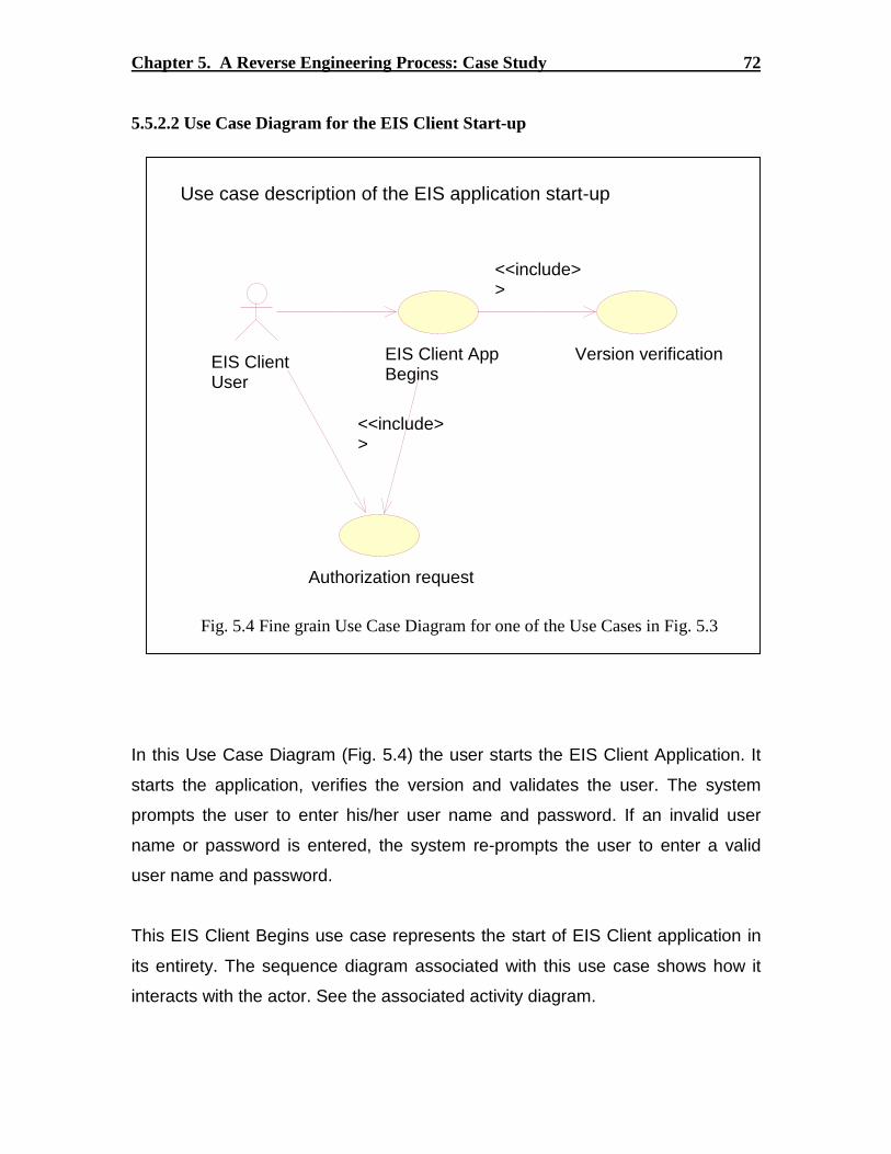
Chapter 5. A Reverse Engineer ing Process: Case Study 72
5.5.2.2 Use Case Diagram for the EIS Client Star t-up
In this Use Case Diagram (Fig. 5.4) the user starts the EIS Client Application. It
starts the application, verifies the version and validates the user. The system
prompts the user to enter his/her user name and password. If an invalid user
name or password is entered, the system re-prompts the user to enter a valid
user name and password.
This EIS Client Begins use case represents the start of EIS Client application in
its entirety. The sequence diagram associated with this use case shows how it
interacts with the actor. See the associated activity diagram.
Fig. 5.4 Fine grain Use Case Diagram for one of the Use Cases in Fig. 5.3
Version verificationEIS Client AppBegins
<<include>>
Authorization request
<<include>>
EIS ClientUser
Use case description of the EIS application start-up

Chapter 5. A Reverse Engineer ing Process: Case Study 73
The version verification use case relates to the verification done in the
DSGJavashell class. The current version number of the jre.exe is determined
and checked for compatibility.
The user has to be authenticated before he can be allowed to use the EIS
application and to access relevant data. This use case handles the authorization
request and asks the user to enter the user name and password. The system
then sends the data across the network to the server and validates the user. A
HTTP connection is also established in this phase.
5.5.2.3 Activity Diagram for the EIS Client Begins Use Case
This activity diagram (Fig. 5.5) describes the activities and actions initiated by the
EIS Client Begins Use Case. First, checks the current version of the jre.exe file
being used to run the EIS Client application. Loads all the EIS Client classes in
the application and raise exceptions whenever a class file is not found or is
inaccessible. This activity is implemented in the Loader.java class, which is
generated by the makefile.

Chapter 5. A Reverse Engineer ing Process: Case Study 74
Check jre version
Authenticate the user
Establish http connection
Is connection established?
Yes
Request user to re-enter network info
No
Retrieve data from Datapult Central
Start the User Interface
Load all classes
Activity Diagram description for the Datapult Begins Use Case
Fig 5.5 Activity Description for the EIS Client Begins Use Case

Chapter 5. A Reverse Engineer ing Process: Case Study 75
5.5.3 Extraction of the Source Model
Analyzing the source code was the most challenging part of the project. Several modules
of the source were scantily documented, and debugging the source was the primary
method used to extract the model as an abstraction. The reasons for this decision are
discussed further.
1. Developers documentation
Certain important classes and objects in the system were documented textually by the
developers. These documents were scanned thoroughly for clues about the critical
modules in the application. In this case, the developers’ documentation provided for
knowledge about the classes that implement the structure of the client application. The
classes responsible for creating the various frames in the application was the most
important information contained in these documents.
2. Use of parsers and other tools
Though there are several parsers and other reverse engineering tools available, very few
of them had support for the Java programming language. Some tools that were
programming language independent were not flexible enough to accommodate specific
reverse engineering needs like restraining the tool from modeling a third party library.
One specific tool that was evaluated for this project is Visicomp, a tool supposedly useful
for reverse engineering complex Java projects. It was indeed a powerful tool, but we
could not use it for this project due to several reasons. Two of them being that Visicomp
generates non-UML graphical descriptions after reverse engineering, and there being no
flexibility in controlling the tool while it reverse engineers the software. The EIS Client
application being as huge as it is, the tool could not handle the size and complexity. For
the most part, it generated a complex mesh of complete connected graphs. Hence a
decision was made to stick to debugging the source code in an IDE.

Chapter 5. A Reverse Engineer ing Process: Case Study 76
However, OO CASE tools like Rational Rose support UML and allow very limited, albeit
convenient support for reverse engineering. The Rose tool can reverse engineer OO
software’s classes into the model, then allows the reverse engineer to use it in his
diagrams. However, the support it offers is limited to extracting the static information and
all the dynamic information has to be understood by debugging the source.
3. Debugging
This was found to be the best method of understanding program flow and the interaction
between the various classes in the application. Every class had several implementation
level functionalities like exception handling etc., which were largely ignored for the
purpose of reverse engineering. The emphasis while debugging was towards finding vital
clues as to how objects interact to implement a Use Case, and ignoring interactions that
effect other Use Cases not relevant to the view being presented. The Visual Café IDE was
used to debug the EIS Client in the Java environment.
5.5.3.1 Class Diagram for the EIS Client Begins Use Case
The class diagram in Fig 5.6 shows the major classes that implement the
functionality seen during the beginning of the application. The interactions
between these classes or their objects and messages passed among them are
described by means of sequence diagrams, one of which is used to illustrate the
point in Fig. 5.7.

Chapter 5. A Reverse Engineer ing Process: Case Study 77
Fig 5.6 Example Class Diagram showing classes which implement the EIS Clientstart-up
java
sunDSGJavaShell
$ NORMAL : int =0$ RESTART : int =11$ REDIRECT_FAILED : int = 12
main()windowClosing()actionPerformed()DSGJavaShell()
Loader
Loader()
DSGAppLoader
$ FRAME_WIDTH : int =400$ FRAME_HEIGHT : int =200$ DIALOG_WIDTH : int =420$ DIALOG_HEIGHT : int =100$ LICENSE_WIDTH : int =500$ LICENSE_HEIGHT : int =280$ NORMAL : int =0$ RESTART : int =11$ REDIRECT_FAILED : int =12$ UPDATE_PERCENT : long = 5imageWidth_ : int = 0imageHeight_ : int = 0timeout_ : int =0authCancelled_ : boolean = falsehostPortErr_ : boolean = falsecloser_ : ErrorWindowAdapterrestartApp_ : boolean = falsesysExit_ : boolean = trueupdate_ : boolean = falseaccepted_ : boolean = false
main()actionPerformed()DSGAppLoader()imageUpdate()paint()update()doit()finishLoading()deleteDirContents()unzipArchive()setupProperties()loadFileRecs()verifyVersions()updateFiles()copyFile()setPercent()
HTTPClient
Handler
Handler()openConnection()
(from http)
EIASApp
$ TIMEME : boolean = false$ DEBUG : boolean = false$ APP_WIDTH : int =800$ APP_HEIGHT : int =600$ DEFAULT_COMMAND_INVOKER_TIMEOUT : long = 1000 * 60 * 5$ port_ : int = -1$ acceptConnection_ : boolean$ commandInvokerTimeout_ : long = DEFAULT_COMMAND_INVOKER_TIMEOUTcanceled_ : boolean = falseerrorDisplayed_ : boolean = false
singleton()main()getFrameManager()messageDelivery()init()init()callback()getPort()requestConnection()closeConnection()setConnectionTimestamp()displayError()
-$singleton_
This class diagram shows the primary classes that interact during the beginning of the application.

Chapter 5. A Reverse Engineer ing Process: Case Study 78
5.5.3.2 Interaction Diagrams for the EIS Client Star t-Up
These interaction diagrams (Fig. 5.7 and Fig. 5.8) show how the objects
combine to start up the EIS Client application. They realize the EIS Client start
and Validate user use cases. This is a very high level view of the system and
their interactions. More details can be understood from the source code.
The DSGJavaShell is invoked when the user double clicks on the icon on the
desktop.
Fig. 5.7 Sequence Diagram that describes the application start-up
Fig. 5.8 Collaboration Diagram that describes the application start-up
:DSGJavaShell
: (LogicalView::com::dsg::apploader::DSGAppLoader)
: EIASApp
3: singleton( )
Interaction that implements the start of the Datapultapplication
1: Runtime.getRuntime.exec(appCmd)
2: main
: DSGJavaShell : (Logical View::com::dsg::apploader::DSGAppLoader)
: EIASApp
Runtime.getRuntime.exec(appCmd)
main
Sequence diagram that describes the start-up of the application at a high level
singleton( )

Chapter 5. A Reverse Engineer ing Process: Case Study 79
Diagram Documentation for source-code model
The DSGJavaShell class is the topmost class in the hierarchy of the EIS Client
application. When the application is started, the control transfers to the
DSGJavaShell Class. The arguments are passed to its own constructor where a
new process is created. The DSGAppLoader class is executed from here by a
separate process generated by the Runtime class.
The process handler "app" is held here and it is used to wait for the process to
complete. If the process returns a RESTART command, the process creation
routine is repeated again.
The EIASApp class loads the application by calling its own constructor and also
creates the various GUI components that come up during the initialization of the
application.
The DSGAppLoader class is one of the most important classes in the EIS Client
application. The EIASApp class makes the initializations for the graphical
interfaces that adorn the application and also handle the HTTP connection
request/closure etc. The classes that actually implement the GUI are described in
other class and sequence diagrams.
More such class and interactions diagrams illustrate the EIS Client application’s source
code implementation. The level of abstraction evident here is typical of the intention of a
reverse engineer. The goal is to generate models less rigorous than the source code itself.

Chapter 5. A Reverse Engineer ing Process: Case Study 80
5.5.4 Abstraction of the Architectural Model
Abstracting the architectural description was an ongoing process throughout the length of
the project. However, the static architecture of the system artifacts was identified in the
beginning, and incremental changes were made as more information was learnt.
Component diagrams were built in UML and the relationships among the components
were visually represented by a dependency relationship between them. Major packages
were also identified in these diagrams and this graphical view would simplify the first
time viewer’s effort to understand the architectural layout of the software. One such
component view is shown here as an example (Fig. 5.9).
This component diagram shows the weak dependency relationships among the
components and packages used in the project. This also is a holistic view.
Typically dependencies are due to the import statements in the Java files.
EIASApp
HTTPClient
httpsshttp
ie
Loader
comjclass
QuickDateGenerator
http
Component Diagram that describes the EIS Client applications component/package relationships
Fig 5.9 Architectural description of the application

Chapter 5. A Reverse Engineer ing Process: Case Study 81
5.5.5 Consolidation
Once the various models were built, the consolidation phase took hold. The models were
studied again in light of the goals specified during the beginning of the project. Complex
models that could potentially be unclear than the source code were removed from the
model. Some models were enhanced when they were attached to another view of the
system. For example, the EIS_start Use Case diagram was substantiated by the
implementation views in the class diagram and sequence/collaboration diagrams that
describe the classes and their interactions.
For the maintenance engineer who is concerned only about the start portion of the
application for debugging, the use case diagram encapsulates the functionality, the class
and component diagrams show key elements in its structure, and the sequence diagrams
show the interactions among objects that implement this function. Several such additions,
relationships and corrections were made to the constructed models during this phase.
5.5.6 Utilization
The end result of this project was one coherent UML model that correlates all the
knowledge gained. Care was taken to ensure that the model was not another legacy
system handed to the client. Analyzing the UML model generated and using it for future
maintenance and development would determine the utility of this reverse engineering
effort. The model developed using this case study has been submitted along with this
thesis (dpult_description.mdl viewed using Rational Rose version 2000 or higher.)
5.6 Lessons Learned
A summary of key learning experiences and pitfalls encountered during this project is
listed below.
1. Abstraction was found to be very useful for the purpose of hiding the real complexity
of the source code. It can be seen that a few graphical descriptions can greatly reduce

Chapter 5. A Reverse Engineer ing Process: Case Study 82
the effort in trying to comprehend the relationships and interactions among the source
code’s artifacts.
2. There are many commercially available tools that claim to have a capability for
reverse engineering. However, besides the propaganda, none of these tools show the
ability to reverse engineer source code into dynamic models. The exception being
Visicomp, but this tool needs to be made more user-friendly and reliable.
3. The first phase of the project is by far the most important one. It helps the reverse
engineer limit the scope of exploration, and thereby enables him/her to work without
getting lost in the maze of complex code.
4. UML was found to be a very useful notation for modeling the complex OO software.
Tool support for UML is also very good at this point, and the industry shows no sign
of slowing down. This augurs well for the future, since better reverse engineering
capabilities can be expected in future. Rational Rose, used for this project is one of
the better tools available for UML.
5. The process used was very intuitive, but attempts to automate one or more steps in the
process met with discouraging results. The process needs to be fine tuned and
modified to accommodate steps which may be automatable using existing tools.
6. One drawback of this process is that the limited scope does not allow it to be iterative.
A full-scale reverse engineering process would be iterative, generating more complex
models at the end of each cycle. This should be viewed as a trade-off between the
accuracy aimed and the complexity of the model generated.

83
Conclusion and Future work
There are grounds for cautious optimism that we may now be near the end of thesearch for the ultimate laws of nature
Hawking, Stephen W.

84
Conclusion and Future work
Though it has been some years since the UML was standardized, there exist few
processes defined for some or all phases of reverse engineering. The CASE tools industry
is bursting at its seams currently, and there were atleast 16 different vendors of such
UML based tools at last count. As these tools increasingly provide more intelligent
functionality, it can be predicted that the future augurs for the OO community. As a
culmination of efforts in the industry and in academia towards better tools for reverse
engineering, CASE tools with advanced capabilities are on the anvil. Several vendors
promise intelligent processing of knowledge about the dynamics of OO systems and
options to reverse engineer them. Focus on the growing and adaptive needs of the
industry could fuel a potential market for such tools in the future.
This thesis work is one of the earliest done in applying a reverse engineering process to
Object Oriented Systems. The formal process described does not have any automated
approaches involved at this point, but the emergence of such tools is expected from the
tools industry soon. Therefore, this process can be adapted suitably to integrate the
automatable phases. Further, the process is rather holistic at this stage. As the field
matures, each phase can be elaborated with more fine-grained precision. A summary of
the author’s contributions as a result of this thesis work is shown below.
1. A general, intuitive and formal process for Reverse Engineering Large Scale OO
software has been defined. This process is general at this point and could be extended,
modified or developed to accommodate automated steps.
2. A design artifact (a UML model) has been released to the sponsor (ESP) as a result of
reverse engineering the case study EIS Client application.

85
Bibliography
Destructors for virtual base classes are executed in the reverse order of theirappearance in a depth-first left-to-right traversal of the directed acyclic graph ofbase classes....
B. Stroustrup

86
Bibliography
[1] Elliot J. Chikofsky and James H. Cross II, "Reverse Engineering and Design
Recovery: A Taxonomy," IEEE Software, vol. 7, no. 1, January 1990.
[2] Spencer Rugaber, "Program Comprehension for Reverse Engineering,"
http://www.cc.gatech.edu/reverse/papers.html, College of Computing, Georgia
Institute of Technology, March 9, 1994.
[3] K. Erdos, H.M. Sneed, "Partial Comprehension of Complex Programs (enough to
perform maintenance)," IEEE Proceedings - Sixth International Workshop on
Program Comprehension, June 24 – 26, 1998.
[4] H.M. Sneed, T. Donbovari, "Comprehending a Complex, Distributed, Object-
oriented Software System A Report from the Field," IEEE Proceedings - Seventh
International Workshop on Program Comprehension, pp. 218-225, 5-7 May 1999.
[5] G Antoniol, R. Fiutem, L. Cristoforetti, "Design Pattern Recovery in Object
Oriented Software," IEEE Proceedings - Sixth International Workshop on Program
Comprehension, June 24 – 26, pp. 153-160, 1998.
[6] J.M. DeBaud, B. Moopen, S. Rugaber, "Domain Analysis and Reverse
Engineering," http://www.cc.gatech.edu/reverse/papers.html, College of
Computing, Georgia Institute of Technology.
[7] B. Korel, J. Rilling, "Program Slicing in Understanding of Large Programs," IEEE
Proceedings - Sixth International Workshop on Program Comprehension, June 24 –
26, pp. 145-152, 1998.
[8] Jianjun Zhao, "Slicing Concurrent Java Programs, "IEEE Proceedings - Seventh
International Workshop on Program Comprehension, pp. 126-133, 5-7 May 1999.

Bibliography 87
[9] A. Bechini, K.C. Tai, "Design of a Toolset for Dynamic Analysis of Concurrent
Java Programs," IEEE Proceedings - Sixth International Workshop on Program
Comprehension, June 24 – 26, pp. 190-197, 1998.
[10] I. Burnstein, F. Saner, "An Application of Fuzzy Reasoning to Support Automated
Program Comprehension," IEEE Proceedings - Seventh International Workshop on
Program Comprehension, pp. 66-73, 5-7 May 1999.
[11] Linda. M. Wills, "Flexible Control for Program Recognition," IEEE Working
Conference on Reverse Engineering, Baltimore, Maryland, pp-134-143, May 1993.
[12] S. Mancoridis, B. S. Mitchell, C. Rorres, Y. Chen, E. R. Gansner, "Using
Automatic Clustering to Produce High-Level System Organizations of Source
Code," IEEE Proceedings - Sixth International Workshop on Program
Comprehension, pp. 45-52, June 24 – 26, 1998.
[13] G. Antoniol, A. Potrich, P. Tonella, R. Fiutem, "Evolving Object Oriented Design
to Improve Code Traceability," IEEE Proceedings - Seventh International
Workshop on Program Comprehension, pp. 151-160, 5-7 May 1999.
[14] A. V. Mayrhauser, A. M. Vans, "Program Understanding Behavior During the
Adaptation of Large Scale Software," IEEE Proceedings - Sixth International
Workshop on Program Comprehension, pp. 164-172, June 24 – 26, 1998.
[15] Barry W. Boehm, Software Engineering Economics, Prentice Hall, 1981.
[16] R. K. Fjeldstad and W. T. Hamlen., "Application Program Maintenance Study:
Report to our Respondents," Proceedings GUIDE 48, Philadelphia, PA, 1979.
Tutorial on Software Maintenance, G. Parikh and N. Zvegintozov, editors, IEEE
Computer Society, April 1983.
[17] Abd-El-Hafiz S.K., "Evaluation of a Knowledge based approach to Program
Understanding," IEEE Proceedings – Working Conference in Reverse Engineering,
'96," pp. 259 – 269, 1996.
[18] Jahnke J.H, Walenstein A., "Reverse Engineering tools as Media for Imperfect
Knowledge," IEEE Proceedings – Working Conference in Reverse Engineering,
'00, pp. 22 – 32, 2000.
[19] Koskimies K., Systa T., Tuomi J., Mannisto T., "Automated Support for Modeling
OO Software," IEEE Software, January-February, 1998.
Bibliography 88
[20] Cung A., Lee Y.S., "Reverse Software Engineering with UML for website
maintenance," IEEE Proceedings – Working Conference in Reverse Engineering,
'00, pp. 157– 172, 2000.
[21] Gannod G.C, Cheng B.H.C, "A Formal Approach for Reverse Engineering," IEEE
Proceedings – Working Conference in Reverse Engineering, '99, pp. 100 – 111,
2000.
[22] Riva C., "Reverse Architecting: an Industrial Experience Report," IEEE
Proceedings – Working Conference in Reverse Engineering, '00, pp. 42– 50, 2000.
[23] Lucca G.A.D, Fasolino A.R, Carlini U.D, "Recovering Use Case models from
Object Oriented Code: a Thread-based Approach," IEEE Proceedings – Working
Conference in Reverse Engineering, '00, pp. 108– 117, 2000.
[24] Booch G., Rumbaugh J. and Jacobson I., The Unified Modeling Language User
Guide, Addison Wesley Longman Inc., 1991.
[25] Rational Corporation website http://www.rational.com
[26] Object Management Group website http://www.omg.org/uml

89
Vita
Surendranath Ramasubbu is a graduate student at Virginia Tech (VPI & SU) at the time
of submitting this thesis. A native of the state of Tamil Nadu (TN) in the southern
peninsula of India, he did his schooling in many districts in the state. Later, he graduated
with Distinction from PSG College of Technology, Coimbatore, with a Bachelor of
Engineering (BE) degree in 1998. For a year after graduation, he worked as a Software
Engineer at Tata Infotech Ltd., Bangalore. In 1999, after realizing that his passion for
academic work was unquenched, he decided to embark on a journey to learn more
through graduate study in the United States. At present, he is planning to graduate with
the degree of Master of Science in Electrical Engineering in May 2001.