review article design of blast-loaded glazing windows and ... · review article design of...
TRANSCRIPT
Review ArticleDesign of Blast-Loaded Glazing Windows and FacadesA Review of Essential Requirements towards Standardization
Martin Larcher1 Michel Arrigoni2 Chiara Bedon3 J C A M van Doormaal4
Christof Haberacker5 Goumltz Huumlsken6 Oliver Millon7 Arja Saarenheimo8 George Solomos1
Laurent Thamie9 Georgios Valsamos1 Andy Williams10 and Alexander Stolz7
1 European Commission Joint Research Centre European Laboratory for Structural Assessment (ELSA) 21027 Ispra Italy2 Faculty of Engineering Department of Civil Engineering and Architecture University of Trieste 34127 Trieste Italy3 ENSTA Bretagne IRDL FRE No 3744 29806 Brest Cedex 09 France4 TNO Prins Maurits Laboratory PO Box 45 2280AA Rijswijk Netherlands5 Bundeswehr Technical Centre for Protective and Special Technologies (WTD 52) 83458 Schneizlreuth Germany6 BAM Federal Institute for Materials Research and Testing Unter den Eichen 87 12205 Berlin Germany7 Fraunhofer Institute for High-Speed Dynamics Ernst Mach Institute EMI Eckerstraszlige 4 79104 Freiburg Germany8 VTT Vuorimiehentie 3 02150 Espoo Finland9 CEA-Gramat 46500 Gramat France10Home Office Centre for Applied Science and Technology Horsham RH12 4WX UK
Correspondence should be addressed to Martin Larcher martinlarcherjrceceuropaeu
Received 22 April 2016 Accepted 30 June 2016
Academic Editor Dimitris Rizos
Copyright copy 2016 Martin Larcher et alThis is an open access article distributed under the Creative Commons Attribution Licensewhich permits unrestricted use distribution and reproduction in any medium provided the original work is properly cited
The determination of the blast protection level of laminated glass windows and facades is of crucial importance and it is normallydone by using experimental investigations In recent years numerical methods have becomemuchmore powerful also with respectto this kind of application This paper attempts to give a first idea of a possible standardization concerning such numericalsimulations Attention is drawn to the representation of the blast loading and to the proper description of the behaviour of thematerial of the mentioned products to the geometrical meshing and to the modelling of the connections of the glass componentsto the main structure The need to validate the numerical models against reliable experimental data some of which are indicatedis underlined
1 Introduction
The recent terrorist attacks have shown that explosions couldresult in a massive failure of windows as seen in the terroristattack in Oslo in 2011 (Figure 1) Glass is used in modernarchitecture widely as a part of facades often in combinationwith a steel substructure However glass is in general alsothe most fragile part of a structure and its failure resultsin splinters that could seriously injure persons inside thebuilding The windows of critical buildings and in general ofcritical infrastructure can be strengthened (and their protec-tion increased) for example by using laminated glass Thiskind of intervention and the resulting enhanced protection
can be identified in Figure 1 where some windows in the 5thfloor have not failed
The particular vulnerability of glass is shown in the inves-tigation of the Oklahoma City attack by Norville et al [1] Inthis study a very large risk zone has been identified wherewindows fail and their splinters could potentially injurepeople Concerning explosion-induced injuries the risk dueto the primary blast effects on humans (Figure 2) is alreadydescribed quite well by several authors [2] However this isnot yet the case for secondary blast effects which are due tothe fragments propelled with high velocities and strike thehuman body A relevant example of large scale explosion in adense urban environment is the explosion of the AZF factory
Hindawi Publishing CorporationAdvances in Civil EngineeringVolume 2016 Article ID 2604232 14 pageshttpdxdoiorg10115520162604232
2 Advances in Civil Engineering
Figure 1 Terrorist attack in Oslo in 2011 failure of windows (from[5])
Primary effectsblast
Secondary effectsfragments
Tertiary effectsimpact onstructures
Figure 2 Blast effects on humans (green) explosion (yellow)fragments (brown) and blast wave (red)
in Toulouse France in 2001 where more than 3000 peoplewere injuredmainly by splinters [3]This is an area of interestand of intense research A straightforward procedure forassessing the additional risk due to the splinters as part of thesecondary blast effects is currently under development [4]
(1) Numerical Simulations on Blast-LoadedGlass Systems Sev-eral numerical investigationswith variousmodels concerninglaminated glass have been conducted Muller and Wagner[6] have shown that a layered shell element can representthe failure behaviour of laminated glass quite well Simplifiedmodels are given by Timmel et al [7] and Sun et al [8] thatapparently do not represent all failure mechanisms of lami-nated glass
Some authors (Zhang and Hao [9] Bennison et al [10]and Hidallana-Gamage et al [11]) have presented 3D modelswith solid elements which allow use of a detailedmaterial lawfor the interlayer The number of degrees of freedom in thismodelling increases rapidly Examples and calculations withfailure criteria of conventional glass are shown for exampleby Muller and Wagner [6] and Burmeister [12]
Several additional effects concerning laminated glasswindows have also been investigated numerically Accordingto Zhang and Hao [9] the influence of the boundary
conditions is very big Therefore a detailed modelling ofthe connection between the glass and the rigid structure towhich the window or facade is connected is essential Thepossible delamination of the laminated glass is investigatedby Pelfrene et al [13] using a combined shell-solid model It isfound that depending on the polyvinyl butyral (PVB) inter-layer delamination could have a significant influence on thefailure behaviour
The classification and design of blast-loaded windows isperformed as a rule by experimental investigations Zhanget al [14] present some preliminary PI-formulas that canbe used for a predesign The formulas are derived by usingparametric studies with finite element simulations Howeversince the design of such protection is often security relevantthere is no information about the degree of incorporation ofsuch numerical design in engineering practice As describedbelow numerical simulations could replace some of theexpensive experimental work and could add further possibil-ities concerning parametric studies
(2) Existing Standards for Blast-Resistant Glass Windows TheEuropean Committee for Standardization (CEN) publishedthe first standards for testing blast-resistant glazing in 2001These include a European standard (EN) for testing securityglazing alone (EN 135412012) and a suite of standards fortesting complete systems like windows doors and shutters(EN 13123-12001 EN 13123-22004 EN 13124-12001 and EN13124-22004) Currently there are no standards for testingglazed facades EN 135412012 considers only a single pane ofglass with a single fixed size in a rigid frame under prescribedtests and boundary conditions EN 13123-12001 and EN13123-22004 consider the whole window system and permitit to be tested at its real size and with its real frame thus pro-ducingmore realistic resultsThese standardsmake provisionfor testing with a shock tube and arena testing with smallcharges The United States (US) government General ServiceAdministration (GSA) published a test protocol for glazing in2003 (GSA-TS012003) which permits testing by shock tubeor range test The International Organisation for Standard-ization (ISO) published in 2007 the standard ISO 169332007This is largely based on the EN standards It extends the testconditions to allow the use of large charges in range tests andit also includes additional small charges to encompass theGSA test requirements A parallel standard (ISO 169342007)covers shock-tube testing
(3) Objectives and Open Challenges Apparently no stan-dardized procedure is defined on how numerical approachescould be used to support the design of laminated glass orwindowsDespite the fact that numerical simulations of blast-loaded windows or facades could present many difficul-ties numerical simulations are currently employed in orderto design such kind of structures Thus in order to reducepossible faults and misinterpretations a standardized proce-dure for numerical simulations would be helpful This workpresents elements in order to draw a standardized procedurein the future
In this direction this review paper is structured in thefollowing way Current design tools of blast-loaded glass
Advances in Civil Engineering 3
structures are first described in Section 2 both in a classicalway and in respect of the possible consistent use of numericalsimulations The procedure of a numerical simulation in thatfield is then described in Section 3 where the definition ofcritical parts of such simulation is included The validationand the possible assessment of the performance of blast-loaded glazing systems are then presented in Section 4Finally some conclusions and a presentation of possible nextsteps towards standardization are given in Section 5
2 Design of Blast-Loaded Windows
The design of the protection of critical infrastructure (in par-ticular where glass elements are of concern) against terroristattacks is usually done along the following lines
(i) The first step is to determine scenarios This is a jointdecision of the owner or stakeholder and the designerRisk assessment could be an appropriate tool fordefining and choosing possible scenarios An indica-tion is given for example by theNorthAtlantic TreatyOrganizationrsquos (NATO) Standardization Agreement(STANAG) 2280 [21]
(ii) The next step is to calculate the corresponding loadson the structure by identifying the worst case sce-nario This can be done for some cases by simpleformulas for the blast wave propagation by using forexample theKingery-Bulmash equations [22] and theKinney and Grahamrsquos equation [23] or by using seriesof abacus proposed in Unified Facilities Criteria suchasUFC3-340-2 [24] A comparison of these equationswith experimental data is done by Bogosian et al[25]The situationmay be muchmore complicated inurban environment since the blast propagation is notany more spherical Numerical simulations may thenbe necessary and adequate to calculate the possibleloading of a structure as shown in [26]
(iii) The call for tender must include the specificationsin order to protect the windows or facades againstthe blast load This means that maximum pressureand impulse values must be specified and the way toprovide evidence of meeting these requirements mustbe defined Several possibilities (numerical experi-mental) can be taken into account as shown in [27]
(iv) The tenderer will in most of the cases consult aspecialized design office that can provide the evidence(based on product specifications experiments or cal-culations) that a particular windows system is indeedprotecting against the specified maximum loading
21 Numerical Simulation for Blast-Loaded Windows Evenif there are several open questions in numerical simulationsfor blast-loaded laminated glass there are strong reasonsthat they could help in the engineerrsquos work The interactionbetween numerical simulations and their verification vali-dation and the approval of a design by experiments can bedescribed as shown in Figure 3
ExperimentExperiment
Hazard level
Approval
SDOF
Verification
ValidationLearning
Numerical simulation
Numerical simulationsensitivity analysis
interpolation of results
Design of aprotective structure Experience
Numericalsimulation
Figure 3 Interaction between numerical simulations and experi-ments for the approval of protective structures using laminated glass
Several other arguments can also be cited for employingnumerical simulations in the protection design involvingglass products
Numerical simulations can help to understand thebehaviour of the structureWhile detailed experimental inves-tigations are not easy to perform numerical simulations canclose that gap Numerical simulations may help to developnew kind of materials or structures These structures canbe tested numerically before expensive experiments areconducted Numerical simulations can help to investigate thedifferent parameters of the windows for the designWhen a setof experiments is conducted either to demonstrate the protec-tion of the window or to validate the numerical simulationthe simulation can then be used to investigate for exampleother sizes of the glass sheets In thisway experimental resultscan be extended to similar configurations by numericalsimulations Hence also the number of field experimentscan be reduced by using numerical simulations While anexperimental investigation captures mainly one scenario oreven only one pressure-time curve representing that scenarionumerical simulations can be used to investigate amultiplicityof threat scenarios The place of the charge and its size can bevaried easily to see the influence of those parameters Alsomuch larger structures can be taken into account like wholefacades and different types of facades could be tested such aswith steel-frame or cable-net supporting structures Furtherexperimental investigations must be designed in advance toknow the possible failure modes Numerical simulations cansupport this process either to design a shock tube for testingwindows or for designing the substructure for laminated glassin case of arena tests
Undoubtedly experimental research is needed in orderto understand the physical phenomena when choosing theappropriate modelling techniques and material laws Furtherdedicatedmaterial tests are needed to obtain relevantmaterialparameters for the material models
Apart from the more sophisticated finite element tech-niques another numerical method is given by the single-degree-of-freedom oscillator method (SDOF) where thewindow is represented by a single mass and a special stiffness(Fischer [28 29]) A large number of experimental resultsare used to get data in order to model the nonlinear stiffness
4 Advances in Civil Engineering
Table 1 Hazard-rating criteria for arena tests according to ISO 169332007 [15]
Hazard rating Hazard-ratingdescription Definition
A No break The glazing is observed not to fracture and there is no visible damage to the glazingsystem
B No hazard
The glazing is observed to fracture but the inner rear face leaf is fully retained in thefacility test frame or glazing system frame with no breach and no material is lost from theinterior surface outer leaves from the attack face may be sacrificed and may fall or beprojected out
C Minimal hazard
The glazing is observed to fracture outer leaves from the attack face may be sacrificedand may fall or be projected out the inner rear face leaf shall be substantially retainedwith the total length of tears plus the total length of pull-out from the edge of the frameless than 50 of the glazing sight perimeterAlso there are no more than three rateable perforations or indents anywhere in thewitness panel and any fragments on the floor between 1m and 3m from the interior faceof the specimen have a sum total united dimension of 250mm or less glazing dust andslivers are not accounted for in the hazard ratingIf by design intent there is more than 50 pull-out but the glazing remains firmlyanchored by purpose-designed fittings a rating of C (minimal hazard) may be awardedprovided that the other fragment limitations are met the survival condition andanchoring provisions shall be described in the test report
D Very low hazard
The glazing is observed to fracture and significant parts are located no further than 1mbehind the original location of the rear face parts are projected any distance from theattack face towards the blast sourceAlso there are no more than three rateable perforations or indents anywhere in thewitness panel and any fragments on the floor between 1m and 3m from the interior faceof the specimen have a sum total united dimension of 250mm or less glazing dust andslivers are not accounted for in the rating
E Low hazard
The glazing is observed to fracture and glazing fragments or the whole of the glazing fallsbetween 1m and 3m behind the interior face of the specimen and not more than 05mabove the floor at the vertical witness panelAlso there are 10 or fewer rateable perforations in the area of the vertical witness panelhigher than 05m above the floor and none of the perforations penetrate more than12mm
F High hazardGlazing is observed to fracture and there are more than 10 rateable perforations in thearea of the vertical witness panel higher than 05m above the floor or there is one or moreperforations in the same witness panel area with fragment penetration more than 12mm
properties of the spring Obviously the SDOFmethod cannotreplace experimental investigations for a more complexdesign
22 Expectations from Numerical Simulations EuropeanISO and American testing standards for laminated glasswindows (eg [15]) define a hazard level that is assessedand measured by the damage state of the glass pane and theposition of the glass fragments that are found after the exper-iment behind the glass pane More details can be found in USGeneral Services Administration [30] and ISO standard [15](Table 1) and also in [29 31]
With respect to these criteria scientific and technicalliterature has shown that numerical simulations can be usedwith confidence to determine the failure of the laminatedglass and its interlayer and may be useful to approximate thelaunch conditions of the splinters [4] The bearing capacityand the glazing damage level of the window of full windowsystems and their components could also be adequately deter-mined by numerical simulations However the predictionof the formation and development of splinters or slivers of
blast-loaded laminated glass has until now not been accurateenough and is a challenge for numerical simulations Also thesplinter velocity and dispersion behind thewindow cannot bedetermined numerically
23 Selection of Representative Load Scenarios The loadingscenario depends on the specific protection requirements andlocal conditions Detailed instructions for defining loadingscenarios are given in national regulations or must be dis-cussed with the infrastructure operatorowner or the respon-sible authorities Attack scenarios to be considered in design-ing a structure are usually expressed in terms of equivalentmass of Trinitrotoluene (TNT) and stand-off distance forexample the distance between the structure to be designedand the postulated explosion source An indication of the sizeof the charge can be taken from [21] Different TNT equiv-alents for other explosives like for example pentaerythritoltetranitrate (PETN) are given by [32]
In general numerical simulations are able to handle analmost arbitrary loading scenario for the structural elementconsidered Taking these capabilities concerning loading into
Advances in Civil Engineering 5
p0
pmax
pmin
p
i
t
ta td tn
Figure 4 Pressure history for a free-field air-blast wave
account it is important to ensure that the modelled scenarioscan be compared to the experimental results For this itwould be necessary to capture the actual loading of thestructural component examined with the same logic as in theexperiments Therefore it is recommended to record in eachsimulation the resulting loading pressure and impulse for theconsidered structural elements especially in calculations thatcombine fluid and structures
24 Load Characterisation Blast waves are typically char-acterized by a compression phase called overpressure (fastelevation of pressure above ambient pressure) This peak ofoverpressure is then followed by rarefaction waves inducinga negative phase during which the pressure falls below theambient pressureThe compression phase starts with a strongincrease in the pressure from the ambient pressure (119901
0) to the
peak pressure (1199010+119901max) within a timescale of microseconds
Figure 4 shows a simplified form of the pressure history ofa blast wave and indicates the relevant parameters Somemore descriptions of the parameters are given in [22 33 34]Of importance for the loading of glass windows is also thenegative phase since this could be strong enough to pull frag-ments that were developed by the positive phase outwardsparticularly in combination with rebound effects
For a blast-loaded structure different loading conditionscan be distinguished impulsive dynamic and quasistaticloading (Figure 5) Loads with very short duration (relativeto the structurersquos natural period) are known as impulsiveloading and in laminated glass windows they often resultin a shear failure next to the border or at the boundaryitself Loads with longer duration (dynamic loading) tend tocause bendingmode failures of glass panels Only very slowlydeveloped pressures (quasistatic loading) would be simulatedby using a static load For the structure under considerationthese loading regimes can be schematically shown in the so-called PI (Pressure-Impulse) diagram (Figure 5)
3 Key Input Parameters for the NumericalSimulation of Glazing Systems under Blast
31ModelDiscretisation Model discretisation is based on thetransformation of real structural components in a numerical
Pres
sure
(Pa)
Quasistatic loading
Impu
lsive
load
ing
Dynamic loading
Unsafe
Safe
Impulse (Pa s)
Figure 5 PI diagram impulsive dynamic and quasistatic loading
representation using finite elements Elements are charac-terised by three main parameters
(i) Element type (and degrees of freedom)(ii) Number of nodeselement order(iii) Integration
Some of the element types that are used in a stress analysisare presented in Figure 6 [35] One of the main differencesbetween those element types is their geometry Elements mayalso be distinguished between solid elements shell beamand truss elements
Depending on the software used to assess the structuralmodel of the glass system under study different elementtypes are available and can be employed The number ofdegrees of freedom is associated with the element type andis the fundamental variable calculated during the analysisFor stressdisplacement simulations the degrees of freedommay be translational and for shell pipe and beam elementstranslational and rotational
Elements may be implemented as linear (first-order) orquadratic (second order) elements depending the numberof nodes Quadratic elements give a higher accuracy but byusing more nodes per element As a rule the increase of theelement order improves the accuracy of the result for thesame element size However the increase of the element orderincreases the CPU time (calculation time) Generally first-order elements perform better concerning wave propagation
Numerical methods are used to integrate various quanti-ties over the volume of each element Elements can often beused in full or reduced integration a choice that can have asignificant effect on the accuracy of the element for a givenproblem Use of reduced integration can also decrease theneeded CPU time Reduced integration is mainly used inorder to reduce the locking of the elements This could resultin hourglass modes that should be avoided
In modelling a window panel or a facade the followingissues should be taken into consideration
(i) The geometrical shape of the window panel(ii) The design of the structure (laminated multilayered
etc)
6 Advances in Civil Engineering
Shell Beam TrussContinuum
Figure 6 Some classical element types [35]
Figure 7 Detail of a facade system using laminated glass
(iii) The type of solver used to analyse the structure(explicit or implicit time integration)
(iv) Type of damage studied (brittle failure delaminationetc)
(v) Type of links between the structural componentsconsidered
(vi) Boundary conditions
The model discretisation for laminated glass is quite chal-lenging Several options ranging from single shell elementsup to 3D solid elements are presented by Larcher et al[20] Depending on the question a balanced model betweenaccuracy and calculation time should be chosen
An example of an insulated laminated glass panel andits frame is given in Figure 7 Additional information aboutsimulations of insulated glass facades is given in [36]
32 Material Models The appropriate material modelsshould be chosen to best represent the material behaviourunder the examined loading conditions and in compatibilitywith the model discretisation described in Section 31 Themechanical calibration of all window components shouldbe carried out depending on the glazing system typologyby taking into account the specific damage constitutivebehaviour and possible strain rate-dependent phenomena
Material models for the simulation of laminated glasswindows and facades are usually based on the followingtheories
(i) Linear behaviour with brittle failure limit (cracking)(ii) Theory of plasticity with plastic flow rule(iii) Damage theory(iv) Viscoelastic and viscoplastic theory
The choice of an appropriate theory depends on the specificapplication that is on the purpose of the simulation Ingeneral thematerialmodel should be as simple as possible butas comprehensive as needed Complicated material modelsneed many material parameters that are not always availableand these models are in addition sometimes more difficult tocheck
321 Glass Glass is a typically brittle material A linearelastic representation with failure or erosion criterion workswell in most of the cases of technical interest Sometimes aplastic part is added in order to fade out the stress in a slowerway and to also reduce numerical instability problems if suchmaterial model is not physical The strain rate behaviour ofglass is still not sufficiently investigated First results show thatthe failure strength increases at very high strain rates [37]Typical material parameter values for annealed as well as fortempered glass can be taken from [38 39] and are given inTable 2
322 Interlayers The material model for the PVB inter-layer strongly depends on the considered damage level Itsbehaviour until the first glass cracking can be assumed tobe elastic since the strain is still very small A more accuratedescription of the behaviour of the interlayer becomes impor-tant especially when the glass is cracked Also a plastic mate-rial law could for example represent the loading behaviourunder higher strain rates quite well when the unloadingbehaviour of PVBbecomesmore viscoelastic Some values forthe interlayer material are given in [20] and in Table 2
323 Adhesives and Structural Sealants Joints Adhesivejoints and structural sealants are usually introduced betweenthe glass panels and the metal frames Literature referencesare available for their mechanical characterisation for exam-ple from the producers In general adhesives and sealants
Advances in Civil Engineering 7
Table 2 Typical material properties for glass PVB and sealant
Property Annealed glass Tempered glass PVB SealantUncracked Youngrsquos modulus [Pa] 70119890 + 10 70119890 + 10 22119890 + 8 18119890 + 5ndash62119890 + 5Poissonrsquos ratio [mdash] 023 023 045 049Elastic stress limit [Pa] mdash mdash 11119890 + 6 mdashDensity [kgm3] 2500 2500 1100 1000Failure strain [mdash] 00012 000228 20 4ndash46Failure stress [Pa] 351198906ndash85119890 + 6 196119890 + 6 28119890 + 6 94119890 + 5ndash12119890 + 5
of common use in structural glass applications are typicallycharacterised by low modulus of elasticity limited ten-sileshear resistance and large ultimate strain The simplestnumerical modelling approach for the mechanical descrip-tion of structural sealants in tension takes the form of equiva-lent linear elastic materials with brittle behaviour [40] Somematerial data for sealants can be taken from data sheets ofproducers [41ndash43]
324 Steel andAluminiumComponents Thestrain rate effectof aluminium is generally small while that of steel could behigh Depending on the structural configuration the strainrates in the bearing construction could be smaller Never-theless a Johnson-Cook material law [44] could representthe strain rate and temperature behaviour of many metallicmaterials Examples are given in [31]
33 Boundary Conditions For the analysis of the blastresponse of a glass window or facade FE numerical modelsshould be properly validated and assessed not only in terms ofmechanical characterisation of materials but also by properlytaking into account all the main influencing parameters
Specifically careful attention should be given to thenumerical modelling of each window component (eg glasspanelmetal framework and possible adhesive joints betweenthem) and the connection to the building structure [9 20]
Both geometrically simplified models and computation-ally detailed models can be used if properly validated for thespecific case An example of simplified models can be thedescription of a window in the form of 3D shell elements(glass panels) beam elements (metal frame) and mechanicalpoint connectors (properly calibrated so that they couldadequately reproduce the physical interaction between theglass panel and the frame)The samemodelling approach canbe extended to glazing systems in general namely consistingof curtain wall modular units cable-net systems and metalpoint connectors for the glass panels (Figure 8)
The appropriate numerical description of each windowcomponent should be suitably checked and validated againstsimple analytical models or experiments derived from smallspecimenssingle facade components
Before performing dynamic analyses on full 3D solid FEmodels careful consideration should be given to the assess-ment of the correct description of adhesive joints andormechanical connectors Regarding the boundary conditionsof the FE models the presence of special devicesconnectionsystems or brackets between the glazing window and thestructural system (eg the concrete slab of a building) should
be properly taken into account so that the accuracy of thepredicted effects due to the design blast load on glass aswell asthemaximum reaction forces transmitted to the substructurecan be ensured
34 Load Application The numerical approaches can bedivided into two main groups coupled and uncoupledcalculation approaches A coupled approach may be neededin a case where the structure-fluid interaction is substantialfor example in the case of a very flexible structure isolatedglass fragment trajectories and openings in the glass In gen-eral the loading definition is based on the TNT-equivalentmethod In any case the notion of TNT equivalent must beused carefully the method for determining the TNT equiv-alent the charge geometry and the range of validity must bespecified [46]
341 Uncoupled Approach Pressure caused by blast wavescan be calculated according to the theory of normal andoblique shock wave reflection where the parameters of thespherical blast wave are estimated from empirical equationsor diagrams (eg Kinney andGraham [23] Kingery and Bul-mash [22])These load functions can be employed if there areno alterations of the propagating blast wave between the deto-nation point and the studied structure (due to terrain anoma-lies other obstructions etc) Clearly this method considersexclusively the dynamic behaviour of the structure (and notthe surrounding air) and its advantage is the much lowercomputational cost
342 Coupled Approach More comprehensive explosionsimulations use an Arbitrary Eulerian-Lagrangian (ALE)simulation scheme In ALE the explosive and surroundingair are modelled using an Eulerian approach typical in fluidmechanics The behaviour of both gaseous materials is mod-elled using Equation-of-State (EOS) models that relate thepressure to the density of thematerial and internal energy Forair this is typically the ideal gas law and for explosives such asTNT a Jones-Wilkins-Lee (JWL)model can be used [29]Thestructure subjected to the blast loads is modelled using thetraditional Lagrangian approach The coupling between theEulerian and Lagrangian elements is included so that thesolid Lagrangian structure occupies Eulerian space and pres-sures on the interface act as loads on the solid structureIn comparison to the uncoupled approach the results maydescribe the blast propagationmuch better as soon as the ele-ments are small enough Especially in case of multiple reflec-tions channelling or shadowing the coupled approach must
8 Advances in Civil Engineering
Fastener
Join
Crossbar
(a) (b)
Weld
Cable
Rigid crossbar
Supporting bar
(ux uy uz)
(ux uy uz rx ry rz)
z
z
x
x
y
y
Figure 8 Example of point-supported glass panel (a) Typical ldquospiderrdquo connector and (b) corresponding geometrically simplified FE model[45]
be used The calculation time of this procedure is in generalmuch longer since it depends on the detonation process thathas a very short characteristic time
35 Sensitivity Study for Essential Calculation ParametersThe topic of sensitivity study is broad and can cover a lot ofaspects This section focuses on some important parametersto be analysed such as
(i) mesh size definition and shape of the elements(ii) parameters for material modelling
351 Mesh Size Definition and Shape of Element Somerecommendations have been written in [29 31] and Table 3presents typical parameters to be checked before and duringthe simulation Most numerical codes provide their ownquality checks thatmight help engineers to design the numer-ical model
After the element quality check a mesh sensitivity studyshould be performed by using models with different meshrefinement and comparing the main results such as failurelocation and size maximum deflection of the structure andmaximum strain (plastic strain) value At least two differentmesh refinements should give similar results in order tominimise mesh sensitivity
Another way to guide the mesh generation is to evaluatewhere the highest stress values occur and then to verify thatthe mesh size is able to model the gradient of these stressesIf the gradient is too steep it can generate a wrong estima-tion of maximum stress value A general example of meshconvergence is given in [47]
An example of local discretisation is given below rep-resenting a blast-loaded laminated glass plate similar to
the experiment of Kranzer et al [18] The simulation is doneby using EUROPLEXUS [48] in the same way as proposedby Larcher et al [20] using layered elements (linear) throughthe thickness The glass plate is clamped between two steelframes as defined by ISO 16933 where elastic stripes areplaced between the steel frame and the glass The elementsizes the number of elements and the calculation time aregiven in Table 4The results obtained (Figures 9 and 10) showthat the coarsest mesh results in a different displacementhistoryThismay be due to the extended boundary conditionsfor the coarsest mesh where the elastic stripe is wider Onlythe finest mesh manages to represent the failure behaviourof the laminated glass as indicated by the experiment Thedisplacement history is also quite different for the finest meshsize in respect to the coarser mesh sizes especially in therebound phase
352 Parameters for Material Modelling The choice of amaterial model defines the number of input parameters Forexample for a purely elastic material (such as glass) with astress limit the material parameters needed for the analysiswould be
(i) Youngrsquos modulus
(ii) Poissonrsquos ratio
(iii) density (due to dynamic structure response)
(iv) stress elastic limit
In many cases the number of material parameters is muchbigger For example the number of parameters for theJohnson-Cook plasticity model [44] (strain rate and temper-ature-dependent model including failure) is generally six
Advances in Civil Engineering 9
Table 3 Mesh conformity recommendations for shell and solid elements (see also [16])
Mesh Description
Mesh uniformityIt is admitted that mesh is as homogenous as possible in case of mesh sizemodification size of two adjacent elements should not differ more than 15times (ratio of element size)
Minimum number of integration points through thethickness of a shell element
In case of linear material model three integration points may be sufficient incase of nonlinear deformation number of integration points should be sevenor moreIn case of layered structure the number of integration points should followprevious rule per layer
Skewness measures the deviation of an elementrsquos angles120572119894from 90∘ for quadrilateral elements and 60∘ for
triangular elements
Quadrilateral Skew = sum4119894=1(90 minus 120572
119894)
Triangular Skew = sum3119894=1(60 minus 120572
119894)
Warp11987311198732 perpendiculars to the element surface of the
triangles by cutting the quadrilateral120572 angle between the perpendicularsMeasuring the deviation in an element face from amaximum allowable planar warp
A
B
C
D
120572N1
N2
Taper119860119894 areas of the triangles by cutting the quadrilateral119860119886= 025 times (119860
1+ 1198602+ 1198603+ 1198604)
1003816100381610038161003816(119860119894 minus 119860119886)1198601198861003816100381610038161003816 gt 05
A1
A2
A3
A4
Aspect ratio should be chosen as it is defined for theelement type
The ratio of the maximum element edge length to the minimum length (itmight also be the thickness)
Stretch (example for triangular element)Stretch = (119877119871max)actual lowast (119871max119877)targetA target B actual
A B
RR
LmaxLmax
Table 4Mesh sensitivity analysis for a blast-loaded laminated glass
Element size[m]
Number ofelements
Calculationtime [s]
01 63 8005 396 330025 1280 23300125 5120 1923000625 20480 138210003125 81920 95635
Typically the more ldquoadvancedrdquo the material model is themore the input parameters needed are
In order to evaluate the influence of eachmaterial param-eter it is useful to determine the degree of uncertainty of thevalue of thematerial parameterThen an option is to generatea sensitivity analysis on each material parameter in order tocheck its influence on the results
Different mathematical approaches can be used in orderto solve this type of problem Based on an iterative processseveral simulation codes provide a numerical approach toconduct this type of analysis (optimisation problem)
36 Failure Fracture and Erosion As soon as the after-breakage behaviour must be modelled the failure mecha-nisms of the glass the interlayer and the framing becomeimportantThe failure behaviour of glass is brittleThe failure
10 Advances in Civil Engineering
Table 5 Blast-loaded laminated glass experiments published in the open literature
Source Glass typepliesthickness
Panel size[m]
Blast wavesource
Charge(equivalent)
[kg]Distance [m] Failure
Morison et al [17] Float3mm 125 times 155 Solidexplosive
60TNT 12 Interlayer
Kranzer et al [18] Float3mm 11 times 09
Solidexplo-
siveshocktube
050250125PETN 5753720 Glass
Hooper et al [19] Float3mm 15 times 12 Solidexplosive
15C4 1013 Interlayer
Morison et al [17] Float3mm 125 times 125 Shock tube 100500TNT 3165 Interlayer
Larcher et al [20] Tempered6mm 11 times 09 Shock tube 820ndash4500 45ndash83 Glassinterlayer
Zhang and Hao [9] Float3mm6mm 15 times 12 Solid
explosive 1020 72ndash123 Glassinterlayerboundary
01 005 0025
00125 000625 0003125
Figure 9 Displacement at 10ms for different element sizes
results in fracture of the material and numerically severalmethods can be applied in order to describe such effectMost appropriate in the explicit finite element method isthe erosion Elements where the failure criterion is reachedare removed from the element table and are not any moreconsidered in the calculation The removed mass must becontrolled or moved to the neighbouring elementsThe crackwidth is defined by the element size and therefore either smallelements must be used from the beginning of the simulationor additional element splitting methods or adaptivity [49]can be used Other possibilities are given by the element-freeGalerkinmethod or extended finite elementmethod (XFEM)or direct splitting of the elements
4 Validation and Assessment of Performance
41 Validation of Numerical Models The numerical methodand the material model should be validated by experimentaldata This validation should include the following
(i) Basic material tests are namely intended for theproper mechanical characterisation of glass and theother window components (eg interlayers in pres-ence of laminated glass and frames adhesive jointsand mechanical connectors) Basic material testingwould be appropriate even if this is in most casesneither possible nor cost efficientData from literature
Advances in Civil Engineering 11
Table 6 Hazard-rating criteria for arena tests according to ISO 169332007 [15]
Hazard ratingHazard-rating
descriptionDefinition Example of interpretation of numerical
results
A No breakThe glazing is observed not to fractureand there is no visible damage to theglazing system
No failure in the glass that is there iselastic behaviour of the glass some verysmall failed zones near the boundaryconditions may occur
B No hazard
The glazing is observed to fracture but theinner rear face leaf is fully retained in thefacility test frame or glazing system framewith no breach and no material is lostfrom the interior surface outer leavesfrom the attack face may be sacrificed andmay fall or be projected out
Both glass plies could fail in reachingtheir stress limit small strains in theinterlayer no large plastic (permanent)deformation of the window at the end ofthe simulation (this way the delaminationshould be small)
C Minimalhazard
The glazing is observed to fracture outerleaves from the attack face may besacrificed and may fall or be projectedout the inner rear face leaf shall besubstantially retained with the totallength of tears plus the total length ofpull-out from the edge of the frame lessthan 50 of the glazing sight perimeterand so on
Both plies fail failure of the interlayerdistinction between class C and thehigher ones could perhaps be possibleusing the velocity of the fragments andtheir trajectories
D Very lowhazard
The glazing is observed to fracture andsignificant parts are located no furtherthan 1m behind the original location ofthe rear face parts are projected at anydistance from the attack face towards theblast source and so on
Both plies failfailure of theinterlayerdistinction between class C andthe higher ones could perhaps be possibleusing the velocity of the fragments andtheir trajectories
E Low hazard
The glazing is observed to fracture andglazing fragments or the whole of theglazing falls between 1m and 3m behindthe interior face of the specimen and notmore than 05m above the floor at thevertical witness panel and so on
Both plies failfailure of theinterlayerdistinction between class C andthe higher ones could perhaps be possibleusing the velocity of the fragments andtheir trajectories
F High hazard
Glazing is observed to fracture and thereare more than 10 rateable perforations inthe area of the vertical witness panelhigher than 05m above the floor orthere is one or more perforations in thesame witness panel area with fragmentpenetration more than 12mm
Both plies failfailure of theinterlayerdistinction between class C andthe higher ones could perhaps be possibleusing the velocity of the fragments andtheir trajectories
or from the manufacturers of the products couldreplace the material tests
(ii) Structural tests the individual glazing window com-ponents (glass pane frame and connectors) as wellas their corresponding structural interaction shouldbe sufficiently validated
(iii) A mesh sensitivity study it must be performed asoutlined above in order to validate the model
The objective of a nonlinear analysis is to simulate the struc-tural behaviour and to determine the structural resistanceSuch task can also be formulated as a prediction of the mostprobable resistance which would then be the mean value ofultimate resistance Therefore the mean resistance is chosenas a reference for safety assessment by nonlinear analysis
The uncertainty due to random variation of material prop-erties (and possibly of other parameters of resistance) can bedescribed by the random variation of resistance In additiona model uncertainty must be included separately
42 Examples for Validation Experiments from Literature Inorder to validate numerical models experimental data areneeded Appropriate experiments are not often available inadvance Table 5 includes some sets of experiments publishedin the open literature which could be used for the modeldevelopment and validation in this field
43 Assessment of Performance The interpretation of theresults can be done in several ways A damage parameter orfailure limit together with an erosion criterion can identify
12 Advances in Civil Engineering
0 2 4 6 8 10
Time (ms)
15
10
5
0
minus5
minus10
minus15
minus20
Disp
lace
men
t (m
m)
010050025
001250006250003125
Figure 10 Displacement history for different mesh sizes for a blast-loaded laminated glass boundary condition according ISO 16933
cracks in the glass in the interlayer or in the other structuralcomponents A simulation resulting in a completely undam-aged state can be identified as a full protection withoutany glass splinters in the interior Assuming a model thatcan represent the failure of the interlayer is available forsimulation resulting in an undamaged interlayer it can bestated that the interior of the room is protected from majorglass splinters Also the window failure can be distinguishedbetween shear failure near the window borders and bendingfailure in the middle of the pane Finally point connectorsmay have a different local failure mechanismThe interactingforce between anchorslinks and the surrounding structuresshould also be checked in order to avoid their failure
44 Numerical Simulation Domains of Application regardingActual Standards Table 1 shows the hazard levels that arenormally established experimentallyThey represent in a waythe formation and projection of splinters or fragments behinda laminated glass window The fragmentation of laminatedglass cannot yet be represented very well by numericalsimulations Therefore with regard to hazard levels numer-ical simulations can only be seen as a supplement to theexperimental investigations
Concerning specifically the hazard levels in ISO169332007 [15] an idea of proposal for interpreting numer-ical simulation results and of corresponding them to thehazard levelsA B andC can be drawn as indicated inTable 6Eventual developments of calculation methods and modelsshould enable more reliable results and their assignment tohigher hazard levels too
5 Conclusions
A review has been made on the abilities of numericalsimulations to assess blast-loaded laminated glass windowsand facades and to be used under certain circumstances todetermine related hazard levels
As emphasised special attention should be given to thevalidation of numerical models since the choice of loading
conditions material parameters and boundary configura-tions could have strong influence on the results In particularthis review paper presents the first steps of an ongoing activitytowards European standardization in that fieldThe next stepwould be to further elaborate these findings and discuss themwith the responsible technical committees of the relevant ENand ISO standards
Competing Interests
The authors declare that they have no competing interests
Acknowledgments
The research leading to these results received funding fromthe EuropeanUnionwithin the European Reference Networkfor the Critical Infrastructure Protection (ERNCIP) projecthosted at the Joint Research Centre (JRC) European Com-mission Via E Fermi 2749 Ispra Varese (VA) Italy
References
[1] H S Norville N Harvill E J Conrath S Shariat and SMallonee ldquoGlass-related injuries in Oklahoma City bombingrdquoJournal of Performance of Constructed Facilities vol 13 no 2pp 50ndash56 1999
[2] M Larcher R Forsberg U Bjornstig A Holgersson and GSolomos ldquoEffectiveness of finite element modelling of damageand injuries for explosions inside trainsrdquo Journal of Transporta-tion Safety amp Security vol 8 supplement 1 pp 83ndash100 2015
[3] G Balssa G Panofre J F Hurstel J Bez C Capdevielle and VSciortino ldquoExplosion de lrsquousine AZF de toulouse descriptiondes lesions prises en charge au titre drsquoaccident du travail parla Caisse primaire drsquoassurance maladie de la Haute-GaronnerdquoArchives desMaladies Professionnelles et de lrsquoEnvironnement vol65 no 6 pp 463ndash469 2004
[4] G Valsamos F Casadei M Larcher and G Solomos ldquoImple-mentation of flying debris fatal risk calculation in EURO-PLEXUSrdquo Tech Rep JRC94805 Joint Research Centre Pub-lications Office of the European Union Luxembourg Luxem-bourg 2015
[5] Johannesen httpswwwflickrcomphotosnhd-info5980529033inphotostream
[6] R Muller and M Wagner ldquoBerechnung sprengwirkungshem-mender Fenster- und Fassadenkonstruktionenrdquo Der Bauinge-nieur vol 81 no 11 pp 475ndash487 2008
[7] MTimmel S Kolling POsterrieder andPADuBois ldquoAfiniteelement model for impact simulation with laminated glassrdquoInternational Journal of Impact Engineering vol 34 no 8 pp1465ndash1478 2007
[8] D Sun F Andrieux A Ockewitz H Klamser and JHogenmuller ldquoModelling of the failure behaviour of wind-screens and component testsrdquo inProceedings of the 5th EuropeanLS-DYNA Users Conference May 2005
[9] X Zhang and H Hao ldquoFragmentation characteristics of tem-pered glass windows under air blast waverdquo in Proceedings of the3rd International Conference of Protective Structures (ICPS rsquo15)Newcastle Australia 2015
[10] S J Bennison A Jagota and C A Smith ldquoFracture of glasspoly(vinyl butyral) (Butacite) laminates in biaxial flexurerdquo
Advances in Civil Engineering 13
Journal of the American Ceramic Society vol 82 no 7 pp 1761ndash1770 1999
[11] H D Hidallana-Gamage D P Thambiratnam and N JPerera ldquoDesign guidance for blast-resistant glazingrdquo Journal ofArchitectural Engineering vol 21 no 3 Article ID4015003 2015
[12] A Burmeister ldquoModerne fassaden-explosionsschutzrdquo in Glasim konstruktiven Ingenieurbau HochschuleMunchen MunichGermany 2008
[13] J Pelfrene J Kuntsche S Van Dam W Van Paepegem andJ Schneider ldquoCritical assessment of the post-breakage per-formance of blast loaded laminated glazing experiments andsimulationsrdquo International Journal of Impact Engineering vol88 pp 61ndash71 2016
[14] X Zhang H Hao and G Ma ldquoParametric study of laminatedglass window response to blast loadsrdquo Engineering Structuresvol 56 pp 1707ndash1717 2013
[15] ISO 169332007cor1 ldquoGlass in building-explosion-resistantsecurity glazing-test and classification for arena air-blast load-ingrdquo 2008
[16] SDRC IDEAS Simulation Finite Element Modelling UserrsquosGuide Siemens Product Lifecycle Management Software 2014
[17] C Morison M Zobec and A Frenceschet ldquoThe measurementof PVB properties at high strain rates and their application inthe design of laminated glass under bomb blastrdquo in Proceedingsof the International Symposium on Interaction of the Effects ofMunitions with Structures (ISIEMS rsquo07) Orlando Fla USASeptember 2007
[18] C Kranzer G Gurke andCMayrhofer ldquoTesting of bomb resis-tant glazing systems Experimental investigation of the timedependent deflection of blast loaded 75mm laminated glassrdquoin Proceedings of the Glass Processing Days Tampere FinlandJune 2005
[19] P Hooper J Dear B Blackman D Smith D Hadden and RSukhram ldquoStrength of structural silicone glazing joints underblast loadingrdquo in Proceedings of the Department of DefenseExplosives Safety Board Seminar Palm Springs Calif USAAugust 2008
[20] M Larcher G Solomos F Casadei and N Gebbeken ldquoExper-imental and numerical investigations of laminated glass sub-jected to blast loadingrdquo International Journal of Impact Engi-neering vol 39 no 1 pp 42ndash50 2012
[21] NATO STANAG 2280 Design Threat Levels and HandoverProcedures for Temporary Protective Structures NATO 2008
[22] C N Kingery and G Bulmash ldquoAirblast parameters from TNTspherical air burst and hemispherical surface burstrdquo Tech RepARBRL-TR-02555 Defence Technical Information Center Bal-listic Research Laboratory (BRL) at Aberdeen Proving GroundMaryland Md USA 1984
[23] G F Kinney andK J Graham Explosive Shocks in Air SpringerBerlin Germany 1985
[24] United States Department of DefenseUnified Facilities CriteriaUFC 3-340ndash2 United States Department of Defense VirginiaVa USA 2008
[25] D Bogosian J Ferritto and Y Shi ldquoMeasuring uncertainty andconservatism in simplified blast modelsrdquo in Proceedings of the30th Explosives Safety Seminar Atlanta Ga USA 2002
[26] M Larcher and F Casadei ldquoExplosions in complexgeometriesmdasha comparison of several approachesrdquo InternationalJournal of Protective Structures vol 1 no 2 pp 169ndash196 2010
[27] M Larcher A Stolz L Rudiger and M Steyerer ldquoStatis-che Ersatzlasten und lsquoIngenieurverfahrenrsquordquo in BauProtect N
Gebbeken K Thoma and M Klaus Eds pp 117ndash130 Univer-sitat der Bundeswehr Munchen 2012
[28] K Fischer and I Haring ldquoSDOF response model parametersfrom dynamic blast loading experimentsrdquo Engineering Struc-tures vol 31 no 8 pp 1677ndash1686 2009
[29] A van Doormaal C Haberacker G Husken et al ldquoNumericalsimulations for classification of blast loaded laminated glasspossibilities limitations and recommendationsmdashERNCIPThe-matic Group resistance of structures to explosion effectsrdquo TechRep JRC94928 Publications Office of the European Union2014
[30] US General Services Administration ldquoStandard test method forglazing and window systems subject to dynamic overpressureloadingsrdquo Tech Rep GSA-TS01-2003 2003
[31] A Stolz A van Doormaal C Haberacker et al Resistance ofStructures to Explosion Effects Review Report of TestingMethodsERNCIP Thematic Area Resistance of Structures to ExplosionEffects Deliverable D1 Publications Office of the EuropeanUnion 2013
[32] D Hyde ldquoConWep US Army Waterways Experimental StationUS Armyrdquo 1991
[33] M Larcher ldquoPressure-time functions for the description of airblast wavesrdquo Tech Rep JRC46829 Joint Research Centre IspraItaly 2008
[34] V Karlos M Larcher and G Solomos ldquoAnalysis of the blastwave decay coefficient in the Friedlander equation using theKingery-Bulmash datardquo Tech Rep JRC94784 Joint ResearchCentre Ispra Italy 2015
[35] K-J BatheFinite Element Procedures PrenticeHall EnglewoodCliffs NJ USA 1996
[36] R-B Deng and X-L Jin ldquoNumerical simulation for blastanalysis of insulating glass in a curtain wallrdquo InternationalJournal for Computational Methods in Engineering Science andMechanics vol 11 no 3 pp 162ndash171 2010
[37] M Peroni G Solomos V Pizzinato and M Larcher ldquoExper-imental investigation of high strain-rate behaviour of glassrdquoApplied Mechanics and Materials vol 82 pp 63ndash68 2011
[38] C Morison The resistance of laminated glass to blast pressureloading and the coefficients for single degree of freedom analysisof laminated glass [PhD thesis] Cranfield University 2007
[39] C Louter and J H Nielsen ldquoNumerical analyses of the effectof SG-interlayer shear stiffness on the structural performanceof reinforced glass beamsrdquo in Proceedings of the COST ActionTU0905 Mid-Term Conference on Structural Glass pp 405ndash412April 2013
[40] D C Weggel and B J Zapata ldquoLaminated glass curtain wallsand laminated glass lites subjected to low-level blast loadingrdquoJournal of Structural Engineering vol 134 no 3 pp 466ndash4772008
[41] Dow Corning ldquoProduct information Dow Corning 895 struc-tural glazing sealant one-part silicone rubberrdquo 2011
[42] Bostik ldquoPrV-70 high strength structural glazing silicone adhe-sive sealantrdquo Technical Data Sheet Bostik Australia 2008
[43] Henkel ldquoPattex SL 690 solyplast-structural glassrdquo 2012[44] G Johnson and W Cook ldquoA constitutive model and data from
metals subjected to large strains high strain rates and high tem-peraturesrdquo in Proceedings of the 7th International Symposiumon Ballistics The Hague Netherlands 1983
[45] C Amadio and C Bedon ldquoViscoelastic spider connectors forthe mitigation of cable-supported facades subjected to air blastloadingrdquo Engineering Structures vol 42 pp 190ndash200 2012
14 Advances in Civil Engineering
[46] P M Locking ldquoThe trouble with TNT equivalencerdquo in Proceed-ings of the 26th International Symposium on Ballistics MiamiFla USA 2011
[47] L Champaney and L Gendre ldquoScience de lrsquoingenieur Raffine-ment du maillage et convergencerdquo Tech Rep 2012
[48] Joint Research Centre and Commissariat a lrsquoenergie Atomiqueet aux energies Alternatives EUROPLEXUS httpwww-epxceafr
[49] F Casadei M Larcher and G Valsamos ldquoAdaptivity in shellbeambar elements in EUROPLEXUSrdquo Tech Rep EUR 26697JRC90456 Publications Office of the European Union Luxem-bourg Luxembourg 2014
International Journal of
AerospaceEngineeringHindawi Publishing Corporationhttpwwwhindawicom Volume 2014
RoboticsJournal of
Hindawi Publishing Corporationhttpwwwhindawicom Volume 2014
Hindawi Publishing Corporationhttpwwwhindawicom Volume 2014
Active and Passive Electronic Components
Control Scienceand Engineering
Journal of
Hindawi Publishing Corporationhttpwwwhindawicom Volume 2014
International Journal of
RotatingMachinery
Hindawi Publishing Corporationhttpwwwhindawicom Volume 2014
Hindawi Publishing Corporation httpwwwhindawicom
Journal ofEngineeringVolume 2014
Submit your manuscripts athttpwwwhindawicom
VLSI Design
Hindawi Publishing Corporationhttpwwwhindawicom Volume 2014
Hindawi Publishing Corporationhttpwwwhindawicom Volume 2014
Shock and Vibration
Hindawi Publishing Corporationhttpwwwhindawicom Volume 2014
Civil EngineeringAdvances in
Acoustics and VibrationAdvances in
Hindawi Publishing Corporationhttpwwwhindawicom Volume 2014
Hindawi Publishing Corporationhttpwwwhindawicom Volume 2014
Electrical and Computer Engineering
Journal of
Advances inOptoElectronics
Hindawi Publishing Corporation httpwwwhindawicom
Volume 2014
The Scientific World JournalHindawi Publishing Corporation httpwwwhindawicom Volume 2014
SensorsJournal of
Hindawi Publishing Corporationhttpwwwhindawicom Volume 2014
Modelling amp Simulation in EngineeringHindawi Publishing Corporation httpwwwhindawicom Volume 2014
Hindawi Publishing Corporationhttpwwwhindawicom Volume 2014
Chemical EngineeringInternational Journal of Antennas and
Propagation
International Journal of
Hindawi Publishing Corporationhttpwwwhindawicom Volume 2014
Hindawi Publishing Corporationhttpwwwhindawicom Volume 2014
Navigation and Observation
International Journal of
Hindawi Publishing Corporationhttpwwwhindawicom Volume 2014
DistributedSensor Networks
International Journal of
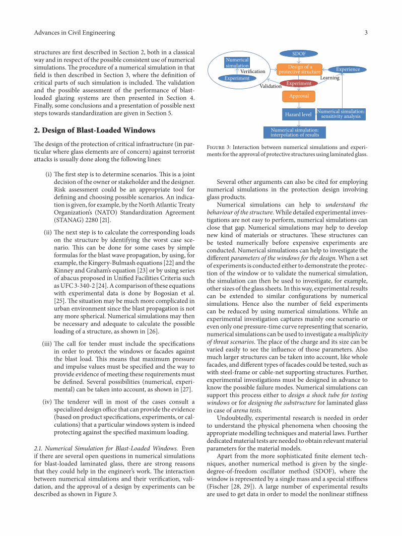
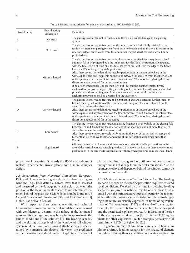
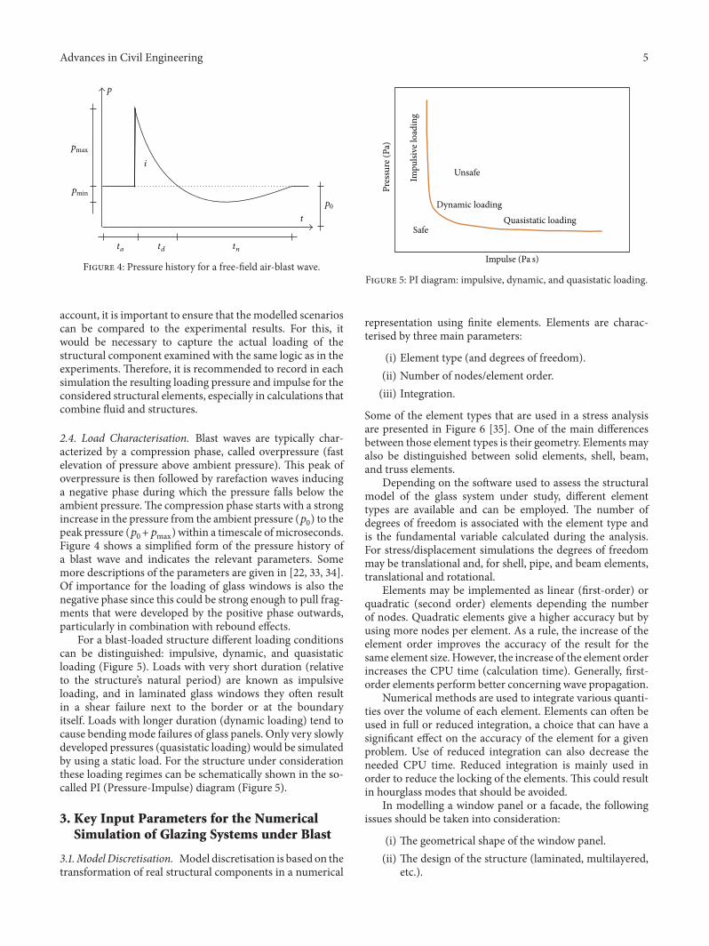
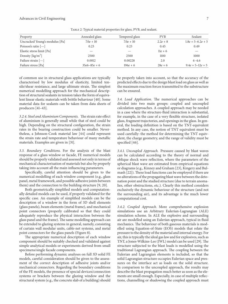
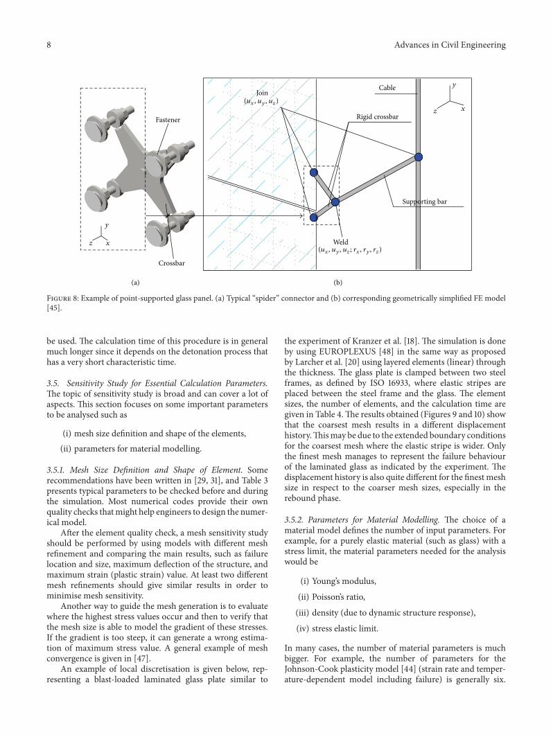
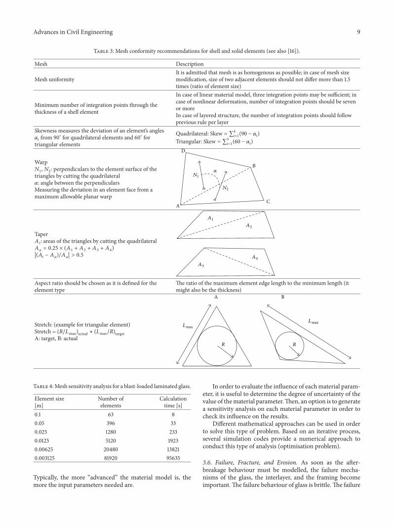
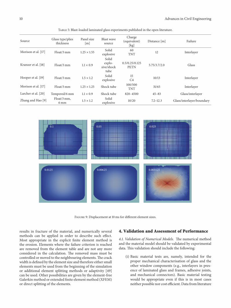
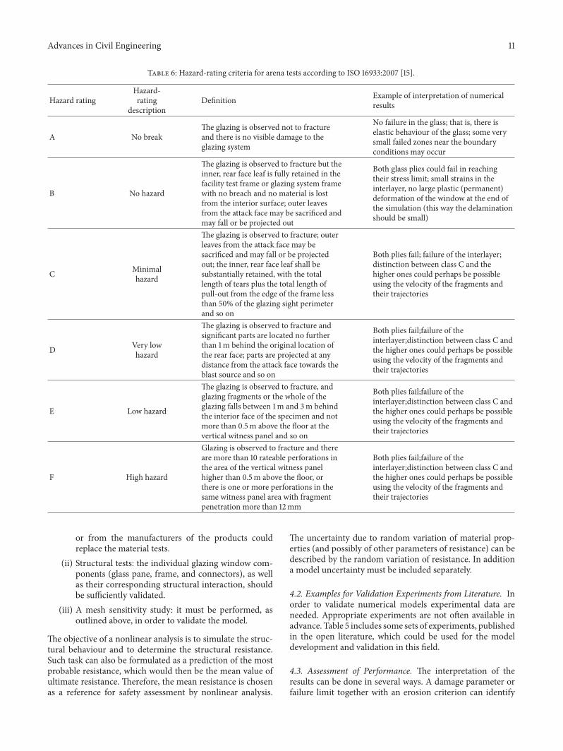
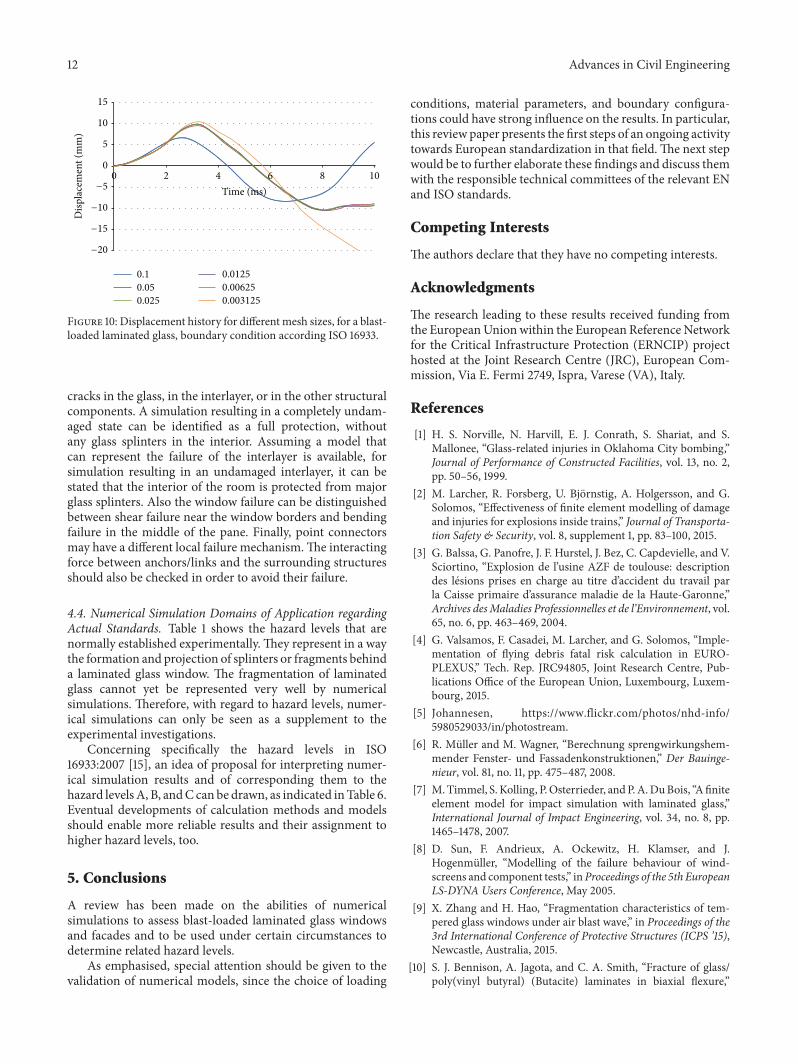
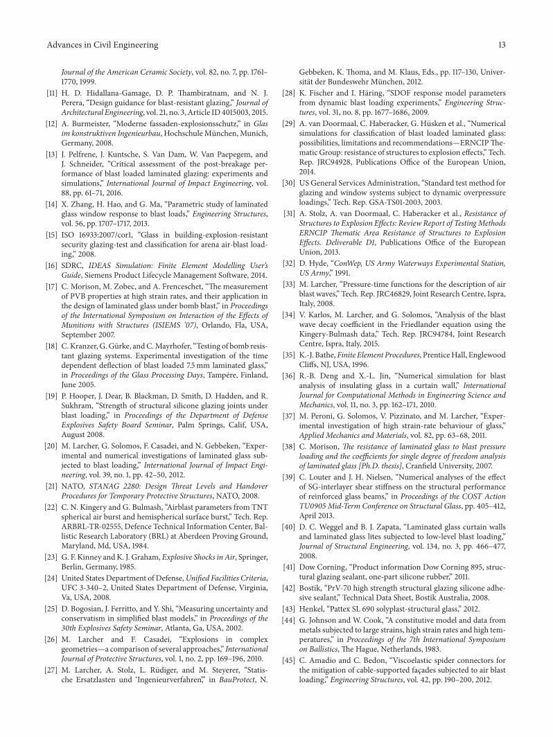

International Journal of
AerospaceEngineeringHindawi Publishing Corporationhttpwwwhindawicom Volume 2014
RoboticsJournal of
Hindawi Publishing Corporationhttpwwwhindawicom Volume 2014
Hindawi Publishing Corporationhttpwwwhindawicom Volume 2014
Active and Passive Electronic Components
Control Scienceand Engineering
Journal of
Hindawi Publishing Corporationhttpwwwhindawicom Volume 2014
International Journal of
RotatingMachinery
Hindawi Publishing Corporationhttpwwwhindawicom Volume 2014
Hindawi Publishing Corporation httpwwwhindawicom
Journal ofEngineeringVolume 2014
Submit your manuscripts athttpwwwhindawicom
VLSI Design
Hindawi Publishing Corporationhttpwwwhindawicom Volume 2014
Hindawi Publishing Corporationhttpwwwhindawicom Volume 2014
Shock and Vibration
Hindawi Publishing Corporationhttpwwwhindawicom Volume 2014
Civil EngineeringAdvances in
Acoustics and VibrationAdvances in
Hindawi Publishing Corporationhttpwwwhindawicom Volume 2014
Hindawi Publishing Corporationhttpwwwhindawicom Volume 2014
Electrical and Computer Engineering
Journal of
Advances inOptoElectronics
Hindawi Publishing Corporation httpwwwhindawicom
Volume 2014
The Scientific World JournalHindawi Publishing Corporation httpwwwhindawicom Volume 2014
SensorsJournal of
Hindawi Publishing Corporationhttpwwwhindawicom Volume 2014
Modelling amp Simulation in EngineeringHindawi Publishing Corporation httpwwwhindawicom Volume 2014
Hindawi Publishing Corporationhttpwwwhindawicom Volume 2014
Chemical EngineeringInternational Journal of Antennas and
Propagation
International Journal of
Hindawi Publishing Corporationhttpwwwhindawicom Volume 2014
Hindawi Publishing Corporationhttpwwwhindawicom Volume 2014
Navigation and Observation
International Journal of
Hindawi Publishing Corporationhttpwwwhindawicom Volume 2014
DistributedSensor Networks
International Journal of