review of drilling, completion and remediation methods for ... · review of drilling, completion...
TRANSCRIPT
Review of Drilling, Completion and Remediation Methods for ASR Wells in Unconsolidated Aquifers Anne-Sophie Segalen1, Paul Pavelic2 and Peter Dillon2 1 Schlumberger Water Services (on secondment to CSIRO Land and Water) 2 CSIRO Land and Water
CSIRO Land and Water Technical Report No. 04/05 March 2005

Copyright and Disclaimer © 2005 CSIRO To the extent permitted by law, all rights are reserved and no part of this publication covered by copyright may be reproduced or copied in any form or by any means except with the written permission of CSIRO Land and Water.
Important Disclaimer: CSIRO Land and Water advises that the information contained in this publication comprises general statements based on scientific research. The reader is advised and needs to be aware that such information may be incomplete or unable to be used in any specific situation. No reliance or actions must therefore be made on that information without seeking prior expert professional, scientific and technical advice. To the extent permitted by law, CSIRO Land and Water (including its employees and consultants) excludes all liability to any person for any consequences, including but not limited to all losses, damages, costs, expenses and any other compensation, arising directly or indirectly from using this publication (in part or in whole) and any information or material contained in it.
Cover Photograph: From Schlumberger Water Services Description: Drilling at Sharjah, U.A.E.
CSIRO Land and Water Page i
Review of Drilling, Completion and Remediation Methods for ASR Wells in Unconsolidated Aquifers
Anne-Sophie Segalen1, Paul Pavelic2 and Peter Dillon2
1 Schlumberger Water Services (on secondment to CSIRO Land and Water) 2 CSIRO Land and Water
Technical Report No. 04/05 March 2005

CSIRO Land and Water Page ii
Executive Summary
This report is a literature review on the effect that alternative drilling techniques, well completion designs, and redevelopment and maintenance methods have in reducing the risk of operational problems for ASR wells in unconsolidated formations, and in particular, their influence on the rate of clogging of these wells. The goal is to find a combination of drilling, completion and maintenance techniques that optimize the productive life of conventional and ASR wells in unconsolidated aquifers.
Although surprisingly few comparative cases studies were found, these revealed that:
• production wells drilled with cable tool significantly outperformed reverse circulation rotary drilled wells in the same formation,
• wells drilled using biodegradable mud gave rise to less clogging than when bentonite-based mud was used in the same formation,
• residual mud on or in the vicinity of the borehole wall severely limited recharge capacity, and reaming of mud-drilled wells prior to completion was highly effective in increasing specific capacity,
• wire-wrapped screens and natural gravel pack completion significantly enhanced well performance compared with slotted casing and emplaced gravel pack in the same formation.
These conclusions demonstrate the importance of the choice of drilling technique, and the quality of the drilling, well completion and design, in very significantly enhancing ASR well performance. Site-specific investigations are required to determine the nature and location of clogging material in order to define protocols to rehabilitate severely clogged injection wells.
Furthermore, research is needed to determine; geological conditions under which reverse-circulation rotary drilling is more effective than standard rotary drilling; the effect of reaming following rotary drilling with biodegradable mud; the effectiveness of dual-wall reverse-circulation drilling; and to assess the potential for clogging and rehabilitation of horizontally drilled ASR wells. There appears to be inadequate data to reliably predict life-cycle costs of ASR wells accounting for rehabilitation.

CSIRO Land and Water Page iii
Table of Contents
Executive Summary ii 1 Introduction 1 2 Drilling Techniques 2
2.1 Cable Tool Method 2 2.2 Direct Rotary Method with Fluids 2 2.3 Direct Rotary: Drill-through Casing Hammer 3 2.4 Reverse-circulation Rotary Method with Fluids 3 2.5 Dual-Wall Reverse Circulation Rotary Method 3 2.6 Jet Drilling 3 2.7 Hydraulic Percussion Method 4 2.8 Driven 4 2.9 Horizontal Drilling 4
3 Drilling Fluids 8 3.1 Drilling fluids for vertical wells 8 3.2 Drilling fluids for horizontal wells 9
4 Completion of Wells 9 4.1 Casing 10 4.2 Screens and Filter Packs 10 4.3 Flow Control 10
5 Managing Clogging of ASR Wells 11 5.1 Well Redevelopment Techniques 11 5.2 Water Quality Effects on Clogging 13
6 Comparative Studies of Well Construction and Completion 13 6.1 Comparison of Reverse-Circulation Rotary and Cable Tool Drilling at Hydron, Netherlands 16 6.2 Comparison of Reamed and Unreamed Rotary Drilled Wells at Amsterdam, Netherlands 17 6.3 Comparison of Borehole Diameters at Berkheide 17 6.4 Comparison of Well Completions at Glendale Arrowhead Ranch Recharge Facility
(Glendale, Arizona) 18 7 Conclusions and Recommendations 19
7.1 Conclusions on Drilling, Completion and Redevelopment Methods. 19 7.2 Recommendations 20
8 Acknowledgements 20 9 References 21

CSIRO Land and Water Page i
List of Tables and Figures Table 2-1: Comparison of Different Drilling Techniques Used in Unconsolidated Aquifers. 6
Table 5-1: Well-Redevelopment Techniques 12
Table 6-1: Case Studies Where Drilling Techniques and Completion Methods were Investigated 14
Table 6-2: Comparison of well performance for the 2001/2002-recharge season of ASR type A and ASR type B (Chaves et al., 2003) 18
Figure 3-1: Reduction of hydraulic conductivity (K) due to drilling fluid coating of the borehole wall 8
Figure 6-1: Difference in clogging rate between wells drilled using cable tool and reverse circulation rotary drilling techniques at Hydron (Timmer et al., 2003) 16
CSIRO Land and Water Page 1
1 Introduction It is generally known that clogging problems can be more severe in unconsolidated aquifers than for injection or ASR wells in consolidated aquifers, where screens or gravel packs are generally not required. This is because the screen/gravel pack restricts the ability to redevelop the well once clogging has occurred. The aim of this research is to evaluate what is currently known about the effects of different drilling techniques, well completion designs, and redevelopment techniques on the performance of ASR wells in unconsolidated formations. The main issue is to avoid excessive clogging that leads to reduced injection rates and increased need to implement unclogging procedures. Other problems can also arise (e.g. excessive sand production). By understanding the impact of the various factors that affect the recharge capacity of ASR wells over the long term, the volumes of water stored and recovered can be maximized, and costs minimized. Unconsolidated formations include dune sands, alluvial deposits of sand and gravel, and unconsolidated marine deposits. The challenges in drilling and completing wells in these types of formations are to keep the borehole open and prevent caving, and to avoid reducing the hydraulic conductivity of the near-well formation by introducing irrecoverable mud or smearing clay at the well/aquifer interface during the drilling process.
Owing to the sparse information on the effects of alternative completion arrangements for ASR wells, conventional water production wells were included in the review. Case studies were sought on:
• operational problems and how these have been resolved;
• comparative studies where different drilling methods or well completion techniques have been used and well yield or rates of clogging observed; and
• innovative borehole design techniques.
Several researchers were contacted and invited to share their information and experience (see acknowledgements).
CSIRO Land and Water Page 2
2 Drilling Techniques
Driscoll (1986), Todd (1960), Walton (1970) and Hancock and MacPherson (1987) describe eight vertical and one horizontal drilling techniques that may be employed in unconsolidated formations. These are summarized below. The advantages and disadvantages of these techniques, their relative penetration rates and an estimation of their “clogging potential” are given in Table 2-1. Table 2-2 provides advantages and disadvantages of horizontal drilling compared to vertical drilling.
Evaluating the importance of clogging and realising that different drilling methods can have an effect on specific capacity of wells is important for ASR wells where a decline in specific can severely limit injection rates and economic viability of ASR projects.
2.1 Cable Tool Method
Wells drilled by the cable tool or ‘wire line’ method are constructed with a drilling rig, a string of tools (cable, rope socket, set of jars, drill stem and drilling bit), and a bailer or a sand pump. Drilling is accomplished by regularly lifting and dropping the string of tools. The bit, at the end of the rope, with its sharp “chisel” edge loosens the material. The bit rotates a few degrees between each stroke so that the cutting face of the bit strikes a different area of the hole-bottom with each stroke. The reciprocating action of the tools mixes the loosened particles with water to form slurry at the bottom of the borehole (water may need to be added to form this slurry). Slurry accumulation increases as drilling proceeds and eventually it reduces the drilling efficiency. When the penetration rate becomes unacceptably low, slurry is removed at intervals from the borehole by the sand pump or bailer.
2.2 Direct Rotary Method with Fluids
Drilling fluid is forced down the inside of a rapidly rotating drill stem and out into the formation through openings in the bit. The drilling mud flows back to the surface, carrying the drill cuttings with it, by way of the annulus formed between the outside of the drill pipe and the hole wall. At the surface, the fluid is channeled into a settling pit where most of the cuttings drop out. Clean fluid is then picked up by the pump at the far end of the pit and is re-circulated down the hole.
No casing is ordinarily required during drilling because the drilling fluid is sufficiently dense and maintained at a pressure that exceeds pore water pressure, which prevents caving. To drill efficiently, the hole size, drill pipe size, bit type, pump capabilities, and drilling fluid characteristics must be properly selected. Drilling fluids include clean water and prepared mixtures of special-purpose materials. The fluid is usually a mixture of water and special viscosity-building additives (various types are described later).
For drilling unconsolidated formations, drag bits (fishtail and three- and six-way designs) can be used. Drag bits, which have short blades, each forged to a cutting edge and faced with a durable metal, have a shearing action and cut rapidly in sands, clays, and some soft rock formations. A tri-cone bit, which is an all-purpose bit, can also be used.

CSIRO Land and Water Page 3
2.3 Direct Rotary: Drill-through Casing Hammer
This technique was developed to combine the hole stability of cable tool rigs with the speed of air rotary rigs. Casing drivers can be fitted on to direct air rotary rigs. Casing can be installed during drilling operations. But both drilling and driving can be adjusted independently depending on the nature of the formation. Drivers are usually designed to also be able to drive upward to remove casing or expose a screen.
To operate this drilling technique, the drill pipe and casing, which are of same length, are usually preassembled as one unit and raised into position on the mast of the drill rig. Similarly to cable tool operations, the bottom of the casing is fitted with a drive shoe. A bit that fits inside the casing is attached to the bottom of the drill pipe. The top of the casing fits in the bottom of the casing driver by means of an anvil. A piston that is activated by air pressure drives the casing.
2.4 Reverse-circulation Rotary Method with Fluids
In reverse-circulation rotary drilling, flow of the drilling fluid is in the opposite direction to the direct rotary method where drilling fluid is forced down the annulus between the drill stem and hole wall and recovered from the drill stem. This reverse type of drilling is a suction dredging method in which the cuttings are removed by a suction pipe. The rig includes a large-capacity centrifugal pump, a drill pipe, and a bit, which resembles a dredge. During drilling, hydrostatic pressure, acting against a film of fine-grained material deposited on the walls by the drilling water, prevents the walls from caving in. Cuttings are removed by water flowing up the pipe. The mixture is circulated through a sump in which the sand settles out, but fine-grained particles are re-circulated back into the hole where they aid in stabilizing the walls.
2.5 Dual-Wall Reverse Circulation Rotary Method
The dual-wall technique uses flush-jointed, double-wall pipe in which the air or liquid drilling fluid moves by reverse-circulation. The drilling fluid is run down between the two walls of the dual-wall pipe and only contacts the walls of the borehole near the bit.
Dual-wall pipe is frequently set by reverse-circulation methods using a top-head drive unit. Down-the-hole air hammers and tri-cone bits can be used to penetrate the formation. Drilling fluids can consist of dry air, air and water, air and water with surfactants, or water with clay or polymers. Surface casing is not needed when using this technique. Screens and casing can also be installed.
2.6 Jet Drilling
A high-velocity stream of water is used to construct the wells. The jet-percussion method is usually limited to drilling 76 to 102 mm diameter wells to depths of about 60 m. A chisel-shaped bit attached to the lower end of a pipe string is used to drill the hole. Holes on each side of the bit serve as nozzles for water jets that keep the bit clean and help loosen the encountered material. Water is pumped under moderate to high pressure through the drill pipe and out the bit. The cuttings are carried up to the surface in the drilling fluid, which flows upward in the annular space around the pipe. The charged fluid is channeled into pits where

CSIRO Land and Water Page 4
the cuttings settle to the bottom. The water is then picked up with a suction pump and re-circulated through the drill pipe.
This method resembles direct rotary drilling by its fluid circulation system, and cable tool drilling by its lifting, dropping and rotation of the drill rod and the bit, but with shorter strokes. Casing, fitted with a drive shoe, is usually sunk as drilling proceeds. Open holes can be drilled to limited depths in unconsolidated materials by this method if a low-viscosity drilling fluid is used. However, casing must be installed that should follow the bit quite closely whenever the uncased hole starts to cave-in or is in zones of high fluid loss.
Another jet drilling method, which uses small diameter pipe and well points with open bottoms that can be sunk in sandy formations by the washing action of a water jet without any drilling tools, can be used.
2.7 Hydraulic Percussion Method
Similarly to the jet-percussion method, this procedure uses a string of drill pipe or drill rod. A ball check valve is provided between the bit and the lower end of the drill pipe. Water is introduced at the surface into the annular space between the drill rods and well casing to keep the hole full of water.
Drilling proceeds by lifting and dropping the drill rods and bit with quick, short strokes. As the bit drops and strikes the bottom, water cuttings in suspension enter the ports of the bit. When the bit is lifted, the check valve closes, thus trapping the fluid inside the drill pipe. Continuous repeated motion produces a pumping action to lift the fluid along with the cuttings to the top of the string of drill pipe where it discharges into a settling tank. Casing is driven as drilling proceeds. Since the cable tool rig does not require a pressure pump, it can be adapted to operate this technique.
2.8 Driven
Driven wells are usually installed in relatively cobble- and boulder-free unconsolidated formations. This method involves driving well points into the ground either by hand or mechanically.
2.9 Horizontal Drilling
Horizontal wells have been constructed for a variety of environmental applications over the past 15 years including: groundwater extraction for pumping and treatment, soil vapor extraction, air sparging, free product recovery, bioventing/bioremediation, other remediation technologies and hydraulic containment. These applications and the following description on horizontal drilling are summarised from Kaback (2002).
Before drilling the design of the horizontal well must be defined. Design criteria for a horizontal well include well screen location (including screen depth and length), screen size (slot size, slot pattern, and diameter), filter pack requirement, screen material, riser casing size and material and borehole path. The choice of drilling equipment and the degree of difficulty in drilling depends on the determination of the borehole path, which involves determining an approach angle, radius of curvature, and step-off distance (i.e. horizontal distance between the entry hole and the beginning of the horizontal section of the borehole.) The step-off distance is often fixed by site-specific conditions.

CSIRO Land and Water Page 5
The drilling technique used depends on the chosen borehole type, which can be continuous (surface to surface) or blind (surface to end of horizontal section). Continuous boreholes have the advantage of duplicate access points and the ability to install longer screen sections. However, if a second site for surface access is not available a blind-installation may have to be utilized. Blind boreholes have the advantage of only one curved section, which is often the most difficult to drill and install. The installation procedures for continuous and blind boreholes are described in detail by Kaback (2002) and Miller (1996).
Drilling curved and horizontal directional boreholes requires specialized drilling equipment. This equipment is contained in a bottom-hole assembly that consists of a drilling tool, a bent sub-assembly, and a guidance tool. The drilling tool is preferentially oriented in the borehole by the bent sub-assembly in order to drill in the desired direction. The guidance tool supplies drilling tool orientation and the azimuth and inclination of the borehole to the driller. There are three types of drilling tools used in directional drilling: down-hole mud motor, jetting tool, and compaction tool. The three types of tools are used in all types of formations, with the compaction tool most commonly used for drilling small boreholes with limited vertical depth (<20m) in unconsolidated formations. Each of these tools are described by Kaback (2002).
The guidance system is located in the bottom-hole assembly behind the drilling tool and the bent sub-assembly. Types of guidance include: a magnetometer-accelerometer system, an inertial (gyroscope) system, or a radio beacon-receiver system. This specialized bottom-hole assemblies are mounted on a directional drilling rig. Directional drilling rigs of any size have a few common characteristics: a capacity for using a fluid while drilling and a method for providing a thrust force to the drill string to compensate for lost weight on the bit when drilling the horizontal section of the borehole.

CSIRO Land and Water Page 6
Table 2-1: Comparison of Different Drilling Techniques Used in Unconsolidated Aquifers.
Drilling Technique Advantages Disadvantages
Relative Penetration
Rate
Clogging Potential* Case Reference**
Cable tool
This method enables accurate sampling of the material being drilled and generally allows sampling of water as encountered.The borehole is stabilized during drilling operation.It is possible to drill in areas where little make-up water exists.The risks of contamination of the constructed wells are minor.It is possible to drill in formations where lost circulation is a problem.Bailing is possible at any time to determine the approximate yield at that depth.
In unconsolidated sand and gravel, the loose material slumps and caves around the bit. Casing should be maintained to near the bottom of the hole to avoid caving.
Very slow x Bergambacht, West Holland
Direct Rotary with fluids
This method provides effective development of water bores.This type of drilling is fast and convenient to operate.Well screens can be set easily as part of the casing installation.Drilling fluid management requires knowledge and experience.
Generally sampling is not accurate and no factual information is available during drilling operation.Continuous operation from commencement of cutting the hole until completion of the hole is essential for efficient and safe work.Special care has to be taken throughout the construction of the water bore to avoid loss of performance through clogging of the aquifer with drilling mud.
Rapid ++Berkheide dunes, South-HollandAmsterdam Dune Area
Rotary + Scraping
Very clean boreholes are drilled+
Berkheide dunes, South-HollandAmsterdam Dune Area
Direct Rotary: drill-through casing hammer
Well-drilling is made possible in unconsolidated materials that may be difficult with cable tool or direct rotary methods.The borehole is stabilized during drilling.Penetration rates are rapid.Lost-circulation problems are eliminated.Formation and water sampling can be accurate.No water-based drilling fluid is required in unconsolidated materials.
Noise of operation.Additional costs.
Very rapid N/A
Reverse Rotary with fluids
This technique is particularly well suited to drilling large-diameter holes in soft, unconsolidated formations.The porosity and permeability of the formation near the borehole are relatively preserved when comparing with other techniques.It is possible to drill quickly and economically large-diameter holes.No casing is needed during the drilling operation.Well screens setting can be easily done as part of the casing installation.There are little opportunities for washouts in the borehole because of the low velocity of the drilling fluid.
The water table should be several feet below ground surface to obtain an effective head differential between well and aquifer.Large water supply is generally necessary.Large mud pits are required.
Rapid xx
Bergambacht, West HollandGlendale, ArizonaPalo Alto Baylands, CaliforniaMannheim, Ontario
Reverse Rotary: Dual Wall
It is possible to obtain continuous representative samples of the formation and water.Aquifer yield can be estimated at many depths in the formation.Problems of lost circulation are either eliminated or considerably reduced.Washout zones are reduced or eliminated.
This technique is limited to rather slim holes (less than 229 to 254 mm) and in depth (approximately 366 to 427 m) in alluvial deposits. Very rapid N/A
Hydraulic Percussion
Accurate samples can be obtained. This system is generally limited to drilling small diameter wells throughclay and sand formations that are
Rapid N/A
JettingJet-percussion drilling is commonly used for drilling in water-bearing sand.
This technique is generally limited to small diameter wells. Rapid N/A
*Qualitative index of clogging, based on the studied cases: compare + with ++ (see Kortleve, 1998) and x with xx (see Timmer et al., 2003) ++ or xx means more clogging than + or x; N/A: Not Available
**Refer to Table 6-1 Selected Case Studies

CSIRO Land and Water Page 7
Table 2-2: Advantages and Disadvantages of Horizontal Drilling compared with Vertical Drilling
Drilling Technique Advantages Disadvantages
Horizontal
Horizontal wells are claimed to be more effective in recovering water than vertical wells where the target aquifer is unconfined with a small saturated thickness or highly heterogenous (Kaback, 2002). Permeability is generally greater in the horizontal, rather than the vertical direction and well-positioned horizontal wells can capitalise on this. This may allow more efficient recovery of groundwater via horizontal wells. Directionally drilled horizontal wells can be installed in areas with subsurface obstructions (e.g., vertical wells, utility lines) and can be used where there are surface obstructions.Sites with vertical fractures and thin aquifers are especially appropriate for horizontal well applications.
Horizontal wells must be considered carefully at some sites where the water table fluctuates greatly. If a horizontal well is installed at such a location, the well may change from saturated to unsaturated conditions.Horizontal wells are generally drilled to limited depths (about 15m) but some horizontal wells drilled up to 60m have been reported. A lack of drilling contractors experienced in horizontal techniques is also reported.The amount of time required to thoroughly clean a horizontal well may be much longer than that required to clean a vertical well. The total length of screen in the horizontal well is often many times greater than that utilized in vertical wells. Physical and chemical methods of treatment are usually recommended to ensure successful development. Recommended actions may include acid wash, water flush, water jet, surge block/suction head, and air lift/overpumping (Kaback, 2002 and Miller 1996).

CSIRO Land and Water Page 8
3 Drilling Fluids
3.1 Drilling fluids for vertical wells
To drill efficiently, consideration of hole size, drill pipe size, bit type, pump capabilities, and drilling fluid characteristics based on the geologic conditions is needed (Driscoll, 1986). Drilling fluids for unconsolidated formations are water-based and generally include clean fresh water, water with clay additives, water with polymeric additives and water with a mixture of clay and polymeric additives. Commonly used drilling fluids fall into two categories: bentonite-based and biodegradable.
Drilling fluids are essentially used to lift the cuttings from the bottom of the hole and to carry them to a settling pit; to support and stabilize the borehole wall, to seal the borehole wall to reduce fluid loss; and to clean the bit, the mud pump and the drill pipe. As drilling proceeds, a film of small particles (clay, silt, or colloids present in the drilling fluid) builds up on the wall of the borehole, which creates a lining. This lining protects the wall from being eroded by the upward-flowing stream of drilling fluids and seals the wall to minimise fluid loss into the formation. Even after thorough surging, remnants of this lining, however, will remain and thus restrict the passage of water into or out of the well. The zone of influence typically extends into the surrounding formation and reduces hydraulic conductivity (K) (Figure 3-1). This can also enhance the rate of clogging (Timmer et al., 2003).
Figure 3-1: Reduction of hydraulic conductivity (K) due to drilling fluid coating of the borehole wall
Biodegradable drilling fluids are thought to cause less clogging than non-degradable fluids such as bentonite. In Holland, biodegradable drilling mud, such as the German brand Antisol®, which has a minimum carboxymethyl cellulose (CMC) content of 98%, is routinely used. Satisfactory results are typically achieved (Timmer, pers. comm.). Under anaerobic conditions, however, rates of biodegradation of Antisol® mud can be low and lead to extended persistence. Under these conditions wells can be treated with oxidising agents such as hydrogen peroxide (H2O2) to accelerate degradation, however this may not necessarily eliminate long-term well clogging. Reports of enhanced bioclogging as a result of the use of biodegradable muds have also been reported in South Holland.
K’ K Unaffected zone: K Affected zone due to the drilling fluid coating of the wall: K’
K’<K

CSIRO Land and Water Page 9
It appears that the choice of the drilling fluid has an impact on clogging rates. Biodegradable mud is recommended, as bentonite-based mud usually leaves a residual that can severely clog wells.
3.2 Drilling fluids for horizontal wells
Different drilling methods use varying amounts of drilling fluids, which impact on the target formation in different ways. For instance, compaction drilling techniques, which require a minimum amount of drilling fluid, may be utilized at some sites but are restricted to particular types of geological formations. In addition, the compaction technique reduces the permeability of the formation in the immediate vicinity of the borehole and complicates well development. Hence this is not recommended for ASR wells.
Fluids for horizontal drilling, like drilling fluids for vertical wells, are based on either bentonite clays or synthetic/natural polymers. Recent technological advances in drilling fluids that have been approved for environmental applications include bentonite fluids with mixed-metal hydroxides or silicates and advanced polymers (Kaback, 2002). Some of the newer polymers have optimum cuttings carrying-capacity and an ability to degrade naturally and rapidly after drilling is completed, thus requiring minimal well development.
Bentonite-based fluids are commonly used below the water table, where well development can ensure cleaning of the borehole. The amount of time and effort required to thoroughly clean a horizontal well may be much greater than that required for a vertical well. Physical and chemical methods of treatment are usually recommended to ensure successful well development.
The specific well development plan must consider the type of drilling fluid, the horizontal well materials installed in the ground, and the site geology. If a bentonite-based fluid was utilized for drilling, the development should be conducted as soon as possible after drilling is completed. Recommended actions may include acid wash, water flush, water jet, surge block/suction head, and air lift/overpumping.
4 Completion of Wells A complete description on well completion is given by Driscoll (1986), who describes well screens and well design (casing diameter and material; well depth; screen length, slot openings and diameters, and filter pack designs). Kaback (2002) and Miller (1996) describe the completion of horizontal wells.
This section focuses on the selected case studies and the choices made to complete wells in unconsolidated formations (See Table 6-1 on the selected study cases).

CSIRO Land and Water Page 10
4.1 Casing
In the selected cases, corrosion resistant materials were chosen for casings. When specified, either PVC or stainless steel casings were installed. In the Palo Alto project (Sheahan, 1977), double PVC casing was used. Fiberglass-reinforced casing has not been used in the studies even though this type of casing is resistant to most forms of corrosion and has the strength of steel. Steel casings should be avoided, as this material can act as nutrient for biological growth.
4.2 Screens and Filter Packs
In the studied cases, wells are usually completed with filter packs, which are either artificial or natural.
Screens are made of the same corrosion resistant materials as the casing: PVC or stainless steel. When well designs were more precisely described, stainless steel screens had bridge slots or were wire-wrapped, and PVC screens had vertical slots. Slotted steel casing was used in the Glendale project. In the Palo Alto case, double, stainless steel, wire-wound, “keystone” type screens were installed. To prevent excessive deteriorations in well performance, Pérez-Paricio (1998a) advises that wire-wrapped stainless steel screens be used.
The screen size generally ranges from 0.8 to 1 mm. Screen size selection according to the grain size distribution of the aquifer is thoroughly described by Driscoll (1986). The importance of studying the size of the slots is emphasized by experience in Belgium for sandy aquifers (Emmanuel Van Houtte, pers. comm). Van Houtte reports that for Belgian wells completed with PVC casings and 1 mm screens that have been operational since 1981, no maintenance has been required. Conversely, wells completed with PVC casings and 0.5 mm screens need annual maintenance. Both types of wells were drilled in unconsolidated formations and pump similar types of water (rich in iron). The clogging of the wells with the smaller screens is most likely to be due to the precipitation of iron which thus reduces the effective surface area of the screen.
4.3 Flow Control
The Mannheim ASR well (Wooton et al., 1997) was designed to permit the direct injection of treated surface water into the aquifer at a controlled rate. The objective of this design was to prevent cascading of the water into the well and air-entrainment. The design consisted of a 100 hp submersible pump (installed below the well screen) and a Baski Flow Control ValveTM, which were connected to the surface by an epoxy-coated pump column. Well testing showed that this design was effective in providing high, short term well yields by maximizing available drawdown in the well.
Other options to prevent cascading, such as crimping the bottom of the pipe, can also be used. In unconfined formations, gravel pack aeration is done to avoid air-entrainment.

CSIRO Land and Water Page 11
5 Managing Clogging of ASR Wells
Olsthoorn (1982) and Pérez-Paricio (1998a) give precise descriptions on the different causes of well clogging, which are:
• physical clogging due to suspended particles [colloidal particles (diameter < 1µm), “intermediate” particles (1µm < diameter < 30µm) and “large” particles (diameter > 30µm)]
• biological clogging due to bacterial growth
• chemical clogging due to mineral precipitation
• air entrainment and gas binding
• compaction
In the selected cases (see Table 6-1), high quality water is injected into the wells. When clogging is encountered mechanical methods, such as daily or regular pumping, backflushing, purging and air surging, are used to redevelop the well and restore recharge rates.
5.1 Well Redevelopment Techniques
Techniques to prevent clogging and to redevelop clogged wells are described by Olsthoorn (1982), Cullimore (1993), Pérez-Paricio (1998a) and Timmer et al., (2003). Table 5-1 lists different types of redevelopment techniques (mechanical, physical and chemical techniques), which are cited by those authors.
According to Pérez-Paricio (2001), the most preferable technique to redevelop clogged wells is chemical redevelopment by combining hydraulic methods, such as pumping, surging and juttering, and:
• polyphosphates to reduce physical clogging by reducing the stability of retained particles, which enhances the efficiency of detachment.
• chemical oxidants, such as chlorine and hydrogen peroxide, to reduce bioclogging and inactivate bacterial growth.
• acids to reduce chemical clogging by removing mineral encrustations.

CSIRO Land and Water Page 12
Table 5-1: Well-Redevelopment Techniques
Redevelopment Techniques
Backflushing (pumping)
Intermittent pumping
Juttering
Overpumping
Surging
Sectional pumping
Backwashing tubes connected to the screen or gravel pack
Juttering with compressed air, airlifting
Water jetting
Air jetting
Hydrodynamic fracturing
Scraping blades and removal of previously injected muddy water
Dry ice
Brushing
High-frequency vibration
Mechanical Techniques
Regularly switching “on” and “off” submersible pumps
Pasteurization
Disruption by freezing+pumping
Ionizing radiation: gamma radiation Physical Techniques
Explosives and ultrasonic technology
Chlorine and chlorine containing agents (chlorine-bleaching liquor and calcium hypochlorite)
Acids (hydrochloric acid, sulphamic acid)
First chlorine then acid
Polyphosphates (crystalline and glassy polyphosphates)
Carbon dioxide
Chemical Techniques *
High pressure water jet + hydrogen peroxide + hydrochloric acid Enlargement of well diameter
* introduction of chemicals to reinforce mechanical redevelopment

CSIRO Land and Water Page 13
Well-redevelopment strategies, such as ASCE 1993, which combines the action of polyphosphates, jetting, surging and pumping - Blended Chemical Heat Treatment (Cullimore, 1993), and UABTM, which is a three phase chemical process also combined with heat to remove biofilm growth (Lebedin and Cullimore, 2003), are used to manage clogging.
Recent Dutch studies are also to be published (Timmer, pers comm), which show the effectiveness of regular brief activation of submersible pumps to control clogging. This method is also thought to be effective in saving total energy requirements for ASR wells.
A new rehabilitation technique has been developed in Bergambacht (Timmer et al., 2003) and consists in introducing a mixture of 30L of hydrogen peroxide (35%) and 1L of hydrochloric acid at one metre intervals over the screen length by means of a high-pressure water jet (200 bar, 20 L/min) and to enlarge borehole diameters. This new process seems to be more successful over the longer term than traditional methods.
5.2 Water Quality Effects on Clogging
Pérez-Paricio et al., (1998b) recommend numerical guidelines on total suspended solids, turbidity and total organic carbon of source water for injection to minimize clogging risks.
Other measures of water quality parameters can also be used to identify the clogging risk associated with a particular source water. Two examples include the Membrane Filtration Index (MFI) to assess physical clogging (Dillon et al., 2001) and assimilable organic carbon (AOC) for biological clogging (Hijnen et al., 1998). Parameters such as Sodium Adsorption Ratio (SAR), pH, nutrients and metals may offer useful indicators in some circumstances (Rinck-Pfeiffer et al., 2000).
Since the clogging potential of a source water is highly dependent on the physical and chemical characteristics of the target formation, the guidelines only represent an indicative starting point to prevent clogging. Pilot tests are however unavoidable to estimate clogging accurately.
6 Comparative Studies of Well Construction and Completion
Table 6-1 presents a compilation of case studies where the effects of drilling and completion methods in unconsolidated formations on well performance during injection or extraction have been investigated. Unless otherwise stated, wells are water production wells. This chapter expands on the drilling techniques, where known, for the case studies presented in Table 6-1. It gives specifications on the technique used in the Berkheide case study; the study in Bergambacht, which compares reverse-circulation rotary drilling and cable tool drilling; the Glendale experience using reverse-circulation drilling; and a list of the techniques used in the other cases reviewed.
CSIRO Land and Water Page 14
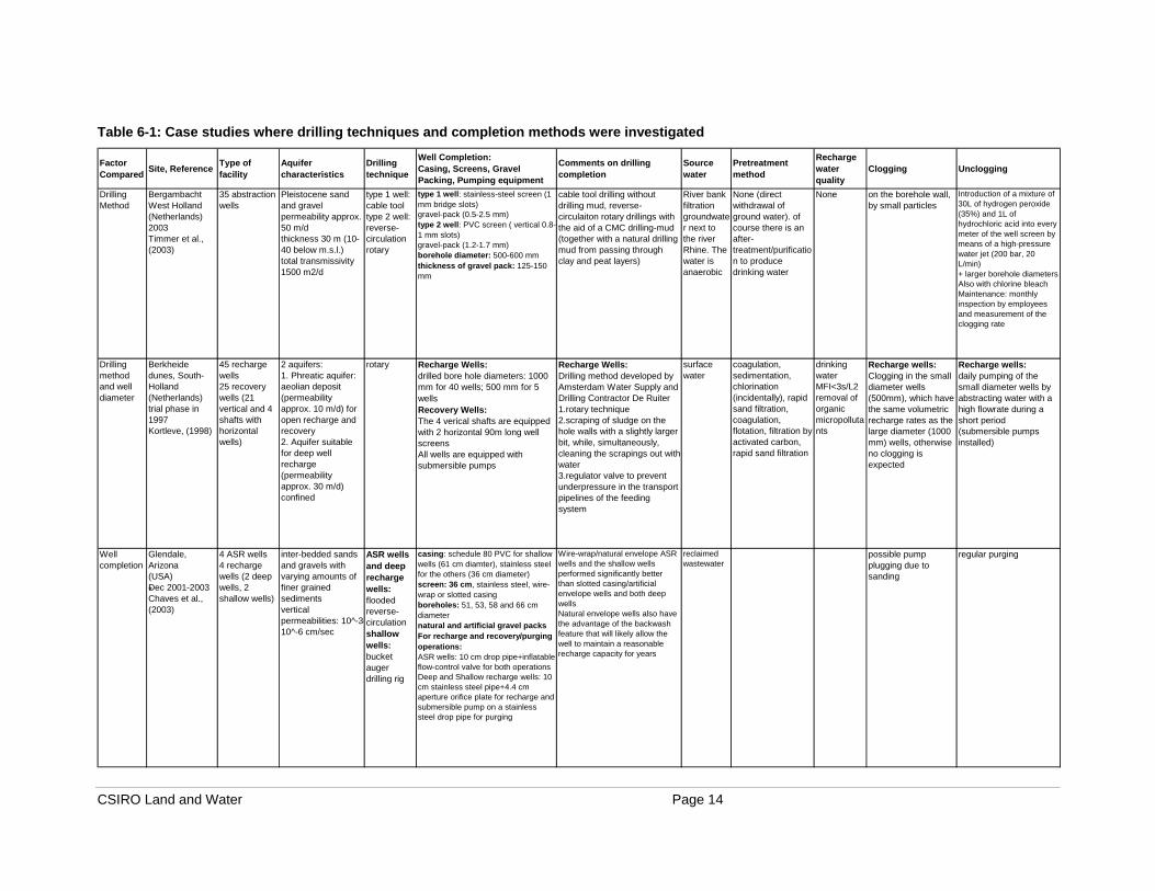
Table 6-1: Case studies where drilling techniques and completion methods were investigated
Factor Compared Site, Reference Type of
facilityAquifer characteristics
Drillingtechnique
Well Completion:Casing, Screens, Gravel Packing, Pumping equipment
Comments on drilling completion
Sourcewater
Pretreatment method
Recharge water quality
Clogging Unclogging
Drilling Method
Bergambacht West Holland(Netherlands)2003 Timmer et al., (2003)
35 abstraction wells
Pleistocene sand and gravelpermeability approx. 50 m/dthickness 30 m (10-40 below m.s.l.)total transmissivity 1500 m2/d
type 1 well: cable tooltype 2 well: reverse-circulation rotary
type 1 well: stainless-steel screen (1 mm bridge slots)gravel-pack (0.5-2.5 mm)type 2 well: PVC screen ( vertical 0.8-1 mm slots)gravel-pack (1.2-1.7 mm)borehole diameter: 500-600 mmthickness of gravel pack: 125-150 mm
cable tool drilling without drilling mud, reverse-circulaiton rotary drillings with the aid of a CMC drilling-mud (together with a natural drilling mud from passing through clay and peat layers)
River bank filtration groundwater next to the river Rhine. The water is anaerobic
None (direct withdrawal of ground water). of course there is an after-treatment/purification to produce drinking water
None on the borehole wall, by small particles
Introduction of a mixture of 30L of hydrogen peroxide (35%) and 1L of hydrochloric acid into every meter of the well screen by means of a high-pressure water jet (200 bar, 20 L/min)+ larger borehole diametersAlso with chlorine bleachMaintenance: monthly inspection by employees and measurement of the clogging rate
Drilling method and well diameter
Berkheide dunes, South-Holland(Netherlands)trial phase in 1997 Kortleve, (1998)
45 recharge wells25 recovery wells (21 vertical and 4 shafts with horizontal wells)
2 aquifers:1. Phreatic aquifer: aeolian deposit (permeability approx. 10 m/d) for open recharge and recovery2. Aquifer suitable for deep well recharge (permeability approx. 30 m/d)confined
rotary Recharge Wells:drilled bore hole diameters: 1000 mm for 40 wells; 500 mm for 5 wellsRecovery Wells:The 4 verical shafts are equipped with 2 horizontal 90m long well screensAll wells are equipped with submersible pumps
Recharge Wells:Drilling method developed by Amsterdam Water Supply and Drilling Contractor De Ruiter1.rotary technique2.scraping of sludge on the hole walls with a slightly larger bit, while, simultaneously, cleaning the scrapings out with water3.regulator valve to prevent underpressure in the transport pipelines of the feeding system
surface water
coagulation, sedimentation, chlorination (incidentally), rapid sand filtration, coagulation, flotation, filtration by activated carbon, rapid sand filtration
drinking waterMFI<3s/L2removal of organic micropollutants
Recharge wells:Clogging in the small diameter wells (500mm), which have the same volumetric recharge rates as the large diameter (1000 mm) wells, otherwise no clogging is expected
Recharge wells:daily pumping of the small diameter wells by abstracting water with a high flowrate during a short period (submersible pumps installed)
Well completion
Glendale, Arizona(USA)Dec 2001-2003 Chaves et al., (2003)
4 ASR wells4 recharge wells (2 deep wells, 2 shallow wells)
inter-bedded sands and gravels with varying amounts of finer grained sedimentsvertical permeabilities: 10^-3-10^-6 cm/sec
ASR wells and deep recharge wells: flooded reverse-circulationshallow wells: bucket auger drilling rig
casing: schedule 80 PVC for shallow wells (61 cm diamter), stainless steel for the others (36 cm diameter)screen: 36 cm, stainless steel, wire-wrap or slotted casingboreholes: 51, 53, 58 and 66 cm diameternatural and artificial gravel packsFor recharge and recovery/purging operations:ASR wells: 10 cm drop pipe+inflatable flow-control valve for both operationsDeep and Shallow recharge wells: 10 cm stainless steel pipe+4.4 cm aperture orifice plate for recharge and submersible pump on a stainless steel drop pipe for purging
Wire-wrap/natural envelope ASR wells and the shallow wells performed significantly better than slotted casing/artificial envelope wells and both deep wellsNatural envelope wells also have the advantage of the backwash feature that will likely allow the well to maintain a reasonable recharge capacity for years
reclaimed wastewater
possible pump plugging due to sanding
regular purging
*

CSIRO Land and Water Page 15
Table 6-1: continued
Factor Compared Site, Reference Type of facility Aquifer
characteristicsDrillingtechnique
Well Completion:Casing, Screens, Gravel Packing, Pumping equipment
Comments on drilling completion
Sourcewater
Pretreatment method
Recharge water quality Clogging Unclogging
NA Mannheim, Ontario (Canada)Jan 1996-July 1998 Wooton et al., (1997)
1 ASR well semi-confined sand and gravelT=5500 m2/day
reverse circulation
casing: 442 mm O.D., PVCscreen: 406 mm O.D., 35 slot, stainless steelsump: stainless steel (to permit positioning of the pump below the well screen)silica sand packbentonite seal on top of sand packbentonite/cement grout filling up the the remainder of the borehole annulussurface casing: 660 mm, steel, to a depth of 6m100-hp submersible pump (installed below the well screen)Baski Flow Control Valve
treated surface water
clogging possibly due to air binding rather than particulates
backflushing
NA Amsterdam Dune Area(Netherlands)1994-2001 Van Duijvenbode and Olsthoorn, (2002)
pilot: 4 injection wells
semi confined 30-60 m below m.s.l.
Amsterdam Water Supply (see above)
Screens, Gravel packTo reduce bacterial growth, infiltration rate at the bore hole wall=0.20m/h (no chlorine)
water from the Rhine
coagulation, rapid sand filtration, embedded sand filter before injection
suitable for injection
Accumulation of biomass and iron flocs in the gravel pack and screen slots
Backflushing removes most of this clogging. Residual clogging removed by air surging
NA North-Holland, Castrican(Netherlands)1990-1994 Stakelbook et al. (1996)
20 infiltration wells12 abstraction wells
sandy, semi-confined automatic control valve to compensate the increase of clogging resistance of each infiltration well in order to maintain the flow rate at a constant level
canal water suitable for injection
Clogging rate for the Infiltration wells: 10 cm in 4 years
Intensive pre-purification of the infiltration water. Backflushing removes most of this clogging. Abstraction wells aren't expected to have ant clogging problems
NA DIZON pilot(Netherlands)1996-1999 Stuyfzand et al., (2002)
1 injection well1 pumping well
upper miocene sands, confinedtotal transmissivity 510 m2/dayhorizontal permeability of the main strata: 4-25 m/day
canal water a.o., coagulation, active carbon filtration, slow sand filtration
suitable for injection
Accumulation of iron flocs and organic matter
Mechanical redevelopment approximately twice per year
NA Palo Alto Baylands, California(USA)July 1978-May 1981 Sheahan, (1977)
1 doublet: injection well and extraction well(objective: create a seawater intrusion barrier)
3 sand and gravel aquifers:6m aquifer, T=43.4 m2/day14m aquifer, T=108 m2/day (leaky artesian)56m aquifer, average T=78.1 m2/day (confined, artesian)
reverse circulation
Double-cased, double-screened, cement grout seperating the 6m and 14m aquifers.14m aquifer: 20.3 cm casing and screening6m aquifer: 15.2 cm casing and screeningCasing: schedule 80 PVCScreen: stainless steel, wire-wound, keystone typeDrilled hole: 61
Reverse-circulation was chosen because this technique does not require drilling fluid additives, such as bentonite, which may seal the water producing formation.
tertiary treated sewage effluent
lime clarification, air stripping, recarbonation, ozonation, filtration, activated carbon adsorption, chlorination
study focused on Cl, NH3, TOC, DOC and 5 halogenated organics
unidentified clogging caused 40% decline in recharge rates over 2.5 years
redevelopment required

CSIRO Land and Water Page 16
6.1 Comparison of Reverse-Circulation Rotary and Cable Tool Drilling at Hydron, Netherlands
Recently a study was conducted by Timmer et al., (2003) on the clogging of conventional wells that pump anaerobic groundwater from an aquifer composed of sandy, fluvial sediments. This study shows that the clogging rate for 15 wells drilled using the cable tool technique is significantly lower than for 7 wells drilled using the reverse-circulation rotary technique. The well field is arranged in a straight line along a distance of 500-1000 m adjacent to the River Rhine. The first set of wells were drilled using cable tool in 1968; the second set were drilled using reverse-circulation rotary drilling in between the first ones. Clogging rate data are presented in Figure 6-1, in terms of the percentage change in specific capacity relative to the original value versus the average cumulative amount of water discharged from each well. The average original specific capacity of cable tool wells was only 3% higher than the average original specific capacity of the reverse-circulation drilled wells. The average specific capacity of the cable tool wells was approximately double that of reverse circulation wells after the first 0.25 million m3 of extraction. The stabilization of the curves for the wells drilled by reverse circulation rotary at 40% of the original capacity is the result of frequent rehabilitation.
Figure 6-1: Difference in clogging rate between wells drilled using cable tool and reverse circulation rotary drilling techniques at Hydron (Timmer et al., 2003) According to Timmer et al., (2003) clogging could be explained by a combination of two processes. The first process relates to the actual drilling of the well, which results in the formation of an initial barrier around the face of the borehole. Organic material and clay particles, present in the drilling fluid used in reverse-circulation rotary drilling, coat the borehole wall and migrate into the aquifer formation. Even after well completion and thorough surging, some of this material will remain in the pore spaces and restrict the passage of water, thus creating the initial barrier. Such a barrier may also be formed when using the
0%
20%
40%
60%
80%
100%
120%
0.0 0.5 1.0 1.5 2.0 2.5 3.0Discharged amount individual well (million m3), all wells pumping at
80 m3/h
Spec
ific
capa
city
as
perc
enta
ge o
f ori
gina
l spe
cific
ca
paci
ty (%
)
cable tool method, average of 15 wells
reverse circulation rotary drilling, average of 7 wells

CSIRO Land and Water Page 17
cable tool drilling method. This happens during the introduction of casing, which can scrape the borehole. This disturbs the original packing of the aquifer material around the borehole wall. These initial barriers can enhance clogging. The second process is the increase in pore water velocity and the transport of particles caused by converging flow paths toward the well, which favors clogging in the immediate vicinity of the well.
This case study shows that the actual drilling technique has an influence on well performance and clogging rates. Less clogging was observed during the first seven years when cable tool drilling was used. In seven years, the specific capacity drops to a 40% level (average use 80 m3/h, 12 hours a day, 365 days a year). After reaching 40% of the initial specific capacity, these wells need rehabilitation every 2-3 years. Conversely, in the first seven years, the reverse-circulation drilled wells needed rehabilitation every 2 years. On the one hand, cable tool drilled wells therefore saved the cost of two rehabilitations compared to the reverse-circulation rotary-drilled wells. On the other hand, cable tool drilling is considerably more expensive than reverse-circulation rotary drilling. Therefore reverse-circulation rotary drilling could be economically justified even if more maintenance would be needed. Cable tool drilling would be preferred from a technical viewpoint, whilst from an economic viewpoint reverse-circulation rotary drilling may be preferred.
6.2 Comparison of Reamed and Unreamed Rotary Drilled Wells at Amsterdam, Netherlands
The Amsterdam Water Supply and the drilling contractor De Ruiter developed a new drilling method in 1993 for the construction of injection wells (Kortleve, 1998). This method consists of two steps. Firstly, the injection well is drilled using standard rotary drilling. During the drilling procedure a thin layer of sludge coats the drill hole. Secondly, a slightly larger drilling bit is introduced into the hole to scrape off this layer of sludge from the drill hole wall. At the same time clean water is run down the hole. The water containing the scrapings in suspension is then recovered.
This method was shown to be effective in drilling the “Berkheide well recharge system” in the Netherlands. During the scraping, the recharge rate of the drill hole increased from 25 m3/h to 400 m3/h for an unchanged pressure differential (Kortleve, 1998). Therefore reaming the borehole enhanced the recharge rate by a factor of 16. This study shows that rotary drilling followed by borehole reaming may be a valuable technique to minimize clogging in ASR wells.
6.3 Comparison of Borehole Diameters at Berkheide
In the study at Berkheide (Kortleve, 1998), two sizes of well, operating under identical conditions, are compared. Forty wells designed with a borehole diameter of 1000 mm, and five wells, which have borehole diameters of 500 mm, were recharged at the same volumetric flow rate. The entrance velocity was therefore twice as great for the 500 mm diameter wells and clogging was expected to occur more rapidly. To prevent this, these five wells were redeveloped by pumping at a higher flow-rate for a short period of time on a daily basis. To the authors’ knowledge, the results of this operational procedure have not been reported.
The Dutch research project on clogging in Bergambacht (Timmer et al., 2003) proposes new rehabilitation procedures, which are reported in section 5, for wells that have clogged significantly. An adaptation of the standard construction of wells is also proposed to complete the new rehabilitation strategy. The enlargement from 600 mm to 1000 mm of the standard
CSIRO Land and Water Page 18
diameters is thought to provide effective results because larger surface area of the borehole wall takes longer to clog, and the larger diameter also reduces groundwater velocity at the wall and the amount of fines that may be mobilized. Olsthoorn (1982) recommends drilling wells to a diameter that optimises the redevelopment of the well (e.g. with compressed air) when it is needed.
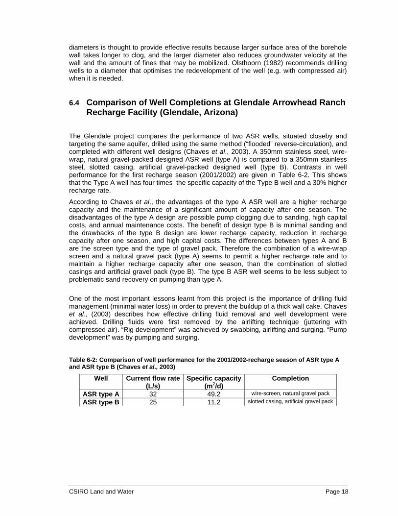
6.4 Comparison of Well Completions at Glendale Arrowhead Ranch Recharge Facility (Glendale, Arizona)
The Glendale project compares the performance of two ASR wells, situated closeby and targeting the same aquifer, drilled using the same method (“flooded” reverse-circulation), and completed with different well designs (Chaves et al., 2003). A 350mm stainless steel, wire-wrap, natural gravel-packed designed ASR well (type A) is compared to a 350mm stainless steel, slotted casing, artificial gravel-packed designed well (type B). Contrasts in well performance for the first recharge season (2001/2002) are given in Table 6-2. This shows that the Type A well has four times the specific capacity of the Type B well and a 30% higher recharge rate.
According to Chaves et al., the advantages of the type A ASR well are a higher recharge capacity and the maintenance of a significant amount of capacity after one season. The disadvantages of the type A design are possible pump clogging due to sanding, high capital costs, and annual maintenance costs. The benefit of design type B is minimal sanding and the drawbacks of the type B design are lower recharge capacity, reduction in recharge capacity after one season, and high capital costs. The differences between types A and B are the screen type and the type of gravel pack. Therefore the combination of a wire-wrap screen and a natural gravel pack (type A) seems to permit a higher recharge rate and to maintain a higher recharge capacity after one season, than the combination of slotted casings and artificial gravel pack (type B). The type B ASR well seems to be less subject to problematic sand recovery on pumping than type A.
One of the most important lessons learnt from this project is the importance of drilling fluid management (minimal water loss) in order to prevent the buildup of a thick wall cake. Chaves et al., (2003) describes how effective drilling fluid removal and well development were achieved. Drilling fluids were first removed by the airlifting technique (juttering with compressed air). “Rig development” was achieved by swabbing, airlifting and surging. “Pump development” was by pumping and surging.
Table 6-2: Comparison of well performance for the 2001/2002-recharge season of ASR type A and ASR type B (Chaves et al., 2003)
Well Current flow rate (L/s)
Specific capacity(m2/d)
Completion
ASR type A 32 49.2 wire-screen, natural gravel pack
ASR type B 25 11.2 slotted casing, artificial gravel pack

CSIRO Land and Water Page 19
7 Conclusions and Recommendations
7.1 Conclusions on Drilling, Completion and Redevelopment Methods.
This report is based on a review of the literature on the influence of different drilling techniques, well completion designs, well redevelopment and maintenance methods to reduce operational problems for conventional and ASR wells completed in unconsolidated aquifers. Several researchers were contacted directly to seek literature and their personal knowledge on the subject. The very few case studies that were found provided valuable information. The following conclusions stand out and are developed in the next paragraphs:
• both the drilling technique and the procedures employed during drilling have an influence on well performance
• removal of residual mud from the borehole is required to minimize clogging problems and to maximize well efficiency. Biodegradable muds are preferred to bentonite muds for this reason.
• careful consideration of the well completion and design, and particularly on the type of screen can significantly increase ASR well performance
• investigations are important to determine the nature and location of clogging material in order to define a specific protocol to redevelop severely clogged wells
According to this literature review, and in particular the comparison of the different drilling techniques and the Dutch experiences, three effective drilling techniques stand out: cable tool, rotary with biodegradable mud, and reverse-circulation rotary.
The Bergambacht case study that compares clogging rates between cable tool and reverse-circulation rotary drilled wells (in the same unconsolidated formation) clearly shows that the cable tool drilling technique is the most preferable, with a two-fold difference in well performance.
The cable tool method is however very slow compared to the rotary or the reverse-circulation rotary methods. Drilling using the cable tool technique is also difficult when boulders or hard rock is encountered.
The effect of reaming after rotary drilling, appears to warrant closer attention. The only related information, known as the Amsterdam Water Supply technique (rotary drilling followed by a scraping of the borehole wall), showed a 16 fold increase in recharge rate for an unchanged pressure differential compared to the case where no scraping was performed. Enlarging the well diameter is also thought to reduce the rate of clogging.
No significant cases or literature have been found that compare clogging rates between rotary drilled wells and reverse-circulation rotary drilled wells. However rotary drilling by an experienced driller using biodegradable mud seems to be preferable to reverse-circulation, because accurate samples can be obtained and the drilling procedure can be better controlled.
The main disadvantage of reverse-circulation rotary drilling is the layer of sludge, which coats the borehole wall and initiates clogging. Dual-wall reverse-circulation drilling, which only allows the drilling fluid to be in contact with the wall at the bit, may be an alternative technique to rotary drilling with biodegradable mud. The penetration rate of this drilling technique is reported to be even higher than for rotary drilling with fluids.

CSIRO Land and Water Page 20
The Glendale case study suggests a major advantage in completing ASR wells with wire-wrap screens and natural gravel packs over slotted casing and artificial gravel packs.
Mechanical techniques, such as purging, backflushing and regular pumping, at times in conjunction with chemical treatments, are mostly used to maintain and redevelop wells. Juttering with compressed air is recommended by Olsthoorn (1982). In the Bergambacht case study, the clogging material was thoroughly analysed which enabled the identification of a precise chemical treatment procedure to successfully unclog the wells. No literature was found which recommended techniques particular to unconsolidated formations.
7.2 Recommendations
The gaps in knowledge identified by this review suggest that field-based research is needed to:
• compare reverse-circulation rotary and standard rotary drilling,
• determine the effect of reaming using rotary drilling with biodegradable mud,
• determine the effectiveness of dual-wall reverse-circulation drilling,
• assess the effect of the aquifer characteristics (particularly hydraulic conductivity) on the effectiveness of the drilling technique and the completion of the well,
• determine the feasibility and effectiveness of horizontal drilling for ASR, and
• evaluate protocols for well redevelopment to optimise cost effectiveness of ASR well performance.
Without further investigations, an accurate estimation of the final costs and life expectancy of the wells (clogging rates) cannot be made.
8 Acknowledgements
This literature review forms part of a collaborative project between Schlumberger Water Services and CSIRO Land and Water to investigate ASR in unconsolidated formations. The authors are indebted to Dominic McCann, Schlumberger Water Services, for initiating the lead author’s secondment to CSIRO that enabled this work to be undertaken.
The valuable information provided by Harrie Timmer (Hydron, South Holland) and Russell Fletcher (City of Glendale, Arizona, USA) is gratefully acknowledged.
Emmanuel Van Houtte (Intermunicipal Water Company of the Veurne Region I.W.V.A., Belgium), Gideon Tredoux (CSIR, South Africa) and Des Yin Foo (Department of Infrastructure Planning and Environment, NT, Australia) are also acknowledged for their helpful advice.

CSIRO Land and Water Page 21
9 References
Chaves, J.S., Greenslade, W.M., Grubbs, W.L. and Fletcher, R. (2003) Glendale Arrowhead Ranch Recharge Facility Glendale, Arizona. Paper presented at the 11th Biennial Symposium on Groundwater Recharge, Phoenix, AZ, June 5-7, 2003.
Cullimore, D.R. (1993) Practical Manual of Groundwater Microbiology, Lewis Publishers.
Dillon, P.J. and Pavelic, P. (1996). Guidelines on the quality of stormwater and treated wastewater for injection into aquifers for storage and reuse. Urban Water Research Association of Australia Report 109, Centre for Groundwater Studies Report No 63A.
Dillon, P.J., Pavelic, P., Massman, G., Barry, K. and Correll, R. (2001) Enhancement of the membrane filtration index (MFI) method for determining the clogging potential of turbid urban stormwater and reclaimed water used for aquifer storage and recovery. Desalination 140:153-165.
Driscoll, F.G. (1986) Groundwater and Wells, Second Edition, Johnson Filtration Systems Inc.
Hancock, R.R. and Macpherson, D.A. (1987) Well Drilling Workshop Course 526/87, 9th Groundwater School, Volume 2A (23rd August-4th September, 1987) Centre for Groundwater Studies.
Hijnen, W.A.M., Bunnick, J. and Schippers, J.C. (1998) Determination the clogging potential of water used for artificial recharge in deep sandy aquifers. In: Artificial Recharge of Groundwater, Peters et al. (Eds.) Proceedings of the 3rd International Symposium on Artificial Recharge of Groundwater (TISAR’98), Amsterdam, Sept. 21-25, 1998, A.A. Balkema, Rotterdam, ISBN. 90 5809 017 5, pp. 437-440.
Kaback, D. (2002) Technology Status Report: A Catalogue of the Horizontal Environmental Wells in the United States. Technology Status Report (TS-02-01) GWRTAC SERIES (27/07/2004: http://www.gwrtac.org/pdf/hor-wells.pdf )
Kortleve, M.W. (1998) Berkheide well recharge system: Design, implementation and initial experience of operation. In: Artificial Recharge of Groundwater, Peters et al. (Eds.) Proceedings of the 3rd International Symposium on Artificial Recharge of Groundwater (TISAR’98), Amsterdam, Sept. 21-25, 1998, A.A. Balkema, Rotterdam, ISBN. 90 5809 017 5, pp. 319-324.
Lebedin,J. and Cullimore,R.(2003) City of North Battleford Well 15 1997 Field Test of UABTM Treatment Technology, PFRA-Droycon North Battleford Water Well Rehabilitation Final Report.
Miller, P.G.R.R. (1996) Horizontal Wells. Technology Overview Report (TO-96-02) GWRTAC SERIES. (27/07/2004: http://www.gwrtac.org/pdf/horiz_o.pdf )
Olsthoorn, T.N. (1982) Clogging of recharge wells, main subjects, KIWA-Communications 72, 150p.
CSIRO Land and Water Page 22
Pavelic, P. and Dillon, P.J. (1997) Review of international experience in injecting natural and reclaimed waters into aquifers for storage and reuse. Centre for Groundwater Studies Report No. 74.
Pérez-Paricio, A (1998a) Clogging and Artificial Recharge of Groundwater: Fundamental Aspects. Universitat Politecnica Catalunya, Master en Hidrologia Subterranea.
Pérez-Paricio, A. and Carrera, J. (1998b) Operational guidelines regarding clogging. In: Artificial Recharge of Groundwater, Peters et al. (Eds.) Proceedings of the 3rd International Symposium on Artificial Recharge of Groundwater (TISAR’98), Amsterdam, Sept. 21-25, 1998, A.A. Balkema, Rotterdam, ISBN. 90 5809 017 5, pp. 441-446.
Pérez-Paricio, A (2001) Integrated Modelling of Clogging Processes on Artificial Groundwater Recharge. Technical University of Catalonia (UPC), Ph.D. Thesis.
Rinck-Pfeiffer, S.M., Ragusa, S.R., Sztajnbok, P. and Vandevelde, T. (2000) Interrelationships between biological, chemical and physical processes as an analog to clogging in Aquifer Storage and Recovery (ASR) wells. Water Research 34(7):2110-2118.
Sheahan N. T. (1977) Injection/Extraction Well System-A Unique Seawater Intrusion Barrier. Ground Water 15(1):32-49.
Stakelbeek A., Roosma Ed. and Holzhaus P.M. (1996) Deep Well Infiltration in the North-Holland Dune Area. In: Artificial Recharge of Groundwater, Kivimaki A-L. and Suokko T. (Eds.) Proceedings of an International Symposium, Helsinki June 3-5, 1996, Hakapaino Oy, Helsinki, pp. 111-126.
Stuyfzand P.J., Vogelaar, A.J and Wakker, J. (2002) Hydrogeochemistry of prolonged deep well injection and subsequent aquifer storage in pyritiferous sands; DIZON pilot, Netherlands. In: Management of Aquifer Recharge for Sustainability, P.J. Dillon (Ed.) Proceedings of the 4th International Symposium on Artificial Recharge (ISAR4), Adelaide Sept 22-26, 2002, Swets & Zeitlinger, Lisse, ISBN. 90 5809 527 4, pp. 107-110.
Timmer H., Verdel J-D. and Jongmans A. G. (2003) Well clogging by particles in Dutch well fields. Journal AWWA 95(8):112-118.
Todd, D.K. (1960) Groundwater Hydrology, John Wiley & Sons, Inc.
Van Duijvenbode, S.W. and Olsthoorn, T.N. (2002) A pilot study of deep-well recharge by Amsterdam Water Supply. In: Management of Aquifer Recharge for Sustainability, P.J. Dillon (Ed.) Proceedings of the 4th International Symposium on Artificial Recharge (ISAR4), Adelaide Sept 22-26, 2002, Swets & Zeitlinger, Lisse, ISBN. 90 5809 527 4, pp. 447-451.
Walton, W.C. (1970) Groundwater Resource Evaluation, McGraw-Hill Inc.
Wooton R. S., Belanger D.W, Robinson J.W., Schmidt T.W., Pyne R. D. G. (1997) Conjunctive Use of Water Resources: Aquifer Storage and Recovery: Aquifer Storage Recovery at Mannheim, Ontario. American Water Resources Association, Oct. 1997.